
Please note - cpi-worldwide.com · Declaration I hereby certify that the material in this thesis is...
87
Please note: The following dissertation has been modified for online publication, certain names, phrases and images have been removed, modified or censored to protect the interest of the companies involved. The aim of the dissertation was not to promote any one curing chamber supplier in a public forum, for this reason the name of the supplier has been omitted. Also, I have made every effort possible to ensure that any sources cited in the text received the necessary recognition in the reference section. Kind Regards, Daniel Rafter
Transcript of Please note - cpi-worldwide.com · Declaration I hereby certify that the material in this thesis is...

Please note:
The following dissertation has been modified for online publication, certain names,
phrases and images have been removed, modified or censored to protect the interest of the
companies involved. The aim of the dissertation was not to promote any one curing chamber
supplier in a public forum, for this reason the name of the supplier has been omitted. Also, I
have made every effort possible to ensure that any sources cited in the text received the
necessary recognition in the reference section.
Kind Regards,
Daniel Rafter

The School of Mechanical & Design Engineering
Dublin Institute of Technology
A Thesis Submitted in partial fulfilment for the degree
Bachelor of Engineering Technology (Engineering Systems Maintenance)
Title: Verification of the Benefits of a Fully Enclosed Single Atmosphere
Concrete Curing Chamber
By: Daniel Rafter
Project Supervisor: Brendan Dollard
Date: 24/04/2017

Declaration
I hereby certify that the material in this thesis is entirely my own and that, to the best of my
knowledge, all sources and references have been acknowledged accordingly. I confirm that this
work has not been submitted in whole or in part for any academic assessment other than as
partial fulfilment of the assessment process for the award of Bachelor of Engineering
Technology (Engineering Systems Maintenance)
Signed……………………….… Date: …………………

i
Abstract
It was recognised that a large amount of energy could be saved by modernising the concrete
curing chambers in two of the older production lines at a well-established producer of concrete
paving products. To show how much energy could be saved, a study was carried out by the
Technical Department comparing the two older curing chambers to the more modern and
efficient chamber that was previously installed in the sites newest plant, commissioned in 2008.
Upon seeing the results of this study, it was determined that the company could make large
energy savings by investing in two new fully enclosed single atmosphere type chambers for the
two older plants, bringing them in line with the 2008 model already in use. It was decided that
the two chambers would be updated over the winter period of 2014/ 2015. A number of claims
were made by the supplier of the upgraded chambers and this thesis examines whether the
claims have been met.
Since the installation of the two chambers at the Hess 2 and Hess 3 plants at the production site,
a number of important effects have been realised. This project serves to describe, quantify and
verify these effects, as well as comparing the actual results to the claims put forward by the
designer, manufacturer and supplier of the curing chamber. The supplier suggest reduced fuel
usage and increased product quality are just some of the numerous benefits of their fully
enclosed single atmosphere curing chamber design. Other types of curing chamber currently
used in the concrete paving industry today will also be examined, as well as discussing the
merits of such systems under the headings of energy consumption and the effect on product
quality.
It is clear from the results section that the decision to invest almost €500,000 in two ultra-
efficient, single atmosphere curing chambers should start to pay dividends after a relatively
short payback period. High quality design and engineering will ensure a significant reduction
in fuel usage, increased levels of throughput and improved product quality, providing
substantial savings for the duration of its long service life.

ii
Acknowledgements
I would like to take this opportunity to thank the staff at the featured paving manufacturing
plant who contributed their knowledge and time to provide me with the necessary data to
complete this project. I would also like to thank the staff at DIT Bolton Street for their ongoing
support throughout project conception and realisation. People that I would like to thank in
particular are:
Declan McCartney - Kilsaran - Director
Sean Brady - Kilsaran - Operations Manager
Chris O’Reilly - Kilsaran - Quality Engineer
Mark Nolan - Kilsaran - Hess 3 Production Supervisor
Tony Reville - Kilsaran - Health & Safety Manager
Michael Kraft - Kraft Curing GmbH - Managing Director
Brendan Dollard - DIT - Project Supervisor
James Lalor - DIT - Project Supervisor
Niall Murphy - DIT - Project Supervisor

iii
Glossary of Terms
Curing Chamber:
Part of a concrete paving production plant where freshly made product is stored for a period of
time to facilitate the hardening of concrete, through a chemical process called cement hydration.
A curing chamber will typically consist of a large racked storage area where production boards,
also known as pallets, containing wet product are placed. Temperature and humidity levels
inside the chamber may be altered to create the ideal conditions for the cement hydration
process to occur.
Portland cement:
Portland cement is the basic ingredient of concrete. Concrete is formed when Portland cement
creates a paste with water that binds with sand and rock to harden. Cement is manufactured
through a closely controlled chemical combination of calcium, silicon, aluminium, iron and
other ingredients.
Cement Hydration:
The water portion of a concrete mix causes the hardening of concrete through a process called
hydration. Hydration is a chemical reaction in which the major compounds in cement form
chemical bonds with water molecules and become hydrates or hydration products.
Controlled Curing:
Controlling temperature and humidity of the atmosphere that fresh concrete products cure in.
This is done in order to accelerate and optimise the curing process to improve strength, colour
and density.
Dry Side:
Part of a concrete paving production plant which handles dry product, i.e. product that has been
through the curing process and is now ready for packaging or further processing.
Wet Side:
Part of a concrete paving production plant which handles wet product, i.e. product which has
just been formed by the block machine and is now ready to begin the curing process.

iv
Production Board/ Pallet:
A heavy board, often made from either hardwood, softwood, plastic or steel. Concrete products
such as pavers and slabs are manufactured on top of these boards, the board and product are
then conveyed to the curing chamber for the product curing process to begin. The boards
facilitate the movement of product around the production/ curing setup until the product has
sufficiently hardened enough to allow it to be removed from the board/ pallet. The
manufactured product contained on each board constitutes as one machine cycle in terms of
production.
Concrete Efflorescence:
Efflorescence is a common complaint, it is a white flaky deposit that forms on the surface of
recently manufactured concrete products. Caused when moisture and water vapour migrate to
the surface of hardened concrete, it carries with it calcium hydroxide. Calcium hydroxide or
"lime" is formed by the hydration reaction between Portland cement and water. When the
calcium hydroxide reaches the surface of the concrete, it combines with carbon dioxide in the
air to produce calcium carbonate or efflorescence.
Elevator: (Figure 1)
An elevator type device allowing the arrangement of a vertical stack of production boards
containing freshly made product. The elevator can hold, for example, 20 boards, arranged in a
vertical column, the vertical stack can now be carried and placed into the curing racks for the
product hardening process to begin.
Finger Car: (Figure 1)
A machine which travels on rails alongside the curing racks, has a series of horizontal ‘fingers’
allowing it to lift a vertical stack of boards, which have been accumulated by the elevator, the
finger car will then carry the boards to the appropriate curing rack and place the product there
to cure. It also removes boards containing cured product from the curing racks, making space
for fresh product as well as ensuring there is a continual supply of boards back to the block
machine, allowing it to continue to operate. Note the image of the finger car in Figure 1, the
multiple fingers which carry the boards can be seen, the elevator and lowerator can also be seen
to the left of the image.

v
Lowerator: (Figure 1)
A machine designed in the same manner as the ‘elevator’ as mentioned above, the only
difference is that the lowerator works in reverse. The lowerator receives a vertical stack of
boards, from the finger car, containing cured product, it then moves in a downward direction
allowing each board in the stack to be conveyed away one by one. The product will be removed
from the boards for processing or packaging at this stage and the empty boards are recirculated
back to the block machine.
Figure 1 - Finger Car, Elevator, and Lowerator.
(http://contekgroup.com/)
Block Machine:
A machine which uses a combination of intense vibration and hydraulic tamping pressure to
form extremely uniform and dense concrete pavers and slabs. Product is formed inside heavy
steel moulds which can be changed to produce each product type. Modern block machines
employ sophisticated electro-hydraulic and servo-control systems to ensure low cycle times
(12-20 seconds per board), and high quality, consistent output.
Finger Car Lowerator Elevator

vi
IP Rating:
The IP Code (or International Protection Rating), sometimes also interpreted as Ingress
Protection Rating, consists of the letters IP followed by two digits and an optional letter. As
defined in international standard IEC 60529, it classifies the degrees of protection provided
against the intrusion of solid objects (including body parts like hands and fingers), dust,
accidental contact, and water in electrical enclosures. The standard aims to provide users more
detailed information than vague marketing terms such as waterproof. [1]
Marked Gas Oil - MGO:
Gas Oil is “marked” with green dye, hence the common name Green Diesel. The dye is applied
for customs markings to distinguish it from Road Diesel (DERV) and it is illegal to use Marked
Gas Oil to fuel an on road vehicle, hence it is often used in industrial and agricultural
applications.
Calcium hydroxide
Calcium hydroxide, sometimes called slaked lime, is an inorganic compound with the chemical
formula Ca(OH)₂. It is a colourless crystal or white powder that is obtained when calcium oxide
is mixed, or "slaked" with water
List of Abbreviations
RHPC: Rapid Hardening Portland Cement
GGBS: Ground, Granulated, Blast-Furnace Slag
AHU: Air Handling Unit
LPG: Liquefied Petroleum Gas
MGO: Marked Gas Oil

Table of Contents
1 Introduction...................................................................................................................... 1
1.1 Research Background and Context .................................................................................. 2
1.2 Main Aims and Key Objectives ....................................................................................... 4
1.3 Dissertation Scope and Limitations ................................................................................. 5
2 Literature Review ............................................................................................................ 7
2.1 A Brief History of Concrete Paving ................................................................................. 8
2.2 Concrete Curing Nomenclature ..................................................................................... 10
2.3 The Curing Process as Used in the Paving Industry ...................................................... 11
2.4 Concrete Characteristics (External Factors) ................................................................... 14
2.5 Types of Cement and Binders ........................................................................................ 17
2.6 Chemical Aids to Concrete Curing (Admixtures) .......................................................... 22
2.7 Curing Chamber Parameters (Internal Factors) ............................................................. 24
2.8 Types of Curing Chamber Currently in Use .................................................................. 29
Case Study- Superbet, Poland. ............................................................................................. 39
3 Methodology .................................................................................................................. 41
3.1 Fuel/Energy Usage ......................................................................................................... 43
3.2 Effect on Production ...................................................................................................... 44
3.3 Effect on Recipes ........................................................................................................... 46
3.4 Effect on Quality ............................................................................................................ 47
4 Results ........................................................................................................................... 49
4.1 Fuel/ Energy Usage- Hess 3 ........................................................................................... 49
4.2 Effect on Production ...................................................................................................... 56
4.3 Effect on Recipes ........................................................................................................... 58
4.4 Effect on Quality ............................................................................................................ 63
5 Conclusion ..................................................................................................................... 67
6 References...................................................................................................................... 74

Appendix A .............................................................................. Error! Bookmark not defined.
Appendix B .............................................................................. Error! Bookmark not defined.
Appendix C .............................................................................. Error! Bookmark not defined.
List of Figures
Figure 1 - Finger Car, Elevator, and Lowerator. ........................................................................ v
Figure 2 - Satellite Image of Kilsaran Clonee Site .................................................................... 3
Figure 3 - Image showing a 'pallet', used as a unit of measurement. ......................................... 6
Figure 4 - Modern Interlocking Paver ....................................................................................... 9
Figure 5 - Historic Block Making Method ................................................................................. 9
Figure 6 - Modern Open-Air Curing ........................................................................................ 10
Figure 7 - Hydration Process ................................................................................................... 15
Figure 8 - Image Showing GGBS (Left) and RHPC (Right). .................................................. 20
Figure 9 - Graph Showing CO2 Emissions from Portland Cement Compared with GGBS. ... 21
Figure 10 - Diagram Illustrating Relative Humidity ................................................................ 27
Figure 11 - Modern Open Rack Design ................................................................................... 30
Figure 12 - Two Images Illustrating the Semi-Open Curing Chamber Design........................ 31
Figure 13 - Graph Showing Curing Regime ............................................................................ 32
Figure 14 - Single Atmosphere Chamber ................................................................................ 35
Figure 15 - Single Atmosphere Chamber Design Features ...................................................... 36
Figure 16 - Auto-cure System Graph ....................................................................................... 40
Figure 17 - Hess 1 vs. Hess 3- Fuel Cost ................................................................................. 43
Figure 18 - Image Showing Concrete Pavers Exhibiting Secondary Efflorescence. ............... 48
Figure 19 - Hess 3 Fuel Costings- Old Chamber vs. New Chamber. ...................................... 50
Figure 20 - Graph of Production Levels in Hess 3, days 1-10 July '14/ '16. ............................ 52
Figure 21 - Graph Showing Fuel Costs for Hess 1, 2, and 3 in 2014 and 2016. ...................... 56
Figure 22 - Graph of Production Levels, Hess 2 2012-2016. .................................................. 57
Figure 23 - Danish built Haarup counter-flow mixer, similar to model used at Hess 3........... 60
Figure 24 - Graph showing occurrences of internal quality control issues, 2014 vs. 2016. .... 63
Figure 25 - Graph of Strength Analysis 2014 vs. 2016. ........................................................... 69

List of Tables
Table 1 - Hess 1 vs. Hess 3, kWh Requirement ....................................................................... 44
Table 2 - Hess 3 Fuel Costings- New Chamber vs. Old Chamber ........................................... 50
Table 3 - Production levels in Hess 3, July '14/ '16 ................................................................. 51
Table 4 - Average Curing Costs Hess 3, July '14/ '16 .............................................................. 51
Table 5 - Average Curing Cost for Hess 2 for 10 days Production in August '14/ '16 ............ 54
Table 6 - Pre-Modernisation Cement Recipe Statistics. .......................................................... 61
Table 7 - Post-Modernisation Cement Recipe Statistics. ......................................................... 61
Table 8 - Results to Recipe Structure (Post-Modernisation).................................................... 62
Table 9 - Annual Calculated Savings- Hess 3 in 2016. ............................................................ 67
Table 10 - Annual Projected Cement Savings, Hess 3. ............................................................ 70
Table 11 - Weekly Recipe Savings and Annual Projected Savings- Hess 3, 2016. ................. 71
Table 12 - Annual - Percent Reduction of Internal Complaints ............................................... 72
List of Equations and Conversion Factors
o 1mᶾ LPG (Vapour) = 3.85 Litres (Liquid)
o Liquefied Petroleum Gas (LPG) (1 Litre) = 6.654 kWh
o Marked Gas Oil (MGO) (1 Litre) = 10.169 kWh

1
1 Introduction
The project presented in this document is a verification of the benefits of modernising an ageing,
inefficient, concrete curing chamber, into a modern fully enclosed single atmosphere type unit.
Curing of concrete is defined as ‘providing adequate moisture, temperature, and time to allow
the concrete to achieve the desired properties for its intended use.’ [2]. A curing chamber is an
integral part of any facility which manufactures concrete paving or blocks, it is a racked storage
area where freshly made product is placed, and will remain until the product has cured and
sufficiently hardened that it is possible to handle the product by mechanical means, either for
final packaging and distribution, or further processing.
Curing systems generally fall into three categories, open rack air dry systems, individual (semi-
open) curing chamber design, and fully enclosed chambers (single atmosphere), the latter of
which afford the plant operators the greatest degree of control with respect to the adjustment of
the curing atmosphere. The chamber which are the subject of this study is made up of two
relatively inefficient semi-open racks, which were upgraded to more modern and energy/
quality conscious single atmosphere-type units.
The plants in which the chambers are located, designated Hess 1, Hess 2 and Hess 3, because
they operate alongside German designed Hess block making machines, were built in 2008, 1996
and 1994 respectively, the older two of which were constructed in a time when lower fuel prices
meant that energy efficiency was not the driving force in the decision to purchase the system.
In the winter of 2014/ 2015 the old curing chambers were brought into the 21st century by an
intensive modernisation programme. The system was redesigned and rebuilt to the standard of
one of the most modern single atmosphere curing chamber designs available.
“The system is designed specifically for the curing of concrete products that due to
their aesthetics, chemical properties, coating characteristics or the use of automated equipment
in the curing environment require independent control of temperature and relative humidity.”-
[3].
The design and layout of both the old and new type chambers will be dicussed in greater detail
in the coming pages. The project will highlight and quantify the effect the newly installed
single-atmosphere type unit has had in terms of production, product quality, maintenance and
operational cost.

2
The curing chamber in question, is part of Ireland’s most modern concrete paving production
facilities, based on an 18 Hectare site.
The Irish concrete industry is a very competitive one, with several large suppliers less than
50km from the Plant. For the company to sustain their market share it is imperative to keep the
cost per square metre and product wastage as low as possible. In 2014, after a comprehensive
energy survey, the company realized that excessive fuel usage and poor product turnaround
times in the older curing chambers were reducing the profitability of the operation, and so it
was decided to invest in the large-scale modernisation of the two older Hess 2 & 3 chambers.
The upgrade of the two chambers was carried out simultaneously during a five-week shutdown
during December 2014/ January 2015. Normal production resumed February 1st 2015. From
the onset it was clear that the positive effects of upgrading the curing system were numerous.
The main catalyst for the decision for upgrading the system was the energy saving potential,
however the improvement in product quality and product throughput were also major
contributors to the decision making process.
1.1 Research Background and Context
In 2008, the company designed and built one of the most progressive and efficient concrete
paving manufacturing facilities in the world. Working together with the Topwerk Group of
Germany, and incorporating the high output of a new Hess RH1500- 3VA concrete block and
paving machine, which complimented two similar machines already in operation. Curing of the
manufactured product at the new facility was carried out in a modern single-atmosphere type
unit, known as the Hess 1 curing chamber, designed and built by one of the largest producers
of concrete curing technology. The company made a bold decision by incorporating the
renowned German manufactured SR Schindler secondary processing line into the dry side of
their facility. This value-added processing plant gave the company the ability to process their
cured product in a number of ways, including shot blasting, curling, grinding, bush-hammering,
antiquing and splitting before packaging, and finally placing in the yard for storage or
immediate shipment to their Irish and UK-based customers [4].

3
In comparison to other European production sites, the Hess 1/ Schindler production plant, built
in 2007 (commissioned 2008), at the site is by no means the largest, but it is unusual in the
sense that the entire production plant (Hess) and secondary processing side (Schindler) is
located under one roof, and is equipped with an integrated product transport system, making it
one of the most modern, efficient and flexible paving plants around. The modernity and design
of the plant is such that, potential Topwerk customers from around the globe travel to the Site
to see the plant in action for themselves, with the aim of gleaning some useful design and layout
ideas for their own pre-production plant drawings.
Satellite image showing the 18 Hectare Facility. There are several separate facilities on site,
including Hess 1, 2, 3, Schindler Processing Plant, Wetcast Plant, Ready-mix Concrete Plant (RMC
Plant), Robotic Packaging Shed, covered aggregate storage, the Showrooms, Technical Department and
the group Head Office. (Google Earth)
The plant, Figure 2, operates 18 hours a day, 5 days a week and is the centre of paving
production for the group, with annual production in excess of 2,500,000m². Prior to the upgrade
of the Hess 2 and Hess 3 curing chambers, all paving products manufactured at these two onsite
facilities were cured in semi-open curing racks. Curing racks are climate controlled racked
storage areas where freshly made products are placed to allow the curing process to begin.
Figure 2 - Satellite Image of the 18 Hectare Site

4
Curing is a vital process, particularly in the paving industry where a high product turnaround is
necessary to maintain the highest levels of production. To promote high early-strength products,
conditions inside the chambers should be carefully controlled, maintaining humidity and
temperature to ideal levels, promoting cement hydration. Controlling the curing process allows
products to be removed from the chamber in a timely fasion, often less than 24 hours after
manufacture, this facilitates high product turnaround as secondary finishing can be carried out
immediately after removal from the chambers.
In 2007, to accompany the new Hess 1 production facility at the site, the company purchased
their first fully enclosed curing chamber, commissioned in 2008, the operators now had a
benchmark with which they could compare vital statistics with those offered by the existing
1996 and 1994 built, Hess 2 and Hess 3 chambers. Comparisons were made based on the
following factors; operating cost, turnaround time, product quality etc.
The semi-open design of the Hess 2 and Hess 3 chambers made it difficult to control the climatic
conditions within the chamber, this resulted in poor early-strength and therefore poor
turnaround, variances in colour finish, instances of concrete efflorescence and above all, a high
dependancy on artificialy generated heat made the chambers uneconomical to operate. The
excessive energy usage was the main factor which lead to the decision to invest in the upgrade.
Quality and product throughput were also key factors. The impact of this upgrade forms the
basis of this thesis.
1.2 Main Aims and Key Objectives
The main aim of this project is to analyse the effect of the modernisation of the Hess 2/3
chambers and the key objectives are to quantify a number of important aspects of the work,
such as:
o Running Costs- Fuel/ Energy Usage: By referring to gas meter readings, it will be
possible to calculate the current running costs of the upgraded chambers.
o Effect on Production: Has the system upgrade improved product throughput? If so, by
how much? Historic production records will be examined in order to quantify any
changes in production levels since the upgrade.
o Effect on Recipes: The supplier of the curing chamber claim that cement and pigment
content in recipes may be reduced by as much as 10% [5]. When you consider that Hess
3 may use over 100 tons of cement products per day, a saving of up to 10% would

5
amount to a substantial saving. Any changes to the concrete recipe that have been
recorded on the batching program will be discussed and quantified in the project.
o Effect on Quality: More precise controlling of the curing process is said to improve the
overall product quality in several ways, including; improved product colour, more
consistent appearance, improved density, increased product early-strength and reduced
concrete efflorescence. As part of the study, any changes to product wastage level due
to the above effects will be discussed an analysed.
1.3 Dissertation Scope and Limitations
As described above, the main themes of the project are centred on the impact to energy usage,
product quality and the changes in product throughput, and a number of other factors associated
with the modernisation of the Hess 2 and Hess 3 curing chambers. Recipe changes and health
& safety may be considered to be supplementary themes but are considered to be worthy of
discussion and analysis. The five main topics of discussion mentioned will represent the main
scope of the project. Due to time and information restraints other relevant topics such as
environmental impact will not be discussed in any great detail.
o History- The history of concrete and its use as a paving product may be traced back to
the era of the Egyptians, however it is only in the latter half of the 20th, century,
particularly the post-war years, that the process of producing concrete paving products
has become a truly large scale mechanised process, because of this fact, the following
Literature Review will only concern itself with the more recent history of the process.
The thesis is primarily based on the technology associated with controlling the curing
process, so any curing practices pre-dating a mechanised era will have little relevance
with the aims and objectives, and due to time restraints will not be discussed in depth.
o Health and Safety- From beginning of the thesis planning stage, it was always the
intention to discuss the health and safety issues regarding personnel carrying out work
inside the concrete curing chamber. However, upon investigation it was found that
working inside an environment consisting of 35-40°C temperatures and humidity levels
approaching 100% relative humidity, although uncomfortable does not pose any
significant health risks. Due to this fact and the issue of time constraints, any further
discussion on this matter is not considered relevant to the overall thesis aims.
o Units of Measurement- One of the main focuses of this thesis is the verification of the
benefits of reduced fuel costings owing to the modernisation of the curing set up. This

6
is done by calculating the cost of curing fresh product and comparing data from
different stages in the chamber life-cycle. One of the difficulties encountered while
doing this is calculating the actual volume of concrete present in the curing chamber at
any one time. This problem results from the lack of detail in historic production records
and the variation of products within the chamber. The calculation of actual concrete
volumes would also be tedious and time consuming. For these reasons it will be
necessary to introduce a new unit of measurement called a ‘pallet’. The reasons for this
decision are detailed further in the methodology.
Figure 3 - Image showing a 'pallet', used as a unit of measurement.
(Wasa-technologies.com)
Figure 3 shows a production board with recently manufactured product on top of it. For the
benefit of this thesis, the board and the product will collectively be referred to as a ‘pallet’, as
this is the unit of measurement common to all three curing chambers at the site.

7
2 Literature Review
For almost as long as concrete has been used as a construction material, people have always
attempted to influence the curing process of concrete with the aim of producing better results.
Irrespective of the application, whether it is a large concrete pour at a civil project, or a concrete
paving manufacturing plant, the curing process can have a huge influence on the quality of the
finished product. From simpler times, when controlled curing simply meant covering a freshly
poured concrete foundation slab in wheat straw to protect it from the frost, to the modern,
modulating-burner era where +/- 1°C temperature consistency and +/- 3% relative humidity
consistency within the curing environment is achievable.
The controlled curing process is not only about ensuring technically impeccable concrete
products. Product aesthetics are also a major consideration when selecting a curing package,
the conditions prevailing during the curing process greatly influence visual aspects, including
the reduction of efflorescence and unwanted colour variations caused by humidity and
temperature differences within the curing rack. The size of the curing system is also an
important factor, as product dwelling times within the rack will dictate when further processing
can be carried out, i.e. shot-blasting, grinding etc. Select a racking system that is too small and
the products will not cure fully without causing a production backlog. As discussed previously,
this was one of the main factors which led to the upgraded curing set-up at the Hess 2 plant. [6]
In the following literature review the advancement of curing technology throughout recent
history will be researched and discussed. We will also examine the different elements of
technology that are the keystone of controlled curing installations, as well as describing the
influence that controlled curing has on the concrete hardening process.
Considering the thesis is based around the controlled curing of paving products it is only fitting
that the literature review should begin with a brief history of the evolution of concrete paving
stones as a road building material before we delve too deeply into the technological aspects of
the curing process.

8
2.1 A Brief History of Concrete Paving
Throughout history, many roads were built and paved based on the Roman method of road
design. Natural stones and clay were used to pave most road surfaces up until the 18th century.
At that point in history, British builders realised the importance of selecting clean stones for
surfacing to make better roads. The selection of clean stones made road paving a slow and
costly exercise, until later on when concrete pavers could be manufactured on a commercial
scale. Most of these roads provided a means of relatively fast transportation with the use of
horse drawn carriages.
In the closing days of World War II the Netherlands faced a problem with rebuilding its war-
torn roads. Because the Netherlands is mostly situated below sea level, and consists of mostly
sandy subsoils, the ground constantly shifts, moves, and sinks. Traditional poured concrete slab
roadways were not an option because of their lack of flexibility, meaning they would strain and
crack. Therefore, the Netherlands turned to the use of individual stones placed in a bed of sand,
which provided a flexible yet durable road surface that would not be affected by shifts and
movements of the ground. The design also meant sections could be dug up and relayed if
necessary.
At this time most of Europe was in ruin and reconstruction began. The roads were rebuilt using
concrete paving stones as they have proved to be able to withstand certain demands that
concrete slabs and asphalt roadways could not meet. German engineer, Fritz Von Langsdorff,
Figure 4, developed an interlocking paving design with a choice of shapes, also introducing the
use of colours in concrete pavers. Historically pavers where often made of natural stone or clay,
but the introduction of concrete paving stones turned out to be more economical, the design
lending itself to mass production. The durable product also had tremendous pressure resistance.
The first concrete paving stones were installed in Stuttgart, Germany.
Concrete interlocking pavers were now an efficient and economical choice as mass production
started in the 1960’s in Germany. In the 1970’s production technology spread through Europe
and other parts of the world including the United States. However Germany still retains the lead
in the marketplace for advanced applications, creativity and innovation, Schindler, and Hess,
as we have mentioned earlier in the text, are two of the German companies who have ties to the
worldwide concrete paving manufacturing industry. [7]
9
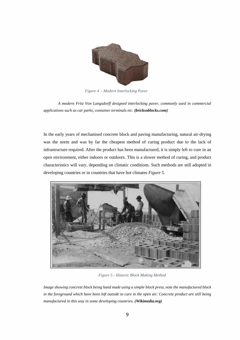
A modern Fritz Von Langsdorff designed interlocking paver, commonly used in commercial
applications such as car parks, container terminals etc. (bricksnblocks.com)
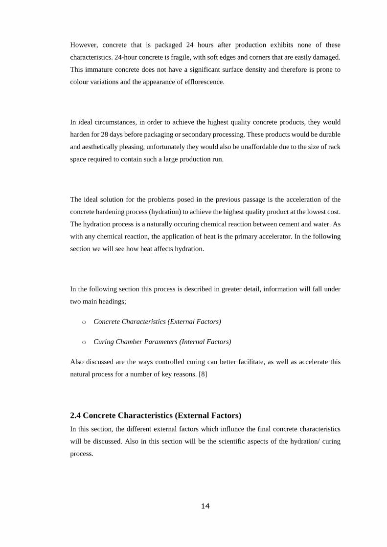
In the early years of mechanised concrete block and paving manufacturing, natural air-drying
was the norm and was by far the cheapest method of curing product due to the lack of
infrastructure required. After the product has been manufactured, it is simply left to cure in an
open environment, either indoors or outdoors. This is a slower method of curing, and product
characteristics will vary, depending on climatic conditions. Such methods are still adopted in
developing countries or in countries that have hot climates Figure 5.
Image showing concrete block being hand made using a simple block press, note the manufactured block
in the foreground which have been left outside to cure in the open air. Concrete product are still being
manufactured in this way in some developing countries. (Wikimedia.org)
Figure 4 - Modern Interlocking Paver
Figure 5 - Historic Block Making Method

10
Although open-air curing may be considered to be a relatively primitive method, it is still
common place in some modern production facilities, normally this method is employed for
engineering blocks rather than concrete paving products, as product aesthetics and uniformity
are not the main consideration. Figure 6 is a more modern representation of the air-drying
method. Concrete blocks are being manufactured by an ‘egg-laying’ block machine, so called
because of the way the machine ‘lays’ the product before moving to the next position to repeat
the process. The freshly made blocks are simply left outside to cure until they are sufficiently
hardened to the point that they can be banded, stacked, and stored in the yard. This process is
heavily dependent on weather as product cannot be made during prolonged spells of rain.
Image showing a modern air-dry application. Blocks are manufactured on a level concrete base and are
allowed to cure in the open air, when they are sufficiently hardened, they are banded with steel or plastic
bands before being stacked in a storage area prior to sale. Generally this method is only suitable for
engineering blocks where aesthetics and uniformity of colour is not the main concern. (HSA.ie)
2.2 Concrete Curing Nomenclature
Before discussing the hydration reaction, it is important to understand the terms: “cement”,
“concrete product”, “hardening”, “hydration” and “curing.” Each term has a specific meaning
and they are all too often used incorrectly.
o Cement – available in various blends as a powder, used as a binding material when
combined with water it forms a gel that, when hardened through a process called
Figure 6 - Modern Open-Air Curing

11
‘hydration’, binds course and fine aggregates (stone and sand) to form a strong, durable
and dense, rock-like structure, known as concrete.
o Concrete Product – for the sake of this thesis, manufactured from cement, water,
aggregates as well as pigments and admixtures in order to form products, when
hardened, for use in landscaping or hardscaping projects. These concrete products
include concrete block paving, concrete retaining wall block, slabs and curbstones.
o Hardening – a description of the process in which cement, water and aggregates are
combined, and given the correct environment and time become concrete. Critical to the
word hardening is the action of “to harden”, and not “to dry.”
o Hydration – Hydration is the description for the addition of water and is also the name
for the chemical process that occurs when cement and water are combined which results
in the hardening of concrete products.
o Controlled Curing – is a man-made process, with the aim of controlling the natural
hydration action of cement and water, through the correct and consistent application of
heat and moisture within a controlled curing duration. Controlled curing has a
beneficial influence on the cement hydration process and concrete properties including
economy, density, durability, strength and aesthetics are improved as a result. [8]
2.3 The Curing Process as Used in the Paving Industry
In the previous section we examined the different methods of air-drying, both the early and
modern scenarios featured required very little in the way of infrastructure or technology to aid
the curing process, such examples offer a very specific solution to a specific production
scenario. Now we will look at a more common model, in a paving production application, where
quality and output are the main driving force, curing technology is offered as a solution,
reducing cost/ m² or cost/ pallet of cured products. We will also examine the different types of
curing systems available today, and so will be our first introduction to the use of engineering
technology to improve the curing process, from the basic open rack systems to the more
technologically advanced single atmosphere type unit. The benefits and drawbacks for each
design will be discussed, and suggested improvements will also be considered.

12
It was already stated that we will consider curing systems to generally fall into three categories,
open rack air dry systems, semi-open chamber design, and finally, fully enclosed chambers,
and for the coming section we will adhere to these categories.
Before the different curing systems are outlined in the following pages, it will be useful to
discuss the implications that a properly specified and designed curing regime will have on a
company’s ability to produce consistent, qaulity product at a volume that is profitable.
The production of paving and landscaping products, including concrete block paving, concrete
retaining wall block, slabs and curbstones, includes several manufacturing steps.
These steps may be broken down into the following categories:
o Receiving, testing and storage of raw materials.
o Batching and mixing of raw materials.
o Pressing and/or vibration of raw materials into finished products.
o Hardening of finished products until packaging or optional secondary processing.
o Optional secondary processing, to produce value-added products. Processes may
include; grinding/ polishing, curling, splitting, bushhammering, shotblasting,
surface sealing etc.
o Packaging, storage and dispatch to customer-base.
With the current technology employed at the site, due to modern machinery offering impressive
cycle times, each one of these steps is typically carried out within a matter of minutes; from the
moment the raw ingredients are delivered to the plant, to the time that a freshly made sample
of paving emerges from the block machine may take as few as 15 minutes. Each step along the
process takes only seconds, minutes at maximum, except for the curing process, where the
hardening of the product occurs.

13
In a typical plant that doesn’t employ contolled curing practices, hardening the freshly formed
earth-moist concrete products requires anywhere from 24 hours in order to achieve packaging
strength, and up to 14 days to attain the strength necessary for secondary processing.
Hardening of concrete products normally occurs under ambient climatic conditions for 24 hours
on expensive wooden, plastic or steel production pallets in galvanized steel racks with a large
footprint, typically measuring over 900 m2 and up to 9 meters in height. The drawbacks of this
practice are evident;
o Rack capacity is larger than necessary to facilitate the slower turnaround time, i.e. 24
hours worth of production must be stored before dry product can be removed.
o Expensive production boards are tied up in the curing process, meaning greater
numbers of boards are required to maintain production levels. 5,000 boards or more
may be used in some paving and block plants.
After 24 hours, the concrete products have hardened sufficiently allowing for packaging.
Products which require secondary processing, a process becoming more common due to the
higher sales price, are packaged, stored in a stock yard for 2 weeks, brought back into the
factory, unpackaged, processed, repackaged and stored again in the stock yard from which they
are eventually shipped for final installation. This practice is both time consuming and wasteful;
o Product losses and product damage is likely due to the excessive handling.
o Packaging such as wooden pallets, plastic hoods/ sheeting, strapping etc. is wasted.
o Yard space is under-utilised in this ‘waiting phase’.
Concrete products typically reach their final strength after 28 days. At this time 99% of the
cement has been activated in the hydration process, acting as the glue that binds the raw
materials; stone, sand and other aggregates together. After the 28 day period, the concrete is
said to be mature; having reached its final strength. Edges and corners are durable and resist
breaking and chipping. Colours are fast and the surface is dense due to the complete reaction
of the cement.
14
However, concrete that is packaged 24 hours after production exhibits none of these
characteristics. 24-hour concrete is fragile, with soft edges and corners that are easily damaged.
This immature concrete does not have a significant surface density and therefore is prone to
colour variations and the appearance of efflorescence.
In ideal circumstances, in order to achieve the highest quality concrete products, they would
harden for 28 days before packaging or secondary processing. These products would be durable
and aesthetically pleasing, unfortunately they would also be unaffordable due to the size of rack
space required to contain such a large production run.
The ideal solution for the problems posed in the previous passage is the acceleration of the
concrete hardening process (hydration) to achieve the highest quality product at the lowest cost.
The hydration process is a naturally occuring chemical reaction between cement and water. As
with any chemical reaction, the application of heat is the primary accelerator. In the following
section we will see how heat affects hydration.
In the following section this process is described in greater detail, information will fall under
two main headings;
o Concrete Characteristics (External Factors)
o Curing Chamber Parameters (Internal Factors)
Also discussed are the ways controlled curing can better facilitate, as well as accelerate this
natural process for a number of key reasons. [8]
2.4 Concrete Characteristics (External Factors)
In this section, the different external factors which influnce the final concrete characteristics
will be discussed. Also in this section will be the scientific aspects of the hydration/ curing
process.

15
The Concrete Hardening Process
o Concrete is made up of 3 primary ingredients: aggregates (stone and sand), water and
cement, which are batched in the necessary proportions depending on the application.
o Aggregates are inert, i.e. they do not react and so have no influence over the reaction.
o Water and cement react at a temperature above 5°C to form a gel. This gel acts as glue
and binds the aggregates together, forming a tough, durable, rock-like substance,
known as concrete.
o In order for the combination of aggregates, water and cement to act as one – namely
concrete – the glue must be as strong or hard as the sand and stone. This strength gainis
known as the hydration process. The hydration process is further detailed in Figure 7.
Diagram illustrating the hydration process of cement, resulting in the formation of a gel, bonding the
fine and course aggregates to form a rock-like structure known as concrete. [8]
o The rate of strength gain of concrete is influenced by the chemical composition of the
cement, the fineness of its grinding and by temperature. Producers of concrete products
cannot influence either the chemical composition or the fineness that it is ground, but
they can influence the temperature and climate in which the concrete hardens. By
increasing the temperature of the concrete during the hardening period to between 35°C
and 40°C, the concrete will achieve 80% to 90% of its 28-day strength within 24 hours,
this truly being the key advantage of controlling the curing process. [8]
Figure 7 - Hydration Process
16
Concrete Early-Strength
It is in the interest of any producer wishing to achieve economic advantages with limited capital
investment to utilize controlled curing practices, the acceleration of the concrete strength gain
may be used not only for higher concrete quality, but also for same concrete quality with a
shorter hardening duration.
For instance, the acceleration of 24-hour concrete strength may be achieved within 9, 12, 14 or
18 hours depending on the size, shape and thickness of the concrete product. A 60 mm concrete
block paver will be capable of packaging after 9 hours of hardening, an 80 mm block paver
after 12 hours, a 100 mm block after 14 hours and a curbstone after 16 hours.
The acceleration of the strength gain of these products would allow a production facility with
storage space for only a single shift of production to double or, even, triple production capacity
by adding – for a relatively small investment - an accelerated hardening or curing system.
Another example of the economic benefit of achieving high early strength is the ability to
secondary process concrete products “in-line” immediately after the hardening process.
Instead of waiting 14 days for the concrete to harden sufficiently enough to undergo secondary
processing such as grinding and polishing, curling, shot-blasting, bush-hammering or splitting
requiring valuable stock yard space, creating additional packaging costs and causing damage
during internal transportation, hardening concrete products at elevated temperatures allows for
in-line secondary processing 16 to 24 hours after production. This practice has been
implemented with great success at the Hess 1 facility at the featured site, where it is possible to
convey hardened product directly back into the secondary processing plant via the use of
product transfer units and a slat conveyor system. This ‘auto-line’ system, as it is known,
provides a direct link between the curing chamber, to any one of the four secondary processing
lines, minimizing forklift movements, as well as removing the need for unnecessary handling
and packaging. [8]

17
2.5 Types of Cement and Binders
Having discussed the influence cement has on the curing process, we will now examine in
greater detail the different types of cementitious products used by the group at the production
site. Recipes employed at the site generally use four types of cement product to manufacture
concrete paving. The types are Rapid Hardening Portland Cement (RHPC), White Cement,
Lime Filler and Ground, Granulated, Blast-furnace Slag (GGBS). However, it is only RHPC
and GGBS usage that changed as a part of the chamber modernisation process and so it is only
these two types that will be discussed in detail. RHPC is the most common cement type used at
this site, making up the largest proportion of cement used at the site, at €86 per tonne, it
represents a major production cost. However cement alternatives are available on the Irish
marketplace. GGBS being one such alternative, at €65 per tonne, it is considerably cheaper. It
also requires far less energy to produce and hence has a smaller carbon footprint.
In scenarios where no controlled curing is carried out, i.e. open curing rack designs or older
semi-open designs, the practice of adding additional quantities of Rapid Hardening Portland
Cement (RHPC) is not uncommon, this an expensive practice with RHPC costing between €80
and €100 per tonne. This is typically done for two reasons.
o It is done to promote a higher rate of cement hydration within the product, allowing for
increased levels of product throughput with less than ideal curing set-ups. This was the
case with the older Hess 2 and Hess 3 chambers at the facility. Extra quantities of
cement were being added to produce the required early-strength, allowing product to
be removed from the chamber in a timely fashion. Producers should consider the fact
that curing with heat and moisture is less expensive than overdosing a concrete mix
with cement to achieve the same early strengths.
o Extra RHPC may be added to counteract reduced curing rates brought about by colder
weather and colder climates. Some producers will vary usage rates throughout the year,
increasing cement volumes with decreased temperatures, using the exothermically-
generated heat produced during the curing process to replace heat lost owing to the
colder curing conditions. [9]
Since the upgrade of the chambers, the sites Technical Department were able to reduce the
batched cement content in concrete recipes. This is in line with the system advantages of the
single atmosphere design as stated by its supplier. The controlled addition of heat and moisture

18
to the curing environment is allowing high early strengths to be achieved with a significant
reduction of cement content, due to the very effective heat retention properties offered by the
new chamber. Exothermically generated heat is now contained within the curing environment,
promoting a healthy and accelerated hydration process. If the heat retention properties of the
chamber are lacking, extra cement is typically used to account for the poorer curing climate to
achieve the same early-strength.
In the Hess 3 plant, prior to the chamber upgrade, a typical recipe for concrete used to
manufacture a standard 440 x 215 x 100mm engineering block will contain 300kg of RHPC,
approximately 4500kg of aggregate (dust, sand, stone etc.), water, and a small quantity of
chemical admixtures. Since the implementation of the controlled curing programme it was
possible to reduce the 300kg cement to 260kg, a reduction of just over 13%, resulting in
substantial savings which will be further discussed in the results section.
The Technical Department maintain a meticulous standard of documentation pertaining to
concrete recipes. Using these documents it will be possible to calculate any changes to the
concrete recipe structure and comparing them to recipes used prior to the chamber
modernisation. Actual cost savings, if any, will be calculated based on the recipes currently in
use at Hess 2 and Hess 3.
GGBS as a Cement Replacement
Ground Granulated Blast-Furnace Slag (GGBS) is a high performance alternative to traditional
cement that will increase the technical performance of concrete in most applications, improving
its appearance and minimizing its environmental impact, having a significantly smaller carbon
footprint when compared with RHPC. GGBS is a by-product from the manufacture of Iron that
is diverted from landfill, and up-cycled into a valuable product, it is used in combination with
Portland cement to produce superior, longer lasting concrete. A replacement rate of up to 70%
is generally used, depending on the application. On exiting the iron processing system, molten
blast furnace slag is rapidly quenched with water to form Granulated Blast-furnace Slag (GBS).
GGBS is produced by drying and grinding the GBS in a milling plant. [10]

19
Regarding the concrete recipes used by the group, the addition of the Hess 2 and Hess 3 single
atmosphere chambers made it possible to use GGBS in concrete mixes. Prior to the upgrade, it
was not economically viable to use GGBS because although the temperature and moisture
conditions during curing have similar effects on the setting properties, strength, and
development of both concrete containing GGBS, and that made with only Portland cement,
curing times would have needed to be significantly longer since they typically develop strength
more slowly. [11]. Using GGBS concretes in the older chambers at the site would have greatly
slowed down product throughput levels, given the slower hydration rate.
By using a single atmosphere curing chamber, the ability to accurately control the addition of
heat and moisture to the curing environment meant it was now possible to begin manufacturing
concrete products containing a proportion of GGBS, resulting in a sizeable cost saving. The
price per tonne of GGBS is approximately €65 compared with €90 per tonne for RHPC. In the
results section, an actual cost saving will be calculated for an average production day at the
Hess 3 plant.
Despite the reduction of RHPC content, and the addition of slower-hydrating GGBS, it is still
possible to achieve extremely high product early-strength, using reduced curing times, thanks
to the controlled curing programme. The effectiveness of the system is such that strengths
typically exceed minimum requirement by a considerable margin, even with cement usage
reductions by as much as 10%.
Environmental Benefits of Using GGBS
After water, concrete is the most consumed substance on earth, with 2.5 tonnes of concrete
poured for every person on the planet every year. The active ingredient for concrete is cement,
whose production is responsible for 5% of global CO2 emissions. This is due to the way cement
is manufactured (very high energy demands and the high carbon content of the raw material;
limestone). For every tonne of cement produced, a tonne of CO2 is released into the atmosphere,
an alarming figure for a widely used construction material. As already mentioned, Ground
Granulated Blast-furnace Slag (GGBS) is an environmentally friendly cement substitute,
manufactured from a by-product of the iron-making industry. Using one tonne of GGBS in

20
concrete reduces the embodied CO2 by around 900kg, compared to using one tonne of Portland
cement, and also increases its durability. [12]
The groups chosen GGBS supplier, utilises the best available technology to manufacture a
cement with a carbon footprint 16 times lower than other cements produced in Ireland. [10]
Figure 8 - Image Showing GGBS (Left) and RHPC (Right).
(Ecocem.ie)
21
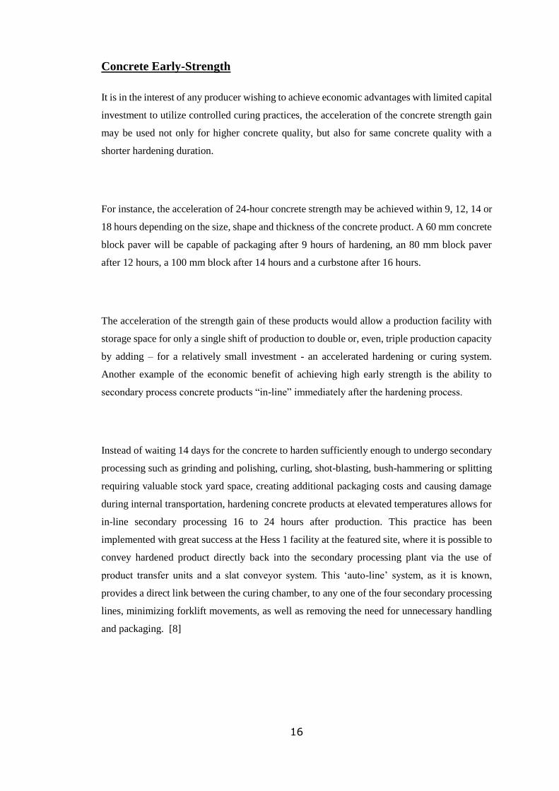
Figure 9 - Graph Showing CO2 Emissions from Portland Cement Compared with GGBS.
(Passivehouseplus.ie)
CO2 and Other Pollutants Associated With Cement Manufacture
In Ireland, cement manufacture is currently the second largest industrial source of CO2 and
NOX emissions, after the generation of electrical power from fossil fuels. Almost one tonne of
CO2 is generated in the manufacture of one tonne of Portland cement, along with 2kg of SO2,
3.5kg of NOX and 2kg of CO.
On the other hand GGBS cement is manufactured from an industrial by-product, and has a
minimal CO2 footprint, and zero harmful pollutant emissions such as SO2, CO and NOX. Figure
9 illustrates the difference in CO2 emissions between GGBS and Portland cement, and
demonstrates the Carbon savings that can be made by using GGBS cement.

22
2.6 Chemical Aids to Concrete Curing (Admixtures)
There are numerous chemical additives available on the market for use in the concrete industry.
Generally referred to as ‘Admixtures’, there are a number specifically designed for the
manufacture of concrete pavers, which are generally added to improve quality, reduce defects
and to improve cycle times.
Typically dosage rates for these chemicals are calculated from either cement or water volume
used in the concrete mix. The chemicals are introduced directly into the mixing cycle through
an accurate dosing pump. In this section we will discuss the use of two such admixtures, both
of which are used by the group for the manufacture of concrete paving at the site. The two main
admixtures currently in use are:
Water Reducers (Plasticizers)
o A surfactant used to reduce surface tension between ingredients during the concrete
mixing cycle, allowing for a more homogenous concrete mix, resulting in better surface
finish as well as better workability using reduced water content. The lower water
content produces a stronger concrete mix.
o Reduces air entrainment in the concrete mix, reducing the creation of pores and hence
reducing capillary action within the concrete.
Pore Blocking Water Proofer
o Blocks any pores which may form inside the concrete, reducing water permeability and
movement of water through capillary action.
o Reduces occurrences of primary and secondary efflorescence.
Water Reducers (Plasticizers)
Impermeable water reducing concrete plasticizers are typically made from modified Lignin
Sulphonate, a by-product from the wood pulping industry. This admixture is extremely oily in
texture, similar to mineral oil, with a light brown colour.
The specific plasticizer used by on site, MasterLife WP701, acts as a surfactant, i.e. it reduces
surface tension between the concrete-mixture components. This concrete admixture also limits

23
the air entrainment factor of concrete, which reduces concrete’s permeability against capillary
water absorption and reduce the volume of required concrete mixing water.
Fields of Application:
o Used in all kinds of concretes that will be temporarily or permanently exposed to water.
Advantages:
o Reduces permeability against capillary water absorption compared to concrete without
admixture.
o Improves mixture properties by reducing water / cement ratio without decreasing
workability, i.e. provides excellent workability with lower water usage, less water
makes for stronger concrete.
o Reduces mixture segregation and bleeding, a more homogenous mixture is formed.
o Makes it easier to obtain surface finish.
o With regards to concrete paving manufacture, it may help reduce block machine cycle
times, as the admixture acts as a compaction aid, resulting in a better surface finish in
a shorter time.
How it Works
Admixtures generally go into reaction only with the cement or binding agent. When the
admixture is added to the concrete, it is absorbed by the particles of the binder (cement). The
particles of the binder push each other by electrostatic force. Thus the desired workability is
obtained even though the volume of batched water within the mix is significantly reduced.
Proportional with the decrease of mixture’s batched water volume, mechanical strength will
increases.
Application Procedure and Dosage:
Binder (cement, GGBS etc.) and aggregate must be mixed until a homogenous mixture is
obtained. After 50%- 70% of the batched water has been added to the mixture, MasterLife
WP701 is then added, followed by the remaining quantity of batched water. The concrete must
then be mixed for 60 sec. or for a duration determined in laboratory experiments.
MasterLife WP 701 is suggested to be used at a rate of 0.5-0.8 kg for 100 kg of binder. [13]

24
Pore Blocking Water Proofer
CHRYSO Fuge C is a pore blocking water proofer which reacts with the lime in the cement to
form water repellent particles. These obstruct the capillary action within concrete. It also
enables the concrete and mortars to resist the penetration of water through the capillary action
or through water under pressure.
Fields of Application:
o Concrete where excellent efflorescence control, superior water repellence and low
absorption are desirable.
o Specially recommended for pavers and architectural blocks where efflorescence
prevention is required.
Advantages:
o Provides superior primary and secondary efflorescence control.
o Reduces concrete water permeability and absorption.
o Reduces mix stickiness and avoids shoes, molds and build up in hoppers etc.
o Improves concrete chemical resistance and durability.
Application Procedure and Dosage:
CHRYSO Fuge C is miscible in water. It must be added preferably to the mixing water. The
dosage of CHRYSO Fuge C also depends on the Water/Cement ratio of the concrete.
Dosage range: 0.3 to 1.5% of binder content. [14]
2.7 Curing Chamber Parameters (Internal Factors)
This section is concered with the different aspects of the curing environment which can be
modified through the use of curing chamber technology such as temperature control, humidity
control, air velocity reduction etc.

25
Heat and Moisture
In simple terms, controlled curing is about providing the ideal atmosphere for the hydration process
to take place. Hydration is a natural process, although by providing an atmosphere that contains a
fine balance of temperature and humidity it ensures that environmental factors within the curing
chamber are not having any negative impact on this process.
Care must be taken regarding the relative humidity when attempting to harden product at elevated
temperatures. As air temperature is increased from ambient temperature, say 20°C, to 40°C, the
air’s capacity to absorb moisture increases as the relative humidity decreases. In this case, the air
within the curing chamber will act as a sponge, absorbing moisture from all surfaces exposed to
the air, including the freshly made concrete.
Freshly formed concrete products contain a large quantity of moisture (water). Until this water has
been utilized in the hydration process, to form a gel, it is critical to maintain a relative humidity
within the curing environment to 95% or over, in order to prevent the moisture from evaporating
from the surface of the fresh concrete product. If moisture is evaporated form the surface of the
concrete too early, the concrete surface density will decrease causing poor abrasion resistance.
Capillaries may also form within the concrete, allowing water penetration and the transportation
of calcium hydroxide to the surface, resulting in the appearance of efflorescence. Water loss in
fresh concrete causes brittle corners and edges which are prone to breakage. Conversely, too much
humidity during hardening can also have a negative impact as excess moisture in the presence of
cement containing high levels of free-lime will cause the appearance of primary efflorescence
which occurs during the hardening process.
Humidity and Relative Humidity Explained
Humidity and relative humidity, being some of the more important factors of the controlled
curing process are explained in the following section. Also explained is how they influence the
curing process. It should be remembered that the word “relative” is very important in the
understanding of relative humidity as the humidity level is always relative to the temperature.

26
For example:
o 1 m3 of 20°C air containing 16 grams of water has a relative humidity equal to 93%.
o 1 m3 of 40°C air containing 16 grams of water has a relative humidity equal to 31%.
If the concrete curing temperature is increased from 20°C to 40°C without the addition of moisture,
a poor curing environment will result, causing reduced strength and brittleness. The reason for this
is that the air acts as a sponge, trying to attain its natural (saturated) state, i.e. rH equal to 100%.
The 40°C air will attempt to reach this saturated state and will cause moisture to evaporate from
the concrete surface in a process called ‘wicking’, until it has reached 100%.
For example:
o 20°C air is saturated at 17 grams of water per m3.
o 40°C air is saturated at 51 grams of water per m3.
A typical concrete curing chamber area is equal to 25 m wide x 25 m deep x 8 m high, in other
words containing a 5,000 m3 volume of air. The difference in the amount of water required to bring
5,000 m3 of air to a saturated state at 40°C and the amount required when the air is at 20°C is 170
litres (5,000*[0.051- 0.017]). If this 170 litres of water is not added to the curing environment, by
a fogging system or by other means, the moisture differential will be reduced by the air evaporating
water from the concrete to achieve saturation. Figure 10 illustrates how the relative humidity
values will change with increasing temperatures, and highlights the importance of adding water to
the curing environment to ensure a value close to the saturation point is maintained.
Thus the control of moisture is as critical to the quality of the concrete product as the control of
temperature. Without enough moisture the concrete will be less dense and easily damaged. Too
much moisture in hardening area will cause staining from drops of water and the appearance of
primary efflorescence. [8]

27
Pictorial representation of the how increasing temperatures can influence the relative-humidity. At the
10°C state, the air is saturated, i.e. it is at 100% rH, by increasing the temperature of the air, we increase
the volume of water that can be ‘carried’ by the air and so the rH value will drop. [8]
Air Velocity
The importance of air velocity in the hardening area is based on 3 parameters:
o The speed or velocity of the air.
o The air temperature.
o Relative humidity of the air.
The influence of air velocity on the concrete hardening process
Air velocity affects the concrete surface by changing the amount of water that is either deposited
through condensation, or removed by evaporation. Depending on the speed of the air, the levels
of condensation and evaporation can increase by up to a factor of 10.
The most common issue related to air velocity in the hardening of concrete products is trapped
air (zero air speed) or extremely high air speed. Trapped air is usually caused when the storage
area is lined with insulation panels – especially the ceiling on top of the storage area. The
insulated ceiling has trapped the air causing it to stop. This can result in heat build-up and
inconsistent temperature or humidity compared to other zones of the hardening area, and thus
lead to colour differences, poor product density and a probability of the appearance of
secondary efflorescence.
Figure 10 - Diagram Illustrating Relative Humidity
28
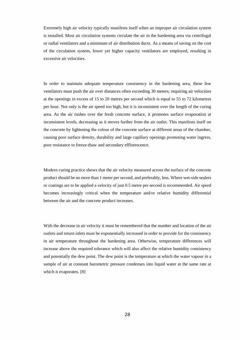
Extremely high air velocity typically manifests itself when an improper air circulation system
is installed. Most air circulation systems circulate the air in the hardening area via centrifugal
or radial ventilators and a minimum of air distribution ducts. As a means of saving on the cost
of the circulation system, fewer yet higher capacity ventilators are employed, resulting in
excessive air velocities.
In order to maintain adequate temperature consistency in the hardening area, these few
ventilators must push the air over distances often exceeding 30 meters; requiring air velocities
at the openings in excess of 15 to 20 metres per second which is equal to 55 to 72 kilometres
per hour. Not only is the air speed too high, but it is inconsistent over the length of the curing
area. As the air rushes over the fresh concrete surface, it promotes surface evaporation at
inconsistent levels, decreasing as it moves further from the air outlet. This manifests itself on
the concrete by lightening the colour of the concrete surface at different areas of the chamber,
causing poor surface density, durability and large capillary openings promoting water ingress,
poor resistance to freeze-thaw and secondary efflorescence.
Modern curing practice shows that the air velocity measured across the surface of the concrete
product should be no more than 1 meter per second, and preferably, less. Where wet-side sealers
or coatings are to be applied a velocity of just 0.5 metre per second is recommended. Air speed
becomes increasingly critical when the temperature and/or relative humidity differential
between the air and the concrete product increases.
With the decrease in air velocity it must be remembered that the number and location of the air
outlets and return inlets must be exponentially increased in order to provide for the consistency
in air temperature throughout the hardening area. Otherwise, temperature differences will
increase above the required tolerance which will also affect the relative humidity consistency
and potentially the dew point. The dew point is the temperature at which the water vapour in a
sample of air at constant barometric pressure condenses into liquid water at the same rate at
which it evaporates. [8]

29
2.8 Types of Curing Chamber Currently in Use
In this section we will discuss the three main types of curing chamber currently used in the
manufacture of engineering blocks and paving products, namely Open, Semi-Open and Fully
Enclosed Single Atmosphere Chambers.
Open Rack System
Until quite recently, the majority of curing racks were designed and built without any type of
housing or air recirculation system. For the most part, this has changed; in-process quality
control is becoming increasingly important amid fierce competition and cost pressure. Despite
the benefits of controlled curing and increased industry competiveness, some fully open-rack
units are still being built today, Figure 11. [6]
Advantages of open-rack/ air-dry systems:
o Lower installation costs, when compared to semi-open, and fully enclosed types.
o Time for erection and installation is kept to a minimum.
o Ongoing maintenance costs are significantly reduced, i.e. no rack doors, no burner/
ventilation equipment, no insulation etc.
o No ongoing fuel costs.
o Visibility of operations inside the chamber area is typically very good, i.e. the use of
closed-circuit television (CCTV) cameras is generally not required.
Disadvantages of open-rack/ air-dry systems:
o Increased likelihood of concrete efflorescence.
o Increased likelihood of colour variations to exist between production runs.
o Product will be less dense, rates of capillary action will be increased leading to other
quality issues.

30
o Risk of the occurrence of condensation within the plant environs under certain
conditions.
o Due to the poorer rate of cement hydration, extra quantities of cement may have to be
used, leading to increased volumes of concrete admixtures/ pigments, whose dosage
rates are typically calculated proportional to the cement volume, thus increasing batch
cost.
o Early-strength results will be poorer if the climate is not controlled, leading to slower
product turnaround times.
o Due to the longer curing times, larger or more racks may be required in order to meet
required output levels.
Image showing a modern air-dry application. Although the curing chamber is located inside the
main production hall, the racks are of an entirely open design, i.e. no inter-rack insulation exists. Note
the extractor fans located near the top of the image, these help remove humidity from the factory
environment, minimising the risk of condensation.
(modern4concrete.com)
Figure 11 - Modern Open Rack Design

31
Semi-Open Curing Chamber Systems
The semi-open curing chamber design is one of the more common designs adopted by plants
that manufacture concrete paving products. The entire curing chamber generally consists of a
number of individual curing chambers placed side-by-side, see Figure 12, with individual
openings covered by an insulated roller-shutter door, usually at the front of the chamber for
last-in-first-out (LIFO) storage. The division between each individual chamber, as well as the
ceiling space is generally covered with an insulating material, see Figure 12.
Figure 12 - Two Images Illustrating the Semi-Open Curing Chamber Design

32
Two images depicting the semi-open curing chamber design. Note that each chamber is covered by an
insulated roller-shutter door. Freshly made product will be placed into one of the racks, and cured
product will be removed from the other rack, this cyclical process ensures a continuous supply of
production boards back to the block machine, allowing it to continue operating.
(esbro.pl), (Bft-international).
During a typical production day, two of rack doors will be open. Newly cast wet product is
placed into one selected rack, the ‘wet rack’, whilst dry product is being removed from another,
the ‘dry rack’. At the beginning of a production shift, an empty chamber is selected and since
the door is open, the chamber climate is at ambient temperature and humidity.
As the wet rack is filled with fresh product, the climate in this rack changes slightly due to the
heat and humidity produced by the fresh concrete products. When the chamber is completely
filled, the roller-shutter door is closed, and the pre-set automated curing regime will begin. The
curing regime has 4 distinct phases; pre-set, ramp, dwell and cool-down, during which times
the chamber temperature is increased, maintained at a raised level and then reduced- Figure 13.
Another previously emptied chamber will then be put into use as the new wet rack.
Graph showing the different stages of the curing regime, as applied to the individual curing chamber
design. (CDS-group.co.uk)
At the time of purchase, this design most likely offered the customer a good compromise
between installation time and costs, operating costs and the level of atmospheric control. The
Figure 13 - Graph Showing Curing Regime

33
group featured in the thesis selected this chamber design for the Hess 3 plant in 1994 and the
Hess 2 plant in 1996. The chambers were designed and built by an British group, who continue
to offer similar solutions, albeit updated models, to this day. We will now examine some of the
advantages and disadvantages of this design, while referring to the group’s experience of the
system as much as possible.
Advantages of the semi-open curing chamber design:
o Generally consists of a free-standing structure which can easily be integrated into the
main production hall.
o Finger Car, elevator, and lowerator have minimised exposure to the hot and humid
conditions generated inside the chamber.
o Individual control of conditions inside the rack pairs is possible.
o Due to the open nature, operator visibility is generally good, lessening the need for
CCTV cameras.
o More exothermically generated heat is retained when compared with fully open
designs. Moisture is also retained to a degree.
o Good level of throughput is possible with correct burner sizing and adequate levels of
insulation.
Dis-advantages of the semi-open curing chamber design:
o Higher energy costs when compared with single atmosphere fully enclosed units, heat
generated by curing concrete is allowed to escape to atmosphere. Only when the racks
doors are closed is when the true controlled curing process can begin, depending on the
production rate, it may take 2-3 hours to fill a rack pair before the doors will be closed.
By this time, heat generated by the hydration process has already been lost to
atmosphere.
o In older or less sophisticated systems, because of the open nature of the wet rack, the
first product entering the rack will be cooler than the product placed at a later stage,
this is because the wet product will begin to cure, releasing heat from the hydration

34
process, resulting in greater heat levels as the rack begins to fill with curing concrete.
This temperature differential will inevitably lead to quality issues.
o Rack doors are prone to damage, which is often inflicted by misplaced or crooked
production boards on the finger car, damaging the door as it drives through the
threshold to place product into the racks.
o Adequate safety measures must be in place to insure the finger car will not
enter the rack if the door is in closed position.
o Lasers or optical sensors may be installed to insure that there is nothing
obstructing the door opening before the rack doors begin to close.
o Condensation is likely to occur inside the factory environment.
In the following section one of the most efficient and production oriented curing chamber designs on
the market today will be examined in detail. This chamber design boast numerous benefits over other
designs as we will now discuss in more detail. Below is a simple definition of a single atmosphere
curing chamber, stated by the supplier.
Fully Enclosed Single Atmosphere Chamber
The focus of this thesis is the upgrade of the Hess 2 and Hess 3 curing chambers at the featured
production plant, to the standards offered by a modern single atmosphere curing chamber, such as
the 2008 commissioned model already in use at this site. The model chosen for the upgrade, as
mentioned earlier, is an ultra-modern, German designed and built, single atmosphere curing
chamber. In this section we will discuss some of the design features and specifications which make
this design one of the most efficient chambers currently on the market.
“Single Atmosphere Curing Chamber is a single room in which the temperature and humidity remain
constant 24 hours per day and 7 days per week. The concrete product enters the chamber through a
small opening immediately after production and leaves the chamber through a small opening and is
immediately secondary processed and/or packaged.” Figure 14. - Kraft Curing Systems GmbH. [8]

35
(Kraft Curing Systems GmbH)
o The single atmosphere concrete curing system provides controllable curing
temperatures between 35°C and 40°C and relative humidity between 73% and 98%,
eliminating issues due to excessive condensation. Temperature and humidity are
consistent throughout the system.
o The Air Circulation System operates constantly and provides for even temperature and
humidity throughout the single atmosphere curing chamber - top to bottom and front to
back. The air heating and circulation unit (AHU) is manufactured with an aluminium
frame and stainless steel insulated body with heat exchanger, burner and chimney. The
equipment installed in both chamber are similar in design, the only difference being
scale and output. For example, the AHU boasts a heat output of 500kW/h in the Hess
3 chamber with a smaller 300kW/h unit employed in the Hess 2 curing chambers. Both
units offer air-handling rates of 35,000 m3/h and 23,000 m3/h respectively.
o A Heat and Moisture addition system includes a fog system, utilizing multiple micro-
nozzles and pressurized water, provides a truly atomized moisture source when the
relative humidity falls below the set-point. The system includes a water filtration
system, 150 bar pump, hoses and 4 litre per hour micro sized spray nozzles. A high
quality Weishaupt burner, stainless steel heat exchanger and combustion chamber
provide heat as required for the acceleration of the concrete curing process.
Figure 14 - Single Atmosphere Chamber
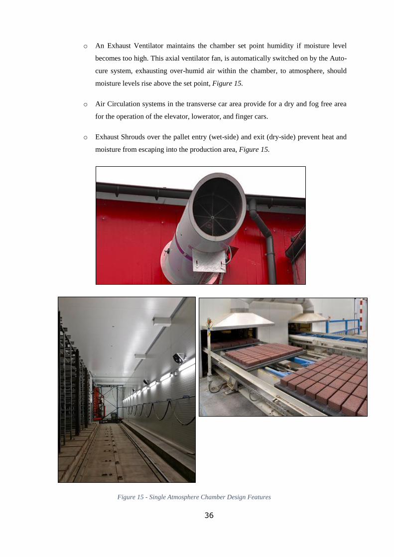
36
o An Exhaust Ventilator maintains the chamber set point humidity if moisture level
becomes too high. This axial ventilator fan, is automatically switched on by the Auto-
cure system, exhausting over-humid air within the chamber, to atmosphere, should
moisture levels rise above the set point, Figure 15.
o Air Circulation systems in the transverse car area provide for a dry and fog free area
for the operation of the elevator, lowerator, and finger cars.
o Exhaust Shrouds over the pallet entry (wet-side) and exit (dry-side) prevent heat and
moisture from escaping into the production area, Figure 15.
Figure 15 - Single Atmosphere Chamber Design Features

37
(Kraft Curing Systems GmbH), (pavingexpert.com)
Advantages of the single atmosphere curing chamber:
o Consistency- each and every concrete product entering the single atmosphere curing chamber
enters the chamber within 1 minute of being produced. The single atmosphere chamber
remains at the same temperature and relative humidity 24 hours per day, 7 days per week,
regardless of the season. As long as the temperature and relative humidity in the curing area
are consistent, concrete products will always be hardened in the same environment with the
same results. [8]
o Capital Cost- the single atmosphere curing chamber provides significant savings over the
individual curing chamber design. The cost of internal walls, motorized roller-shutter doors,
independent temperature controls, control dampers or valves, exhaust systems and larger
capacity heating equipment required for the individual curing chamber design contrasts
sharply with 20% additional chamber wall and ceiling insulation and additional air circulation
equipment. This adds up to a price difference equal to over €150,000.00 in favor of the lower
priced single atmosphere curing chamber. [8]
o Operating costs- since the single atmosphere curing chamber remains at the same temperature
and humidity throughout the production calendar, unlike the individual curing chamber, there
is no heating or cooling effect within the curing area. The energy cost of curing 1 m2 of
concrete block paving in the single atmosphere curing chamber is 1/3 the cost of the individual
curing chamber. Due to the lack of moving parts (door motors, valve/damper actuators) and
lower and consistent operating temperatures, maintenance costs savings are on the order of
80% versus the individual curing chambers. [8]
o Quality- A typical concrete block paving production machine will produce approximately 25
to 75 tonnes of fresh ambient temperature concrete per hour. Thus the heating system is
required to produce only enough heat per hour to raise the temperature of this amount of
(Top) Image showing the exhaust ventilator, used to remove moist air from the chambers
should the humidity level rise above the desired set point.
(Bottom Left) View of the finger car traverse area. Located in part of the chamber known as
the vestibule. The arrangement of the ventilation ducts, and the addition of wall mounted fans in this
area serve to reduce the levels of humidity and confine it to the rack space. This helps to minimise
exposure of the finger to excessive humidity as it moves between rack positions.
(Bottom Right) Shrouds located over the dry-side conveyors at the original single atmosphere
chamber at the Hess 1 plant. The shrouds recover any heat that escapes through the chamber exit point,
this hot air is channelled back into the top of the chamber, minimising energy losses.

38
concrete from ambient to the maximum required curing temperature – approximately 35°C to
40°C. This means a smaller heater, smaller burner and lower incoming air temperature –
reducing the chance of evaporating moisture from the fresh concrete. [8]
o Mix-Design Optimization- Many producers of concrete products use additional cement
content during colder production months in order to compensate for lower ambient
temperatures; the additional cement creates more exothermic energy and provides for a
warmer curing area. The use of a single atmosphere chamber makes this practice no longer
necessary and the consistency in the curing area allows the concrete producer to reduce
cement content, thus reducing production costs. [8]
Disadvantages of the single atmosphere curing chambers:
In terms of product quality and operational efficiency, it is clear that the advantages of single
atmosphere systems are many. However from the perspective of an end-user or maintainer, there
exists a small number of disadvantages which should be highlighted.
o Adverse operating conditions for machinery within the curing chamber- The finger car,
elevator, lowerator and all related hydraulic and electrical gear associated with this
equipment is now located within the environs of the chamber.
Special care must be taken to ensure that the IP ratings of all equipment
inside the chamber area are compatible with the environment. This ‘up-
rating’ of equipment will lead to an additional expense.
Coolers may need to be installed on some electrical panels to ensure that
the equipment inside is not pushed beyond their normal operating
temperatures.
Corrosion will occur on all uncoated surfaces. All surfaces should be
either painted or galvanized, in the case of moving parts (chains and
sprockets etc.) they should be greased or oiled.
o Poor Visibility- A network of CCTV cameras may need to be installed to allow
operators to maintain a watchful eye on all operations within the curing chamber.

39
Case Study- Superbet, Poland
Having discussed the pros and cons of the single atmosphere curing model, the following case
study will help further describe the merits of the system, from the viewpoint of a practical
application. The setting for this case study is a large manufacturer of concrete paving products
in Łosice, Poland. The production facility at the Polish plant is comparable to that of the plant
featured in this thesis, and because of this, the cost, quality, and production problems in both
cases are therefore similar. Increasing pressure from their respective competitors, and
increasing energy costs meant that both companies turned to a well-known German
manufacturer for a solution. The ideal solution in both cases was found to be a single
atmosphere curing chamber, the benefits of which have become clear to both companies.
Case Study- Superbet, Poland.
Started in 1983, “Superbet is a small to mid-sized company operating with highly efficient
production equipment. The company focuses on continual improvement and innovation.”
The owner of the Superbet Company, Josef Zawadski claims that often during the production
of these high quality paving products, -“complaints regarding efflorescence and inconsistent
colours are received, although according to DIN and EN-BS 1338:2005, (quality standard for
precast concrete paving blocks) these are not defects. Customers do not accept this logic. They
expect that - along with technical and functional characteristics such as strength, resistance to
freeze-thaw and durability – they are also guaranteed colour quality and consistency. Thus, it
is important for Superbet to find solutions for problems including efflorescence and inconsistent
colours. The solution came quite unexpectedly.”
For the Superbet Company, the solution was found, and in mid-2015 the company purchased a
single atmosphere, accelerated curing system. The installation duration for the curing system
was a total of 11 days. Upon installation completion, equipment commissioning, customer
training and system balancing and climate data logging required an additional 5 days. During
this time, the chamber is slowly heated to the desired curing temperature and relative humidity
– usually between 35 °C and 40°C and between 85% and 95% rH, Figure 16. Since the
installation of the new curing system, Superbet has seen the following results:
o Completely consistent colours
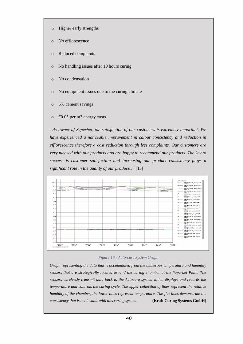
40
o Higher early strengths
o No efflorescence
o Reduced complaints
o No handling issues after 10 hours curing
o No condensation
o No equipment issues due to the curing climate
o 5% cement savings
o €0.03 per m2 energy costs
“As owner of Superbet, the satisfaction of our customers is extremely important. We
have experienced a noticeable improvement in colour consistency and reduction in
efflorescence therefore a cost reduction through less complaints. Our customers are
very pleased with our products and are happy to recommend our products. The key to
success is customer satisfaction and increasing our product consistency plays a
significant role in the quality of our products.” [15]
Graph representing the data that is accumulated from the numerous temperature and humidity
sensors that are strategically located around the curing chamber at the Superbet Plant. The
sensors wirelessly transmit data back to the Autocure system which displays and records the
temperature and controls the curing cycle. The upper collection of lines represent the relative
humidity of the chamber, the lower lines represent temperature. The flat lines demonstrate the
consistency that is achievable with this curing system. (Kraft Curing Systems GmbH)
Figure 16 - Auto-cure System Graph

41
3 Methodology
Discussed in the following section are the factors that led to the group investing almost
€500,000 in the installation of two, state-of-the-art controlled curing systems, replacing two
ageing and inefficient units. Also discussed are the ways and methods by which the merits of
the system will be verified through the analysis of records and documentation. The following
list is a recap of the factors which led to the modernisation, they will be discussed in greater
detail in the following pages.
Main Factors which lead to the decision to upgrade the curing chambers at the Hess 2 and Hess
3 Plants:
o Excessive fuel/ energy usage- The semi-open curing chamber design as well as poor
overall condition of insulation lead to excessive heat loss, and therefore increased
dependency on artificially generated heat. The original Hess 1 single atmosphere
chamber, commissioned in 2008, served as a benchmark as will be discussed in the
following section.
o Production- Slower curing times in the existing chambers were causing production
bottlenecks, this issue was particularly prevalent in the smaller Hess 2 chambers, where
24 hour production capabilities were diminished because of this fact.
o Recipes- Because of the increased hydration rate brought on by accelerated curing,
made possible through the use of the newly installed single atmosphere chamber, it was
possible to modify the concrete recipe, reducing overall cement usage and hence
reducing cost.
o Quality- The installation of the new single atmosphere chamber at Hess 2 and Hess 3
lead to an instant improvement in overall product quality- a harder, denser, colour
consistent product resulted, with virtually no incidents of concrete efflorescence.
In order to quantify these factors the following methodology has been employed, allowing data
to be processed and represented graphically or otherwise. As part of the methodology it was
necessary to introduce a new unit of measurement to maintain the validity of certain methods
of comparison.

42
Introduction of a New Unit of Measurement:
As mentioned in the Dissertation Scope and Limitations section of the thesis, it was
necessary to introduce a new unit of measurement to quantify some important factors. The
new unit is a ‘pallet’, and will be used when calculating ‘curing cost per pallet’ for example.
This unit is ideally suited to this thesis as it transcends product type and size and is common
to all three curing chambers featured. One ‘pallet’ or production board, contains the product
that is manufactured during one block machine cycle, which roughly corresponds to 1m²
of product. Pallets containing freshly made product are placed inside the chambers to allow
the curing process to commence. This new unit of measurement holds validity for the
following reasons;
o Products manufactured at Hess 1, 2 and 3 differ. For example Hess 1 mostly
manufactures concrete paving slabs, stones and other landscaping products, and
Hess 3 mostly manufacturers engineering blocks. For this reason, most of the
emphasis will be placed on comparing operating costs of each plant at different
stages of its own life and not comparing costs between one plant and another, in
this way we are comparing ‘like with like’ and so it will not be necessary to analyse
the exact contents of the curing chamber.
o Curing costs per pallet will depend heavily on the level of product throughput and
the operating hours, i.e. 18-hour, two-shift cycles, and 12-hour days etc. Because
of this, merit will be placed on average costings and not actual costings due to the
highly variable nature of curing cost per pallet. Calculating costs based on actual
volumes using the available information would quickly become unmanageable and
does not necessarily offer any advantage.
The ‘pallet’ unit of measurement will feature heavily in the coming chapter, particularly
with reference to the Fuel & Energy Usage as well as the Production sections. This unit is
an example of the unique methodology that must be applied to this project to help quantify
and analyse key factors.

43
3.1 Fuel/Energy Usage
Prior to the upgrade of the two curing chambers, Hess 2 and Hess 3, the main cost and the main
decision making factor associated with the current design, was fuel consumption. Figure 17.
The original, semi-open curing chamber design had, at that stage, been operating for over 20
years, and was beginning to show its age. Insulation used in the construction of the original
chambers was sub-par, in comparison to more modern and efficient insulation types. The
insulation had also become damaged in some areas, particularly in the dividing walls between
each rack, this meant that heat was free to migrate through the rack system and escape through
open roller-shutter doors belonging to racks that are currently being filled/emptied during
production. Due to this loss of heat, extra heat needed to be created to replace this loss, and
maintain the operating temperature at the necessary set-point.
Graph showing the cost comparison between the modern Hess 1 chamber (2007) and that of Hess 3
(1994). The data was collected over a number of days in June 2014, prior to the modernisation of Hess
3. The orange bar represents the Hess 3 fuel cost, the blue bar represents the Hess 1 fuel cost. This graph
is one of the key pieces of data which lead to the decision to upgrade the curing chambers at Hess 2 and
Hess 3.
(Company Report)
From Figure 17, it can be seen that there is a stark contrast between the fuel costings for each
the two plants. Switching to a gas-fired model at the Hess 3 plant would have amounted to a
small saving, but would remain highly uneconomical to operate without the necessary upgrades
to the insulation. In order to compare the chambers and the fuel usage, conversions of the gas
and diesel fuels to the common unit of Kilowatt-hour (kWh) must be undertaken. The correct
conversions can be found online on the SEAI (Sustainable Energy Authority of Ireland)
Hess 3
Hess 1
Figure 17 - Hess 1 vs. Hess 3- Fuel Cost
Fuel C
ost (€
)

44
website. The table describes the projected savings that could be achieved by upgrading the Hess
3 chamber in line with the more modern Hess 1 chamber which was installed in 2007 and
operating since 2008. If this data is taken as a typical week with the average level of production
in each factory for this given week, there would be savings of €2,500. This would equate to
yearly savings of around €125,000. [16]
Table 1 - Hess 1 vs. Hess 3, kWh Requirement
Weekly projected savings if Hess 3 were to switch to gas fuelling and have a modern enclosed, single
atmosphere system comparable to Hess 1. If this data is taken as a typical week with the average level
of production in each factory for this given week, there would be savings of €2,500. This would equate
to yearly savings of around €125,000.
(Company Report)
By referring to gas meter readings, it was possible to calculate the current running costs of the
upgraded chambers and compare with that of the old system. Due to the different fuel types,
i.e. Diesel in Hess 3, and Liquefied Petroleum Gas (LPG) in the Hess 1 single atmosphere
chamber, it is necessary to convert them to a common mode of comparison which will be energy
requirement, in Kilowatts.
3.2 Effect on Production
Although this theme may be considered secondary to the issue of excessive operating cost,
product throughput is still a major factor, and influenced the decision to upgrade the curing
system.
When the Hess 2 facility was designed and constructed in 1996, the large-scale mechanised
concrete paving industry in Ireland was in its infancy. The plant was not designed to operate on
a 24 hour per day basis, and demand at the time only warranted a small selection of products
Modern Chamber
(Hess1- Gas Fuelled)
Old Chamber (Hess3-
Diesel Fuelled)
Savings
Energy Required
(kWh)
5,670 40,584 34,914
€ 364 2913 2,549

45
with the option of only 1 secondary finish. As a consequence, a modest curing package was
deemed to be adequate at the time. However with the drastic increase in building activity over
the following years, the Hess 2 plant was moved to 24 hour, 2 shift production basis as demand
for the product soared. Even with the doubling of factory output, the curing system was still
able to cope, the ability to perform secondary processing on product at the site was not yet
available. Owing to this fact, product could be removed from the curing chambers, even if the
concrete early-strength was poor, it was enough such that the product could be successfully
packaged and dispatched to the yard where it was allowed to fully harden.
Even with the decline of the economy in mind, in 2007 the decision was made to purchase one
of the most advanced secondary processing facilities in Europe, designed by the German-based
company at a cost in excess of €20 million. The plant contained four individual processing
lines, capable of producing a number of desirable finishing processes including; shot-blasting,
curling, antiquing, grinding/ polishing, bush-hammering and splitting. Even though a new
concrete block making machine was included in the new plant (Hess 1), the capacity of the
secondary finishing lines were such that the majority of product made at Hess 2 also received
secondary finishing in line with consumer demands. Despite the foundering economy, demand
for this product increased, and annual production was almost doubled by 2014. It was at this
stage that the short-comings of the Hess 2 curing chambers became apparent. Operating cost
aside, it was evident that the chambers were not large enough to successfully cure 24 hours’
worth of production to the necessary early-strength to facilitate secondary processing/ finishing.
Now that the majority of Hess 2 product was undergoing secondary finishing it was vital that
the concrete early strength was adequate to be able to cope with an aggressive process such as
shot-blasting, to produce a consistent and aesthetically pleasing, saleable product. Upon
research by the group’s Technical Department it was found that product was being removed
from the curing chambers prematurely to make room for fresh product to enter the racks, to
allow the block machine to continue operating. Because the early-strength was low at this stage,
product had to remain in the yard for a number of days to fully harden before it could accept a
secondary finish without causing huge product wastage, due to the product being too soft.
However this practice soon lead to quality control issues, such as variation in product colour,
and the formation of concrete efflorescence. Because the product had to cure in the yard for a

46
number of days, product handling was increased, a greater number of forklift movements had
to be made, resulting in damaged product and breakages, all of which decreased the profitability
of the operation. Wasted packaging was a further expense, top sheets and plastic banding had
to be placed around the stacks of product to facilitate handling, only to be cut off to allow for
secondary processing a few days later, and then again having new packaging applied prior to
dispatch to customers.
By referring to production records which are maintained by production management at the site,
which document the quantities and types of product produced at each plant, it will be possible
to describe and quantify any changes to product throughput. By examining the historic records
it will be possible to determine if there is any significant improvement to production volume
since the controlled curing program has been initiated in the Hess 2 and Hess 3 plants. Records
pre-dating the chamber installation can easily be compared to more recent records, allowing us
to graphically demonstrate any potential increase in throughput.
3.3 Effect on Recipes
In terms of product quality and product testing, the featured company have one of the most
advanced and progressive Technical Department in the Irish concrete industry. For the group
and its expanding customer base, quality is key, and it is the role of the Technical Division to
monitor product quality on an ongoing basis. The Technical Division are also responsible for
designing and modifying concrete recipes. The concrete recipe will dictate the type and quantity
of all ingredients contained in a concrete mix, e.g. aggregates, pigments, chemical admixtures,
cement products etc., the recipe will also describe how the product will be handled, i.e. mix
duration and curing duration.
By introducing a controlled curing programme reducing the amount of cement used (while still
maintaining the required strength) became a possibility. In addition, it allowed for the use of
GGBS within the recipe.
One of the main selling points of the single atmosphere chamber concept is the fact that
accelerated curing practices will typically allow for reduced cement usage in recipes, by as
much as 10%, as claimed by the curing system supplier. Referencing historic and modern recipe
data maintained by the Technical Department will allow actual cost savings to be calculated

47
and tabulated, based on RHPC and GGBS cement usage values. As a consequence of this
analysis, it will become evident whether this claim can be substantiated, and if so, to what
degree?
3.4 Effect on Quality
Historical quality records, again kept by the Technical Department, can be examined in order
to quantify any influence the new curing chambers may have had on product quality. More
precise controlling of the curing process is said to improve the overall product quality in several
ways, including; more consistent appearance, improved product colour and density, increased
product early-strength and reduced concrete efflorescence. As part of the study, any effects to
product wastage due to the above effects will be discussed an analysed. In the following chapter
it will be possible to graphically represent the reduction in quality control issues, issues that
would have previously been directly attributed to poor curing practices. There have been noted
reductions in the following quality issues:
o Primary and Secondary Efflorescence
o Product Wastage
o Treatment Finishes
o Colour Variation
In order to calculate the reduction in quality issues resulting from ‘less than ideal’ curing
practice, product defect record data will be analysed. This data is collected and analysed on a
daily basis by both the Production and Technical Departments. It will be possible to calculate
occurrences of the five main quality issues resulting from such curing practices, and compare
the levels to those now present. The actual percentage difference in quality issues found, in both
pre and post-modernisation times will be calculated.

48
Figure 18 - Image Showing Concrete Pavers Exhibiting Secondary Efflorescence.
(https://bostondecksandporches.files.wordpress.com)
Figure 18 shows standard 200 x 100mm paving bricks which are exhibiting secondary
efflorescence. The use of controlled curing practices as well as employing certain admixtures
creates a denser product with less pores. The reduced pore formation decrease the amount of
calcium-hydroxide which can be carried to the surface of the concrete, thus reducing the
formation of efflorescence.

49
4 Results
In the winter of 2014, a solution to the company’s excessive production costs and ongoing
quality issues was found. This entailed the installation of two modern and ultra-efficient single
atmosphere curing chambers, which would replace the ageing units that were currently in
operation in the Hess 2 and Hess 3 Plant. The single atmosphere chamber design chosen is
made by one of the leading manufacturers and suppliers of curing technology, a highly
progressive and innovative company with over 1000 curing systems in operation worldwide.
The German supplier worked hand-in-hand with their customer with the aim of tailoring each
curing system to the specific needs of the plant into which it would be installed, creating a very
favourable result in each case.
In this section the changes that have occurred to the production process at the site which are
directly attributable to the installation of the new curing chamber will be quantified.
4.1 Fuel/ Energy Usage- Hess 3
Perhaps the greatest impact that the installation of the new system has had in terms of monetary
savings, has been the reduction in fuel usage, this has been particularly prevalent at the Hess 3
plant, due to the nature of the product manufactured there. As a result of the upgrade, there
were four main factors which contributed to the fuel savings at Hess 3;
o The increase in insulation levels within the curing chamber, lessening the dependency
on artificially generated heat.
o The redesigned chamber now meant that the unit was fully enclosed, not having any
large open doors and only needing a small entry window to allow pallets containing
fresh product to enter. The quantity of heat energy now being retained by the chambers
is significantly greater.
o The upgrade of burner to a more modern and more efficient modulating gas fuelled
(LPG) burner.
o Significant improvements were made to the air-handling capabilities meaning that the
artificially generated heat is now being used more effectively, hence improving the
efficiency of the system.

50
By consulting the detailed fuel usage records maintained by the group, it will be possible to
graphically represent the fuel consumption of the original curing chambers and plot the data
against the new, single atmosphere chambers,
Figure 19 - Hess 3 Fuel Costings- Old Chamber vs. New Chamber.
In Figure 19, the cost to cure 1 pallet of wet product is graphed comparing the costs from the
original diesel-fuelled curing chambers (2014), and the new costs incurred by the upgraded
LPG-fuelled chamber (2016). The data is taken from the first 10 production days of July 2014
(blue line) and the first 10 production days of July 2016 (orange line). From the graph, it can
be seen that the curing cost/ pallet in 2014 is significantly higher when compared with the data
from 2016. In Table 2 the average cost for this given time period (July 2014, July 2016) is
given. The saving experienced is in the region of €0.18 per pallet, a sizeable saving.
Table 2 - Hess 3 Fuel Costings- New Chamber vs. Old Chamber
Modern Chamber-
2016 (Hess 3- Gas
Fuelled)
Old Chamber- 2014
(Hess 3-Diesel Fuelled)
Savings
Average Curing
Cost € / Pallet
€0.02 €0.20 €0.18
0.000
0.050
0.100
0.150
0.200
0.250
0.300
Co
st/
Pal
let
(€)
Date
Curing Cost/ Pallet- Old Chamber vs. New Chamber
Hess 3 (OldChambers- 2014)
Hess 3 (NewChamber- 2016)

51
Table 3 - Production levels in Hess 3, July '14/ '16
By referring to the production records from the two time periods, July 2014 and July 2016 it is
possible to calculate the monetary savings owing to the installation of the new single
atmosphere curing chamber.
Average Curing Costs- Hess 3 2014/2016
2014- Old
Chamber
2016- New
Chamber
Total Pallets Produced
for the first 10 days of
July, 2014 & 2016
25,444 29,352
Average Curing Cost for
Given Quantity of Pallets
25,444*€0.20 29,352*€0.02
€
5,088
€
587
Table 4 - Average Curing Costs Hess 3, July '14/ '16
Table 4 represents the average curing cost/ pallet for both time periods, the large difference in
fuel costs is evident. Despite there being a 15% increase in production between 2014 and 2016,
the fuel cost for this period has drastically decreased, amounting to savings of €4,501 or €2,250
per week (5 day working week).
Production Layers (Pallets)- Hess 3 2014/2016
Date
2014- Old
Chamber
2016- New
Chamber
July (Day 1) 2833 2576
July (Day 2) 3244 3405
July (Day 3) 3442 3262
July (Day 4) 1422 1855
July (Day 5) 3163 2798
July (Day 6) 2834 3491
July (Day 7) 2894 3129
July (Day 8) 2280 3356
July (Day 9) 1678 2628
July (Day10) 1654 2852

52
Figure 20 - Graph of Production Levels in Hess 3, days 1-10 July '14/ '16.
Figure 20 demonstrates that the levels of production for the given days for both time periods in
2014 and 2016, do not differ by any significant amount, validating the data. Typically the
greater the quantity of fresh concrete entering the curing chamber, the greater the quantity of
heat energy that is required. There are exceptions to this rule; 24 hour production will typically
lessen the dependency on fuel usage as the constant supply of exothermically generated heat
effectively cancels the cooling effect of incoming fresh product.
When fresh concrete entering the chamber is at ambient temperature, say 20°C, it now must be
heated to the desired temperature of 37°C through the addition of artificially generated heat. It
should be noted that the data being used in this instance shows 18 hour production cycles, which
typically sees a slight increase in fuel usage, as there is a ‘lull’ for 6 hours where no new
concrete enters the chambers. The ‘dip’ in the graph at ‘Day 4’, corresponds to a weekly
maintenance action, whereby the Hess 3 Plant was shut down for several hours to allow for
preventive maintenance work to be carried out.
0
500
1000
1500
2000
2500
3000
3500
4000
Pro
du
ctio
n (
Pal
lets
)
Date
Production (Pallets)- Days 1-10, July 2014/ July
2016
Production, Hess 3 2016
Production, Hess 3 2014

53
Hess 3 Annual Savings Calculations 2014 vs. 2016
From gas meter readings it is possible to calculate the actual fuel cost for Hess 3 for 2016. This
was calculated to be €32,929. An average of €2,744 a month. Monthly fuel costs did not exceed
€4,000 in any month during this year. Although fuel meter readings for 2014 are incomplete, it
is possible to extrapolate the data that is present over the entirety of 2014, over 247 working
days (meter readings are taken on workdays only). After this was calculation was done the
average daily fuel cost for the Hess 3 plant was found to be €525. Over the working year this
amounts to a massive €130,000 for the year. Interestingly the €4,000 monthly figure for 2016
is exceeded fortnightly in almost every calendar month in 2014. In some months the cost
exceeded €19,000.
As a result of the curing chamber installation, 2016 therefore saw a reduction in fuel costs of
€97,071 over the 2014 cost. A simple calculation will show that the initial investment of
€480,000 for the installation of two new single atmosphere chambers at Hess 2 and Hess 3 will
have a payback period of just 4.94 years based on the fuel savings at Hess 3 alone. This payback
period in reality is much smaller when the other factors are taken into consideration, e.g. cement
usage reduction and increased product quality, both of which will be discussed in greater detail
in the coming pages.
Also calculated from the same data was heat energy requirement in both 2014 and 2016. In
2014 the heat energy requirement was 1,808,879 kWh, compared to just 829,283 kWh in 2016,
a reduction of 54%. This figure is a true measure of potential savings as it neglects fluctuating
fuel costs. It should be noted that these figures are based on 2014 and 2016 only. Levels of
production and shift patterns will influence the efficiency of the system. Because the system is
in its relative infancy, this calculation will have to suffice.
In the following section, the fuel savings incurred in the Hess 2 plant will be quantified and
discussed. The savings encountered here were not on the same scale as those encountered at
Hess 3 but are still noteworthy none the less.

54
Although the chamber modernisation at the Hess 2 plant did indeed offer a monetary saving in
terms of reduced fuel usage, the saving was considerably smaller when compared to that
experienced at Hess 3. This was for a number of key reasons;
o The Hess 2 plant generally manufactures paving bricks and slabs. The volume of
concrete used to manufacture the product contained in one machine cycle is only a
fraction of what is required to manufacture engineering blocks at the Hess 3 plant.
Therefore in Hess 2, the heat energy required to raise the temperature of the incoming
fresh concrete from ambient temperature, say 15°C, to the required chamber set-point
(approximately 36°C) will be less than the heat requirement in Hess 3.
o The Hess 2 semi-open curing chamber had already been using LPG as a fuel since it
was commissioned in 1996, which for the most part is less expensive/ kW when
purchased in large quantities when compared with Diesel (MGO).
o The Hess 2 racks are smaller in size compared with Hess 3. Fuel usage will be less as
a result.
o The curing chambers at the Hess 2 plant although in a state of disrepair, were generally
in better condition than those at the Hess 3 plant. Although heat loss was an issue it
was less of a problem compared with levels in Hess 3.
The production data for Hess 2 will need to be handled in a slightly different manner than the
data already graphed from Hess 3. This is because the Hess 2 plant only returned to 18 hour per
day, two shift production at the beginning of 2016; for a number of years prior to this the plant
had been operating on a 12 hour per day, single shift basis. By referring to the production
records from the two time periods, August 2014 and August 2016 it is possible to calculate the
monetary savings owing to the installation of the new curing chamber.
Average Curing Costs- Hess 2 2014/2016
2014- Old
Chamber
2016- New
Chamber
Total Production for 10
days of August, 2014 &
2016 (Pallets Produced)
15,376 24,318
Average Curing Cost for
Given Quantity of Pallets
15,376*€0.03 25,929*€0.01
€461 €243
Table 5 - Average Curing Cost for Hess 2 for 10 days Production in August '14/ '16
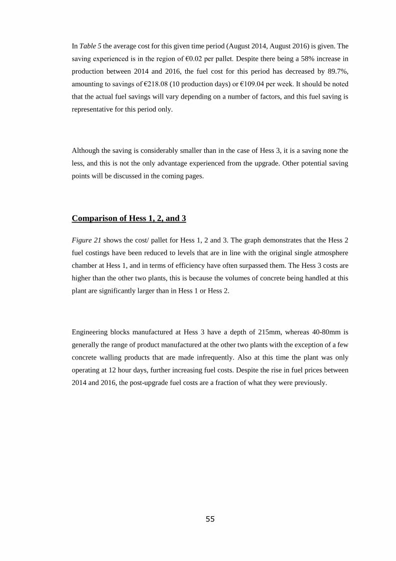
55
In Table 5 the average cost for this given time period (August 2014, August 2016) is given. The
saving experienced is in the region of €0.02 per pallet. Despite there being a 58% increase in
production between 2014 and 2016, the fuel cost for this period has decreased by 89.7%,
amounting to savings of €218.08 (10 production days) or €109.04 per week. It should be noted
that the actual fuel savings will vary depending on a number of factors, and this fuel saving is
representative for this period only.
Although the saving is considerably smaller than in the case of Hess 3, it is a saving none the
less, and this is not the only advantage experienced from the upgrade. Other potential saving
points will be discussed in the coming pages.
Comparison of Hess 1, 2, and 3
Figure 21 shows the cost/ pallet for Hess 1, 2 and 3. The graph demonstrates that the Hess 2
fuel costings have been reduced to levels that are in line with the original single atmosphere
chamber at Hess 1, and in terms of efficiency have often surpassed them. The Hess 3 costs are
higher than the other two plants, this is because the volumes of concrete being handled at this
plant are significantly larger than in Hess 1 or Hess 2.
Engineering blocks manufactured at Hess 3 have a depth of 215mm, whereas 40-80mm is
generally the range of product manufactured at the other two plants with the exception of a few
concrete walling products that are made infrequently. Also at this time the plant was only
operating at 12 hour days, further increasing fuel costs. Despite the rise in fuel prices between
2014 and 2016, the post-upgrade fuel costs are a fraction of what they were previously.

56
Figure 21 - Graph Showing Fuel Costs for Hess 1, 2, and 3 in 2014 and 2016.
It has proven difficult to accurately compare fuel costing throughout an entire production year
due to varying levels of production and changes in working hours in each plant. For this reason
the verification of savings has taken the form of multiple ‘snapshots’ of data from the
production year, trying as far as practicable to compare ‘like for like’ in terms of hours worked,
time of year, and layers produced per shift. Despite the variances in savings, the data has shown
consistently that the curing cost per pallet is significantly lower than pre-modernisation levels
despite increased production levels.
4.2 Effect on Production
In this section the main focus will switch to the Hess 2 plant. With each plant encountering its
own unique set of problems, product throughput was always the ‘Achilles heel’ of the curing
set-up at Hess 2, in the same way as Fuel Usage was the main issue at Hess 3.
Due to an expanding customer base, both domestically and in the UK, production levels at the
site have generally increased steadily since the Hess 1/ Schindler Plant was commissioned in
2008. As we have discussed in previous chapters, the demand for product that has received
0.000
0.050
0.100
0.150
0.200
0.250
0.300
Day 1 Day 2 Day 3 Day 4 Day 5 Day 6 Day 7 Day 8 Day 9 Day 10
Cu
rin
g C
ost
/ P
alle
t (€
)
Production Days
Typical Curing Cost/ Pallet- 2014 & 2016- Hess 1, 2, 3
Hess 1- 2016
Hess 2- 2014
Hess 2- 2016
Hess 3- 2014
Hess 3- 2016
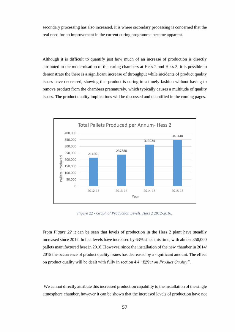
57
secondary processing has also increased. It is where secondary processing is concerned that the
real need for an improvement in the current curing programme became apparent.
Although it is difficult to quantify just how much of an increase of production is directly
attributed to the modernisation of the curing chambers at Hess 2 and Hess 3, it is possible to
demonstrate the there is a significant increase of throughput while incidents of product quality
issues have decreased, showing that product is curing in a timely fashion without having to
remove product from the chambers prematurely, which typically causes a multitude of quality
issues. The product quality implications will be discussed and quantified in the coming pages.
Figure 22 - Graph of Production Levels, Hess 2 2012-2016.
From Figure 22 it can be seen that levels of production in the Hess 2 plant have steadily
increased since 2012. In fact levels have increased by 63% since this time, with almost 350,000
pallets manufactured here in 2016. However, since the installation of the new chamber in 2014/
2015 the occurrence of product quality issues has decreased by a significant amount. The effect
on product quality will be dealt with fully in section 4.4 “Effect on Product Quality”.
We cannot directly attribute this increased production capability to the installation of the single
atmosphere chamber, however it can be shown that the increased levels of production have not
214561237880
313024
349448
0
50,000
100,000
150,000
200,000
250,000
300,000
350,000
400,000
2012-13 2013-14 2014-15 2015-16
Pal
lets
Pro
du
ced
Year
Total Pallets Produced per Annum- Hess 2

58
led to decreased product quality issues. This link between increased productivity and improved
quality demonstrates that the chambers are effectively carrying out the task for which they were
designed, curing large quantities of wet product in reduced times, all the while attaining high
standards of quality, a production state which was unattainable with the chamber set-up in 2014.
Prior to the installation of the new chamber, product quality at the Hess 2 plant suffered as a
result of fresh product being removed from the curing racks prematurely to make room for more
incoming product to allow manufacturing to continue. The poor turnaround rate of the semi-
open curing chamber previously in use forced operators to remove product with barely enough
early-strength and durability to allow the product to be packaged and removed from the plant.
With the new chamber, product is being cured in a timely fashion and is highly capable of
matching the production capabilities of the concrete block making machine at this plant in terms
of pallets/ hour (up to 250/ hour is normal). Although it is difficult to put a figure on this
chamber characteristic, it is fair to say that the design of the chamber has indeed exceeded the
group’s expectations in terms of throughput capability and has removed the issue of
‘bottlenecking’ at the Hess 2 plant.
4.3 Effect on Recipes
As discussed in the Literature Review, there is a number of benefits of using GGBS as a cement
replacement in concrete recipes, including;
o Reduced Cost.
o Reduced Environmental Impact.
o Lighter Colour
In this section we will discuss the implications a controlled curing programme has in terms of
recipe changes. The recipe, designed by the group’s Technical Department dictate the type and
quantity of each ingredient included in a concrete mix. Each paving product manufactured at
the site will have its own unique recipe, giving each product its characteristic colour,
appearance, strength and texture. By referencing production records it will be possible to
quantify the actual monetary saving on a typical production day at the Hess 3 plant.

59
In this scenario, a typical production day at Hess 3 is being described. The plant on this given
day is manufacturing standard 440 x 215 x 100mm engineering blocks, traditionally referred to
as 4” solid blocks. The savings resulting from using GGBS will be calculated and quantified.
The calculation will be based on an 18-hour working day (2x 9-hour shifts), the block machine
will typically operate for between 16 and 17 hours, allowing for cleaning time at the end of the
shift and will manufacture up to 3,500 layers of blocks, consisting of 24 blocks per layer. In
terms of production, engineering blocks are the mainstay of the Hess 3 plant and so were chosen
as the subject of any savings calculations.
In order to make the necessary volumes of concrete used to manufacture its blocks, a large
counter-flow type mixer is used with a capacity of 3mᶾ, approximately 4500kg of aggregates
will constitute a full batch. The mix cycle is approximately 120 seconds. At the start of the
cycle the 4500kg batch of different aggregates which have been pre-weighed are introduced
into the mixer from a holding hopper. The aggregates are blended together before the addition
of the binding agent (cement), which consists of a combination of RHPC and GGBS. Pigment
may be added to some engineering blocks (different colours denote different strength
categories).
Admixture is batched in a weigh vessel before being introduced at the appropriate stage,
followed by the addition of water and the final mixing stage which blends the concrete mix to
a homogenous state before being discharged into a holding hopper ready to be conveyed to the
block machine as required. In this example we will assume that 300 batches over the 18 hour
shift are required to produce the necessary quantity of concrete for the level of production on
the given day.
Although it is slightly smaller than the model operating at the Hess 3 plant, Figure 23 is a good
representation of the 3000 litre Danish-built, Haarup Counter-flow Mixer in operation there.
Note the labels on the image showing the cement weigh vessel and admixture weigh vessel.
RHPC and GGBS are conveyed into the cement weigh vessel via screw conveyor until the
recipe set-point has been reached, in this instance 300kg. The vessel hangs freely from a strain
gauge load cell, accurately weighing the contents of the vessel as cement is added. The weigh
vessel is calibrated on an annual basis to ensure accuracy. When the control system request the
addition of the pre-weighed RHPC and GGBS, an electrically or pneumatically-actuated

60
butterfly valve will open and allow the contents to flow out of the weigh vessel and into the
mixer via gravity. The cement is now thoroughly blended by the rotating mixing shovels within
the mixing pan before the addition of the pigment, water and admixtures.
After having given a brief explanation of the mixing cycle and describing the weighing and
addition of the binding agents, namely RHPC and GGBS, we can now begin to quantify the
actual cost savings attributed to the reduction of RHPC batched volume and the addition of
GGBS as a RHPC substitute. This process will consist of two sections. The first section will
show the old recipe structure as well as costs (pre chamber modernisation) Table 6 and the
second section will describe the changes that have been made to the recipe as well as any noted
savings (post chamber modernisation) Table 7.
Figure 23 - Danish built Haarup counter-flow mixer, similar to model used at Hess 3.
(Haarup.com)
Strain Gauge
Load Cell
Admixture
Weigh Vessel
Cement Screw
Conveyor
Cement Weigh
Vessel
3000 Litre
Mixing Pan
Concrete
Discharge Hopper
Water Weigh
Vessel

61
Pre-Modernisation Recipe (Cement Content)
Pre-Modernisation Recipe (Cement)
Cement Type RHPC GGBS
Mass of Cement per Mixing Cycle
300kg 0kg
Cost of Cement per Tonne
€ 95 € 65
Cost of Cement Per Mixing Cycle
€ 28.50 € -
Total Mass (300 Mixing Cycles)
90,000kg 0kg
Total Cost (300 Mixing Cycles)
€ 8,550 € -
Total Cement Cost per Day
€ 8,550
Table 6 - Pre-Modernisation Cement Recipe Statistics.
Post-Modernisation Recipe (Cement Content)
Table 7 - Post-Modernisation Cement Recipe Statistics.
Pre-Modernisation Recipe
Cement Cost (per Day)
€ 8,550
Cement Cost (per Week)
€ 42,750
Cement Cost per Pallet (3500 Pallet
Basis) € 2.44
Post-Modernisation Recipe (Cement)
Cement Type RHPC GGBS
Mass of Cement per Mixing Cycle
156kg 104kg
Cost of Cement per
Tonne € 95 € 65
Cost of Cement Per Mixing Cycle
€ 14.82 € 6.76
Total Mass (300 Mixing
Cycles) 46,800kg 31,200kg
Total Cost (300 Mixing
Cycles) € 4,446 € 2,028
Total Cement Cost per Day
€ 6,474
Post-Modernisation Recipe
Cement Cost (per Day)
€ 6,474
Cement Cost (per Week)
€ 32,370
Cement Cost per Pallet (3500 Pallet Basis)
€ 1.85
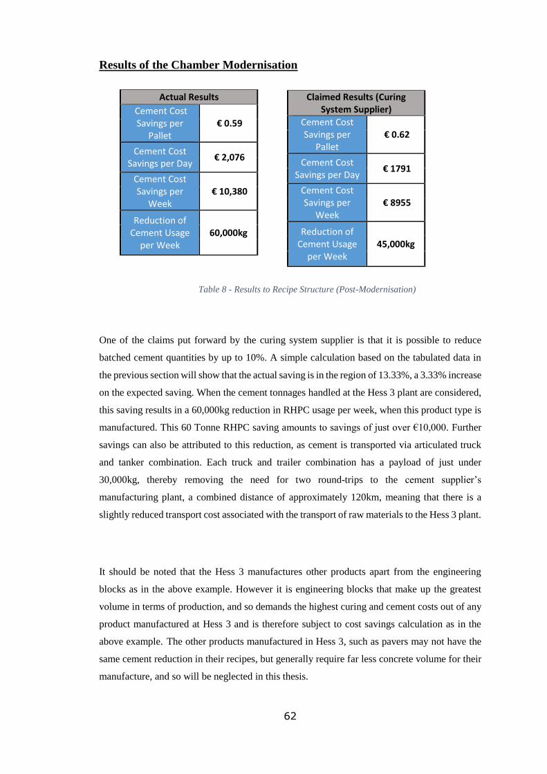
62
Results of the Chamber Modernisation
Actual Results
Cement Cost Savings per
Pallet € 0.59
Cement Cost Savings per Day
€ 2,076
Cement Cost Savings per
Week € 10,380
Reduction of Cement Usage
per Week 60,000kg
Table 8 - Results to Recipe Structure (Post-Modernisation)
One of the claims put forward by the curing system supplier is that it is possible to reduce
batched cement quantities by up to 10%. A simple calculation based on the tabulated data in
the previous section will show that the actual saving is in the region of 13.33%, a 3.33% increase
on the expected saving. When the cement tonnages handled at the Hess 3 plant are considered,
this saving results in a 60,000kg reduction in RHPC usage per week, when this product type is
manufactured. This 60 Tonne RHPC saving amounts to savings of just over €10,000. Further
savings can also be attributed to this reduction, as cement is transported via articulated truck
and tanker combination. Each truck and trailer combination has a payload of just under
30,000kg, thereby removing the need for two round-trips to the cement supplier’s
manufacturing plant, a combined distance of approximately 120km, meaning that there is a
slightly reduced transport cost associated with the transport of raw materials to the Hess 3 plant.
It should be noted that the Hess 3 manufactures other products apart from the engineering
blocks as in the above example. However it is engineering blocks that make up the greatest
volume in terms of production, and so demands the highest curing and cement costs out of any
product manufactured at Hess 3 and is therefore subject to cost savings calculation as in the
above example. The other products manufactured in Hess 3, such as pavers may not have the
same cement reduction in their recipes, but generally require far less concrete volume for their
manufacture, and so will be neglected in this thesis.
Claimed Results (Curing System Supplier)
Cement Cost Savings per
Pallet € 0.62
Cement Cost Savings per Day
€ 1791
Cement Cost Savings per
Week € 8955
Reduction of Cement Usage
per Week 45,000kg

63
4.4 Effect on Quality
The group’s philosophy is based on supplying Irish manufactured premium product at
affordable prices. It is only fair to mention that for the vast majority of cases, any product
suffering from quality issues that may be directly attributed to the pre-modernisation curing
practices at the site have generally never made it as far as the customer, due to the company’s
rigorous quality control program. Any product manufactured which may exhibit any of these
quality issues are removed from the production line before ever making it to customers hands,
and make up the ‘waste’ portion of the production run. This product wastage has the unfortunate
effect of increasing the production cost, as greater volumes of product must be manufactured
to replace this wastage ensuring that customer demands for product are still met.
Figure 24 - Graph showing occurrences of internal quality control issues, 2014 vs. 2016.
Figure 24 graphically illustrates the occurrences of internal quality control issues in the year of
2014 and 2016. The five main quality issues listed result from ‘less than ideal’ curing practices.
Internal Quality Issues are typically quality complaints that are flagged internally by factory
operatives or technical operative during manufacture or processing. Typically products
exhibiting these ‘issues’ are removed from the production line and make up the product ‘waste’
factor. The five issues listed are discussed in greater detail in the next section.
25
510
1
57
20
32
9
2 00
10
20
30
40
50
60
2014 2016
Inte
rnal
Pro
du
ct Q
ual
ity
Issu
es
Date
Internal Product Quality Issues- 2014 vs. 2016
Efflorescence
Breakages
Surface Finish
Colour variation
Ravelling

64
Five Main Quality Defects Associated with Curing Practices
Concrete paving products, regardless of where in the world they are manufactured are prone to
certain product quality issues that may influence the final strength, colour, texture and
appearance of the final product. However, only certain quality issues may be linked with the
curing practice at the place of manufacture. Some of these issues are listed below. Referring to
Figure 24 we will quantify the actual numerical improvement in each case.
o Primary and Secondary Efflorescence- Since the commissioning of the Hess 2 and
Hess 3 single atmosphere chambers, incidences of primary and secondary efflorescence
have been greatly reduced, with over 25 incidences in 2014 dropping to just 5 in 2016,
an 80% reduction. Previously, despite the fact that efflorescence is not considered a
‘fault’ under European quality standards, efflorescence was by far the most common
customer complaint (external complaint). Secondary Efflorescence can take a number
of days and sometimes weeks to develop meaning it is extremely difficult to detect
during the quality control process, only becoming apparent after delivery or
installation.
o Product Breakages- Product is now emerging from the curing chambers with a
significantly larger proportion of potential early-strength now attained. It is now
possible to put 24-hour-old product through invasive secondary finishing processes.
Incidences of product breakages during secondary finishing is significantly reduced, as
product is now strong enough to receive shot-blasting, grinding, and other treatments
without disintegrating. Incidences of excessive product breakages have been reduced
from 10 in 2014 to just 1 in 2016, a reduction of 90%. It should be noted that a certain
quantity of breakages during surface treatment is deemed acceptable, the 10 incidences
refer to occasions when the level of breakages have reached unacceptable levels.
o Surface finishes- Surface finishes are now far more consistent, products entering
treatment processes are cured to the same extent, and so generally facilitate consistent
finishes, where previously, a mixture of fully and partially-cured products would be
treated together and a large finish variation would occur. Inconsistencies in product-
finish was yet another customer complaint, when laid at the customers site, the paving
would look poor aesthetically. Thankfully, inconsistencies in surface finish, owing to
poor curing methods, has been greatly reduced, with 57 incidences in 2014 down to
just 20 in 2016, a 64% reduction.
o Colour Variation- During the era of the semi-open curing chamber at the Hess 2 plant,
colour variation was a major complaint, particularly in lighter coloured products, e.g.

65
yellow. This was due to the large variations in temperature that existed within the
chambers. When the first pallets containing freshly made product were placed into an
empty curing rack, conditions inside the chamber at this time were less than ideal, the
rack door would be open to facilitate the filling of the remaining rack spaces meaning
that heat retention was poor. After approximately 2 hours of production, when the rack
has been completely filled, the rack door would be closed and the pre-set curing cycle
would begin. For the purposes of this explanation, it will be beneficial to give names
to certain pallet stacks within the chamber in order to better explain the curing process
experienced by each. The conditions experienced by the first set of pallets to enter the
chamber (Pallet Stack A) would be very different to the final set of pallets to enter the
chamber (Pallet Stack B). For example;
Curing Scenario for Pallet Stack A
Pallet Stack A is the first stack to enter the chamber. At this point the supply of heated
air to this chamber has been switched off. The rack door is open, allowing for the
remaining rack spaces to be filled. The exothermic reaction begins as the cement within
the product begins to hydrate. The conditions are less than ideal, the chamber is too
cold due to the damaged insulation within the chamber. The heat generated by the
hydration reaction escapes to atmosphere. The concrete begins to harden in these less
than ideal conditions. The colour retention properties of product contained in Stack A
are poor, other quality issue may occur. Product density will also be an issue.
Conversely, Stack B will experience a completely different set of circumstances.
Curing Scenario for Pallet Stack B
Pallet Stack B is the last stack to enter the chamber, the remaining rack spaces have
been filled. At this point the rack door is closed and the pre-set curing cycle begins.
The exothermic reaction begins as the cement within the product begins to hydrate. The
conditions are still less than ideal but are far more favourable than those experienced
by Stack A. The chamber slowly begins to fill with heated air, moisture is also
introduced. The heat generated by the hydration reaction slowly accumulates within

66
the curing atmosphere. The concrete contained within Stack B begins to cure in a
relatively warm and moist environment which accelerates the hydration process. The
concrete in Stack A is now two hours into its curing cycle and is only now starting to
be introduced to more favourable curing conditions.
The different curing states experienced by both pallet stacks mean that they will have
very different product characteristics. Colour retention, density and surface finish will
be far superior in Pallet Stack B when compared to Stack A. The difference in colour
retention is by far the most obvious consequence of the different sets of curing
conditions. This problems becomes obvious during the installation phase.
Since the installation of the single atmosphere (fully enclosed) chamber, incidences of
poor colour retention have been reduced from 32 in 2014 to just 9 in 2016, a reduction
of approximately 72%. It is fair to mention that the technology used in the manufacture
of more modern semi-open design curing chambers has improved vastly since the
installation of the original Hess 2 chambers in 1996, and any problems experienced at
the plant owing to the use of older technology were greatly exacerbated by general wear
and tear accumulated over its 20-year working life.
o Ravelling- Ravelling occurs when particles of aggregate are released from the surface
of concrete products. Ravelling often occurs during secondary processing, stones
within the surface of the concrete break free from their bond resulting in an aesthetically
poor finish. Incidences of concrete ravelling have decreased from 2 in 2014 to 0 in
2016. The improved curing regime offered by the fully enclosed chambers ensure that
surface density is greatly improved, virtually eliminating ravelling.
From the analysis of the above data it is evident that, in general product quality at the Hess 1,
2 and 3 plants has greatly improved since the newly refurbished chambers were commissioned.
Better understanding of the curing parameters within the chamber ensure that the Technical
Department continue to improve product quality at the site. It is evident that this increased
product quality which is noted falls in line with the curing system supplier’s claim.

67
5 Conclusion
In the final chapter the effects of the curing chamber modernisation process at the Hess 2 and
Hess 3 plants will be summarised and evaluated. It will be decided whether the benefits offered
by the new system outweigh the initial investment. Importantly, the claims put forward by the
supplier of the new curing chambers will also be verified.
Excessive fuel/ Energy Usage
The supplier of the newly commissioned single atmosphere curing chamber claim that their
product is “ideal for increasing the concrete quality while reducing curing costs by up to 50%”
[17]. It would be unfair to assume that every curing setup can yield savings as high as 50%, but
the table below shows the actual saving incurred in 2016 over the pre-modernisation year of
2014.
o In Hess 3 it was noted that there was a 15% increase in production between the first 10
production days in July 2014 (pre-modernisation era) and the same 10 days in July
2016 (post-modernisation era). Despite the increase in production levels, savings of
approximately €4500 were recorded for this 10 day period compared with the 2014 fuel
costs.
o In Hess 2 it was noted that there was a 58% increase in production between the first 10
production days in August 2014 (pre-modernisation era) and the same 10 days in
August 2016 (post-modernisation era). Despite the increase in production levels,
savings of approximately €218 were recorded for this 10 day period compared with the
2014 fuel costs.
Table 9 - Annual Calculated Savings- Hess 3 in 2016.
2014 2016 Savings
Heat Requirement
Kilowatt-hours
(kWh) 1,808,879 kWh 829,283 kWh
54%
Or
979,596 kWh
Fuel Cost to Supply
Heat Requirement €130,000 €32,929 €97,071

68
From Table 9 it is clear that the calculated savings in terms of energy usage have surpassed the
claims made by the curing system supplier by 4% for this particular year. This figure may not
be indicative of every production year, the system is still relatively new and 2016 was the first
full year of production to use the new chamber, future ongoing calculations will have to be
made to fully verify this result. Although, considering the data, the incurred savings are very
promising, with a reduction in fuel cost of €97,071 in Hess 3 alone.
For me, the results of the fuel saving calculation were not surprising. The true energy
requirement of the old system was extreme to say the least, especially when it is compared to
the more frugal modern design of the single atmosphere chamber. The enormous annual saving
will quash any doubts in the accounting department relating to the large initial investment of
the new system.
Production
It should be made clear that the designer of the new curing system does not claim to increase
productivity through the use of the new chamber, as the chamber should be designed to meet
the production capability of the plant into which it is integrated. However. It can be shown that
the new system is more than capable of receiving increased quantities of product with a reduced
cost, all the while maintaining elevated levels of product quality. The newly improved chamber
has surpassed the group’s expectations in terms of expected throughput, allowing a reduced
turnaround rate, just 8 hours for some products with no adverse quality effects, which is a vast
improvement on the old set-up which struggled to match the production capabilities of their
respective plants and turned out defective product as a result (discussed in greater detail in the
coming pages).Product throughput in 2016 is up by 63% compared with pre-modernisation
levels, despite this increase, frequency of poor product quality has decreased by 81%. There are
many factors that influence the rate of production, but the quick turnaround provided by the
new single atmosphere units has helped to make such a large increase possible.
In my opinion quantifying production levels has been one of the more difficult aspects of the
thesis. Production levels have varied significantly over the last few years at the Hess 3 plant
when compared with the other two plants on site, making it difficult to reach reliable and valid
conclusions without extrapolation.

69
Recipes
The controlled curing programme has seen the strength of blocks produced at Hess 3 rise by a
considerable amount. From the onset of the chamber commissioning this was evident. Ongoing
strength tests are carried out during production runs to ensure that engineering blocks comply
with their stated strength rating e.g. 7.5, 10, 15 and 20 Newton/mm² etc. Upon investigation by
the Technical Department it was found that a considerably higher percentage of the products
potential early-strength was being achieved in same or reduced curing duration when compared
to the pre-modernisation era. This meant that cement quantities within the recipe could be
reduced all the while ensuring the necessary strength is still being achieved, also allowing for
a considerable ‘safety’ margin meaning that product is typically well above the minimum
strength threshold. This reduction in cement usage lead to the monetary saving which is
discussed in greater detail in the Results section.
Figure 25 - Graph of Strength Analysis 2014 vs. 2016.
(Company Report)
0.0
2.0
4.0
6.0
8.0
10.0
12.0
14.0
16.0
N/
mm
²
Date
Strength Analysis 2014 vs. 2016
TARGET MEANSTRENGTH
AVERAGE
LOWER LIMIT
ACTION POINT =CHAR + 5%
RUNNING MEANOF 4
Post-ModernisationPre-Modernisation

70
Figure 25 is a graph which plots the mean strength (N/mm²) of a sample of four blocks removed
from the production line. This sampling is taken at regular intervals throughout the day. The
sample undergoes a series of quality tests, one of which is compressive strength, and this is the
test with which we are concerned with. The recorded strength of each sample is plotted against
a number of critical thresholds contained on the graph which describe minimum allowable
limits etc. The red coloured trend line is the mean compressive strength of the four samples
taken. The area of the graph to the left hand side of the dashed line represent sample taken pre-
modernisation and the area to the right represent samples taken post modernisation.
It is evident that the strength of the sample drastically increases after the single atmosphere
curing chamber is commissioned. The ‘Running Mean Strength’ is also far more consistent
when compared with the undulating trend line in the left portion of the graph. It was this
‘excessive strength’ in the post-modernisation region which allowed the Technical Department
to reduce the quantity of cement within the recipe while still retaining a comfortable safety
margin in terms of strength. The curing system supplier claims that it is possible to reduce
cement usage by as much as 10% [5]. It is now possible to verify this claim by analysing the
data that is presented. In the Hess 3 plant the installation of the single atmosphere curing
chamber meant that it was now possible to manufacture concrete using GGBS alongside a
reduced RHPC batch size.
o Large reduction in RHPC usage now possible as cheaper and more environmentally
friendly GGBS would now replace up to 40% of RHPC content in certain recipes.
o Reduction in RHPC usage resulted in potential savings in excess of €10,000 per week,
based on 18-hour, 5 day week, and manufacturing 100mm 7.5N engineering blocks.
Up to 60,000kg of RHPC can now be saved per week using the post-modernisation
recipe.
Table 10 - Annual Projected Cement Savings, Hess 3.
Based on the exclusive manufacture of 7.5N 100mm solid engineering blocks at the
Hess 3 plant over a 48 week, 5 days per week 12,000 pallet per week basis.
Annual Projected Cement Savings
This value is based on the reduction of RHPC and the increased use of GGBS

71
Table 11 - Weekly Recipe Savings and Annual Projected Savings- Hess 3, 2016.
Table 10 depicts annual projected savings based on Hess 3 solely manufacturing 7.5N 100mm
solid engineering blocks over a 48 week production year. Although this is not a fair
representation of what is being manufactured at Hess 3 in recent times, it does show the
potential savings which are possible under certain attainable conditions.
Table 11 summarises the actual savings that are possible with the implementation of the
controlled curing program. Actual cement savings are in the region of 13% on some recipes
(440 x 215 x 100mm, 7.5N Engineering Block), surpassing the 10% expectation put forward
by the supplier, allowing potential savings of up to €10,380 per week.
Another surprising result for me. I never considered the true scope of the potential saving
resulting from the use of GGBS in recipes. The value of RHPC reduction in combination with
increased GGBS usage resulted in a substantial saving. Even with the overall cement reduction,
the Technical Department are continually impressed with the well-above-average strength
characteristics of product manufactured at Hess 3.
Weekly Recipe Savings
Cement Cost Savings per
Pallet
€ 0.59
Cement Cost Savings per Day
€ 2,076
Cement Cost Savings per
Week € 10,380
Reduction of Cement Usage
per Week 60,000kg

72
Quality
One of the main benefits of the single atmosphere curing chamber is the effect the controlled
curing regime has on product quality. In the results section the five main defects associated
with poor curing practices were detailed. Provided in the following list is a recap of these five
defects, and the percentage value by which the occurrence of each has been reduced.
Defect Type Percent Reduction
(Internal Complaints)
Primary and Secondary
Efflorescence 80%
Product Breakages 90%
Surface Finish 64%
Colour Variation 72%
Ravelling 100%
Table 12 - Annual - Percent Reduction of Internal Complaints
It is clear from the data contained in Table 12 that there has been a notable decrease in levels
of internal-complaint within the production facility. The average reduction across the five main
quality complaints is in the region of 81%. With some complaints being completely eliminated
since the commissioning of the new curing chamber. Increased product quality levels also have
the important effect of improving the firm’s reputation amid its expanding customer base. It is
difficult to put a price or quantity on reputation but its importance should not be underestimated,
especially with the company’s intentions to retain a UK-based market share.
From speaking to operators in the secondary processing plant, it is clear that the installation
of the single atmosphere chamber has made a significant difference to waste levels. Operators
claim that product is harder and better able to cope with a selection of secondary finishes, such
as shot-blasting and polishing. Issues with colour matching products made at Hess 2 have been
eliminated. This characteristic of the new chamber has proven very difficult to put a financial
value to, due to the massive selection of product type, colour, and finish, all of which demand
different market prices.
73
Concluding Remarks
At a figure close to €500,000, the decision to upgrade the curing chambers at the Hess 2 and
Hess 3 plants was one of the biggest investments made by the group since the commissioning
of their Wet-Cast Paving Plant in early 2010.
In this thesis, it was my intention to quantify the actual effects on production resulting from this
upgrade and compare the findings to the claims put forward by the designer and manufacturer
of the new curing chambers. During my research it became obvious that the decision to upgrade
benefitted the company in many more ways than expected, financially, environmentally and
commercially. In many instances the actual savings encountered surpassed the claims made by
the supplier, thereby cementing their position as one of the world’s leading innovators in curing
technology.
From my presentation and interpretation of the recorded data, it should be clear to all that the
decision to invest proved to be a savvy one, and should facilitate the production of high quality,
affordable concrete construction products for many years to come. The case studied I have
included confirms that the results are not unique to the site, with numerous customers
worldwide reaping the benefits of reduced production costs.
I have chosen this topic as the subject of my thesis with the aim of gaining a better
understanding of the curing process and the technology associated with it. Having spent so
many years attempting to understand the mechanical aspects of the production and processing
of concrete paving through my position as mechanical fitter within the firm, the science behind
concrete curing was something which did not feature much in my working day. It was good to
expand my knowledge base on the subject, with product quality aspect of the topic particularly
interesting.
I only hope that I have gone some ways to fairly represent the data and information that was
freely provided to me by both companies, both of whom I would like to thank for their ongoing
support in the writing of this thesis.

74
6 References
[1] “Ingress Protection,” [Online]. Available: http://www.dsmt.com/resources/ip-rating-
chart/. [Accessed 10th February 10].
[2] PCA, “Cement.org,” [Online]. Available: http://www.cement.org/for-concrete-books-
learning/concrete-technology/concrete-construction/drying-concrete-vs-curing-concrete.
[Accessed 20 November 2016].
[3] K. Curing, “Quadrix,” 2016. [Online]. Available: http://www.kraft-
systems.com/index.php/en/curing-systems/quadrix-en. [Accessed 10th December 2016].
[4] C. Magazine, “CPI-Worldwide.com,” 2015. [Online]. Available: https://www.cpi-
worldwide.com/us/journals/artikel/40539. [Accessed September 2016].
[5] K. C. Systems, “Why Control Curing?,” 2016. [Online]. Available: http://www.kraft-
systems.com/index.php/en/kraft/why-control-curing. [Accessed October 2016].
[6] b.-. International, “Curing designed to achieve a visibly better product quality,” 2013.
[Online]. Available: http://www.bft-
international.com/en/artikel/bft_Curing_designed_to_achieve_a_visibly_better_product_
quality_1704657.html. [Accessed 15 January 2017].
[7] G. Pavers, “History of Pavers,” 25th July 2011. [Online]. Available:
http://www.gopavers.com/history-of-pavers/. [Accessed 11th December 2016].
[8] Michael Kraft, “Quadrix- A Case For Better Curing,” Kraft Curing Systems Gmbh, 2016.
[9] K. C. S. Gmbh., “Consistent Climate for the Production,” CPI Magazine, no. 2, p. 116,
2015.
[1
0]
Ecocem, “Ecocem GGBS,” [Online]. Available: http://www.ecocem.ie/products/ecocem-
ggbs/. [Accessed 4th February 2017].
[1
1]
A. Balogh, “ND Readymix & Concrete Products Association,” [Online]. Available:
http://www.ndconcrete.com/article/using.html. [Accessed 4th February 2017].
75
[1
2]
Hanson, “Regen GGBS,” [Online]. Available:
http://www.hanson.co.uk/en/products/regen-ggbs. [Accessed 05th March 2017].
[1
3]
basf, “master-builders-solutions.basf.com,” [Online]. Available: https://www.master-
builders-solutions.basf.com.tr/en-tr/products/masterlife/1716. [Accessed 12 February
2017].
[1
4]
CHRYSO, “us.chryso.com,” [Online]. Available:
http://us.chryso.com/fiche.php?id=48650. [Accessed 12 February 2017].
[1
5]
C. Magazine, “Consistent Colors, Efflorescence Prevention and Cost Reduction,” CPI
Magazine, no. 6, pp. 2-6, 2015.
[1
6]
SEAI, “Comparison of Useful Energy Costs for Space Heating,” 1st October 2016.
[Online]. Available:
http://www.seai.ie/Publications/Statistics_Publications/Fuel_Cost_Comparison/Commer
cial_Fuel_Cost_Comparison.pdf. [Accessed 27th January 2017].
[1
7]
“Insulated Curing Chambers,” 2017. [Online]. Available:
http://www.kraftcuring.com/en/isolierte-haertekammern.aspx. [Accessed 18th March
2017].


![Illuminating OpenMP + MPI Performance€¦ · cpi-mpi.c:48 cpi-mpi.c:84 cpi-mpi.c:109 cpi-mpi.c:97 1.0% cpi-mpi [program] main main [OpenMP region O] MPI Finalize MPI Reduce Showing](https://static.fdocuments.in/doc/165x107/6022cc2b9a65990f6b41506f/illuminating-openmp-mpi-performance-cpi-mpic48-cpi-mpic84-cpi-mpic109-cpi-mpic97.jpg)