PLC & SCADA PPT
43
Introduction of SOFCON Sofcon a Channel Partner of Rockwell Automation in India. It offers Turn-key Automation projects, solutions & services to power, chemical, pharma, cement, energy, food, water management etc. industries for over 02 decades. Sofcon India Pvt. Ltd (Training Wing of Sofcon Group) is committed to Strengthen practical Knowledge of Engineers / Working Professionals / Technicians
-
Upload
rama-kant-sahu -
Category
Documents
-
view
10.303 -
download
129
Transcript of PLC & SCADA PPT
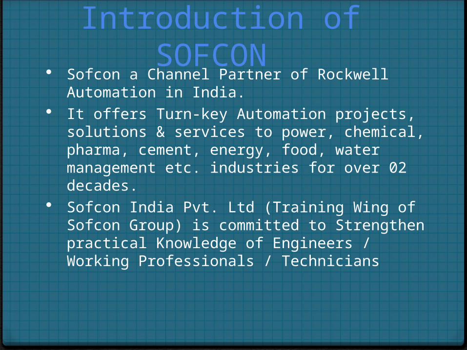
Introduction of SOFCON Sofcon a Channel Partner of Rockwell Automation in
India. It offers Turn-key Automation projects, solutions &
services to power, chemical, pharma, cement, energy, food, water management etc. industries for over 02 decades.
Sofcon India Pvt. Ltd (Training Wing of Sofcon Group) is committed to Strengthen practical Knowledge of Engineers / Working Professionals / Technicians
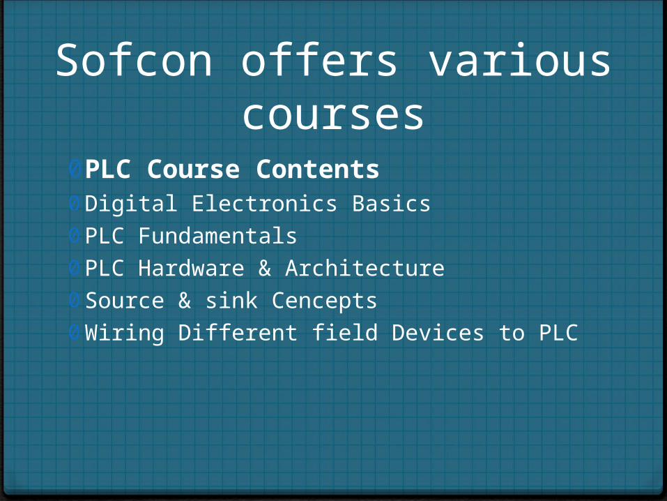
Sofcon offers various courses
0PLC Course Contents0 Digital Electronics Basics 0 PLC Fundamentals 0 PLC Hardware & Architecture 0 Source & sink Cencepts 0 Wiring Different field Devices to PLC
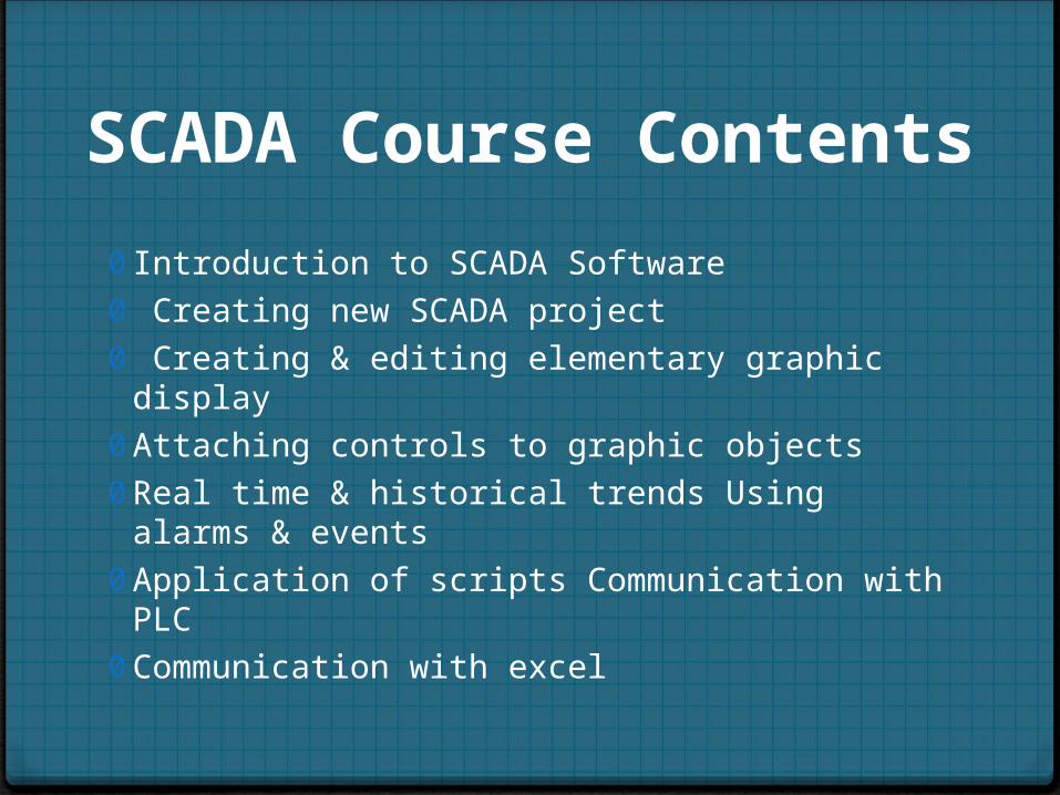
SCADA Course Contents
0 Introduction to SCADA Software0 Creating new SCADA project0 Creating & editing elementary graphic display 0 Attaching controls to graphic objects 0 Real time & historical trends Using alarms & events 0 Application of scripts Communication with PLC 0 Communication with excel
AUTOMATION
0 Automation is a step beyond mechanization.0 Automation is the use of control systems and
information technologies to reduce the need for human work in the production of goods and services.
Automation Components
0 Sensor for sensing physical conditions
0 Transmitters 0Control Systems0Output Devices
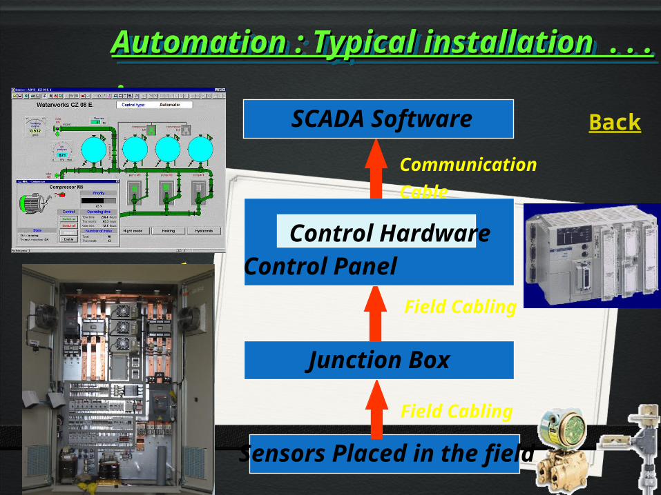
Sensors Placed in the field
Automation : Typical installation . . .Automation : Typical installation . . . .Automation : Typical installation . . .Automation : Typical installation . . . .
Junction Box
Field Cabling
Control Panel
Control Hardware
SCADA Software
Communication Cable
Field Cabling
Back
Programmable Logic Controllers
A PLC is a solid state / industrial computer that performs discrete or sequential logic in a factory environment.
It was originally developed to replace mechanical relays, timers, counters.
A sequence of instructions is programmed by the user to the PLC memory. Its purpose is to monitor crucial process parameters and adjust process operations accordingly.
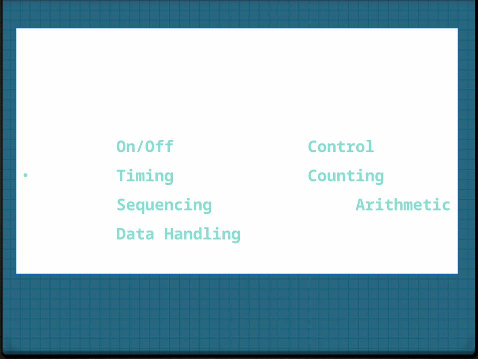
FUNCTIONS It controls output devices based on the status of inputs and a user written program. Originally developed to directly replace relays used for discrete control.It performs functions as
On/Off Control
• Timing Counting
Sequencing Arithmetic
Data Handling
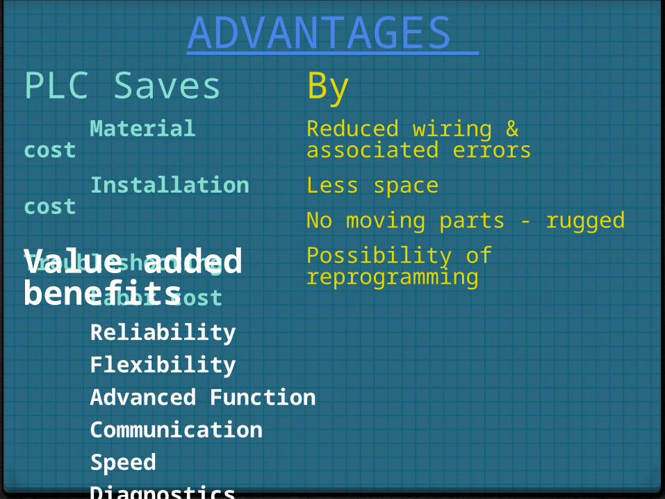
PLC SavesMaterial cost
Installation cost
Troubleshooting
Labor cost
ByReduced wiring & associated errors
Less space
No moving parts - rugged
Possibility of reprogramming
Value added benefitsReliability
Flexibility
Advanced Function
Communication
Speed
Diagnostics
ADVANTAGES
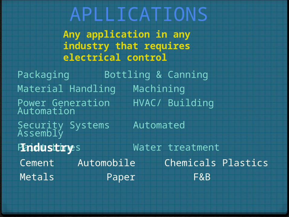
Packaging Bottling & Canning
Material Handling Machining
Power Generation HVAC/ Building Automation
Security Systems Automated Assembly
Paint Lines Water treatment
IndustryCement Automobile Chemicals Plastics
Metals Paper F&B
APLLICATIONS Any application in any industry that requires electrical control
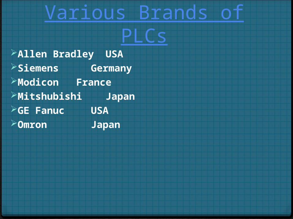
Various Brands of PLCsAllen Bradley USASiemens Germany Modicon FranceMitshubishi JapanGE Fanuc USAOmron Japan
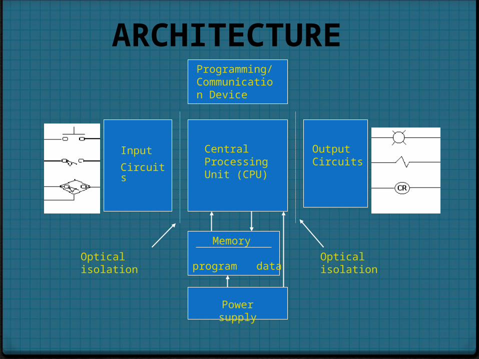
Programming/ Communication Device
Central Processing Unit (CPU)
Input
Circuits
Output Circuits
Memory
program data
Power supply
Optical isolation Optical isolation
ARCHITECTURE
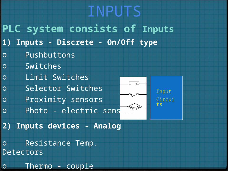
INPUTSPLC system consists of Inputs
Input
Circuits
1) Inputs - Discrete - On/Off type
o Pushbuttonso Switcheso Limit Switcheso Selector Switcheso Proximity sensorso Photo - electric sensors
2) Inputs devices - Analog
o Resistance Temp. Detectors
o Thermo - couple
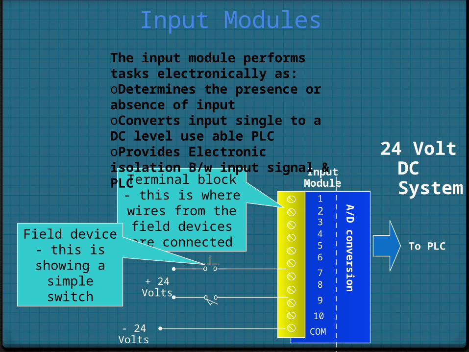
Input Modules
1
23456
78
9
10
COM
A/D
con
version
To PLC
Terminal block - this is where wires from the
field devices are connected
Field device - this is showing a simple
switch
Input Module
24 Volt DC System
+ 24 Volts
- 24 Volts
The input module performs tasks electronically as:oDetermines the presence or absence of input oConverts input single to a DC level use able PLCoProvides Electronic isolation B/w input signal & PLC
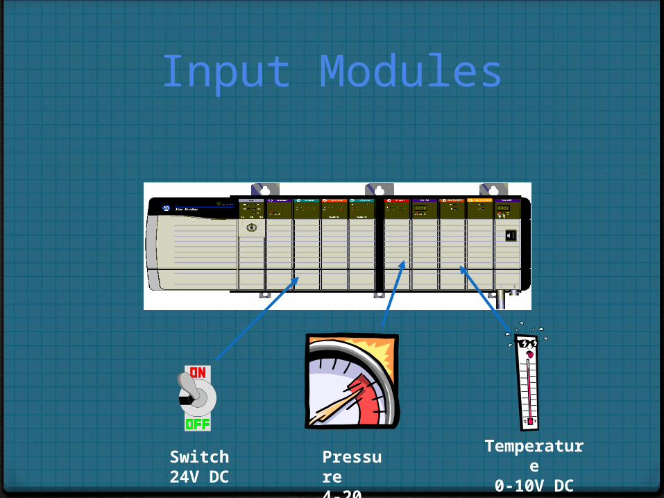
Input Modules
Pressure4-20 mA
Temperature0-10V DCSwitch
24V DC
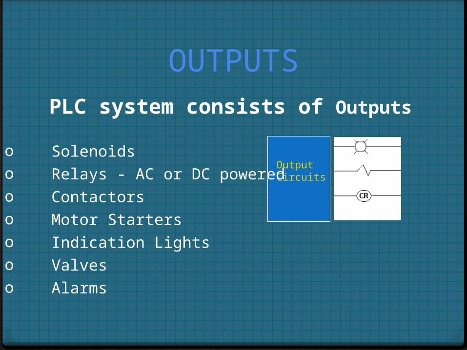
PLC system consists of Outputs
Output Circuits
o Solenoidso Relays - AC or DC poweredo Contactorso Motor Starterso Indication Lightso Valveso Alarms
OUTPUTS
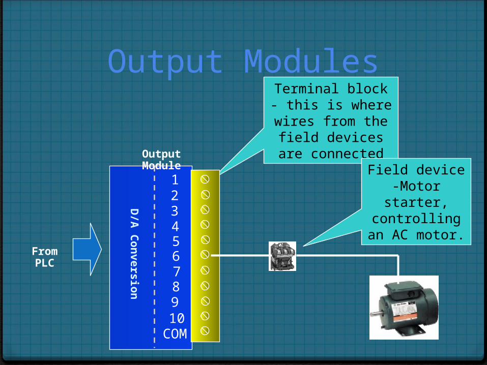
Output Modules
From PLC
Terminal block - this is where wires from the
field devices are connected
Field device -Motor starter, controlling
an AC motor.
12345678910
COMD
/A C
on
version
Output Module
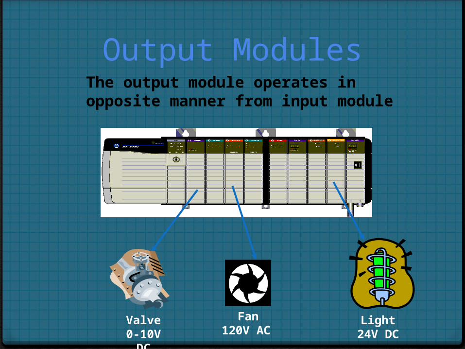
Output Modules
Fan120V AC
Light24V DC
Valve0-10V DC
The output module operates in opposite manner from input module
Processor, Controller, or CPU
Stores the control program and data in its memory Reads the status of connected input devices Performs Arithmetic and Logical Operations Executes the control program Commands connected outputs to change state based on
program execution
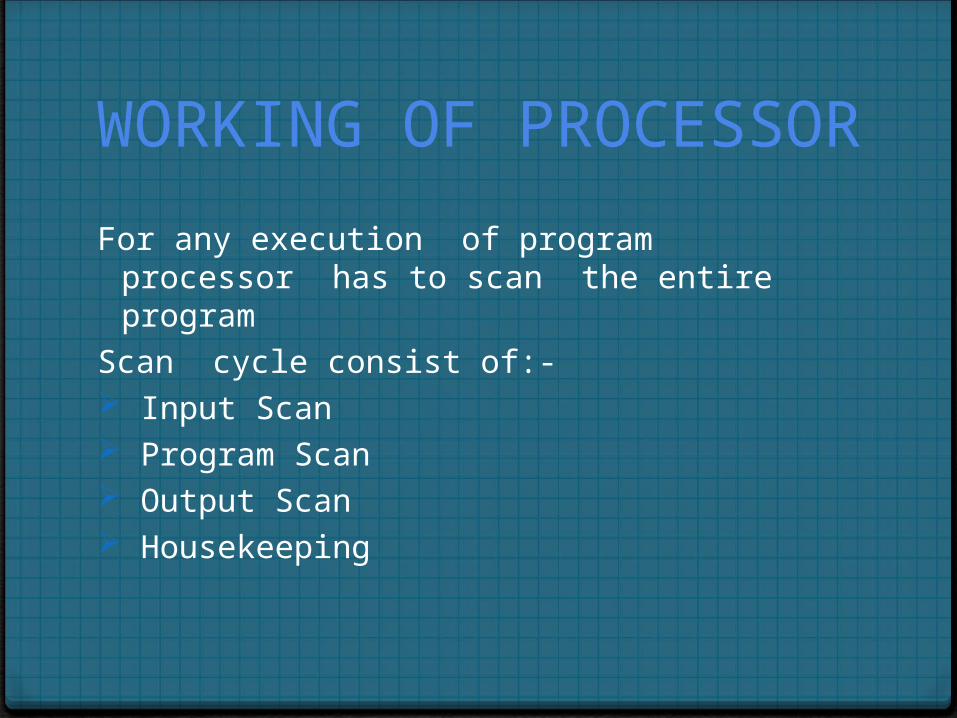
WORKING OF PROCESSOR
For any execution of program processor has to scan the entire program
Scan cycle consist of:- Input Scan Program Scan Output Scan Housekeeping
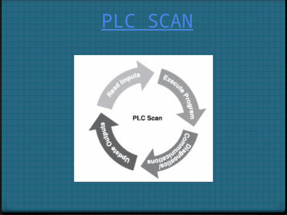
PLC SCAN
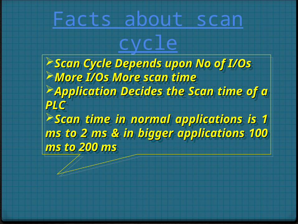
Facts about scan cycleScan Cycle Depends upon No of Scan Cycle Depends upon No of I/OsI/OsMore I/Os More scan timeMore I/Os More scan timeApplication Decides the Scan Application Decides the Scan time of a PLCtime of a PLCScan time in normal Scan time in normal applications is 1 ms to 2 ms & in applications is 1 ms to 2 ms & in bigger applications 100 ms to bigger applications 100 ms to 200 ms200 ms
Scan Cycle Depends upon No of Scan Cycle Depends upon No of I/OsI/OsMore I/Os More scan timeMore I/Os More scan timeApplication Decides the Scan Application Decides the Scan time of a PLCtime of a PLCScan time in normal Scan time in normal applications is 1 ms to 2 ms & in applications is 1 ms to 2 ms & in bigger applications 100 ms to bigger applications 100 ms to 200 ms200 ms
MEMORYThe processor consists of memory locations known as
wordsEach word can store binary data The number of bits that a word can store depends on the
system of PLCThe 16-bit word is more common
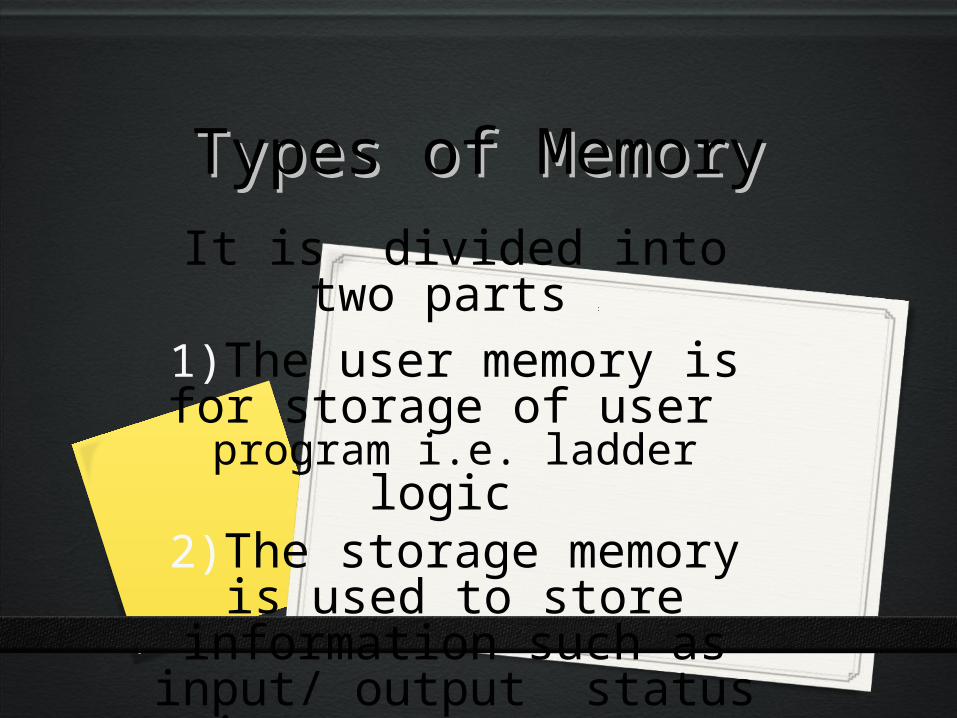
Types of MemoryTypes of MemoryIt is divided into two parts :
1)The user memory is for storage of user program i.e.
ladder logic 2)The storage memory is used
to store information such as input/ output status timers, or
counters
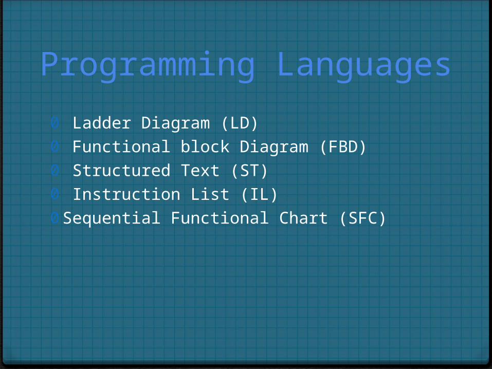
Programming Languages
0 Ladder Diagram (LD)0 Functional block Diagram (FBD)0 Structured Text (ST)0 Instruction List (IL)0 Sequential Functional Chart (SFC)
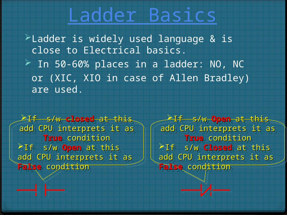
Ladder BasicsLadder is widely used language & is close to Electrical
basics. In 50-60% places in a ladder: NO, NC
or (XIC, XIO in case of Allen Bradley) are used.
If s/w If s/w closedclosed at this add at this add CPU interprets it as CPU interprets it as TrueTrue
conditionconditionIf s/w If s/w OpenOpen at this add at this add CPU interprets it as CPU interprets it as FalseFalse conditioncondition
If s/w If s/w closedclosed at this add at this add CPU interprets it as CPU interprets it as TrueTrue
conditionconditionIf s/w If s/w OpenOpen at this add at this add CPU interprets it as CPU interprets it as FalseFalse conditioncondition
If s/w If s/w OpenOpen at this add at this add CPU interprets it as CPU interprets it as TrueTrue
conditionconditionIf s/w If s/w ClosedClosed at this add at this add CPU interprets it as CPU interprets it as FalseFalse conditioncondition
If s/w If s/w OpenOpen at this add at this add CPU interprets it as CPU interprets it as TrueTrue
conditionconditionIf s/w If s/w ClosedClosed at this add at this add CPU interprets it as CPU interprets it as FalseFalse conditioncondition
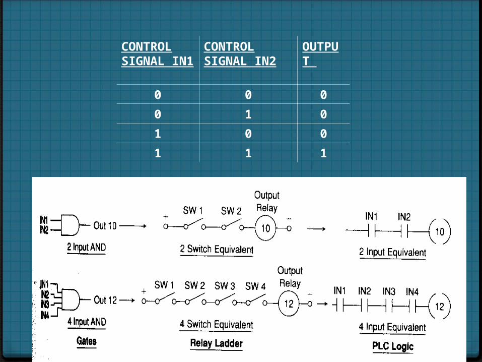
CONTROL SIGNAL IN1
CONTROL SIGNAL IN2
OUTPUT
0 0 0
0 1 0
1 0 0
1 1 1
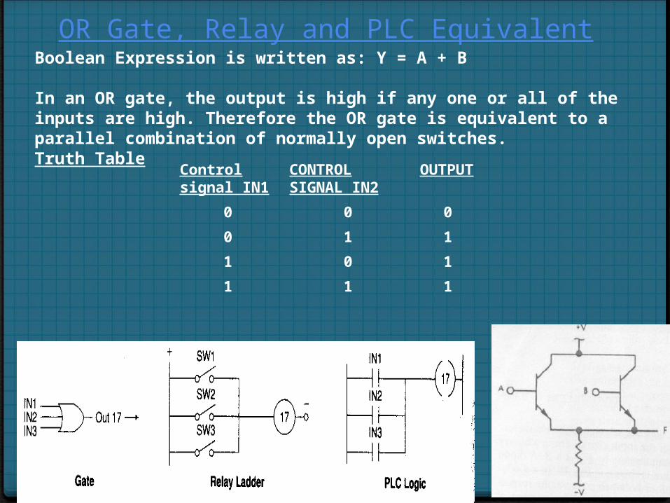
OR Gate, Relay and PLC Equivalent Boolean Expression is written as: Y = A + B
In an OR gate, the output is high if any one or all of the inputs are high. Therefore the OR gate is equivalent to a parallel combination of normally open switches.Truth Table
Control signal IN1
CONTROL SIGNAL IN2
OUTPUT
0 0 0
0 1 1
1 0 1
1 1 1
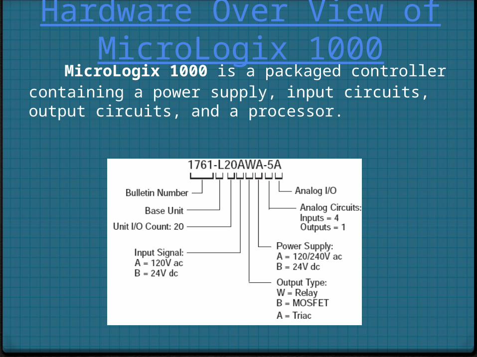
Hardware Over View of MicroLogix 1000
MicroLogix 1000 is a packaged controller containing a power supply, input circuits, output circuits, and a processor.
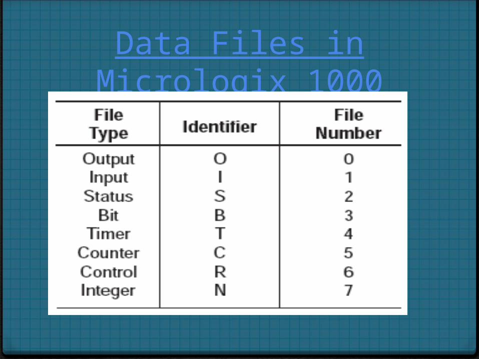
Data Files in Micrologix 1000
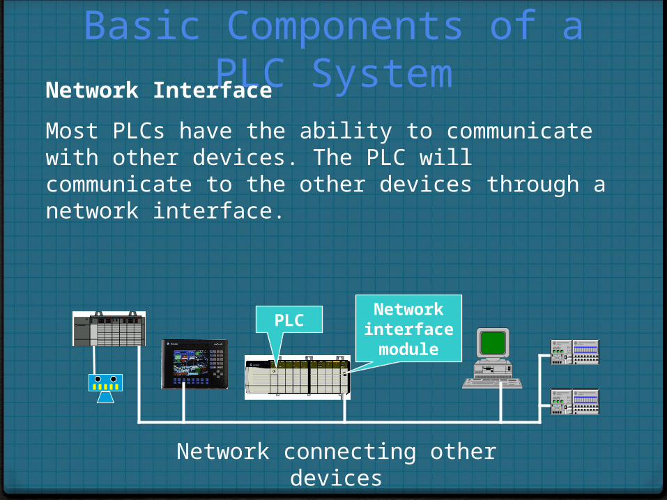
Basic Components of a PLC SystemNetwork Interface
Most PLCs have the ability to communicate with other devices. The PLC will communicate to the other devices through a network interface.
Network connecting other devices
Network interface module
PLC
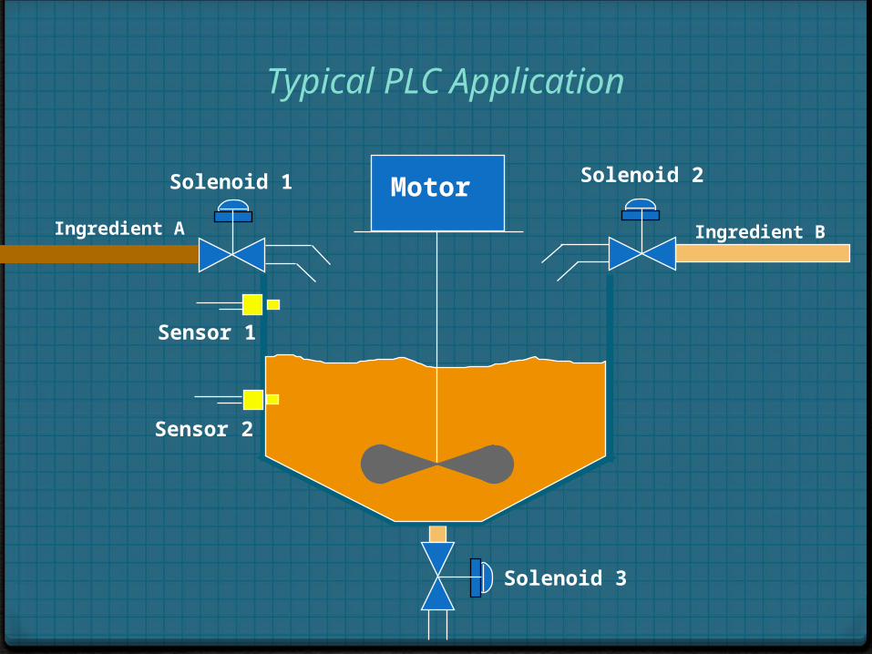
Typical PLC Application
Motor Solenoid 1 Solenoid 2
Solenoid 3
Sensor 1
Sensor 2
Ingredient A Ingredient B
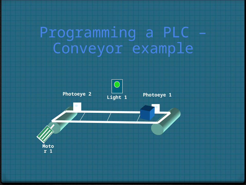
Programming a PLC – Conveyor example
Light 1Photoeye 2 Photoeye 1
Motor 1
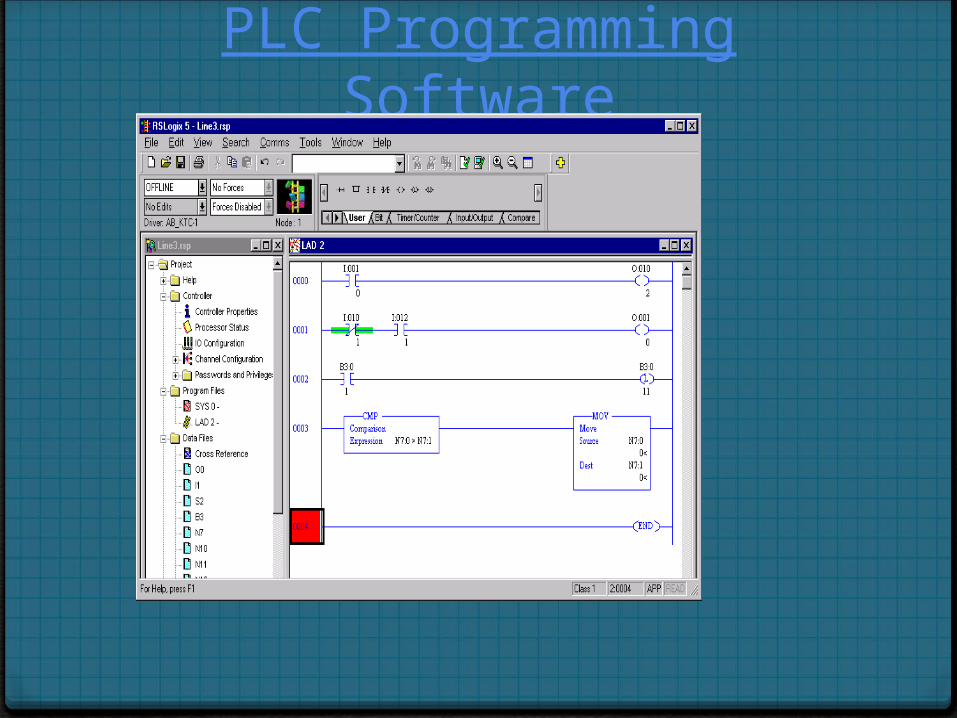
PLC Programming Software
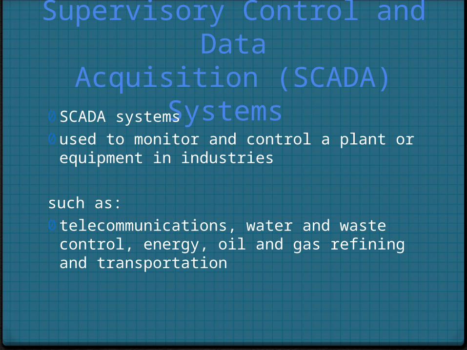
Supervisory Control and DataAcquisition (SCADA) Systems
0 SCADA systems0 used to monitor and control a plant or equipment in
industries
such as:0 telecommunications, water and waste control, energy,
oil and gas refining and transportation
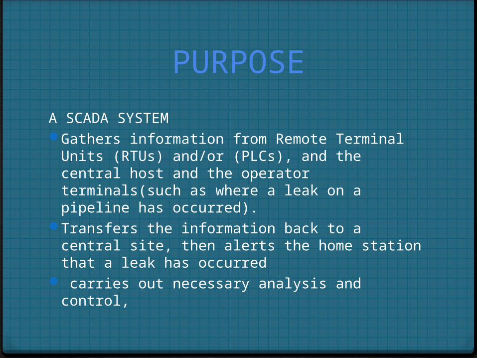
PURPOSE
A SCADA SYSTEM Gathers information from Remote Terminal Units
(RTUs) and/or (PLCs), and the central host and the operator terminals(such as where a leak on a pipeline has occurred).
Transfers the information back to a central site, then alerts the home station that a leak has occurred
carries out necessary analysis and control,
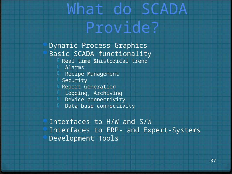
What do SCADA Provide?
Dynamic Process GraphicsBasic SCADA functionality
Real time &historical trend Alarms Recipe Management Security Report Generation Logging, Archiving Device connectivity Data base connectivity
Interfaces to H/W and S/WInterfaces to ERP- and Expert-SystemsDevelopment Tools
37
DEVICE CONNECTIVITY
Every manufacturer have there one way communication or follow different protocols.
SCADA S/W should have connectivity to different h/w used in automation
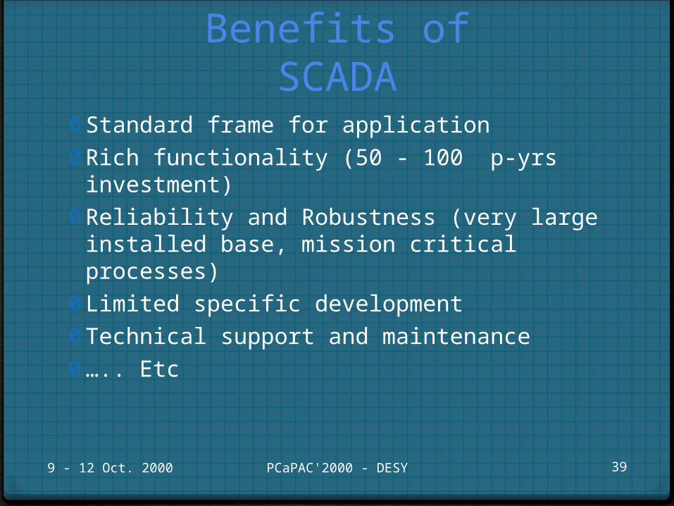
Benefits of SCADA
0 Standard frame for application 0 Rich functionality (50 - 100 p-yrs investment)0 Reliability and Robustness (very large installed base,
mission critical processes)0 Limited specific development 0 Technical support and maintenance0 ….. Etc
9 - 12 Oct. 2000 PCaPAC'2000 - DESY 39
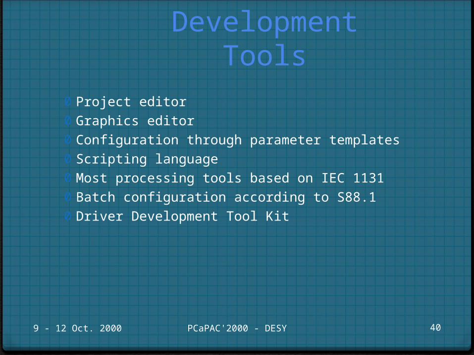
Development Tools
0 Project editor0 Graphics editor0 Configuration through parameter templates0 Scripting language0 Most processing tools based on IEC 1131 0 Batch configuration according to S88.10 Driver Development Tool Kit
9 - 12 Oct. 2000 PCaPAC'2000 - DESY 40
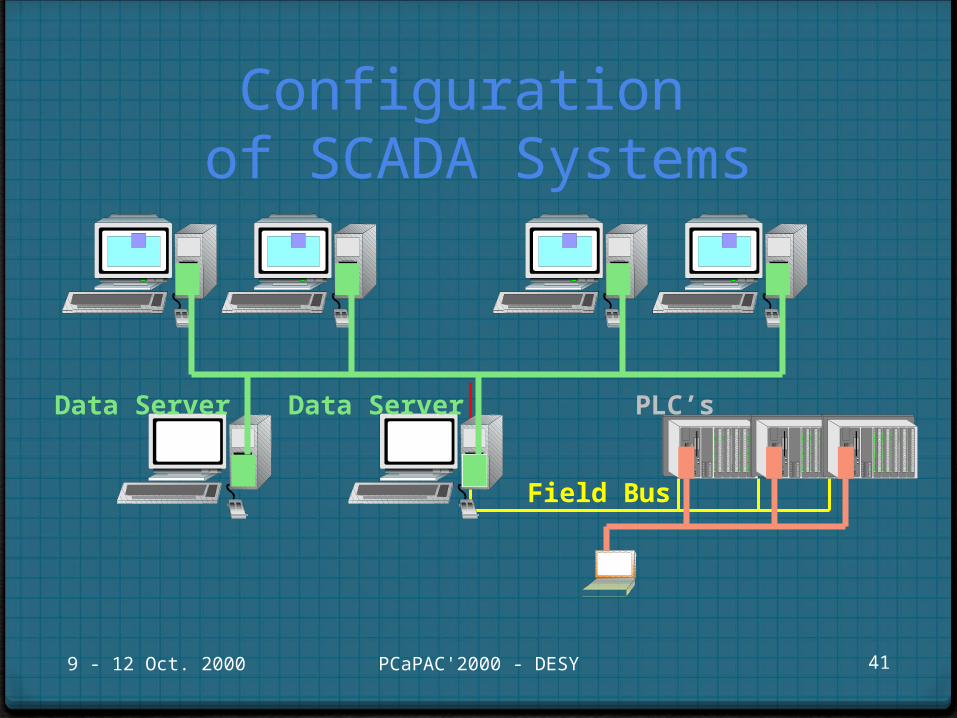
Configuration of SCADA Systems
9 - 12 Oct. 2000 PCaPAC'2000 - DESY 41
Field Bus
Data Server PLC’sData Server
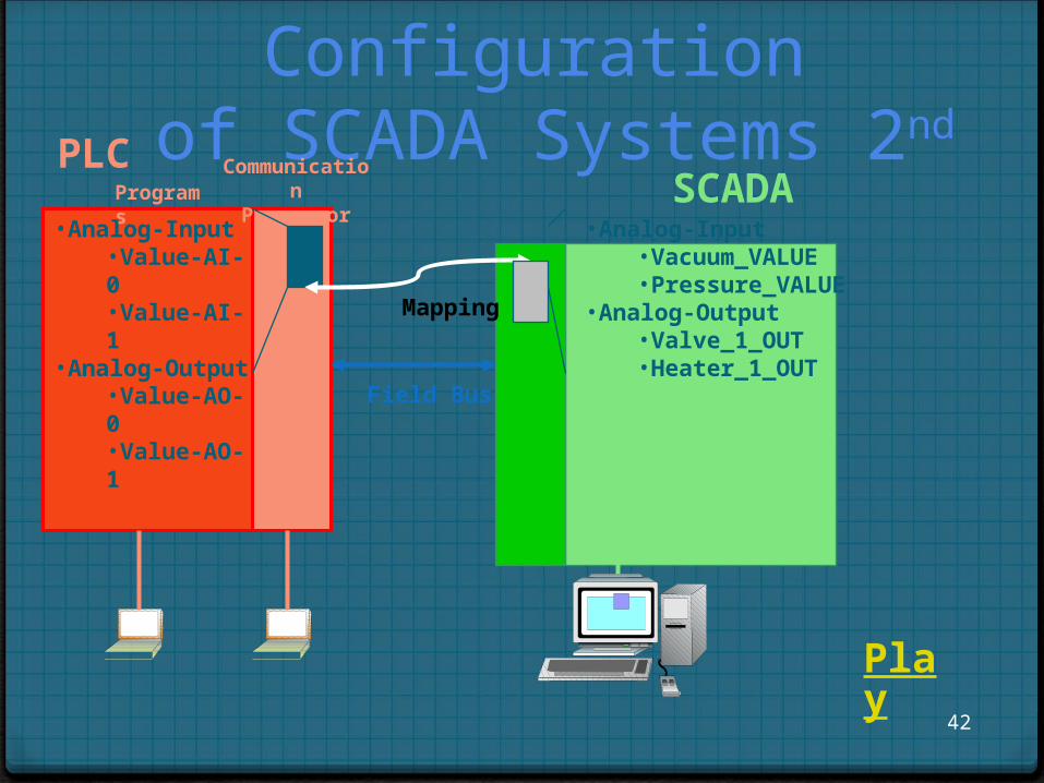
Configuration of SCADA Systems 2nd
42
PLCPrograms
CommunicationProcessor
•Analog-Input•Value-AI-0•Value-AI-1
•Analog-Output•Value-AO-0•Value-AO-1
Field Bus
•Analog-Input•Vacuum_VALUE•Pressure_VALUE
•Analog-Output•Valve_1_OUT•Heater_1_OUT
Mapping
SCADA
Play

THAT’S IT FROM THE PRESENTATION AREA
43
THANK YOU
THANK YOU