PLC Programming with RSLogix 500 - Industrial Automation · PDF fileIntroduction The purpose...
29
-
Upload
nguyenxuyen -
Category
Documents
-
view
229 -
download
2
Transcript of PLC Programming with RSLogix 500 - Industrial Automation · PDF fileIntroduction The purpose...

PLC Programming
with RSLogix 500
How to Program an Allen-Bradley PLC with Rockwell Automation’s
RSLogix 500
By Jack Rindell
Industrial Automation Series
engineer-and-technician.com
PLC Programming with RSLogix 500 Copyright © 2017 Modern Media & Automation, LLC
engineer-and-technician.com

Table of Contents
Introduction 1.....................................................................................PLCs 2...............................................................................................Hardware 3.........................................................................................SLC Rack 3........................................................................................SLC Power Supply 3..........................................................................SLC Processors 3..............................................................................SLC I/O Modules 4.............................................................................MicroLogix 1000 4..............................................................................MicroLogix 1200 4..............................................................................MicroLogix 1500 4..............................................................................Ladder Logic 5...................................................................................The Dialect of PLCs 5........................................................................Equivalent Logic 9..............................................................................Scan Time 10.......................................................................................Project Scope 11..................................................................................Summarizing the Scope 17..................................................................Which PLC? 18....................................................................................Lay Out The I/O 18...............................................................................Laying Out The Modules In The Rack 20.............................................Assigning I/O Addresses 21.................................................................Analog Inputs 21..................................................................................Digital Inputs 22...................................................................................Digital Outputs 23.................................................................................Installing RSLogix 24...........................................................................Installing RSLogix 500 24...................................................................Running RSLogix 25............................................................................Configuring Colors, Fonts and Address Display 31..............................Adding Descriptors To Your I/O 31.......................................................Writing the Program 34........................................................................Setting Up An Overall Control Rung 34................................................Starting a Batch Cycle 36.....................................................................Batching Steps 42................................................................................Step 1 – Adding City Water 42.............................................................Analog Inputs 45..................................................................................Setting Up an SCP to Calculate Tank Weight 48.................................Setting Up an SCP to Calculate Tank Level 50....................................Back to Batching – Step 1 51...............................................................Step 2 – Adding Chemical KM 54........................................................Step 3 – Adding Chemical KM 58........................................................Step 4 – Blending 59............................................................................Step 5 – Pump to Filling Lines 64........................................................Faults 66..............................................................................................
PLC Programming with RSLogix 500 Copyright © 2017 Modern Media & Automation, LLC
engineer-and-technician.com
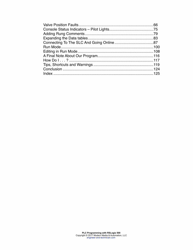
Valve Position Faults 66.......................................................................Console Status Indicators – Pilot Lights 75..........................................Adding Rung Comments 79.................................................................Expanding the Data tables 83..............................................................Connecting To The SLC And Going Online 87.....................................Run Mode 100........................................................................................Editing in Run Mode 108........................................................................A Final Note About Our Program 116.....................................................How Do I . . . ? 117................................................................................Tips, Shortcuts and Warnings 119.........................................................Conclusion 124......................................................................................Index 125...............................................................................................
PLC Programming with RSLogix 500 Copyright © 2017 Modern Media & Automation, LLC
engineer-and-technician.com
Introduction
The purpose of this book is to teach you how to set up, program and use an Allen-Bradley SLC 500 PLC. It will tell you what parts you need to buy for a common application.
It will tell you how to install RSLogix, how to write a ladder logic program, how to configure your computer and your SLC so that you can download your ladder logic program.
There is a sample project included that contains a Project Scope. The Project Scope (or Functional Specification, or whatever your company might call it) defines in detail how the system is to operate when the project is finished.
You will learn how to take a Project Scope and turn it into a working PLC program.
It will show you, step by step, how to go online with your SLC to monitor your program to verify your ladder logic and make sure it is functioning properly.
It will show you how to make changes to your program while you are online.
It will show you the keystrokes and mouse movements that you need to know to use RSLogix.
Finally, it provides a number of tips and a Frequently Ask Questions section that will save you hours of frustration.
This book assumes you have a little background with PLCs – perhaps you have worked with other PLCs from other manufacturers or you have helped to install and wire PLCs. Perhaps you are a Mechanical or Process Engineer and you need to learn how to use RSLogix.
If you need a more thorough understanding of basic PLC concepts, you might want to try the Beginner’s Guide to PLC Programming How to Program a PLC (Programmable Logic Controller). This ebook, along with the online tutorial, provides an example of how to automate a drill press, while explaining all the basic concepts of PLC programming that are necessary to write a solid PLC program.
The Beginner’s Guide to PLC Programming works well in conjunction with this book, in that it concentrates on basic PLC programming methods that are common to all types of PLCs. In addition, it provides an example of machine operation, whereas PLC Programming with RSLogix 500 uses the example of a chemical batching process.
Go to engineer-and-technician.com if you would like to learn more about this book.
PLC Programming with RSLogix 500 ! 1Copyright © 2017 Modern Media & Automation, LLC
engineer-and-technician.com
PLCs Nearly all the industrial equipment that you find in a modern manufacturing facility shares one thing in common - computer control. The most commonly used controller is the PLC, or the Programmable Logic Controller, using a programming language called Ladder Logic. The language was developed to make programming easy for people who already understood how switches, relay contacts and coils work. Its format is similar to the electrical style of drawing known as the “ladder diagram”.
The most popular and most widely used manufacturer of PLCs is Rockwell Automation, who produces the Allen-Bradley MicroLogix and SLC series of PLCs. The MicroLogix and SLC families of processors and I/O modules are all programmed using Rockwell’s proprietary software known as RSLogix.
In the book, we will concentrate specifically on the SLCs, MicroLogix PLCs and RSLogix. We won’t talk about other manufacturers or other Rockwell software, as RSLogix will (and currently does) perform nearly all the programming requirements of a plant’s automation system.
When you are finished with this book, you will be able to sit down in front of any computer running RSLogix and create a new program. You will be able to edit existing programs. You will be able to professionally document any changes you have made.
Rockwell Automation Technical Support
Unfortunately, we can’t anticipate all the problems you might face as you are troubleshooting a program on the factory floor. There are just too many variables. This is why you must establish a relationship with your local Rockwell Automation technical support team. Get to know them before you are in the final stages of a start-up and you run into a problem. They are very helpful and they can save you hours of frustration.
The Rockwell reps are not just technical support personnel; they are skilled engineers that are responsible for running their own projects and writing and troubleshooting their own programs. If you run into a problem, more than likely they have already seen it and have come up with a solution.
PLC Programming with RSLogix 500 ! 2Copyright © 2017 Modern Media & Automation, LLC
engineer-and-technician.com

Ladder Logic Before we open RSLogix and start programming, there are a few things you need to know about PLCs in general. I have summarized the basic terms and techniques required to work with ladder logic. It isn’t a comprehensive summary, but if you are just starting out, the information presented here will be very helpful.
Every PLC programmer, no matter what skill level, must know the principles described in this section and the Equivalent Logic section. There is simply no way around it.
To effectively write a program, or even edit one, the programmer must know how to visualize the effects of the changes he will make.
In other words, you have to be able to look at the logic “on paper” and imagine how the logic will work when it is entered into the PLC.
The Dialect of PLCs Lets' define some terms and symbols:
INSTRUCTION – RSLogix’s command language is comprised of “instructions”. An XIC (it looks like a normally open contact --] [-- ) is an instruction. A timer is an instruction. A few of the most common instructions are described below.
BIT - an address within the PLC. It can be an input, output or internal coil, among others.
In RSLogix, there are a couple of ways to show the address of a bit. The default is:
[type]:[word]/[bit]
For example, an address that references an output of an SLC 500 is O:5/0. That is:
O:5/0 means that it is a physical output. O:5/0 means that it uses Slot 5 (the 6th physical slot) in the rack. O:5/0 means that it is the first output on the card.
Remember that the first slot in an SLC 500 rack is Slot 0. That means a card that is installed in the 6th physical slot is addressed as Slot 5.
Allen-Bradley PLC slots, like many computer numbering systems, always start with 0.
PLC Programming with RSLogix 500 ! 5Copyright © 2017 Modern Media & Automation, LLC
engineer-and-technician.com

By the way, don’t get the capital “O’s” confused with zeroes.
RUNG - A section of the PLC ladder program that terminates in an output function of some type. Just like in an electrical ladder diagram, a rung has some type of output that is turned on or turned off by the preceding entities in the rung. The first rung in a ladder program is always 0000.
HARDWIRED INPUT - a physical connection to the PLC from an input device (switch or sensor, etc.).
Allen-Bradley uses the capital letter “I” to designate a hardwired input. An address that describes an input on an SLC 500 is I:4/0.
Similar to the output structure,
I:4/0 means that it is a physical input. I:4/0 means that it uses Slot 4 (the 5th slot in the rack). I:4/0 means that it is the first input on the card.
Don’t get the capital “I’s” confused with ones.
HARDWIRED OUTPUT - a physical connection from the PLC to an output device (relay or pilot light, etc.) As was said above, an address that references an output of an SLC 500 is O:5/0. INTERNAL COIL This is a programmable bit used to simulate a relay within the PLC. The internal coil has no connection to the outside world. It does not connect to an output card. Internal coils are used to store information. The “contacts” of this “relay” can then be used multiple times in other parts of the program.
In RSLogix, the “B3” (binary) file is commonly used for all the internal coils. There are many other words in other files that have bits you can use as internal coils, but we are going to stick with the B3 file for our application.
B3:0/0 means that it references an internal Binary file B3:0/0 means that it uses the first word in the table B3:0/0 means that it is the first bit in the word.
Note that, unlike the Output and Input files, you have to use the file number in the address. In this case, the default file number is 3.
TIMER A timer is a programmable instruction that lets you turn on or turn off bits after a preset time.
PLC Programming with RSLogix 500 ! 6Copyright © 2017 Modern Media & Automation, LLC
engineer-and-technician.com

The two primary types of timers are TON for “timer on delay” and TOF for “timer off delay”.
Timers in A-B SLC and MicroLogix processors use file 4 for their timers.
T4:0 means that it references an internal Timer file T4:0 means that it uses the first timer in the table
The address T4:0 simply refers to the timer. Each timer has bits that turn on after the timing function is complete. You can address this bit by simply putting a “/DN” after the timer address. DN stands for “done”.
For example, if timer T4:0 is a TON (timer on delay), then the bit T4:0/DN will turn on after the timer has reached its preset value.
COUNTER A counter is a programmable instruction that lets you turn on or turn off bits after a preset count has been reached.
There are different types of counters available in the RSLogix, but the CTU (counter up) instruction covers everything we will talk about here.
Counters in A-B SLC and MicroLogix processors use file 5.
C5:0 means that it references an internal Counter file C5:0 means that it uses the first counter in the table
The address C5:0 simply refers to the counter. Each counter has bits that turn on after the counting function is complete. You can address this bit by simply putting a “/DN” after the counter address. DN stands for “done”.
For example, if counter C5:0 is a CTU (counter up), then the bit C5:0/DN will turn on after the counter has reached its preset value.
--] [-- Normally Open Contact When used with a hardwired input, this instruction is off until there is a voltage applied to the input. The bit address then goes high, or on, and the instruction becomes “true.” It works the same way when it has the same address as an internal coil, except that the coil must be turned on by logic in the program.
Allen-Bradley calls these normally open contacts “XIC”, or “eXamine If Closed” instruction.
An XIC instruction can reference a hardwired input, a hardwired output, an internal coil or a timer done bit, among others.
PLC Programming with RSLogix 500 ! 7Copyright © 2017 Modern Media & Automation, LLC
engineer-and-technician.com

Equivalent Logic Suppose we want to use a PLC to operate a pilot light. In its elementary form, PLC logic is very similar to the hard-wired logic you would find in an electrical ladder diagram.
For example, if you wanted to turn on a light with a momentary pushbutton, you would wire it like the circuit below. When you press PB1, the pilot light PL1 lights up.
H N | PILOT | | LIGHT | | PB1 PL1 | |---] [---------------------------------------(L)----| | | |
Now let's do the same thing in an SLC. To duplicate the hardwired circuit on a PLC, you would wire the switch PB1 to input I:4/0 and wire the light PL1 to output O:5/0.
The I/O (hardwired inputs and outputs) is set up like this:
- There is a “PB1” pushbutton switch wired to I:4/0 of the PLC. - There is a “PL1” pilot light wired to O:5/0 of the PLC.
In RSLogix 500, the screen would look like this.
!
Now let’s examine the sequence of events. When you first turn on the PLC, the PB1 pushbutton is off, or false. Therefore, the PL1 output is off. Pressing PB1 will make I:4/0 true, O:5/0 will come on and the light will be energized. It will stay on only as long as you hold the button in.
Just like electrical current has to flow through the switch to turn on the light in the hardwired circuit, the logic has to "flow" through the normally open instruction (which is “closed” when you press the switch) of I:4/0 to energize the output that turns on PL1.
PLC Programming with RSLogix 500 ! 9Copyright © 2017 Modern Media & Automation, LLC
engineer-and-technician.com
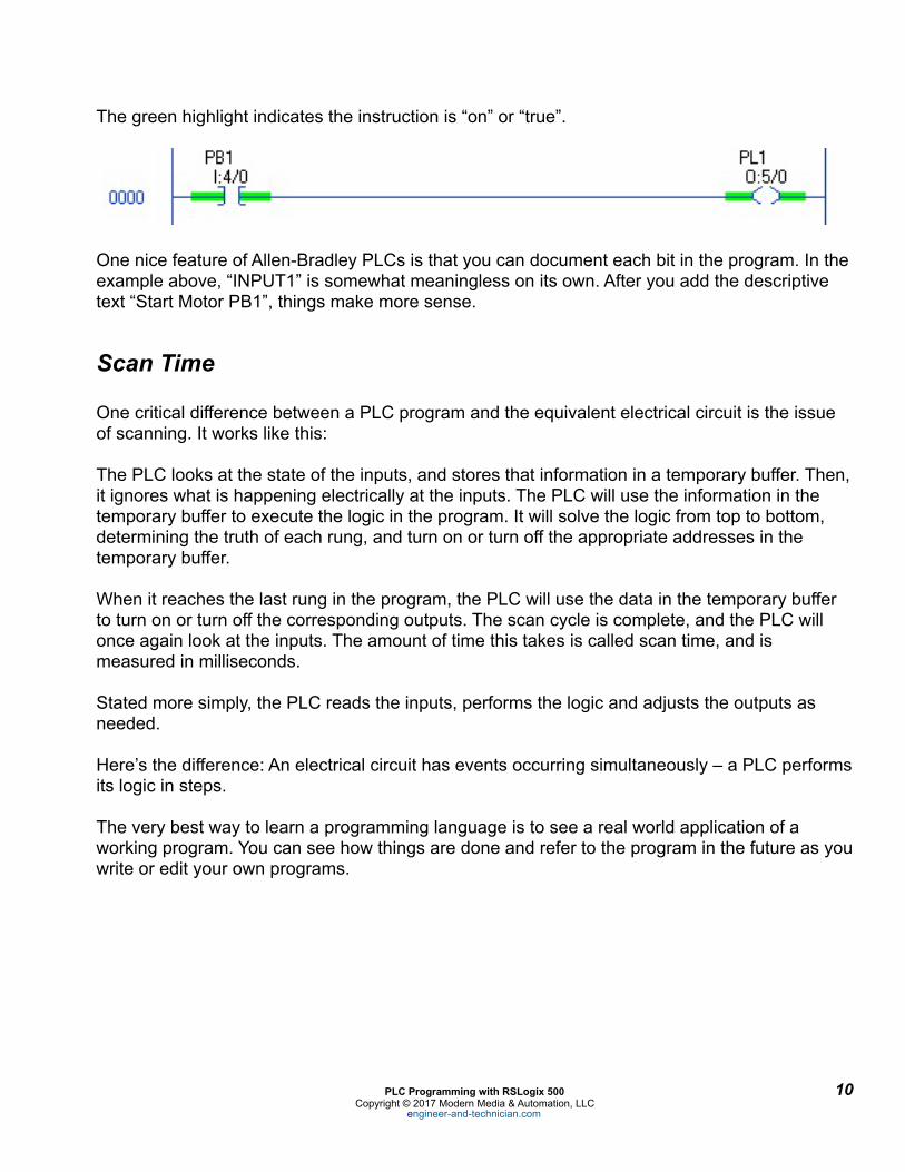
The green highlight indicates the instruction is “on” or “true”.
!
One nice feature of Allen-Bradley PLCs is that you can document each bit in the program. In the example above, “INPUT1” is somewhat meaningless on its own. After you add the descriptive text “Start Motor PB1”, things make more sense.
Scan Time
One critical difference between a PLC program and the equivalent electrical circuit is the issue of scanning. It works like this:
The PLC looks at the state of the inputs, and stores that information in a temporary buffer. Then, it ignores what is happening electrically at the inputs. The PLC will use the information in the temporary buffer to execute the logic in the program. It will solve the logic from top to bottom, determining the truth of each rung, and turn on or turn off the appropriate addresses in the temporary buffer.
When it reaches the last rung in the program, the PLC will use the data in the temporary buffer to turn on or turn off the corresponding outputs. The scan cycle is complete, and the PLC will once again look at the inputs. The amount of time this takes is called scan time, and is measured in milliseconds.
Stated more simply, the PLC reads the inputs, performs the logic and adjusts the outputs as needed.
Here’s the difference: An electrical circuit has events occurring simultaneously – a PLC performs its logic in steps.
The very best way to learn a programming language is to see a real world application of a working program. You can see how things are done and refer to the program in the future as you write or edit your own programs.
PLC Programming with RSLogix 500 ! 10Copyright © 2017 Modern Media & Automation, LLC
engineer-and-technician.com
Project Scope
We will use a batching operation as an example. Batching, as you may know, is the term that describes the mixing of assorted ingredients to make a finished product.
There are techniques that are common to batching, whether you are making soap or cake mix. We are going to write a program that mixes a hypothetical window cleaner.
Someone has to define the batching procedure. Usually, this is done by a process engineer or a chemical engineer. If the job of defining the project is done well, a document called a Project Scope (or something similar) is generated.
It is extremely important that you clearly understand the entire process that is defined in the scope. If you have any questions or concerns, you need to resolve those before you begin programming. If you don’t, then the responsibility of errors and omissions, and perhaps the blame, may be placed on you.
If you bring up questions that result in changes to the defined sequence of operations, ask the originator to revise the Project Scope. In fact, it is not uncommon for a Project Scope to undergo a number of revisions.
If there is a change that is not documented in the scope, you should document it by getting an email from the originator that explains the change. If nothing else, you want to make sure you understand what the change involves.
For our project, the project scope is as follows.
PLC Programming with RSLogix 500 ! 11Copyright © 2017 Modern Media & Automation, LLC
engineer-and-technician.com
!
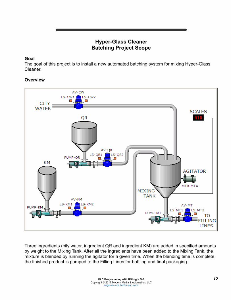
Hyper-Glass Cleaner Batching Project Scope
Goal The goal of this project is to install a new automated batching system for mixing Hyper-Glass Cleaner.
Overview
!
Three ingredients (city water, ingredient QR and ingredient KM) are added in specified amounts by weight to the Mixing Tank. After all the ingredients have been added to the Mixing Tank, the mixture is blended by running the agitator for a given time. When the blending time is complete, the finished product is pumped to the Filling Lines for bottling and final packaging.
PLC Programming with RSLogix 500 ! 12Copyright © 2017 Modern Media & Automation, LLC
engineer-and-technician.com
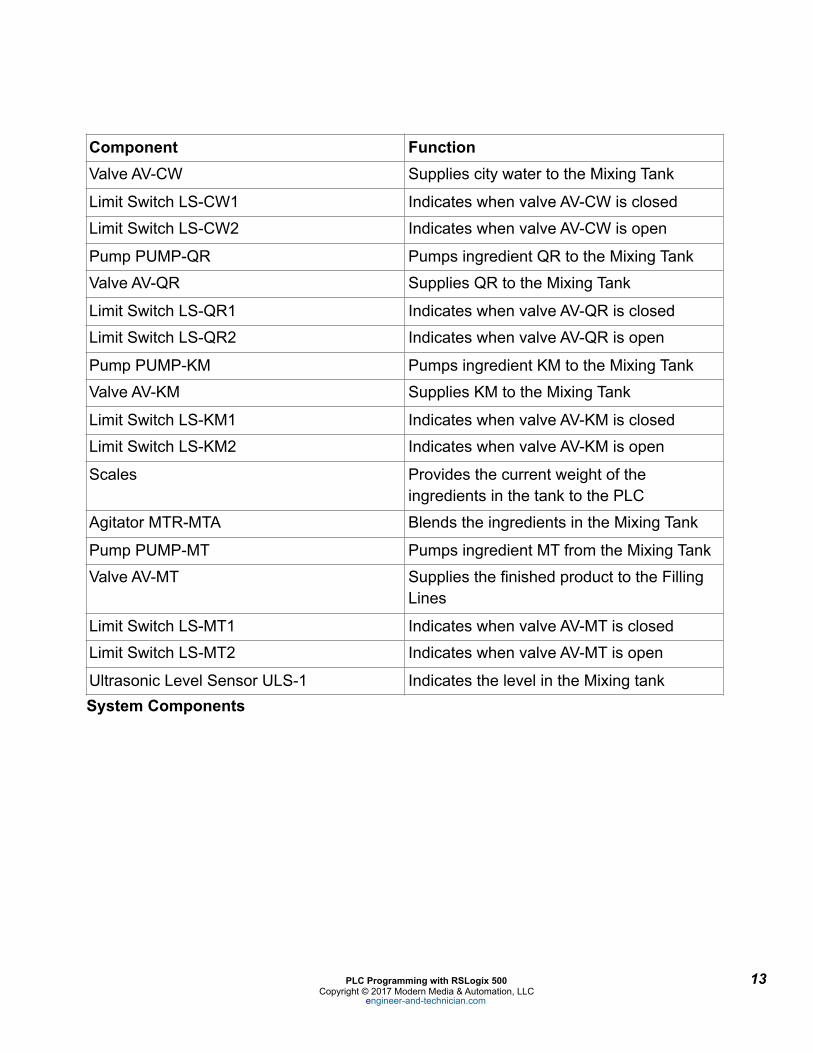
System Components
Component FunctionValve AV-CW Supplies city water to the Mixing Tank
Limit Switch LS-CW1 Indicates when valve AV-CW is closed
Limit Switch LS-CW2 Indicates when valve AV-CW is open
Pump PUMP-QR Pumps ingredient QR to the Mixing Tank
Valve AV-QR Supplies QR to the Mixing Tank
Limit Switch LS-QR1 Indicates when valve AV-QR is closed
Limit Switch LS-QR2 Indicates when valve AV-QR is open
Pump PUMP-KM Pumps ingredient KM to the Mixing Tank
Valve AV-KM Supplies KM to the Mixing Tank
Limit Switch LS-KM1 Indicates when valve AV-KM is closed
Limit Switch LS-KM2 Indicates when valve AV-KM is open
Scales Provides the current weight of the ingredients in the tank to the PLC
Agitator MTR-MTA Blends the ingredients in the Mixing Tank
Pump PUMP-MT Pumps ingredient MT from the Mixing Tank
Valve AV-MT Supplies the finished product to the Filling Lines
Limit Switch LS-MT1 Indicates when valve AV-MT is closed
Limit Switch LS-MT2 Indicates when valve AV-MT is open
Ultrasonic Level Sensor ULS-1 Indicates the level in the Mixing tank
PLC Programming with RSLogix 500 ! 13Copyright © 2017 Modern Media & Automation, LLC
engineer-and-technician.com
The operator will then press the “START BATCH” pushbutton to begin the batching process. The “SYSTEM READY” pilot light will turn off. No further operator input is required.
Step 1 – City Water Automatic valve AV-CW will open. The “ADDING WATER” pilot light will illuminate.
Valve AV-CW will remain open until 1275 lbs. of City Water is in the Mixing Tank. Valve AV-CV will close.
The state of AV-CW will be verified by limit switch LS-CW2. If LS-CW2 is not made within 2 seconds after the valve was told to open, a fault will be generated and the system will shut down. The pilot light “SYSTEM FAULT” PL2 will illuminate indicating that a fault has occurred.
LS-CW1 will verify that the valve is closed within 2 seconds after the valve was told to close. If the valve closure is not verified within 2 seconds, a fault will be generated, the system will shut down and PL2 will illuminate.
All valves and their respective limit switches will work in the manner described above.
After the City Water has been added, valve AV-CW will close and the “ADDING WATER” pilot light will turn off.
Step 2 – Ingredient QR Valve AV-QR will be opened. After the valve position has been verified by LS-QR2, PUMP-QR will pump 390 lbs. of ingredient QR into the Mixing Tank. The “ADDING QR” pilot light will be illuminated while the pump is running.
After the ingredient QR has been added to the Mixing Tank, PUMP-QR stops and the “ADDING QR” pilot light will turn off. Valve AV-QR will close.
Step 3 – Ingredient KM Valve AV-KM will be opened. After the valve position has been verified by LS-KM2, PUMP-KM will pump 173 lbs. of ingredient KM into the mixing tank. The “ADDING KM” pilot light will be illuminated while the pump is running.
After the ingredient KM has been added to the Mixing Tank, valve AV-KM will close. PUMP-KM will stop. The “ADDING KM” pilot light will turn off.
After LS-KM1 indicates the valve has been closed, the agitator motor MTR-MTA will start. The “BLENDING” pilot light will illuminate.
Step 4 – Mixing The agitator will run for 3 minutes. The “BLENDING” pilot light will illuminate.
After the agitator is finished, the “BLENDING” pilot light will turn off.
PLC Programming with RSLogix 500 ! 16Copyright © 2017 Modern Media & Automation, LLC
engineer-and-technician.com

Step 5 – Pump to filling lines Valve AV-MT will open. After LS-MT1 indicates the valve is open, the “PUMPING TO LINES” pilot light will illuminate.
PUMP-MT will pump the entire batch to the filling lines. When the Ultrasonic Level Sensor ULS-1 indicates that the tank is empty, PUMP-MT will turn off, valve AV-MT will close and the batching cycle is complete. The “PUMPING TO LINES” pilot light will turn off and the “SYSTEM READY” pilot light will illuminate.
During every phase of the batching process, the liquid level must be monitored by the PLC. If the level rises to greater than 95% of that Mixing tank’s capacity, the system will generate a fault and the batching process must be halted.
The operator may press the “E-STOP” pushbutton PB3 to stop the process at any time.
END OF HYPER-GLASS CLEANER BATCHING PROJECT SCOPE
Summarizing the Scope
So, what did we get from the scope? Let’s summarize:
First, 1275 lbs. of water will be added to the Mixing Tank. Then, 390 lbs. of QR will be added. The last ingredient is KM, of which we will add 173 lbs.
After all the ingredients are in the Mixing Tank, we have to blend it for 3 minutes.
After the batch is blended, we will pump the finished product in the tank to the filling lines.
We have to make sure all the valves open or close in less than 2 seconds. If they do not, then we need to shut down the process.
We need to turn on the appropriate pilot lights to indicate what stage the batching process is in.
We need to make sure the level in the Mixing Tank doesn’t get too high. If it does, we must shut down everything.
We need to make sure that the respective valves for the pumps are open before we turn on the pumps.
PLC Programming with RSLogix 500 ! 17Copyright © 2017 Modern Media & Automation, LLC
engineer-and-technician.com
Which PLC? There are certainly a number of factors that will determine which PLC you need. Without getting into all of those, let’s just say that an SLC 5/03 has plenty of processing power for this project and the cost is reasonable, so we will use one.
Before you can determine what modules, rack or power supply you need to buy, you will have to know what your I/O requirements are. This involves the very critical step of laying out your I/O.
A bit of advice here: Don’t skimp on this step. Make sure the I/O is right before you begin programming. A mistake or omission here will cost you ten-fold further down the road.
Lay Out The I/O Now we need to layout the I/O. This will tell us the addresses for the I/O points, what PLC modules we need and how the PLC modules need to be wired.
There are three types of signals in the batching system: 120VAC digital inputs (limit switches and pushbutton switches) 120VAC digital outputs (valves, motors and pilot lights) and analog 1
0-10VDC inputs.
List all of the components in the system that are connected to the PLC. Categorize each component according its type (digital input, digital output or analog 0-10VDC). It is best to do this in an Excel spreadsheet. I have provided one for this project – it is called IO_List.xls and is included in the files you downloaded.
Try to keep associated devices together. For example, the “ADDING WATER” pilot light should be near Valve AV-CW. This will make the electrical prints easier to read and also help to keep the PLC program organized.
Technically, the valves themselves are not 120VAC devices, but in this case, the solenoids that subsequently drive 1
the valves are. Likewise, the motors that run the pumps and the agitators may not be 120VAC, but the control circuitry that operates the motors is 120VAC.
PLC Programming with RSLogix 500 ! 18Copyright © 2017 Modern Media & Automation, LLC
engineer-and-technician.com
This is a good time to call your local Allen-Bradley representative and have him assist you in selecting the parts you need. He can work directly from your I/O listing and probably save you a bunch of time.

Notice the “Descriptor” column. This is a statement providing a shorthand description of the device when the associated input is on, or true. We will use these descriptors in the actual PLC program.
Descriptors look like this in RSLogix 500.
!
I can’t stress how important it is to get the verbiage right in a descriptor. For example, let’s look at LS-CW1. This particular limit switch is normally open, but held closed when the valve is closed.
When the limit switch is closed, the input to the PLC will be on, or true.
If we used the descriptor
Limit Switch LS-CW1
that wouldn’t tell us too much without referring to the prints. Plus, it is a little redundant, as we know it is a limit switch based on the “LS” prefix in the device name.
If, however, we use the descriptor
City Water Valve AV-CW
Closed LS-CW1
then that tells us immediately, without referring to the prints, that the City Water valve is closed as indicated by the limit switch LS-CW1.
After you go online with a PLC, if an input is on, the symbol for the bit is highlighted. You can quickly realize the descriptor statement is currently true, as shown below.
!
PLC Programming with RSLogix 500 ! 19Copyright © 2017 Modern Media & Automation, LLC
engineer-and-technician.com
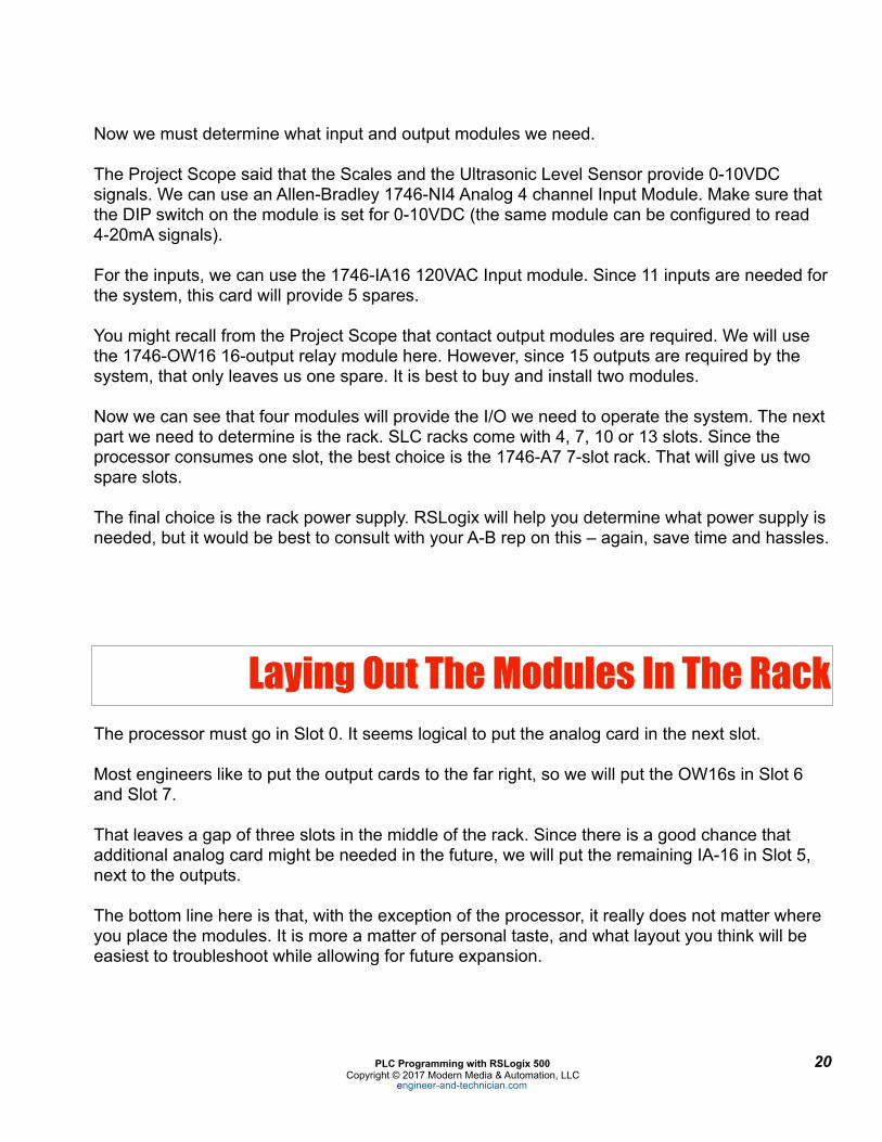
Now we must determine what input and output modules we need.
The Project Scope said that the Scales and the Ultrasonic Level Sensor provide 0-10VDC signals. We can use an Allen-Bradley 1746-NI4 Analog 4 channel Input Module. Make sure that the DIP switch on the module is set for 0-10VDC (the same module can be configured to read 4-20mA signals).
For the inputs, we can use the 1746-IA16 120VAC Input module. Since 11 inputs are needed for the system, this card will provide 5 spares.
You might recall from the Project Scope that contact output modules are required. We will use the 1746-OW16 16-output relay module here. However, since 15 outputs are required by the system, that only leaves us one spare. It is best to buy and install two modules.
Now we can see that four modules will provide the I/O we need to operate the system. The next part we need to determine is the rack. SLC racks come with 4, 7, 10 or 13 slots. Since the processor consumes one slot, the best choice is the 1746-A7 7-slot rack. That will give us two spare slots.
The final choice is the rack power supply. RSLogix will help you determine what power supply is needed, but it would be best to consult with your A-B rep on this – again, save time and hassles.
Laying Out The Modules In The Rack The processor must go in Slot 0. It seems logical to put the analog card in the next slot.
Most engineers like to put the output cards to the far right, so we will put the OW16s in Slot 6 and Slot 7.
That leaves a gap of three slots in the middle of the rack. Since there is a good chance that additional analog card might be needed in the future, we will put the remaining IA-16 in Slot 5, next to the outputs.
The bottom line here is that, with the exception of the processor, it really does not matter where you place the modules. It is more a matter of personal taste, and what layout you think will be easiest to troubleshoot while allowing for future expansion.
PLC Programming with RSLogix 500 ! 20Copyright © 2017 Modern Media & Automation, LLC
engineer-and-technician.com
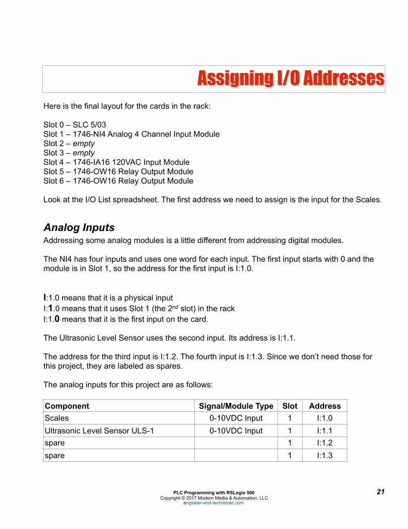
Assigning I/O Addresses Here is the final layout for the cards in the rack:
Slot 0 – SLC 5/03 Slot 1 – 1746-NI4 Analog 4 Channel Input Module Slot 2 – empty Slot 3 – empty Slot 4 – 1746-IA16 120VAC Input Module Slot 5 – 1746-OW16 Relay Output Module Slot 6 – 1746-OW16 Relay Output Module
Look at the I/O List spreadsheet. The first address we need to assign is the input for the Scales.
Analog Inputs Addressing some analog modules is a little different from addressing digital modules.
The NI4 has four inputs and uses one word for each input. The first input starts with 0 and the module is in Slot 1, so the address for the first input is I:1.0.
I:1.0 means that it is a physical input I:1.0 means that it uses Slot 1 (the 2nd slot) in the rack I:1.0 means that it is the first input on the card.
The Ultrasonic Level Sensor uses the second input. Its address is I:1.1.
The address for the third input is I:1.2. The fourth input is I:1.3. Since we don’t need those for this project, they are labeled as spares.
The analog inputs for this project are as follows:
Component Signal/Module Type Slot AddressScales 0-10VDC Input 1 I:1.0Ultrasonic Level Sensor ULS-1 0-10VDC Input 1 I:1.1spare 1 I:1.2spare 1 I:1.3
PLC Programming with RSLogix 500 ! 21Copyright © 2017 Modern Media & Automation, LLC
engineer-and-technician.com

Digital Inputs
Our first digital input starts in Slot 4. Therefore, our first input will be I:4/0.
I:4/0 means that it is a physical input I:4/0 means that it uses Slot 4 in the rack I:4/0 means that it is the first input on the card.
Don’t confuse capital “I” with “1”.
As a side note, RSLogix 500 lets you display the same address in a couple of different ways. You can display the first bit in Slot 4 as:
I:4/0 (known as slot/bit)
or
I:4.0/0 (known as slot word/bit)
This is configurable in RSLogix. We will see how to do that in a few moments.
Most people prefer the slot/bit method of displaying I/O addresses, so that is what we will use.
The digital inputs for this project are as follows:
Component Signal/Module Type Slot AddressSTART BATCH pushbutton switch PB1 120VAC Input 4 I:4/0STOP BATCH pushbutton switch PB2 120VAC Input 4 I:4/1Limit Switch LS-CW1 120VAC Input 4 I:4/2Limit Switch LS-CW2 120VAC Input 4 I:4/3Limit Switch LS-QR1 120VAC Input 4 I:4/4Limit Switch LS-QR2 120VAC Input 4 I:4/5Limit Switch LS-KM1 120VAC Input 4 I:4/6Limit Switch LS-KM2 120VAC Input 4 I:4/7Limit Switch LS-MT1 120VAC Input 4 I:4/8Limit Switch LS-MT2 120VAC Input 4 I:4/9spare 120VAC Input 4 I:4/10spare 120VAC Input 4 I:4/11spare 120VAC Input 4 I:4/12spare 120VAC Input 4 I:4/13spare 120VAC Input 4 I:4/14
PLC Programming with RSLogix 500 ! 22Copyright © 2017 Modern Media & Automation, LLC
engineer-and-technician.com

Scroll down in the window and select “1747-L532C/D 5/03 CPU – 16K Mem. OS302”.
!
PLC Programming with RSLogix 500 ! 27Copyright © 2017 Modern Media & Automation, LLC
engineer-and-technician.com

Click “OK” and this screen will appear.
!
On the left, you see an explorer-type menu. This is called the Project tree. All of these folders and files allow you to configure or view properties of the PLC or data files within the PLC.
PLC Programming with RSLogix 500 ! 28Copyright © 2017 Modern Media & Automation, LLC
engineer-and-technician.com

When you are finished, your configuration should look like this:
!
The “Power Supply” button will help you select the right power supply for the rack based on the modules you have specified, but it is best to contact your Rockwell representative to help you with this.
If you are online for the first time with a PLC, the “Read IO Config” button will tell you how the PLC’s I/O is configured.
The “Adv Config” button allows you to perform advanced configuration functions for each card. In this case with our modules, there is no need to change any of the default values.
When you are done with the I/O configuration, close the window. Your settings will be saved and you will see the main programming screen.
PLC Programming with RSLogix 500 ! 30Copyright © 2017 Modern Media & Automation, LLC
engineer-and-technician.com

Configuring Colors, Fonts and Address Display
This is something that you can certainly configure to your own liking. However, I prefer to change the defaults as follows to make the display easier to read when I am online.
Select
View > Properties > Colors
In the “Set Colors for:” window, click on “Descriptions”. Choose white as a background color.
Select the “Fonts” tab. Depending on your monitor, you may prefer something else, but I like Arial. Select the font size of your choice and click “OK”.
Select the “Address Display” tab.
Choose “Single Line” for “Bit Address Format”.
Choose “Word/Bit” for “Binary Bit Display Mode”.
Choose “Slot/Bit” for “I/O Bit Display Mode”.
Adding Descriptors To Your I/O
A descriptor is the text that is associated with any instruction, such as an XIO, XIC, timer or counter. These are essential when you are writing or trouble-shooting a program.
In RSLogix, find the output file O0 – OUTPUT in the Data Files folder and double-click on it. The screen below will appear.
!
PLC Programming with RSLogix 500 ! 31Copyright © 2017 Modern Media & Automation, LLC
engineer-and-technician.com

Now find the input file I1 – INPUT in the Data Files folder and double-click on it.
!
This looks a little different from the output file. It is because we have an analog input card. Again, scrolling to the right or stretching out the window will reveal what type of card is configured for each slot.
The first line showing address I:1.0 is for the first channel of the Analog NI4 card. In our case, this is where the Scales for the Mixing Tank will be wired. Since it is a word we will be seeing, and not just one bit, we want to add the descriptor to the entire word.
In the “Offset” column, click on “I:1.0”. The whole line will be highlighted. Now double-click on the “Desc:” field and paste the description from the spreadsheet for the Scales. Click “OK”.
Click on “I:1.1” to add the description for the Ultrasonic Level Sensor.
We are not using channels 3 and 4, so we can go to the discrete inputs.
Click on the “0” in the lower right of the table so that I:4/0 shows up in the box. Add the descriptor just like you did for the outputs. Continue until you have all the inputs labeled. Close the window.
You can enter descriptors for Binary (B3) files, Timer (T4) files, Counters (C5) and so in the same way. If you know how these files are going to be laid out then it is a good idea to add descriptors now. In our case, we will add descriptors to these bits and files as we program.
PLC Programming with RSLogix 500 ! 33Copyright © 2017 Modern Media & Automation, LLC
engineer-and-technician.com
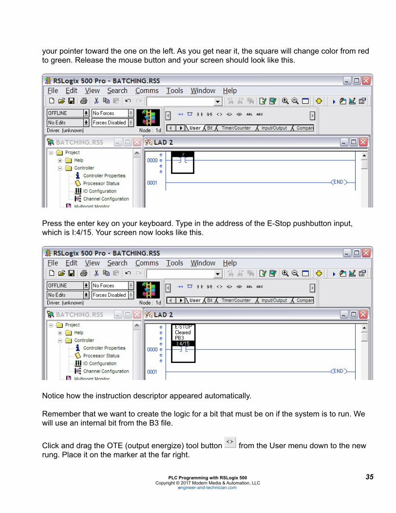
your pointer toward the one on the left. As you get near it, the square will change color from red to green. Release the mouse button and your screen should look like this.
!
Press the enter key on your keyboard. Type in the address of the E-Stop pushbutton input, which is I:4/15. Your screen now looks like this.
!
Notice how the instruction descriptor appeared automatically.
Remember that we want to create the logic for a bit that must be on if the system is to run. We will use an internal bit from the B3 file.
Click and drag the OTE (output energize) tool button ! from the User menu down to the new rung. Place it on the marker at the far right.
PLC Programming with RSLogix 500 ! 35Copyright © 2017 Modern Media & Automation, LLC
engineer-and-technician.com
!
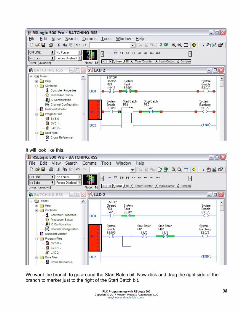
It will look like this.
!
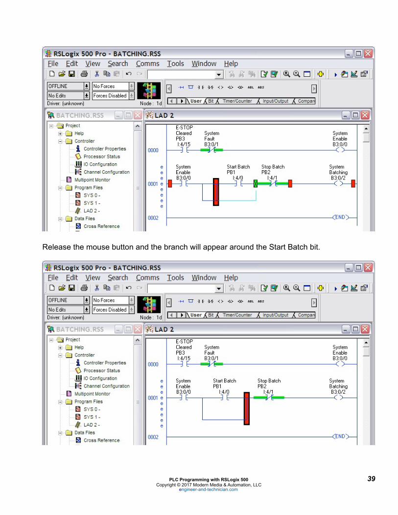
We want the branch to go around the Start Batch bit. Now click and drag the right side of the branch to marker just to the right of the Start Batch bit.
PLC Programming with RSLogix 500 ! 38Copyright © 2017 Modern Media & Automation, LLC
engineer-and-technician.com
!
Release the mouse button and the branch will appear around the Start Batch bit.
!
PLC Programming with RSLogix 500 ! 39Copyright © 2017 Modern Media & Automation, LLC
engineer-and-technician.com