PLC and Data Acquisition Systems
105
SRI CHANDRASEKHARENDRA SARASWATHI VISWA MAHAVIDYALAYA (University U/S 3 of UGC Act 1956) Accredited with “A” Grade by NAAC ENATHUR, KANCHIPURAM - 631561 Course Material SUBJECT : PLC AND DATA ACQUISITION SYSTEMS YEAR/SEM : THIRD/SIXTH DEPARTMENT : EIE/MECHATRONICS Prepared by, K.SARASWATHI, Assistant Professor Department of Electronics and Instrumentation Engineering Sri Chandrasekharendra Saraswathi Viswa Mahavidyalaya Enathur, Kanchipuram - 631561
Transcript of PLC and Data Acquisition Systems

SRI CHANDRASEKHARENDRA SARASWATHI VISWA MAHAVIDYALAYA
(University U/S 3 of UGC Act 1956) Accredited with “A” Grade by NAAC
ENATHUR, KANCHIPURAM - 631561
Course Material
SUBJECT : PLC AND DATA ACQUISITION SYSTEMS
YEAR/SEM : THIRD/SIXTH
DEPARTMENT : EIE/MECHATRONICS
Prepared by,
K.SARASWATHI,
Assistant Professor Department of Electronics and Instrumentation Engineering Sri Chandrasekharendra Saraswathi Viswa Mahavidyalaya
Enathur, Kanchipuram - 631561

PLC and Data Acquisition Systems
Course Material Page 2
PRE-REQUISITE
1. Digital Electronics.
COURSE OBJECTIVES (45hrs)
1. To study the evolution and advantages of PLC.
2. To understand the various PLC instructions.
3. To study the used of PLC for some specific applications
4. To understand the need of computer control in automation.
5. To study the data acquisition systems.
UNIT 1. BASICS OF PLC (9hrs)
Definition and History of PLC-PLC advantage and disadvantages- Over all PLC systems-
CPU and Programmer/Monitors-PLC input and output models – Architecture- PLC
Programming language – Relay logic – Ladder logic – Programming of Gates – Flow charting as
a programming method – connecting PLC to computer - PLC Troubleshooting and Maintenance.
UNIT 2. PLC PROGRAMMING (9hrs)
Programming of Timers – Introduction - ON delay, OFF delay, Retentive Timers – PLC
Timer functions – Examples of timer function Industrial application. Programming Counters –
up/down counter – Combining counter - Examples of counter function Industrial
application.PLC Arithmetic Functions – PLC number Comparison function
UNIT 3. PLC DATA HANDLING FUNCTIONS (9hrs)
PLC Program Control Instructions: Master Control Reset - Skip – Jump and Move
Instruction. Sequencer instructions - Types of PLC Analog modules and systems, PLC analog
signal processing – BCD or multi bit data processing – Case study of Tank level control system,
bottle filling system and Sequential switching of motors
UNIT 4. COMPUTER CONTROL – INTRODUCTION (9hrs)
Need of computer in a control system-Functional block diagram of a computer control
system-Data loggers- Supervisory computer control- Direct digital control-Digital control
interfacing-SCADA.
UNIT 5. DATA ACQUISITION SYSTEMS (9hrs)
Sampling theorem – Sampling and digitizing – Aliasing – Sample and hold circuit –
Practical implementation of sampling and digitizing – Definition, design and need for data
acquisition systems – Interfacing ADC and DAC with Microprocessor / Multiplexer -
Multiplexed channel operation –Microprocessor/PC based acquisition systems.
SEM: VI
PLC AND DATA ACQUISITION SYSTEMS
L T P C
BRANCH: EIE 3 3
CODE: Category: PCC

PLC and Data Acquisition Systems
Course Material Page 3
COURSE OUTCOMES The students should be able to:
CO1. Understand the fundamental of PLC.
CO2. Program a PLC with different logical languages.
CO3. Various industrial applications of PLCs are studied.
CO4. Able to understand the need of computer in Automation.
CO5. Understand the basics of data conversion and data acquisition.
TEXT BOOKS:
[1] Petrezeulla, “Programmable Logic Controllers”, McGraw Hill, 1989.
[2] Curtis D. Johnson,” Process Control Instrumentation Technology”, 8th edition Prentice
Hall June 2005
REFERENCES: [1] Hughes .T, “Programmable Logic Controllers”, ISA Press, 1989.
[2] G.B.Clayton,” Data Converters”, The Mac Millian Press Ltd., 1982.
[3] John w.Webb & Ronald A.Reis., “Programmable logic controllers- principles and
applications”, 5th Edition – PHI Learning Pvt. LTd, New Delhi -2010.

PLC and Data Acquisition Systems
Course Material Page 4
UNIT 1
BASICS OF PLC
AIM:
To understand and the Architecture and types of PLC.
PRE-REQUISITE:
1. Digital Electronics
2. Sensors and Actuators
PRE-MCQ:
1. The acronym PLC stands for: a. Pressure Load Control b. Programmable Logic Controller c. Pneumatic Logic Capstan d. PID Loop Controller
2. Ladder logic programming consists primarily of:
a. Virtual relay contacts and coils b. Logic gate symbols with connecting lines c. Function blocks with connecting lines d. Text-based code
3. From the following which is the advantage of PLC SCADA system.
a. Data can be viewed from any where
b. Possible to connect thousands of sensors
c. Data can be display in any way
d. All of above
4. Which of the following is not the advantage of PLC over relay logic?
a. PLC is solid state devices, hence very compact.
b. They are extremely Rugged
c. They are highly flexible
d. Expensive
5. PLC is capable of handling
a. Analog signals alone
b. Digital signals alone
c. Both Analog and Digital signals
d. None

PLC and Data Acquisition Systems
Course Material Page 5
Programmable Logic Controller
The National Electrical Manufactures Association (NEMA) defines a PLC as a “Digital
operating electronic apparatus which uses a programmable memory for the internal
storage of instruments by implementing specific functions, such as logic, sequencing,
timing, counting, and arithmetic to control through digital or analog I/O modules
various types of machines or processes.”
In simple terms PLC is a solid-state industrial control device which receives signals
from user supplied controlled devices, such as sensors and switches, implements them
in a precise pattern determined by ladder-diagram based application progress stored in
user memory, and provides outputs for control of processes or user supplied devices,
such as relays or motor starters.
PLCs come in different types, and it is generally chosen for an application depending
upon the number of inputs and outputs in a process.
PLC History
PLC development began in 1968 in response to a request from an US car manufacturer (GE). The first PLCs were installed in industry in 1969.
Communications abilities began to appear in approximately 1973. They could also be used in the 70’s to send and receive varying voltages to allow them to enter the analog world.
The 80’s saw an attempt to: standardize communications with manufacturing automation protocol (MAP), reduce the size of the PLC, and making them software programmable through symbolic programming on personal computers instead of dedicated programming terminals or handheld programmers.
The 90’s have seen a gradual reduction in the introduction of new protocols, and the modernization of the physical layers of some of the more popular protocols that survived the 1980’s.
The latest standard “IEC 1131-3” has tried to merge plc programming languages under one international standard. We now have PLCs that are programmable in function block diagrams, instruction lists, C and structured text all at the same time.
Special Features of Programmable Logic Controller
PLCs is designed as a replacement for the hardwired rely and timer logic to be found in
traditional control panels, where PLC provides ease and flexibility of control based on

PLC and Data Acquisition Systems
Course Material Page 6
programming and executing logic instructions. The internal functions such as timers,
counters and shift registers making sophisticated control possible using even the
smallest PLC. PLC requires shorter installation and commissioning times than do hard-
wired system. PLCs are similar to conventional computer in terms of hardware
technology.
Special Features of Programmable Logic Controller:
Reduced space: PLCs are completely solid state devices and hence are extremely
compact in comparison to hard-wired controller where electro-mechanical devices are
used.
Higher Life and Reliability: These devices are extremely rugged. The chances of
defect/damage are very less as there is very lesser moving mechanisms here.
Economical: As the defect probability is very less, One can consider it as one time
investment. In this way, PLCs are undoubtedly most economical systems. Cost of PLC
recovers within a short period.
Energy saving: Average power consumption is just 1/10th of power consumed by an
equivalent relay based control.
Ease of maintenance: i. Modular replacement: Modular Plug-in construction, allowing
easy replacement or addition of units (input/output).
ii. Easy trouble shooting: Ease of programming and reprogramming in-plant.
iii. Error diagnostics with programming unit: Easily understood programming
language.
Tremendous flexibility: There is no requirement of rewiring if any change is required
to be implemented. It can carry out complex functions like arithmetic operations,
counting, comparing, generation of time delay etc. It has a very high processing speed
and greater flexibility in both analog and digital process. “On Line”/ ‘Off Line’
programming is also possible in it.
Shorter Project Time: The hard wired control system can be constructed only when the
task is fully defined. However, In case of PLC , the construction of the controller and
wiring are independent of control program definition.
Easier Storage Archiving and Documentation: This is due to its compatibility with
PC-AT, Printer and Floppy disk.

PLC and Data Acquisition Systems
Course Material Page 7
Communication: Capable of communicating with other PLCs, computers and
intelligent devices.
Advantages and Disadvantages of a PLC
However, if we compare Programmable logic controller function with computers, it has
following advantages and disadvantages:
Advantages:
Many inputs and outputs, excellent for controlling and monitoring many
processes.
Designed for industrial environments, very robust and reliable.
Reprogrammable.
Modular.
Ideally suited to supervisory control.
Disadvantages of a PLC
For simple applications where relay logic might suffice, using a PLC might blow
out costs due to the need to hire a programmer.
Math functions in a PLC are quite advanced, but when it comes to doing large
amounts of complex math computations then an industrial PC might be better
suited.
Certain robotic and positioning applications may require extremely high speed
execution which may not be able to be achieved form a PLC.
Can be expensive for automating an application with fixed parameters for mass
production as compared to a microcontroller.
Types of PLCs
The general classification of PLC based upon the number of input and outputs is :
Fixed types PLC
Modular type PLC
Rack type PLC/ Distributed PLC

PLC and Data Acquisition Systems
Course Material Page 8
Fixed Type PLC
In this type of PLC all the components of the PLC are as a single unit. The number of
I/O supported by the PLC is decided by the manufacture and cannot be changed. This
type of PLC can support a small number of I/Os. Some examples of fixed PLC types by
different manufacturers and the terminology they use is :
Allen Bradley PLC – Micro
Omron PLC – Compact
Siemens PLC – Basic
Delta PLC – Standard
Koyo PLC – Brick
Advantages & Disadvantages of Fixed PLCs
Advantages of Fixed PLCs
Fixed PLCs have some great advantages over other types of PLCs. They have
been specifically design to cater for smaller, low end automation projects.

PLC and Data Acquisition Systems
Course Material Page 9
Small in size so they do not take up very much space in an enclosure.
Quick and easy to mount.
Low in cost so they are an economical solution for basic applications.
Disadvantages of Fixed PLCs
CPU processing power is low and memory is small so complex tasks can be
difficult to realize.
Inflexible because the number of input, output and communication interfaces are
fixed.
Only suitable for basic applications with small number of inputs and outputs.
Modular Type PLC
Modular PLC is divided by compartments into which separate modules can be
plugged. This feature greatly increases the options and the unit’s flexibility. Mixing
the different types of modules according to the desire is possible. In modular type
PLC the number of I/Os can be increased by the addition of modules to the existing
PLC.
Advantages &Disadvantages of Modular PLCs
Advantages of Modular PLCs
They have been specifically design to cater for medium to high end automation
projects.
Modular PLCs have lager memory, higher performance processors, larger
number of input and outputs, increased communication options, are fully
customizable and are easily expanded. This enables the modular PLC to handle
larger scale applications and of higher complexity .

PLC and Data Acquisition Systems
Course Material Page 10
Modular PLCs also have the ability to have remotely mounted input and output
modules (distributed I/O) that are interconnected using a communication link.
This allows for increase number of inputs and outputs, reduced cable
requirements and installation flexibility.
The modular PLC also has maintenance advantages over fixed PLCs. Each
hardware component is separate housed in a module which can be replaced if it
is faulty.
Disadvantages of Modular PLCs
Large in size so they take up more space in an enclosure than a fixed PLC.
The mounting system is more complex than a fixed PLC.
Higher in cost than a fixed PLC so may not be cost effective for smaller
applications.
Rack Type PLC
In Rack type PLC all the components of the PLC are as separated modules and are
assembled to form one unit by mounting the individual components on a rack. This
PLC can support up to thousands of I/Os.
Advantages & Disadvantages of Rack PLCs
Advantages of a Distributed PLC

PLC and Data Acquisition Systems
Course Material Page 11
Plant wide control network with multiple processors and remote I/O drops.
High performance processor.
Large program and data memory.
Able to handle large volumes of I/O.
Can handle large amounts of complex process control tasks.
Ease of maintenance.
Save time and money on installation costs.
Disadvantages of Distributed PLCs
Large in size with bigger installation footprint.
The mounting system is more complex than a fixed PLC.
Higher in cost than other types of PLC so they may not be cost effective for
smaller less complex applications.
Higher level programming skills may be required.
Types of PLC Manufactures
According to the physical size, a PLC is divided into Mini, Micro, and Nano PLC.
Some of the manufacturers of PLCs include:
Allen Bradley
ABB
Siemens
Mitsubishi PLC
Hitachi PLC
Delta PLC
General Electric (GE) PLC
Honeywell PLC
PLC and Data Acquisition Systems
Course Material Page 12
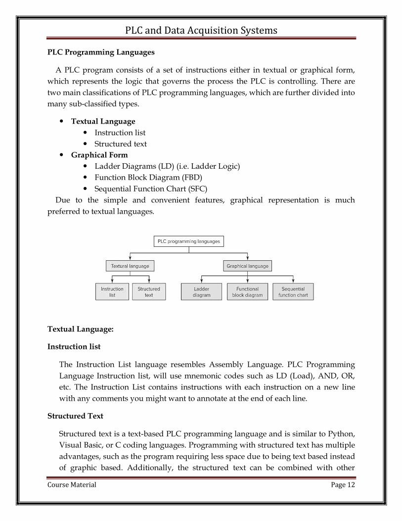
PLC Programming Languages
A PLC program consists of a set of instructions either in textual or graphical form,
which represents the logic that governs the process the PLC is controlling. There are
two main classifications of PLC programming languages, which are further divided into
many sub-classified types.
Textual Language
Instruction list
Structured text
Graphical Form
Ladder Diagrams (LD) (i.e. Ladder Logic)
Function Block Diagram (FBD)
Sequential Function Chart (SFC)
Due to the simple and convenient features, graphical representation is much
preferred to textual languages.
Textual Language:
Instruction list
The Instruction List language resembles Assembly Language. PLC Programming
Language Instruction list, will use mnemonic codes such as LD (Load), AND, OR,
etc. The Instruction List contains instructions with each instruction on a new line
with any comments you might want to annotate at the end of each line.
Structured Text
Structured text is a text-based PLC programming language and is similar to Python,
Visual Basic, or C coding languages. Programming with structured text has multiple
advantages, such as the program requiring less space due to being text based instead
of graphic based. Additionally, the structured text can be combined with other

PLC and Data Acquisition Systems
Course Material Page 13
programming languages, such as creating function blocks containing functions
written in structured text.
Software / Graphical Form Languages:
The PLC manufacturer typically determines PLC development software. Allen
Bradley, Siemens, and GE each have their own software development platforms for
programming their PLC models. Once the platform is determined, the actual
programming of the PLC logic can be done in a few different methods. The most
common methods of PLC programming include Ladder Logic, Function Block, and
structured text.
Ladder Logic
Ladder Logic is a graphical PLC programming language and is the most common
method of programming. Ladder Logic can be used to execute tasks such as
sequencing, counting, timing, data manipulation, and more. Ladder Logic is
structured similarly to relay logic; however, the physical switches and coils used in
relay logic are replaced by the PLC’s memory locations and I/O.
Sequential Function Chart
Sequential Function Chart is similar to Flowchart. Steps act as a major function in
the program. These steps house the actions that occur when the program executed.
This decision can be based on timing, a certain phase of the process, or a physical
state of an equipment. Transitions are the instructions that you use to move from
one step to another step by setting conditions of true or false. Unlike traditional
flowcharts, the Sequential Function Charts can have multiple paths. One can use
branches to initiate multiple steps at one time.
Function Block
Function block PLC programs are represented in the form of graphical blocks.
Signals or data flow into the function block from inputs connected to the PLC. When
the incoming signals or data triggers the function block’s pre-programmed function,
the PLC executes one or more outputs. Function blocks can have standard functions
such as timers, counters, calculating min and max values, obtaining averages, and
more.
PLC TYPE - SOFTWARE USED
Allen Bradley - RSLogixs

PLC and Data Acquisition Systems
Course Material Page 14
Siemens - SIMATIC STEP 7
GE - Versa Pro
Honeywell - Soft Master
PLC Architecture
The components of a PLC are

PLC and Data Acquisition Systems
Course Material Page 15
1. Memory Unit
2. CPU
3. Input/ Output Module
4. Power Supply
Memory unit:
All PLCs contain both RAM and ROM in varying amounts depending upon the
design of the PLC. The use of a PLC's memory is determined again by the design of the
unit. However, all PLC memories can be subdivided into at least five major areas
memory of the PLC .
Executive Memory
System memory
I/O Status Memory
Data Memory
PLC and Data Acquisition Systems
Course Material Page 16
User Program Memory
Executive Memory:
The operating system or executive memory for the PLC is always in ROM since,
once programmed and developed by the manufacturer, it rarely needs changing. It is
the one that actually does the scanning in a PLC. The operating system is a special
machine language program that runs the PLC. It instructs the microprocessor to read
each user instruction, helps the microprocessor to interpret user programmed symbols
and instructions, keeps track of all the I/O status, and is responsible for
maintaining/monitoring the current status of the health of the system and all its
components
System memory:
In order for the operating system to function, a section of the memory is allotted
for system administration. As the executive program performs its duties, it often
requires a place to store intermediate results and information. A section of RAM is
installed for this purpose. Normally this area is allotted for use of the operating system
only and is not available to the user for programming. It might be thought of as a
scratch pad for the operating system to doodle on as necessary. Some PLCs use this area
for storing the information which passes between programmer and operating system,
e.g. the operating system generates certain error codes store in the specific address in
this area during the execution of user program which can be read by user program; or
the user may also give additional information to the operating system before execution
of user program by writing some codes in the specific address in this area, etc.
I/O Status Memory:
I/O Image Table Another portion of RAM is allocated for the storage of current I/O
status. Every single input/output module has been assigned to it a particular location
within the input/output image table. The location within the input and output image
tables are identified by addresses, each location has its own unique address. During the
execution of user program, the microprocessor scans the user program and interpret the
user commands, the status of input modules used are read from the input image table
(not directly from the input module itself). Various output device status generated

PLC and Data Acquisition Systems
Course Material Page 17
during the execution of user program are stored in the output image table (not directly
to output modules). (Find out about input scan and output scan.)
Data Memory:
Whenever timers, counters, mathematics and process parameters are required,
an area of memory must be set aside for data storage. The data storage portion of
memory is allocated for the storage of such items as timers or counter
preset/accumulated values, mathematics instruction data and results, and other
miscellaneous data and information which will be used by any data manipulation
functions in the user program. Some manufacturers subdivide the data memory area
into two sub-memories, one for fixed data and other for variable data. The fixed data
portion can only be programmed via the programming device. The CPU is not
permitted to place data values in this area. The variable portion of the data memory is
available to the CPU for data storage.
User Program Memory:
The final area of memory in a PLC is allocated to the storage of the user program.
It is this memory area that the executive program instructs the microprocessor to
examine or 'scan' to find the user instructions. The user program area may be
subdivided if the CPU allocates a portion of this memory area for the storage of ASCII
messages, subroutine programs, or other special programming functions or routines. In
the majority PLCs, the internal data storage and user program areas are located in
RAM. Several systems do offer an option that places both the user program and the
fixed data storage areas in EPROM type memory. The user can develop program in
RAM and run the system to ensure correct operation. Once the user is satisfied that the
programming is correct, a set of EPROMs is then duplicated from the RAM. Then the
user can shut down the CPU and replaces the RAM with the newly programmed
EPROM. Any future change would require that the EPROMs be reprogrammed.
PLC - CPU unit
The CPU controls and supervises all operations within the PLC, carrying out
programmed instructions stored in the memory. An internal communications highway,
or bus system, carries information to and from the CPU, memory and I/O units, under
control of the CPU. Virtually all modern PLCs are microprocessor-based, using a 'micro'
as the system CPU. Some larger PLCs also employ additional microprocessors to
control complex, time consuming functions such as mathematical processing, three-
term PID control, etc.

PLC and Data Acquisition Systems
Course Material Page 18
I/O Module
Input/output Module Units
The input/output unit of PLCs handles the job of interfacing high power
industrial devices to the low-power electronic circuitry that stores and executes the
control program. Most PLCs operate internally at between 5 and 15V d.c. (common TTL
and CMOS voltages), whilst signal from input devices can be much greater, typically
24V d.c. to 240V a.c. at several amperes. The I/O module units form the interface
between the microelectronics of the programmable controller and the real world
outside, and must therefore provide all necessary signal conditioning and isolation
functions. This often allows a PLC to be directly connected to process actuators and
input devices without the need for intermediate circuitry or relays. To provide this
signal conversion, programmable controllers are available with a choice of
input/output units to suit different requirements.
It is standard practice for all I/O channels to be electrically isolated from the controlled
process, using opto-isolator circuits on the I/O modules. An opto-isolator allows small
signal to pass through, but will clamp any high-voltage spikes or surges down to the
same small level. This provides protection against switching transients and power-
supply surges, normally up to 1500 V. In small self-contained PLCs in which all I/O
points are physically located on one casing, all inputs will be of one type (e.g. 24V) and
the same for outputs (e.g. 240V triac). This is because manufacturers supply only
standard function boards for economic reasons. On the other hand, modular PLCs have

PLC and Data Acquisition Systems
Course Material Page 19
greater flexibility of I/O, since the user can select from several different types and
combinations of input and output modules.
In all cases the input/output module units are designed with the aim of simplifying the
connection of input devices and actuators to the PLC. For this purpose, all PLCs are
equipped with standard screw terminals or plugs on every I/O point, allowing the
rapid and simple removal and replacement of a faulty I/O card. Every input/output
module point has a unique address or channel number which is used during program
development to specify the monitoring of an input or the activating of a particular
output within the program. Indication of the status of input/output channels is
provided by light-emitting diodes (LEDs) on the PLC or I/O unit, making it simple to
check the operation of processed inputs and outputs from the PLC itself
Scan Cycle
Internal Operation and Signal Processing The CPU of the PLC executes the user-
program over and over again when it is in the RUN mode. The following figure shows
the entire repetitive series of events.
(a) Input scan: During the input scan, the current status of every input module is stored
in the input image (memory) table, bringing it up-to-date. Thus all the status of the

PLC and Data Acquisition Systems
Course Material Page 20
input devices (which in turn is connected to the input module) are updated in the input
memory table.
(b) Program scan: Following the input scan, the CPU enters its user program execution,
or program scan. The execution involves starting at the program's first instruction, then
moving on to the second instruction and carrying out its execution sequence. This
continues to the last program instruction. Throughout the user-program execution, the
CPU continually keeps its output image (memory) table up-to-date.
(c) Output scan: During program scan, the output modules themselves are not kept
continually up to date. Instead, the entire output image table is transferred to the output
modules during the output scan which comes after the program execution. Thus the
output devices are activated accordingly during the output scan.
Note that by virtue of the cyclic nature of the program I/O scan, the status of the inputs
and outputs cannot be changed within the same scan cycle. If an input signal changes
state after the input scan, it will not be recognized until the next input scan occurs. The
time to update all inputs and outputs depends on the total number to be copied, but is
typically a few milliseconds in length. The total program execution time (or cycle time)
depends on the length of the control program. Each instruction takes 1-10 µs to execute
depending on the particular programmable controller employed. So a 1K (1024)
instruction program typically has a cycle time of 1-10 ms. However, programmable
controller programs are often much shorter than 1000 instructions, namely 500 steps or
less.
Ladder Logic
Ladder logic uses symbolic expressions and a graphical editor for writing and reading
ladder diagrams making it easier.
How to Draw Ladder Logic Diagrams
The simple way to describe a ladder diagram is a graphic programming
language that uses a series of rails and rungs containing logic symbols that are
combined to form decision making expressions. Ladder diagrams actually look
like a ladder and are more commonly known as ladder logic programming.
The rails in a ladder diagram represent the supply wires of a relay logic control
circuit. There is a positive voltage supply rail on the left hand side and a zero
voltage rail on the right hand side. In a ladder diagram the logic flow is from the
left hand rail to the right hand rail.

PLC and Data Acquisition Systems
Course Material Page 21
The rungs in a ladder diagram represent the wires that connect the components
of a relay control circuit. In a ladder diagram symbols are used to represent the
relay components. The symbols are placed in the rung to form a network of logic
expressions.
When implementing a ladder logic program in a PLC there are seven basic parts
of a ladder diagram that critical to know. They are rails, rungs, inputs, outputs,
logic expressions, address notation/tag names and comments. Some of these
elements are essential and others are optional.
Basic parts of a ladder diagram are detailed below:
Rails – There are two rails in a ladder diagram which are drawn as vertical lines
running down the far most ends of the page. If they were in a relay logic circuit
they would represent the active and zero volt connections of the power supply
where the power flow goes from the left hand side to the right hand side.
Rungs – The rungs are drawn as horizontal lines and connect the rails to the
logic expressions. If they were in a relay logic circuit they would represent the
wires that connect the power supply to the switching and relay components.

PLC and Data Acquisition Systems
Course Material Page 22
Inputs – The inputs are external control actions such as a push button being
pressed or a limit switch being triggered. The inputs are actually hardwired to
the PLC terminals and represented in the ladder diagram by a normally open
(NO) or normally closed (NC) contact symbol.
Outputs – The outputs are external devices that being are turned on and off such
as an electric motor or a solenoid valve. The outputs are also hardwired to the
PLC terminals and are represented in the ladder diagram by a relay coil symbol.
Logic Expressions – The logic expressions are used in combination with the
inputs and outputs to formulate the desired control operations.
Address Notation & Tag Names – The address notation describes the input,
output and logic expression memory addressing structure of the PLC. The tag
names are the descriptions allocated to the addresses.
Comments – Last but by not least, the comments are an extremely important part
of a ladder diagram. Comments are displayed at the start of each rung and are
used to describe the logical expressions and control operations that the rung, or
groups of rungs, are executing. Understanding ladder diagrams is made a lot
easier by using comments.

PLC and Data Acquisition Systems
Course Material Page 23
Addressing in PLC
Connecting PLC with PC:
PLC controller is linked with a PC computer through an RS-232 cable. One end of the
cable is connected to a serial PC port (9-pin or 25-pin connector), while the other end is
connected to an RS-232C connector on RS232 module of a CPM1A controller. In order to
establish a connection with a PC, DIP switch on the connector must be set in "Host"
position.
PLC and Data Acquisition Systems
Course Material Page 24
TROUBLESHOOTING & MAINTENANCE
Troubleshooting Ground Loops
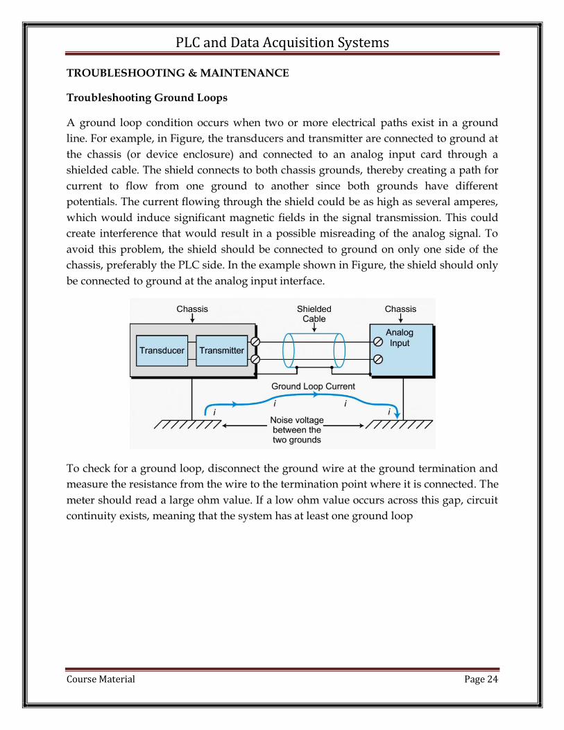
A ground loop condition occurs when two or more electrical paths exist in a ground
line. For example, in Figure, the transducers and transmitter are connected to ground at
the chassis (or device enclosure) and connected to an analog input card through a
shielded cable. The shield connects to both chassis grounds, thereby creating a path for
current to flow from one ground to another since both grounds have different
potentials. The current flowing through the shield could be as high as several amperes,
which would induce significant magnetic fields in the signal transmission. This could
create interference that would result in a possible misreading of the analog signal. To
avoid this problem, the shield should be connected to ground on only one side of the
chassis, preferably the PLC side. In the example shown in Figure, the shield should only
be connected to ground at the analog input interface.
To check for a ground loop, disconnect the ground wire at the ground termination and
measure the resistance from the wire to the termination point where it is connected. The
meter should read a large ohm value. If a low ohm value occurs across this gap, circuit
continuity exists, meaning that the system has at least one ground loop

PLC and Data Acquisition Systems
Course Material Page 25
Troubleshooting Indicator
LED status indicators can provide much information about field devices, wiring, and
I/O modules. Most input/output modules have at least a single indicator—input
modules normally have a power indicator, while output modules normally have a logic
indicator. LED indicators greatly assist the troubleshooting process. With power and
logic indicators, the user can immediately pinpoint a malfunctioning module or circuit.
LED indicators, however, cannot diagnose all possible problems; instead, they serve as
preliminary signs of system malfunctions.
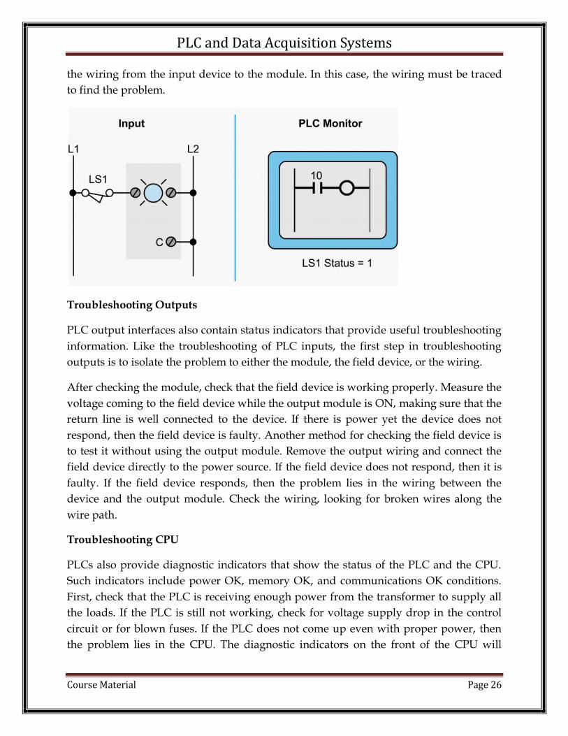
Troubleshooting Inputs
If the field device connected to an input module does not seem to turn ON, a problem
may exist somewhere between the L1 connection and the terminal connection to the
module. An input module’s status indicators can provide information about the field
device, the module, and the field device’s wiring to the module that will help pinpoint
the problem. To further pinpoint the problem, check that voltage is present at the field
device. With the device activated, measure the voltage across the device using a
voltmeter. If no voltage is present on the load side of the device (the side that connects
to the module), then the input device is faulty. If there is power, then the problem lies in
PLC and Data Acquisition Systems
Course Material Page 26
the wiring from the input device to the module. In this case, the wiring must be traced
to find the problem.
Troubleshooting Outputs
PLC output interfaces also contain status indicators that provide useful troubleshooting
information. Like the troubleshooting of PLC inputs, the first step in troubleshooting
outputs is to isolate the problem to either the module, the field device, or the wiring.
After checking the module, check that the field device is working properly. Measure the
voltage coming to the field device while the output module is ON, making sure that the
return line is well connected to the device. If there is power yet the device does not
respond, then the field device is faulty. Another method for checking the field device is
to test it without using the output module. Remove the output wiring and connect the
field device directly to the power source. If the field device does not respond, then it is
faulty. If the field device responds, then the problem lies in the wiring between the
device and the output module. Check the wiring, looking for broken wires along the
wire path.
Troubleshooting CPU
PLCs also provide diagnostic indicators that show the status of the PLC and the CPU.
Such indicators include power OK, memory OK, and communications OK conditions.
First, check that the PLC is receiving enough power from the transformer to supply all
the loads. If the PLC is still not working, check for voltage supply drop in the control
circuit or for blown fuses. If the PLC does not come up even with proper power, then
the problem lies in the CPU. The diagnostic indicators on the front of the CPU will

PLC and Data Acquisition Systems
Course Material Page 27
show a fault in either memory or communications. If one of these indicators is lit, the
CPU may need to be replaced.
The best method for diagnosing input/output malfunctions is to isolate the problem to
the module, the field device, or the wiring. If both power and logic indicators are
available, then module failures become readily apparent. The first step in solving the
problem is to take a voltage measurement to determine if the proper voltage level is
present at the input or output terminal. If the voltage is adequate at the terminal and the
module is not responding, then the module should be replaced. If the replacement
module has no effect, then field wiring may be the problem. A proper voltage level at
the output terminal while the output device is OFF also indicates an error in the field
wiring. If an output rung is activated but the LED indicator is OFF, then the module is
faulty. If a malfunction cannot be traced to the I/O module, then the module connectors
should be inspected for poor contact or misalignment. Finally, check for broken wires
under connector terminals and cold solder joints on module terminals.
POST-MCQ:
1. In a PLC, the scan time refers to the amount of time in which a. the technician enters the program b. timers and counters are indexed by c. one “rung” of ladder logic takes to complete d. the entire program takes to execute
2. The Boolean representation of this PLC program is:
a. ABC + D
b. C + (A + B)D
c. C + D(A + B)
d. C(AB’ + D’)
3. In PLC programming, a retentive function is one that: a. Defaults to the “on” state b. Comes last in the program c. Defaults to the “off” state
d. Is not reset after a power cycle

PLC and Data Acquisition Systems
Course Material Page 28
4. The most popular language for PLCs is:
a. Ladder diagram b. C++ c. OOP+ d. VHDL
5. Normally open contacts are open when:
a. When Input is not energized b. When the input is energized c. When input is higher than 20 volts d. None of these
6. PLCs that have a fixed amount of I/O capability built into the unit are known as:
a. Rack PLCs b. Monolithic PLCs c. Modular PLCs d. None of these
7. Colored contact in PLC ladder diagram indicates:
a. Closed contact b. Open contact c. Any of these d. None of these
8. PLC can be ___________ in plant to change the sequence of operation.
a. only programmed
b. only reprogrammed c. programmed and reprogrammed d. able to give a set point
9. Which of the following cannot be an input that is given to the PLC? a. Manual switches b. Relays c. Sensors d. None of the above
10. The PLC is used in _______.
a. machine tools b. automated assembly equipment c. molding and extrusion machines d. all of the above

PLC and Data Acquisition Systems
Course Material Page 29
Reference:
1. Frank D Petruzella, “Programmable Logic Controllers”, Third Ed 2005, Tata
McGraw Hill Education Private Limited.
2. Rockwell Automation, “Allen Bradley SLC 500 Instruction Set”, Reference
Manual.

PLC and Data Acquisition Systems
Course Material Page 30
UNIT 2
PLC PROGRAMMING
AIM:
To understand the way in which the Timer instruction works in RSLogixs and to study
the various types of Timer instructions and its programming method for industrial
applications.
PRE-REQUISITES:
Basic programming knowledge in RSLogixs 500 with instructions like Examine if open,
Examine if close, Coil, Latch and Unlatch coils.
PRE - MCQ:
1. Which of the following is bit level addressing?
a. I:0/0
b. O:1
c. I:0.0
d. O:1.1
2. If two “Examine if close instructions” are placed parallel to each others, then the
output is?
a. OR
b. EX-OR
c. NOR
d. AND
3. The element used to count the number of times an event happened is?
a. Counter
b. Timer
c. Logic Gates
d. Coil
4. The element used to give delay to turn on and off an output is called?
a. Counter
b. Timer
c. Logic Gates
d. Coil
5. At the maximum how many nested branches can a ladder diagram have?
a. Four

PLC and Data Acquisition Systems
Course Material Page 31
b. Six
c. Five
d. Three
PROGRAMMING TIMERS
INTRODUCTION:
Timers are output instructions used to control operations/events based on time. There
are basically three types of timer instructions in RSLogixs. The three timer instructions
in RSLogixs are:
1. TON - Timer On-Delay
2. TOF - Timer Off-Delay
3. RTO - Retentive Timer On-Delay
The general terms used in Timer instruction.
There are certain parameters which are commonly used in all the three types of timer
instruction to describe its operation. The parameters used to describe the operation of
timer instruction are
1. Preset Value
2. Accumulator Value
3. Time base Value
Preset Value (PRE):
The programmers have to enter the Preset value. Preset value is the set point or
delay time provided by the timer to active or deactivates an event. When the

PLC and Data Acquisition Systems
Course Material Page 32
accumulator value becomes equal to or greater than the preset value, the done (DN) bit
is set. The timer Preset value can range from 0 to 32,767.
Accumulated Value (ACC)
This is the time elapsed since the timer was enabled. For a timer, this is the number of timebase intervals the instruction has counted. Once the timer is reset the accumulator value will reset automatically (not for RTO). Preset and accumulator values for timers range from 0 to +32,767. If a timer preset or accumulator value is a negative value, a runtime error occurs.
Timebase
The timebase determines the duration of each timebase interval. The time base (which is
always expressed in seconds) may be either 1.0 s or 0.01 s. The total value the preset address can hold is 32,767, but if the timebase is 0.01 seconds, this limits the preset time to 0.01 x 32767 = 327 seconds.
Timer data file Elements:
Each timer has three control words (16 bits each) and three control bits (Status bits).
Table 1 Timer Data File
15 14 13 12 11 10 9 8 7 6 5 4 3 2 1 0
Word 0
EN TT DN Internal Use
Word 1
Preset Value
Word 2
Accumulator Value
Addressing:
Enter a TIMER address, TIME BASE, PRESET value, and ACCUM (accumulated) value.
Timer files use three words per element, one for instruction bits (the control word), one for the preset, and one for the accumulator.
T4:1 represents timer file number 4, element number 1. There may be up to 1000 timers in each timer file, numbered from 0 to 999. The timer address must be unique for this timer and may not be used for any other timer.
PLC and Data Acquisition Systems
Course Material Page 33
Timing could be inaccurate if JMP, LBL, JSR, or SBR instructions skip over the rung containing a timer instruction while the timer is timing.
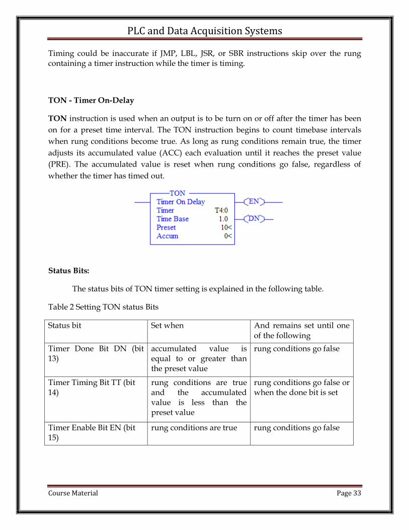
TON - Timer On-Delay
TON instruction is used when an output is to be turn on or off after the timer has been
on for a preset time interval. The TON instruction begins to count timebase intervals
when rung conditions become true. As long as rung conditions remain true, the timer
adjusts its accumulated value (ACC) each evaluation until it reaches the preset value
(PRE). The accumulated value is reset when rung conditions go false, regardless of
whether the timer has timed out.
Status Bits:
The status bits of TON timer setting is explained in the following table.
Table 2 Setting TON status Bits
Status bit Set when And remains set until one of the following
Timer Done Bit DN (bit 13)
accumulated value is equal to or greater than the preset value
rung conditions go false
Timer Timing Bit TT (bit 14)
rung conditions are true and the accumulated value is less than the preset value
rung conditions go false or when the done bit is set
Timer Enable Bit EN (bit 15)
rung conditions are true rung conditions go false

PLC and Data Acquisition Systems
Course Material Page 34
TOF - Timer Off-Delay
Use the TOF instruction to turn an output on or off after its rung has been off for a
preset time interval. The TOF instruction begins to count timebase intervals when the
rung makes a true-to-false transition. As long as rung conditions remain false, the timer
increments its accumulated value (ACC) based on the timebase for each scan until it
reaches the preset value (PRE). The accumulated value is reset when rung conditions go
true regardless of whether the timer has timed out.
Status Bits:
The status bits of TOF timer setting is explained in the following table.
Table 2 Setting TOF status Bits
Status bit Set when And remains set until one
of the following
Timer Done Bit DN (bit 13)
rung conditions are true rung conditions go false and the accumulated value is greater than or equal to the preset value
Timer Timing Bit TT (bit 14)
rung conditions are false and the accumulated value is less than the preset value
rung conditions go true or when the done bit is reset
Timer Enable Bit EN (bit 15)
rung conditions are true rung conditions go false

PLC and Data Acquisition Systems
Course Material Page 35
RTO - Retentive Timer On-Delay
An RTO function the same as a TON with the exception that once it has begun timing, it holds its count of time even if the rung goes false. When rung continuity returns (rung goes true again), the RTO begins timing from the accumulated time which was held when rung continuity was lost. By retaining its accumulated value, retentive timers measure the cumulative period during which rung conditions are true.
The RTO instruction retains its accumulated value when any of the following occurs.
• Rung conditions become false. • You change processor operation from the REM Run or REM Test mode to the REM
Program mode • The processor loses power (provided that battery backup is maintained) • A fault occurs.
Status Bits:
The status bits of RTO timer setting is explained in the following table.
Table 2 Setting RTO status Bits
Status bit Set when And remains set until one of the following
Timer Done Bit DN (bit 13) accumulated value is equal to or greater than the preset value
the appropriate RES instruction is enabled
Timer Timing Bit TT (bit 14)
rung conditions are true and the accumulated value is less than the preset value
Rung conditions go false or when the done bit is set
Timer Enable Bit EN (bit 15)
rung conditions are true rung conditions go false or if the timer is reset with the RES instruction
PLC and Data Acquisition Systems
Course Material Page 36
RTO Reset:
To reset the retentive timer’s accumulated value and status bits after the RTO rung goes
false, you must program a reset (RES) instruction with the same address in another
rung. When the RES instruction having the same address as the RTO is enabled, the
accumulated value and the control bits are reset.
Cascading Timers:
The Programming of two or more timers together is called cascading of timers. Timers
can be interconnected or cascade, to satisfy any required logic. At times there may
require a time-delay period longer than the preset time value allowed for the single
timer instruction of the PLC being used. This can be solved by cascading timers.
Counters
Introduction:
The counters are instructions which are used to count the number of external events. There are two types of Counter Instructions
1. Up Counter CTU
2. Down Counter CTD
The general terms used in Counter instruction.
There are certain parameters which are commonly used in all the two types of Counter
instruction to describe its operation. The parameters used to describe the operation of
timer instruction are
1. Preset Value
2. Accumulator Value
PLC and Data Acquisition Systems
Course Material Page 37
Preset Value (PRE):
The programmers have to enter the Preset value. The Preset value is the set point that you enter in the timer or counter instruction. When the accumulated value becomes equal to or greater than the Preset value, the done status bit is set. You can use this bit to control an output device.
Accumulated Value (ACC)
For a counter, this is the number of false-to-true transitions that have occurred.
Counter data file Elements:
Each counter has three control words (16 bits each) and three control bits (Status bits).
Table 1 Counter Data File
15 14 13 12 11 10 9 8 7 6 5 4 3 2 1 0
Word 0
CU CD DN OV UN - - - - Not Used
Word 1
Preset Value
Word 2
Accumulator Value
Word 0
CU : Count up enables (Bit 15) CD : Count down enables (Bit 14) DN : Done bit (Bit 13) OV : Overflow bit (Bit 12) UN : Underflow bit (Bit 11)

PLC and Data Acquisition Systems
Course Material Page 38
Addressing:
Enter a COUNTER address, PRESET value and ACCUM value. The Preset value is the
point which must be reached to set the DN (done) bit. The accumulated value represents the current count status.
C5:1 represents counter files number 5, element number 1.
Up Counter CTU
This output instruction counts up for each false-to-true transition of conditions preceding it in the rung and produces an output when the accumulated value reaches the Preset value. Rung transitions might be triggered by a limit switch or by parts travelling past a detector.
The ability of the counter to detect false-to-true transitions depends on the speed (frequency) of the incoming signal. The on and off duration of an incoming signal must not be faster than the scan time. Each count is retained when the rung conditions again become false, permitting counting to continue beyond the Preset value. This way you can base an output on the preset but continue counting to keep track of inventory/parts, etc.
The Count value must remain in the range of – 32768 to + 32767. If the count value goes
above + 32767 or below – 32768, the counter status overflow (OV) or underflow (UN) bit
is set. A Counter can be reset to zero using the reset (RES) instruction.
Use a RES (reset) instruction with the same address as the counter, or another instruction in your program to overwrite the value. The on or off status of counter done, overflow, and underflow bits is retentive. The accumulated value and control bits are reset when a RES is enabled. Counter files use three words per element.
Instruction Bits: 12 = OV (count up overflow) bit
13 = DN (done) bit
15 = CU (count up enable) bit.

PLC and Data Acquisition Systems
Course Material Page 39
Setting CTU status Bits:
Status Bit Set When And remains Set until one of the following
Count Up Overflow Bit OV (Bit 12)
accumulated value wraps around to -32,768 (from +32,767) and continues counting up from there
a RES instruction having the same address as the CTU instruction is executed OR the count is decremented less than or
equal to +32,767 with a CTD instruction
Done Bit DN (Bit 13) accumulated value is equal to or greater than the preset value
the accumulated value becomes less than the preset value
Count Up Enable Bit CU (Bit 15)
rung conditions are true rung conditions go false the CTU instruction is enabled
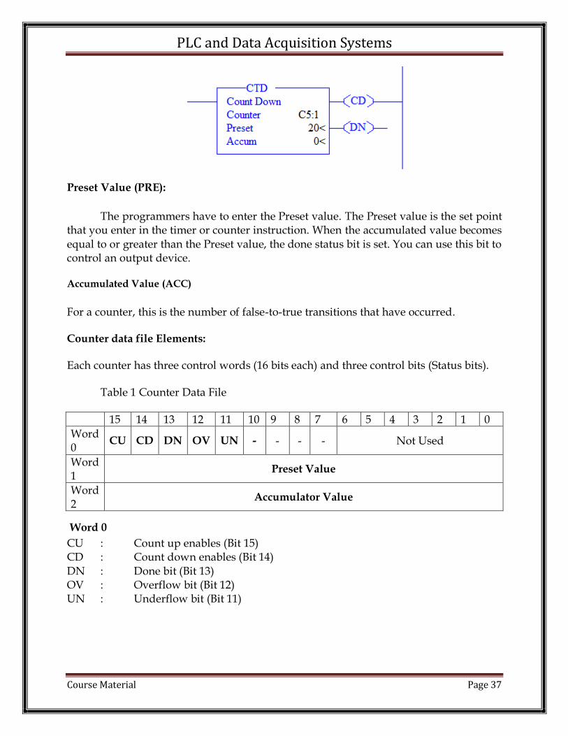
Down Counter CTD:
This output instruction counts down for each false-to-true transition of conditions preceding it in the rung and produces an output when the accumulated value reaches the Preset value. Rung transitions might be triggered by a limit switch or by parts travelling past a detector.
Each count is retained when the rung conditions again become false. The count is retained until a RES (reset) instruction with the same address as the counter is enabled, or if another instruction in your program overwrites the value.
The accumulated value is retained after the CTU or CTD instruction goes false, and when power is removed from and then restored to the processor. Also, the on or off status of counter done, overflow, and underflow bits is retentive. The accumulated

PLC and Data Acquisition Systems
Course Material Page 40
value and control bits are reset when a RES is enabled. Counter files use three words per element.
Instruction Bits: 11 = UN (count down underflow) bit
13 = DN (done) bit
14 = CD (count down enable) bit.
Setting CTD Status Bits:
Status Bit Set When And remains Set until one of the following
Count Down Underflow Bit UN (Bit 11)
accumulated value wraps around to +32,767 (from -32,768) and continues counting down from there
a RES instruction having the same address as the CTD instruction is enabled. OR the count is incremented greater than or equal to +32,767 with a CTU instruction
Done Bit DN (Bit 13) accumulated value is equal to or greater than the Preset value
the accumulated value becomes less than the Preset value
Count Down Enable Bit CD (Bit 14)
rung conditions are true rung conditions go false the CTU instruction is enabled

PLC and Data Acquisition Systems
Course Material Page 41
PLC MATH INSTRUCTION (Arithmetic)
The major of the Math instructions take two input values, perform the specified
arithmetic function, and output the result to an assigned memory location. For example,
both the ADD and SUB instructions take a pair of input values, add or subtract them,
and place the result in the specified destination. If the result of the operation exceeds
the allowable value, an overflow or underflow bit is set.
PLC MATH INSTRUCTION
S.NO Instruction Mnemonic
Instruction Name
Purpose
1. ADD Add Adds source A to source B and stores the result in the destination.
2. SUB Subtraction Subtracts source B from source A and stores the result in the destination.
3. MUL Multiply Multiplies source A by source B and stores the result in the destination.
4. DIV Divide Divides source A by source B and stores the result in the destination and the math register.
5. CLR Clear Sets all bits of a word to zero.
6. SQR Square Root Calculates the square root of the source and places the integer result in the destination.
7. ABS Absolute Calculates the absolute value of the source and places the result in the Destination.
Entering Parameters
• Source is the address (es) of the value(s) on which the mathematical, logical, or
move operation is to be performed. This can be word addresses or program
constants. An instruction that has two source operands does not accept program
constants in both operands.
• Destination is the address of the result of the operation. Signed integers are stored
in two’s complement form and apply to both source and destination parameters.
Using Indexed Word Addresses
You have the option of using indexed word addresses for instruction parameters
specifying word addresses. Using Indirect Word Addresses

PLC and Data Acquisition Systems
Course Material Page 42
Have the option of using indirect word-level and bit-level addresses for instructions
specifying word addresses.
Updates to Arithmetic Status Bits
The arithmetic status bits are found in Word 0, bits 0 to 3 in the controller status file.
After an instruction is executed, the arithmetic status bits in the status file are updated.
Overflow Trap Bit, S:5/0
Minor error bit (S:5/0) is set upon detection of a mathematical overflow or division by
zero. If this bit is set upon execution of an END statement, a Temporary End (TND)
instruction, or an I/O Refresh (REF), the recoverable major error code 0020 is declared.
In applications where a math overflow or divide by zero occurs, you can avoid a CPU
fault by using an unlatch (OTU) instruction with address S:5/0 in your program. The
rung must be between the overflow point and the END, TND, or REF statement.
Updates to the Math Register, S:13 and S:14
Status word S:13 contains the least significant word of the 32-bit value of the MUL
instruction. It contains the remainder for DIV and DDV instructions. It also contains the
first four BCD digits for the Convert from BCD (FRD) and Convert to BCD (TOD)
instructions. Status word S:14 contains the most significant word of the 32-bit value of
the MUL instruction. It contains the unrounded quotient for DIV and DDV instructions.
It also contains the most significant digit (digit 5) for TOD and FRD instructions.
Add (ADD)
Use the ADD instruction to add one value (source A) to another value (source B) and
place the result in the destination.
Subtract (SUB)
Use the SUB instruction to subtract one value (source B) from another (source A) and
place the result in the destination.
Multiply (MUL)
Use the MUL instruction to multiply one value (source A) by another (source B) and
place the result in the destination.

PLC and Data Acquisition Systems
Course Material Page 43
Divide (DIV)
Use the DIV instruction to divide one value (source A) by another (source B). The
rounded quotient is then placed in the destination. If the remainder is 0.5 or greater,
round up occurs in the destination. The unrounded quotient is stored in the most
significant word of the math register. The remainder is placed in the least significant
word of the math register.
Clear (CLR)
Use the CLR instruction to set the destination value of a word to zero.
Square Root (SQR)
When this instruction is evaluated as true, the square root of the absolute value of the
source is calculated and the rounded result is placed in the destination. The instruction
calculates the square root of a negative number without overflow or faults. In
applications where the source value may be negative, use a comparison instruction to
evaluate the source value to determine if the destination may be invalid.
Absolute (ABS)
Use the ABS instruction to calculate the absolute value of the Source and place the
result in the Destination. This instruction supports integer and floating point values.
Entering Parameters
Enter the following parameters when programming this instruction.
• Source can be a word address, an integer constant, floating point data element, or
a floating point constant
• Destination can only be a word address or a floating point data element.

PLC and Data Acquisition Systems
Course Material Page 44
PLC – Compare Instructions
Comparison instructions are used to test pairs of values to condition the logical
continuity of a rung. As an example, suppose a LES instruction is presented with two
values. If the first value is less than the second, then the comparison instruction is true.
PLC – Compare Instructions
S.NO Instruction Mnemonic
Instruction Name
Purpose
1. EQU Equal Test whether two values are equal.
2. NEQ Not Equal Test whether one value is not equal to a second value.
3. LES Less Than Test whether one value is less than a second value.
4. LEQ Less Than or Equal
Test whether one value is less than or equal to a second value.
5. GRT Greater Than Test whether one value is greater than another.
6. GEQ Greater Than or Equal
Test whether one value is greater than or equal to a second value.
7. MEQ Masked Comparison for Equal
Test portions of two values to see whether they are equal. Compares 16-bit data of a source address to 16-bit data at a reference address through a mask.
8. LIM Limit Test Test whether one value is within the limit range of two other values.
The following general information applies to comparison instructions.
Using Indexed Word Addresses
When using comparison instructions, you have the option of using indexed word
addresses for instruction parameters specifying word addresses.
Using Indirect Word Addresses
Have the option of using indirect word-level and bit-level addresses for instructions
specifying word addresses.

PLC and Data Acquisition Systems
Course Material Page 45
Equal (EQU)
Use the EQU instruction to test whether two values are equal. If source A and source B
are equal, the instruction is logically true. If these values are not equal, the instruction is
logically false. Source A must be an address. Source B can either be a program constant
or a address. Negative integers are stored in two’s complement form.
Not Equal (NEQ)
Use the NEQ instruction to test whether two values are not equal. If source A and
source B are not equal, the instruction is logically true. If the two values are equal, the
instruction is logically false.
Source A must be an address. Source B can be either a program constant or an address.
Negative integers are stored in two’s complement form.
Less Than (LES)
Use the LES instruction to test whether one value (source A) is less than another (source
B). If source A is less than the value at source B, the instruction is logically true. If the
value at source A is greater than or equal to the value at source B, the instruction is
logically false.
Source A must be an address. Source B can either be a program constant or an address.
Negative integers are stored in two’s complement form.
Less Than or Equal (LEQ)
Use the LEQ instruction to test whether one value (source A) is less than or equal to
another (source B). If the value at source A is less than or equal to the value at source B,
the instruction is logically true. If the value at source A is greater than the value at
source B, the instruction is logically false.
Source A must be an address. Source B can either be a program constant or an address.
Negative integers are stored in two’s complement form.
Greater Than (GRT)
Use the GRT instruction to test whether one value (source A) is greater than another
(source B). If the value at source A is greater than the value at source B, the instruction
is logically true. If the value at source A is less than or equal to the value at source B, the
instruction is logically false.
Source A must be an address. Source B can either be a program constant or an address.
Negative integers are stored in two’s complement form.
Greater Than or Equal (GEQ)
Use the GEQ instruction to test whether one value (source A) is greater than or equal to
another (source B). If the value at source A is greater than or equal to the value at source
B, the instruction is logically true. If the value at source A is less than the value at source
B, the instruction is logically false.
PLC and Data Acquisition Systems
Course Material Page 46
Source A must be an address. Source B can either be a program constant or an address.
Negative integers are stored in two’s complement form.
Masked Comparison for
Equal (MEQ)
Use the MEQ instruction to compare data at a source address with data at a compare
address. Use of this instruction allows portions of the data to be masked by a separate
word.
Entering Parameters
• Source is the address of the value you want to compare.
• Mask is the address of the mask through which the instruction moves data. The mask
can also be a hexadecimal value (constant).
• Compare is an integer value or the address of the reference.
If the 16 bits of data at the source address are equal to the 16 bits of data at the compare
address (less masked bits), the instruction is true. The instruction becomes false as soon
as it detects a mismatch. Bits in the mask word mask data when reset; they pass data
when set.
Test (LIM)
Use the LIM instruction to test for values within or outside a specified range, depending
on how you set the limits.
Entering Parameters
The Low Limit, Test, and High Limit values can be word addresses or constants,
restricted to the following combinations:
• If the Test parameter is a program constant, both the Low Limit and High Limit
parameters must be word addresses.
• If the Test parameter is a word address, the Low Limit and High Limit parameters
can be either a program constant or a word address.
True/False Status of the Instruction
If the Low Limit has a value equal to or less than the High Limit, the instruction is true
when the Test value is between the limits or is equal to either limit. If the Test value is
outside the limits, the instruction is false, as shown below.

PLC and Data Acquisition Systems
Course Material Page 47
If the Low Limit has a value greater than the High Limit, the instruction is false when
the Test value is between the limits. If the Test value is equal to either limit or outside
the limits, the instruction is true.
POST - MCQS:
1. Which instruction will make an output coil has to turn off with a delay after the
switch is turn off?
a. On Delay Timer
b. Off Delay Timer
c. Retentive Timer
d. On- Off Timer
2. State the true or false of the following statement
i. TON Timer- Done bit enables when accumulator equals Preset
ii. TOFF timer- Enable bit will enables when the rung contains the timer is
enabled.
a. True, True
b. False, False
c. False, True

PLC and Data Acquisition Systems
Course Material Page 48
d. True, False.
3. The File location for Timer and Counter in RSLogixs are?
a. 4 and 5 Respectively
b. 5 and 4 Respectively
c. 4 and 3 Respectively
d. 2 and 5 Respectively
4. List the control bits in the timer
a. EN,DN,TT
b. EN , ACC, Preset
c. EN,DW
d. EN,R6
5. What will happen when the switch A is closed?
a. The output Y will turn on after 10 seconds.
b. The output Y will not turn on.
c. The output Y will turn on after 20 seconds.
d. The output Y will turn on after 5 seconds.
6. The address T4:9.ACC is used to address what?
a. Accumulator for timer 4 in file 9
b. Preset value of timer 9 in file 4
c. Accumulator for timer 9 in file 4
d. Accumulator for counter 9 in file 4
7. The Address T4:0/DN is equivalent to which of the following
a. T4:0/13
b. T4:0.13
c. T4:13/0
d. T4:DN/0

PLC and Data Acquisition Systems
Course Material Page 49
8. Which of the following is the correct procedure to address the accumulator of
RTO timer?
a. T4:0.ACC
b. T4:0/ACC
c. T4:0.PRE
d. T4:0/PRE
9. How long the Timer Timing (TT) bit will be enabled as per the details below?
a. 10 seconds
b. 20 seconds
c. 4 seconds
d. 3 seconds
10. If an application requires a large delay, which is not provided by a timer
instruction maximum time base, then which among the following will solve this?
a. TON timer
b. TOF timer
c. Cascading timer
d. Timer with counter
Reference:
[1]. Frank D Petruzella, “Programmable Logic Controllers”, Third Ed 2005, Tata
McGraw Hill Education Private Limited.
[2]. Rockwell Automation, “Allen Bradley SLC 500 Instruction Set”, Reference
Manual.

PLC and Data Acquisition Systems
Course Material Page 50
UNIT 3
PLC DATA HANDLING FUNCTIONS
AIM
To understand the programming methods of PLC Data Handling Instructions.
PRE-REQUSITE
1. Digital Electronics
2. Sensors and Actuators
PRE-MCQ:
1. What is the use of Subroutine?
a. Used to reduce the length of the program
b. Used to program timer
c. Used to program counter
d. None
2. The group of instructions which are used to control the follow of execution of the
Program is?
a. Program Control Instructions
b. Math Instructions
c. Logical Instructions
d. Sequencer Instructions
3. The register used to block certain bits in math and compare instruction is called?
a. Mask
b. Source
c. Destination
d. All the mentioned
PLC - Program Control Instructions
These instructions are used to control the sequence in which your program is executed.
Control instructions allow changing the order in which the processor scans a ladder
program. Typically, these instructions are used to minimize scan time, create a more
efficient program, and troubleshoot a ladder program.

PLC and Data Acquisition Systems
Course Material Page 51
S.NO Instruction Mnemonic
Instruction Name Purpose
1. JMP and LBL
Jump to Label and Label Jump forward or backward to the specified label instruction.
2. JSR, SBR and RET
Jump to Subroutine, Subroutine, and Return from Subroutine
Jump to a designated subroutine and return.
3. MCR Master Control Reset Turn off all non-retentive outputs in a section of ladder program.
4. TND Temporary End Mark a temporary end that halts program execution.
5. SUS Suspend Identifies specific conditions for program debugging and system troubleshooting.
6. IIM Immediate Input with Mask
Program an Immediate Input with Mask.
7. IOM Immediate Output with Mask
Program an Immediate Output with Mask.
8. REF Refresh Interrupt the program scan to execute the I/O scan and service communications.
Jump to Label and Label:
Use these instructions in pairs to skip portions of the ladder program.
Jumping forward to a label saves program scan time by omitting a program segment
until needed. Jumping backward lets the controller execute program segments
repeatedly. The JMP instruction causes the controller to skip rungs. You can jump to the
same label from one or more JMP instructions
Instruction Status Program Execution
TRUE Skips from the rung containing the JMP instruction to the rung containing the designated LBL instruction and continues executing. Can jump forward or backward.
FALSE Does not execute the JMP instruction.
PLC and Data Acquisition Systems
Course Material Page 52
Entering Parameters
Enter a decimal label number from 0 to 255 in each subroutine file.
LBL
This input instruction is the target of JMP instructions having the same label number.
You must program this instruction as the first instruction of a rung. This instruction has
no control bits. Can program multiple jumps to the same label by assigning the same
label number to multiple JMP instructions. However, label numbers must be unique.
Jump to Subroutine (JSR), Subroutine (SBR), and Return (RET)
The JSR, SBR, and RET instructions are used to direct the controller to execute a
Separate subroutine file within the ladder program and return to the instruction
following the JSR instruction. Use a subroutine to store recurring sections of program
logic that must be executed from several points within your application program. A
subroutine saves memory because you program it only once. Update critical I/O within
subroutines using immediate input and/or output instructions (IIM, IOM), especially if
your application calls for nested or relatively long subroutines. Otherwise, the
controller does not update I/O until it reaches the end of the main program (after
executing all subroutines).
JSR
When the JSR instruction is executed, the controller jumps to the subroutine instruction
(SBR) at the beginning of the target subroutine file and resumes execution at that point.
You cannot jump into any part of a subroutine except the first instruction in that file.
You must program each subroutine in its own program file by assigning a unique file
number (3 to 255).
SBR
The target subroutine is identified by the file number that you entered in the JSR
instruction. This instruction serves as a label or identifier for a program file as a regular
subroutine file. This instruction has no control bits. It is always evaluated as true. The
instruction must be programmed as the first instruction of the first rung of a subroutine.
Use of this instruction is optional; however, we recommend using it for clarity.
RET
This output instruction marks the end of subroutine execution or the end of the
subroutine file. It causes the controller to resume execution at the instruction following
the JSR instruction. If a sequence of nested subroutines is involved, the instruction
causes the processor to return program execution to the previous subroutine.

PLC and Data Acquisition Systems
Course Material Page 53
The rung containing the RET instruction may be conditional if this rung precedes the
end of the subroutine. In this way, the controller omits the balance of a subroutine only
if its rung condition is true.
Without an RET instruction, the END instruction (always present in the subroutine)
automatically returns program execution to the instruction following the JSR instruction
in your calling ladder file.
Nesting Subroutine Files
Nesting subroutines allows you to direct program flow from the main program to a
subroutine and then on to another subroutine. The following rules apply when nesting
subroutines. An error occurs if more than the allowable levels of subroutines are called
(subroutine stack overflow) or if more returns are executed than there are call levels
(subroutine stack underflow).
Master Control Reset (MCR):
MCR instructions are used in pairs to create program zones that turn off all the non-
retentive outputs in the zone. Rungs within the MCR zone are still scanned, but scan
time is reduced due to the false state of non-retentive outputs. MCR zones enable or
inhibit segments of program, such as for recipe applications.
When program MCR instructions, note that:
• must end the zone with an unconditional MCR instruction.
• cannot nest one MCR zone within another.
• do not jump into an MCR zone. If the zone is false, jumping into it activates the zone.
• Always place the MCR instruction as the last instruction in a rung.
If the rung that
has the start MCR
Instruction (Zone)
is
Program Execution
TRUE Executes the rungs in the MCR zone based on each rung’s
individual input condition (as if the zone did not exist).
FALSE Resets all non-retentive output instructions in the MCR zone
regardless of each rung’s individual input conditions.
Processor Operation
Do not jump (JMP) into an MCR zone. Instructions that are programmed within the
MCR zone starting at the LBL instruction and ending at the END MCR instruction are
always evaluated as though the MCR zone is true, regardless of the true state of the

PLC and Data Acquisition Systems
Course Material Page 54
Start MCR instruction. If the zone is false, jumping into it activates the zone from the
LBL to the end of the zone.
Temporary End (TND)
This instruction, when its rung is true, stops the processor from scanning the rest of the
program file, updates the I/O, and resumes scanning at rung 0 of the main program
(file 2). If this instruction’s rung is false, the processor continues the scan until the next
TND instruction or the END statement. Use this instruction to progressively debug a
program, or conditionally omit the balance of your current program file or subroutines.
Use this instruction to trap and identify specific conditions for program debugging and
system troubleshooting.
Enter a suspend ID number from -32,768 to + 32,767 when you program the instruction.
When the SUS instruction is executed, the programmed suspend ID, S:7 (word 7), as
well as the program file ID, S:8 (word 8), from which the SUS instruction executed is
placed in the system status file.
Application Specific Instructions:
These instructions simplify your ladder program by allowing you to use a single
instruction or pair of instructions to perform common complex operations.
• Bit Shift Instructions
• Sequencer Instructions
• RHC/TDF Instructions
Sequencer Instructions
Sequencer Output (SQO) & Sequencer Compare (SQC)
When your application requires more than 16 bits, use parallels multiple sequencer
instructions. These instructions transfer 16-bit data to word addresses for the control of
sequential machine operations.
Enter the following parameters when programming these instructions.
• File is the address of the sequencer file. You must use the file indicator (#) for this
address.
Mask (SQO, SQC) is a hexadecimal code or the address of the mask word or file
through which the instruction moves data. Set mask bits to pass data and reset mask
bits to mask data. Use a mask word or file if you want to change the mask according to

PLC and Data Acquisition Systems
Course Material Page 55
application requirements. If the mask is a file, its length will be equal to the length of
the sequencer file. The two files track automatically.
• Source is the address of the input word or file for a SQC from which the instruction
obtains data for comparison to its sequencer file.
• Destination is the address of the output word or file for a SQO to which the
instruction moves data from its sequencer file.
Control (SQO, SQC) is the control structure that stores the status byte of the instruction,
the length of the sequencer file, and the instantaneous position in the file. You should
not use the control address for any other instruction.
15 14 13 12 11 10 9 8 7 6 5 4 3 2 1 0
Word 0
EN DN ER FD Not Used
Word 1
Length of Sequencer file
Word 2
Position
Status bits of the control structure include:
– Found Bit FD (bit 08) - SQC only. When the status of all non-masked bits in the source
address match those of the corresponding reference word, the FD bit is set. This bit is
assessed each time the SQC instruction is evaluated while the rung is true.
– Error Bit ER (bit 11) is set when the processor detects a negative position value or a
negative or zero length value. This results in a major error if not cleared before the END
or TND instruction is executed.
– Done Bit DN (bit 13) is set by the SQO or SQC instruction after it has operated on the
last word in the sequencer file. It is reset on the next false-to-true rung transition after
the rung goes false.
– Enable EN (bit 15) is set by a false-to-true rung transition and indicates the SQO or
SQC instruction is enabled.
• Length is the number of steps of the sequencer file starting at position 1. The
maximum number you can enter is 255 words. Position 0 is the startup position. The
instruction resets (wraps) to position 1 at each cycle completion. The address assigned
for a sequencer file is step zero. Sequencer instructions use length + 1 word of data table
files for each file referenced in the instruction. This applies to the source, mask, and/or
destination if addressed as files. A length value that points past the end of the
programmed file causes a runtime major error to occur.

PLC and Data Acquisition Systems
Course Material Page 56
Position is the word location or step in the sequencer file from/to which the instruction
moves data.
A position value that points past the end of the programmed file causes a runtime major
error to occur.
Sequencer output (SQO)
This output instruction steps through the sequencer file whose bits have been set to
control various output devices.
When the rung goes from false-to-true, the instruction increments to the next step
(word) in the sequencer file. Data stored there is transferred through a mask to the
destination address specified in the instruction. Current data is written to the
corresponding destination word every scan that the rung remains true.
The done bit is set when the last word of the sequencer file is transferred. On the next
false-to-true rung transition, the instruction resets the position to step one. If the
position is equal to zero at startup, when you switch the processor from the program
mode to the run mode instruction operation depends on whether the rung is true or
false on the first scan.
• If true, the instruction transfers the value in step zero.
• If false, the instruction waits for the first rung transition from false-to-true and
transfers the value in step one. If you alter a length value with your ladder program,
make certain that the altered value is valid.
The bits mask data when reset and pass data when set. The instruction will not change
the value in the destination word unless you set mask bits. The mask can be fixed or
variable. If you enter a hexadecimal code, it is fixed. If you enter an element address or
a file address for changing the mask with each step, it is variable.
Sequencer Compare (SQC)
When the status of all non-masked bits in the source word match those of the
corresponding reference word, the instruction sets the found bit (FD) in the control
word. Otherwise, the found bit (FD) is cleared.
The bits mask data when reset and pass data when set. The instruction will not change
the value in the destination word unless you set the mask bits. The mask can be fixed or
variable. If you enter a hexadecimal code, it is fixed. If you enter an element address or
a file address for changing the mask with each step, it is variable.
When the rung goes from false-to-true, the instruction increments to the next step
(word) in the sequencer file. Data stored there is transferred through a mask and

PLC and Data Acquisition Systems
Course Material Page 57
compared against the source data for equality. If the source data equals the reference
data, the FD bit is set in the SQC’s control counter.
Current data is compared against the source every scan that the rung evaluates as true.
SQC FD bit is set when the instruction detects that an input word matches (through
mask) its corresponding reference word.
The FD bit R6:21/FD is set in the example, since the input word matches the sequencer
reference value using the mask value.
Sequencer Load (SQL)
The SQL instruction stores 16-bit data into a sequencer load file at each step of
sequencer operation. The source of this data can be an I/O or storage word address, a
file address, or a constant.
The following parameters when programming this instruction.
• File is the address of the sequencer file. You must use the indexed file indicator (#) for
this address.
• Source can be a word address, file address, or a constant (-32768 to 32767).
If the source is a file address, the file length equals the length of the sequencer load file.
The two files will step automatically, per the position value.
• Length is the number of steps of the sequencer load file (and also of the source if the
source is a file address), starting at position 1. The maximum number you can enter is
255 words. Position 0 is the startup position. The instruction resets (wraps) to position 1
at each cycle completion. The position address assigned for a sequencer file is step zero.
Sequencer instructions use length plus one word of data for each file referenced in the
instruction. This applies to the source if addressed as a file. A length value that points
past the end of the programmed file causes a runtime major error to occur.
• Position is the word location or step in the sequencer file to which data is moved. A
position value that points past the end of the programmed file causes a runtime major
error to occur.
Control is a control file address. The status bits, length value, and position value are
stored in this element. Do not use the control file address for any other instruction.
The control element is shown below.
15 14 13 12 11 10 9 8 7 6 5 4 3 2 1 0
Word 0
EN DN ER FD Not Used
Word 1
Length
Word 2
Position

PLC and Data Acquisition Systems
Course Material Page 58
Status bits of the control structure include:
– Error Bit ER (bit 11) is set when the processor detects a negative position value, or a
negative or zero length value.
– For SLC processors, this results in a major error if not cleared before the END or TND
instruction is executed.
– Done Bit DN (bit 13) is set after the instruction has operated on the last word in the
sequencer load file. It is reset on the next false-to-true rung transition after the rung
goes false.
– Enable Bit EN (bit 15) is set on a false-to-true transition of the SQL rung and reset on a
true-to-false transition.
Move (MOV)
This output instruction moves the source value to the destination location. As long as
the rung remains true, the instruction moves the data each scan.
Entering Parameters
Enter the following parameters when programming this instruction.
• Source is the address or constant of the data you want to move
• Destination is the address where the instruction moves the data
Masked Move (MVM)
The MVM instruction is a word instruction that moves data from a source location to a
destination, and allows portions of the destination data to be masked by a separate
word. As long as the rung remains true, the instruction moves the data each scan.
Entering Parameters
Enter the following parameters when programming this instruction.
• Source is the address of the data you want to move
• Mask is the address of the mask through which the instruction moves data; the mask
can also be a hexadecimal value (constant)
• Destination is the address where the instruction moves the data.
Convert to BCD (TOD)
Use this instruction to convert 16-bit integers into BCD values.

PLC and Data Acquisition Systems
Course Material Page 59
With Fixed and SLC 5/01 processors, the destination can only be the math register.
With SLC 5/02 and higher processors, the destination parameter can be a word address
in any data file, or it can be the math register, S:13 and S:14. If the integer value you
enter is negative, the absolute value of the number is used for conversion.
Convert from BCD (FRD)
Use this instruction to convert BCD values to integer values. With Fixed and SLC 5/01
processors, the source can only be the math register. With SLC 5/02 and higher
processors, the source parameter can be a word address in any data file, or it can be the
math register, S:13.
PLC Analog Modules:
Analog values are continuous values, such as temperatures and pressures. When
the analog input signal enters the PLC it goes through an A/D converter or analog to
digital converter. This is the component in the PLC analog input card that transforms
the analog signal to digital signals. It is these digital signals that will eventually give our
binary value representation in the PLC. Voltage signals in the range of plus or minus 20
volts or so and current signals in milliamps are commonly used as both analog inputs to
PLCs. Every PLC manufacturer has I/O modules to deal with these kinds of signals,
along with other, more specialized modules.
Voltage-Mode Analog Inputs
In the image below we have a simple circuit that converts the position of a 0 into a 0 to 5
volts signal and connected to a generic PLC voltage analog input. When the knob is on
zero, the input to the PLC will be zero volts, and at the other end of the knob’s rotation,
the PLC will see 5 volts. What the PLC program sees as the result of the conversion of
the voltage to a number depends on the PLC and its configuration.

PLC and Data Acquisition Systems
Course Material Page 60
For instance, some of the older Allen-Bradley SLC models would return an integer
ranging from 0 to 8191 for an input of 0 to 5 Volts. Usually, the newer models of PLC
will allow more flexibility in how the value is returned, so that you can scale the
numeric value to whatever your application needs.
The PLC program can use this input to control (for example) the brightness of a light
bulb, the output of a heat source, the speed of a motor, or how fast a counter counts.
Current-Mode Analog Inputs
While the voltage input is capable of almost everything we need in general applications,
because of electrical noise interference from other devices, current mode signal
transmission is a better choice for signals that need to travel over any real distance. For
this reason, many applications use current inputs. From the PLC end, a current mode
interface is generally a voltage mode interface with an added high-precision resistor.
While the resistor is often inside the PLC module and switched in by a jumper or
connection position, it is effectively the same. Below you can find an example of a
device powered current source. The field device is getting its power from another
source. The current signal is sourced from the positive terminal on the measuring
device, traveling to the positive terminal of the PLC. Since there is a limit to how much

PLC and Data Acquisition Systems
Course Material Page 61
voltage is available in the loop; we usually limit the overall resistance on the measuring
end of the loop to 500 Ohms. Often this is called out as part of the field device
installation instructions.
Another common type of analog device uses the 4 to 20 milliamps signal as its power
source, reducing the required complexity on the field end.
Analog Signal Processing
Analog signals tends to be very sensitive. Although it is our intention that a signal
range should be from 4-20mA, the signal can sometimes peak or drop. When that
happens we want to be able to see that in the PLC. When entering the analog input
card the analog signal will be split into a value between 0 and 32.767. Dividing the
analog value into 32.767 gives us a certain resolution. Every time our value increases by
1, it means that the analog signal has increased with x mA. Our normal range or rated
range is 4-20mA. But on top and below that Siemens had added some extra mA in the
range. They divide the over range in these two categories:
Overshoot range (over range) Overflow
And the under range in these two:

PLC and Data Acquisition Systems
Course Material Page 62
Undershoot range (under range) Underflow
What this means is that instead of a 4-20 mA range we now have a 1.185 – 22.96
mA range. The same applies to the other types of analog signals. E.g. the 0-10V range
is 0 – 11.852 V range. With the over- and underflow in mind, we can now start to
calculate the real resolution of our analog signal. But instead of just using the 22.96-
1.185 mA or the 11.852 V ranges there is one number you should notice here: 27.648
These two numbers are the minimum values we can represent in out PLC with the
digital value. In most cases these steps are small and precise enough. Keep in mind also
that the higher resolution you want, the more expensive PLC analog input and output
modules.
Case Study
1. BOTTLE FILLING SYSTEMS
To write ladder logic for the bottle filling systems for the following sequence
i) Start the program by processing the start push button
ii) Once the start push button is pressed the conveyor belt should be start moving.
iii) If the proximity sensor senses the bottle in the conveyor belt. The belts have to stop
moving.

PLC and Data Acquisition Systems
Course Material Page 63
iv) After the proximity sensor senses the bottle give a delay of 2 sec & turn ON the
solenoid value to fill the bottle.
v) Once the bottle is filled then the solenoid values have to close.
vi) Give a delay the conveyor belt have to start to move to position the next bottle
vii) The sequence (i) to (vii) has to repeat until the stop push button is pressed.
PLC and Data Acquisition Systems
Course Material Page 64
2. TANK LEVEL CONTROL SYSTEM
To write ladder logic to the following sequence
(i) Start entire process by pressing “START” push button
(ii) If level of water in tank 3 is low then solenoid value A&B have to open to fill the
water in the tank 3.
(iii) Once the level in the tank 3 reaches high level then the solenoid value A&B have to
close.
(iv) After closing solenoid value A&B if level in tank 3 is high, then turn on the stirrer
motor for 10 secs.
(v) Once stirrer motor is turned off open solenoid value c until the level in the tank reaches
low.
(vi) Once the level reaches low solenoid C have to close and the sequence (ii) to (vi) have
to repeat until the stop push button pressed.

PLC and Data Acquisition Systems
Course Material Page 65
3. SEQUENTIAL MOTOR CONTROL USING TIMERS
To write the ladder logic to control the motors in section. The conditions are as follows:
i. Motor 1 should be turned ON after 5 seconds the main switch has been switched ON.
ii. Motor 2 should be turned ON for 10 seconds after Motor 1 s turned ON.
iii. Motor 3 should be turned ON after Motor 2 is turned OFF.

PLC and Data Acquisition Systems
Course Material Page 66
POST-MCQ:
1. Which of the following statement is true and false?
a. Multiple jumps can have a Single label.
b. Both forward jump and backward jump is possible.
Options: True, True; False, False; False, True; True, False.
2. Which among the following is not the sequencer instruction
a. Sequencer Load
b. Sequencer Input

PLC and Data Acquisition Systems
Course Material Page 67
c. Sequencer Compare
d. Sequencer output
3. Which among the following is not true about the instructions which have two
source registers?
a. Both the source registers can be an addressed location
b. Any one of the source registers can be a Constant
c. Both the source registers can be a constant
d. Accumulator can be considered as a source register
4. Which of the following is not a comparison instruction?
a. GEQ
b. EQU
c. LIM
d. MOV
5. The acronym of MCR
a. Master Control Reset
b. Master Counter Reset
c. Main Control Reset
d. Master Control Reuse
Reference:
[1]. Frank D Petruzella, “Programmable Logic Controllers”, Third Ed 2005, Tata
McGraw Hill Education Private Limited.
[2]. Rockwell Automation, “Allen Bradley SLC 500 Instruction Set”, Reference
Manual.

PLC and Data Acquisition Systems
Course Material Page 68
UNIT 4
COMPUTER CONTROL – INTRODUCTION
AIM
To understand the working of computer control system, Data Logger and SCADA system.
PRE-REQUESITE
Digital Electronics
PRE- MCQ:
1. What is the full form of SCADA?
a) Supervisory Control and Document Acquisition
b) Supervisory Control and Data Acquisition
c) Supervisory Column and Data Assessment
d) Supervisory Column and Data Assessment
2. DCS is a
a) Distributed Control System
b) Data Control System
c) Data Column System
d) Distributed Column System
3. What is SCADA?
a) Software
b) Process
c) System
d) Hardware

PLC and Data Acquisition Systems
Course Material Page 69
Introduction
Need of computer in a control system
In the modern cities, many facilities and works are controlled by the automation system
and computers, for example, MTR, electricity supply system, traffic light control
system, elevators and CNC machines in factories. There are many advantages of
automation system such as the increase in efficiency; reduction of the cost, the number
of operators, repetitive and boring work; enhancing the safety of workers; improvement
of the working performance and completing the work that cannot be done manually.
The merits of computer control system
Computer is not the only ways to control the automation system, other methods
include: mechanical systems, electrical (relay) systems, pneumatic system, electronic
system, etc. Yet computer control system has many advantages over the other control
systems. For example, it has fast calculation speed, multiple forms of input and output
devices, large memory, programmable control, telecommunication possible, small and
light, etc.
Fast calculation speed
The central processing unit of modern computers can do a large number of calculations
within one second, and it can manage a lot of work and data in a short time. The fast
calculation speeds of computer make it possible to control a lot of facilities at the same
time under different conditions. For example, the MTR computer system can control
trains in different routes to ensure the system runs normally.
Multiple forms of input and output devices
Computer has many input devices, including keyboar , mouse, scanner, tape, etc.
Moreover, it can also use electronic circuits to transform signals from electronic sensors
to digital data and input them to the computer. For example, by using a sensor, the
temperature can be transformed into digital data and input in the computer.
After processing the data, the computer can generate output signal. Similarly, computer
can use electronic circuits to output digital signals which can then control various
output devices, for examples, printer, monitor, relay, motor, electromagnetic detecting
valve, etc.
High capacity of data storage

PLC and Data Acquisition Systems
Course Material Page 70
Computer can use a large number of information storage devices, such as floppy disk,
magnetic tape, hard disk, CD-ROM, DVD, etc. Therefore, computer can use those stored
information to perform the controlling work. For example, we can use computer to
design complicated shape of work pieces. Then we input the relevant data into the
storage device of the CNC machine and let the computer to control the cutting work of
the work pieces according to the data.
Programmable control
A program is a set of instructions. Computer can operate according to the program.
Therefore, operators can either input new program or modify the existing program to
change the working procedures or methods according to the needs. So, computer
control system not only can operate those simple task and repetitive work, it can also
operate complicated work under different conditions and feedback according to the
program. For example, there is a visual system in the computer controlled six legs
machine as shown in Fig. 5. The computer of the robot can analyze the image and
choose the way without any obstacle.
Telecommunications possible
Computers can be used to input or output digital signals, and using the wires to
transmit signals, exchange information and communicate. So, computer information
can be transmitted to distant areas by private cables, telephone lines, internet or radio
wave. For example, computers can control distant video cameras or machines through
the internet; computers can also be used to control spacecrafts in space through the use
of radio wave.
Small and light
With the advancement of technology, the size and weight of computers have been
reduced a lot. The microcomputers developed recently are so sophisticated that it is
possible to put the microcomputers into a number of utensils, such as washing
machines, refrigerators, air-conditioners, car (Fig. 7), etc. Take the car as an example.
For those cars having traditional emulsifier engine, the amount of petrol supply to the
engine is controlled by the emulsifier. But nowadays, some of the car has an EFI system
that can decide the best amount of petrol supply to the engine according to the amount
of air input, air temperature, spinning speed of the engine, coolant’s temperature,
valves’ open width, oxygen concentration in the air vent pipe and other important
factors.

PLC and Data Acquisition Systems
Course Material Page 71
The restrictions of computer control system
There are many advantages of the computer control system, but there are some
restrictions as well. For example, the cost is high, the maintenance is difficult and the
control is complicated. It is difficult to withstand adverse environment and it needs a
large amount of accessory devices.
High cost
To design and make a computer control system takes a long period of time. The
equipment is expensive and hence at the total cost is high. For example, when a
computer is used to control a cutting machine, a suitable set of control program is
needed to control the moving path of the tools, moving speed, spinning speed, feeding
rate, change of tools, adding of coolants, etc.
Difficulties in maintenance
Nowadays, computers are used in mass production of integrated circuit and electronic
circuit board. They need new parts to replace those damaged. With the rapid
development of computer technology, the newly designed parts may not be used in
those old-fashioned electronic circuit boards, and so the maintenance will be more
difficult. For example, when newly designed random access memory (RAM) is
produced, the production of the old designed RAM will cease. After some time, when
the old designed RAM is damaged, it cannot be replaced.
Intolerance under adverse environment
The electronic parts of the computer control system cannot work under bad
environment, for example, too hot, too cold, humid, dusty, vigorous vibration (Fig. 10),
etc. So, we should avoid using compute control system under these environments. For
example, we should avoid using cooling fan to cool down the computer in dusty place.
Requirement of large amount of supporting device
Computers can manage large amount of data in a short time, but it needs some
supporting devices to provide information. That is why a computer control system
needs many supporting devices. For example, a system is needed to detect the position
of the tools and work pieces when a computer is used to control a cutting machine. The
system can give feedback to the computer to allow it to control the machine
accordingly.
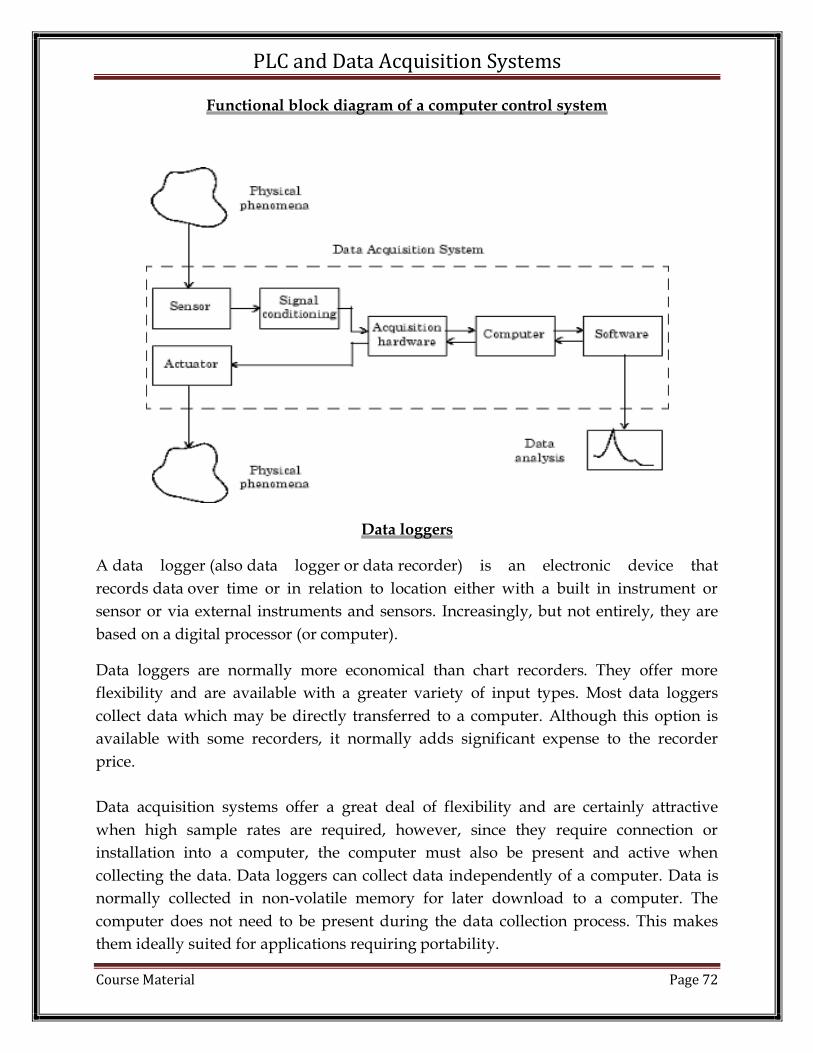
PLC and Data Acquisition Systems
Course Material Page 72
Functional block diagram of a computer control system
Data loggers
A data logger (also data logger or data recorder) is an electronic device that
records data over time or in relation to location either with a built in instrument or
sensor or via external instruments and sensors. Increasingly, but not entirely, they are
based on a digital processor (or computer).
Data loggers are normally more economical than chart recorders. They offer more
flexibility and are available with a greater variety of input types. Most data loggers
collect data which may be directly transferred to a computer. Although this option is
available with some recorders, it normally adds significant expense to the recorder
price.
Data acquisition systems offer a great deal of flexibility and are certainly attractive
when high sample rates are required, however, since they require connection or
installation into a computer, the computer must also be present and active when
collecting the data. Data loggers can collect data independently of a computer. Data is
normally collected in non-volatile memory for later download to a computer. The
computer does not need to be present during the data collection process. This makes
them ideally suited for applications requiring portability.

PLC and Data Acquisition Systems
Course Material Page 73
Wireless Data Loggers
Wireless data logger that measures and records ambient pressure, humidity and
temperature. This type of dynamic data logger is ideal for monitoring weather data,
measuring barometric pressure in high-rise buildings or monitoring storage or
warehouse environments that contain sensitive material
Miniature Single Input Data Loggers
Miniature single input data loggers are generally low cost loggers dedicated to a
specific input type. These types of data loggers are often used in the transportation
industry. A typical application would be to include a temperature data logger in a
shipment of food products to insure that the food temperature does not exceed
acceptable limits. In addition to temperature miniature data loggers are available for a
large variety of input types. most input types.
Fixed Mount Multi-Channel Data Loggers
Fixed input loggers have a fixed number of input channels which are generally
dedicated for a specific type of input. OMEGA offers fixed input data loggers ranging
from one to 8 channels
Handheld Multi-Channel Data Loggers
Handheld multi-channel loggers are commonly used in applications where the data
logger is to be carried from one location to another. They are also commonly used in
bench top or laboratory environments. In addition to storing data internally some
models even contain on board printers which can produce an immediate hardcopy of
the data.
Modular Data Loggers
A modular data logger is configurable and expandable through the use of plug-in
modules. The modules are normally field configurable and the user has the option of
adding as many channels to satisfy the application requirement.

PLC and Data Acquisition Systems
Course Material Page 74
Direct Digital Control (DDC)
Developments in digital electronics have led to many industrial processes being
computer controlled. The first system used was Direct Digital Control (DDC), in which
a computer measured each variable in the process, these signals being used to maintain
the required set points in the process.
As digital electronics developed, minicomputers become more competitive, and with
the advent of electronic Multiplexer (Mux) and Demultiplexer (Demux), it is possible
to sample the state of many analog and digital transducers at high speed and also to
control many values or devices in the plant.
A basic Direct Digital Control System is shown in Fig. In this system a large number
of transducers are sited around the plant, each transducer being connected to one input
of a Mux. A Mux can be considered as- the electronic equivalent of a switch with a
contact or blade which rotates very rapidly so that it moves from one transducer to
another, the blade remaining in contact with the transducer long enough for an ADC to
sample and digitise or to quantise the analog signal. The quantised data are then
transmitted along the data bus of the system to the CPU.

PLC and Data Acquisition Systems
Course Material Page 75
When the CPU has analysed the data from one or more transducers and has compared
them with the appropriate set points in the computer program, it sends signals along
the data bus to the values controlling the system as follows. The digital signal produced
by the CPU is converted into an analog signal by a DAC and the analog signal is
transmitted to the appropriate control value through a demux. As this is being
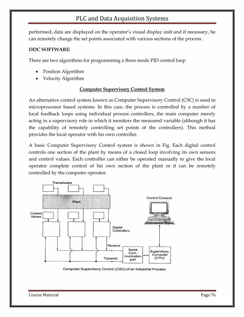
PLC and Data Acquisition Systems
Course Material Page 76
performed, data are displayed on the operator’s visual display unit and if necessary, he
can remotely change the set points associated with various sections of the process.
DDC SOFTWARE:
There are two algorithms for programming a three mode PID control loop
Position Algorithm
Velocity Algorithm
Computer Supervisory Control System
An alternative control system known as Computer Supervisory Control (CSC) is used in
microprocessor based systems. In this case, the process is controlled by a number of
local feedback loops using individual process controllers, the main computer merely
acting in a supervisory role in which it monitors the measured variable (although it has
the capability of remotely controlling set points of the controllers). This method
provides the local operator with his own controller.
A basic Computer Supervisory Control system is shown in Fig. Each digital control
controls one section of the plant by means of a closed loop involving its own sensors
and control values. Each controller can either be operated manually to give the local
operator complete control of his own section of the plant or it can be remotely
controlled by the computer operator.

PLC and Data Acquisition Systems
Course Material Page 77
The computer is connected to each controller by means of a communication port which
allows the computer either to receive information from the process controllers or
to transmit data to the controllers to change, say, a set point. To minimise the cost of
cabling, the communication port operates in a serial mode, that is, the data are sent
along the communicating link in the form of pulses (which requires only two wires —
a “send” wire and a “receive” wire). This method is clearly more economical than
using a 8-bit data bus throughout the plant, but it is slower in operation, since it takes
more time to send eight individual bits along one wire then it takes to send 8-bits
simultaneously along eight wires. The digital process controller (also called the central
computer) must contain a special interface which converts the pulses it receives in a
serial mode along the supervisory serial data bus into the parallel mode used
in microprocessor chip itself. Such an interface is known as a UART (Universal
Asynchronous Receiver/Transmitter).
Supervisory Control and Data Acquisition - SCADA System
SCADA stands for supervisory control and data acquisition. It is a type of software
application program for process control. SCADA is a central control system which
consists of controllers network interfaces, input/output, communication equipment,
and software. SCADA systems are used to monitor and control the equipment in the
industrial process which includes manufacturing, production, development, and
fabrication. The infrastructural processes include gas and oil distribution, electrical
power, water distribution. Public utilities include bus traffic system, airport. The
SCADA system takes the reading of the meters and checks the status of sensors in
regular intervals so that it requires minimal interference of humans.
A large number of processes occur in large industrial establishments. Every process you
need to monitor is very complex because each machine gives a different output. The
SCADA system used to gather data from sensors and instruments located in remote
areas. The computer then processes this data and presents it promptly. The SCADA
system gathers the information (like a leak on a pipeline occurred) and transfers the
information back to the system while giving the alerts that leakage has occurred and
displays the information in a logical and organized fashion. The SCADA system used to
run on DOS and UNIX operating systems.
Generally, the SCADA system is a centralized system that monitors and controls the
entire area. It is a pure software package that is positioned on top of the hardware. A
supervisory system gathers data on the process and sends the commands control to the
process. The SCADA is a remote terminal unit which is also known as RTU. Most

PLC and Data Acquisition Systems
Course Material Page 78
control actions are automatically performed by RTUs or PLCs. The RTUs consists of the
programmable logic converter which can be set to specific requirement. For example, in
the thermal power plant, the water flow can be set to a specific value or it can be
changed according to the requirement.
The SCADA system allows operators to change the set point for the flow, and enable
alarm conditions in case of loss of flow and high temperature, and the condition is
displayed and recorded. The SCADA system monitors the overall performance of the
loop. The SCADA system is a centralized system to communicate with both wired and
wireless technology to Clint devices. The SCADA system controls can run completely
all kinds of the industrial process.
Hardware Architecture:
The generally SCADA system can be classified into two parts:
The Clint layer which caters for the man-machine interaction.
The data server layer which handles most of the process data activities.
The SCADA station refers to the servers and it is composed of a single PC. The
data servers communicate with devices in the field through process controllers like
PLCs or RTUs. The PLCs are connected to the data servers either directly or via
networks or buses. The SCADA system utilizes a WAN and LAN networks, the WAN
and LAN consist of internet protocols used for communication between the master

PLC and Data Acquisition Systems
Course Material Page 79
station and devices. The physical equipment like sensors connected to the PLCs or
RTUs. The RTUs convert the sensor signals to digital data and sends digital data to the
master. According to the master feedback received by the RTU, it applies the electrical
signal to relays. Most of the monitoring and control operations are performed by RTUs
or PLCs as we can see in the figure.
Software Architecture
Most of the servers are used for multitasking and real-time database. The servers are
responsible for data gathering and handling. The SCADA system consists of a software
program to provide trending, diagnostic data, and manage information such as
scheduled maintenance procedures, logistic information, detailed schematics for a
particular sensor or machine, and expert-system troubleshooting guides. This means the
operator can see a schematic representation of the plant being controlled.
EX: alarm checking, calculations, logging, and archiving; polling controllers on a set of
parameters, those are typically connected to the server.

PLC and Data Acquisition Systems
Course Material Page 80
Working Procedure of SCADA system
The SCADA system performs the following functions:
Data Acquisitions
Data Communication
Information/Data presentation
Monitoring/Control
These functions are performed by sensors, RTUs, controller, a communication
network. The sensors are used to collect the important information and RTUs
are used to send this information to the controller and display the status of the
system. According to the status of the system, the user can give the command to
other system components. This operation is done by the communication
network.
Data Acquisitions:
The real-time system consists of thousands of components and sensors. It is very
important to know the status of particular components and sensors. For example,
some sensors measure the water flow from the reservoir to the water tank and some
sensors measure the value pressure as the water is a release from the reservoir.
Data Communication:
The SCADA system uses a wired network to communicate between users and devices.
Real-time applications use a lot of sensors and components which should be controlled
remotely. The SCADA system uses internet communications. All information is
transmitted through the internet using specific protocols. Sensor and relays are not
able to communicate with the network protocols so RTUs used to communicate
sensors and network interfaces.
Information/Data presentation: The normal circuit networks have some indicators
which can be visible to control but in the real-time SCADA system, there are thousands
of sensors and alarm which are impossible to be handled simultaneously. The SCADA
system uses the human-machine interface (HMI) to provide all of the information
gathered from the various sensors.
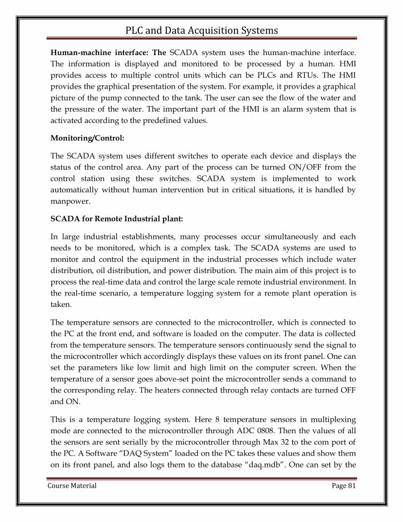
PLC and Data Acquisition Systems
Course Material Page 81
Human-machine interface: The SCADA system uses the human-machine interface.
The information is displayed and monitored to be processed by a human. HMI
provides access to multiple control units which can be PLCs and RTUs. The HMI
provides the graphical presentation of the system. For example, it provides a graphical
picture of the pump connected to the tank. The user can see the flow of the water and
the pressure of the water. The important part of the HMI is an alarm system that is
activated according to the predefined values.
Monitoring/Control:
The SCADA system uses different switches to operate each device and displays the
status of the control area. Any part of the process can be turned ON/OFF from the
control station using these switches. SCADA system is implemented to work
automatically without human intervention but in critical situations, it is handled by
manpower.
SCADA for Remote Industrial plant:
In large industrial establishments, many processes occur simultaneously and each
needs to be monitored, which is a complex task. The SCADA systems are used to
monitor and control the equipment in the industrial processes which include water
distribution, oil distribution, and power distribution. The main aim of this project is to
process the real-time data and control the large scale remote industrial environment. In
the real-time scenario, a temperature logging system for a remote plant operation is
taken.
The temperature sensors are connected to the microcontroller, which is connected to
the PC at the front end, and software is loaded on the computer. The data is collected
from the temperature sensors. The temperature sensors continuously send the signal to
the microcontroller which accordingly displays these values on its front panel. One can
set the parameters like low limit and high limit on the computer screen. When the
temperature of a sensor goes above-set point the microcontroller sends a command to
the corresponding relay. The heaters connected through relay contacts are turned OFF
and ON.
This is a temperature logging system. Here 8 temperature sensors in multiplexing
mode are connected to the microcontroller through ADC 0808. Then the values of all
the sensors are sent serially by the microcontroller through Max 32 to the com port of
the PC. A Software “DAQ System” loaded on the PC takes these values and show them
on its front panel, and also logs them to the database “daq.mdb”. One can set by the
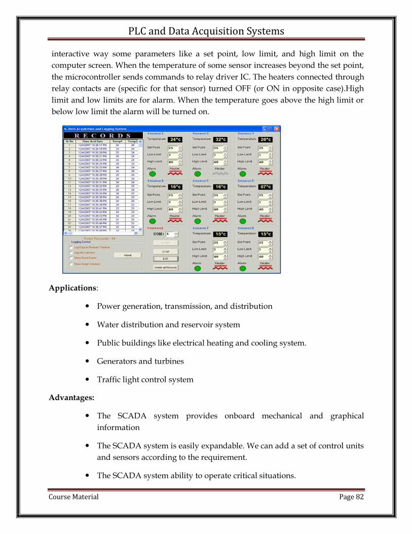
PLC and Data Acquisition Systems
Course Material Page 82
interactive way some parameters like a set point, low limit, and high limit on the
computer screen. When the temperature of some sensor increases beyond the set point,
the microcontroller sends commands to relay driver IC. The heaters connected through
relay contacts are (specific for that sensor) turned OFF (or ON in opposite case).High
limit and low limits are for alarm. When the temperature goes above the high limit or
below low limit the alarm will be turned on.
Applications:
Power generation, transmission, and distribution
Water distribution and reservoir system
Public buildings like electrical heating and cooling system.
Generators and turbines
Traffic light control system
Advantages:
The SCADA system provides onboard mechanical and graphical
information
The SCADA system is easily expandable. We can add a set of control units
and sensors according to the requirement.
The SCADA system ability to operate critical situations.

PLC and Data Acquisition Systems
Course Material Page 83
POST MCQ:
1. The control in SCADA is _____________
a) Online control
b) Direct control
c) Supervisory control
d) Automatic control
2. Which of the following is an example of the SCADA system?
a) Emerson Delta V
b) Honeywell PlantScape
c) Yokogawa CENTUM
d) PowerStudio Deluxe
3. How many levels are present in a complex SCADA system?
a) 3 – levels
b) 5 – levels
c) 4 – levels
d) 6 – levels
4. Which of the following is not the component of a SCADA system?
a) Database server
b) I/O system
c) PLC controller
d) Sparger controller
5. Which of the following is the heart of a SCADA system?
a) PLC
b) HMI
c) Alarm task
d) I/O task
Reference:
[1]. Frank D Petruzella, “Programmable Logic Controllers”, Third Ed 2005, Tata
McGraw Hill Education Private Limited.
[2]. Rockwell Automation, “Allen Bradley SLC 500 Instruction Set”, Reference
Manual.

PLC and Data Acquisition Systems
Course Material Page 84
UNIT 5
Data Acquisition Systems
AIM
To understand the design and operation of Sample and Hold circuit and Data
Acquisition Systems.
PRE-REQUSITE:
Linear Integrated Circuits
Digital Electronics
PRE-MCQ:
1. What is the main function of (A/D) or ADC converter?
a) Converts Digital to Analog Signal b) Converts Analog to Digital signal c) All of the mentioned d) None of the mentioned
2. What is the main function of (D/A) or DAC converter? a) Converts Digital to Analog Signal b) Converts Analog to Digital signal c) All of the mentioned d) None of the mentioned
3. Which is the major functioning responsibility of the multiplexing combinational circuit? a) Decoding the binary information b) Generation of all minterms in an output function with OR-gate c) Generation of selected path between multiple sources and a single destination d) Encoding of binary information
4. If the number of n selected input lines is equal to 2^m then it requires _____ select lines. a) 2 b) m c) n d) 2n
5. Demultiplexer act as an encoder. a) True b) False

PLC and Data Acquisition Systems
Course Material Page 85
Sampling
Sampling is defined as, “The process of measuring the instantaneous values of
continuous-time signal in a discrete form.”Sample is a piece of data taken from the
whole data which is continuous in the time domain. When a source generates an
analog signal and if that has to be digitized, having 1s and 0s i.e., High or Low, the
signal has to be discretized in time. This discretization of analog signal is called as
Sampling.
Sampling Rate
To digitize the signals, the gap between the samples should be fixed. That gap can be
termed as a sampling period Ts.
Sampling Frequency = 1/Ts =fs
Where,
Ts is the sampling time
fs is the sampling frequency or the sampling rate
Sampling frequency is the reciprocal of the sampling period. This sampling frequency,
can be simply called as Sampling rate. The sampling rate denotes the number of
samples taken per second, or for a finite set of values.
For an analog signal to be reconstructed from the digitized signal, the sampling rate
should be highly considered. The rate of sampling should be such that the data in the
message signal should neither be lost nor it should get over-lapped. Hence, a rate was
fixed for this, called as Nyquist rate.

PLC and Data Acquisition Systems
Course Material Page 86
Nyquist Rate
Suppose that a signal is band-limited with no frequency components higher than W Hertz. That means, W is the highest frequency. For such a signal, for effective reproduction of the original signal, the sampling rate should be twice the highest frequency.
fS=2W
Where,
fS is the sampling rate
W is the highest frequency
This rate of sampling is called as Nyquist rate.
A theorem called, Sampling Theorem, was stated on the theory of this Nyquist rate.
Aliasing
Aliasing can be referred to as “the phenomenon of a high-frequency component in the spectrum of a signal, taking on the identity of a low-frequency component in the spectrum of its sampled version.”
The corrective measures taken to reduce the effect of Aliasing are −
In the transmitter section of PCM, a low pass anti-aliasing filter is employed, before the sampler, to eliminate the high frequency components, which are unwanted.
The signal which is sampled after filtering, is sampled at a rate slightly higher than the Nyquist rate.
This choice of having the sampling rate higher than Nyquist rate, also helps in the easier design of the reconstruction filter at the receiver.
Quantizing
The digitization of analog signals involves the rounding off of the values which are
approximately equal to the analog values. The method of sampling chooses a few
points on the analog signal and then these points are joined to round off the value to a
near stabilized value. Such a process is called as Quantization.

PLC and Data Acquisition Systems
Course Material Page 87
Quantizing an Analog Signal
The analog-to-digital converters perform this type of function to create a series of digital values out of the given analog signal. The following figure represents an analog signal. This signal to get converted into digital, has to undergo sampling and quantizing.
The quantizing of an analog signal is done by discretizing the signal with a number of quantization levels. Quantization is representing the sampled values of the amplitude by a finite set of levels, which means converting a continuous-amplitude sample into a discrete-time signal.
The following figure shows how an analog signal gets quantized. The blue line represents analog signal while the brown one represents the quantized signal.
Both sampling and quantization result in the loss of information. The quality of a Quantizer output depends upon the number of quantization levels used. The discrete amplitudes of the quantized output are called as representation levels or reconstruction levels. The spacing between the two adjacent representation levels is called a quantum or step-size.
The following figure shows the resultant quantized signal which is the digital form for the given analog signal.

PLC and Data Acquisition Systems
Course Material Page 88
Types of Quantization
There are two types of Quantization - Uniform Quantization and Non-uniform Quantization.
The type of quantization in which the quantization levels are uniformly spaced is termed as a Uniform Quantization. The type of quantization in which the quantization levels are unequal and mostly the relation between them is logarithmic, is termed as a Non-uniform Quantization.
There are two types of uniform quantization. They are Mid-Rise type and Mid-Tread type. The following figures represent the two types of uniform quantization.
Figure 1 shows the mid-rise type and figure 2 shows the mid-tread type of uniform quantization.
The Mid-Rise type is so called because the origin lies in the middle of a raising part of the stair-case like graph. The quantization levels in this type are even in number.
The Mid-tread type is so called because the origin lies in the middle of a tread of the stair-case like graph. The quantization levels in this type are odd in number.
Both the mid-rise and mid-tread type of uniform quantizers are symmetric about the origin.

PLC and Data Acquisition Systems
Course Material Page 89
Quantization Error
For any system, during its functioning, there is always a difference in the values of its input and output. The processing of the system results in an error, which is the
difference of those values.
The difference between an input value and its quantized value is called a Quantization
Error.
Quantization Noise
It is a type of quantization error, which usually occurs in analog audio signal, while quantizing it to digital. For example, in music, the signals keep changing continuously, where regularity is not found in errors. Such errors create a wideband noise called as Quantization Noise.
Sample and Hold Circuit
A Sample and Hold Circuit, sometimes represented as S/H Circuit or S & H Circuit, is usually used with an Analog to Digital Converter to sample the input analog signal and hold the sampled signal.
In the S/H Circuit, the analog signal is sampled for a short interval of time, usually in
the range of 10µS to 1µS. After this, the sampled value is hold until the arrival of next input signal to be sampled. The duration for holding the sample will be usually between few milliseconds to few seconds.
The following image shows a simple block diagram of a typical Sample and Hold Circuit.
Need for Sample and Hold Circuits
If the input analog voltage of an ADC changes more than ±1/2 LSB, then there is a severe chance that the output digital value is an error. For the ADC to produce accurate

PLC and Data Acquisition Systems
Course Material Page 90
results, the input analog voltage should be held constant for the duration of the conversion.
As the name suggests, a S/H Circuit samples the input analog signal based on a sampling command and holds the output value at its output until the next sampling command is arrived.
The following image shows the input and output of a typical Sample and Hold Circuit
Simple Sample and Hold Circuit
Let us understand the operating principle of a S/H Circuit with the help of a simplified circuit diagram. This sample and hold circuits consist of two basic components:
Analog Switch Holding Capacitor
The following image shows the basic S/H Circuit.

PLC and Data Acquisition Systems
Course Material Page 91
This circuit tracks the input analog signal until the sample command is changed to hold
command. After the hold command, the capacitor holds the analog voltage during the
analog to digital conversion.
Advantages of Sample and Hold Circuit
The main and important advantage of a typical SH Circuit is to aid an Analog to Digital Conversion process by holding the sampled analog input voltage.
In multichannel ADCs, where synchronization between different channels is important, an SH circuit can help by sampling analog signals from all the channels at the same time.
In multiplexed circuits, the crosstalk can be reduced with an SH circuit.
Applications of Sample and Hold Circuit
Some of the important applications are mentioned below:
Analog to Digital Converter Circuits (ADC) Digital Interface Circuits Operational Amplifiers Analog De-multiplexers Data distribution systems Storage of outputs of multiplexers Pulse Modulation Systems

PLC and Data Acquisition Systems
Course Material Page 92
Data Acquisition System:
A typical Data Acquisition System consists of individual sensors with the necessary signal conditioning, data conversion, data processing, multiplexing, data handling and
associated transmission, storage and display systems.
In order to optimize the characteristics of the system in terms of performance, handling capacity and cost, the relevant sub systems can be combined together. Analog Data Acquisition System is generally acquired and converted into digital form for the purpose of processing, transmission, display and storage. Processing may consist of a large variety of operations, ranging from simple comparison to complicated mathematical manipulations. It can be for such purposes as collecting information (averages, statistics), converting the data into a useful form (e.g., calculations of efficiency of motor speed, torque and power input developed), using data for controlling a process, performing repeated calculations to separate signals buried in the noise, generating information for display, and various other purposes.
Data may be transmitted over long distances (from one point to another) or short distances (from test centre to a nearby PC).
The data may be displayed on a digital panel or on a CRT. The same be stored temporarily (for immediate use) or permanently for ready reference later. Data acquisition generally relates to the process of collecting the input data in digital form as rapidly, accurately, and economically as necessary. The basic instrumentation used may be a DPM with digital outputs, a shaft digitizer, or a sophisticated high speed resolution device.
To match the input requirements with the output of the sensor, some form of scaling and offsetting is necessary, and this is achieved by the use of amplifier/ attenuators.
For converting analog information from more than one source, either additional transducers or multiplexers are employed. To increase the speed with which information is accurately converted, sample-hold circuits are used. (In some cases, for analog signals with extra-wide range, logarithmic conversion is used.)

PLC and Data Acquisition Systems
Course Material Page 93
Data Acquisition System Block Diagram:
The characteristics of the data acquisition system depend on both the properties of the analog data and on the processing carried out.
Based on the environment, a broad Classification of data acquisition system into two categories.
1. Those suitable for favourable environments (minimum RF interference and electromagnetic induction)
2. Those intended for hostile environments The former category may include, among other, laboratory instrument applications, test systems for collecting long term drift information on zeners, high calibration test instruments and routine measurements in research, as mass spectrometers and lock-in amplifiers. In these, the systems are designed to perform tasks oriented more towards making sensitive measurements than to problems of protecting the integrity of analog data.
The Classifications of data acquisition system specifically includes measure, protecting the integrity of the analog data under hostile conditions. Such measurement conditions arise in aircraft control systems, in electrical power systems, and in industrial process control systems. Most of these hostile measurement conditions require devices capable of a wide range of temperature operations, excellent shielding, and redundant paths for critical measurements and considerable processing of the digital data acquisition system.

PLC and Data Acquisition Systems
Course Material Page 94
On the other hand, laboratory measurements are performed over a narrow temperature range with much less electrical noise, employing high sensitivity and precision devices for higher accuracies and resolution. The important Factors to Consider When Setting up a Data Acquisition System are as follows.
1. Accuracy and resolution
2. Number of channels to be monitored
3. Analog or digital signal 4. Single channel or multichannel 5. Sampling rate per channel 6. Signal conditioning requirements of each channel 7. Cost
The various general Configuration of Data Acquisition System are
1. Single channel possibilities Direct conversion Pre-amplification and direct conversion Sample and hold, and conversion Pre-amplification, signal conditioning and any of the above 2. Multi channel possibilities Multiplexing the outputs of single channel converters Multiplexing the output of sample-hold circuits Multiplexing the inputs of sample-hold circuits Multiplexing low level data
Objectives of Data Acquisition System:
It must acquire the necessary data, at correct speed and at the correct Use of all data efficiently to inform the operator about the state of the It must monitor the complete plant operation to maintain on-line optimum and
safe operations. It must provide an effective human communication system and be able to
identify problem areas, thereby minimizing unit availability and maximizing unit through point at minimum cost.
It must be able to collect summaries and store data for diagnosis of operation and record purpose.
It must be able to compute unit performance indices using on-line, real-time data.
It must be flexible and capable of being expanded for future require It must be reliable, and not have a down time greater than 0.1%.
Single Channel Data Acquisition System:

PLC and Data Acquisition Systems
Course Material Page 95
A Single Channel Data Acquisition System consists of a signal conditioner followed by an analog to digital (A/D) converter, performing repetitive conversions at a free running, internally determined rate. The outputs are in digital code words including over range indication, polarity information and a status output to indicate when the output digits are valid. A Single Channel Data Acquisition System is shown in Figure. The digital outputs are further fed to a storage or printout device, or to a digital computer device, or to a digital computer for analysis. The popular Digital panel Meter (DPM) is a well known example of this. However, there are two major drawbacks in using it as a DAS.
1. It is slow and the BCD has to be changed into binary coding, if the output is to be processed by digital equipment.
2. While it is free running, the data from the A/D converter is transferred to the interface register at a rate determined by the DPM itself, rather than commands beginning from the external interface.
Analog to Digital Converters (A/D):
Analog to digital converters used for DAS applications are usually designed to receive external commands to convert and hold. For dc and low frequency signals, a dual slope type converter is often used. The advantage is that it has a linear averaging capability and has a null response for frequencies harmonically related to the integrating period.
A/D converters based on dual slope techniques are useful for conversion of low
frequency data, such as from thermocouples, especially in the presence of noise. The most popular type of converter for data system applications is the successive approximation type, since it is capable of high resolution and high speed at moderate cost. (For a conversion time of 10 μS, the maximum dv/dt for full scale and 0.1% resolution is about 1 V/ms, which is a considerable improvement.) Higher speeds are obtained by preceding the A/D converter by a sample hold (S/H). The sample hold is particularly required with successive approximation type A/D converters, since at higher rates of input change the latter generates substantial non-linearity errors because it cannot tolerate changes during the conversion process.
Direct digital conversion carried out near the signal source is very advantageous in
cases where data needs to be transmitted through a noisy environment. Even with a

PLC and Data Acquisition Systems
Course Material Page 96
high level signal of 10 V, an 8 bit converter (1/256 resolution) can produce 1 bit
ambiguity when affected by noise of the order of 40 mV.
Multi Channel Data Acquisition System:
The Multi Channel Data Acquisition System can be time shared by two or more input sources. Depending on the desired properties of the multiplexed system, a number of techniques are employed for such time shared measurements.
Multi-Channel Analog Multiplexed System:
The multi-channel DAS has a single A/D converter preceded by a multiplexer, as shown in Figure.
The individual analog signals are applied directly or after amplification and/or signal conditioning, whenever necessary, to the multiplexer. These are further converted to digital signals by the use of A/D converters, sequentially. For the most efficient utilization of time, the multiplexer is made to seek the next channel to be converted while the previous data stored in the sample/hold is converted to digital form. When the conversion is complete, the status line from the converter causes the
sample/hold to return to the sample mode and acquires the signal of the next channel.
On completion of acquisition, either immediately or upon command, the S/H is
switched to the hold mode, a conversion begins again and the multiplexer selects the
next channel. This method is relatively slower than systems where S/H outputs or even
A/D converter outputs are multiplexed, but it has the obvious advantage of low cost

PLC and Data Acquisition Systems
Course Material Page 97
due to sharing of a majority of sub-systems. Sufficient accuracy in measurements can be
achieved even without the S/H, in cases where signal variations are extremely slow.
Multiplexing the Outputs of Sample/Hold:
When a large number of channels are to be monitored at the same time (synchronously)
but at moderate speeds, the technique of multiplexing the outputs of the S/H is
particularly attractive. An individual S/H is assigned to each channel as shown in Fig.
17.6, and they are updated synchronously by a timing circuit.
The S/H outputs are connected to an A/D converter through a multiplexer, resulting in a sequential readout of the outputs.
(Applications that might require this approach include wind tunnel measurements, seismographic experimentation, radar and fire control systems. The event to be measured is often a one-shot phenomenon and information is required at a critical point during a one-shot event.) Multiplexing After A/D Conversion:
It is now economically feasible to employ an A/D converter for each analog input and
multiplex the digital outputs. Since each analog to digital converter (A/D) is assigned to
an individual channel, the conversion rate of the A/D need only be as fast as is needed
for that channel, compared to the higher rates that would be needed if it were used as in
a multi channel analog multiplexed system.

PLC and Data Acquisition Systems
Course Material Page 98
The parallel conversion scheme shown in Figure provides additional advantages in
industrial data acquisition systems where many strain gauges, thermocouples and
LVDTs are distributed over large plant areas. Since the analog signals are digitized at
the source, the digital transmission of the data to the data centre (from where it can go
on to a communication channel) can provide enhanced immunity against line frequency
and other ground loop interferences. The data converted to digital form is used to
perform logic operations and decisions. Based on the relative speed at which changes
occur in the data, the scanning rate can be increased or decreased.
Alternatively, input channels having slowly varying data can be pre-multiplexed in any
of the forms suggested earlier, so that a set of sequentially multiplexed sub channels can
then replace one channel of the main digital multiplexed system, as indicated in Figure.
Multiplexing Low Level Data:
A low level data multiplexing system, as shown in Fig. 17.8, enables the use of a single high quality data amplifier for handling multichannel low level inputs.

PLC and Data Acquisition Systems
Course Material Page 99
Individual amplifiers are used for each low level signal. Low level multiplexing can be
attractive when a large number of channels (25), all having low level outputs, need to be
used at moderate speeds. The use of individual channels is possible because of the
availability of high quality amplifiers at moderate cost. (A typical application is a 200
channel stress measurement system in a transmission tower set up.)
Several factors have to be considered to accomplish low level multiplexing successfully.
Guarding may have to be employed for every channel, and each individual guard may
have to be switched, so that the appropriate guard is driven by the common mode
pertaining to that channel. Problems of pickup gets more complicated and have to be
taken care of, to preempt the possibility of signal-to-signal, and even common mode-to
differential mode signal cross-talk.
Capacitance balance may need to be carried out. When the number of channels to be
multiplexed increases, the problems of stray capacitances and capacitive balance are
worsened. In the specific case of a 48 channel system, the input channels are subdivided
into groups of eight channels in the first tier. Each of these six subgroups are in turn
multiplexed by a six channel multiplexer on the second tier. The main advantage of
using this is the reduction of capacitance effects.
Computer Based Data Acquisition System:
Computer Based Data Acquisition System – If a large number of inputs are to be
measured, some equipment is needed to measure them and display the results in a
meaningful and operationally useful fashion. All this is possible with Data Acquisition
System, which utilizes a computer driven visual display unit (CRT) as an operator aid.
A screen display can be obtained within two seconds by pressing a button. Information
may be displayed only when called up. The screen display can be designed in several
ways, using a combination of graphical and numeric displays, so as to be of maximum
utility to the operator.

PLC and Data Acquisition Systems
Course Material Page 100
Data Acquisition System aids operate in the following manner.
Display information instantly in condensed, understandable and legible manner
so that it can be easily assimilated.
Display spatial as well as time variation.
Display vital parameters grouped together logically and concisely, eliminating
the need of looking at many scattered instruments.
Display CRT graphic displays of plant sub-systems.
Display short trends on a long and short term basis, as required.
Analyze the data and present the highest priority problem first, and display
operator guidance messages.
Analyze the data and present the derived data; do performance calculations to
depict the performance of several equipments and plants.
Display alarms, indicating abnormal plant operating conditions on the
Provide trending of analog variables on strip chart recorders, in the form of a
histogram on the CRT, and provide dynamic updating of parameters.
Produce a hard copy record of all plant operating events and various plant
Provide a recording of the sequence of events, whenever an emergency occurs.
Post MCQ:
1. The time required to complete the conversion of Analog to Digital is ________ the duration of the hold mode of S/H. a) Greater than b) Equals to c) Less than d) Greater than or Equals to
2. In A/D converter, what is the time relation between sampling period T and the duration of the sample mode and the hold mode? a) Should be larger than the duration of sample mode and hold mode b) Should be smaller than the duration of sample mode and hold mode c) Should be equal to the duration of sample mode and hold mode d) Should be larger than or equals to the duration of sample mode and hold mode
3. To avoid aliasing a) Reduce the bandwidth b) Cut out high frequency

PLC and Data Acquisition Systems
Course Material Page 101
c) Reduce the bandwidth & Cut out high frequency d) None of the mentioned
4. The signal can be reconstructed a) At Nyquist rate b) Above Nyquist rate c) At & above the Nyquist rate d) None of the mentioned
5. How many select lines would be required for an 8-line-to-1-line multiplexer? a) 2 b) 4 c) 8 d) 3
Reference:
[1]. Frank D Petruzella, “Programmable Logic Controllers”, Third Ed 2005, Tata
McGraw Hill Education Private Limited.
[2]. Rockwell Automation, “Allen Bradley SLC 500 Instruction Set”, Reference
Manual.
[3]. https://www.electronicshub.org
[4]. https://www.eeeguide.com
LABORATORY SIMULATION EXAMPLES:
1. Design ladder logic for the following automatic sequential control.
a. The Lube-oil pump motor starter coil M1 should energize when the start
pushbutton PB2 is momentarily actuated.
b. When the Lube-oil pump builds up sufficient oil pressure, the lube-oil
pressure switch PS1 closes automatically.
c. This PS1 in turn should energize M2.
d. The energize coil M3 should turn on after M2 with a delay of 15 seconds.
Solution:

PLC and Data Acquisition Systems
Course Material Page 102
2. Design ladder logic for the following automatic sequential control.
a. Closing the switch S1 should turn ON the motors M1, M2 and M3
immediately.
b. When the switch S1 is opened, the motors M1, M2 and M3 should turn OFF
with five second intervals.
Solution:

PLC and Data Acquisition Systems
Course Material Page 103
3. Design ladder logic for the following automatic sequential control.
a. Turn ON the Pilot Light (PL1)with a delay of 45,000 seconds after the switch
PS1 is closed.
(Note the maximum delay given by a single timer instruction is 36,000
seconds)
Solution:
Since the total delay to turn on the output PL1 is 45000 seconds, we can’t use a single
timer. In order to achieve the high delay time we have to cascade the timer instructions.
The first timer T4:0 will give 30000 seconds delay and timer two will give the remaining
15000 seconds delay to the output PL1.
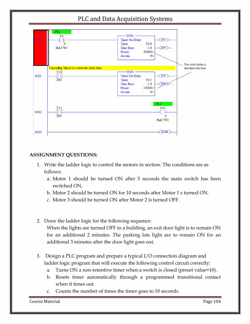
PLC and Data Acquisition Systems
Course Material Page 104
ASSIGNMENT QUESTIONS:
1. Write the ladder logic to control the motors in section. The conditions are as
follows:
a. Motor 1 should be turned ON after 5 seconds the main switch has been
switched ON.
b. Motor 2 should be turned ON for 10 seconds after Motor 1 s turned ON.
c. Motor 3 should be turned ON after Motor 2 is turned OFF.
2. Draw the ladder logic for the following sequence:
When the lights are turned OFF in a building, an exit door light is to remain ON
for an additional 2 minutes. The parking lots light are to remain ON for an
additional 3 minutes after the door light goes out.
3. Design a PLC program and prepare a typical I/O connection diagram and
ladder logic program that will execute the following control circuit correctly:
a. Turns ON a non-retentive timer when a switch is closed (preset value=10).
b. Resets timer automatically through a programmed transitional contact
when it times out.
c. Counts the number of times the timer goes to 10 seconds.

PLC and Data Acquisition Systems
Course Material Page 105
d. Resets counter automatically through a second programmed transitional
contact at the count of 5.
e. Latches ON a light at the count of 5.
f. Resets the light to OFF and counter to 0 when a selector switch is closed.
4. Draw the ladder logic for the following sequence:
For a grinding operation on a metal part, the coolant flow on the part must be on
for an interval before the grinding process starts. When the process circuit is
turned on, the coolant motor (CM) is turned ON. Five seconds later the grinding
process (GM) starts.
5. Develop Ladder logic for: A and B are turned ON by a switch when the switch is
turned OFF A goes OFF, immediately. B remains ON for another 20 seconds and
then goes OFF.