Platform and Formwork System for Cooling Towers · lever arms or other tools provided together with...
52
07/2009 User’s Manual MESA - CTP Platform and Formwork System for Cooling Towers
-
Upload
truongkiet -
Category
Documents
-
view
216 -
download
0
Transcript of Platform and Formwork System for Cooling Towers · lever arms or other tools provided together with...

07/2009 User’s Manual
MESA - CTP Platform and Formwork System for
Cooling Towers

Contents
Remarks
General Remarks 1
Safety Remarks 2
Introduction
System Description 3
Working Limits 5
System Overview 7
Workflow and Climbing Order 14
Loading Limits on Platform Levels 20
Operation
Climbing Phases 22
Formwork and Climbing Operation 26
Concreting of First Three Rings 43
General Maintenance
General Inspection and Maintenance 46
Motor - Electrical Circuit Diagram 47
Wiring Scheme 48

Remarks Cooling Tower Platform System - CTP
USER’S MANUAL – 07-2009 1
www.mesaimalat.com.tr
GENERAL REMARKS
• This “User’s Manual” contains information about MESA-Formwork & Scaffolding systems. It describes setting up, utilisation, correction, maintenance and loading data of these products and systems, by helping to the site as a ‘Method Statement’. • MESA products could only be used according to the Instruction or User’s Manuals, any Technical Details given in Documents provided by MESA. • Due to avoid unwanted results such as accidents and damage to health or material damages, Owner and User of MESA products or Systems should comply the directions given by the documents and data explained above. • In the cases which requires different deviations from these manuals, Owner or User of MESA products or systems must check the evidence of the technical solutions or supplementary instruction methods and procure revised static or dynamic calculations to MESA. • Although these User’s Manual have to be read before installation or any usage; in order to provide all requirements of safety on site, user should take necessary precautions according to the international safety regulations and local safety rules. • Schematic illustrations on this manual give only basic rules to be applied during assembly, erection and dismantling, therefore it not complete from the safety point of view. • User should inspect and check the products and systems before use. Materials not having suitable conditions such as damaging and weakening due to rust, corrosion or wear, should be removed and reported to MESA immediately. • Since combination of any material and component originated from other manufacturers with MESA products may be dangerous for health and property, they must not combined with MESA products. In such a case, customer should contact with MESA.
• Only the skilled persons educated according to official documents of MESA are authorised to assemble, erect and dismantle of MESA products and systems. • Users working with MESA products and systems should read, understand and accept the information included in this manual. Otherwise, they should be trained by the customer according to MESA documentation.
• Users who will work with MESA-CTP Cooling Tower Platform and Formwork System should be educated and informed by skilled MESA personel.
• MESA will issue a “OPERATION CERTIFICATE” to persons that have undergone required training.
• If a person who do not have this “OPERATION CERTIFICATE”, he/she could not use MESA-CTP Platform and Formwork System.
Mesa Imalat reserves the right to make
technical changes in the interests of progress.
© Copyright by MESA Imalat San.ve Tic A.S.-Ankara-Turkey

Remarks Cooling Tower Platform System - CTP
USER’S MANUAL – 07-2009 2
www.mesaimalat.com.tr
SAFETY REMARKS
Symbols Used
Important Note
Warning
Sight-Check
Instruction
• During all set up procedure, loads must be safely transferred. • During all construction phases, all components and units must be safely stabilised. • According to the formwork system choosen, admissible fresh concrete pressure must not be exceeded. Such a case will cause to formwork overload and more deflection both on formwork and concrete, even breakage and overload on tie-rods. Maximum working load of tie-rods used must be checked. • Person who works on the system in all phases (i.e. setting up, erection, concreting, dismantling and disassembly etc.) should be assure to have enough and safe workplace. • The formwork removal must be done after the concrete has reached sufficient strength. • Formwork removal must be done by using lever arms or other tools provided together with the formwork system but not the crane or any other devices which will cause unwanted results. • In order to keep the scaffolding, platform, formwork or other parts stable and safe, user should check the conditions where the procedure occurs during the formwork removal procedure. • Any small parts used in the system should be fixed in their place to avoid loosing or falling freely. • All connecting parts must be used properly to provide correct functioning of them. Selecting of wrong part could cause leakage of the relevant products under loading. • All connections must be checked periodically. Especially bolt and nut connections and pin connections should be controlled. • Enough number of Fire Extinguishers and any other necessary items against danger of fire should be kept available where the formwork and scaffolding systems need.

Introduction Cooling Tower Platform System - CTP
USER’S MANUAL – 07-2009 3
www.mesaimalat.com.tr
SYSTEM DESCRIPTION

Introduction Cooling Tower Platform System - CTP
USER’S MANUAL – 07-2009 4
www.mesaimalat.com.tr
MESA-CTP Cooling Tower Platform System
MESA-CTP Platform and Formwork System is designed and manufactured for construction of hyperparaboloidal cooling towers.
Basically, system is electromechanically powered for climbing operation and has steel faced formwork for concreting.
It provides high degree of accuracy with clean concrete surface with a minimum labour cost.
Formwork
Formwork used in the system allows good concrete surface and smooth construction joints to make easy the application of any kind of coating for protection.
Steel sheet having 4 mm thickness is especially produced for concreting and it gives high number of concreting cycles.
Formwork height is 1750 mm to obtain 1500 mm height of concrete in one casting.
As main panels have 5500 mm width, they are completed with 100 mm fixed fillers and 300 mm adjustable fillers to compensate the net dimensions varying with different diameters of cooling towers due to hyperparaboloidal section of it.
Main panel in the outside has necessary curves for two wind ribs having a fix dimension to each other. Other two wind ribs in each side of the main panel are obtained by the adjustable fillers.
Main panel in the outside has necessary curves for two wind ribs having a fix dimension to each other. Other two wind ribs in each side of the main panel are obtained by the adjustable fillers.
Inclination of formwork is provided by special props fixed on a carriage located on the Main Platforms.
Since the system has its own climbing power unit, it obviates crane requirement for climbing.
Each individual platform is mounted on the wall by two suspension shoes.
Basic climbing principle is to climb the lifting frame and suspend it to the shoes and fix it firstly and then to climb the main frame by the same way.
The shoes in the lower level and the current level will guide the frames basically.
Cooling Tower Platform-CTP
CTP is divided into two main part ;
- Main Frame where all necessary operations (i.e.concreting, reinforcement working, pre-working before climbing etc.) are done.
Main Frame consists four working platforms in different levels.
These are Reinforcement Platform on top, Main Platform where the formworks exist, Climbing Platform where the climbing operation is realised, and the Lower Platform to dismantle the anchors and shoes to be used in next operation.
- Lifting Frame which helps to climb the Main Frame to the next level of construction.
Main Frames are connected to each other by connection platforms on the Reinforcement Platform levels, Main Platform levels and Lower Platform levels.
Electro-mechanical power unit is also located on this frame. This power unit includes one set of jack and rack bar for each Lifting Frame and one set of motor-gear assembly given in a quantity which is enough to climb all platforms as five or six separate modules respectively.

Introduction Cooling Tower Platform System - CTP
USER’S MANUAL – 07-2009 5
www.mesaimalat.com.tr
WORKING LIMITS
Introduction Cooling Tower Platform System - CTP
USER’S MANUAL – 07-2009 6
www.mesaimalat.com.tr
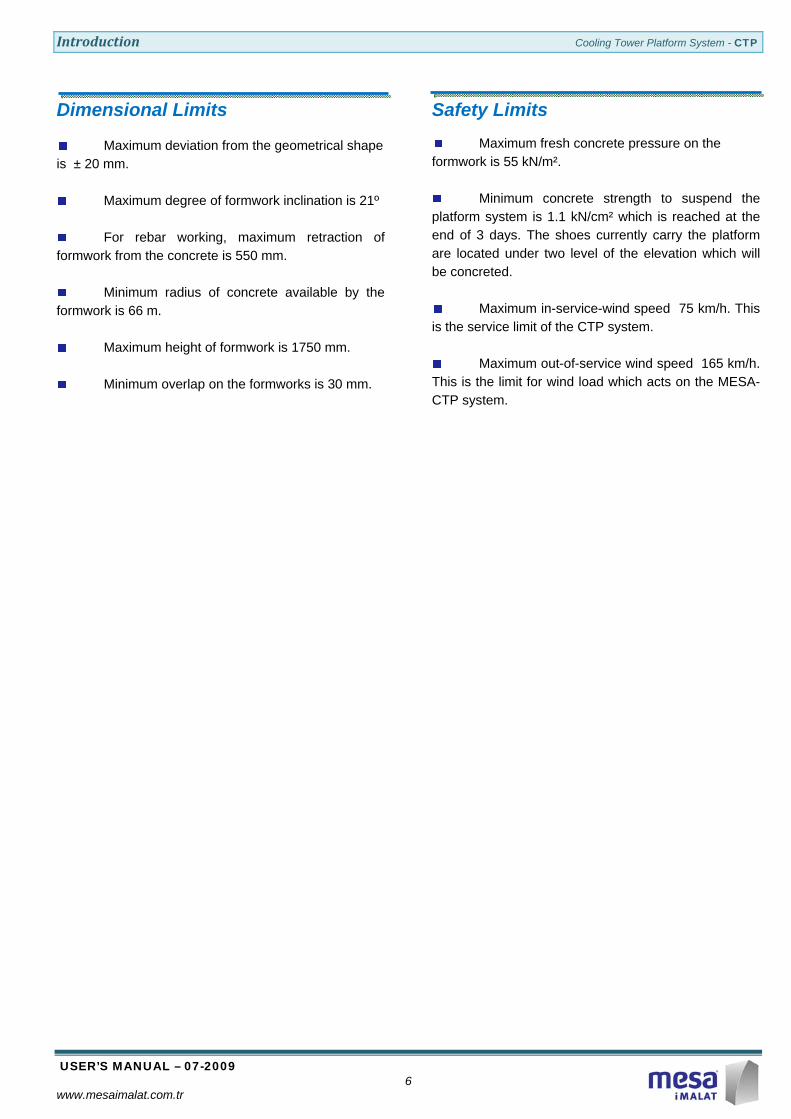
Dimensional Limits
Maximum deviation from the geometrical shape is ± 20 mm.
Maximum degree of formwork inclination is 21º
For rebar working, maximum retraction of formwork from the concrete is 550 mm.
Minimum radius of concrete available by the formwork is 66 m.
Maximum height of formwork is 1750 mm.
Minimum overlap on the formworks is 30 mm.
Safety Limits
Maximum fresh concrete pressure on the formwork is 55 kN/m².
Minimum concrete strength to suspend the platform system is 1.1 kN/cm² which is reached at the end of 3 days. The shoes currently carry the platform are located under two level of the elevation which will be concreted.
Maximum in-service-wind speed 75 km/h. This is the service limit of the CTP system.
Maximum out-of-service wind speed 165 km/h. This is the limit for wind load which acts on the MESA-CTP system.

Introduction Cooling Tower Platform System – CTP
USER’S MANUAL – 07-2009 7
www.mesaimalat.com.tr
SYSTEM OVERVIEW

Introduction Cooling Tower Platform System – CTP
USER’S MANUAL – 07-2009 8
www.mesaimalat.com.tr
EXTERIOR CTP INTERIOR CTP
Legends
Stable Platforms I - Reinforcement Platform II - Main Platform III - Climbing Platform IV - Lower Platform
Assemblies (See Sections) A - Outside Formwork B - Inside Formwork C - Formwork Carriage D - Tie-Rod Assembly E - Conical Anchor Assembly F - Suspension Shoe (Upper case) G - Suspension Shoe (Lowercase)
Parts
1 - Inclined Prop 2 - Adjusting Prop 3 - Measuring Plate 4 - Fixing Jack of Lifting Frame 5 - Fixing Jack of Main Frame
I
B 1
3
D
C
F
2
E
4
5
A
II
III
IV
G

Introduction Cooling Tower Platform System – CTP
USER’S MANUAL – 07-2009 9
www.mesaimalat.com.tr
EXTERIOR CTP
Legends Main Parts V - Lifting Frame VI - Main Frame VII - Connection Platforms
Assemblies (See Sections) H – Jack-Rack Bar Assembly J – Motor-Gear Box Assembly
Parts
1 – Main Panel 2 – 100mm Fixed Filler 3 – Sliding Panel 4 – Adjusting Filler (w/RIB) 5 – Safety Wing-Nut 6 – Stability Bar
V
VI
VII
VII
H
5
6
2
3
1
4

Introduction Cooling Tower Platform System – CTP
USER’S MANUAL – 07-2009 10
www.mesaimalat.com.tr
Assemblies
A – Outside Formwork
Legend
1 – Angled Filler 2 – Main Panel 3 – 100mm Fixed Filler 4 – Adjusting Filler (w/RIB)
2
1
4
3

Introduction Cooling Tower Platform System – CTP
USER’S MANUAL – 07-2009 11
www.mesaimalat.com.tr
B – Inside Formwork
Legend
1 – Angled Filler 2 – Main Panel 3 – 100mm Fixed Filler 4 – Adjusting Filler
1
2
3
4

Introduction Cooling Tower Platform System – CTP
USER’S MANUAL – 07-2009 12
www.mesaimalat.com.tr
C - Formwork Carriage
1 2 Legend 1 – Locking Screw 2 – Formwork Carriage D – Tie-Rod Assembly (w/tube spacer)
1 2 3 4 Legend 1 – Wing Nut 2 – Tube Spacer 3 – Tie-Rod (Ø15) 4 – Plate F – Suspension Shoe (Uppercase) 1 2 3 4 5 Legend 1 – Safety Pin 2 – Suspension Hook of Lifting Frame 3 – Bearing Pin 4 – Suspension Shoe 5 – Adjusting Screw
E – Conical Anchor Assembly
1 2 3
Legend 1 – Conical Anchor 2 – Anchor Tie 3 – Anchor Tie-nut D – Tie-Rod Assembly (w/cone spacer) 1 4 2 3 Legend 1 – Wing Nut 2 – Cone Spacer 3 – Tie-Rod (Ø15) 4 – Plate G – Suspension Shoe (Lowercase) 4 1 2 3 5 Legend 1 – Safety Pin 2 – Suspension Hook of Main Frame 3 – Bearing Pin 4 – Suspension Shoe 5 – Adjusting Screw

Introduction Cooling Tower Platform System – CTP
USER’S MANUAL – 07-2009 13
www.mesaimalat.com.tr
H – Jack-Rack Bar Assembly
1 2
Legend 1 – Jack 2 – Rack Bar
J – Motor-Gear Box Assembly 3 2 1 (One set for each five platforms) Legend 1 – Motor 2 – Gear Box 3 – Connection Bracket
K – Cable-Remote Control Unit
1 2 3 Legend 1 – Lock Switch 2 – UP Buton 3 – DOWN buton

Introduction Cooling Tower Platform System – CTP
USER’S MANUAL – 07-2009 14
www.mesaimalat.com.tr
WORKFLOW
and CLIMBING ORDER

Introduction Cooling Tower Platform System – CTP
USER’S MANUAL – 07-2009 15
www.mesaimalat.com.tr
between06.00 ‐ 07.30 h 1 2 3 4 5 6 7 8 9 10 11 12 13 14 15 16 17 18 19 20 21 22 23 24 25 26 27 28 29 30 31 32 33 34 35 36 37 38Formwork StrikingFormwork ClimbingFormwork Set‐UpConcretingRebar Working
between07.30 ‐ 09.00 h 1 2 3 4 5 6 7 8 9 10 11 12 13 14 15 16 17 18 19 20 21 22 23 24 25 26 27 28 29 30 31 32 33 34 35 36 37 38Formwork StrikingFormwork ClimbingFormwork Set‐UpConcretingRebar Working
between09.00 ‐ 10.30 h 1 2 3 4 5 6 7 8 9 10 11 12 13 14 15 16 17 18 19 20 21 22 23 24 25 26 27 28 29 30 31 32 33 34 35 36 37 38Formwork StrikingFormwork ClimbingFormwork Set‐UpConcretingRebar Working
between10.30 ‐ 12.00 h 1 2 3 4 5 6 7 8 9 10 11 12 13 14 15 16 17 18 19 20 21 22 23 24 25 26 27 28 29 30 31 32 33 34 35 36 37 38Formwork StrikingFormwork ClimbingFormwork Set‐UpConcretingRebar Working
Daily Construction Cycle
Clarify the working crews for Formwork Striking, CTP Climbing, Formwork Set-up, Concreting Rebar Working,
Table of Daily Construction Cycle
Set the diameter of Cooling Tower and the construction level
Depending on the weather conditions, experience of the working crew, Simple Daily Cycle according to the crews’ mission, is realised as follows ;

Introduction Cooling Tower Platform System – CTP
USER’S MANUAL – 07-2009 16
www.mesaimalat.com.tr
between13.30 ‐ 15.00 h 1 2 3 4 5 6 7 8 9 10 11 12 13 14 15 16 17 18 19 20 21 22 23 24 25 26 27 28 29 30 31 32 33 34 35 36 37 38Formwork StrikingFormwork ClimbingFormwork Set‐UpConcretingRebar Working
between15.00 ‐ 16.30 h 1 2 3 4 5 6 7 8 9 10 11 12 13 14 15 16 17 18 19 20 21 22 23 24 25 26 27 28 29 30 31 32 33 34 35 36 37 38Formwork StrikingFormwork ClimbingFormwork Set‐UpConcretingRebar Working
between18.00 ‐ 19.30 h 1 2 3 4 5 6 7 8 9 10 11 12 13 14 15 16 17 18 19 20 21 22 23 24 25 26 27 28 29 30 31 32 33 34 35 36 37 38Formwork StrikingFormwork ClimbingFormwork Set‐UpConcretingRebar Working
between16.30 ‐ 18.00 h 1 2 3 4 5 6 7 8 9 10 11 12 13 14 15 16 17 18 19 20 21 22 23 24 25 26 27 28 29 30 31 32 33 34 35 36 37 38Formwork StrikingFormwork ClimbingFormwork Set‐UpConcretingRebar Working
between12.00 ‐ 13.30 h 1 2 3 4 5 6 7 8 9 10 11 12 13 14 15 16 17 18 19 20 21 22 23 24 25 26 27 28 29 30 31 32 33 34 35 36 37 38Formwork StrikingFormwork ClimbingFormwork Set‐UpConcretingRebar Working

Introduction Cooling Tower Platform System – CTP
USER’S MANUAL – 07-2009 17
www.mesaimalat.com.tr
CTP No. 35 36 37 38 1 2 3 4 5 6 7 8 9 10 11
150 120 90 60 30 0
h (cm) CLIMBING ORDER ‐ 0
CTP No. 35 36 37 38 1 2 3 4 5 6 7 8 9 10 11
150 120 90 60 30 5M‐5 4M‐4 3M‐3 2M‐2 1M‐1
0
h (cm) CLIMBING ORDER ‐ 1
CTP No. 35 36 37 38 1 2 3 4 5 6 7 8 9 10 11
150 120 90 60 4M‐5 3M‐4 2M‐3 1M‐2
30 5M‐1
0
h (cm) CLIMBING ORDER ‐ 2
2M‐3
4M‐2
CTP Climbing Order
Legend
Stable CTP (no climbing)
3.rd climbing step of Motor no.3 in relevant climbing order
2.nd climbing step of Motor no.4 in relevant climbing order
All CTP’s are stable. No climbing operation. Prepare Motor-Gear Box
Assemblies for climbing operations.
Raise CTP 1 to 30 cm. (with Motor no.1)
Raise CTP 38 to 30 cm. (with Motor no.2)
Raise CTP 37 to 30 cm. (with Motor no.3)
Raise CTP 36 to 30 cm. (with Motor no.4)
Raise CTP 35 to 30 cm. (with Motor no.5)
Transfer Motor no.5 from CTP 35 to CTP 2 and raise CTP 2 to 30 cm.
Raise CTP 1 to 60 cm. (with Motor no.1)
Raise CTP 38 to 60 cm. (with Motor no.2)
Raise CTP 37 to 60 cm. (with Motor no.3)
Raise CTP 36 to 60 cm. (with Motor no.4)

Introduction Cooling Tower Platform System – CTP
USER’S MANUAL – 07-2009 18
www.mesaimalat.com.tr
CTP No. 35 36 37 38 1 2 3 4 5 6 7 8 9 10 11
150 120 90 3M‐5 2M‐4 1M‐3
60 5M‐2
30 4M‐1
0
h (cm) CLIMBING ORDER ‐ 3
CTP No. 35 36 37 38 1 2 3 4 5 6 7 8 9 10 11
150 120 2M‐5 1M‐4
90 5M‐3
60 4M‐2
30 3M‐1
0
h (cm) CLIMBING ORDER ‐ 4
CTP No. 35 36 37 38 1 2 3 4 5 6 7 8 9 10 11
150 1M‐5
120 5M‐4
90 4M‐3
60 3M‐2
30 2M‐1
0
h (cm) CLIMBING ORDER ‐ 5
CTP No. 35 36 37 38 1 2 3 4 5 6 7 8 9 10 11
150 5M‐5
120 4M‐4
90 3M‐3
60 2M‐2
30 1M‐1
0
h (cm) CLIMBING ORDER ‐ 6
Transfer Motor no.4 from CTP 36 to CTP 3 and raise CTP 3 to 30 cm.
Raise CTP 2 to 60 cm. (with Motor no.5)
Raise CTP 1 to 90 cm. (with Motor no.1)
Raise CTP 38 to 90 cm. (with Motor no.2)
Raise CTP 37 to 90 cm. (with Motor no.3)
Transfer Motor no.3 from CTP 37 to CTP 4 and raise CTP 4 to 30 cm.
Raise CTP 3 to 60 cm. (with Motor no.4)
Raise CTP 2 to 90 cm. (with Motor no.5)
Raise CTP 1 to 120 cm. (with Motor no.1)
Raise CTP 38 to 120 cm. (with Motor no.2)
Transfer Motor no.2 from CTP 38 to CTP 5 and raise CTP 5 to 30 cm.
Raise CTP 4 to 60 cm. (with Motor no.3)
Raise CTP 3 to 90 cm. (with Motor no.4)
Raise CTP 2 to 120 cm. (with Motor no.5)
Raise CTP 1 to 150 cm. (with Motor no.1)
Transfer Motor no.1 from CTP 1 to CTP 6 and raise CTP 6 to 30 cm.
Raise CTP 5 to 60 cm. (with Motor no.2)
Raise CTP 4 to 90 cm. (with Motor no.3)
Raise CTP 3 to 120 cm. (with Motor no.4)
Raise CTP 2 to 150 cm. (with Motor no.5)

Introduction Cooling Tower Platform System – CTP
USER’S MANUAL – 07-2009 19
www.mesaimalat.com.tr
CTP No. 35 36 37 38 1 2 3 4 5 6 7 8 9 10 11
150 4M‐5
120 3M‐4
90 2M‐3
60 1M‐2
30 5M‐1
0
h (cm) CLIMBING ORDER ‐ 7
CTP No. 35 36 37 38 1 2 3 4 5 6 7 8 9 10 11
150 3M‐5
120 2M‐4
90 1M‐3
60 5M‐2
30 4M‐1
0
h (cm) CLIMBING ORDER ‐ 8
CTP No. 35 36 37 38 1 2 3 4 5 6 7 8 9 10 11
150 2M‐5
120 1M‐4
90 5M‐3
60 4M‐2
30 3M‐1
0
h (cm) CLIMBING ORDER ‐ 9
CTP No. 35 36 37 38 1 2 3 4 5 6 7 8 9 10 11
150 1M‐5
120 5M‐4
90 4M‐3
60 3M‐2
30 2M‐1
0
h (cm) CLIMBING ORDER ‐ 10
Continue to the climbing operation as above order.
Transfer Motor no.5 from CTP 2 to CTP 7 and raise CTP 7 to 30 cm.
Raise CTP 6 to 60 cm. (with Motor no.1)
Raise CTP 5 to 90 cm. (with Motor no.2)
Raise CTP 4 to 120 cm. (with Motor no.3)
Raise CTP 3 to 150 cm. (with Motor no.4)
Transfer Motor no.4 from CTP 3 to CTP 8 and raise CTP 8 to 30 cm.
Raise CTP 7 to 60 cm. (with Motor no.5)
Raise CTP 6 to 90 cm. (with Motor no.1)
Raise CTP 5 to 120 cm. (with Motor no.2)
Raise CTP 4 to 150 cm. (with Motor no.3)
Transfer Motor no.3 from CTP 4 to CTP 9 and raise CTP 9 to 30 cm.
Raise CTP 8 to 60 cm. (with Motor no.4)
Raise CTP 7 to 90 cm. (with Motor no.5)
Raise CTP 6 to 120 cm. (with Motor no.1)
Raise CTP 5 to 150 cm. (with Motor no.2)
Transfer Motor no.2 from CTP 5 to CTP 10 and raise CTP10 to 30 cm.
Raise CTP 9 to 60 cm. (with Motor no.3)
Raise CTP 8 to 90 cm. (with Motor no.4)
Raise CTP 7 to 120 cm. (with Motor no.5)
Raise CTP 6 to 150 cm. (with Motor no.1)

Introduction Cooling Tower Platform System – CTP
USER’S MANUAL – 07-2009 20
www.mesaimalat.com.tr
LOADING LIMITS on PLATFORM LEVELS
Introduction Cooling Tower Platform System – CTP
USER’S MANUAL – 07-2009 21
www.mesaimalat.com.tr
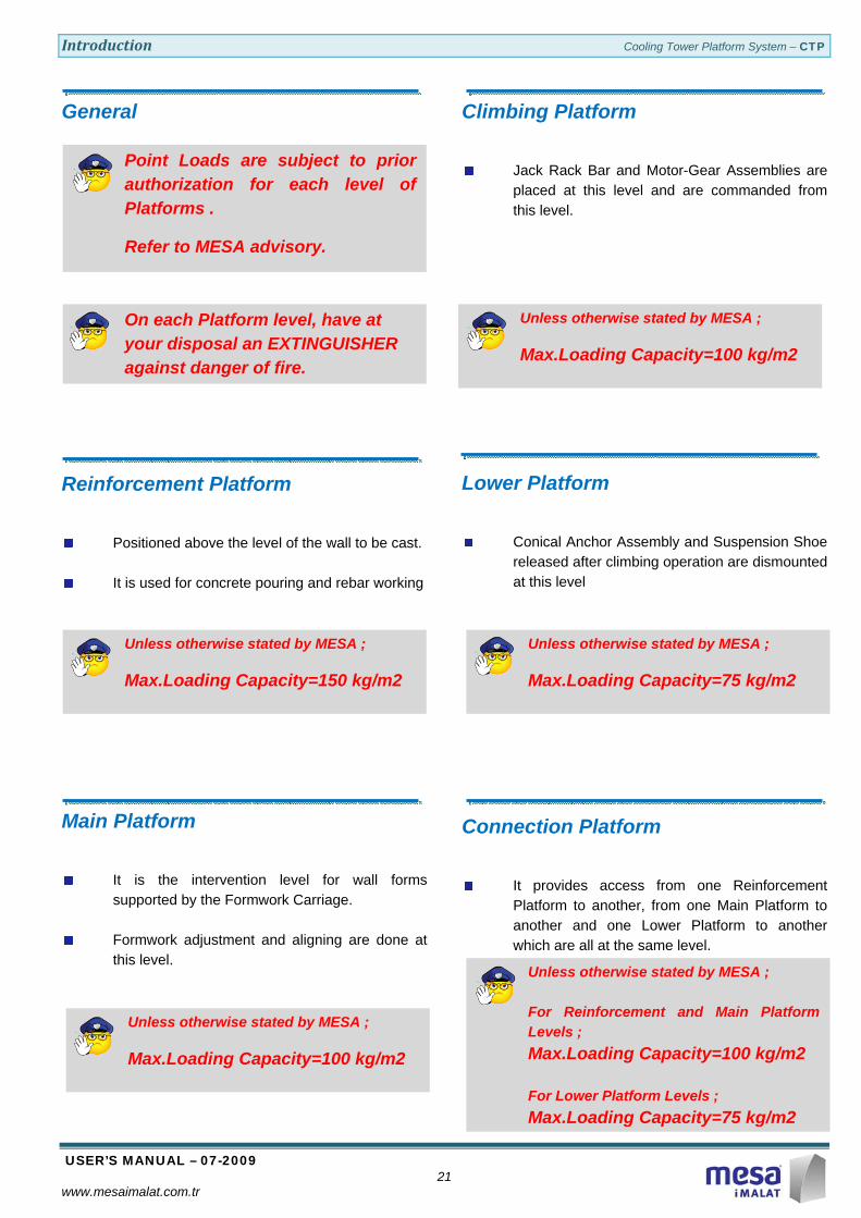
Unless otherwise stated by MESA ;
Max.Loading Capacity=150 kg/m2
Unless otherwise stated by MESA ;
Max.Loading Capacity=100 kg/m2
Unless otherwise stated by MESA ;
Max.Loading Capacity=100 kg/m2
Unless otherwise stated by MESA ;
Max.Loading Capacity=75 kg/m2
Point Loads are subject to prior authorization for each level of Platforms .
Refer to MESA advisory.
On each Platform level, have at your disposal an EXTINGUISHER against danger of fire.
Unless otherwise stated by MESA ;
For Reinforcement and Main Platform Levels ; Max.Loading Capacity=100 kg/m2 For Lower Platform Levels ; Max.Loading Capacity=75 kg/m2
General
Reinforcement Platform
Positioned above the level of the wall to be cast.
It is used for concrete pouring and rebar working
Main Platform
It is the intervention level for wall forms supported by the Formwork Carriage.
Formwork adjustment and aligning are done at this level.
Climbing Platform
Jack Rack Bar and Motor-Gear Assemblies are placed at this level and are commanded from this level.
Lower Platform
Conical Anchor Assembly and Suspension Shoe released after climbing operation are dismounted at this level
Connection Platform
It provides access from one Reinforcement Platform to another, from one Main Platform to another and one Lower Platform to another which are all at the same level.

Operation Cooling Tower Platform System - CTP
USER’S MANUAL – 07-2009 22
www.mesaimalat.com.tr
CLIMBING PHASES

Operation Cooling Tower Platform System - CTP
USER’S MANUAL – 07-2009 23
www.mesaimalat.com.tr
Starting
Inside and Outside Formworks are carried by the Formwork Carriage.
Foldable Part of the Reinforcement Platform allows to withdrawal of Formworks.
Raising the Main Frame
The Main Frame is mounted to the Lower Suspension Shoe.
The Lifting Frame is mounted to the Upper suspension shoe.
Raise the Main Frame in 30 cm steps.
The Main Frame and the Lifting Frame are mounted to the same Suspension Shoe.
Raising the Lifting Frame
Raise the Lifting Frame 1.50 m.
The Main Frame is mounted to the Lower Suspension Shoe.
The Lifting Frame is mounted to the Upper Suspension Shoe.
Basic Climbing Steps
Operation Cooling Tower Platform System - CTP
USER’S MANUAL – 07-2009 24
www.mesaimalat.com.tr
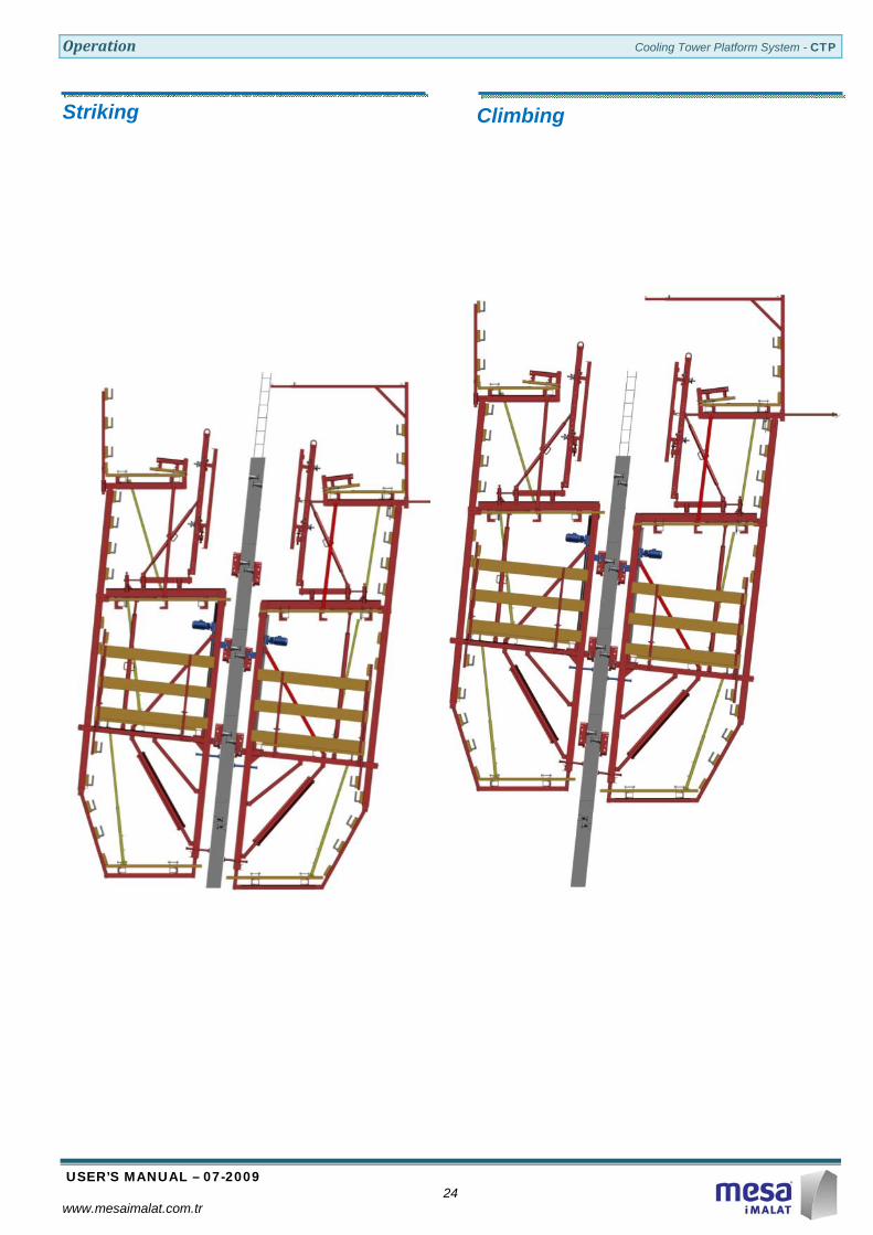
Striking
Climbing

Operation Cooling Tower Platform System - CTP
USER’S MANUAL – 07-2009 25
www.mesaimalat.com.tr
Concreting
Rebar Working
Operation Cooling Tower Platform System - CTP
USER’S MANUAL – 07-2009 26
www.mesaimalat.com.tr
FORMWORK and CLIMBING OPERATION

Operation Cooling Tower Platform System - CTP
USER’S MANUAL – 07-2009 27
www.mesaimalat.com.tr
Anchoring Positioning the Conical Anchor
Assemble the Conical Anchor, Anchor Tie and Anchor Tie-nut which will be located inside the concrete.
Mount Conical Anchor Assembly on
Formwork with the Hexagon Keybolt M30x50 through pre-drilled hole on the Formwork.
Mounting the Suspension Shoe
By unscrewing the Hexagon Keybolt M30x50 on the formwork, Suspension Shoe will be ready to mount on the concrete.
Use the Hexagon Keybolt M30x80 to mount the Suspension Shoe on the concrete.
Observe that the top point of the key-hole on the Suspension Shoe should be in contact with the the Hexagon Keybolt M30x80.
Adjust the height of the Suspension Shoe by
the Adjusting Screw located at the bottom on it.
Tighten the Hexagon Keybolt M30x80 to fix the Suspension Shoe.
1
2

Operation Cooling Tower Platform System - CTP
USER’S MANUAL – 07-2009 28
www.mesaimalat.com.tr
Removing the Suspension Shoe
Loosen the Hexagon Keybolt M30x80 on the Suspension Shoe.
Hold up the Suspension Shoe until the large hole of the key-hole is on the same level with the Hexagon Keybolt M30x80, then pull back the Suspension Shoe.
Removing the Conical Anchor
Insert the Conical Anchor Spanner and, unscrew the Conical Anchor.
Observe that Anchor Tie and Anchor Tie-nut are embedded in concrete.
Keep safe all spare parts ( i.e.tie-rods, wing nuts and plates, locking clips, Hexagon Keybolts etc.) against any damage.
1
2
1
2
3

Operation Cooling Tower Platform System - CTP
USER’S MANUAL – 07-2009 29
www.mesaimalat.com.tr
Dismantling of the Formwork
Unscrew the Hexagon Keybolt M30x50 of Conical Anchor on both Inside and Outside Formworks.
Unscrew the Wing Nut and Plate of Tie-Rods
of Outside Formworks.
Pull the Tie-Rods and Wing Nuts from Inside Formworks towards the inside.
Remove the Locking Clips on joints of Inside
and Outside Formworks located on Connection Platforms.
Dismantling of Formworks starts on the CTP-No.1 and continues in ascending order.
Keep safe all spare parts ( i.e.tie-rods, Wing Nuts and Plates, Locking Clips, Hexagon Keybolts etc.) against any damage.
3
1
2

Operation Cooling Tower Platform System - CTP
USER’S MANUAL – 07-2009 30
www.mesaimalat.com.tr
Do not forget to fold back the hinged parts of the Reinforcement Platforms.
Unscrew the Locking Screw of the Formwork Carriage.
Separate the Formwork from the Concrete and
withdraw back. Lock the Formwork Carriage by using the Locking Screw.
Unscrew the Conical Anchors from the concrete.
Prepare the formworks for next concreting.
After the removal of formworks, the Lower Suspension Shoes should be dismantled.
1
23

Operation Cooling Tower Platform System - CTP
USER’S MANUAL – 07-2009 31
www.mesaimalat.com.tr
Climbing of the Main Frame
Check shop drawings, assembly drawings, instruction documentations or any other information supplied by MESA.
Preperation
Mount the Motor-Gear Box Assembly to the
Jack-Rack Bar Assembly by using the Connection Bracket given.
Hangs down the Cable-Remote Control Unit
of the Motor-Gear Box to the Climbing Platform.
Check the voltage existing in the Electric box on the CTP.
Plug the electrical cable of the Motor-Gear Box to the plug connector located on the Electric Box of the CTP.
Be sure two Safety Wing Nuts on the Stability-Bars located in both sides of the Jack-Rack Bar are in proper positions.
Be sure that the Safety Pins of both Lower Suspension Shoes of the Main Frame are removed.
Screw the Fixing Jacks of Lifting Frame to fix it with the concrete.
Unscrew the Fixing Jacks of Main Frame to
loose it from the concrete (at least 30 mm).
Be sure two Lower Suspension Shoes are to be removed.
1 2 3

Operation Cooling Tower Platform System - CTP
USER’S MANUAL – 07-2009 32
www.mesaimalat.com.tr
Starting of Raising
Release the Lock-Switch (coloured in red) on
the Cable-Remote Control Unit to allow the electrical operation. Press UP buton on the Cable-Remote Control Unit to allow raising of Main Frame.
Do not forget to lock the Lock-Switch on the Cable-Remote Control Unit after each operation against unauthorised usage to keep away from accidental events.
Remove the Safety Pin on top of the Suspension Hook on the Main Frame.
Raise the CTP approximately 30 cm. Check this dimension by observing the Marks on Stability-Bars.
Safety Wing Nuts on the Stability Bars are raised.
Lower the Safety Wing Nuts on the Stability
Bars by screwing them up to the Lifting Frame upper profile.
During climbing operations, always observe the connections between Stable and Connection Platforms.
Dismount the Motor-Gear Box Assembly from the Jack-Rack Bar.
Repeat each steps starting from preperation for
respective CTP Units.
After completing first 30 cm. climbing of the whole ring, repeat each steps starting from preperation for respective CTP Units.
After 5 climbing cycles, check all connections between Stable and Connection platforms and locations of Safety Wing Nuts.
1 2
1 2 3
1 2
1 2 3

Operation Cooling Tower Platform System - CTP
USER’S MANUAL – 07-2009 33
www.mesaimalat.com.tr
Ending of Raising
When coming to the last 30 cm of raising
operation, pass upward the Suspension Hook on the Main Frame from the Top Suspension Shoe approximately 3 cm.
Insert the Bearing Pins to the bottom bearing
hole on the Top Suspension Shoes in both sides.
Press DOWN button on the Cable-Remote
Control Unit to lower the Main Platform until the Suspension Hooks on it connects to the Bearing Pins.
Lower the Safety Wing Nuts on the Stability
Bars by screwing them up to the Lifting Frame upper profile.
Insert the Safety Pins to the bottom safety
hole on the Top Suspension Shoes in both sides.
Do not use damaged, distorted or curved Pins and replace them by new ones.
Screw down the Safety Wing Nuts on the Stability Bars of Main Frame towards the Lifting Frame upper profile.
Screw the Fixing Jacks of Main Frame
towards the concrete in order to provide the stability of the Main Frame.
Fasten the Lock-Switch (coloured in red) on
the Cable-Remote Control Unit to lock the electrical operation.
1 2 3
1 2
Operation Cooling Tower Platform System - CTP
USER’S MANUAL – 07-2009 34
www.mesaimalat.com.tr
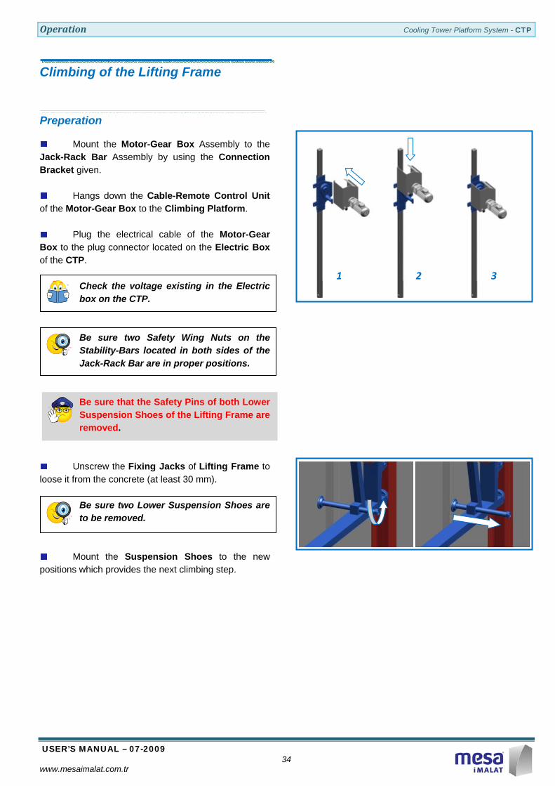
Climbing of the Lifting Frame
Preperation
Mount the Motor-Gear Box Assembly to the Jack-Rack Bar Assembly by using the Connection Bracket given.
Hangs down the Cable-Remote Control Unit
of the Motor-Gear Box to the Climbing Platform.
Plug the electrical cable of the Motor-Gear Box to the plug connector located on the Electric Box of the CTP.
Check the voltage existing in the Electric box on the CTP.
Be sure two Safety Wing Nuts on the Stability-Bars located in both sides of the Jack-Rack Bar are in proper positions.
Be sure that the Safety Pins of both Lower Suspension Shoes of the Lifting Frame are removed.
Unscrew the Fixing Jacks of Lifting Frame to loose it from the concrete (at least 30 mm).
Be sure two Lower Suspension Shoes are to be removed.
Mount the Suspension Shoes to the new positions which provides the next climbing step.
1 2 3

Operation Cooling Tower Platform System - CTP
USER’S MANUAL – 07-2009 35
www.mesaimalat.com.tr
Starting of Raising
Do not forget to lock the Lock-Switch on the Cable-Remote Control Unit after each operation against unauthorised usage to keep away from accidental events.
Remove the Safety Pins of the Lifting Frame on Suspension Shoe.
Release the Lock-Switch (coloured in red) on the Cable-Remote Control Unit to allow the electrical operation and press DOWN button on the Cable-Remote Control Unit to allow raising of Lifting Frame.
Raise the Lifting Frame by one casting level.
Safety Wing Nuts on the Stability Bars are raised.
1 2 3
1 2

Operation Cooling Tower Platform System - CTP
USER’S MANUAL – 07-2009 36
www.mesaimalat.com.tr
Ending of Raising
When coming to the end of raising operation,
pass upward the Suspension Hook on the Lifting Frame from the Top Suspension Shoe approximately 3 cm.
Insert the Bearing Pins to the top bearing hole
on the Suspension Shoes in both sides.
Press UP button on the Cable-Remote
Control Unit to lower the Lifting Platform until the Suspension Hooks on it connects to the Bearing Pins.
Lower the Safety Wing Nuts on the Stability
Bars by screwing them up to the Lifting Frame Upper Profile.
Insert the Safety Pins to the top safety pin
holes on the Suspension Shoes in both sides.
Do not use damaged, distorted or curved Pins and replace them by new ones.
Screw down the Safety Wing Nuts on the Stability Bars of Main Frame towards the Lifting Frame Upper Profile.
Screw the Fixing Jacks of Lifting Frame
towards the concrete in order to provide the stability of the Lifting Frame.
Fasten the Lock-Switch (coloured in red) on
the Cable-Remote Control Unit to lock the electrical operation.
Dismount the Motor-Gear Box Assembly from
the Jack-Rack Bar.
Repeat each steps starting from preperation for respective CTP Units.
1 2
1 2 3

Operation Cooling Tower Platform System - CTP
USER’S MANUAL – 07-2009 37
www.mesaimalat.com.tr
Finalising of Climbing Operation
Horizontality of Platforms
Adjust the flatness and horizontality of platforms by using Adjusting Prop located on the Climbing Platform.
During climbing operations, always observe the connections between Stable and Connection Platforms.
Dismantling of Electro-Mechanic Devices
Dismantle the Motor-Gear Box Assembly and
keep it safe and clear for the next climbing operations.
Make periodical maintenance of Motor-Gear Box and Jack-Rack Bar Assemblies against lean, damage of cables, rust and mositure.
1 2 3

Operation Cooling Tower Platform System - CTP
USER’S MANUAL – 07-2009 38
www.mesaimalat.com.tr
Setting up of the Formwork
Adjustment of Inside Formwork
Unscrew the Locking Screw of the Inside
Formwork Carriage.
Push the Inside Formwork towards the concrete.
Press the Inside Formworks onto the concrete.
Height of concrete contacted with the Formwork is the difference between the Formwork Height and the Concrete Height cast in one concreting phase.
Screw the Locking Screw of the Inside Formwork Carriage.
If necessary, add or remove 100mm Fixed
Fillers between the main panels and Main Panels on Inside Formworks.
Adjust the position of the Adjusting Panels according to the diameter of the Concrete level of Cooling Tower currently poured.
1
3
2
INSIDE
INSIDE
1 2 3 4

Operation Cooling Tower Platform System - CTP
USER’S MANUAL – 07-2009 39
www.mesaimalat.com.tr
Mount Conical Anchors on Inside Formworks with the Hexagon Keybolts M30x50.
Fasten the Inside Formworks with Locking
Clips.
Make level adjustment with the jack under the vertical stiffeners.
Adjust the gradient of Inside Formworks with the Inclined Props mounted on the Formwork Carriage and the formwork itself.
Loosen parts (i.e. Anchor Ties and Anchor Tie-Nuts) should be mounted on the Conical Anchors.
1 2 3

Operation Cooling Tower Platform System - CTP
USER’S MANUAL – 07-2009 40
www.mesaimalat.com.tr
Adjustment of Outside Formwork
Add or remove 100mm Fixed Fillers between
the Main Panels and Sliding Panels on Outside Formworks.
Push the Tie-Rods through the bottom tie-rod holes on the Inside Formworks.
Slip the Tube Spacers or Cone Spacers onto
the Tie-Rods.
Mount Conical Anchors on Outside Formworks with the Hexagon Keybolts M30x50. .
1 2 3 4

Operation Cooling Tower Platform System - CTP
USER’S MANUAL – 07-2009 41
www.mesaimalat.com.tr
Unscrew the Locking Screw of the Outside Formwork Carriage.
Push the Outside Formwork towards the concrete.
Push the bottom Tie-Rods through the hole on the Outside Formworks.
Fasten the Outside Formworks with Locking Clips.
Do not forget to fold back the hinged parts of the Reinforcement Platforms both on Inside and Outside CTP’s.
1
3
2
OUTSIDE
OUTSIDE
1 2 3

Operation Cooling Tower Platform System - CTP
USER’S MANUAL – 07-2009 42
www.mesaimalat.com.tr
Aligning
Insert the Top Tie-Rods through Inside Formworks.
Put Distance Spacers into the Top Tie-Rods and tighten them loosely.
Screw the Wing-Nuts of Outside Formworks on Tie-Rods.
Make level adjustment and inside diameter control of the construction by using The Total Station located on the ground.
Align the Inside Formworks in accordance to Measuring Plates.
Use Total Station Indicators positioned on Interior CTP.
Use Inclined Props both of Inside and Outside Formworks for aligining.
Tighten the Wing-Nuts of bottom Tie-Rods on Inside Formworks.
Screw the Locking Screw of the Outside Formwork Carriage. Reinforcement
Make sure that the reinforcement does not close the Tie-Rod holes and coincide with Conical Anchors.

Operation Cooling Tower Platform System - CTP
USER’S MANUAL – 07-2009 43
www.mesaimalat.com.tr
CONCRETING of FIRST THREE RINGS

Operation Cooling Tower Platform System - CTP
USER’S MANUAL – 07-2009 44
www.mesaimalat.com.tr
First Ring
After erecting the starting Platforms and base concreting, set up Inside Formworks and align them.
Set up Outside Formworks, insert up and down Tie-Rods and tigthen them.
After concreting, dismantle Inside and Outside
Formworks, and stock them on the ground. Second Ring
Mount Suspension Shoes on the Anchors embedded in the concrete of first ring.
Hang on the Initial Brackets which will support Inside and Outside Formworks.
Connect Formworks on Initial Brackets.
Set up Inside and Outside Formworks, align them properly and insert up and down Tie-Rods and tigthen them.

Operation Cooling Tower Platform System - CTP
USER’S MANUAL – 07-2009 45
www.mesaimalat.com.tr
After concreting, pull back Inside and Outside Formworks. Third Ring
Mount Suspension Shoes on the Anchors embedded in the concrete of second ring.
Lift the Initial Brackets carrying the Formworks to one level up.
Set up Inside and Outside Formworks, align them properly and insert up and down Tie-Rods and tigthen them.
After concreting, pull back Inside and Outside Formworks.
Remove Formworks and transfer Initial Brackets and Formworks to the Ground.

General Maintenance Cooling Tower Platform System - CTP
USER’S MANUAL – 07-2009 46
www.mesaimalat.com.tr
General Inspection and Maintenance Periodical Inspections before Concreting
Verify horizontal and vertical positions of the
Conical Anchors.
Verify Anchor-Ties and Anchor Tie-Nuts left into the concrete.
Verify that back side of the Suspension Shoe touches the concrete.
Periodical Inspections before and after Climbing
Verify that the Suspension Hooks of Main and Lifting Frames are correct in shape.
Clean up the Rack Bars after each use.
Verify that Jack-Rack Bar Assembly and Motor-Gear Box assembly are correctly working together.
Verify that All Platforms are free from unnecessary loadings.
Verify that concrete surface is free from any material as tie-rod, reinforcement bars etc. which can hinder the climbing process.
Remember that, when CTP system is lifting up, all its weight is carried by the electro-mechanic lifting system.
Verify that the Guiding Wheels working in between Lifting Frames and Main Frames are in good condition without causing any damage on the steel constructions.
Verify that Safety Pins are always correctly fitted.
Verify electric supply and electric cables. Immediately Rechange the cables if damaged.
Periodical Maintenance
Authorised person responsible from CTP System must know and carry out all the points explained in this manual and make them applied by concerned persons.
The temperature and wind speeds must be observed permanently and working operation must be arranged according to the limits indicated in this manual.
Interval of Periodical Inspections must not exceed one month. User could shorten this period.
Rack Bars and Jacks must be lubricated all times. Check grease levels.
All weldings on Steel Construction must be observed periodically.
Working operation must be stopped immediately if any welding shows cracking and manufacturer must be informed without delay.
All bolts of the construction must be checked, fastened or replaced if needed.
All platform and guardrail timber beams must be checked periodically.
At least, one person must be entrusted with the checking of the Electrical Distribution Boxes.

General Maintenance Cooling Tower Platform System - CTP
USER’S MANUAL – 07-2009 47
www.mesaimalat.com.tr
Electrical Circuit Diagram

General Maintenance Cooling Tower Platform System - CTP
USER’S MANUAL – 07-2009 48
www.mesaimalat.com.tr
Wiring Scheme
WIRING SCHEME
1 mm2M
ON
O P
HAS
ELA
MP
YELL
OW
LAM
P
SW
ITCH
GRE
EN L
AMP
SWIT
CH
2,5 mm2
4 m
m2
4 m
m2
4 m
m2
4 m
m2
4 m
m2
4 m
m2
4 m
m2 4
mm
2
1 m
m2
4 m
m2
4 mm2
1 mm2
2,5
mm
2
1 m
m2
2,5 mm2
2,5 mm2
2,5 mm2
4 mm2
4 mm2
4 mm2
1 m
m2
LIM
IT S
WIC
H
A1
A2
CO
NTA
CTO
RB
OBB
IN
4 mm2
CO
VER
SWIC
H
TH
REE
PH
ASE
C16
C16
30
mA
3RT
1026
-1A
C3x
25 C
B
RS
TN
ELI
NE
IN
6T3
2T1
4T2
5L3
3L2
1L1

Notes Cooling Tower Platform System - CTP
USER’S MANUAL – 07-2009 www.mesaimalat.com.tr