
Plastic collapse load of crown-hinged steel circular arches : a theoretical method · PDF...
21
Plastic collapse load of crown-hinged steel circular arches : a theoretical method Spoorenberg, R.C.; Snijder, H.H.; Hoenderkamp, J.C.D. Published in: Advances in Structural Engineering DOI: 10.1260/1369-4332.16.4.721 Published: 01/01/2013 Document Version Publisher’s PDF, also known as Version of Record (includes final page, issue and volume numbers) Please check the document version of this publication: • A submitted manuscript is the author's version of the article upon submission and before peer-review. There can be important differences between the submitted version and the official published version of record. People interested in the research are advised to contact the author for the final version of the publication, or visit the DOI to the publisher's website. • The final author version and the galley proof are versions of the publication after peer review. • The final published version features the final layout of the paper including the volume, issue and page numbers. Link to publication Citation for published version (APA): Spoorenberg, R. C., Snijder, H. H., & Hoenderkamp, J. C. D. (2013). Plastic collapse load of crown-hinged steel circular arches : a theoretical method. Advances in Structural Engineering, 16(4), 721-740. DOI: 10.1260/1369- 4332.16.4.721 General rights Copyright and moral rights for the publications made accessible in the public portal are retained by the authors and/or other copyright owners and it is a condition of accessing publications that users recognise and abide by the legal requirements associated with these rights. • Users may download and print one copy of any publication from the public portal for the purpose of private study or research. • You may not further distribute the material or use it for any profit-making activity or commercial gain • You may freely distribute the URL identifying the publication in the public portal ? Take down policy If you believe that this document breaches copyright please contact us providing details, and we will remove access to the work immediately and investigate your claim. Download date: 12. May. 2018
-
Upload
duongthien -
Category
Documents
-
view
215 -
download
0
Transcript of Plastic collapse load of crown-hinged steel circular arches : a theoretical method · PDF...
Plastic collapse load of crown-hinged steel circulararches : a theoretical methodSpoorenberg, R.C.; Snijder, H.H.; Hoenderkamp, J.C.D.
Published in:Advances in Structural Engineering
DOI:10.1260/1369-4332.16.4.721
Published: 01/01/2013
Document VersionPublisher’s PDF, also known as Version of Record (includes final page, issue and volume numbers)
Please check the document version of this publication:
• A submitted manuscript is the author's version of the article upon submission and before peer-review. There can be important differencesbetween the submitted version and the official published version of record. People interested in the research are advised to contact theauthor for the final version of the publication, or visit the DOI to the publisher's website.• The final author version and the galley proof are versions of the publication after peer review.• The final published version features the final layout of the paper including the volume, issue and page numbers.
Link to publication
Citation for published version (APA):Spoorenberg, R. C., Snijder, H. H., & Hoenderkamp, J. C. D. (2013). Plastic collapse load of crown-hinged steelcircular arches : a theoretical method. Advances in Structural Engineering, 16(4), 721-740. DOI: 10.1260/1369-4332.16.4.721
General rightsCopyright and moral rights for the publications made accessible in the public portal are retained by the authors and/or other copyright ownersand it is a condition of accessing publications that users recognise and abide by the legal requirements associated with these rights.
• Users may download and print one copy of any publication from the public portal for the purpose of private study or research. • You may not further distribute the material or use it for any profit-making activity or commercial gain • You may freely distribute the URL identifying the publication in the public portal ?
Take down policyIf you believe that this document breaches copyright please contact us providing details, and we will remove access to the work immediatelyand investigate your claim.
Download date: 12. May. 2018
1. INTRODUCTIONIn many cases arches are built by joining two separatecurvilinear segments together at the crown, therebyreducing the arch size to meet transport requirementsand to create a statically determinate structure which isinsensitive to detrimental effects of foundationsettlements. The joint location is often significantlyweaker compared to the arch-rib, and thereforeidealized as a hinge. This crown hinge is able to transfershear forces and normal forces but is unable to resistbending moments, leading to free rotation of the archsegments about the hinge axis. The introduction of ahinge at the crown in an arch without a crown hinge orso-called “continuous” arch [Figure 1(a)] reduces it to acrown-hinged arch [Figure 1(b)] and this will affect itsstructural response to loading. The stiffness andstrength capacity of the arch will be reduced with theintroduction of a hinge at the crown. Provided the archhas sufficient resistance to in-plane buckling [Figure 1(c)]
Advances in Structural Engineering Vol. 16 No. 4 2013 721
Plastic Collapse Load of Crown-Hinged Steel Circular
Arches: A Theoretical Method
R.C. Spoorenberg*, H.H. Snijder and J.C.D. Hoenderkamp
Eindhoven University of Technology, Faculty of the Built Environment, The Netherlands
(Received: 6 December 2011; Received revised form: 14 June 2012; Accepted: 20 November 2012)
Abstract: For construction purposes and to avoid detrimental influences of foundationsettlements arches are not always made from a single arch-rib but are built byconnecting two curvilinear elements at the crown with a hinge. These arches are alsoknown as crown-hinged arches. This paper presents an analytical procedure toapproximate the plastic collapse load of circular crown-hinged steel arches. Thedevelopment of the analytical method employs the lower- and upper bound theorem ofplastic theory and the kinematic admissibility requirements. The influence of normalforces on the plastic moment capacity of the steel section is taken into account. Theplastic collapse load is obtained by an iterative method as there is a non-linearrelationship between the acting loads and the reduction of the plastic moment capacitydue to normal forces. Through a comparison with earlier studies and finite elementanalyses, it is concluded that the proposed iterative method gives good results.
Key words: steel crown-hinged arch, plastic collapse load, yield contour, kinematic admissibility, iterative method,plastic theory.
and out-of-plane buckling [Figure 1(d)], the failure loadof a crown-hinged arch can be approximated by theplastic collapse load [Figure 1(e)]. The in-plane elasticbuckling behavior of one-hinged and three-hingedarches received large attention by Timoshenko and Gere(1961). Equations for elastic buckling loads werepresented for parabolic arches under a verticaluniformly distributed load and circular arches subject toradially uniformly distributed loads, causing uniformcompression in the arch-rib prior to buckling. Theinfluence of bridge-deck stiffness on the in-planebuckling of three-hinged arches as applied in bridge-design was published by Hayashi (1971).
To the knowledge of the authors the onlyinvestigation into the plastic collapse load of crown-hinged arches was published by Yamasaki and Ishikawa(1968). They used differential equations to determinethe elastic-plastic response of crown-hinged arches fromthe onset of loading up to plastic collapse. In addition
*Corresponding author. Email address: [email protected]; Fax: +31-40-245-0328; Tel: +31-40-247-2948.

confined to pin-supported arches made from I-sections,for which a simplified yield contour was used.Expanding these limit analyses to include crown-hingedarches with other yield contours and support conditionswould require a significant extension of their work.
In this paper, a different approach to study theplastic collapse of crown-hinged circular steel I-section arches is presented. An analytical approach isused, which is applicable to a wide range of archgeometries and cross-sections. It allows a change inthe structural parameters without changing theunderlying equilibrium equations. Pin-supportedcircular arches with a hinge at the crown subjected toeither a central point load or a uniformly distributedload are analyzed [Figure 2(a)] in addition to fixedcircular arches with a hinge at the crown subjected toa central point load [Figure 2(b)]. Pin-supportedarches with a hinge at the crown and fixed arches witha hinge at the crown are referred to as three-hingedand one-hinged arches respectively, throughout thispaper. All arches have a constant cross-section alongthe developed arch-length.
2. METHODOLOGY FOR PLASTIC COLLAPSEANALYSIS
Plastic collapse analyses are frequently used to obtainthe plastic collapse load of beams and frames, wherebya lower bound theorem or an upper bound theorem isused. In the present study, both theorems arecombined. As part of the lower bound theorem, abending moment distribution and normal forcedistribution are assumed in the arch-rib that are inequilibrium with the external loads and for which theyield criterion is not violated. A mechanism condition
722 Advances in Structural Engineering Vol. 16 No. 4 2013
Plastic Collapse Load of Crown-Hinged Steel Circular Arches: A Theoretical Method
limit load analyses were conducted. It was found thatthe introduction of a crown hinge in the arch reduces theplastic collapse load significantly. The study was
(e) In-plane plastic capacity
Plastic hinge
F
(c) In-plane instability
F
(d) Out-of-plane instability
F F
(a) "Continuous" arch
F
(b) Crown-hinged arch
F
Hinge
Figure 1. Arch lay-out, instability and plastic collapse load
Central point load
(a) Three-hinged arch
(b) One-hinged arch
F
qF
Uniformly distributed load
Central point load
Figure 2. Load cases and support conditions investigated

is assumed with a sufficient number of plastic hinges,which reduces the arch to a plastic collapse mechanismas part of the upper bound theorem. Both theorems arecombined by adjusting the bending moment andnormal force distributions such that they satisfy themechanism condition, without violating the yieldcontour. This yields an exact value for the plasticcollapse load. The deformation mode must be checkedto be in agreement with the kinematic admissibility ofthe collapse mode.
2.1. Plastic Hinge Locations
A three-hinged and a one-hinged arch are staticallydeterminate and statically indeterminate to the seconddegree, respectively. From a redundancy point of view athree-hinged arch has no redundancy and a one-hingedarch has two redundancies. Reducing a three-hinged archto a mechanism requires the formation of one plastichinge [Figure 3(a)] whereas three plastic hinges arenecessary to form a plastic mechanism in a one-hingedarch [Figure 3(b)]. Possible plastic hinge locations arebetween the crown and the support or at the support.When an arch is loaded and supported symmetrically,plastic hinges can emerge simultaneously on both sidesof the crown, rendering two plastic hinges in excess ofthe arch redundancy instead of one. The crown-hingelocation is denoted by number “1”. The plastic hinges arenumbered according to their location on the arch-rib. Theplastic hinge forming between the crown and the supportis denoted by number “2”. The plastic hinge forming atthe support is denoted by number “3”. The formation oftwo plastic hinges in a three-hinged arch [Figure 3(c)] or
four plastic hinges in a one-hinged arch [Figure 3(d)] cantake place when the arch is mostly subject to bending. Inthis case it fails by a so-called flexural mechanism, e.g.for arches with a large rise-to-span ratio (f/L) [Figure3(e)]. However, for shallow arches with small rise-to-span ratios, compressive action is predominant, causingthe arch to fail by a so-called compressive mechanism,Bakker et al. (2008) [Figure 3(f)]. By examining thekinematic admissibility of the collapse mode it can bechecked whether the correct mechanism has beenselected.
2.2. Assumptions
The proposed analyses are based on 1st order plastictheory: equilibrium is defined in the undeformedshape of the arch. The moment-curvature relationshipof the cross-section is assumed to be rigid plastic,which is a simplification of the true moment-curvaturebehavior [Figure 4(a)]. Hence it is assumed that nodeformations take place prior to the attainment of theplastic collapse load. The cross-section of the arch isable to sustain sufficient rotations under plasticmoment without failing by local buckling, allowingredistribution of forces in the arch-rib during thecourse of loading. Only sections belonging to class 1according to Eurocode 3 EN 1993-1-1 (2004) willtherefore suffice. The influence of shear force on theplastic moment capacity and normal force capacity isnot taken into account. Sagging moments and hoggingmoments are denoted as positive and negative,respectively. Compressive forces are taken asnegative and tensile forces are taken as positive.
Advances in Structural Engineering Vol. 16 No. 4 2013 723
R.C. Spoorenberg, H.H. Snijder and J.C.D. Hoenderkamp
Crown hingePlastic hinge
Collapse mode
2 23 3
2 2Bending moments FFF
F
f f
LL
(c) 2 plastic hinges inthree-hinged arch
(d) 4 plastic hingesone-hinged arch
(e) Flexural mechanismfor central load
(f) Compressivemechanism for central load
(b) 3 plastic hinged in one-hinged arch
F
(a) 1 plastic hinge in three-hinged arch
Crown hinge Plastic hinge
Collapse mode
F
Figure 3. Arch configurations, collapse mechanisms and possible hinge locations

2.3. Yield Contour and Normality Rule
The yield contour quantifies the influence of the normalforce on the plastic moment capacity of a steel section.Depending on the shape of the cross-section, many yieldcontours are available in the literature to approximatethe moment-normal force relationship. The presentstudy is confined to wide flange sections bent abouttheir major axis for which the yield contour ψ is asfollows:
In which Mpl is the full plastic moment, M is thebending moment, Npl is the squash load of the crosssection and N is the axial force. This yield contour is agenerally accepted engineering approximation of thetrue curve [Figure 4(b)] and has seen widespreadapplication in the design of steel structures: Trahairet al. (1997) and Trahair et al. (2007). As the yieldcontour is symmetric with respect to the coordinateaxes, only one quadrant is shown. The normality rulerelates the finite rotation (ϕ), contraction (δ), curvature(κ) and axial strain (ε) to each other for any combinationof moment and normal force.
(2)
dM
dN
N
M
M
N= −
∂ ∂∂ ∂
= − = ± = ±ψψ
εκ
δϕ
/
/
.
.
1 18
0 15
pl
pl
for 33 1≤ ≤N
Npl
(1)
ψ
ψ
= − = ≤ ≤
= −
M
M
N
N
N
N
pl pl
pl
1 0 0 0 0 153
1 18 1 0
. .
. .
for
− =
≤ ≤
M
M
N
N
pl
plfor
0
0 153 1 0. .
(3)
The lower sign corresponds to the case where themoments and normal forces have opposite sign (e.g.sagging moments and compressive forces). The uppersign corresponds to the case where the bendingmoments and normal force in the plastic hinge have thesame sign (e.g hogging moment and compressive force).
3. ANALYSES3.1. Three-Hinged Arch with Central Point Load
The symmetric conditions of a three-hinged arch with acentral point load allow the investigation to beperformed on only a half arch. The half arch geometryis expressed by the subtended angle γ and the archradius R. The angular coordinate system θ is used todescribe the normal force distribution, bending momentdistribution and plastic hinge location, for which: 0 ≤ θ≤ γ. The crown hinge is located at the angle: θ1 = θ = 0.This hinge is annotated as no. 1. The plastic hinge withreduced plastic moment capacity Mpl2;red is located at anangle θ2 in between crown and support. The reduction ofthe plastic moment capacity in the plastic hinges isaccording to Eqn 1.
The reaction forces depicted in Figure 5(a) can becomputed by considering equilibrium:
(4)
The reaction force at the support equals thecompressive force at the crown, as no other horizontalforces act on the arch:
(5)R N NBH = =( ) = −θ 0 1
R F R RFR
RBV AH BH= = =−( )
12
12
1
sin
cos
γγ
dM
dN
N
N= ≤ ≤0 0 0 153for
pl.
724 Advances in Structural Engineering Vol. 16 No. 4 2013
Plastic Collapse Load of Crown-Hinged Steel Circular Arches: A Theoretical Method
(a) Cross-sectional behavior
Rigid plastic
Elastic-plasticbehavior cross-section
0
0
1.0
κ
M/M
pl
(c) Plastic hinge in I-section
M MN N
δ
ϕ
(b) Plastic capacity cross-section
κ
ε0
0
1.0
1.0
M/M
pl
Eq.(1)
True interaction
0.153 N/Npl
Figure 4. Moment-normal force interaction
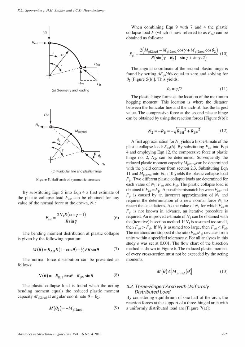
By substituting Eqn 5 into Eqn 4 a first estimate ofthe plastic collapse load Fest can be obtained for anyvalue of the normal force at the crown, N1:
(6)
The bending moment distribution at plastic collapseis given by the following equation:
(7)
The normal force distribution can be presented asfollows:
(8)
The plastic collapse load is found when the actingbending moment equals the reduced plastic momentcapacity Mpl2;red at angular coordinate θ = θ2:
(9)M Mθ2 2( ) = − pl red;
N R Rθ θ θ( ) = − −BH BVcos sin
M R R FRθ θ θ( ) = −( ) −AH 1 12cos sin
FN R
Rest =−( )2 11 cos
sin
γγ
When combining Eqn 9 with 7 and 4 the plasticcollapse load F (which is now referred to as Fpl) can beobtained as follows:
(10)
The angular coordinate of the second plastic hinge isfound by setting dFpl/dθ2 equal to zero and solving forθ2 [Figure 5(b)]. This yields:
θ2 = γ /2 (11)
The plastic hinge forms at the location of the maximumhogging moment. This location is where the distancebetween the funicular line and the arch-rib has the largestvalue. The compressive force at the second plastic hingecan be obtained by using the reaction forces [Figure 5(b)]:
(12)
A first approximation for N1 yields a first estimate of theplastic collapse load: Fest(6). By substituting Fest into Eqn4 and employing Eqn 12, the compressive force at plastichinge no. 2, N2, can be determined. Subsequently thereduced plastic moment capacity Mpl2;red can be determinedwith the yield contour from section 2.3. Substituting Eqn11 and Mpl2;red into Eqn 10 yields the plastic collapse loadFpl. Two different plastic collapse loads are determined foreach value of N1: Fest and Fpl. The plastic collapse load isobtained if Fest = Fpl. A possible mismatch between Fest andFpl is caused by an incorrect approximation of N1 andrequires the determination of a new normal force N1 torestart the calculations. As the value of N1 for which Fest =Fpl is not known in advance, an iterative procedure isrequired. An improved estimate of N1 can be obtained withthe (iterative) bisection method. If N1 is assumed too small,then Fest > Fpl. If N1 is assumed too large, then Fest < Fpl.The iterations are stopped if the ratio Fest /Fpl deviates fromunity within a specified tolerance e. For all analyses in thisstudy e was set at 0.001. The flow chart of the bisectionmethod is shown in Figure 6. The reduced plastic momentof every cross-section must not be exceeded by the actingmoments:
(13)
3.2. Three-Hinged Arch with Uniformly
Distributed Load
By considering equilibrium of one half of the arch, thereaction forces at the support of a three-hinged arch witha uniformly distributed load are [Figure 7(a)]:
M Mθ θ( ) ≤ ( )pl red;
N R R R22 2= − = − +B BH BV
FM M M
Rplpl red pl red pl red=
− +( )2 2 2 2 2; ; ;cos cosγ θ
ssin sin sinγ θ γ γ−( ) − +( )2 2
Advances in Structural Engineering Vol. 16 No. 4 2013 725
R.C. Spoorenberg, H.H. Snijder and J.C.D. Hoenderkamp
(b) Funicular line and plastic hinge
F/2
θ
θ2
Mpl2;red
N1
RB
γ
(a) Geometry and loading
F/2
R
RBH
RBV RB
γ
θ
RAH
2
Figure 5. Half-arch of symmetric structure
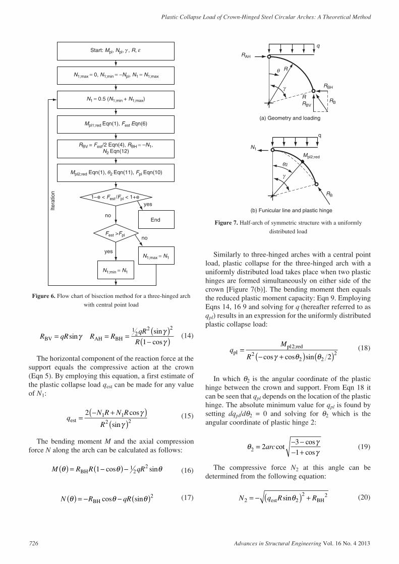
Similarly to three-hinged arches with a central pointload, plastic collapse for the three-hinged arch with auniformly distributed load takes place when two plastichinges are formed simultaneously on either side of thecrown [Figure 7(b)]. The bending moment then equalsthe reduced plastic moment capacity: Eqn 9. EmployingEqns 14, 16 9 and solving for q (hereafter referred to asqpl) results in an expression for the uniformly distributedplastic collapse load:
(18)
In which θ2 is the angular coordinate of the plastichinge between the crown and support. From Eqn 18 itcan be seen that qpl depends on the location of the plastichinge. The absolute minimum value for qpl is found bysetting dqpl/dθ2 = 0 and solving for θ2 which is theangular coordinate of plastic hinge 2:
(19)
The compressive force N2 at this angle can bedetermined from the following equation:
(20)N q R R2 22 2= − ( ) +est BHsinθ
θ γγ2 2
3
1=
− −− +
arccotcos
cos
qM
Rpl
pl red=− +( ) ( )
2
22 2
22
;
cos cos sinγ θ θ
726 Advances in Structural Engineering Vol. 16 No. 4 2013
Plastic Collapse Load of Crown-Hinged Steel Circular Arches: A Theoretical Method
Start: Mpl, Npl, , R,
N1;max = 0, N1;min = −Npl, N1 = N1;max
Mpl1;red Eqn(1), Fest Eqn(6)
Mpl2;red Eqn(1), 2 Eqn(11), Fpl Eqn(10)
1–e < Fest /Fpl < 1+e
N1 = 0.5 (N1;min + N1;max)
End
N1;max = N1
yes
Fest >Fpl
N1;min = N1
no
yes
no
Itera
tion
RBV = Fest/2 Eqn(4), RBH = –N1,N2 Eqn(12)
γ ε
θ
Figure 6. Flow chart of bisection method for a three-hinged arch
with central point load
(a) Geometry and loading
(b) Funicular line and plastic hinge
N1
RB
Mpl2;red
q
2
γ
RAH
R
RBRBV
RBH
q
γ
θ
θ
R
Figure 7. Half-arch of symmetric structure with a uniformly
distributed load
(14)
The horizontal component of the reaction force at thesupport equals the compressive action at the crown(Eqn 5). By employing this equation, a first estimate ofthe plastic collapse load qest can be made for any valueof N1:
(15)
The bending moment M and the axial compressionforce N along the arch can be calculated as follows:
(16)
(17)N R qRθ θ θ( ) = − − ( )BH cos sin 2
M R R qRθ θ θ( ) = −( ) −BH 1 12
2cos sin
qN R N R
Rest =
− +( )( )
2 1 12 2
cos
sin
γγ
R qR R RqR
RBV AH BH= = = ( )−( )sin
sin
cosγ
γγ
12
2 2
1

Any value of N1 will yield two different plasticcollapse loads: qest and qpl. A first estimate for N1 willproduce a value of the plastic collapse load qest usingEqn 15. Subsequently the reaction forces at the support,RBV and RBH are determined with Eqn 14, employingqest. From the reaction forces the compressive force N2
at plastic hinge 2 can be obtained with Eqn 20.Subsequently the reduced plastic moment capacity canbe determined by employing N2 in the yield contouraccording to Eqn 1. With θ2 from Eqn 19 and thereduced plastic moment capacity Mpl2;red, the plasticcollapse load qpl can be obtained from Eqn 18. Amismatch between qest and qpl is caused by a crudeestimate for N1 and hence a new value for N1 needs to bedetermined. An improved estimate of N1 is made withthe (iterative) bisection method (Figure 8). If N1 isassumed too small, then qest > qpl. If N1 is assumed toolarge, then qest < qpl. When the ratio qest /qpl is within thespecified tolerance limit e the iterations are stopped. Asa final check the plasticity condition given in Eqn 13must be verified.
3.3. One-Hinged Arch with Central Point Load
For a one-hinged arch it is assumed that the first plastichinge develops at the support. This hinge is replaced bya reacting moment Mpl3;red which imposes a reactantmoment distribution on the arch-rib. The one-hingedarch fails by a vertical mechanism [Figure 3(d)], i.e. thesecond plastic hinge develops simultaneously at angleθ2 in the left and right parts of the arch. Thus, a total offour plastic hinges in the arch structure are formed.
The reaction forces at the supports can be determinedby considering the free-body diagram [Figure 9(a)]:
(21)R F R RFR M
RBV AH BH= = =+
−( )21
12 3sin
cos
γγ
pl ;red
Advances in Structural Engineering Vol. 16 No. 4 2013 727
R.C. Spoorenberg, H.H. Snijder and J.C.D. Hoenderkamp
Start: Mpl, Npl, γ, R, ε
N1;max = 0, N1;min = –Npl, N1 = N1;max
Mpl1;red Eqn(1), qest Eqn(15)
Mpl2;red Eqn(1), 2 Eqn(19), qpl Eqn(18)
1–e < qest/qpl < 1+e
N1 = 0.5 (N1;min + N1;max)
End
N1;max = N1
yes
qest > qpl
N1;min = N1
no
yes
no
Itera
tion
RBV(qest) Eqn(14), RBH = –N1,N2 Eqn(20)
θ
Figure 8. Flow chart of bisection method for a three-hinged arch
with a uniformly distributed load
(a) Geometry and loading
(b) Funicular line and plastic hinges
(c) Force composition at support
N1
N3
Mpl3;red
Mpl2;red
γ
F/2
RB
Funicular line Arch-rib
N3
γγ −
F/2
V3
RB
RBH
Mpl3;red
RAH
F/2
R
RBRBV
RBHγ
θ
2θ
2θ
2θ
2θ
Figure 9. Half-arch geometry of symmetric structure and reaction
force at support

The angle at which the second plastic hinge is formedcan be computed as follows [Figure 9(b)]:
(22)
From this the compressive action at the support N3
[Figure 9(c)] can be determined:
(23)
In the previous analyses the compressive force at thecrown, N1, was selected as the pivotal variable in thederivation of subsequent equilibrium equations.However, for the one-hinged arch with a central pointload N1 is not feasible, and therefore recourse was takento the compressive force at the support, N3 to derive theequilibrium equations. Substituting Eqn 21 into Eqn 22and combining with Eqn 23 gives an equation for theplastic collapse load Fest (replacing F) for a firstestimate of N3:
NF
3 222
= − −( )cossin
γ θθ
θ2 2= ( )arctan F RBH
where:
C1 = Mpl3;red − N3R (25)
With N3 the reduced plastic moment Mpl3;red is obtainedfrom the yield contour given in section 2.3. The bendingmoment distribution and compressive forces along thearch-rib are given by the following equations:
(26)
(27)
Utilizing Eqn 26 and Eqn 21 for substitution into Eqn 9yields the plastic collapse load F (hereafter is referred to asFpl) based on the plastic moment capacity Mpl2;red and theangular coordinate of the second plastic hinge, θ2:
(28)
The angular coordinate of the second plastic hinge isfound by setting dFpl /dθ2 equal to zero and solving for θ2:
where:
C2 = Mpl2;red + Mpl3;red (30)
With a first approximation for N3, the plastic collapseload Fest can be estimated with Eqn 24 and the reducedplastic moment at the support Mpl3;red according to Eqn 1.With Fest the reaction forces RBH and RBV can becalculated using Eqn 21, which in turn are used toevaluate the compressive force at the second plastichinge N2 with Eqn 12. The reduced plastic moment
(29)θ2
22 2
=
− − −
arc
pl2;red pl2;red pl3;red pl3
sec
M M M M ;;red
pl2;red
pl
2
242 0 5
(+ ) ( )cos sin .M C
M
γ γ
33;red pl2;red
pl2;red
C M
M
240 5
4
−( ) ( )
+
cos sin .γ γ
332
2 120 5 0 5C cos . sin .γ γ( ) ( )
F
M M M
Mpl
pl2;red pl3;red pl2;red
pl3;=
+ −
× −
2(
cosγ rred cos )
sin sin sin
θ
γ γ θ θ2
2 2R − + −( ) +( )
N R Rθ θ θ( ) = − −BH BVcos sin
M M R R
FR
θ θ γ
γ θ
( ) = − −( )+ −
pl3;red BH cos cos
sin sin12 (( )
(24)
F
M N R
C
est
pl3;red
=
− +( ) + ( )
× (
2 1
8 0 5
3
12
/ sin
cos .
γ
γ )) ( ) −( )2 610 5 2
2
Sin . sin
sin
γ γ
γ
C
R
728 Advances in Structural Engineering Vol. 16 No. 4 2013
Plastic Collapse Load of Crown-Hinged Steel Circular Arches: A Theoretical Method
Start: Mpl, Npl, , R,
N3;max = 0, N3;min = –Npl, N3 = N3;max
Mpl3;red Eqn(1), Fest Eqn(24)
Mpl2;red Eqn(1), 2Eqn(29), Fpl Eqn(28)
1–e < Fest/Fpl < 1+e
N3 = 0.5 (N3;min + N3;max)
End
N3;max = N3
yes
Fest >Fpl
N3;min = N3
no
yes
no
Itera
tion
RBV = Fest/2 Eqn(21), RBH (Fest) Eqn(21),N2 Eqn(12)
F
θ
εγ
Figure 10. Flow chart of bisection method for a one-hinged arch
with central point load
capacity Mpl2;red can be obtained by substituting N2 intothe yield contour given by Eqn 1. Employing Mpl2;red andMpl3;red gives the location of the second plastic hinge θ2
with Eqn 29 which leads to Fpl from Eqn 28. Hence twodifferent plastic collapse loads are obtained: Fest and Fpl.Any mismatch between these values is caused by aninaccurate estimate of N3 and requires a newapproximation. The plastic collapse load is found for avalue of N3 for which Fest = Fpl. The (iterative) bisectionmethod is used to make an improved estimate N3. If N3
is assumed too small, then Fest > Fpl. If N3 is assumed toolarge, then Fest < Fpl. When the ratio Fest /Fpl is within aspecified tolerance value e the normal force at the onsetof plastic collapse is obtained and the iterations areterminated. The reduced plastic moment capacity atevery cross-section must not be exceeded by the appliedbending moment. This can be verified by Eqn 13.
3.4. Kinematic Admissibility
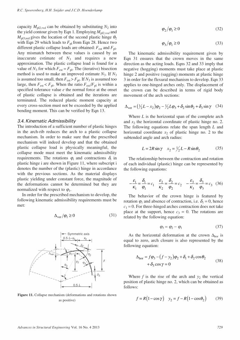
The introduction of a sufficient number of plastic hingesin the arch-rib reduces the arch to a plastic collapsemechanism. In order to make sure that the prescribedmechanism will indeed develop and that the obtainedplastic collapse load is physically meaningful, thecollapse mode must meet the kinematic admissibilityrequirements. The rotations ϕi and contractions δi inplastic hinge i are shown in Figure 11, where subscript idenotes the number of the (plastic) hinge in accordancewith the previous sections. As the material displaysplastic yielding under constant force, the magnitude ofthe deformations cannot be determined but they arenormalized with respect to ϕ1.
In order for the prescribed mechanism to develop, thefollowing kinematic admissibility requirements must bemet:
(31)∆ver ϕ1 0≥
(32)
(33)
The kinematic admissibility requirement given byEqn 31 ensures that the crown moves in the samedirection as the acting loads. Eqns 32 and 33 imply thatnegative (hogging) moments must take place at plastichinge 2 and positive (sagging) moments at plastic hinge3 in order for the flexural mechanism to develop. Eqn 33applies to one-hinged arches only. The displacement ofthe crown can be described in terms of rigid bodymovement of the arch sections:
(34)
Where L is the horizontal span of the complete archand x2 the horizontal coordinate of plastic hinge no. 2.The following equations relate the span length L andhorizontal coordinate x2 of plastic hinge no. 2 to thesubtended angle and arch radius:
(35)
The relationship between the contraction and rotationof each individual (plastic) hinge can be represented bythe following equations:
(36)
The behavior of the crown hinge is featured byrotation ϕ1 and absence of contraction, i.e. δ1 = 0, hencec1 = 0. For three-hinged arches contraction does not takeplace at the support, hence c3 = 0. The rotations arerelated by the following equation:
ϕ3 = ϕ2 − ϕ1 (37)
As the horizontal deformation at the crown ∆hor isequal to zero, arch closure is also represented by thefollowing equation:
(38)
Where f is the rise of the arch and y2 the verticalposition of plastic hinge no. 2, which can be obtained asfollows:
(39)f R y f R= −( ) = − −( )1 12 2cos cosγ θ
∆hor = − −( ) + +
+ =
f f yϕ ϕ δ δ θδ γ
3 2 2 1 2 2
3 0
cos
cos
− = = = = − = =εκ
δϕ
εκ
δϕ
εκ
δϕ
1
1
1
11
2
2
2
22
3
3
3
33c c c
L R x L R= = −2 21
2 2sin sinγ θ
∆ver = −( ) − + +12 2 2
12 3 2 2 3L x Lϕ ϕ δ θ δ γsin sin
ϕ ϕ3 1 0≥
ϕ ϕ2 1 0≥
Advances in Structural Engineering Vol. 16 No. 4 2013 729
R.C. Spoorenberg, H.H. Snijder and J.C.D. Hoenderkamp
Symmetric axis0.5 L–x2
0.5 L
θ2
γ
x2
y2 F
∆ver
2
3
ϕ2
ϕ3
1
δ
δ
ϕ
Figure 11. Collapse mechanism (deformations and rotations shown
as positive)
When employing Eqns 36, 37, 38 and c1 = 0, thekinematic admissibility requirement of Eqn 32 can berewritten as follows:
(40)
Eqn 33 can be rewritten by utilizing Eqns 37 and 40:
(41)
By employing Eqns 34, 36 and 40 the kinematicadmissibility requirement represented by Eqn 31 can berewritten as:
(42)
The kinematic admissibility of the plastic collapsemode can be checked by applying Eqns 40 and 42 forthree-hinged arches. For one-hinged arches Eqns 40, 41and 42 must be employed. These kinematicadmissibility requirements will be used later to checkthe validity of the calculated collapse loads.
4. COMPARISON WITH YAMASAKI ANDISHIKAWA
As part of a larger study on the elastic-plastic responseof steel arches, Yamasaki and Ishikawa (1968)investigated three-hinged arches with a central pointload and with a uniformly distributed load.
4.1. Yield Contour
The adopted yield contour was based on an idealizationof a moment-normal force interaction for an I-sectionbent about its major axis. To describe this yield contour,the ratio between the sectional area of the flanges andthe sectional area of the web was used:
(43)
where:Af is the area of the flangesAw is the area of the webh is the height of the cross-sectionb is the flange width of the cross-sectiontf is the flange thicknesstw is the web thicknessThe elastic moment capacity is given by:
(44)M t h f W fy w y el y= +( ) =1 3 62ρ
ρ = =A
A
bt
htf
w
f
w
2
∆ver
ϕγ
θ γ
θ1
3
2 2 2 3
2 2 2
=+
+ +
− +
f c
y c c
x c
cos
cos cos
sin ++( ) + −( ) ≥c L c31
2 3 0sin sinγ γ
ϕϕ
θθ γ
3
1
2 2 2
2 2 2 3
0=− −
+ +≥
f y c
y c c
cos
cos cos
ϕϕ
γθ γ
2
1
3
2 2 2 3
0=+
+ +≥
f c
y c c
cos
cos cos
where fy is the yield stress and Wel the elastic sectionmodulus. The squash load of the cross section waspresented as follows:
(45)
where A is the area of the cross-section. The yieldcontour was given by two equations:
where:
λ1 = (1 + ρ) / (1 + 3ρ) (47)
λ2 = (1 + ρ)2 / (1 + 3ρ) (48)
λ3 = (1 + 2ρ) / (1 + 3ρ) (49)
If ρ equals zero then the yield contour reduces to that ofa rectangular cross-section with height h and width tw. Asρ becomes larger the yield contour is that of aconventional wide flange section bent about its major axis.The yield contour of an open web section (wide flangesection without a web) with a linear moment-normal forceinteraction is found when ρ equals infinity (Figure 12).
The yield contour by Yamasaki and Ishikawa (1968) isnormalized with respect to the elastic moment capacity My
instead of the plastic moment capacity Mpl. It can be seenthat for a rectangular cross-section the plastic momentcapacity is 1.5 times larger than the elastic momentcapacity, i.e. the shape factor. The above yield contour isimplemented in the iterative method for comparison withthe results from Yamasaki and Ishikawa.
4.2. Comparison for Arches with a 120°
Subtended Angle
Three-hinged arches with a fixed subtended angle butwith different section height-to-span ratios (h/L) and ρ-values were analyzed by Yamasaki and Ishikawa(1968). Two loadcases were examined: a central pointload and a uniformly distributed load. The plasticcollapse load is normalized with respect to the squashload of the cross-section Npl for the central load at thecrown. For the uniformly distributed load, the plasticcollapse load is non-dimensionalized with respect to thespan length L and squash load. A full comparison ofnormalized collapse loads between the analyses ofYamasaki and Ishikawa (1968) and the authors is
(46)
M
M
N
N
N
N
M
y pl plif= −
<+
1 51
13 2
2
. λ λρ
MM
N
N
N
Ny plif= −
≥
+3 1
1
11λρpl
N t hf Afpl w y y= +( ) =1 ρ
730 Advances in Structural Engineering Vol. 16 No. 4 2013
Plastic Collapse Load of Crown-Hinged Steel Circular Arches: A Theoretical Method

presented in Table 1 and Table 2 for an arch carrying asingle force at the crown and a uniformly distributedload, respectively. A collapse load ratio is computed asFpl (Yamasaki and Ishikawa (1968))/Fpl (Iterativemethod) for arches with a central point load. For archeswith a uniformly distributed load the ratio is computedas qpl (Yamasaki and Ishikawa (1968))/qpl (Iterativemethod). In addition, the kinematic admissibilityrequirements are shown. It can be seen that the iterativemethod follows the results of Yamasaki and Ishikawa
quite closely and that the deformation mode satisfies thekinematic admissibility requirements.
4.3. Comparison for Arches with other
Subtended Angles
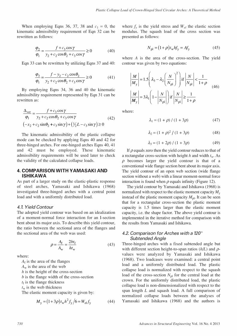
A similar comparison is made for three-hinged archeswith identical load cases presented in section 4.2 butwith other subtended angles. The h/L ratio and ρ-valueare fixed at 0.05 and 0, respectively. From Table 3 it canbe observed that the iterative method produces almost
Advances in Structural Engineering Vol. 16 No. 4 2013 731
R.C. Spoorenberg, H.H. Snijder and J.C.D. Hoenderkamp
Table 1. Comparison of normalized plastic collapse loads for three-hinged arches with central point load:
subtended angle 2γ = 120°
ρ = 0 ρ = 1
Iterative method Iterative method
Kinematic Kinematic
Y.I* Admissibility Y.I* Admissibility
h/L Fpl/Npl Fpl/Npl ∆ver/ϕ1 ϕ2/ϕ 1 Ratio Fpl/Npl Fpl/Npl ∆ver/ϕ1 ϕ2/ϕ1 Ratio
0.02 0.64 0.64 >0 >0 1.00 0.96 0.96 >0 >0 1.000.03 0.96 0.96 >0 >0 1.00 1.43 1.42 >0 >0 1.010.04 1.27 1.27 >0 >0 1.00 1.85 1.85 >0 >0 1.000.05 1.57 1.58 >0 >0 0.99 2.25 2.26 >0 >0 1.00
* Y.I. = Yamasaki and Ishikawa (1968)
Table 2. Comparison of normalized plastic collapse loads for three-hinged arches with uniformly distributed
load: subtended angle 2γ = 120°
ρ = 0 ρ = 1
Iterative method Iterative method
Kinematic Kinematic
Y.I* Admissibility Y.I* Admissibility
h/L qplL/Npl qplL/Npl ∆ver/ϕ1 ϕ2/ϕ1 Ratio qplL/Npl qplL/Npl ∆ver/ϕ1 ϕ2/ϕ1 Ratio
0.02 4.46 4.48 >0 >0 1.00 6.05 6.03 >0 >0 1.000.03 6.23 6.26 >0 >0 1.00 7.80 7.85 >0 >0 0.990.04 7.65 7.70 >0 >0 0.99 9.05 9.11 >0 >0 0.990.05 8.80 8.86 >0 >0 0.99 10.0 10.1 >0 >0 0.99
* Y.I. = Yamasaki and Ishikawa (1968)
Web
area Awtw tw tw = 0
= 0 = Af /Aw = 1 1.0N/Npl
M/M
y
ε
κ
=
Flange area Af
(a) Idealisation of cross-section (b) yield contour
Elastic limitation1.5
1.0
= 0 = 1
ρ =
h
ρ ρ ρ ρ
ρρ
∞
∞
Figure 12. Idealization of cross-section by Yamasaki and Ishikawa (1968)
identical plastic collapse loads as found by Yamasakiand Ishikawa (1968).
4.4. Different Arch Configurations
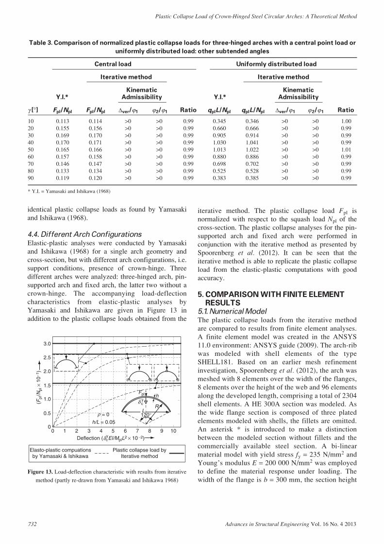
Elastic-plastic analyses were conducted by Yamasakiand Ishikawa (1968) for a single arch geometry andcross-section, but with different arch configurations, i.e.support conditions, presence of crown-hinge. Threedifferent arches were analyzed: three-hinged arch, pin-supported arch and fixed arch, the latter two without acrown-hinge. The accompanying load-deflectioncharacteristics from elastic-plastic analyses byYamasaki and Ishikawa are given in Figure 13 inaddition to the plastic collapse loads obtained from the
iterative method. The plastic collapse load Fpl isnormalized with respect to the squash load Npl of thecross-section. The plastic collapse analyses for the pin-supported arch and fixed arch were performed inconjunction with the iterative method as presented bySpoorenberg et al. (2012). It can be seen that theiterative method is able to replicate the plastic collapseload from the elastic-plastic computations with goodaccuracy.
5. COMPARISON WITH FINITE ELEMENTRESULTS
5.1. Numerical Model
The plastic collapse loads from the iterative methodare compared to results from finite element analyses.A finite element model was created in the ANSYS11.0 environment: ANSYS guide (2009). The arch-ribwas modeled with shell elements of the typeSHELL181. Based on an earlier mesh refinementinvestigation, Spoorenberg et al. (2012), the arch wasmeshed with 8 elements over the width of the flanges,8 elements over the height of the web and 96 elementsalong the developed length, comprising a total of 2304shell elements. A HE 300A section was modeled. Asthe wide flange section is composed of three platedelements modeled with shells, the fillets are omitted.An asterisk * is introduced to make a distinctionbetween the modeled section without fillets and thecommercially available steel section. A bi-linearmaterial model with yield stress fy = 235 N/mm2 andYoung’s modulus E = 200 000 N/mm2 was employedto define the material response under loading. Thewidth of the flange is b = 300 mm, the section height
732 Advances in Structural Engineering Vol. 16 No. 4 2013
Plastic Collapse Load of Crown-Hinged Steel Circular Arches: A Theoretical Method
3.0
2.5
2.0
1.5
1.0
0.5
Elasto-plastic compuationsby Yamasaki & Ishikawa
Plastic collapse load byIterative method
00 1 2 3 4 5 6 7 8
(Fpl
/Npl
× 1
0−1 )
9 10
h
RL120° = 0
h/L = 0.05
Fpl
cy
Deflection ( cyEI/MplL2 × 10 −2)
δ
ρ
δ
Figure 13. Load-deflection characteristic with results from iterative
method (partly re-drawn from Yamasaki and Ishikawa 1968)
Table 3. Comparison of normalized plastic collapse loads for three-hinged arches with a central point load or
uniformly distributed load: other subtended angles
Central load Uniformly distributed load
Iterative method Iterative method
Kinematic Kinematic
Y.I.* Admissibility Y.I.* Admissibility
γ [°] Fpl/Npl Fpl/Npl ∆ver/ϕ1 ϕ2/ϕ1 Ratio qplL/Npl qplL/Npl ∆ver/ϕ 1 ϕ2/ϕ 1 Ratio
10 0.113 0.114 >0 >0 0.99 0.345 0.346 >0 >0 1.0020 0.155 0.156 >0 >0 0.99 0.660 0.666 >0 >0 0.9930 0.169 0.170 >0 >0 0.99 0.905 0.914 >0 >0 0.9940 0.170 0.171 >0 >0 0.99 1.030 1.041 >0 >0 0.9950 0.165 0.166 >0 >0 0.99 1.013 1.022 >0 >0 1.0160 0.157 0.158 >0 >0 0.99 0.880 0.886 >0 >0 0.9970 0.146 0.147 >0 >0 0.99 0.698 0.702 >0 >0 0.9980 0.133 0.134 >0 >0 0.99 0.525 0.528 >0 >0 0.9990 0.119 0.120 >0 >0 0.99 0.383 0.385 >0 >0 0.99
* Y.I. = Yamasaki and Ishikawa (1968)

h = 290 mm, the flange thickness tf = 14 mm and theweb thickness tw = 8.5 mm.
5.1.1. Hinge modeling
The arch was modeled with two separate curvilinearsections jointed at the crown (Figure 14). The hinge atthe crown was modeled by a set of coupled degrees offreedom [Figure 15(a)]. In order to avoid high stressconcentrations MPC184 elements were applied over thecross-section on both sides of the hinge. Thetranslations in all three directions and rotations aboutthe x-axis and z-axis of the mid-height node of the leftsection were coupled to the equivalent node on the right
side. Only the rotations about the y-axis were notcoupled, allowing the desired hinge behavior duringloading to occur [Figure 15(b)]. It can be seen thatcontact between the upper flanges of the twocurvilinear segments is not modeled and the elementsmove ‘through’ each other.
5.1.2. Loading and boundary conditions
At the supports the arches were constrained againsttranslation in all three directions and rotations withrespect to the z-axis and x-axis (Figure 14). For one-hinged arches, rotations at the support about the y-axiswere constrained as well. Multipoint constraint elementswere applied over the cross-section at the support inorder to avoid high stress concentrations (Figure 16).Identical elements (MPC184) and element distributionas applied at the crown hinge were applied at thesupport. Loads were applied at the mid-height of thecross-section. The uniformly distributed load wasapplied in the numerical model by means of verticalpoint loads acting over the arch-rib.
5.1.3. Solution procedure and post-processing
A first order analysis was performed, taking intoaccount material non-linearities, but ignoring theinfluence of deformations on the equilibriumequations. The Newton-Raphson method was selectedto solve the non-linear equilibrium equations. Allanalyses were load-controlled. Equilibrium equationswere considered solved when the out-of-balance loadvector is less than 0.05% of the applied loading andwhen the out-of-balance displacement incrementvector is smaller than 0.05% of the displacementincrements. The load-deflection characteristics fromthe elastic-plastic computations are presented inFigure 17 for a HE 300A* arch with a developed
Advances in Structural Engineering Vol. 16 No. 4 2013 733
R.C. Spoorenberg, H.H. Snijder and J.C.D. Hoenderkamp
Left section FHinge
z = 0
x = 0
z = 0
x = 0
y
x
z
Right section
Rise
γ
R
In-plane pinned orclamped, out-of-
plane clamped andtorsional restraint
Span
ϕ
ϕ
ϕ
ϕ
Figure 14. Finite element model of three-hinged arch with central
point load at the crown
(a) Hinge prior to loading
(b) Hinge during arch deformation
MPC 184 over height of the web and widthof flanges on either side of the hinge
Coupled equations
y
x
z
y
x
Figure 15. Crown hinge rotation
Arch
y
MPC184 elementsover web height
MPC184 elementsalong flange width
Support
x
z
Figure 16. Detail of support
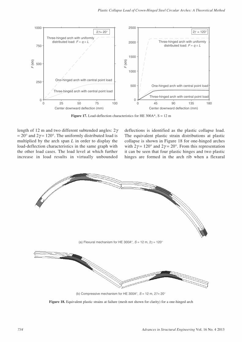
length of 12 m and two different subtended angles: 2γ= 20° and 2γ = 120°. The uniformly distributed load ismultiplied by the arch span L in order to display theload-deflection characteristics in the same graph withthe other load cases. The load level at which furtherincrease in load results in virtually unbounded
deflections is identified as the plastic collapse load.The equivalent plastic strain distributions at plasticcollapse is shown in Figure 18 for one-hinged archeswith 2γ = 120° and 2γ = 20°. From this representationit can be seen that four plastic hinges and two plastichinges are formed in the arch rib when a flexural
734 Advances in Structural Engineering Vol. 16 No. 4 2013
Plastic Collapse Load of Crown-Hinged Steel Circular Arches: A Theoretical Method
0
250
500
750
1000
0 25 50 75 100
F (
kN)
Center downward deflection (mm)
One-hinged arch with central point load
Three-hinged arch with uniformlydistributed load: F = q × L
2 = 20°
Three-hinged arch with central point load
γ
0
500
1000
1500
2000
2500
0 45 90 135 180
F (
kN)
Center downward deflection (mm)
One-hinged arch with central point load
Three-hinged arch with uniformlydistributed load: F = q × L
Three-hinged arch with central point load
2 = 120°γ
Figure 17. Load-deflection characteristics for HE 300A*, S = 12 m
(a) Flexural mechanism for HE 300A*, S = 12 m, 2γ = 120°
(b) Compressive mechanism for HE 300A*, S = 12 m, 2 = 20° γ
Figure 18. Equivalent plastic strains at failure (mesh not shown for clarity) for a one-hinged arch

mechanism or a compressive mechanism take place,respectively.
5.2. Three-Hinged Arch with Central Point Load
A full comparison between the results from non-linearfinite element analyses and the iterative method ispresented in Table 4. HE 300A* arches with adeveloped arch length S = 12 m and S = 16 m wereselected for a comparative study. It can be seen that theiterative method is able to replicate the results ofthe elastic-plastic computations with good accuracy.The ratio is evaluated as: Fpl (ANSYS)/Fpl (Iterativemethod). The kinematic admissibility requirements aremet for all investigated arches.
5.3. Three-Hinged Arch with Uniformly
Distributed Load
The same group of arches is selected to assess theperformance of the iterative method for a uniformly
distributed load. The comparison between the plasticcollapse load from elastic-plastic computations with thefinite element method and the iterative method ispresented in Table 5. It can be seen that the iterativemethod produces good approximations of the finiteelement results. The iterative method meets thekinematical requirements for all investigated arches.
5.4. One-Hinged Arch with Central Point Load
A comparison between the plastic collapse loadobtained from the iterative method and finite elementcomputation with ANSYS are shown in Table 6 for one-hinged arches with a central point load. It can be seenthat even for a number of arches for which onekinematic admissibility requirement is not met, theiterative method produces reasonably accurate values ofthe plastic collapse load. In these cases the arches areshallow and a compressive mechanism is determiningthe arch behavior, Figure 18(b).
Advances in Structural Engineering Vol. 16 No. 4 2013 735
R.C. Spoorenberg, H.H. Snijder and J.C.D. Hoenderkamp
Table 5. Comparison of plastic collapse loads (kN/m) of three-hinged HE 300A* arches with uniformly
distributed load
S = 12 m S = 16 m
Iterative method Iterative method
Kinematic Kinematic
ANSYS Admissibility ANSYS Admissibility
2γ [°] qpl qpl ∆ver/ϕ 1 ϕ 2/ϕ 1 Ratio qpl qpl ∆ver/ϕ 1 ϕ 2/ϕ 1 Ratio
10 36.3 36.3 >0 >0 1.00 27.2 27.2 >0 >0 1.0030 107 107 >0 >0 1.00 79.5 79.3 >0 >0 1.0060 188 185 >0 >0 1.02 132 132 >0 >0 1.0090 214 209 >0 >0 1.02 144 140 >0 >0 1.03120 201 196 >0 >0 1.03 130 124 >0 >0 1.05150 173 173 >0 >0 1.00 106 106 >0 >0 1.00180 153 153 >0 >0 1.00 89 91.5 >0 >0 0.97
Table 4. Comparison of plastic collapse loads (kN) of three-hinged HE 300A* arches with central point load
S = 12 m S = 16 m
Iterative method Iterative method
Kinematic Kinematic
ANSYS Admissibility ANSYS Admissibility
2γ [°] Fpl Fpl ∆ver/ϕ 1 ϕ2/ϕ 1 Ratio Fpl Fpl ∆ver/ϕ 1 ϕ2/ϕ1 Ratio
10 151 150 >0 >0 1.01 139 136 >0 >0 1.0230 272 278 >0 >0 0.98 229 234 >0 >0 0.9860 347 352 >0 >0 0.99 274 283 >0 >0 0.9790 371 384 >0 >0 0.97 291 303 >0 >0 0.96120 377 399 >0 >0 0.94 294 302 >0 >0 0.97150 371 397 >0 >0 0.93 291 298 >0 >0 0.98180 375 391 >0 >0 0.96 287 293 >0 >0 0.98
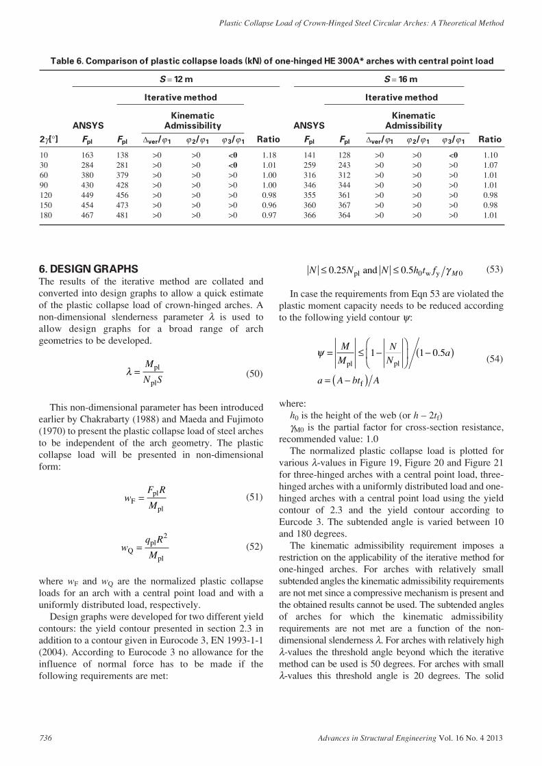
Table 6. Comparison of plastic collapse loads (kN) of one-hinged HE 300A* arches with central point load
S = 12 m S = 16 m
Iterative method Iterative method
Kinematic Kinematic
ANSYS Admissibility ANSYS Admissibility
2γ[°] Fpl Fpl ∆ver/ϕ 1 ϕ 2/ϕ 1 ϕ 3/ϕ 1 Ratio Fpl Fpl ∆ver/ϕ1 ϕ 2/ϕ 1 ϕ 3/ϕ 1 Ratio
10 163 138 >0 >0 <0 1.18 141 128 >0 >0 <0 1.1030 284 281 >0 >0 <0 1.01 259 243 >0 >0 >0 1.0760 380 379 >0 >0 >0 1.00 316 312 >0 >0 >0 1.0190 430 428 >0 >0 >0 1.00 346 344 >0 >0 >0 1.01120 449 456 >0 >0 >0 0.98 355 361 >0 >0 >0 0.98150 454 473 >0 >0 >0 0.96 360 367 >0 >0 >0 0.98180 467 481 >0 >0 >0 0.97 366 364 >0 >0 >0 1.01
6. DESIGN GRAPHSThe results of the iterative method are collated andconverted into design graphs to allow a quick estimateof the plastic collapse load of crown-hinged arches. Anon-dimensional slenderness parameter λ is used toallow design graphs for a broad range of archgeometries to be developed.
(50)
This non-dimensional parameter has been introducedearlier by Chakrabarty (1988) and Maeda and Fujimoto(1970) to present the plastic collapse load of steel archesto be independent of the arch geometry. The plasticcollapse load will be presented in non-dimensionalform:
(51)
(52)
where wF and wQ are the normalized plastic collapseloads for an arch with a central point load and with auniformly distributed load, respectively.
Design graphs were developed for two different yieldcontours: the yield contour presented in section 2.3 inaddition to a contour given in Eurocode 3, EN 1993-1-1(2004). According to Eurocode 3 no allowance for theinfluence of normal force has to be made if thefollowing requirements are met:
wq R
MQpl
pl=
2
wF R
MFpl
pl=
λ =M
N Spl
pl
(53)
In case the requirements from Eqn 53 are violated theplastic moment capacity needs to be reduced accordingto the following yield contour ψ:
(54)
where:h0 is the height of the web (or h – 2tf)γM0 is the partial factor for cross-section resistance,
recommended value: 1.0The normalized plastic collapse load is plotted for
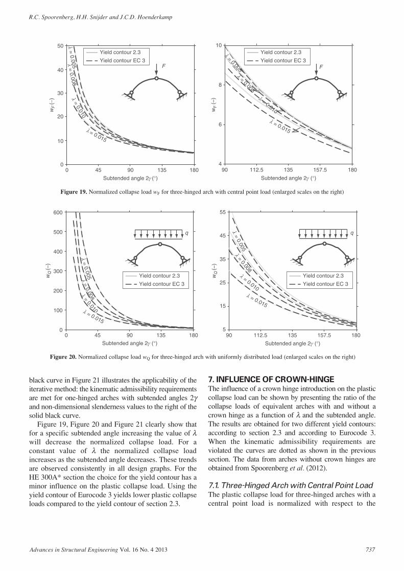
various λ-values in Figure 19, Figure 20 and Figure 21for three-hinged arches with a central point load, three-hinged arches with a uniformly distributed load and one-hinged arches with a central point load using the yieldcontour of 2.3 and the yield contour according toEurcode 3. The subtended angle is varied between 10and 180 degrees.
The kinematic admissibility requirement imposes arestriction on the applicability of the iterative method forone-hinged arches. For arches with relatively smallsubtended angles the kinematic admissibility requirementsare not met since a compressive mechanism is present andthe obtained results cannot be used. The subtended anglesof arches for which the kinematic admissibilityrequirements are not met are a function of the non-dimensional slenderness λ. For arches with relatively highλ-values the threshold angle beyond which the iterativemethod can be used is 50 degrees. For arches with smallλ-values this threshold angle is 20 degrees. The solid
ψ = ≤ −
−( )
= −( )
M
M
NN
a
a A bt A
pl pl
f
1 1 0 5.
N N N h t f≤ ≤0 25 0 5 0 0. .pl w yand γ M
736 Advances in Structural Engineering Vol. 16 No. 4 2013
Plastic Collapse Load of Crown-Hinged Steel Circular Arches: A Theoretical Method
black curve in Figure 21 illustrates the applicability of theiterative method: the kinematic admissibility requirementsare met for one-hinged arches with subtended angles 2γand non-dimensional slenderness values to the right of thesolid black curve.
Figure 19, Figure 20 and Figure 21 clearly show thatfor a specific subtended angle increasing the value of λwill decrease the normalized collapse load. For aconstant value of λ the normalized collapse loadincreases as the subtended angle decreases. These trendsare observed consistently in all design graphs. For theHE 300A* section the choice for the yield contour has aminor influence on the plastic collapse load. Using theyield contour of Eurocode 3 yields lower plastic collapseloads compared to the yield contour of section 2.3.
7. INFLUENCE OF CROWN-HINGEThe influence of a crown hinge introduction on the plasticcollapse load can be shown by presenting the ratio of thecollapse loads of equivalent arches with and without acrown hinge as a function of λ and the subtended angle.The results are obtained for two different yield contours:according to section 2.3 and according to Eurocode 3.When the kinematic admissibility requirements areviolated the curves are dotted as shown in the previoussection. The data from arches without crown hinges areobtained from Spoorenberg et al. (2012).
7.1. Three-Hinged Arch with Central Point Load
The plastic collapse load for three-hinged arches with acentral point load is normalized with respect to the
Advances in Structural Engineering Vol. 16 No. 4 2013 737
R.C. Spoorenberg, H.H. Snijder and J.C.D. Hoenderkamp
0
10
20
30
40
50
0 45 90 135 180
wF
(−)
Subtended angle 2γ (°)
F F
4
6
8
10
90 112.5 135 157.5 180
wF
(–)
Subtended angle 2γ (°)
Yield contour 2.3
Yield contour EC 3
λ = 0.010
λ = 0.010
λ = 0.005
λ = 0.005
λ = 0.008
λ = 0.008
= 0.015
= 0.015
Yield contour 2.3
Yield contour EC 3
λ
λ
Figure 19. Normalized collapse load wF for three-hinged arch with central point load (enlarged scales on the right)
λ = 0.010
λ = 0.010
λ = 0.005
λ = 0.005
λ = 0.008
λ = 0.008 λ = 0.015λ = 0.015
Yield contour 2.3
Yield contour EC 3
Yield contour 2.3
Yield contour EC 3
0
100
200
300
400
500
600
0 45 90 135 180
wQ
(–)
Subtended angle 2γ (°)
5
15
25
45
35
55
90 112.5 135
157.5 180
wQ
(–)
Subtended angle 2γ (°)
Figure 20. Normalized collapse load wQ for three-hinged arch with uniformly distributed load (enlarged scales on the right)

plastic collapse load obtained from equivalent archeswithout a crown hinge. The latter group is denoted astwo-hinged. Two hinged arches are also known as pin-supported arches. The collapse loads of three-hingedarches and two-hinged arches are abbreviated with “3 h”and “2 h”, respectively, as shown in Figure 22. It isclearly visible that the influence of introducing a hingeat the crown is most detrimental to arches with largesubtended angles and small λ values. The plasticcollapse load for a three-hinged arch is approximately60% of the plastic collapse load of its pin-supportedcounterpart when the subtended angle is 180°. It can beseen that the curves generally show a gradual decreasein percentages with increasing subtended angle. The
gradual change in percentage is disturbed for archeswith λ = 0.005 and λ = 0.008 and 70 ≤ 2γ ≤ 180. This isthe result of the employment of bi-linear yield contours.
7.2. Three-Hinged Arch with Uniformly
Distributed Load
The same comparison as for arches with a central loadat the crown is made for arches subjected to auniformly distributed load. The plastic collapse loadfor a three-hinged arch is normalized with respect tothe plastic collapse load of its pin-supportedequivalent. The plastic collapse loads of the lattergroup are obtained from Spoorenberg et al. (2012).The results are shown in Figure 23. It can be seen that
738 Advances in Structural Engineering Vol. 16 No. 4 2013
Plastic Collapse Load of Crown-Hinged Steel Circular Arches: A Theoretical Method
λ = 0.010
λ = 0.010
λ = 0.005
λ = 0.005
λ = 0.008
λ = 0.008
λ = 0.015
λ = 0.015
Yield contour 2.3
Yield contour EC 3
Yield contour 2.3
Yield contour EC 3
5
15
25
35
45
55
0 45 90 135 180
wF
(–)
Subtended angle 2γ (°)
5
7
11
9
F F
13
90 112.5 135 157.5 180
wF
(–)
Subtended angle 2γ (°)
Limit for kinematicadmissibility
Kinematic admissibilityrequirements are met
Kinematic admissibilityrequirements are violated
Figure 21. Normalized collapse load wF for one-hinged arch with central point load (enlarged scales on the right)
= 0.010
= 0.005
= 0.008
= 0.015
55
60
65
70
75
80
0 45 90
F F
135 180
Fpl
(3 h
)/F
pl(2
h)(
%)
Subtended angle 2γ (°)
Yield contour 2.3Yield contour EC 3
λ
λ
λ
λ
Figure 22. Ratio of central point loads for plastic collapse of three-
hinged arches and two-hinged arches
λ = 0.010
λ = 0.005
λ = 0.015
70
80
90
100
0 45 90 135 180
q
q
q pl(3
h)/
q pl(2
h)(
%)
Subtended angle 2γ (°)
Yield contour 2.3
Yield contour EC 3
λ = 0.008
Figure 23. Ratio of uniformly distributed loads for plastic collapse
of three-hinged arches and two-hinged arches

the effect of introducing a hinge at the crown for anarch under a uniformly distributed load is mostprofound for arches with relatively large subtendedangles and small λ-values. For semi-circular archesthe introduction of a hinge at the crown can result in adecrease in plastic collapse load of approximately30%. When comparing Figure 22 with Figure 23 it canbe seen that introducing a hinge at the crown in a pin-supported arch with a central point load is moredetrimental to the normalized plastic collapse loadthan for the same arches with a uniformly distributedload. This is partly attributed to the phenomenon thatthe presence of a hinge at the crown is moredetrimental for arches subject to predominantlybending actions, such as arches with a central pointload.
7.3. One-Hinged Arch with Central Point Load
Similarly to one hinged arches, the kinematicadmissibility for fixed or zero-hinged arches restrictsthe applicability of the iterative method to non-shallow arches. A comparison is made between one-hinged arches and their zero-hinged equivalentswhere the kinematic admissibility requirements aremet for both arches. The one-hinged arch is denotedas “1 h” and the zero-hinged arch is denoted as “0 h”.In Figure 24 the plastic collapse load for one-hingedarches is normalized with respect to the plasticcollapse load from its zero-hinged equivalent. It canbe seen that the reduction in plastic collapse load dueto the presence of a crown hinge is most significantfor arches with large subtended angles and small λvalues.
8. DISCUSSION8.1. Change of Mechanism
From the preceding sections it was found that theiterative method produces accurate values of the plasticcollapse load for three-hinged arches with a centralpoint load, three-hinged arches with a uniformlydistributed load and one-hinged arches with a centralpoint load. For shallow one-hinged arches it was foundthat the iterative method produces less accurate results,which is attributed to an incorrect assumption of thecollapse mechanism as illustrated by the violation of thekinematic admissibility requirements. Shallow one-hinged arches fail by a compressive mechanism whilefor the iterative method a flexural mechanism isassumed. The threshold angle 2γ beyond which theadopted collapse mechanism meets the kinematicadmissibility requirements depends in one-hingedarches on the arch slenderness λ which varies between20 and 50 degrees.
8.2. Use of Different Yield Contours
In the theoretical analyses three different yield contoursfor a wide flange section bent about the major axis wereused: Eqn 1, Eqn 46 and Eqn 54. The iterative methodallows the use of different yield contours without re-deriving the equilibrium equations by simply replacingthe description of the yield contour. The suggestedmethod can be used for wide flange sections subjectmajor axis bending and compression for which yieldcontours are provided by others, e.g. Chen and Atsuta(1977), Horne (1979), Orbison et al. (1982) and Duanand Chen (1990).
The iterative method is also applicable to wide flangesections bent about their minor axis which have asignificantly different yield contour from wide flangesections bent about their major axis. Asymmetric yieldcontours such as proposed by Kitipornchai et al. (1991)can also be used in the presented method to find theplastic collapse load of arches made from T-, L- ormonosymmetric I-sections. In these cases a distinctionmust be made between the yield contours for hoggingmoments and sagging moments.
9. CONCLUSIONSThis paper presented an analytical approach to obtainthe plastic collapse load for three-hinged arches with acentral point load, three-hinged arches with a uniformlydistributed load and one-hinged arches with a centralpoint load. Three-hinged arches are pin-supportedarches with a hinge at the crown and one-hinged archesare fixed arches with a hinge at the crown. The lowerbound theorem, upper bound theorem and kinematicadmissibility requirements as part of plastic theory were
Advances in Structural Engineering Vol. 16 No. 4 2013 739
R.C. Spoorenberg, H.H. Snijder and J.C.D. Hoenderkamp
= 0.010 = 0.005
= 0.008
= 0.015
60
65
F F
70
75
80
0 45 90 135 180
Fpl
(1 h
)/F
pl(0
h)(%
)
Subtended angle 2γ (°)
Yield contour 2.3
Yield contour EC 3
Limit for kinematicadmissibility
Kinematic admissibilityrequirements are met
Kinematic admissibilityrequirements are violated
λ λ λ λ
Figure 24. Ratio of central point loads for plastic collapse of one-
hinged arches and zero-hinged arches
used for the analyses. The reduction of the plasticmoment capacity by normal force was taken intoaccount. Due to the presence of a non-linear relationshipbetween the acting loads and the reduction in plasticmoment capacity, it was found necessary to employiterative techniques to arrive at the plastic collapse load.
All analyses were limited to steel circular arches madefrom wide flange sections bent about their major axis.Earlier studies and finite element analyses were selectedfor a comparative study from which it was concludedthat the iterative method is able to approximate theplastic collapse load with good accuracy.
Design graphs were developed containing plasticcollapse loads obtained with the iterative method for awide range of arch geometries, enabling a quick estimateof the plastic collapse load without taking recourse to theiterative method or finite element analysis. The designgraphs were derived independently of the arch geometrythrough the introduction of a single arch slendernessparameter, allowing the plastic collapse loads to bepresented in non-dimensional form.
Plastic collapse loads of crown-hinged arches wereexpressed as a percentage of the plastic collapse load forequivalent arches without a crown hinge to show the netinfluence of the introduction of a hinge at the crown. Itwas found that the magnitude of the decrease in plasticcollapse load by introducing a crown hinge depends onthe type of loading, support conditions and archgeometry. For arches featured by predominantlycompressive action in the arch-rib, such as shallowarches and arches with a uniformly distributed load, theintroduction of a crown hinge will result in only a smallreduction of the plastic collapse load. A larger decreasewas observed for deep arches with a central point loadand predominant bending action in the arch-rib.
The presented iterative method can be applied tocrown-hinged arches with different yield contours andgeometries.
REFERENCESANSYS (2009). ANSYS Structural Analysis Guide, Release 11.0,
ANSYS Inc., Canonsburg, PA, USA.
Bakker, M.C.M., Spoorenberg, R.C., Snijder, H.H. and
Hoenderkamp, J.C.D. (2008). “In-plane plastic limit load of
steel circular arches, a lower bound limit analysis approach”,
Proceedings of the 5th European Conference on Steel and
Composite Structures (Eurosteel), Graz, Austria,
pp. 1831–1836.
Chakrabarty, J. (1988). Theory of Plasticity, McGraw-Hill, London,
UK.
Chen, W.F. and Atsuta, T. (1977). Theory of Beam-Columns, Vol.2,
Space Behavior and Design, McGraw-Hill, New York, USA.
Duan, L. and Chen, W.F. (1990). “A yield surface equation for
doubly symmetrical sections”, Engineering Structures, Vol. 12,
No. 2, pp. 114–119.
EN 1993-1-1 (2004). Eurocode 3. Design of Steel Structures,
General Rules and Rules for Buildings, CEN European
Committee for Standardization, Brussels, Belgium.
Hayashi, T. (1971). Handbook of Structural Stability, Corona
Publishing Company, Ltd., Tokyo, Japan.
Horne, M.R. (1979). Plastic Theory of Structures, Pergamon press,
Oxford, UK.
Kitipornchai, S., Zhu, K., Xiang, Y. and Al-Bermani, F.G.A.
(1991). “Single-equation yield surfaces for monosymmetric and
asymmetric sections”, Engineering Structures, Vol. 13, No. 4,
pp. 366–370.
Maeda, Y. and Fujimoto, K. (1970). “Study on calculation of plastic
collapse load of two-hinged arch”, Transactions of the Japan
Society of Civil Engineers, Vol. 174, No. 2, pp. 25–40.
Orbison, J.G., McGuire, W. and Abel, J.F. (1982). “Yield surface
applications in nonlinear steel frame analysis”, Computer Methods
in Applied Mechanics and Engineering, Vol. 33, No. 1–3,
pp. 557–573.
Spoorenberg, R.C., Snijder, H.H. and Hoenderkamp, J.C.D.
(2012). “A theoretical method for calculating the collapse load
of steel circular arches”, Engineering Structures, Vol. 38,
pp. 89–103.
Timoshenko, S.P. and Gere, J.M. (1961). Theory of Elastic Stability,
McGraw-Hill, Tokyo, Japan.
Trahair, N.S., Bradford, M.A., Nethercot, D.A. and Gardner, L.
(2007). The Behaviour and Design of Steel Structures to EC3, 4th
edition, Taylor & Francis Group, London, UK.
Trahair, N.S., Pi, Y.L., Clarke, M.J. and Papangelis, J.P. (1997).
“Plastic design of steel arches”, Advances in Structural
Engineering, Vol. 1, No. 1, pp. 1–9.
Yamasaki, T. and Ishikawa, N. (1968). “Elasto-plastic analysis of
circular arches”, Transactions of the Japan Society of Civil
Engineers, Vol. 158, No. 10, pp. 1–16.
740 Advances in Structural Engineering Vol. 16 No. 4 2013
Plastic Collapse Load of Crown-Hinged Steel Circular Arches: A Theoretical Method


![Q :) Select the determinate structure from the …...Q :) Select the determinate structure from the following. [DMRC 2020] (a): Fixed beams (b): Two-hinged arches (c): Continuous beams](https://static.fdocuments.in/doc/165x107/5f82eff1b791db6e8d76431e/q-select-the-determinate-structure-from-the-q-select-the-determinate-structure.jpg)

