Plante' IC First Charge Maintenance
23
- 1 - INSTALLATION AND COMMISSIONING PROCEDURE FOR EXIDE PLANTE’ TYPE STANDBY BATTERIES COMPLETE WITH FIRST CHARGE INSTRUCTIONS AND MAINTENANCE PRACTICE
Transcript of Plante' IC First Charge Maintenance

7/28/2019 Plante' IC First Charge Maintenance
http://slidepdf.com/reader/full/plante-ic-first-charge-maintenance 1/23
- 1 -
INSTALLATION AND COMMISSIONING PROCEDURE
FOR
EXIDE PLANTE’ TYPE
STANDBY BATTERIES
COMPLETE WITH FIRST CHARGE INSTRUCTIONS AND
MAINTENANCE PRACTICE

7/28/2019 Plante' IC First Charge Maintenance
http://slidepdf.com/reader/full/plante-ic-first-charge-maintenance 2/23
- 2 -
CAUTION :
In order to ensure safety, it is essential to operate and maintain your batteries inaccordance with the recommendations in this booklet.
a) ACID : Batteries contain dilute sulphuric acid which is poisonous andcorrosive. It can cause burns on contact with skin and eyes. If acid is spliton skin or clothing, wash plenty of clean water. If acid gets in to the eyeswash well with plenty of clean water and get IMMEDIATE MEDICAL ATTENTION.
b) GASES : Batteries can give off explosive gases. Keep sparks, flames andlighted cigarettes away from battery and battery room. Ensure connectionsare tight before switching on, using only insulated tools. Areas wherebatteries are kept or charged must be adequately ventilated.
c) ELECTRICITY : Use only insulated tools to make connections to a battery.Check the circuit to ensure it is safe before making a connection to thebattery. Before working on a battery, always remove personal metal effects,
such as rings, watches, bracelets, necklaces, etc.
ALWAYS PROTECT THE EYES.
7/28/2019 Plante' IC First Charge Maintenance
http://slidepdf.com/reader/full/plante-ic-first-charge-maintenance 3/23
- 3 -
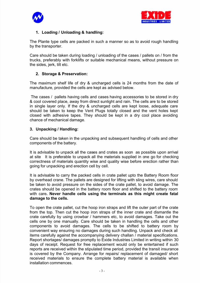
1. Loading / Unloading & handling:
The Plante type cells are packed in such a manner so as to avoid rough handlingby the transporter.
Care should be taken during loading / unloading of the cases / pallets on / from thetrucks, preferably with forklifts or suitable mechanical means, without pressure onthe sides, jerk, tilt etc.
2. Storage & Preservation:
The maximum shelf life of dry & uncharged cells is 24 months from the date of manufacture, provided the cells are kept as advised below.
The cases / pallets having cells and cases having accessories to be stored in dry& cool covered place, away from direct sunlight and rain. The cells are to be storedin single layer only. If the dry & uncharged cells are kept loose, adequate careshould be taken to keep the Vent Plugs totally closed and the vent holes keptclosed with adhesive tapes. They should be kept in a dry cool place avoidingchance of mechanical damage.
3. Unpacking / Handling:
Care should be taken in the unpacking and subsequent handling of cells and other components of the battery.
It is advisable to unpack all the cases and crates as soon as possible upon arrivalat site It is preferable to unpack all the materials supplied in one go for checkingcorrectness of materials quantity wise and quality wise before erection rather thangoing for unpacking and erection cell by cell.
It is advisable to carry the packed cells in crate pallet upto the Battery Room floor by overhead crane. The pallets are designed for lifting with sling wires, care shouldbe taken to avoid pressure on the sides of the crate pallet, to avoid damage. Thecrates should be opened in the battery room floor and shifted to the battery roomwith care. Never handle cells using the terminals as this might create fatal
damage to the cells.
To open the crate pallet, cut the hoop iron straps and lift the outer part of the cratefrom the top. Then cut the hoop iron straps of the inner crate and dismantle thecrate carefully by using crowbar / hammers etc, to avoid damages. Take out thecells one by one manually. Care should be taken in handling the cells and other components to avoid damages. The cells to be shifted to battery room byconvenient way ensuring no damages during such handling. Unpack and check allitems carefully against the accompanying delivery challan / material specifications.Report shortages/ damages promptly to Exide Industries Limited in writing within 30days of receipt. Request for free replacement would only be entertained if such
reports are received within the stipulated time period, provided the transit insuranceis covered by the Company. Arrange for repairs/ replacement of damaged/ shortreceived materials to ensure the complete battery material is available wheninstallation commences.

7/28/2019 Plante' IC First Charge Maintenance
http://slidepdf.com/reader/full/plante-ic-first-charge-maintenance 4/23
- 4 -
Store the cells (with the vent plugs screwed on firmly), and other accessories in adry cool, dust fee covered place.
3. Battery Room
The battery room should be well ventilated, clean and dry. A damp room isdangerous due to possible earth leakage from the battery. A notice should beexhibited in the battery room PROHIBITING SMOKING, ELECTRICAL OR ANYSPARKS AND USE OF NAKED FLAMES. The battery room should be well lit at alltimes of the day and night. Direct sunlight on the cells should be avoided. If it is notpossible to provide windows, good artificial light should be made available.
Although the battery shall have satisfactory performance between 50 C and 500 C,the most preferred operating temperature is between 200 C and 350 C. Higher temperatures shall decrease the life of the cells. Low temperatures, within theabove mentioned range, will reduce the capacity available but do not harm thebattery so far as the life is concerned. A wash basin is to be provided in the batteryroom, suitably placed for washing of accidental acid splash on eyes, body,garments etc., for the personnel working in the battery room. Any spillage of acid onthe floor is to be washed and neutralised, to avoid leakage path. It is advisable toprovide acid proof tiles on the floors and on the sides of the wall. Alternately acidproof paints to be provided which would require periodic renewal.
Proper exhaust fans to be provided to remove hydrogen gas from the battery roomduring boost charging. The ventilation system of the battery room has to be
designed accordingly. It is always better to pump in filtered cool air in the batteryrooms, having provision for natural exhaust, so that the battery room will be slightlyat higher pressure. The capacity requirement of the exhaust system depends onthe relative size of the battery room and the battery being accommodated in that.The exhaust calculation can be available from the Guaranteed Technical Particular of the specific installation. Site should demand a copy of the same from theprocurement authority.
Warning signs should be put on the walls indicating dangers of explosion in usingnaked flames for smoking inside the battery room.
The layout of the cells should be in line with the layout suggested by ExideIndustries Limited for the specific case. For any deviation and / or modificationplease contact Exide Industries Ltd.
4. Power Requirement:
A D. C. supply capable of delivering the constant current specified in the technicalspecifications will be required. The voltage required for initial charging is about 3times the number of cells in the battery bank, i.e. charger design to be 3 volts per cell. This is required to charge the battery banks e.g. 12 Amps DC ConstantCurrent up to 2.36 vpc & 6 Amps DC Constant Current (finishing rate) up to 2.75
vpc per 100 Ah C10 capacity of the battery bank.

7/28/2019 Plante' IC First Charge Maintenance
http://slidepdf.com/reader/full/plante-ic-first-charge-maintenance 5/23
- 5 -
5. Stands and Supports
Suitable Stands / Stillages are normally provided for the support of the cells and
are designed in a manner so that each cell will be easily accessible for inspection,maintenance etc.
Each installation shall have a dedicated relevant layout drawing of the battery. Theyshould be followed very carefully.
6. Charger:
The charging system must be capable of providing a steady voltage within 1%V.
Battery charger should be available at site for necessary initial charging of thebattery bank. This should be a constant current charger capable of supplying 12 Amps DC per 100 Ah C10 capacity of the battery to start with and 6 Amps DC per 100 Ah C10 capacity of the battery at the finishing stages of charging. The charger should be capable of providing 6% of the rated capacity of cells at 2.75 volts per cell during boost charging. The charger should also have facility for float charge ata voltage of 2.24 to 2.30 volts per cell. For equalizing charge, the charger shall becapable of supplying 3 Amps DC per 100 Ah C10 capacity of the battery.
Charger output or load induced current ripple can cause permanent damage
and a reduction in battery life. The RMS limit is 5% in amperes of the C10 capacity over the frequency range of 100 Hz to 360 Hz.
7. Polarity of Charging Leads
It is of utmost importance that the positive terminal of the battery is connected tothe positive lead of the charging source.
To ascertain the polarity of the charging leads connect a lamp in series and dip theend in a glass of slightly saline water. Switch on the supply. Fine bubbles of gas willbe give off from the negative lead
The lamp connected in series eliminates the dangers of accidental short circuits.
+
BULB
HYDROGENGAS

7/28/2019 Plante' IC First Charge Maintenance
http://slidepdf.com/reader/full/plante-ic-first-charge-maintenance 6/23
- 6 -
8. Acid / DM Water
i) The acid to be used in the battery for initial filling is battery gradeSulphuric Acid (H2SO4)of specific gravity 1.190 + 0.005, at 270 C,
conforming to IS: 266 - 1993. This is normally supplied with the battery. Acopy of IS:266 – 1993 is enclosed at the end of the manual.
ii) DM water should conform to IS:1069 - 1993 for topping up of cells. Acopy of IS:1069 enclosed.
iii) If the acid is obtained in concentrated form it is necessary to dilute it to1.190 Sp. Gr. The acid as well as the distilled water to be used for diluting the acid should conform to Indian Standard Institutionspecification IS: 266 – 1993 & IS: 1069 – 1993 respectively.
To dilute strong acid, the quantities required for mixing are given below:
For 100 litres Dilute Acid:
Initial Sp. Gravity Final Sp. GravityQuantity of water
in litresQuantity of acid
in litres
1.8401.8251.825
1.400
1.1901.4001.190
1.190
876686
56
184018
45
Note : When acid and water are mixed, there is a volume contraction, hencecolumns 3 & 4 do not total 100.
(iv) Caution:
1. All job to be done under supervision of authorised personnel only.
2. Clean vessels of hard rubber, plastics, porcelain or leadlined MS tanks/Wooden Boxes only should be used for storage & handling of acid & DM
water. Do not use metal vessels other than lead.
3. When working with acid or electrolytes always use protective goggles,rubber gloves and rubber apron.
4. Keep ready Bi-carbonate of Soda solution or 5% to 10% Ammonia solutionto take care of accidental spill / splash of acid on skin, eyes or garments.Remove garment immediately, neutralise spot with 5 to 10% ammonia or soda solution and wash thoroughly in water. On skin / eyes: flush with largequantities of water. Seek medical aid immediately.
5. NEVER ADD WATER TO ACID. IT WILL SPURT DANGEROUSLY. ALWAYS ADD ACID TO WATER. Add the acid in a thin stream, slowly,stirring the solution with a long glass rod or tube.

7/28/2019 Plante' IC First Charge Maintenance
http://slidepdf.com/reader/full/plante-ic-first-charge-maintenance 7/23
- 7 -
6. Smoking, Welding Arcs, Electrical Sparks and Open Flame should be strictlyprohibited in the battery room.
7. Only insulated tools should be used for live parts. Extreme care should betaken while handling of metallic parts within battery room to prevent their
accidental falling / touching of live parts and causing short circuit.
9. Temperature Correction
The specific gravity of the electrolyte varies with temperature. Any readingobserved on the hydrometer should therefore be corrected to 270 C ,as allthe specific gravity values indicated by us are at 270 C.The correction should therefore be made as follows :
For every 10 C above 270 C add 0.0007 to the specific gravity as read on thehydrometer. Similarly, for every 10 C below 270 C subtract 0.0007 from thespecific gravity as read from the hydrometer.
10. Installation
The following should be kept in mind while finalising the battery layout:
a) Easy access to the individual cells of the battery
b) Locating the take-offs for easy connection to the charging
equipment/load.
c) Keeping interior connections adjacent to walls for providing easysupport and keeping the passage in between clear. This is desirablefor easy access to the cells for allowing easy removal of cells for service attention , whenever required.
d) The positive end of the battery has to be connected to the positiveoutput of the charging equipment and negative end of the battery tothe negative of the charger .
e) The positive and negative „take-off ‟ of the battery should havesufficient space between them to avoid short circuits
(i) Place the cells in position on the Stand/ Stillage
Suitable insulators should also be used between the stand or Stillage andthe floor. Arrange cells to that the positive terminal lug of one cell adjoins thenegative terminal lug of the next throughout the battery. Use a woodenspacer to ensure even spacing out of cells.
For Seismic stands no Stand/ Stillage Insulator required as these are
grouted to the floor.

7/28/2019 Plante' IC First Charge Maintenance
http://slidepdf.com/reader/full/plante-ic-first-charge-maintenance 8/23
- 8 -
(ii) Fasteners (Bolt & Nuts)
Before connecting up, apply an even coating of petroleum jelly to the bolts,nuts, washers, connectors and terminal pillars. Cover the whole length of each terminal pillar with petroleum jelly and tighten the bolt connectors firmly
using two spanners, one on the bolt head and one on the nut.
Note particularly that the positive terminal of one cell is connected tonegative terminal of the next throughout the battery leaving the positiveterminal of the first cell and negative terminal of the last cell of the batterybank free for connection to the charging source. Finally, check again thatthe cells are connected in the correct sequence. Charging a cell of thewhole battery in the wrong direction will cause permanent damage.
(iii) Connect cells together :
When the cells are in position on the stands, connect them together Smear alittle petroleum jelly on the threads, bolting faces and in the bolt holes beforebolting up. If necessary, warm the petroleum jelly to ensure a thin evencoating. After bolting-up the cells smear petroleum jelly over the nut, bolthead and washers.
(iv) Cells in Rows
If the cells are arranged in more than one row, ensure that the positiveterminal lug of the end cell of one row is connected to the negative terminallug of the end cell of the other row. The connection between the two rows
may be made with the necessary length of copper of the size used betweenthe switchboard and the battery.
Each end of the copper rod/ cable (For YKP & YAP) is soldered into thesocket of the cable-ends provided or Crimped type Flexible cableconnectors, the ends of the latter being bolted on the terminal lugs of thebattery. For YHP range Copper bars/ Crimped Cable Ends for FlexibleConnectors are used.
Clean off any flux and bind the exposed end of the cable with self adhesivetape starting well back on the cable insulation and ending just at the lead
cable socket. All copper work should be painted with two coats of acidresisting enamel paint before the cells are filled with acid.
(v) Connecting to charger :
Connect positive terminal of the battery to the positive lead of chargingsource and negative terminal of the battery to negative lead of the chargingsource after identifying the polarity of the connections.
11. INITIAL FILLING-IN OF ELECTROLYTE
Sufficient quantity of battery-grade sulphuric acid and a little spare must beavailable at the site for the initial filling of the cells. The sulphuric acid shouldbe 1.190 +/- 0.005 Sp. Gr. (at 270 C ).

7/28/2019 Plante' IC First Charge Maintenance
http://slidepdf.com/reader/full/plante-ic-first-charge-maintenance 9/23
- 9 -
The approximate quantity of acid required per cell is given in the data sheet.The total quantity of acid required is obtained by multiplying the quantity per cell by the number of cells adding 10% to compensate for spillage.
The acid should be brought to equilibrium with the room temperature and of 1.190 Sp. Gravity. This acid should be carefully poured into the cells, up tothe maximum recommended level.
After filling in allow the cells to stand for a period of 8-12 hours. The plateswill absorb the electrolyte and the electrolyte level will drop. Restore theelectrolyte level at the end of this 8-12 hours period by adding more acid of 1.190 Sp. Gr.
After filling in all the cells, following are to be ensured prior tocommencement of initial charging:-
a) Checking of correct polarity of all the cells connected in the circuit.
b) Recording of individual cell voltage.
c) Recording the total battery voltage and comparison thereof with thesum total of individual cell voltage.
The battery is now ready for initial charging.
Initial charging must commence with in 24 hours of electrolyte filling & itis therefore essential to ensure that the charger is in proper workingcondition prior to electrolyte filling of the cells.
12. First Charge
(i) Charging Equipment
Ensure that the charging equipment is in order and is capable of deliveringthe specified current and voltage .
(ii) Connections – Polarity
Check and check again to ensure the cells are all connected in series and allfastenings and connections are tight.
Test polarity of the charging leads and connects the positive terminal of thebattery to the positive lead of the charger.
Caution : Charging a cell or battery in the wrong direction will ruin it.
(iii) First Charge
Commence charging not later than 24 hours after filling in the first cell withacid.
7/28/2019 Plante' IC First Charge Maintenance
http://slidepdf.com/reader/full/plante-ic-first-charge-maintenance 10/23
- 10 -
(iv) First Portion
The first portion of the charge should be given at any rate between thestarting/ finishing currents depending on the output of the charger. Reduce
charging current if temperature of electrolyte exceeds 50
0
C. Charging at thisrate shall continue till the potential of the battery rises to 2.36 volts per cell.
At the completion of this portion of the charge a rest of not more than 12hour and not less than 2 hours should be given.
(v) Second Portion
The second portion of the charge must be given at the finishing rate asmentioned in the relevant technical particulars. This stage to continue tilleither the signs of completion of charge as described in clause 12(vii) are
observed or the minimum Ah input required (as mentioned in the relevanttechnical particulars) is administered, whichever happens later .
This is very important for the life of the battery that the first charge beadministered very particularly so far as the Ah input is concerned .
(vi) Pilot Cells
As pilot cells select any one cell (except the end cell or regulating cell, if any)out of every 24 cells or part thereof.
Voltage and specific gravity readings from the pilot cells will indicate thestate of charge of the whole battery.
During charge take reading every 4 hourly reading up to 80% of chargefollowed by 1 hourly readings of :
a. Specific Gravityb. Voltagec. Temperature
(vii) Completion of charge
The signs of the completion of charge are as under
a) Specific Gravity : For some hours after starting the charge ,the specific gravity of the electrolyte will fall after which it willbegin to rise slowly and continue to rise throughout the chargeuntil finally it ceases to rise and remain constant. The chargeshould be continued until the specific gravities have attainedconstant figures for three (3) successive hourly readings in allcells.
b) Voltage : The cell Voltage at the beginning of the charge willbe a little over 2 volts and will rise during the charge finallyattaining a steady figure. The exact figure is not so importantas long as a Voltage around 2.65 Volts is attained. Typical
7/28/2019 Plante' IC First Charge Maintenance
http://slidepdf.com/reader/full/plante-ic-first-charge-maintenance 11/23
- 11 -
figures range from 2.65 – 2.75 Volts per cell at the finishingrate of charge , depending on the prevailing electrolytetemperature , which, when higher than 27 Deg C, tends todepress the voltage slightly from the ideal top of charge of 2.75V at 27 Deg C.
c) Gassing: The reduction of current during charge, asmentioned above, is to limit the amount of gassing, but at theend of the charge all the cells should gas freely and vigorously.If any cell fail to gas or is late in gassing or if it „s gravity islower than those of other cells, it should be closely examinedto find the cause. When found and corrected the chargeshould be continued until the cell is brought upto the fullycharged state like the others.
d) Colour of plates: The positive plates should assume a fullrich chocolate colour and negatives a smooth light grey whenfully charged. This can be observed in transparent containersonly.
When all these signs of completion of charge have been observed, and theminimum Ah input required (as mentioned in clause 12(v)) is administered,the charge should be terminated. About one hour afterwards, when the gasbubbles have cleared away, the specific gravity and temperature should berecorded.
During charging the electrolyte temperature of the cell should not exceed500C. Suspend the charge if the temperature reaches 500 C and resumecharging after the battery has cooled to about 450C. If necessary, slightlylower the recommended charging rate in case of very high ambienttemperatures. Where ambient temperatures are normally high, it isrecommended that charging be carried out during the night and suspendedduring the day. If necessary, use the finishing rate for the first portion of thecharge as well. When charging is suspended due to attainment of hightemperatures, such stoppages should be noted carefully and the durationshall be suitably extended to compensate for such stoppages.
(viii) Interruptions
The charging of the battery can be carried out either continuously or incycles of 8 hours charge and not more than 16 hours rest, till it is completed.
(ix) Electrolyte Level
Maintain the level throughout charging adding 1.190 Sp. Gr. Acid if necessary.
7/28/2019 Plante' IC First Charge Maintenance
http://slidepdf.com/reader/full/plante-ic-first-charge-maintenance 12/23
- 12 -
(x) Adjust Specific Gravity of Each Cell
If at the end of the first charge the specific gravity of the electrolyte exceeds1.205, withdraw some electrolyte and add pure water, continue the charge
so that the water and acid mix thoroughly.
If at the end of first charge the specific gravity of the electrolyte is below1.195 after both voltage and specific gravity have remained constant over 3consecutive hours, withdraw some electrolyte and add acid of 1.400 specificgravity continuing the charge in the meantime.
Never make an adjustment on cell which does not gas on charge.
Final specific gravity should be 1.200 +/- 0.005 in all the cells.
Adjust the levels of electrolyte in all cells by adding 1.200 specific gravityacid or by withdrawing excess electrolyte, as required.
(xi) Final Readings/ Record Book
After correcting specific gravity and electrolyte levels, start a record book for the whole life of the battery. The first page should record the specific gravityreadings of each cell, and the temperature of the pilot cell, and a note thatlevels were correct in each cell. Record details of periodical charges anddischarges etc.
A record book is supplied with each battery of 60 volts and above; for smaller batteries this can be obtained at nominal charge. If one copy of thisrecord sheet is sent periodically to the nearest office of the Company, freetechnical advice will be given so that the battery is maintained in optimumconditions.
The first charge sheet supplied with the battery should be filled up with thereadings obtained during initial charge and returned to the Company for comments.
(xii) Cleaning up
Wipe down the outside of all cells and clean up any acid which may havedripped or have been split on the cell lids, stand on floor. Check generallythat everything, is in order.
(xiii) Putting into service
After cleaning up the cells clean and dry , secure all connections and reapplythe petroleum jelly on the connectors , pillars , bolts, nuts and washers.Clean up any acid which may have dripped or spilled on the cells, stand or
the floor.
Check that the specific gravity of the electrolyte in all the cells is fairlyuniform and of correct value i.e. between 1.195 to 1.205 at 27 Deg C and the

7/28/2019 Plante' IC First Charge Maintenance
http://slidepdf.com/reader/full/plante-ic-first-charge-maintenance 13/23
- 13 -
level of the electrolyte is at the Max line in the cells. The battery is thenready for service. It is important to operate and maintain the battery inaccordance with the instruction provided in the interest of trouble freeoperation throughout its extended service life.
At installation where the battery is likely to be on float for prolonged periodswithout discharge, it is preferable to carry out 3 charge / discharge cyclesbefore putting the battery into service.
(xiv) Storage
If the battery is to remain unused for 2 to 6 months after commissioning, givean extended charge at least once every month. Keep plates covered byadding pure distilled water to the prescribed level. Before using the batteryagain, give it an extended charge until the hydrometer shows a constantspecific gravity reading for 3 hours.
13. Operation
(i) It is important that the battery should be operated in accordance with theinstructions given by the manufacturer.
Make sure that the instruction Display Board is hung in a prominent andaccessible location in the battery room.
(ii) It is strongly recommended that the batteries which are to be operated onFloat / Trickle charge be subjected to 2-3 cycles of charge and discharge.The battery should then be put on Float / Trickle charge when in a fullycharged condition.
Adjust Float / Trickle charge current to the required value as per instructionsgiven by the manufacturer.
The Float / Trickle charge should be adjusted to give an optimum batteryvoltage of 2.25 – 2.27 volts per cell based on the ambient temperature as
per the chart given below :
Temperature Float Voltage
<5 deg. C 2.30 0.02 vpc
5 C – 19 C 2.28 0.02 vpc
20 C – 35 C 2.26 0.02 vpc
36 C – 45 C 2.24 0.02vpc

7/28/2019 Plante' IC First Charge Maintenance
http://slidepdf.com/reader/full/plante-ic-first-charge-maintenance 14/23
- 14 -
(iii) Additional Information
All specific gravity‟s referred to above are at 270 C.
Additional information/ clarification if required can be obtained from the
nearest office of Exide Industries Ltd at the addresses shown on the outsideback cover.
NOTE ON BATTERY CHARGING
Constant Potential Charging – on Service:
The proper operation and correct adjustment of the charging supply ensurestrouble-free operation and life of the battery. It determines the rate and amount of charge received and thus indirectly it‟s topping-up requirements.
The re-charging of the batteries is accomplished with the float charger supplyingcurrent to the battery. The load current as well as any other current supplied by thebattery must be restored to the battery in service.
If sufficient current is not available from the charger, the battery will run down andeventually fail to cater the back-up time. On the other hand, if more current thannecessary is furnished, the battery life will be shortened. It is therefore highlyimportant than the charging is proper for the life & performance of the battery bank.
The battery is float charged from a D.C source. The output of which is controlled tokeep the voltage at the battery terminals at nominal value 2.26 vpc. Under theseconditions of constant voltage charging, the battery regulates it‟s own chargingcurrent.
However, to protect the charging source from overload, an adjustable seriesresistance is installed to limit the current with a discharged battery.
Under normal conditions, the battery should always be in a full state of charge – ready for an emergency discharge, and shall be drawing a low steady TrickleCurrent.
The value of the charging current, therefore, gives a rough indication of the state of charge, if charging voltage is maintained the recommended float voltage.
Charging voltage:
This is controlled by means of suitable regulators. Under ordinary conditions,voltage should be adjusted between 2.24 to 2.30 volts per cell – the exact valuedepending upon the ambient temperature of the installation. When properlyadjusted, the charger shall bring the battery to a fully charged condition promptlyand then furnish only the current to maintain it fully charged. It is, therefore, very
necessary that the voltmeter used is accurate. Any deviation from the standardsetting should be corrected immediately as a very small variation in voltage,produces a large variation in current.

7/28/2019 Plante' IC First Charge Maintenance
http://slidepdf.com/reader/full/plante-ic-first-charge-maintenance 15/23
- 15 -
Correct adjustment of the charging rate ensures:
a) Proper amount of charge without applicable overcharge.b) Minimum water consumption.c) Safe limits of operating temperature.
d) Prolonged life.
The effect of HIGH and LOW voltage settings are:
HIGH VOLTAGE SETTING:
a) The battery will be overcharged.b) Water requirement will be high and possible fall in the level of electrolyte.c) Temperature will be high which in turn aggravates the condition (a) & (b)
above.d) Life of the battery will be shortened.
LOW VOLTAGE SETTING:
a) Insufficient charge will cause starvation and resultant operating failure.b) Possible damage to the battery due to over-discharge and stoppages for
repairs.c) Shortened life.
Specific gravity is an indication of the state of charge of a battery. In the fully
charged condition, the specific gravity of the battery would read as 1.200 0.005 measured at 27 C. A higher specific gravity every time would indicate that voltagesetting is too high, due to excessive water loss and a lower specific gravity wouldindicate that the battery is not receiving sufficient amount of charge. When
temperature of the electrolyte differs from the standard temperature of 27 C it isnecessary to correct readings of Specific Gravity observed on the hydrometer to the
equivalent specific gravity at 27 C.
EQUALISING CHARGE:
During the operation of the battery, under constant potential charge, there is a
chance of imbalance amongst the cells in the bank. This may occur due to variousreasons, e.g. initial differences between individual cells, differences in chargeacceptance, or abnormal working conditions. As a result some cells shall remaincontinually undercharged.
If the Lead Acid cell remains under-charged over long periods, the resultingsulphation in the cells may become so heavy that the cells may go beyond repair.Equalising charge is an extended charge at low Amps, given in order to bring all thecells in the battery bank to a healthy state.
“Equalising Charge” is to be administered to a battery bank standing on constant
current float charging for a long duration and the cell – to - cell variation of the floatvoltage is of the order of 0.03 volts or the specific gravity variation is of the order
of 0.010. The battery should be charged at a constant current of 3 Amps DC per
7/28/2019 Plante' IC First Charge Maintenance
http://slidepdf.com/reader/full/plante-ic-first-charge-maintenance 16/23
- 16 -
100 Ah rated C10 capacity for 12 – 24 hours. “Equalising charge” should also beadministered every time the battery is subjected to a C10 capacity discharge.
A NOTE ON WATER LOSS :
Water loss is caused by gassing and evaporation loss, which occurs during later part of charging; i.e. after the battery reaches about three-fourths of it‟s chargedconditions.
It is therefore; very important that there should be an optimum consumption of water since this indicates that a full state of charge is being maintained.Lower water consumption indicates abnormal conditions; e.g., either a low chargingvoltage or excessive non-emergency discharges in consequence of which thebattery is not being kept in a charged condition. Steps should be taken immediately
to eliminate the cause of low water consumption.
Water consumption markedly higher than usual suggests that the existence of ahigh charging voltage and this should be checked immediately and adjusted if necessary.

7/28/2019 Plante' IC First Charge Maintenance
http://slidepdf.com/reader/full/plante-ic-first-charge-maintenance 17/23
- 17 -
BATTERY MAINTENANCE
Routine maintenance must take account of the following factors and maintainproper record, which are inter-related and are of equal importance:
1. Charging voltage across the battery.2. Specific gravity measurement.3. Water consumption.4. Proper cleaning.
INSPECTION & RECORD:
In order to determine the nature of routine maintenance needed in service, andparticularly the time interval between the inspections, these should be made initiallyat short intervals of a week or so and the results carefully logged and reviewed oneach occasion. Once this experience has been gained, the interval betweeninspections can probably be increased.
The batteries should not be allowed to over-charge. At the same time it should be
ensured that they do not depart from the fully charged condition for the reason thatpartly discharged battery would not be very reliable source of power in case of emergency.
Systematic inspection programme and carefully kept records of the operation of thebattery and its charging equipment as found at each inspection is one of the best-known methods of controlling battery maintenance. Symptoms of developingtrouble can be quickly detected by regular study of the battery records card andthe necessary corrective measures can be taken in time to prevent any serioustrouble, which might possibly result in a service failure.
The Inspection Register should be kept in a holder located on each Battery Roomso that the desired information can be recorded. Each cell should be marked withan identifying number.
Batteries shall receive regular monthly and annual inspection in addition to anyother attention that the user may desire to give or which may be necessary.
GENERAL INSTRUCTIONS :
a) Do not work on battery bank unless main battery leads are disconnected.
b) Never allow a flame, sparks, lighted pipe or cigarette near the battery.
c) Top up as often as necessary with battery Grade Water conforming to IS1069 (Latest Revision), to keep the electrolyte at the correct level.
7/28/2019 Plante' IC First Charge Maintenance
http://slidepdf.com/reader/full/plante-ic-first-charge-maintenance 18/23
- 18 -
d) Take particular care, avoid short circuit by bridging the terminals withspanner while tightening terminal nuts & bolts.
e) Leave no metal tools on the top of the cells.
f) Take precautions particularly during charging.
g) Give „Equalising Charge‟ as recommended, on periodical basis.
h) Do not exceed “ finishing” rate”, when cells are gas
i) Keep battery and surroundings clean and dry.
j) Attend to weak cells immediately.
k) If the battery is to stand idle, first give it an equalising charge and if possible,repeat this equalising charge once in 20 days during idle stand.
INSTRUMENTS AND TOOLS
Some important instruments and tools that are necessary for proper maintenanceof battery are listed below: -
a) Digital Multimeter : To enable voltage readings of individual cells aswell as total battery and main source voltage. Should be calibrated atregular interval or should be compared with a standard meter periodically to ensure accuracy.
b) Syringe Hydrometer: A clean and accurate syringe hydrometer suitable to read specific gravity readings from 1.100 to 1.300 shouldbe used.
c) Thermometer : An accurate thermometer of 0 C to 100 C rangeshould be used to read the electrolyte temperature.
d) Tong Tester: To enable readings the current flowing during charge,Float and during discharge through the battery and form the mainsource. Should be calibrated at regular interval or should becompared with a standard meter periodically to ensure accuracy.

7/28/2019 Plante' IC First Charge Maintenance
http://slidepdf.com/reader/full/plante-ic-first-charge-maintenance 19/23
- 19 -
MAINTENANCE SCHEDULE
The maintenance schedule given here is divided in daily, fortnightly, monthly,quarterly, half-yearly and yearly maintenance. The actions to be taken, checks andrecording required are given herewith.
A. DAILY MAINTENANCE
A daily general maintenance should include a check and record of thefollowing :
1. Overall float voltage measured at the battery terminals
2. Charger output current and voltage
3. Specific gravity, voltage and temperature of pilot cells. 2 nos cells outof every 60 cells to be chosen as pilot cells.
B. FORTNIGHTLY MAINTENANCE
A weekly maintenance should include all the items mentioned in “dailymaintenance” and the following :
1. Check voltage, specific gravity and temperature for all cells.
2. Visually check the conditions of each cell and battery bank. Anyabnormality observed to be immediately noted and observed for next15 days.
3. Visually check the cleanliness of battery, battery stands and batteryroom area for accessibility, cell integrity and acid leakage.
C. MONTHLY MAINTENANCE
A monthly maintenance shall include all checks listed under “daily” and“fortnightly” maintenance schedule and also the following :
1. Check condition and tightness of all vent plugs and connectors. Cleanall the cells with dry cloth to wipe out any dirt or dust accumulated onthe vent plugs.
2. Check electrolyte level in all the cells and note. Plante cells are notexpected to show much of a water loss in a month but any abnormaldrop in electrolyte level should be noted and cause to be investigated.

7/28/2019 Plante' IC First Charge Maintenance
http://slidepdf.com/reader/full/plante-ic-first-charge-maintenance 20/23
- 20 -
2. Visually inspect all the cells for sediment level and colour of plates. Any abnormality found to be immediately brought to the notice of concerned people.
D. QUARTERLY MAINTENANCE
A quarterly maintenance shall include all checks listed under “daily”,“fortnightly” and “monthly” maintenance schedule and also the following :
1. If the specific gravity of most of the cells are found to be lagging by anaverage of 10 to 15 points, the battery bank would call for anequalizing charge at a current equivalent to 3% - 5% of its rated valuefor 6 – 10 hours to restore the state of charge to full.
2. The temperature of the electrolyte normally is higher than theambient. But for a bank, unless it has undergone a discharge withinprevious 24 hours, the electrolyte temperature should lie within 3 – 5deg. C higher than the corresponding ambient temperature. In case of a deviation from this range, the charger needs to be checked for itsquality of power output in terms of the ripple contents in the chargingvoltage and current. Corrective action should be immediately taken toavoid any deterioration in the battery bank due to this anomaly.
3. The voltage and specific gravity data of all the cells from the earlier fortnightly data sheets to be observed. If any cell other than the pilotcells are observed to have different record compared to the other cellsin the bank, those cells may be chosen to be the pilot cells for thenext quarter. The pilot cell selection set thus shall be changed everyquarter to ensure rotational attention to all the cells during a fixedperiod of time.

7/28/2019 Plante' IC First Charge Maintenance
http://slidepdf.com/reader/full/plante-ic-first-charge-maintenance 21/23
- 21 -
E. HALF YEARLY MAINTENANCE
A half yearly maintenance shall include all checks listed under “daily”,
“fortnightly”, “monthly” and “quarterly” maintenance schedule and also thefollowing :
1. Remove all corrosion product and clean connector thoroughly. Useenough amount of petroleum jelly on the connectors to prevent farther corrosion and put back shrouds in place.
2. Retighten all the electrical connections between the cells andbetween battery bank and charger to the prescribed torque value.This would ensure proper connection and operation with the minimalloss of electrical energy.
3. Plante cells shall, normally, not require any topping up at this stage.However, in case any cell shows an abnormal drop in electrolytelevel, top up with battery grade DM water. The cell needs to beobserved for other manifestation of abnormality like higher thannormal temperatures, high corrosion in the plates etc. The cell mayrequire special investigation and analysis if this becomes a repetitivephenomenon for the particular cell. Do not use metallic vessel for topping-up as this may contaminate the watet and would run arisk of creating an accidental short circuit.
F. YEARLY MAINTENANCE
A yearly maintenance should include all items listed under „daily‟, „weekly‟and „monthly‟ maintenance schedule and also the following :
1. Isolate the battery bank from the load. This would require matchingthe annual maintenance schedule with an annual shutdown.
2. The battery bank at this stage is almost at a fully charged condition.
After isolation, the bank is to be put on charge in the constant currentmode at a current of 6% of the rated C10 capacity of the bank ( 6 Amps per 100 Ah). The battery bank is to be charged till all the cellsare gassing freely and the voltage and specific gravity readings of pilot cells have become constant over 3 half hourly reading. Thecharging however should run for a minimum period of 5 hours even if the fully charged conditions are achieved before that. The specificgravities and electrolyte levels of all the cells are to be measured andto be adjusted with DM water to specified values 4 hours after thecharging is switched off. The electrolyte level should remain near themaximum mark. After the adjustment the bank is to be charged again
for 1 hour at the same current to enable proper mixing of electrolyteand DM water.
7/28/2019 Plante' IC First Charge Maintenance
http://slidepdf.com/reader/full/plante-ic-first-charge-maintenance 22/23
- 22 -
3. After a rest of 12 hours from the time the charging was switched off,the battery shall be discharged at C10 current for 10 hours. The endof discharge voltage at the end of 10 hours is to be noted. Thetemperature and specific gravity readings are to be noted for theentire length of discharge for the pilot cells.
4. The discharged bank should immediately undergo recharge in theconstant current mode. The charging to start at the “starting rate” asmentioned in the product catalogue for the respective size till the cellvoltage reached 2.36 volts per cell followed by charging at “finishingrate” pertaining to the specific size of the battery as mentioned inmanufacturer‟s catalogue. The charging to be stopped when the cellvoltage and specific gravity readings are constant for four consecutivehalf hourly readings.
5. The expected end-of-charge voltage is of the order of 2.7 – 2.75 voltsper cell. During charging it has to be ensured that a minimum Ahinput of 125% of the previous discharged Ah is administered to thebattery. The temperature during charging should not increase beyond450 C. In such cases, the charging to be stopped and the cells to beallowed to cool down till 400 C when the charging can be resumed.The timings are to be noted so that the duration of charge can becompensated accordingly to ensure that the minimum Ah inputrequirement is fulfilled.
6. After the charging is over, specific gravity and electrolyte level of all
the cells are to be adjusted to specified values after 4 hours of restperiod.
7. The battery bank, then, is to be given an equalisation charge at acurrent equivalent to 3% - 5% of rated C10 capacity for 16-24 hrs.
8. The battery bank can be given back to the system after the equalisingcharge is over.
EMERGENCY INSPECTION
If battery failure or other difficulty is reported, include the following checks and testsin sequence:
a) Measure total voltage of battery on open circuit and under load. If this isnormal, the actual failure is elsewhere than the battery.
b) Check all battery connections to ensure they are clean and tight.
c) Read and record specific gravity of all cells. If it is low as a whole, the battery
has discharged with suitable load. Recharge the battery. Locate the causeand rectify.

7/28/2019 Plante' IC First Charge Maintenance
http://slidepdf.com/reader/full/plante-ic-first-charge-maintenance 23/23
d) Read voltage of individual cells at the same time looking for any hot cells or
any other abnormal conditions.
If one or more cells are found reading low voltage, read their voltage under load and if it is quite low in comparison with other cells, which is probably the
immediate cause of trouble. Rectify the low voltage cells / Replace withspare Cells to get the battery in service quickly.
OVERHAULING
Depending on visual inspection at site Plante battery bank may need partial or complete overhauling after 8-10 years.
SPARE BATTERIES – STORAGE AND MAINTENANCE:
a) General care: Spare charged battery should be given regular goodhouse keeping care. A clean, cool dry place, free from dust and debrisshould be selected for storage space. Keep them with vent plugs on.
b) Testing: Spare charged batteries should be checked at regular monthly intervals to determine the specific gravity. Batteries should becharged before the specific gravity drops 30 points below thespecified fully charged readings. Temperature affects the need for charges.
b) Charging: When charging is required, use the finishing rate. Continuecharging until free gassing occurs. Charging should not be suspendeduntil specific gravity (corrected for temperature) of majority of thelowest cells has risen to the maximum and has shown no further risefor three consecutive hourly readings.
ADVICE AND INSPECTION :
It is of utmost importance to Exide Industries that our customers spend worrylesstime whilst using our product. The company is ready to provide all supports and assistance to its valued customers on various issues related to the battery banks inuse. Requests for such assistance should be addressed to the Head – Industr ia l
service & Customer Ap pl icat ions , Exide Indu str ies Lim ited, 91, New Chord
Road, Ath pu r- 743 128, Shamnagar, 24 Pargan as (North), West Bengal.giving full details of the battery, inclusive of reference number shown on battery .