PJ - CIAT UK
68
NA 16.70 D 07 - 2018 BROCHURE Instruction manual Vectios TM PJ
Transcript of PJ - CIAT UK

NA 16.70 D 07 - 2018
BROCHURE
Instruction manual
Vec
tios
TM P
J

Vect ios TM PJ EN-2
CONTENTS
ORIGINAL TEXT: SPANISH VERSION
1 - INTRODUCTION ............................................................................................................................................... 32 - SAFETY ADVISE ............................................................................................................................................... 33 - POSSIBLE TYPES OF ASSEMBLIES .............................................................................................................. 44 - UNIT IDENTIFICATION ..................................................................................................................................... 65 - OPERATION LIMITS ......................................................................................................................................... 66 - TRANSPORT AND HANDLING ........................................................................................................................ 77 - POSITIONING AND INSTALLATION ................................................................................................................ 8
7.1 Removing forklift guards ............................................................................................................................... 87.2 Choice of location ......................................................................................................................................... 87.3 Antivibrators assembly (silent-blocks) .......................................................................................................... 87.4 Pre-assembly roofcurb (optional) ................................................................................................................. 97.5 Change in the airfl ow direction ................................................................................................................... 117.6 Centres of gravity, weight and reactions in the supports ............................................................................. 137.7 Recommended service clearance .............................................................................................................. 21
8 - ELECTRICAL CONNECTION ............................................................................................................................ 238.1 Installation norms ....................................................................................................................................... 238.2 Power supply .............................................................................................................................................. 238.3 Wire sizing .................................................................................................................................................. 238.4 Electric panel .............................................................................................................................................. 238.5 Vectic electronic control .............................................................................................................................. 248.6 Location of sensors on the machine .......................................................................................................... 258.7 Sensors connection by the costumer ......................................................................................................... 25
9 - FANS AND AIR DUCTS ..................................................................................................................................... 279.1 Checks in the axial fans ........................................................................................................................................... 279.2 Checks in the EC plug-fans ......................................................................................................................... 279.3. Checks in the centrifugal fans (optional) .................................................................................................... 279.4 Air ducts connections ................................................................................................................................. 28
10 - CONDENSATE DRAIN .................................................................................................................................... 2911 - SAFETY ELEMENTS ...................................................................................................................................... 2912 - FACTORY OPTIONS AND ACCESSORIES ................................................................................................... 31
12.1 Dampers hoods ........................................................................................................................................ 3112.2 Stop-drop on the fresh air intake .............................................................................................................. 3112.3 Fresh air housing (CK, CA, CP, CR, CW, TP 0280 to 0380, TW assemblies) ............................................ 3212.4 Passive recovery (CW and TW assemblies) ............................................................................................. 3312.5 Enclosure for lower return (models 0200 to 0240 with TS assembly) ........................................................ 3512.6 Return fans module (models 0200 to 0240 with TP assembly) ................................................................. 3512.7 Air fi lters ................................................................................................................................................... 3612.8 Heat recovery coil..................................................................................................................................... 3712.9 Electrical heaters ...................................................................................................................................... 3812.10 Stop-drop in the indoor coil .................................................................................................................... 3812.11 Hot water coil ......................................................................................................................................... 3912.12 Gas boiler ............................................................................................................................................... 4012.13 Gas burner ............................................................................................................................................. 4712.14 Cooling recovery circuit (CR and CT assemblies) .................................................................................. 56
13 - COMMISSIONING ........................................................................................................................................... 5713.1 Checks prior to commissioning ................................................................................................................ 5713.2 Possible problems at commissioning ....................................................................................................... 5813.3 Operational checks .................................................................................................................................. 58
14 - MAINTENANCE .............................................................................................................................................. 5914.1 General recommendations ....................................................................................................................... 5914.2 Servicing .................................................................................................................................................. 6014.3 Access to the main components .............................................................................................................. 60
15 - CONTROL AND ANALYSIS OF BREAKDOWNS ........................................................................................... 6416 - FINAL SHUTDOWN ........................................................................................................................................ 65

Vect ios TM PJEN-3
1 - INTRODUCTIONThe VectiosTM range consist of autonomous and compact air-air units of horizontal design, rooftop type. They include inside all the components required for providing the proper air conditioning to the installation.
● RPJ series: Units for cooling operation.
● IPJ series: Units for reversible heat pump operation.
The range of capacities of these units allows the air conditioning of medium and large surface areas used for business or industry.
The unit is connected directly to an air distribution ductwork without additional elements or equipment, pipes, cables, etc. taking no fl oor space at all. This design reduces the cost of installation, facilitates a quick connection and ensures reliable operation.
After manufacturing, all units are charged with refrigerant and are tested at the factory, verifying the correct operation of all their components within the operating range for which they are intended.
The units comply with European Directives:
● Machinery Directive 2006/42/EC (MD)
● Electromagnetic Compatibility Directive 2014/30/EU (EMC)
● Low Voltage Directive 2014/35/EU (LVD)
● Pressure Equipment Directive 2014/68/EU (Category 2) (PED)
● RoHS Directive 2011/65/EU (RoHS)
● Eco-design Directive 2009/125/EC (ECO-DESIGN)
● Energy Labelling Directive 2017/1369/EU (ECO-LABELLING)
● Harmonised Standard: EN 378-2:2012 (Refrigerating systems and heat pumps - Safety and environmental requirements).
Technicians who install, commission, operate and service the unit must possess the necessary training and certifi cations, understand the instructions given in this manual and be familiar with the specifi c technical characteristics of the installation site.
2 - SAFETY ADVISETo avoid any risk of accident during installation, commissioning or maintenance, it is obligatory to take into consideration the following specifi cations for the units: refrigerated circuits under pressure, refrigerant presence, electrical voltage presence and implantation place.
Because of all of this, only qualifi ed and experienced personnel can perform maintenance tasks or unit repairs.
It is required to follow the recommendations and instructions in this brochure, the labels, and the specifi c instructions.
Compliance with the norms and regulations in effect is mandatory. It is recommended to consult the competent authorities regarding the applicable regulations for users of units or components under pressure. The characteristics of these units or components are included on the plates of characteristics or in the regulatory documentation provided with the product.
In case of a leak:
● Toxicity: According to EN 378-1, R-410A belongs to the A1/A1 group, i.e. with high safety both in the mix and also in the case of a leak.
● Although it is not toxic, in case of a leak to atmospheric pressure the liquid phase evaporates. The resulting vapours are still hazardous because they are heavier than air and can force the latter out of the machine rooms. If refrigerant is accidentally released, ventilate the room with fans.
● Although it is not fl ammable, keep them away from open fl ames (e.g. cigarettes) as temperatures of over 300°C cause their vapours to break down and form phosgene, hydrogen fl uoride, hydrogen chloride and other toxic compounds. These compounds may produce severe physiological consequences if accidentally inhaled or swallowed.
● To detect leaks, an electronic leak detector, an ultraviolet lamp or soapy water must be used . Flame detectors do not help.
● Immediately repair any refrigerant leak, using a recovery unit specifi c for R-410A that avoids a possible mixture of refrigerants and/or oils.
The compressor and line surfaces can reach temperatures above 100ºC causing burns to the body. In the same fashion, under certain conditions these surfaces can reach very cold temperatures that can cause freezing risks.
During any handling, maintenance or service operations, the technicians involved must be equipped with safety gloves, glasses, shoes, insulating clothing, etcV-220005
V-220004
Caution: Before intervening in the unit, verify that the main power to the unit is cut off. An electric shock can cause personal damage. The main disconnect switch is located in the unit’s electrical panel.
Components of the R-410A R-32 R-125
Chemical formula CH2F2 CHF2CF3
Weight ratio 50% 50%
Unitary global warming potential (GWP) 675 3.500
Global warming potential (GWP) 2.088
Refrigerant
Ensure that refrigerant is never released to the atmosphere when the equipment is installed, maintained or sent for disposal.
It is prohibited to deliberately release refrigerant into the atmosphere. The operator must ensure that any refrigerant recovered is recycled, regenerated or destroyed.
The operator is bound by the obligation to perform periodical sealing tests on the refrigerating circuit according to the regulation (EU) No.517/2014. Please, consult the frequency of tests in chapter of “Maintenance”.
All interventions on the refrigerating circuit must be performed in accordance with applicable legislation. Within the European Union, it is necessary to observe regulation (EU) No.517/2014,
known as F-Gas, over Certain greenhouse effect fl uoride gases.
Important: These units contain R-410A, a fluorinated greenhouse gas covered by the Kyoto protocol.

Vect ios TM PJ EN-4
3 - POSSIBLE TYPES OF ASSEMBLIES
Assembly Description Airfl ow Models
Indoor air direction
0Lower supplyLower return
1Lateral supplyLower return
2Lower supplyLateral return
3Lateral supplyLateral return
C0 Standard Cross Flow All
CSFresh air damper, interlocked with return damper
Cross Flow All
CKFresh air damper and exhaust air damper
Cross Flow All
CA Axial return fan Cross Flow All
CP Lower return EC plug-fan
Cross Flow All
CRLower return EC plug-fan + cooling recovery circuit
Cross Flow All
CQReturn EC plug-fan or centrifugal fan in top box
Cross Flow All
I: air supply R: air return N: fresh air intake E: air extraction
Depending on the indoor airfl ow direction

Vect ios TM PJEN-5
I: air supply R: air return N: fresh air intake E: air extraction
Assembly Description Airfl ow Models
Indoor air direction
0Lower supplyLower return
1Lateral supplyLower return
2Lower supplyLateral return
3Lateral supplyLateral return
CT
Return EC plug-fan or centrifugal fan in top box + cooling recovery circuit
Cross Flow All
CWLower return EC plug-fan + rotary heat exchanger
Cross Flow All
T0 Standard in Tunnel Flow
Tunnel Flow
0200 to 0380
TSFresh air damper, interlocked with return damper
Tunnel Flow
0200 to 0240
0280 to 0380
TP Lower return EC plug-fan
Tunnel Flow
0200 to 0240
0280 to 0380
TWLower return EC plug-fan + rotary heat exchanger
Tunnel Flow
0200 to 0380

Vect ios TM PJ EN-6
5 - OPERATION LIMITS
4 - UNIT IDENTIFICATION
Important: The serial number must be used in all correspondence regarding the unit.
Ref\Reference No Serie\serial Nbr.Año\An.Year
Producto\Product\Produit
Ref. Produit\Item Nbr
Max.Intensidad\Intensité\CurrentKit Elec.Tension\Voltage
Refrig.KG (Fábrica\Factory\Usine)/Co2 Teq.Refrigerant
NoBoPeso\Poids\WeightPSmax(AP\HP) Temp. Max./ IPPSmax(BP\LP)
u Fabricante\Fabricant\Manufacturer:700, Av. Jean Falconnier Compañía Industrial de Aplicaciones Térmicas, S.A.01350 Culoz - FRANCE P. Ind. Llanos de Jarata s/n. 14550 Montilla-SPAIN
Contient des gaz à effet de serre fluorés \ Contains fluorinated greenhouse gases regulated by the Kyoto protocolContiene gases fluorados de efecto invernadero regulados por el protocolo de Kyoto
1
16
2 3
4
5 6 7
8 9 10
11 12
13 14 15 17
Legend
1 Year of manufacture2 Commercial product name3 Serial number4 Description of the product5 Purchase order number 6 Sales order number 7 Work order number8 Power supply9 Power output of the auxiliary electrical heaters kit (optional)
(kW)10 Maximum absorbed current under full load (A) ( including
the electrical kit)11 Type of refrigerant12 Refrigerant content (kg) and Environment impact (CO2 Teq.)13 Maximum service pressure in the high pressure side
(R-410A = 42 bar) 14 Maximum service pressure in the low pressure side
(R-410A = 24 bar) 15 Maximum operating temperature (refer to “Opration limits”)
Maximum shipment and storage temperature: +50ºCElectrical protection rating: IP54
16 Operation weight (kg) (empty weight + fl uid + refrigerant)17 Notifi ed Body number for surveillance of the Pressure
Equipment DirectiveMarkings (name plate, punch marks, labels) must remain visible. They must not be altered, removed or modifi ed.
With a condensation pressure control operating down to -10ºC.
When the outdoor temperature is usually below 5ºC WB it is recommended installing a support element.
Check the unit for any damage or missing components upon delivery.
Check that the details on the label, the packing and the name plate match the order. If equipment has been damaged, or there is a shortfall in delivery, notify accordingly.
All units bear, legibly and indelibly, a name plate located in a prime space, as appears in the attached image: Check that this plate matches the correct model.
Tunnel fl ow (models 0200 to 0380) Cross fl ow (all models)
Name plate Name plate
Inlet air conditionsCooling Heating
RPJ IPJ IPJ
Indoor coilMinimum 13ºC BH 10ºC
Maximum 24ºC BH 27ºC
Outdoor coilMinimum 12ºC -15ºC BH
Maximum 52ºC 48ºC 15ºC BH

Vect ios TM PJEN-7
Discharge via crane
A rocker arm, as well as approved slings, both suitable for the dimensions and weight of the unit, must be used in order to carry out the work safely.
Important: to avoid damaging the casing, use textile slings with shackles.
Only attach the slings to the two lifting grips located on each crossbar.
Important: Three lifting grips are attached on each crossbar on models 0200 to 0380 with CR and CT assemblies.
6 - TRANSPORT AND HANDLING
These machines must be unloaded and positioned by a specialist handling company using the appropriate, standardised tools.
Important: The transport of two stacked units is allowed, but not the simultaneous handling of both units.
The unit must be handled with care to avoid transport damage. Do not remove the protective packaging and the transport guards until the unit is in its fi nal location.
Before handling, check that the path leading to the installation location is accessible and free from obstacles.
Optional modules, such us the fresh air housing (CK, CA, CP, CR, CW, TP and TW assemblies) and the rotary heat exchanger (CW and TW assemblies), are supplied disassembled with the unit, for installation on site.
Always check the weight of the unit and verify that the discharging method used is approved for handling that weight.
Discharge via forklift truck
The unit is designed to be transported safely by using a forklift truck. The base features guide rails to accommodate the forks of the fork-lift truck. These guide rails ensure that the centre of gravity of the unit remains within the forks, and at the same time, avoid the possible introduction of the truck’s fork into functional parts that may cause damage to the unit.
Raise and set down the unit carefully. Take care not to tilt it by more than 15°, as this could adversely affect its operation.
The centre of gravity is not necessarily in the middle of the unit and the forces applied to the slings are not always identical. Please consult the weight and the centre of gravity of each model stated in paragraph 7.6.
After the placing of the unit, it is recommended to remove the grips as they can be a hindrance for maintenance. Put the grips back in case of unit transport. The grips are fi xed to the crossbar using M10 screws (hex. key 17).
Note: the module with the rotary heat exchanger (CW and TW assemblies) also includes these guides in its base frame with the same dimensions.
The recommended length for the forks will be bigger than the unit width (refer to the following table), so that the entire weight-bearing structure of the unit can be supported on the forklift truck.
The standards and recommendations of the forklift truck must also be respected with regards to the maximum load, inclination of the fork carriage, elevation of the load for transport, and, in particular, the maximum speed.
PJ
C0, CS, CK, CA, CP, CR, CW assemblies
CQ, CT assemblies
T0, TS, TP, TW assemblies
Length (mm)
Width(mm)
Height(mm)
Length (mm)
Width(mm)
Height(mm)
Length (mm)
Width(mm)
Height(mm)
0090 2.225 1.750 1.230 2.230 1.760 1.975 -- -- --0120 2.225 1.750 1.230 2.230 1.760 1.975 -- -- --0140 2.225 1.750 1.230 2.230 1.760 1.975 -- -- --0160 2.225 1.750 1.230 2.230 1.760 1.975 -- -- --0180 2.225 1.750 1.230 2.230 1.760 1.975 -- -- --0190 2.225 1.750 1.230 2.230 1.760 1.975 -- -- --0200 3.000 2.200 1.230 3.000 2.210 1.995 3.000 2.200 1.2300220 3.000 2.200 1.230 3.000 2.210 1.995 3.000 2.200 1.2300240 3.000 2.200 1.230 3.000 2.210 1.995 3.000 2.200 1.2300280 3.650 2.200 1.230 3.655 2.210 1.995 3.650 2.200 1.2300320 3.650 2.200 1.230 3.655 2.210 1.995 3.650 2.200 1.2300360 3.650 2.200 1.230 3.655 2.210 1.995 3.650 2.200 1.2300380 3.650 2.200 1.230 3.655 2.210 1.995 3.650 2.200 1.230
Units dimensions for transportation (*):
(*) Consult the overall dimensions of the available assemblies in paragraph 7.7 “Recommended service clearance”.
The unit can be discharged using a crane with a rocker arm and cloth slings or using a forklift truck if it is done on the side of the transport box.
In both cases, it is always mandatory to grasp the unit by the points intended for that purpose, as described in this chapter.
Any handling of the unit by other means or by gripping points different from those described here may be dangerous for both the unit and the personnel who are carrying out the discharging or transport work.
206mm
750mm
206mm
Lifting grip
Transport guard

Vect ios TM PJ EN-8
7.2 Choice of location
When choosing the location, whatever may be the selected fashion, the following precautions have to be taken into consideration:
● It is mandatory to comply with norm EN 378-3 on Safety and Environmental Requirements. Part 3: “In situ” installation and protection to people.
● It is necessary to check that the structure supports the unit’s weigh (please consult the weight in paragraph 7.6).
● The area where the unit will be located must be perfectly accessible for cleaning and maintenance operations (please consult the “Recommended service clearance” in paragraph 7.7). Leave enough space for air circulation around the unit.
● Since the unit is designed to work outdoors, some specifi c installation norms must be followed:
- The unit will be located on the roof of the premises. If it is foreseen that it will work more on heating than on cooling, it is preferable to direct the coil towards the sun. If little work on heating is foreseen, choose North direction.
- Avoid placing obstacles in the air supply or return. No obstacle may impede the air aspiration into the coils. Do not fi x the outdoor coil side in the predominant wind direction.
- Do not install the unit in a closed enclosure or in conditions that originate air recirculation.
- The chosen location must not fl ood and must be above the average height the snow reaches in that region.
7 - POSITIONING AND INSTALLATION
Foresee appropriate damping devices in these fi xings to ensure that noise and vibration transmission is avoided (consult the reactions in the support in paragraph 7.6).
7.3 Antivibrators assembly (silent-blocks)
Although the installer is the one who must decide on a case-by-case basis the best way to place the unit in the ultimate location, always in observation of the handling standards that have been described, below is a proposed assembly sequence that may facilitate the operation, keeping in mind that the sequence performed in the installation shall be the one most suitable to the solution chosen for each particular case based on the existence (or lack thereof) of brick curb, type of silent-blocks used, etc.
In the event of assembling directly on silent-blocks to the ground, it is recommended that a template of the unit’s footprint with the anchoring points of the silent-blocks be made, as described in the paragraph “Preparation of the ground”.
With the help of the crane or the forklift truck, the unit will be raised to a suffi cient height that the silent-blocks can be screwed into its base.
M12 metric threads have been provided for their placement in the supports (consult the fi xing for antivibrators in paragraph 7.6). A hex key 19 or Allen wrench 10 will be used for this operation based on the type of screw used.
This image shows how the silent-block option that can be supplied for this unit is fi xed to the unit.
Preparation of the ground
It is necessary to ensure that the surface where the unit is going to be installed in completely fl at. Any defect in the preparation of the unit support surface translates into stresses on the structure, which may result in its deformation.
These units can be installed on the fl oor or on a brick curb or steel profi le. Based on the fi xing solution defi ned in the installation project, it will be necessary to plan the placement in the base of threaded rods in the expectation that the unit supports can be fi xed later on. To do so, it is recommended that a template be made with the heights corresponding to the fi xings.
7.1 Removing forklift guardsOn units with lower supply and return, the fork-lift truck guards must be removed. This is also the case when the units are to be connected onto a roofcurb.
These guide rails are designed to be removed from both sides of the unit, as required. They are secured to the unit using 4 clamping pieces with M8 screws.
Attention: a free space equal to the width of the machine is required for revoming the rails, bigger than the “Recommended service clearance”.
Sound Level
These units are designed to work with a low acoustic level. In any case, the following must be taken into account for the design of the installation: the outdoor environment for acoustic radiation, the type of building for the noise transmitted by air, the solid elements for the transmission of vibrations.
To reduce transmission through solid surfaces to the maximum, it is very advisable to install shock absorbers between the ground or structure and the unit frame. If necessary, a study must be commissioned to an acoustic technician.
Note: Sound levels can be found in the technical brochure of this series.
Clamping piece and M8 screw
Important: the transport guards also must be removed before installling. These guards are fi xed with M4.8 self-tapping screws.
Transportguards
Forkliftguards
Silent-block

Vect ios TM PJEN-9
7.4 Pre-assembly roofcurb (optional)
The “Cross fl ow” assemblies can rest on standardised pre-assembly roofcurbs with adjustable height, built in galvanised steel panelling with polyester paint and thermal insulation.
The levelling system uses angle pieces that allow adjustments in the X and Y axes. As a result, the unit will be perfectly levelled on a sloping roof.
Levellingsystem
7 - POSITIONING AND INSTALLATION
Installation on the roof
The roofcurb will be supported on some joists placed for this purpose in the roof (check the location of ducts for the air supply and air return).
Joists
A
B
A
B Joists
PJ roofcurb
A(mm)
B(mm)
0090 to 0190 1970 1567
0200 to 0240 2739 2013
0280 to 0380 3390 2013
The adjustable angle pieces are fi xed to the joists using self-tapping screws or electric spot welding.
Slide the four adjustable angle pieces below the steel pan on top of the joists.
The following picture shows the roofcurb elements that enable adjusting and levelling it:
Check that the adjustable angle pieces are in the correct position on the joists before the roofcurb is fi tted. Next, provisionally attach the adjustable angle pieces to the joists with one or two self-tapping screws per angle part.
Handling
For transport and lifting up to the roof using a crane, a rocker arm as well as approved slings, both suitable for the dimensions and weight of the roofcurb, must be used. These slings will be hooked on the eyebolts fi tted to the roofcurb. Check that the eyebolts are perfectly screwed in before attaching the slings.
After the placing of the roofcurb, it is necessary to remove the eyebolts. Put the eyebolts back in case of transport.
These roofcurbs can also incorporate a gas burner. For more information consult the paragraph 12.11 “Gas burner”.
Note: units with “Tunnel fl ow” assemblies have a wide range of adaptation roofcurbs that are ready for direct replacement on site of units from different manufacturers (upon request).
Eyebolts
Reinforcing angle piecesAdjusting angle pieces
100 50
Joist
Self-tapping screw or spot weld
Tightening bolts with blind rivet nuts (M10)
Adjustableangle piece

Vect ios TM PJ EN-10
Position the remaining screws on the four corners of the roofcurb. Use a screwdriver to line up the roofcurb, adjustable angle pieces and reinforcing angle piece holes opposite each other. Do not tighten the screws fully.
After levelling the roofcurb perfectly, secure the adjustable angle piece to the roofcurb using self-tapping screws or spot welds. Tighten the reinforcing angle pieces down onto the joists.
Detail A (installation in the right direction)
Waterproof sealing
Important : it’s the responsibility of the installer to insulate and to make a sealing upsweep around the roofcurb to ensure that water does not penetrate the roof (see the following image).
Following insulation is standard for the roofcurb:
● Self-adhesive rubber gasket of 9 mm around its entire perimeter and the crossbeams.
● Thermal insulation of 9 mm on the outer faces of the ducts of supply and return. As an option, insulation A2-s1, d0 (M0).
● Insulation of 3 mm on the panel of the condensates pan (outdoor unit).
Note: Acoustic and thermal insulation in this part of the roofcurb is recommended.
Please follow the recommendations given in the following sticker located on the roofcurb:
It is important to check that the roofcurb is installed in the right direction.
Self-adhesive rubber gasket of9 mm (standard)
External insulation (to be carriedout by the installer)
Sealing upsweep, that must be performed on all sides of the roofcurb(to be carried out by the installer)
Insulation on the ducts of 9 mm (standard)
7 - POSITIONING AND INSTALLATION
After the above operation remove the four reinforcing angle pieces to position them in the roofcurb. Attach them to the roofcurb with two screws without screwing them completely.
Reinforcing angle pieceTightening screws
Lay the roofcurb. The reinforcing angles prevent the roofcurb from moving. The roofcurb should slide into the 4 adjusting angle pieces.
JoistReinforcing angle piece

Vect ios TM PJEN-11
A
B
D
C
E
B
D
C
A
E
Dimensions (mm)Supply Return Distance
A B C D E
Standard roofcurb
0090 to 0190 907 817 907 558 100
0200 to 0240 1.349 817 1.349 1.004 100
0280 to 0380 1.749 817 1.749 1.004 100
Burnerroofcurb
0090 to 0190 770 686 907 558 231
0200 to 0240 1.219 619 1.349 1.004 210
0280 to 0380 1.491 704 1.749 1.004 126
Dimensions (mm)Supply Return Thickness
A B C D E
Standard roofcurb
0090 to 0190 848 297 830 376 37
0200 to 0240 1.210 410 1.230 470 37
0280 to 0380 1.510 410 1.570 470 37
Air ducts connections
For units with vertical airfl ow, included units with gas burner, the ducts must be connected to the roofcurb before installing the unit.
The ducts can are connected in two different ways:
- To the upper profi les of the roofcurb, except with gas burner. In this case, the ducts must be connected before to assemble the unit on the roofcurb.
7 - POSITIONING AND INSTALLATION
The machine fi ts perfectly on the roofcurb, no connecting element is necessary.
Assembling the unit on the roofcurb
7.5 Change in the airfl ow directionDepending on the unit assembly, is possible to convert on-site a unit from vertical airfl ow to horizontal.
● Supply: all “Cross flow” assemblies, except when it incorporates the options of gas burner or boiler.
● Return: in C0, CS, T0 assemblies and models 0280 to 0380 with TS asembly.
Supply
The side panel for supply air is supplied closed. The two parts required to change direction are connected to the inside of this panel: the locking part and the profi le for the outlet.
Locking partProfi le for outlet
Top view
Bottom view
Note: on units with the “Great Cold” option, air supply only may be lateral (factory-confi gured).
- To the profi les from underneath the roofcurb.

Vect ios TM PJ EN-12
Step 1: Remove the lateral panel completely. To do this it is necessary to remove the screws that attach the panel to the pillars (2 per side) as well as those which join the top panel. Also, it is necessary to loosen other two screws on the top panel ( indicated in the picture). All screws are M6 Allen type.
Step 2: Then the outlet profi le and the closing plate must be dismantled from this panel.
7 - POSITIONING AND INSTALLATION
Return
The access panel to the return outlet features dual locks which can serve as a hinge or can be used to remove the panel.
Check that the locks are not blocked. Open the locks with a 4 mm Allen key (in an anticlockwise direction).
Step 1: Remove the screws (M6 Allen) connecting the rod of the return damper to the drive. Then disassemble the return damper.
Step 3: Place the interchangeable closing plate at the base of the unit. For this, the screws used to fasten it to the lateral panel must be reused.
Note: the screws securing this structure are used to fi x the locking part to the base of the unit. The screws required to secure the profi le for the outlet are supplied in a bag.
Remove these screw on the top panel
Loosen Loosen
Step 4: Replace the lateral supply panel.
Step 5: Assemble the outlet profi le (2 L-shaped brackets), using the 4 screws supplied in a bag (self-tapping screws M4.8).
Profi le for outlet
Closing plate
The procedure is the same as that used for supply, except with the CS assembly, in which it’s also required to change the position of the damper.
Part 1 with horizontal damper
Part 1 with vertical damper
Part 2 (removable)
Rotated rodRod in the initial position
Return damper in horizontal position
Fresh air damper
Return damper in vertical position
Position 1
Position 2
Step 2: Fit the damper on the panel, placing the panel on the side of the unit, followed by the profi le for the outlet.
Step 3: Rotate the rod on the axis so that the drive crosses between the return and fresh air dampers (see image below).
Step 4: The drive of the damper for the horizontal position is composed of two parts (1 and 2). Disassembly the lower part (2) secured with M6 Allen screws. The upper part (1) is the drive necessary for the vertical position. Screw the part (1) to the rotated rod.

Vect ios TM PJEN-13
7 - POSITIONING AND INSTALLATION
7.6 Centres of gravity, weight and reactions in the supports: RPJ series
Cross fl ow
R1
R3
R2
R4
R6
R5
A
AB
ZXY
M12
RPJDistances (mm)
A B
0090 to 0190 958 1.657
RPJC0 assembly
Centre of gravity (mm) Weight(kg)
Reactions in the supports (kg)
X Y Z R1 R2 R3 R4 R5 R6
0090 1.083 779 554 594 93 154 84 70 131 61
0120 1.066 791 567 617 98 158 83 77 137 62
0140 1.048 761 572 699 119 183 95 87 151 63
0160 1.050 762 572 698 118 183 95 86 151 64
0180 1.049 763 579 704 119 185 96 87 153 64
0190 1.049 761 576 701 119 184 96 87 152 64
RPJCK assembly
Centre of gravity (mm) Weight(kg)
Reactions in the supports (kg)
X Y Z R1 R2 R3 R4 R5 R6
0090 1.162 868 629 682 82 165 99 79 162 96
0120 1.145 876 638 705 87 169 98 86 169 97
0140 1.120 841 631 796 108 197 111 97 185 99
0160 1.120 841 631 796 108 197 111 97 185 99
0180 1.119 841 640 796 109 196 110 97 185 99
0190 1.119 840 635 798 109 197 111 97 185 99
RPJCA assembly
Centre of gravity (mm) Weight(kg)
Reactions in the supports (kg)
X Y Z R1 R2 R3 R4 R5 R6
0090 1.183 890 615 713 79 169 104 82 173 107
0120 1.165 896 624 736 83 174 103 89 179 108
0140 1.134 857 621 815 105 199 114 99 192 107
0160 1.134 857 621 815 105 199 114 99 192 107
0180 1.133 857 630 815 105 198 113 99 192 107
0190 1.133 856 625 817 106 199 114 99 192 107
RPJCS assembly
Centre of gravity (mm) Weight(kg)
Reactions in the supports (kg)
X Y Z R1 R2 R3 R4 R5 R6
0090 1.104 803 558 609 90 155 87 72 137 69
0120 1.087 814 570 632 94 159 86 79 144 70
0140 1.065 783 571 718 116 185 98 89 159 71
0160 1.065 783 571 718 116 185 98 89 159 71
0180 1.064 784 581 718 116 185 98 89 159 71
0190 1.064 782 575 720 116 186 98 89 159 71
RPJCQ assembly
Centre of gravity (mm) Weight(kg)
Reactions in the supports (kg)
X Y Z R1 R2 R3 R4 R5 R6
0090 1.222 804 796 774 91 197 134 67 174 111
0120 1.205 813 800 797 96 202 133 74 180 112
0140 1.177 787 779 882 117 228 145 84 195 113
0160 1.177 787 779 882 117 228 145 84 195 113
0180 1.176 788 787 882 117 228 145 84 195 113
0190 1.176 787 782 884 118 228 146 85 195 113
RPJCT assembly
Centre of gravity (mm) Weight(kg)
Reactions in the supports (kg)
X Y Z R1 R2 R3 R4 R5 R6
0090 1.200 850 780 832 98 206 132 84 193 119
0120 1.184 857 782 855 103 211 131 91 199 120
0140 1.138 849 764 951 124 234 135 112 222 123
0160 1.138 849 764 951 124 234 135 112 222 123
0180 1.138 850 772 951 124 234 135 113 222 123
0190 1.137 848 767 953 125 234 135 113 222 123
RPJCP assembly
Centre of gravity (mm) Weight(kg)
Reactions in the supports (kg)
X Y Z R1 R2 R3 R4 R5 R6
0090 1.187 897 617 723 78 170 105 83 176 110
0120 1.170 903 626 746 83 175 104 90 182 112
0140 1.144 863 621 831 104 202 117 100 197 112
0160 1.144 863 621 831 104 202 117 100 197 112
0180 1.138 862 631 828 105 201 115 100 196 110
0190 1.143 862 625 833 105 202 117 100 197 112
RPJCW assembly
Centre of gravity (mm) Weight(kg)
Reactions in the supports (kg)
X Y Z R1 R2 R3 R4 R5 R6
0090 1.301 1.243 719 976 87 242 182 72 226 167
0120 1.286 1.240 724 999 94 248 183 77 231 166
0140 1.258 1.188 713 1.088 130 249 211 89 240 170
0160 1.258 1.188 713 1.088 130 249 211 89 240 170
0180 1.257 1.189 719 1.088 130 249 211 89 240 170
0190 1.257 1.187 715 1.091 131 250 211 89 240 170
RPJCR assembly
Centre of gravity (mm) Weight(kg)
Reactions in the supports (kg)
X Y Z R1 R2 R3 R4 R5 R6
0090 1.163 934 613 781 83 178 103 101 196 120
0120 1.148 939 620 804 88 183 102 108 203 121
0140 1.102 926 614 900 112 207 106 129 224 123
0160 1.102 926 614 900 112 207 106 129 224 123
0180 1.101 927 622 897 111 206 105 129 223 122
0190 1.101 925 618 902 112 208 106 129 224 123

Vect ios TM PJ EN-14
7 - POSITIONING AND INSTALLATION
7.6 Centres of gravity, weight and reactions in the supports: RPJ series
Cross fl ow
RPJDistances (mm)
A B
0200 to 0240 1.356 2.108
RPJ
C0 assembly
Centre of gravity (mm) Weight(kg)
Reactions in the supports (kg)
X Y Z R1 R2 R3 R4 R5 R6
0200 1.377 1.046 564 914 147 227 106 132 211 91
0220 1.377 1.046 564 929 150 230 108 134 215 92
0240 1.369 1.040 563 936 154 233 108 136 215 90
RPJ
CS assembly
Centre of gravity (mm) Weight(kg)
Reactions in the supports (kg)
X Y Z R1 R2 R3 R4 R5 R6
0200 1.396 1.067 562 946 146 232 110 136 222 100
0220 1.393 1.070 561 967 150 236 111 140 227 102
0240 1.387 1.066 561 969 152 237 111 141 227 101
RPJ
CK assembly
Centre of gravity (mm) Weight(kg)
Reactions in the supports (kg)
X Y Z R1 R2 R3 R4 R5 R6
0200 1.476 1.138 622 1.047 135 245 126 147 257 138
0220 1.476 1.138 622 1.062 137 248 128 149 260 140
0240 1.467 1.131 620 1.070 141 252 128 151 261 138
RPJ
CA assembly
Centre of gravity (mm) Weight(kg)
Reactions in the supports (kg)
X Y Z R1 R2 R3 R4 R5 R6
0200 1.494 1.153 608 1.090 135 253 132 152 270 149
0220 1.491 1.155 607 1.111 137 257 133 156 275 152
0240 1.485 1.151 606 1.112 140 258 133 156 275 150
RPJ
CP assembly
Centre of gravity (mm) Weight(kg)
Reactions in the supports (kg)
X Y Z R1 R2 R3 R4 R5 R6
0200 1.512 1.167 609 1.120 132 257 137 155 280 160
0220 1.509 1.170 608 1.141 135 261 138 159 285 163
0240 1.503 1.165 607 1.142 137 262 138 159 285 161
RPJ
CQ assembly
Centre of gravity (mm) Weight(kg)
Reactions in the supports (kg)
X Y Z R1 R2 R3 R4 R5 R6
0200 1.565 1.047 796 1.213 154 302 184 132 280 162
0220 1.565 1.047 796 1.228 156 305 186 134 283 163
0240 1.556 1.042 792 1.236 161 309 186 136 284 161
RPJ
CT assembly
Centre of gravity (mm) Weight(kg)
Reactions in the supports (kg)
X Y Z R1 R2 R3 R4 R5 R6
0200 1.523 1.068 789 1.304 172 320 183 157 305 168
0220 1.520 1.070 787 1.319 174 323 184 160 309 169
0240 1.514 1.067 785 1.327 177 326 184 162 310 168
RPJ
CW assembly
Centre of gravity (mm) Weight(kg)
Reactions in the supports (kg)
X Y Z R1 R2 R3 R4 R5 R6
0200 1.661 1.515 696 1.470 146 350 233 150 354 237
0220 1.658 1.516 695 1.491 149 355 236 153 359 239
0240 1.652 1.509 694 1.493 152 357 236 153 358 237
RPJ
CR assembly
Centre of gravity (mm) Weight(kg)
Reactions in the supports (kg)
X Y Z R1 R2 R3 R4 R5 R6
0200 1.487 1.204 607 1.211 141 271 135 180 310 174
0220 1.484 1.206 606 1.232 144 275 137 184 315 177
0240 1.479 1.201 605 1.233 146 276 137 185 315 175
R1
R3
R2
A
A
B
R4
R6
R5
Z
XY
M12

Vect ios TM PJEN-15
7 - POSITIONING AND INSTALLATION
7.6 Centres of gravity, weight and reactions in the supports: RPJ series
Cross fl ow
RPJ
C0 assembly
Centre of gravity (mm) Weight(kg)
Reactions in the supports (kg)
X Y Z R1 R2 R3 R4 R5 R6
0280 1.628 1.054 564 1.035 173 256 112 158 241 97
0320 1.628 1.054 564 1.059 176 261 115 161 246 99
0360 1.644 1.055 572 1.057 174 261 117 158 246 102
0380 1.634 1.048 569 1.078 180 267 119 162 249 101
RPJ
CS assembly
Centre of gravity (mm) Weight(kg)
Reactions in the supports (kg)
X Y Z R1 R2 R3 R4 R5 R6
0280 1.659 1.080 563 1.070 169 260 116 162 253 110
0320 1.659 1.080 563 1.094 173 265 119 166 259 112
0360 1.667 1.074 569 1.112 176 271 123 166 262 114
0380 1.664 1.074 568 1.113 176 271 123 167 262 114
RPJ
CK assembly
Centre of gravity (mm) Weight(kg)
Reactions in the supports (kg)
X Y Z R1 R2 R3 R4 R5 R6
0280 1.749 1.139 624 1.197 163 280 135 177 294 149
0320 1.749 1.139 624 1.221 166 285 138 180 299 152
0360 1.750 1.139 629 1.230 167 288 139 182 302 153
0380 1.747 1.139 629 1.231 168 288 139 182 302 153
RPJ
CA assembly
Centre of gravity (mm) Weight(kg)
Reactions in the supports (kg)
X Y Z R1 R2 R3 R4 R5 R6
0280 1.784 1.168 608 1.248 158 286 142 184 312 167
0320 1.784 1.168 608 1.272 161 292 144 187 318 171
0360 1.790 1.162 613 1.290 163 297 149 187 321 173
0380 1.787 1.161 612 1.291 164 297 148 188 321 172
RPJ
CP assembly
Centre of gravity (mm) Weight(kg)
Reactions in the supports (kg)
X Y Z R1 R2 R3 R4 R5 R6
0280 1.798 1.171 611 1.276 158 292 147 186 320 174
0320 1.798 1.171 611 1.300 161 297 149 189 326 178
0360 1.798 1.172 616 1.309 162 299 150 191 328 179
0380 1.795 1.171 615 1.310 163 300 150 191 328 179
RPJ
CT assembly
Centre of gravity (mm) Weight(kg)
Reactions in the supports (kg)
X Y Z R1 R2 R3 R4 R5 R6
0280 1.831 1.090 771 1.474 195 357 196 188 350 189
0320 1.831 1.090 771 1.498 198 362 199 191 355 192
0360 1.836 1.085 775 1.516 200 368 204 191 359 195
0380 1.833 1.085 774 1.517 201 368 204 191 359 194
RPJ
CW assembly
Centre of gravity (mm) Weight(kg)
Reactions in the supports (kg)
X Y Z R1 R2 R3 R4 R5 R6
0280 1.976 1.513 692 1.660 178 396 251 181 399 254
0320 1.976 1.513 692 1.684 181 402 255 183 405 258
0360 1.979 1.506 695 1.702 184 408 260 183 408 260
0380 1.977 1.505 694 1.703 185 409 260 183 407 259
RPJDistances (mm)
A B
0280 to 0380 1.683 2.108
RPJ
CR assembly
Centre of gravity (mm) Weight(kg)
Reactions in the supports (kg)
X Y Z R1 R2 R3 R4 R5 R6
0280 1.781 1.208 611 1.379 167 308 148 211 353 193
0320 1.781 1.208 611 1.403 169 313 150 215 359 196
0360 1.786 1.202 615 1.412 171 317 154 214 360 197
0380 1.784 1.201 615 1.413 171 317 153 215 360 197
RPJ
CQ assembly
Centre of gravity (mm) Weight(kg)
Reactions in the supports (kg)
X Y Z R1 R2 R3 R4 R5 R6
0280 1.852 1.058 787 1.371 184 339 194 163 318 173
0320 1.852 1.058 787 1.395 187 345 197 166 324 176
0360 1.857 1.053 791 1.413 189 350 202 166 327 179
0380 1.855 1.053 789 1.414 190 350 201 167 327 178
R1
R3
R2
A
A
B
R4
R6
R5
Z
XY
M12

Vect ios TM PJ EN-16
7 - POSITIONING AND INSTALLATION
7.6 Centres of gravity, weight and reactions in the supports: RPJ series
Tunnel fl ow
R7R8
R9 D
C
R10
Z
Y X
M12
RPJDistances (mm)
A B C D
0200 to 0240 1.356 2.108 766 1.916
0280 to 0380 1.683 2.108 -- --
RPJT0 assembly
Centre of gravity (mm) Weight(kg)
Reactions in the supports (kg)
X Y Z R1 R2 R3 R4 R5 R6
0200 1.402 1.104 569 972 144 232 108 145 234 110
0220 1.399 1.107 568 993 147 237 110 149 239 112
0240 1.393 1.103 568 994 149 238 109 150 239 110
0280 1.607 1.106 571 1.068 173 255 104 175 257 105
0320 1.607 1.106 571 1.092 177 261 106 179 263 108
0360 1.608 1.106 578 1.111 179 265 108 182 267 110
0380 1.606 1.106 577 1.111 180 265 107 182 267 110
RPJTS assembly
Centre of gravity (mm) Weight(kg)
Reactions in the supports (kg)
X Y Z R1 R2 R3 R4 R5 R6
0200 1.461 1.103 570 1.010 138 242 124 139 243 125
0220 1.458 1.106 569 1.031 141 246 125 143 248 127
0240 1.452 1.102 569 1.033 144 247 125 144 248 126
0280 1.658 1.104 571 1.105 171 264 116 172 266 117
0320 1.658 1.104 571 1.129 174 270 118 176 271 120
0360 1.659 1.105 577 1.147 177 274 120 178 276 122
0380 1.657 1.105 576 1.148 177 274 120 179 276 122
RPJTP assembly
Centre of gravity (mm) Weight(kg)
Reactions in the supports (kg)
X Y Z R1 R2 R3 R4 R5 R6
0200 1.732 1.103 535 1.180 197 282 110 198 283 111
0220 1.728 1.105 534 1.201 201 287 110 203 289 112
0240 1.720 1.101 535 1.202 203 288 109 204 288 110
0280 1.866 1.103 615 1.294 161 310 176 161 310 176
0320 1.866 1.103 615 1.318 164 316 180 164 315 179
0360 1.866 1.104 620 1.336 167 320 182 166 320 181
0380 1.863 1.103 619 1.337 167 321 181 167 320 181
RPJ
TW assembly (machine + recovery module)Centre of gravity: machine (mm)
Centre of gravity: module (mm)
Machineweight
(kg)
Moduleweight (kg)
X Y Z X Y Z
0200 1.345 1.105 568 905 1.093 864 957 719
0220 1.342 1.108 567 905 1.093 864 978 719
0240 1.337 1.103 567 905 1.093 864 980 719
0280 2.364 1.102 693 -- -- -- 1.247 454
0320 2.364 1.102 693 -- -- -- 1.271 454
0360 2.362 1.103 697 -- -- -- 1.289 454
0380 2.358 1.102 696 -- -- -- 1.290 454
RPJ
TW assembly (machine + recovery module)Total
weight(kg)
Reactions in the supports (kg)
R1 R2 R3 R4 R5 R6 R7 R8 R9 R10
0200 1.676 132 230 118 131 229 117 150 214 209 146
0220 1.697 135 234 120 135 234 120 150 214 209 146
0240 1.699 137 235 119 136 234 118 150 214 209 146
0280 1.701 189 408 256 187 407 254 -- -- -- --
0320 1.725 192 414 259 190 412 258 -- -- -- --
0360 1.743 194 418 261 193 417 260 -- -- -- --
0380 1.744 195 419 260 194 417 259 -- -- -- --
RPJ - 0200 to 0240: TW assemblyRecovery module connected to the machine
R1
R3
R2
A
A
B
R4
R6
R5
Z
XY
M12

Vect ios TM PJEN-17
7 - POSITIONING AND INSTALLATION
7.6 Centres of gravity, weight and reactions in the supports: IPJ series
Cross fl ow
R1
R3
R2
R4
R6
R5
A
AB
ZXY
M12
IPJDistances (mm)
A B
0090 to 0190 958 1.657
IPJC0 assembly
Centre of gravity (mm) Weight(kg)
Reactions in the supports (kg)
X Y Z R1 R2 R3 R4 R5 R6
0090 1.083 779 554 594 93 154 84 70 131 61
0120 1.066 791 567 617 98 158 83 77 137 62
0140 1.048 761 572 699 119 183 95 87 151 63
0160 1.050 762 572 698 118 183 95 86 151 64
0180 1.049 763 579 704 119 185 96 87 153 64
0190 1.049 761 576 701 119 184 96 87 152 64
IPJCK assembly
Centre of gravity (mm) Weight(kg)
Reactions in the supports (kg)
X Y Z R1 R2 R3 R4 R5 R6
0090 1.162 868 629 682 82 165 99 79 162 96
0120 1.145 876 638 705 87 169 98 86 169 97
0140 1.120 841 631 796 108 197 111 97 185 99
0160 1.120 841 631 796 108 197 111 97 185 99
0180 1.119 841 640 796 109 196 110 97 185 99
0190 1.119 840 635 798 109 197 111 97 185 99
IPJCA assembly
Centre of gravity (mm) Weight(kg)
Reactions in the supports (kg)
X Y Z R1 R2 R3 R4 R5 R6
0090 1.183 890 615 713 79 169 104 82 173 107
0120 1.165 896 624 736 83 174 103 89 179 108
0140 1.134 857 621 815 105 199 114 99 192 107
0160 1.134 857 621 815 105 199 114 99 192 107
0180 1.133 857 630 815 105 198 113 99 192 107
0190 1.133 856 625 817 106 199 114 99 192 107
IPJCS assembly
Centre of gravity (mm) Weight(kg)
Reactions in the supports (kg)
X Y Z R1 R2 R3 R4 R5 R6
0090 1.104 803 558 609 90 155 87 72 137 69
0120 1.087 814 570 632 94 159 86 79 144 70
0140 1.065 783 571 718 116 185 98 89 159 71
0160 1.065 783 571 718 116 185 98 89 159 71
0180 1.064 784 581 718 116 185 98 89 159 71
0190 1.064 782 575 720 116 186 98 89 159 71
IPJCQ assembly
Centre of gravity (mm) Weight(kg)
Reactions in the supports (kg)
X Y Z R1 R2 R3 R4 R5 R6
0090 1.222 804 796 774 91 197 134 67 174 111
0120 1.205 813 800 797 96 202 133 74 180 112
0140 1.177 787 779 882 117 228 145 84 195 113
0160 1.177 787 779 882 117 228 145 84 195 113
0180 1.176 788 787 882 117 228 145 84 195 113
0190 1.176 787 782 884 118 228 146 85 195 113
IPJCT assembly
Centre of gravity (mm) Weight(kg)
Reactions in the supports (kg)
X Y Z R1 R2 R3 R4 R5 R6
0090 1.200 850 780 832 98 206 132 84 193 119
0120 1.184 857 782 855 103 211 131 91 199 120
0140 1.138 849 764 951 124 234 135 112 222 123
0160 1.138 849 764 951 124 234 135 112 222 123
0180 1.138 850 772 951 124 234 135 113 222 123
0190 1.137 848 767 953 125 234 135 113 222 123
IPJCP assembly
Centre of gravity (mm) Weight(kg)
Reactions in the supports (kg)
X Y Z R1 R2 R3 R4 R5 R6
0090 1.187 897 617 723 78 170 105 83 176 110
0120 1.170 903 626 746 83 175 104 90 182 112
0140 1.144 863 621 831 104 202 117 100 197 112
0160 1.144 863 621 831 104 202 117 100 197 112
0180 1.138 862 631 828 105 201 115 100 196 110
0190 1.143 862 625 833 105 202 117 100 197 112
IPJCW assembly
Centre of gravity (mm) Weight(kg)
Reactions in the supports (kg)
X Y Z R1 R2 R3 R4 R5 R6
0090 1.301 1.243 719 976 87 242 182 72 226 167
0120 1.286 1.240 724 999 94 248 183 77 231 166
0140 1.258 1.188 713 1.088 130 249 211 89 240 170
0160 1.258 1.188 713 1.088 130 249 211 89 240 170
0180 1.257 1.189 719 1.088 130 249 211 89 240 170
0190 1.257 1.187 715 1.091 131 250 211 89 240 170
IPJCR assembly
Centre of gravity (mm) Weight(kg)
Reactions in the supports (kg)
X Y Z R1 R2 R3 R4 R5 R6
0090 1.163 934 613 781 83 178 103 101 196 120
0120 1.148 939 620 804 88 183 102 108 203 121
0140 1.102 926 614 900 112 207 106 129 224 123
0160 1.102 926 614 900 112 207 106 129 224 123
0180 1.101 927 622 897 111 206 105 129 223 122
0190 1.101 925 618 902 112 208 106 129 224 123

Vect ios TM PJ EN-18
7 - POSITIONING AND INSTALLATION
7.6 Centres of gravity, weight and reactions in the supports: IPJ series
Cross fl ow
R1
R3
R2
A
A
B
R4
R6
R5
Z
XY
M12
IPJDistances (mm)
A B
0200 to 0240 1.356 2.108
IPJ
C0
Centre of gravity (mm) Weight(kg)
Reactions in the supports (kg)
X Y Z R1 R2 R3 R4 R5 R6
0200 1.377 1.046 564 986 159 245 114 142 228 98
0220 1.377 1.046 564 986 159 244 114 142 228 98
0240 1.369 1.040 563 1.004 165 250 116 146 231 97
IPJ
CS
Centre of gravity (mm) Weight(kg)
Reactions in the supports (kg)
X Y Z R1 R2 R3 R4 R5 R6
0200 1.396 1.067 562 1.018 157 249 118 147 239 108
0220 1.393 1.070 561 1.024 158 250 118 149 241 108
0240 1.387 1.066 561 1.037 162 254 119 151 243 108
IPJ
CK
Centre of gravity (mm) Weight(kg)
Reactions in the supports (kg)
X Y Z R1 R2 R3 R4 R5 R6
0200 1.476 1.138 622 1.119 144 262 134 157 274 147
0220 1.476 1.138 622 1.119 144 262 134 157 274 147
0240 1.467 1.131 620 1.138 150 267 136 160 278 146
IPJ
CA
Centre of gravity (mm) Weight(kg)
Reactions in the supports (kg)
X Y Z R1 R2 R3 R4 R5 R6
0200 1.494 1.153 608 1.162 143 269 141 162 288 159
0220 1.491 1.155 607 1.168 144 270 140 164 290 160
0240 1.485 1.151 606 1.180 148 274 141 166 292 159
IPJ
CP
Centre of gravity (mm) Weight(kg)
Reactions in the supports (kg)
X Y Z R1 R2 R3 R4 R5 R6
0200 1.512 1.167 609 1.192 140 273 146 165 298 170
0220 1.509 1.170 608 1.198 141 274 145 167 300 171
0240 1.503 1.165 607 1.210 145 278 146 169 302 170
IPJ
CQ
Centre of gravity (mm) Weight(kg)
Reactions in the supports (kg)
X Y Z R1 R2 R3 R4 R5 R6
0200 1.565 1.047 796 1.285 164 320 195 140 296 171
0220 1.565 1.047 796 1.285 164 320 195 140 296 171
0240 1.556 1.042 792 1.304 169 325 196 143 299 170
IPJ
CT
Centre of gravity (mm) Weight(kg)
Reactions in the supports (kg)
X Y Z R1 R2 R3 R4 R5 R6
0200 1.523 1.068 789 1.376 182 338 193 166 322 177
0220 1.520 1.070 787 1.376 182 337 192 167 322 177
0240 1.514 1.067 785 1.395 186 343 194 170 326 177
IPJ
CW
Centre of gravity (mm) Weight(kg)
Reactions in the supports (kg)
X Y Z R1 R2 R3 R4 R5 R6
0200 1.661 1.515 696 1.542 153 368 245 157 371 248
0220 1.658 1.516 695 1.548 155 369 245 158 373 249
0240 1.652 1.509 694 1.561 159 374 247 160 374 247
IPJ
CR
Centre of gravity (mm) Weight(kg)
Reactions in the supports (kg)
X Y Z R1 R2 R3 R4 R5 R6
0200 1.487 1.204 607 1.283 149 287 143 191 328 185
0220 1.484 1.206 606 1.289 150 288 143 193 330 185
0240 1.479 1.201 605 1.301 154 291 144 195 332 185
Vect ios TM PJEN-19
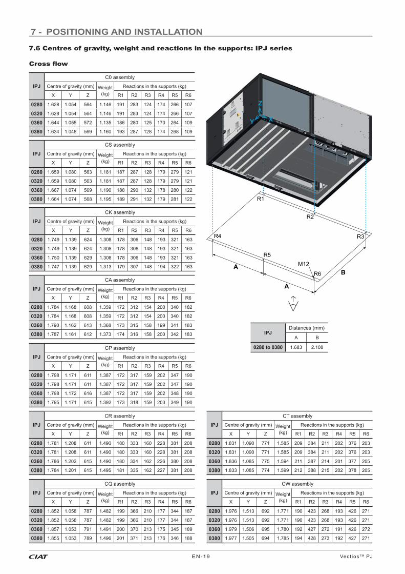
7 - POSITIONING AND INSTALLATION
7.6 Centres of gravity, weight and reactions in the supports: IPJ series
Cross fl ow
R1
R3
R2
A
A
B
R4
R6
R5
Z
XY
M12
IPJ
C0 assembly
Centre of gravity (mm) Weight(kg)
Reactions in the supports (kg)
X Y Z R1 R2 R3 R4 R5 R6
0280 1.628 1.054 564 1.146 191 283 124 174 266 107
0320 1.628 1.054 564 1.146 191 283 124 174 266 107
0360 1.644 1.055 572 1.135 186 280 125 170 264 109
0380 1.634 1.048 569 1.160 193 287 128 174 268 109
IPJ
CS assembly
Centre of gravity (mm) Weight(kg)
Reactions in the supports (kg)
X Y Z R1 R2 R3 R4 R5 R6
0280 1.659 1.080 563 1.181 187 287 128 179 279 121
0320 1.659 1.080 563 1.181 187 287 128 179 279 121
0360 1.667 1.074 569 1.190 188 290 132 178 280 122
0380 1.664 1.074 568 1.195 189 291 132 179 281 122
IPJ
CK assembly
Centre of gravity (mm) Weight(kg)
Reactions in the supports (kg)
X Y Z R1 R2 R3 R4 R5 R6
0280 1.749 1.139 624 1.308 178 306 148 193 321 163
0320 1.749 1.139 624 1.308 178 306 148 193 321 163
0360 1.750 1.139 629 1.308 178 306 148 193 321 163
0380 1.747 1.139 629 1.313 179 307 148 194 322 163
IPJ
CA assembly
Centre of gravity (mm) Weight(kg)
Reactions in the supports (kg)
X Y Z R1 R2 R3 R4 R5 R6
0280 1.784 1.168 608 1.359 172 312 154 200 340 182
0320 1.784 1.168 608 1.359 172 312 154 200 340 182
0360 1.790 1.162 613 1.368 173 315 158 199 341 183
0380 1.787 1.161 612 1.373 174 316 158 200 342 183
IPJ
CP assembly
Centre of gravity (mm) Weight(kg)
Reactions in the supports (kg)
X Y Z R1 R2 R3 R4 R5 R6
0280 1.798 1.171 611 1.387 172 317 159 202 347 190
0320 1.798 1.171 611 1.387 172 317 159 202 347 190
0360 1.798 1.172 616 1.387 172 317 159 202 348 190
0380 1.795 1.171 615 1.392 173 318 159 203 349 190
IPJ
CT assembly
Centre of gravity (mm) Weight(kg)
Reactions in the supports (kg)
X Y Z R1 R2 R3 R4 R5 R6
0280 1.831 1.090 771 1.585 209 384 211 202 376 203
0320 1.831 1.090 771 1.585 209 384 211 202 376 203
0360 1.836 1.085 775 1.594 211 387 214 201 377 205
0380 1.833 1.085 774 1.599 212 388 215 202 378 205
IPJ
CW assembly
Centre of gravity (mm) Weight(kg)
Reactions in the supports (kg)
X Y Z R1 R2 R3 R4 R5 R6
0280 1.976 1.513 692 1.771 190 423 268 193 426 271
0320 1.976 1.513 692 1.771 190 423 268 193 426 271
0360 1.979 1.506 695 1.780 192 427 272 191 426 272
0380 1.977 1.505 694 1.785 194 428 273 192 427 271
IPJDistances (mm)
A B
0280 to 0380 1.683 2.108
IPJ
CR assembly
Centre of gravity (mm) Weight(kg)
Reactions in the supports (kg)
X Y Z R1 R2 R3 R4 R5 R6
0280 1.781 1.208 611 1.490 180 333 160 228 381 208
0320 1.781 1.208 611 1.490 180 333 160 228 381 208
0360 1.786 1.202 615 1.490 180 334 162 226 380 208
0380 1.784 1.201 615 1.495 181 335 162 227 381 208
IPJ
CQ assembly
Centre of gravity (mm) Weight(kg)
Reactions in the supports (kg)
X Y Z R1 R2 R3 R4 R5 R6
0280 1.852 1.058 787 1.482 199 366 210 177 344 187
0320 1.852 1.058 787 1.482 199 366 210 177 344 187
0360 1.857 1.053 791 1.491 200 370 213 175 345 189
0380 1.855 1.053 789 1.496 201 371 213 176 346 188

Vect ios TM PJ EN-20
7 - POSITIONING AND INSTALLATION
7.6 Centres of gravity, weight and reactions in the supports: IPJ series
Tunnel fl ow
R1
R3
R2
A
A
B
R4
R6
R5
Z
XY
M12
R7R8
R9 D
C
R10
Z
Y X
M12
IPJDistances (mm)
A B C D
0200 to 0240 1.356 2.108 766 1.916
0280 to 0380 1.683 2.108 -- --
IPJT0 assembly
Centre of gravity (mm) Weight(kg)
Reactions in the supports (kg)
X Y Z R1 R2 R3 R4 R5 R6
0200 1.402 1.104 569 1.044 154 249 116 156 251 118
0220 1.399 1.107 568 1.050 155 250 116 158 253 118
0240 1.393 1.103 568 1.062 159 254 117 160 255 118
0280 1.607 1.106 571 1.179 191 282 114 193 284 116
0320 1.607 1.106 571 1.179 191 282 114 193 284 116
0360 1.608 1.106 578 1.189 192 284 115 194 286 118
0380 1.606 1.106 577 1.193 193 285 115 195 287 118
IPJTS assembly
Centre of gravity (mm) Weight(kg)
Reactions in the supports (kg)
X Y Z R1 R2 R3 R4 R5 R6
0200 1.461 1.103 570 1.082 148 259 133 149 260 134
0220 1.458 1.106 569 1.088 149 260 132 151 262 134
0240 1.452 1.102 569 1.101 153 263 133 153 264 134
0280 1.658 1.104 571 1.216 188 291 127 189 292 129
0320 1.658 1.104 571 1.216 188 291 127 189 292 129
0360 1.659 1.105 577 1.225 189 293 128 191 295 130
0380 1.657 1.105 576 1.230 190 294 129 192 296 130
IPJTP assembly
Centre of gravity (mm) Weight(kg)
Reactions in the supports (kg)
X Y Z R1 R2 R3 R4 R5 R6
0200 1.732 1.103 535 1.252 209 299 116 210 300 117
0220 1.728 1.105 534 1.258 210 300 115 212 302 117
0240 1.720 1.101 535 1.270 215 304 115 215 305 116
0280 1.866 1.103 615 1.405 175 337 191 175 336 191
0320 1.866 1.103 615 1.405 175 337 191 175 336 191
0360 1.866 1.104 620 1.414 176 339 192 176 339 192
0380 1.863 1.103 619 1.419 178 340 193 177 340 192
IPJ
TW assembly (machine + recovery module)Centre of gravity:
Machine (mm)Centre of gravity:
Module (mm)Weight:Machine
(kg)
Weight Module:
(kg)X Y Z X Y Z
0200 1.345 1.105 568 905 1.093 864 1.029 719
0220 1.342 1.108 567 905 1.093 864 1.035 719
0240 1.337 1.103 567 905 1.093 864 1.048 719
0280 2.364 1.102 693 -- -- -- 1.358 454
0320 2.364 1.102 693 -- -- -- 1.358 454
0360 2.362 1.103 697 -- -- -- 1.367 454
0380 2.358 1.102 696 -- -- -- 1.372 454
IPJ
TW assembly (machine + recovery module)Overall weight
(kg)
Reactions in the supports (kg)
R1 R2 R3 R4 R5 R6 R7 R8 R9 R10
0200 1.749 142 247 127 141 246 126 150 214 209 146
0220 1.755 143 248 127 143 248 127 150 214 209 146
0240 1.767 146 252 128 145 250 127 150 214 209 146
0280 1.812 201 435 272 200 433 271 -- -- -- --
0320 1.812 201 435 272 200 433 271 -- -- -- --
0360 1.822 203 437 273 202 436 271 -- -- -- --
0380 1.826 204 438 273 203 437 271 -- -- -- --
IPJ - 0200 to 0240: TW assemblyRecovery module connected to the machine

Vect ios TM PJEN-21
7 - POSITIONING AND INSTALLATION
7.7 Recommended service clearance
A B
CD
A B
CD
A
B
CD
A
B
CD
VectiosTM PJ - 0090 to 0190: CW assembly
VectiosTM PJ - 0200 to 0380: C0, CS, CK, CA, CP, CR, CQ and CT assemblies
VectiosTM PJ - 0200 to 0380: CW assembly
VectiosTM PJService clearance (mm)
A B C D
0090 to 0190 1.200 1.000 1.000 1.600
Unit not designed to have overhead obstruction.
VectiosTM PJ AssembliesOverall dimensions (mm)
Length Width Height
0090 to 0190
C0, CS 2.225 1.750 1.230
CK, CA, CP, CR 2.230 1.755 1.905
CQ, CT 2.230 1.760 1.975
VectiosTM PJService clearance (mm)
A B C D
0090 to 0190 1.200 1.000 1.000 1.600
VectiosTM PJ AssembliesOverall dimensions (mm)
Length Width Height
0090 to 0190 CW 2.230 2.575 1.905
VectiosTM PJService clearance (mm)
A B C D
0200 to 0240 1.600 1.000 1.000 1.000
0280 to 0380 2.000 1.000 1.000 1.000
VectiosTM PJ AssembliesOverall dimensions (mm)
Length Width Height
0200 to 0240
C0, CS 3.000 2.200 1.230
CK, CA, CP, CR 3.000 2.205 1.905
CQ, CT 3.000 2.210 1.995
0280 to 0380
C0, CS 3.650 2.200 1.230
CK, CA, CP, CR 3.655 2.205 1.905
CQ, CT 3.655 2.210 1.995
VectiosTM PJService clearance (mm)
A B C D
0200 to 0240 1.600 1.000 1.000 1.000
0280 to 0380 2.000 1.000 1.000 1.000
VectiosTM PJ AssembliesOverall dimensions (mm)
Length Width Height
0200 to 0240 CW 3.000 3.015 1.905
0280 to 0380 CW 3.655 3.015 1.905
VectiosTM PJ - 0090 to 0190: C0, CS, CK, CA, CP, CR, CQ and CT assemblies

Vect ios TM PJ EN-22
7 - POSITIONING AND INSTALLATION
7.7 Recommended service clearance
VectiosTM PJ - 0200 to 0380: T0 and TS assemblies VectiosTM PJ - 0280 to 0380: TP assembly
A B
CD
VectiosTM PJ - 0200 to 0240: TP assembly
VectiosTM PJ - 0200 to 0380: TW assembly
A B
C
D
A B
C
D
Unit not designed to have overhead obstruction.
VectiosTM PJService clearance (mm)
A B C D
0200 to 0240 1.000 1.000 1.300 2.200
0280 to 0380 1.000 1.000 1.600 2.200
VectiosTM PJService clearance (mm)
A B C D
0200 to 0240 1.000 1.000 1.300 2.200
VectiosTM PJService clearance (mm)
A B C D
0200 to 0240 1.000 1.000 1.300 2.200
0280 to 0380 1.000 1.000 1.600 2.200
VectiosTM PJ AssemblyOverall dimensions (mm)
Length Width Height
0200 to 0240 T0 & TS 3.000 2.200 1.230
0280 to 0380T0 & TS 3.650 2.200 1.230
TP 3.655 2.210 1.905
VectiosTM PJ AssemblyOverall dimensions (mm)
Length Width Height
0200 to 0240 TP 3.865 2.200 1.230
VectiosTM PJ AssemblyOverall dimensions (mm)
Length Width Height
0200 to 0240 TW 4.665 2.210 1.905
0280 to 0380 TW 4.465 2.210 1.905

Vect ios TM PJEN-23
8 - ELECTRICAL CONNECTION
8.1 Installation norms
Important: All connections in the site are the responsibility of the installer. These connections are always made as per the current regulation. Always refer to the wiring diagram provided with the unit.
To prevent electrical shocks, make all electrical connections before energizing the unit. Check that the automatic switch is closed. Omitting this can cause personal damage. Make the ground connection before any other electrical connection.
V-220004
V-220005
The installer must provide electrical circuit protections according to the effective legislation.
Example:On a 400 V - 3 ph - 50 Hz power supply, the individual phase voltages were measured with the following values:
AB = 406 V; BC = 399 V; AC = 394 V
Average voltage = (406+399+394)/3=1199/3 = 399.7 i.e. 400 V
Calculate the maximum deviation from the 400 V average:
(AB) = 406 - 400 = 6 -> % = 100 x 6 / 400=1.5
(BC) = 400 - 399 = 1 -> % = 100 x 1 / 400=0.25
(CA) = 400 - 394 = 6 -> % = 100 x 6 / 400=1.5Moteur Motor
Wiring must be selected based on:
● The maximum power input, taking into account all the options it features (refer to the technical brochure and the name plate).
● The distance between the unit and its power source.
● The protection to be placed at the power source.
● Neutral operating conditions.
● The electrical connections (refer to the wiring diagram provided with the unit).
● The temperature the wiring is exposed to;
● The fi tting method.
After wire sizing has been completed, the installer must verify the appropriate means of connection and defi ne any modifi cations necessary on site.
Important: It is the responsibility of the installer to protect the unit from overvoltage coming from the mains or voltage spikes caused by lightning. Depending on the geographic location and the type of mains network (buried or overhead), a lightning rod needs to be installed. Check the local electrical codes and regulations. Failure to comply with the requirements of standards in force in the country of installation will void the warranty.
Power cable access routing
The power cables can be routed into the electrical box for the units:
● Via the panel located under the electric panel.
● Via the base of the unit
It is important to check that the power cable bend radius is compatible with the connection space available inside the electric panel.
8.4 Electric panel
All units include a fully wired electrical panel, with forced ventilation.
The access door is insulated to prevent condensation. This door has hinges + quarter-turn latches.
These latches of stainless steel have triangular insert 8 mm (supplied wrench). The closing is done by rotating 90º (anti-clockwise): it brings the latch to the locked position.
Wire sizing is the responsibility of the installer to suit the characteristics of the installation site and comply with applicable regulations.
To perform the electric installation of the unit (cable glands, wire sizing and their calculations, protections, etc.), refer to the information provided in:
● The technical brochure of this series.
● The name plate data.
● The wiring diagram included with the unit.
● Norms in effect that regulate the installation of air conditioning units and electrical receivers in the country of installation.
8.3 Wire sizing
Picture exterior
Dual locks can function as hinges or can be used to remove the door.
Note: Check that the locks are not blocked. Open them with a 4 mm Allen wrench (in an anti-clockwise direction).
8.2 Power supply
Verify that power supply agrees with the unit name plate and that the voltage remains constant.
Warning: Operation of the unit with an incorrect supply voltage or excessive phase imbalance constitutes misuse which will invalidate the manufacturer’s warranty. If the phase imbalance exceeds 2% for voltage, or 10% for current, contact your local electricity supplier at once and ensure that the unit is not switched on until corrective measures have been taken.
Voltage phase imbalance (%)
% imbalance =100 x max. deviation from average voltage
average voltage

Vect ios TM PJ EN-24
The grounding lug (PE), located on the panel plate, is used to earth the frame of the unit.
V-220004
Customer connection
8.5 Vectic electronic control
Vectic electronic control is basically comprised of a control board, sensors, a VecticGD graphic terminal, a TCO user terminal (optional) and a BMS card (optional).
Note: Refer to the Vectic control brochure to obtain more detailed information on its operation.
By default, this control is supplied with a VecticGD graphic terminal, installed on the unit’s electric panel, but it can also be remotely connected:
● Up to 50 metres, it can be connected directly with telephone wire.
● From 50 to 200 metres, it is necessary to use the TCONN bypass cards and AWG 20/22 shielded cable with 2 twisted pairs.
Vectic graphic terminal TCO user terminal
1
2
3
4
5
7
8
6
The TCO user terminal (optional) can be installed in the electrical panel when the graphic terminal is remotely connected.
The fan for cooling the electric panel, the VecticGD terminal and the ground connector, all located on the door, must be disconnected before removing the door.
Electrical components are identifi ed and all wires are numbered. It permits easy tracing and diagnostics.
Power cables are identifi ed with the colors: black (L1) - Brown (L2) - grey (L3) - yellow/green (Ground).
8 - ELECTRICAL CONNECTION
PE
The main components of the unit are connected in intermediate boxes located next to these components.
● BOX1: Motor-compressor circuit 1
● BOX2: Motor-compressor circuit 2 (models 0200 to 0380)
● BOX3: Mixing box
● BOX4: Indoor unit
● BOX6: Return box (optional)
The following image shows the location of boxes in a two-circuit unit with “Cross fl ow” assembly:
No. VectiosTM PJ 0090 to 0380
1 Main power supply 400 III (±10%) 3 Wires + Ground + Neutral
2Remote connection of VecticGD graphic terminal (by default it’s installed on the electric panel)
telephone cable 6 wires standard (RJ12 connector)
4 Remote off/on (optional) 2 wires
5 Main failure signal (optional) 2 wires
6 Circulation pump signal for HWC (antifreeze sec.) (opt.) 1 wire
7Ambient probe
NTC 2 wires
8 RS485 5 wires
9 Air quality probe (optional) 3 wires
In this case, it´s posible to install the TCO user terminal on the electric panel.
Up to four RS485 ambient probes can be connected in series on the fi eld-bus of the control board.
BOX1
BOX2
C1
C2
C3
C4
BOX3
BOX6
BOX4
CE
Vext1
Vext2
Vint1 Vint2

Vect ios TM PJEN-25
The client must connect on-site the following probes:
● Ambient NTC (standard) or RS485 (optional).
● Air quality (optional).
● Outdoor humidity (optional).
These probes are supplied inside the electric panel.
Please refer to the wiring diagram and the Vectic control brochure, both provided with the unit.
8.7 Sensors connection by the costumer
Connection of the ambient probe
● Open the case using a fl athead screwdriver in the slot, paying extra care not to damage the electronic parts.
● Fasten the rear of the sensor case to the panel or the wall (for fastening the case, use the screws supplied with the fastening kit, paying attention to use the proper spacers, to not damage the sensor’s electronics).
Note: If the unit needs the outdoor humidity probe, used with enthalpic or thermoenthalpic free-cooling, this one (S5h) will be connected in the place of the ambient probe (S5a). In this case it is necessary to use a RS485 ambient temperature probe connected on the Field-bus.
Connection of the outdoor humidity probe (optional)
The outdoor humidity probe (optional), necessary for the enthalpic and thermo-enthalpic free-cooling, must be installed on-site, on the hood of the fresh air intake.
● Open the case by turning the top cover anticlockwise (fi g1).
● Fasten the rear of the sensor case to the side panel of the hood (use the screws supplied together with the probe) placing the screws in the holes provided (fi g.2).
● Make sure that the screws that hold the board protective cover are fastened tightly (fi g.3).
● Close the sensor by turning the cover clockwise (fi g.4).
8.6 Location of sensors on the machine
4-way valve(heat pump)
Outdoor fan
Compressor
High press.pressostat
S3Supply air probe
Outdoor temperature probeS2
S7 (*)High pressure transducer S1
Return air probe
S4Mixingprobe
Discharge Tklixon switch
Fresh air
Air extraction
S5aAmbient air probe
S10Air quality probe (opt.)
Outdoor coil
Indoor coil
Indoor fan
Electronicexpansion
valve
S6 (*)Low pressure transducer
S8 (*)Suction temperature probe
8 - ELECTRICAL CONNECTION
(*) In units with 2 circuits:
• Low pressure transducers: S6 (circ.1) and S11 (circ.2)
• High pressure transducers: S7 (circ.1) and S12 (circ.2
• Suction temperature probes: S8 (circ.1) and S9 (circ.2)
Unit 1 circuit
- 1 to 4 RS485 probes (connector J10): with AWG20 section cable, single braided pair preferably shielded with drain wire + Power supply 24 Vac (2 wires).
* Temperature:
S21 to S24.
* Temperature + humidity:
S31 to S34.
Note: in the case of more than one probe, connection of the probes in series, in the RS485 network. Please, refer to the control manual.
S5a
105
B5 (J3)
106 Electricpanel
NTC NTC
S21 (T)S31(T+H)
+(G) (G0) TxRx-
TxRx+ GND
Electricpanel
B10
110
No1
111 112 113 114
24Vac
AWG
20
RS485network
(fi g.1) (fi g.2)
(fi g.3) (fi g.4)
- This probe must be fastened to the panel or the wall of the room to be conditioned, at ca. 1.5 m height.
Electrical connection● Make the electrical connection according to the unit
confi guration:
- NTC Probe S5a: B5 (connector J3): with 2 x 1,5 mm2 section cable, wi th in a maximum distance of 30 meters.

Vect ios TM PJ EN-26
Outdoorhumidity
probe
The installer must feed the W34 cable through the M16 feedthrough to connect it in the BOX3, located inside the unit, behind the side access panel.
Electrical connection
BOX3 (teminals)Black: 35Brown: 31Grey: 36
Probe (teminals)Black: G+Brown: MGrey: H
Connection of the air quality probe
Installation in the environment
● This probe must be fi xed to the interior wall of the room to be conditioned, at ca. 1.5 m height in the room and at least 50 cm from the next wall.
● It should never be mounted:
- On outside walls.
- In niches or behind curtains.
- Above or near heat sources or shelves.
- On walls covering heat sources such as a chimney.
- In the radiation range of heat sources and lighting bodies e.g. spotlights.
- In areas exposed to direct solar radiation.
Duct-mounted
M16x1,5
Ø > 13mmØ > 0.51“
19mm0.75“
90 ±0.3mm3.54 ±0.11“
5mm0.2“
60 ±0.3mm2.36 ±0.11“
Ø > 16mmØ > 0.63“
6mm0.24“
This version can be connected to the air duct in these two ways:
Electrical connection
This probe (S10) is confi gured as analogue output 4…20 mA (0..2000 ppm), in the analogue input B10 of the control board (connector J18).
Recommended cable section : 1,5 mm2.
+V
GND
RH
T
CO2
GND
1
2
3
4
5
6
110
111
109
B10 (J18)
S10
Electricpanel
+V
GND
GND
CO2
NC
Tpassive
Tpassive
1
2
3
4
5
6
7
110
111
109
B10 (J18)
S10
Electricpanel
Environment: Duct-mounted:
8 - ELECTRICAL CONNECTIONHumidity probe position
W34

Vect ios TM PJEN-27
9.1 Checks in the axial fans
● Before commissioning, check the blade rotation direction and that the axis turns without strokes nor vibrations.
● Once running, check the operation conditions: pressures, fl ows and consumptions.
● With electronic fans (standard), check that they adapt their rotational speed based on the condensation or evaporation pressure.
Note: Optionally these units can be supplied with two-speed fans.
9.2 Checks in the EC plug-fans
● Before commissioning, check the blade rotation direction and that the axis turns without strokes nor vibrations.
● Once running, check the operation conditions: pressures, fl ows and consumptions.
● The coupling of characteristic curves of the fan and the room is very important, so that the fl ows and pressures provided to the duct network are as required.
● The variable-speed plug-fans, both supply and return, have a fl ow control pressostat. This pressostat comes from the factory adjusted to the indicated fl ow. However, the fl ow for different conditions can be readjusted on site from the VecticGD graphic terminal (please refer to the Vectic control brochure).
9 - FANS AND AIR DUCTS
Access to the outdoor unit from the fans
For some maintenance tasks, it may be convenient to access the outdoor unit by lifting the cover with the fan(s) (depending on the model).
First, the power supply to the fan must be disconnected.
Each fan features two quick-release connectors (power and control) inside the compressor box.
Then, the cover must be unscrewed.
This is fi xed to the machine using M6 Allen screws.
Ring screws (not supplied with the unit) are to be fi xed to the M10 hex nuts existing on the cover. The lifting slings will be hooked to these ring screws.
● Lid with 1 fan (weight 78 kg): 3 nuts.
● Lid with 2 fans (weight 145 kg): 4 nuts.
Important: These nuts are only intended to lift the cover.
Flow control pressostat
9.3. Checks in the centrifugal fans (optional)
If the unit is equipped with centrifugal return fans (available in CQ and CT assemblies):
● Before commissioning, check the blade rotation direction and that the axis turns without strokes nor vibrations.
● Once running, check the operation conditions: pressures, fl ows and consumptions.
● The overlapping of characteristic curves of the fan and the room is very important, so that the fl ows and pressures provided to the duct network are as required.

Vect ios TM PJ EN-28
The air supply and return ducts must be calculated in accordance with the nominal fl ow and the unit’s available pressure (refer to the technical characteristics table).
The duct calculation and design must be made by qualifi ed technical personnel.
It is advisable to take into consideration the following recommendations:
● Curves in the fan supply outlet(s) must be avoided. It is recommendable to have a straight section of duct measuring approximately 1 metre. If it is not possible, they must be as smooth as possible, using indoor defl ectors when the duct is of large dimensions.
● When making the ducts, direction sharp changes must be avoided since they can generate occasional pressure drops, which affect the available pressure and the fl ow. The location of discharge and aspiration grilles must be studied carefully to avoid the air recirculation and the transmission and generation of noises to the interior.
● Consideration should be given to the need to install fi lters on the return ducts, taking into account any particles in suspension existing which could settle inside the machine (e.g. textile fi bres).
● Flexible connections must be made between the ducts and the unit that avoid the noise and vibration transmission.
● No matter the type of ducts used, they must be isolated and not be composed of materials that propagate fi re nor expel toxic gases in the event of a fi re. The internal surfaces must be smooth and should not pollute the air that circulates within them. In any case, the effective legislation about this issue must be respected.
9.4 Air ducts connections
9 - FANS AND AIR DUCTS
Pulley and belt calibration
Belt tension:
After fi xing the pulleys on the same plane, the belt tension is made by tightening the tensor screw.
Excessive tension on the belt can lead to premature wear on the assembly. Insuffi cient belt tension can cause slippage, overheating and premature wear of the belt.
It is essential to tension the belts using the “Defl ection test” described below:
● The belt tension must be checked and corrected using a suitable measuring instrument (tensiometer or dynamometer).
● “Ea” calculation:
- Ea = (e x E)/100 = deformation in mm for a pulley centre distance of 100 mm
Belt type f(N) d (mm) E (mm)
SPZ 25
56 ≤ 71 2.45
< 71 ≤ 90 2.20
< 90 ≤ 125 2.05
125 1.90
Important: During commissioning, the belt tension must be checked after 48 hours of operation.
The belt tension must be checked in all cases and before system start-up.
Load to be applied per belt f (N)
Small pulley diameter (mm)
Belt deformation for a pulley centre distance of 100 mm - E (mm)
Pulleys must stay on the same plane
Tensorscrew
Pulleyscrews
Taper pin
● At the centre of the centre distance “e”, apply a force “f”, as determined in the table below, to each belt. Set the belt tension to obtain the calculated defl ection “Ea”.
- e = pulley centre distance in mm
- E = see table below for the value
- f = force appliedV-220004
The centrifugal motorfans are coupled through pulleys and belts. In these fans, the following must be taken into consideration:
Pulley alignment:
● The pulleys must be on the same plane, so it is important to check them with the help of a ruler or a laser aligner.
● In case they are not aligned, remove the pulley screws, and after removing the taper pin, the set of pulley and taper can be slided over the axis (this action can be performed both in the motor as well as in the fan).
Attention: Before performing these operations, it is necessary to verify that the unit is disconnected from mains.

Vect ios TM PJEN-29
Check the connection watertightness.
These units are equipped with a condensate drain pan in the indoor circuit, with a 1/2” M gas threaded plastic drain connection.
This drain pan is removable for easy cleaning. It is important to check that the drain is not clogged. The pan is secured to the unit using 4 M6 Allen screws.
Optionally, this pan can be made of stainless steel for corrosion protection.
With outdoor temperatures which are lower than 0ºC the necessary precautions must be taken to prevent the water in the drain ducts from freezing.
Siphon installation norms
Perform the assembly as per the scheme of the attached starting diagram:
● Pan in overpressure: It is installed to avoid the access through the drain piping of bad smells.
● Pan in underpressure: Besides the previous application, water must be sucked from the pan:
- For the correct siphon design, the “A” height must be at least twice that of the underpressure (mm.w.c) where the condensate pan is placed.
- The drain piping must be slightly sloped to ease circulation towards the drain.
- The original diameter of the piping must be respected. No reduction can be made.
CONNECT SIPHONMETTRE SIPHON
PONER SIFONV220014
10 - CONDENSATE DRAIN
Important: the water drain pipe must be provided with a siphon to avoid bad smell and water spills
A
Condensates pan in depression
A
Siphon drain
Slight slope5/1000
To drainage
11 - SAFETY ELEMENTS
High pressure pressostat
Connected to the compressor discharge, it will stop its operation when the pressure at that point reaches the setpoint.
It disconnects at 42 bar and it is automatically reactivated.
Magnetothermic switches for line protection
They are located at the beginning of the power lines for the compressors and motor fan(s) to protect them.
Safety at the compressor
These units have a klixon switch on the compressor discharge which stops the operation of the motor when there is excessive heating.
Main door switch
By using a mechanical device, it impedes access to the electric panel when the unit is with voltage.
Low pressure safety
The low pressure safety is done by the Vectic electronic control via the measure of the low pressure transducer.
Automatic switch in the control circuit
Magnetothermal switch that protects the operation circuit against continuous surges as well as against high currents of short duration (short circuits).
Some options are equipped with a separate drain, 1/2” M gas threaded plastic:
● Cooling recovery circuit (CR and CT assemblies).
● Rotary heat exchanger (CW and TW assemblies).
● Gas burner (roofcurb).
Removable pan

Vect ios TM PJ EN-30
11 - SAFETY ELEMENTS
Condensation and evaporation pressure control
This safety, integrated in the control, enables managing the outdoor fan(s) when the units are working in cooling mode with low outdoor temperatures (condensation control) or in heating mode with high outdoor temperatures (evaporation control). This aids the unit’s operation in all the seasons.
With electronic axial fans, the speed control is proportional, based on the average pressure measured by the pressure transducers.
Smoke detector (optional)
In accordance with standard NF S 61-961, this smoke detection station uses a LED to indicate the installation status, and if the probe detects the presence of smoke in the installation, it stops the operation of the unit.
The station is installed in the factory on a panel next to the electrical panel. To reset the station it is necessary to disassemble the protection box.
The probe is placed on a pillar next to the supply fan.
Defrost control
This safety device is intended to eliminate ice which could accumulate in the outdoor coil when the unit is working in heating mode (heat pump units).
Defrosting is carried out by the control depending on the outdoor temperature and the value measured by the low pressure transducer.
Clogged fi lter detector (optional)
Differential pressostat for detection of the fi lter clogging level. The value for alarm signalling is set in factory, depending on the fi lters selected for the unit.
The electronic control allows the settings selection for the clogged fi lter alarm: only indication (by default) or unit stoppage. Manual reset.
Pressure reading is done thanks to two intakes within the air fl ow before and after the fi lter, such that a comparison is made between the pressure of the inlet air to the fi lter (positive) and the supply air of the same to the other side of the evaporating coil (negative).
This safety device is recommended in particular with gas burner.
This pressostat is installed in the factory:
- in the electric panel, for “Cross fl ow” models.
- on a panel next to the indoor coil, for “Tunnel fl ow” models.
Anti-freeze protection for low outdoor temperatures
(optional)
● Electrical heater for protecting the components of the electric panel. This safety device is mandatory for an outdoor temperature lower than -10°C WB.
A reinforced electrical heater is mandatory for a temperature lower than -14°C WB.
The electrical heater(s) is(are) activated when the thermostat installed inside the electric panel detects that the temperature drops below 5°C.
● Compressor with low-temperature protection using an additional crankcase heater: mandatory for an outdoor temperature lower than -10ºC WB.
Activation temperature: -10ºC WB.
● Electrical heater for antifreeze protection of dampers of the mixing box: mandatory for an outdoor temperature lower than -14ºC WB.
Activation temperature: -14ºC WB.
● Electrical heater for protection of the gas burner housing (optional): mandatory for an outdoor temperature lower than -14ºC WB.
Housing temperature for activation: +1ºC.
● Dampers of the mixing box with springs for automatic closing in the case of a cut in power.
Anti-fi re safety
The electronic control can activate an anti-fi re safety device that detains the unit when the return air surpasses a temperature of 60°C (by default).
It cannot return to operation until the temperature has dropped to below 40ºC.
Note: Vectic electronic control allows to select the functioning logic for the fulfi llment of the ERP French fi re regulations.
Control of air fl ow
The supply plug-fans adapt their speed to the average fl ow measured by the differential pressure sensor and the value set as a setpoint in the electronic control.
Smoke detecting station Smoke detecting probe
Air inlet tube
Remote alarm (optional)
Vectic control allows the management of a relay for remote alarm signalling.

Vect ios TM PJEN-31
12.2 Stop-drop on the fresh air intakeThe stop-drop can be installed on the fresh air intake. It is recommended in cases where a high moisture content in the air is foreseen.
The stop-drop (7) is placed after the hood:
● First, the part (4) is placed inside the hood (1), using 3 of the 4.8 self-tapping hex screws. If the stop-drop has been ordered together with the unit, this part will be installed in the factory.
● Next, the side profi les (5) are fi tted onto the side parts of the hood (2), each with 2 of the 4.8 self-drilling hex screws.
● Finally, the profi le (6) is fi tted onto the panel (3). To do this, unscrew the 3 lower screws on the panel (M6 Allen) and screw them back on, attaching the profi le.
12 - FACTORY OPTIONS AND ACCESSORIES
12.1 Dampers hoodsDepending on the assembly chosen, the fresh air and exhaust air damper hoods are supplied folded down, to be fi tted on site by the installer.
The side parts (2) are supplied screwed to the inside panel (3).
1
3
2
2
Each part (2) will be screwed to the panel (3) using 3 screws and to the hood (1) using another 3 screws. These screws are 4.8 self-tapping hex screws and are supplied with the unit.
1
3
2
24
57
6
5
1
2 2
3
6 screws for each part
1
23
Note: Even though the previous images correspond to a “Cross fl ow” assembly, this procedure is also valid for “Tunnel fl ow” assemblies.

Vect ios TM PJ EN-32
12 - FACTORY OPTIONS AND ACCESSORIES
The following image shows the stop-drop placed:
12.3 Fresh air housing (CK, CA, CP, CR, CW, TP 0280 to 0380, TW assemblies)The fresh air housing is supplied disassembled with the unit, for installation on site.
This housing is composed of the parts that appear in the following image. The number of each part corresponds to the order of assembly.
1
3
2
4
5
6
2
7
7
All the screws required for this assembly are supplied in a bag. These screws are 4.8 self-tapping hex.
Note: if the unit incorporates stop-drop, the assembly process is described in the previous section.
First, parts (1) and (2) must be connected. Then, part (3) is put in place. This structure must be fi tted on top of the unit before continuing with the assembly process.
Then, the screen panel (4) is fi tted to the cover and to the lower tab which incorporates the unit.
Before fi tting the trim (6), the folded down hood (5) must be positioned so as to rest against the lower tab of the trim. Next, the trim is screwed onto the screen panel (4). This ensures that the hood is secure but still able to move.
Finally, the hood (5) is raised and the side parts (7) are secured, by being screwed onto the screen panel (4) and onto the hood.
5
6
4
5
6
7
7
Lower tab
7
All the screws required for this assembly are supplied in a bag.

Vect ios TM PJEN-33
12 - FACTORY OPTIONS AND ACCESSORIES
12.4 Passive recovery (CW and TW assemblies)
Transport and handling
The module with the rotary heat exchanger and its support bed are supplied disassembled with the unit, for installation on site.
● The module can be handled safely by using a forklift truck. The base frame features guide rails to accommodate the forks of the fork-lift truck. These guide rails avoid any slippage.
● For transport and lifting up to the roof using a crane, a rocker arm as well as approved slings must be used. These slings are attached on the grips fi tted to the cover of the module.
Guide rails for forks Lifting grips
● First, the fresh air housing (1) is connected. Follow the steps detailed in paragraph 12.3.
● Next, the front panel (2) is secured using 8x40 hex screws.
● Then, the support bed (3) is fi tted. This is fi xed to the panel using 4.8 self-tapping hex screws on the sides and 8x40 hex screws on the front.
● Next, the recovery module is positioned on the support bed but without efforts on it. Do not remove the fork-lift truck until the module is not secured to the unit.
● The module is secured to the unit using 8x40 hex screws. To do this, the side panels must be removed from the module. The right-hand panel (front view) is secured using M6 Allen screws, while the left-hand panel incorporates dual locks.
Note: Check that the locks are not blocked. Open the locks with a 4 mm Allen key (anticlockwise).
● The module is screwed to rest on the support bed using 8x40 hex screws on both sides.
● Finally, raise the hoods (5) and secure the side parts. Follow the steps detailed in the preceding paragraph.
Note: All the screws required for this assembly are supplied secured on the module and the support bed.
Self-tappinghex screws 8x40 hex screws
8x40 hex screws
8x40 hex
1
2
3
4
5
5
Installation of models TW - 0200 to 0240
In this case, before carrying out the steps outlined above, the return air fans module must be connected to the unit.
● The module can be handled safely by using a forklift truck. The base frame features guide rails to accommodate the forks of the fork-lift truck. These guide rails avoid any slippage.
Installation of models TW - 0280 to 0360 and CW
Electrical connection to be made by the costumer:
Note: see the wiring diagram included with the unit for a more detailed information about the wiring.
The connection is done trought the left-hand panels (front view).
PJ unit Recovery module
2
1
2
1
BOX3 BOX5RT
W59RRT
W59
VRR
BOX6CTW
Initial location of the cables for connection:
Connection to be made by the customer:
W58
PJ unit Recovery module
2
1
2
1
BOX3 BOX5RT
W59RRT
W59
VRR
BOX6CTW
W58
Left-handpanels

Vect ios TM PJ EN-34
● The inside of the heat recovery unit module is accessed via the left-hand panel (front view), for maintenance tasks concerning the fi lters and the condensate pan (1/2” M gas threaded plastic drain connection). This panel features dual locks. Check that the locks are not blocked. Open the locks with a 4 mm Allen key (in an anticlockwise direction).
The access panels to the fi lters (G4 or G4+M6) are secured using M4 Allen screws.
Note: The general procedure for removing and cleaning the fi lters is described in chapter “Maintenance”.
Access to the inside of the recovery module
● The wheel motor can be accessed via the right-hand panel (front view). This panel is secured using M6 Allen screws.
Note: All the screws required for this assembly are supplied secured on the fans module.
● First, the fresh air housing (1) is connected. Follow the steps detailed in paragraph 12.3.
● Next, the front panel (2) is secured using 8x40 hex screws.
● The fan module is secured to the unit using 10x30 hex bolts. To do this, the side panels must be removed from the module. The right-hand panel (front view) is secured using M6 Allen screws, while the left-hand panel incorporates dual locks.
● The cover of the unit and the cover of the module are joined using a seal. This is supplied attached to the cover of the module and must be joined to the cover of the unit using 4.8 self-tapping hex screws.
1
2
10x30 hex screws
Seal
Left-hand panel
12 - FACTORY OPTIONS AND ACCESSORIES
● Then, the recovery module is connected as described above.
Left-hand panel
DrainconnectionG4 fi lters on
the exhaust air outlet
Access panel to fi lters, M4 Allen screws
Wheel
G4 fi lters on the fresh air intake
PJ unit TW 0200 to 0240
Return fansmodule
Recoverymodule
PJ unit TW 0200 to 0240
Return fansmodule
Recoverymodule
Initial location of the cables for connection:
Connection to be made by the customer:
BOX6TW
5
4
3
2
1
5
4
3
2
1
W30
W60
W68TW
W67TW
W59RRT
6
1
6
1
BOX6 BOX3
MM
BOX5RT
MW59RRT
W58
BOX6TW
5
4
3
2
1
5
4
3
2
1
W30
W60
W68TW
W67TW
W59RRT
6
1
6
1
BOX6 BOX3
MM
BOX5RT
MW59RRT
W58
Electrical connection to be made by the costumer:
Note: see the wiring diagram included with the unit for a more detailed information about the wiring.
The connection is done trought the left-hand panels (front view).
● For transport and lifting up to the roof using a crane, a rocker arm as well as approved slings must be used. These slings will be hooked on the anchorage points intended for this purpose in its base frame.
Fans module
Recovery module
“Tunnel Flow” unit

Vect ios TM PJEN-35
12.6 Return fans module (models 0200 to 0240 with TP assembly)
Transport and handling
In these models, the module with the return fans is supplied disassembled with the unit, for installation on site.
For transport and lifting up to the roof using a crane, a rocker arm as well as approved slings must be used. These slings are attached on the grips fi tted to the cover of the module.
Installation
First, the three reinforcement parts (1) are fi tted to the base frame of the unit, using the 8x30 hex screws (supplied in a bag).
Liftinggrips
Reinforcement parts
12.5 Enclosure for lower return (models 0200 to 0240 with TS assembly)
Models 0200 to 0240 with TS assembly are supplied factory-set with a lateral air return.
1
3
2
4
1
An enclosure must be fi tted for the lower return, as shown in the image.
All the parts and screws required for this assembly are supplied with the unit.
Lateral return
Lower return
This enclosure is composed of the parts that appear in the following image. The number of each part corresponds to the order of assembly.
First, side part (1) must be connected. Then, parts (2) and (3) are put in place.
M6 Allen screws
Self-tappinghex screws
12 - FACTORY OPTIONS AND ACCESSORIES
All these parts are fi tted to the unit using 4.8 self-tapping hex screws.
Finally, the trim (4) is fi xed using M6 Allen screws.
Next, the module is secured to the unit using 10x30 hex bolts. To do this, the side panels secured with M6 Allen bolts must be removed from the module.

Vect ios TM PJ EN-36
12.7 Air fi lters
● These units include as standard G4 gravimetric fi lters, which can be replaced by:
- G4 gravimetric fi lters with low pressure drop.
- G4 gravimetric fi lters + M6, F7 or F9 folded opacimetric fi lters.
- G4 gravimetric fi lters with low pressure drop + F7 or F9 folded opacimetric fi lters.
- Double stage of folded opacimetric fi lters (M6+F7, M6+F9, F7+F9 or F9+F9).
Note: the fi lters cleaning procedure is explained in the chapter of “Maintenance”
The access panel to the fi lters incorporates dual locks, they can function as hinges or can be used to remove the panel.
Note: Check that the locks are not blocked. Open them with a 4 mm Allen wrench (in an anti-clockwise direction).
12 - FACTORY OPTIONS AND ACCESSORIES
Finally, raise the hoods and secure the side parts.
Access panel
“Cross fl ow” assemblies
Access panel
“Tunnel fl ow” assemblies
● The structure that support the frames with the fi lters has been designed to feature the various combinations of fi lters. The width of the frame is 24 mm for G4 and 48 mm for the remainder.
When the selected combination of frames has less than 98 mm width, the structure incorporates a tensioner to lock the position of the frames.
To extract the frames it is necessary to loosen the screws securing the tensioner.
Electrical connection to be made by the costumer:
Note: see the wiring diagram included with the unit for a more detailed information about the wiring.
The connection is done trought the left-hand panels (front view).
PJ unit TP 0200 to 0240
Return fansmodule
5
4
3
2
1
Return probe
Damperservo
5
4
3
2
1
BOX6
BOX6TP
Initial location of the cables for connection:
Connection to be made by the customer:
5
4
3
2
1
W60TP
W33TP
W68TP
W67TPVR1
VR2
Return probe
Damperservo
PJ unitTP 0200 to 0240
Return fansmodule
BOX6
BOX6TP
5
4
3
2
1
W60TPW33TP
W68TP
W67TPVR1
VR2
Electricpanel
S1
S1
Electricpanel
10x30 hex screws
Left-hand panels

Vect ios TM PJEN-37
12.8 Heat recovery coil
12 - FACTORY OPTIONS AND ACCESSORIES
This option is compatible with C0, CS, CQ, CT, T0 and TS assemblies.
● The function of the heat recovery coil (HRC) is to pre-heat the air that will pass through the main indoor coil. For this, it uses the temperature of an outdoor water installation. Unit’s control doesn’t manage this function.
Note: a three-way valve is supplied with this coil to assemble out of the unit. This valve is not managed by the control.
● The heat recovery coil is assembled inside the unit. It is placed between the main indoor coil and the air fi lters.
● The inlet/outlet connections of the coil are located on a side pillar of the unit. The position is shown in the following diagrams.
D
AB
C 1
2
D
AB
C1
2
Dimensions (mm) A B C D Ø I/O
Crossfl ow
0090 to 0190 899 872 721 443 1/2”
0200 to 0240 1127 1099 721 443 1/2”
0280 to 0380 1127 1099 721 443 1/2”
Tunnelfl ow
0200 to 0240 636 609 968 691 1/2”
0280 to 0380 928 903 884 631 1/2”
“Cross fl ow” assemblies
“Tunnel fl ow” assemblies
1 Outlet 2 Inlet
1 Outlet 2 Inlet
● Coil fi lling:
- It’s mandatory to fi ll the coil with glycol water to prevent the water from freezing.
- Cut off the water supply and let the bubbles generated go up to the highest coil point and eliminate by opening the purger.
- Pour more water into the circuit and repeat the previous steps.
- Activate the water pump (to be foreseen by the installer) and repeat the previous steps until no air noises are heard in the piping, which is when the fi lling of the installation will have been fi nished successfully.
● In case of long unit stops, and forcibly if they happen in the winter season, the coil must be emptied.
● The direction of the water fl ow must be correct and so the following indications must be observed:
HEAT RECOVERY COILBATTERIE RÉCUP. CHALEUR
BATERÍA RECUP. CALORV2200010-R
HEAT RECOVERY COILBATTERIE RÉCUP. CHALEUR
BATERÍA RECUP. CALORV2200011-R
Access panel to the HRC
“Cross fl ow” assemblies
Access panel to the HRC
“Tunnel fl ow” assemblies
● Detail of the heat recovery coil (HRC):
Purger
Water inlet
Water outlet
Drainage

Vect ios TM PJ EN-38
12.9 Electrical heaters
● The auxiliary electrical heaters are ready for operation in two power stages. This heaters are managed by the electronic control of the unit that can activate them in the following cases:
- As a backup in HEATING mode, following the input of all the available compressors.
- In HEATING mode, instead of compressors.
- During the defrosting operation if selected as support.
- As a backup in COOLING mode in accordance with the return and supply temperatures.
● Up to 3 values of total power available for each model:
12 - FACTORY OPTIONS AND ACCESSORIES
Manual reset (120ºC)
Automatic reset (65ºC)
● The electrical heaters incorporate safety thermistors for protection of the unit against excess temperature. One of them has automatic reset and tare value at 65ºC, the other one has manual reset and tare value at 120ºC.
● The electrical heaters are assembled and connected inside the unit. They can be accessed by the same panel that the supply fan.
- “Cross fl ow” assemblies: the heaters are accessed by removing the panels (1) and (2), and then the inside panel (3), all of them fi xed with M6 Allen screws.
Frame attachment screw
1
3
2
● To remove the frame with the electrical heaters it is necessary to disconnect the safety thermistors from the connection box and unscrew the frame attachment screw (M4 Allen).
- “Tunnel fl ow” assemblies: the heaters are accessed by removing the panel (4), and then the inside panel (5), both fi xed with M6 Allen screws.
4
5
Note: with hot water coil it is not possible to assemble the stop-drop.
12.10 Stop-drop in the indoor coil
● The stop-drop can be installed in the indoor coil. It’s recommended in cases where a high moisture content in the air is foreseen or when the air fl ow is high.
● The stop-drop is accessed by that same panels of electrical heaters, since it is placed between the indoor coil and the electrical heaters (see previous images).
- “Cross fl ow” assemblies: panels (1), (2) and (3).
- “Tunnel fl ow” assemblies: panels (4) and (5).
● The stop-drop frames are easily removable. They can be moved by rail by lifting the tab.
Tab
VectiosTM PJ E0L (Low) E0N (Nominal) E0H (High)
0090 to 0120 12 kW 18 kW unavailable
0140 to 0190 12 kW 18 kW 27 kW
0200 to 0380 18 kW 27 kW 36 kW

Vect ios TM PJEN-39
12 - FACTORY OPTIONS AND ACCESSORIES
● Coil fi lling:
- The coil fi lling must be made with the bleeder valve open until water runs through it, which is when it is time to close it.
- Cut off the water supply and let the bubbles generated go up to the highest coil point, which is the same as the bleeder valve, and eliminate by opening the purger.
- Pour more water into the circuit and repeat the previous steps.
- Activate the water pump (to be foreseen by the installer, except with the GREAT COLD option) and repeat the previous steps until no air noises are heard in the piping, which is when the fi lling of the installation will have been fi nished successfully.
● In case of long unit stops, and forcibly if they happen in the winter season, the coil must be emptied.
● To prevent the water from freezing, with this option the unit always has an anti-freezing thermostat. Add glycol to the water if necessary. It is necessary to consult for glycol percentages higher than 20%.
● The direction of the water fl ow must be correct and so the following indications must be observed:
HOT WATER COILBATTERIE D’APPOINTBATERÍA DE APOYO
HOT WATER COILBATTERIE D’APPOINTBATERÍA DE APOYO
Note: With stop-drop in the indoor air coil it is not possible to assemble the hot water coil.
● The hot water coil is assembled inside the unit. The inlet/outlet connections of the hot water coil are located inside the unit. The connection can be established via the unit base using fl exible piping or via the side panel.
The position of the sheet metal precuts on the side panel are shown in the following diagrams.
CA B
1 2
“Cross fl ow” assemblies
CAB
1 2
“Tunnel fl ow” assemblies
Dimensions (mm) A B C Ø I/O
Crossfl ow
0090 to 0190 142 160 158 1 ¼”
0200 to 0240 159 245 158 2”
0280 to 0380 159 245 158 2”
Tunnelfl ow
0200 to 0240 934 280 158 2”
0280 to 0380 1314 280 158 2”
● The pump of the water circuit has to be activated whenever the 3-way valve is switched on. It is the installer’s responsibility to connect the pump to the electronic control, except with the factory-installed GREAT COLD option. Please refer to the wiring diagram provided with the unit.
Operation of the pump with the GREAT COLD option:
- Antifreeze protection: if the water temperature in the coil drops below 4ºC, the control activates the pump and the 3-way valve opens to 100%. The pump stops when 7°C are reached.
- Safety of minimum outdoor temperature: if the outdoor temperature drops below 4ºC, the control activates the pump and the 3-way valve opens to maintain, in the water coil,
1 Outlet 2 Inlet
1 Outlet 2 Inlet
12.11 Hot water coil
● Hot water coil with a three-way valve managed by the electronic control of the unit. The water coil could be activated in the following cases:
- As a backup in HEATING mode, following the input of all the available compressors (by default) or as fi rst control stage.
- As a backup in HEATING mode in accordance with the supply temperature.
- During the defrosting operation if selected as backup.
- With the unit running or shut down if an anti-freeze alarm is triggered.
- With the unit stopped when the outdoor temperature drops below 4ºC. In this case the circulation pump of the water circuit is connected.
- As a backup in COOLING mode in accordance with the return and the outlet temperatures.
● This option always incorporates an anti-freeze thermostat as safety system.
There are two confi guration types available:
- Standard (B0S), the only safety system is the anti-freeze thermostat. This thermostat is accessed via the same panel used for the electrical heaters, if necessary to reset the safety. Consult the images on the previous paragraph.
- Great Cold (B0C), with adittional anti-freeze technology based on the water temperature. This protection is made up of a circulation pump as well as two probes inserted in the input and the output of the coil.
Important: this option is mandatory for an outdoor temperature lower than -20ºC WB. Consult for percentages of glycol water above 20%.
Note: on units with the “Great Cold” option, air supply only may be lateral (factory-confi gured).
a water outlet temperature of 10ºC in ON operating mode and 15ºC in OFF operating mode.

Vect ios TM PJ EN-40
12.12 Gas boiler
Natural or propane gas boiler with modulating actuator, in accordance with the Gas Directive 2009/142/EC, connected to one side of the unit.
12 - FACTORY OPTIONS AND ACCESSORIES
VectiosTM PJ G1L (Low) G1N (Nominal) G1H (High)
0090 to 0190 unavailable Condexa PRO 40(coming soon) Condexa PRO 70
0200 to 0380 Condexa PRO 50(coming soon) Condexa PRO 70 Condexa PRO 100
Up to 3 values of total power available for each model:
Important: The staff responsible for the installation, operation and maintenance of this burner must always strictly follow the instructions given in this manual, as well as in the manufacturer’s (RIELLO) installation and maintenance brochure for the boilers in the CONDEXA series, supplied with the unit.
Characteristics of gas boiler
● The key features of the boiler are:
• Burner with premixing and modulation technology that allows outputs close to 109% (Hi performance).
• Heat exchanger made of stainless steel with a low carbon content.
• Proportional air / gas valve. Low NOx emissions (class 5, according to standard EN 297).
• Condensate drain with siphon.
• Forced draught.
• Electronic ignition.
• Safety devices: safety thermostat, low water pressure safety switch, fl owmeter, Delta-T control, smoke temperature sensor.
• NTC sensor for boiler water temperature regulation.
• Working temperature of water from -7ºC to 100ºC. Consult for percentages of glycol water above 20%.
• Electronic controller with microprocessor and Multifunction LCD display for boiler ’s control, configuration and diagnostics. Possibility of ModBus communication.
• The electronic control of the unit will only manage the boiler connection as heating support depending on the ambient conditions.
●The boiler is connected to the hydraulic circuit of the auxiliary hot water coil (consult paragraph 12.10).
This water circuit, installed inside the unit, is composed of:
• Water coil.
• Circulation pump.
• Expansion vessel.
• Gate valves.
• Safety valve with a tare value of 4 bar.
• Automatic air bleeder valve.
Safety instructions
Safety instructions to be followed by the staff responsible for work with this burner are described below.
● General cautions
Check the condition of the equipment upon delivery. Check that the details on the label, the packing and the name plate match the order. If equipment has been damaged, or there is a shortfall in delivery, notify accordingly.
During the installation, operation and maintenance of the boiler described in this manual, the use must always strictly follow the instructions given in all the chapters of this manual, and in the manufacturer manual provided with this unit.
The boiler must be installed in compliance with current regulations, according the manufacturer’s instructions and by qualifi ed staff, technically specialised in the heating fi eld.
This thermal module must be used only for the applications it was designed for. Any other wrong or unreasonable use must be regarded as improper and therefore hazardous.
In the event of a water leak, disconnect the thermal module from the main power supply, shut off the water supply and promptly notify the Technical Assistance Service, or professionally qualifi ed personnel.
Periodically check that operating pressure in the water circuit is over 1 bar but below the maximum limit specifi ed for the boiler. If this is not the case, contact Technical Assistance Service or a professionally qualifi ed heating engineer.
The following operations shall be necessary if the boiler is not used for a long period of time:
- Switch the boiler OFF at the control panel.
- Turn the magnetothermic switch “off”, placed in the electric panel of the PJ unit.
- Close the fuel cock and heating circuit water cock.
- Drain the central heating circuit if there is any risk of freezing.
Maintenance must be performed on the boiler at least once a year.
This manual and the manufacturer’s manual must be kept with care. If it is lost or damaged, please contact the Technical Assistance Service for a new copy.
The thermal module, before being connected to the hydraulic system, the gas network, and the electrical system, may be exposed to temperatures ranging from 4°C to 40°C. After it can activate the Frost Protection function.

Vect ios TM PJEN-41
Country Category Gas Pressure (mbar) Gas Pressure
(mbar)Italy, Ireland,Great Britain,Portugal, Slovenia,Slovakia, Greece
II2H3+ G20 20 G30/G31 28-30/37
Spain II2H3+ G20 18 G30/G31 28-30/37
Romania, Bulgaria,Turkey, Denmark,Estonia, Sweden,Norway, Latvia,Lithuania, Finland,Russia
II2H3B/P G20 20 G30 30
Hungary II2H3B/P G20 25 G30 30
Poland II2H3B/P G20 25 G30 37
Croatia II2H3B/P G20 20 G30/G31 30
Holland II2H3B/P G25 25 G30 30
Czech Republic,Austria, Switzerland
II2H3B/P G20 20 G30 50
LuxembourgII2H3B/P G20 20 G30 50
II2E3P G20 20 G31 37
BelgiumI2E(S) G20/G25 20/25 -- --
I3+ -- -- G30/G31 28-30/37
France II2E+3+, G20/G25 20/25 G30/G31 28-30/37
Malta, Cyprus, Iceland I3B/P -- -- G30 30
Germany II2ELL3B/P G20/G25 25 G30 50
Regularly check that the condensate drain is free from obstruction.
We recommend cleaning inside the exchanger once a year, extracting jet and burner and removing any installation debris by suction. This operation will be done by personnel from the Technical Assistance Service only.
● Basic safety rulesThe operation of any appliance that uses fuel, electrical power and water demands that a number of fundamental safety precautions be respected. It is forbidden:
- To use electrical devices or equipment, such as switches, appliances, etc. if there is a smell of gas or unburnt products. If so:
• Close the fuel shut-off cock.
• Report the fault immediately to the Technical Assistance Service or a professionally qualifi ed heating engineer.
• Any technical or cleaning activity is forbidden before disconnecting the boiler from the main power supply by switching the magnetothermic switch placed in the electric panel of the PJ unit.
- To tamper with or adjust the safety or control devices without prior authorisation and instructions from the manufacturer.
- To pull, disconnect, or twist the electrical cables coming from the boiler even if it is disconnected from the mains electricity supply.
- To plug or block the condensate drain outlet
- To switch off the appliance if the outdoor temperature may drop to below ZERO (frost hazard).
- To activate the thermal module without water.
● Safety devicesThe triggering of safety devices indicates the malfunction of a potentially hazardous thermal module. Therefore, contact Technical Assistance Service immediately. After a brief pause, it is possible to try and restart the appliance.
Safety devices must be replaced by Technical Assistance Service, using only original parts. Refer to the spare parts catalogue supplied with the appliance. After making the repair, check that the appliance is working properly.
The appliance must not be put in service, even temporarily, when tampered safety devices are not in operation or have been tampered with.
Identifi cation of the boiler
The boiler can be identifi ed as follows:
1- Technical data plate: It indicates the technical and performance data.
1
2
B23-B53-B53p (C63, C63X)
European Directive92/42/EEC:
RIELLO S.p.A.Via Ing.Pilade Riello, 7 37046 Legnago (VR) -
Gas type: Category:
IT
CONDEXA PRO 100Caldaia a condensazione - Chaudierè a condensation - Brennwertkessel - Condenserende verwamingsketel
G20 G25
Qn(max)=
Cod. N°
Pn(max)=
Qn(min)=
IT: G20=20 mbar G30=28-30 mbar G31=37 mbar
Pn(min)=
20115226
19,4 -
6
P.min.G20= 20 mbarIP
G2
0 - 2
0 m
ba
r
230V ~ 50Hz 150 W
FC145000263
0085 /
0085CP0214
NOx:
bar T=90°C
5
X0D
kW
95,16
19,0
97kW
kW
kW
kW
kW
kW
kW
T067692GE
-
-
-
II2H3+
17
CALDAIA REGO
LATA PER:
CHAUDIERE REGLEE PO
UR:
KESSEL GEREG
ELT FUR:
VERWARM
INGSKETEL ING
ESTELD OP:
KEDEL REGULERET TIL:
CENTRALA REGLATA PENTRU:
A KAZAN AZ ALABBI AD
AKTOR
A LETT BEALLITVA:
PAESE DI DESTINAZIONE:
PAYS DE DESTINATION:
LAND
VON
BESTEMM
ING
:
BE
STIM
MU
NG
SLA
ND
:
LAND,HVOR KEDLEN SKAN INSTALLERES:
TARA DE DESTINATIE:
RENDELTETESI ORSZAG
:
PMS=
FIFIFIG2
Key:
Central heating sectionQn Rated heat inputPn Rated useful heat outputIP Electric degree of protectionPmw Maximum operating pressure, DHW circuitPms Maximum operating pressure, CH circuitT Temperatureɳ Effi ciencyD Specifi c fl ow rateNOx NOx class
2- Gas label:Is located on the appliance’s side and states the type of fuel used and the country of destination:
12 - FACTORY OPTIONS AND ACCESSORIES

Vect ios TM PJ EN-42
12 - FACTORY OPTIONS AND ACCESSORIES
Boiler layout
123
4
5
6
7 8
9
21
19
20
22
23
15
14
1110 12 13
16
18
17
ONONONCOCOCCOOONON
IIIIFIDFIDFFFIDFIDFIDFIDFIDFIDFIDDD
CCNN
77
1 Flue gas analysis outlet2 Flue gas exhaust connection3 Gas valve4 Fan5 Combustion chamber6 Electrical panel7 Flue non-return valve8 Drain cock9 Minimum pressure switch10 Main switch11 Return from the hydraulic circuit
of the hot water coil
12 Gas supply13 Discharge to the hydraulic circuit14 Condensate drain connection15 Flow-meter16 Exhaust fl ue probe17 Return probe18 Control panel19 Ignition/detection electrode20 Safety thermostat21 Flow probe22 Automatic bleed valve23 Casing
Installation of the boiler
The boiler is supplied disassembled with the PJ unit, for installation on site.
The hydraulic circuit is assembled inside the PJ unit. This circuit is fi lled with a preload of water mixed with glycol at 20%.
The installer must connect the connecting piping with the boiler.
Note: all this piping system is sent packed together with the boiler.
1
2
3
45
Pump
Expansion vessel
Safety valve
Automaticbleeder valve
Step 1: Remove the panel (1) secured using M6 Allen screws to facilitate the work. Next, connect the piping:
(2) Discharge to the hydraulic circuit of the hot water coil
(3) drain connection of the safety valve
(4) Filling line
(5) Return from the hydraulic circuit of the hot water coil

Vect ios TM PJEN-43
12 - FACTORY OPTIONS AND ACCESSORIES
A
A
ALAALAA
Step 2: Replace the panel (1). The following image shows the panel by the outer side of the PJ unit. Then fi x the clamps supplied to secure the pipes (3) and (4) (M6 Allen screws).
Clamps
M4 Allen fi xing screws for the boiler
Boiler bracket
1
Step 3: Remove the casing of the boiler to screw it to the panel (1). To do this it is necessary to remove the locking screw, and then, pull the front panel outwards and later to the top to decouple it from points A.
Step 4: Drop the boiler on the bracket (6) and screw on the four fi xings of this panel to secure (M4 Allen screws). Then reassemble the casing.
6
Step 5: Finally join the boiler with the piping using elbows and accessories factory-supplied.
Return fromhydraulic circ.
Discharge to hydraulic circ.
Fillingvalve 1/2”
Pressuregauge
Lockingscrew

Vect ios TM PJ EN-44
12 - FACTORY OPTIONS AND ACCESSORIES
Gas connections
The gas connection must be made respecting the installation regulations in force, and sized to ensure the correct gas delivery to the burner.
Before making the connection, check that:
● The gas type is suitable for the boiler. Do not use any fuels other than those provided under any circumstances.
● If the boiler needs to be adapted for use with another gas fuel, contact the Technical Assistance Service to have the necessary modifi cations made. These operations may not be performed by the installer under any circumstances.
● The piping is thoroughly clean.
● The gas meter’s flow rate is capable of ensuring the simultaneous use of all the appliances connected to it. The appliance’s connection to the gas supply line must be carried out in accordance with the current regulations.
● Intake pressure with the appliance in the off position has the following reference values:
- Powered by methane gas: optimal pressure 20 mbar. - Powered by L.P.G.: optimal pressure 35 mbar.● The pressure never falls below 15 mbar.
While it is normal for the intake pressure to decrease while the boiler is in operation, it is advisable to verify that no excessive pressure fl uctuations take place. In order to limit the extent of these types of variations, the diameter of the gas supply line to be used must be assessed based on the length and the pressure drops of the line itself, from the meter to the thermal module.
● If fl uctuations in the gas distribution pressure are encountered, it is recommended to install an appropriate pressure stabiliser upstream of the boiler’s gas intake. For G30 and G31 gas supply, all the necessary precautions must be taken in order to prevent the gas from freezing in the case of extremely low outdoor temperatures.
● If the gas distribution network contains solid particles, install a fi lter on the fuel supply line. When selecting it, consider that pressure drops due to the fi lter should be as low as possible.
● Once the boiler has been installed, check the connections are sealed according to current installation regulations.
Connection at the fl ue
The boiler is supplied as standard in B-type confi guration (B23-B53P-B53P), i.e. pre-fi tted to suction air directly into the installation room and may be converted into a C-type appliance with the use of specifi c accessories.
For fl ue gas extraction and the intake of combustion air, it is essential to use only specifi c pipes for condensing boilers and ensure that they are correctly connected.
Preparation for the condensate drain
GAS 1" M
DN80 DN110794 825
100100
98 98
1217
1199
Diameter of the fl ue gas outlet (fl ue connection):
* Condexa PRO 40 / 50 / 70: DN80
* Condexa PRO 100: DN110
300m
m
Note: dimensions in mm
Optionally, a kit with all the fl ue gas accessories can be supplied:
The condensate produced by the appliance Condexa PRO during normal operation must be extracted using an accessory (siphoned condensate collector).
This accessory must be fi tted below the aforementioned thermal module, in line with the following instructions:
● It is advised to use plastic (PP) piping for building the condensate drainage. Never use copper pipes under any circumstances, as the condensate itself will cause them to rapidly deteriorate.
● The connection pipes used must be as short and as straight as possible. Any curves or sharp bends can lead to hoses becoming clogged and, therefore, can prevent proper condensate discharge.
● Important: The minimum distance between the condensate outlet and the ground must be at least 300 mm to facilitate the proper implementation of the siphon. Therefore, it is essential to provide a roofcurb for installation of the PJ unit on it.
Note: optionally PJ units can be supplied with roofcurb.

Vect ios TM PJEN-45
12 - FACTORY OPTIONS AND ACCESSORIES
Electrical connection
The cables for the electrical connection of the boiler are located on the lower part of the boiler.
The installer must pass these cables through the bottom panel of the PJ unit, and next, route them to the connection box “BOX8-BOI” .
Ø 25mm
● Always maintain a slope angle of over 3° and ensure that the diameter of any condensate drain pipe is greater than that of the connection fi tted at the drain outlet.
● The condensate drain must be connected to the drain and sewage network in such a ways so that the condensate may not freeze under any circumstances.
● Connect the condensate drain hose to a domestic water drain in accordance with national and local legislation and standards.
● Fill the siphon with water before activating on the thermal module in order not to release any combustion products into the environment when the thermal module is fi rst switched on.
● The fi rst section of the condensate drain pipe, which is connected to the condensate outlet from the boiler (Ø 25 mm), must be fl exible pipe to avoid any contact with the discharge pipe.
Boiler control panel
Important: For more information about the electronic control of the boiler refer to the manual of the manufacturer, provided together with the unit.
21 3 4 5 6 7 98ALALI 10
1 255x80 point backlit display (106,4 x 39,0mm)
2 RESET key:
Restores normal operations after a safety shut-down.
3 MENU key:
Switches on the main menu
4 ESC key:
In menu navigation, it enables you to exit a menu item and go back to the previous one.
5 navigation key:
Within a list of parameters if the cursor is located in the right column (values column), move the cursor in the left column (descriptions column).
6 navigation key:
- Within a menu, this allows the navigation down to select different submenus;
- Within a list of parameters, if the cursor is in the right column, it reduces the value of the selected parameter;
- Within a list of parameters, if the cursor is in the left column, it selects the next parameter.
7 navigation key:
- In menu navigation, It allows to enter the selected menu item;
- Within a list of parameters, it allows to confi rm a value or setting.
8 navigation key:
Within a list of parameters if the cursor is located in the left column (descriptions column), move the cursor in the right column (values column).
9 navigation key:
- Within a menu, this allows the navigation up to select different submenus;
- Within a list of parameters, if the cursor is in the right column, it increases the value of the selected parameter;
- Within a list of parameters, if the cursor is in the left column, it selects the previous parameter.
10 Main switch (located on the lower part of the boiler)
W48-BOI W49-BOI
Note: see the wiring diagram included with the unit for a more detailed information about the wiring.

Vect ios TM PJ EN-46
Hydraulic circuit
Circuit fi lling● The charging system is connected to the boiler’s return line.
Automatic fi lling valve 1/2”.
Circuit emptying● In case of long unit stops, and forcibly if they happen in the
winter season, the circuit must be emptied.
● Before emptying the system, switch-off the thermal module’s switch (0) and switch-off the magnetothermic switch placed in the electric panel of the PJ unit.
● Close the water supply shut-off cocks;.
● In order to empty the boiler, fi t a rubber hose (5) (inner diameter int. Ø = 12 mm) to the thermal module’s discharge valve (1).
Filling valve
Pressure gauge
● Before fi lling the system, switch-off the thermal module’s switch (0) and switch-off the magnetothermic switch placed in the electric panel of the PJ unit.
● Make sure that drain cocks (1) are closed before to start the load of the system. Then, the shut-off valves of the hydraulic circuit must be opened.This circuit is fi lled with a preload of water mixed with glycol at 20%.
Immediately repair any leaks or drips that could result in air entering the system.
1
IIIIFIDFIDFFFIDFIDFIDFIDFIDFIDFID● Unscrew the vent valve’s release cap
● Open the shut-off cocks in order to slowly fi ll the system.
● Use the pressure gauge to check that the pressure is rising and the water is exiting through the vent valves.
● Close the shut-off cocks after the pressure reaches 1.5 bar.
● Start-up the circulation pump. This operation can be performed manually from a screen of the Vectic electronic control (on a screen of the “Service menu”, password protected).
● During this stage, check that the air is correctly eliminated.
● Restore the pressure if necessary.
● Stop the pump and start-up again.
● Repeat the last three steps until the pressure is stabilised.
Excessive pressure fl uctuations can cause stress and fatigue to the heat exchanger. Keep the operating pressure constant.
1
IIIIFIDFIDFFFIDFIDFIDFIDFIDFIDFID5N
Parameter Value Unit
General characteristic Colourless, withoutsediment
PH value Min. 6,5 ; Max. 8,0 pH
Dissolved oxygen < 0,05 mg/l
Total iron (Fe) < 0,3 mg/l
Total copper (Cu) < 0,1 mg/l
Na2SO3 < 10 mg/l
N2H4 < 3 mg/l
PO4 < 15 mg/l
CaCO3 Min. 50 ; Max. 150 ppm
Trisodium phosphate None ppm
Chlorine < 100 ppm
Electrical conductivity <200 μSiemens/cm
Pressure Min. 0.6 ; Max. 6 bar
Glycol Max. 20% (only propylene glycol) %
All data in the table refer to water contained in the system after 8 weeks’ operation.
● To prevent the water from freezing, with this option the PJ unit always has an anti-freezing thermostat and water mixed with glycol at 20%. It is necessary to consult for propylene glycol percentages higher than 20%.
Do not use excessively softened water. Excessive water softening (total hardness < 5° f) results in corrosion due to contact with metal elements (pipes or thermal module components).
Water quality requirements
● It is ABSOLUTELY NECESSARY to treat the water system in order for the heat generator to work properly and to guarantee its service life, as well as that of all its components.
The water used for the central heating circuit must conform to the quality parameters given in the following table:
12 - FACTORY OPTIONS AND ACCESSORIES

Vect ios TM PJEN-47
12 - FACTORY OPTIONS AND ACCESSORIES
12.13 Gas burner
Natural or propane gas burner with modulating actuator, in accordance with the Gas Directive 2009/142/EC, installed inside a pre-assembly roofcurb (see EC homologation certifi cate at the end of this manual).
Important: The staff responsible for the installation, operation and maintenance of this burner must always strictly follow the instructions given in this manual, as well as in the manufacturer’s (APENGROUP) installation and maintenance brochure for the burners in the PCH series, supplied with the unit.
Characteristics of the gas burner
● Air is heated by contact with the surfaces of the combustion chamber and the heat exchanger pipes.
- The heat exchanger complies with construction requirements set by EN1196 regulations for equipment where combustion gases produce condensate.
- The combustion chamber is entirely made of stainless steel whilst surfaces of components where condensation occurs (such as pipe bundle and exhaust hood), are made of AISI 441, in order to provide high resistance to condensation.
The following table illustrates the types of stainless steels used:
USA-AIS EN-No COMPOSITION
AISI 430 1.4016 X6 Cr17
AISI 441 1.4509 X2 CrTiNb 18
- The burner is entirely made of stainless steel with special mechanical solutions to ensure optimal reliability and performance levels, as well as high thermal and mechanical resistance.
● The PCH heater is a modulating type; the thermal power output and, therefore, the thermal capacity (fuel consumption) vary according to the demand for heat. When the demand for heat from the environment drops, the heater uses less gas, increasing its performance up to 109% (performance on Hi).
● Inherent safety:
- The performance increase at minimum power is achieved by using a sophisticated air/gas mixing technique and by adjusting at the same time the combustion air and the fuel gas.
- This technology increase the heater safety as the gas valve supplies the fuel according to the air fl ow. The CO2 content, unlike atmospheric burners, remains the same throughout the heater operating range, allowing it to increase its performance when the thermal power drops.
- If there is no combustion air, the valve will not supply gas; if the combustion air fl ow drops, the valve will automatically reduce the gas fl ow yet will keep its combustion parameters at optimal levels.
● Lowest polluting emissions. The premixed burner, in combination with the air/gas valve, ensures a “clean” combustion by emitting a very low level of pollutants.
● The control located inside the burner housing allows the service centre to check and view the working phases and identify any faults that may have occurred.
● The electronic control of the unit will only manage the burner connection as heating support depending on the ambient conditions.
Note: the main technical characteristics of the burner can be found in the technical brochure.
Safety instructions
Safety instructions to be followed by the staff responsible for work with this burner are described below.
● General cautions
This burner module must be used only for the applications it was designed for. Any other wrong or unreasonable use must be regarded as improper and therefore hazardous.
During the installation, operation and maintenance of the burner described in this manual, the use must always strictly follow the instructions given in all the chapters of this operating and maintenance manual.
The condensing warm air heater must be installed in compliance with current regulations, according the manufacturer’s instructions and by qualifi ed staff, technically specialised in the heating fi eld.
When fi rst switched on, conversion between different types of gas and maintenance operations must be carried out only by staff provided by Service Centres authorised by current and older regulations. For more information, please contact us.
The warranty conditions are specified on the warranty certifi cate supplied with this burner module.
The manufacturer declares that the unit has been manufactured in compliance with UNI, UNI-CIG, CEI technical standards and with all relevant legislation, as well as with the 90/396/EEC gas directive and the later 2009/142/EC Directive.
●Up to 3 values of total power available for each model:
VectiosTM PJ G0L (Low) G0N (Nominal) G0H (High)
0090 to 0190 PCH020 PCH034 PCH045
0200 to 0240 unavailable PCH065 PCH080
0280 to 0380 unavailable PCH080 PCH105

Vect ios TM PJ EN-48
● Fuel
Before starting up the heater, make sure that:
- the gas mains supply data is compatible with the data stated on the nameplate;
- the combustion air intake ducts (when fi tted) and the fume exhaust pipes are those specifi ed by the manufacturer;
- the combustion air is supplied in such a way as to avoid even partial obstructions of the intake grille (caused by leaves etc.);
- the fuel intake internal and external seal is checked during the testing stage, as required by applicable standards;
- the burner is supplied with the same type of fuel it has been designed for;
- the system is correctly sized for such fl ow rate and is fi tted with all safety and monitoring devices required by applicable standards;
- the inside of the gas pipes and air distribution ducts for ducted heaters has been thoroughly cleaned;
- the fuel fl ow rate is suitable for suitable for the power required by the burner;
- the fuel supply pressure is between the range specifi ed on the nameplate.
If the burner is not going to be used over a prolonged period the gas supply valve must be closed.
12 - FACTORY OPTIONS AND ACCESSORIES
● Gas leaks
If there is gas smell:
- do not operate electrical switches, telephones or any other object or device that could produce sparks;
- immediately open doors and windows to create an air fl ow to vent the gas out of the room;
- close the gas valves;
- call for qualifi ed staff.
Supplying the gas circuit with pressure higher than 60 mbar is strictly prohibited. Such pressures could cause the valve to break.
● Operation
Do not allow children or inexperienced people to use any electrically powered equipment.
The following instructions must be followed:
- do not touch the equipment with wet or damp parts of your body and/or with bare feet;
- do not leave the equipment exposed to the elements (rain, sun etc....) unless it is adequately protected;
- do not use the gas pipes to earth electrical equipment;
- do not touch the hot parts of the heater, such as the fume exhaust duct;
- do not wet the heater with water or other fl uids;
- do not place any object over the burner;
- do not touch the moving parts of the burner.
General recommendations
● Delivery of the roofcurb with gas burner
Check the condition of the equipment upon delivery. Check that the details on the label, the packing and the name plate match the order. If equipment has been damaged, or there is a shortfall in delivery, notify accordingly.
● Location
These roofcurb with integrated burner are designed to be coupled with an PJ unit (roof-top installation). Make sure they are not fi tted near areas where there is a risk of fi re (fl ammable dust) or explosion, or in areas where aggressive products are kept, e.g. trichloroethylene, perchloric acid, etc.
● Burner identifi cation
The roofcurb with the burner includes a name plate featuring the main gas characteristics as well as the roofcurb serial number.
Roofcurbserial No.
Roofcurb with burner CE certifi cate No.
Burnermodel
Important: The serial number must be used in all communication regarding the unit.
m3/h
mbar
GAS INFORMATION
COUNTRY
GAS
CATEGORY
PIN
CONSUMPT.
PRESSURE
TYPE
WO
Attention: In compliance with the requirements of the Gas Directive 90/396 EEC it is strictly prohibited to alter the burner or the electronic control unit.
● Maintenance
Maintenance operations and combustion inspections must be carried out in compliance with current standards.
Before carrying out any cleaning and maintenance operations, isolate the heater from the mains power supply from the switch located on the electrical system and/or on the shut-out devices.
If the heater is faulty and/or incorrectly operating, switch it off and do not attempt to repair it yourself, but contact our local Technical Service.
All repairs must be carried out by using genuine spare parts.
Failure to comply with the above instructions could compromise the safety of the equipment and invalidate the warranty.
If the equipment is not used for long periods, shut the gas upply off through the gas stopcock and disconnect it from the power supply.
If the heater is to be put out of service, in addition to the above operations, potential sources of hazard on the unit must be removed.
It is strictly forbidden to obstruct the Venturi pipe inlet, located on the burner-fan unit, with your hands or with any other objects.
Any obstruction could cause a backfi re from the premixed burner.

Vect ios TM PJEN-49
12 - FACTORY OPTIONS AND ACCESSORIES
Country Category Gas Pressure (mbar)
Gas Pressure (mbar)
Austria, Switzerland II2H3B/P G20 20 G30/G31 50
Belgium<70kW I2E(S)B,I3P G20/G25 20/25 G31 37
Belgium>70kW I2E(R)B,I3P G20/G25 20/25 G31 37
Germany II2ELL3B/P G20 20 G30/G31 50
Denmark, Finland, Greece, Sweden, Norway, Italy, Czech Republic, Estonia, Lithuania, Slovenia, Albania, Macedonia, Bulgaria, Romania, Croatia, Turkey
II2H3B/P G20 20 G30/G31 30
Spain, United Kingdom, Ireland, Portugal, Slovakia
II2H3P G20 20 G31 37
France II2Esi3P G20/G25 20/25 G31 37
Luxembourg II2E3P G20/G25 20 G31 37/50
Netherlands II2L3B/P G25 25 G30/G31 50
Hungary II2HS3B/P G20/G25.1 25 G30/G31 30
Cyprus, Malta I3B/P -- -- G30/G31 30
Latvia I2H G20 20
Iceland I3P -- -- G31 37
Poland II2E3B/P G20/G2.350 20/13 G30/G31 37
Russia II2H3B/P G20 20 G30/G31 30
Country table - gas category:
Transport and installation
Follow the recommendations given in section 7.4 which details how to handle and fi t the adjustable roffcurb, and how to fi t the PJ unit onto this roffcurb.
Electrical connection of the burner
It is necessary to communicate the burner control with the electric panel of the PJ unit. The costumer must connect the cables coming from the burner to the connection box “BOX6-QUE” that is located inside of the PJ unit. This box is accessed via the same panel that the supply fans.
Connection of the outlet probe
The connection of the outlet temperature probes must be performed on-site. This probe is supplied inside the electric panel of the PJ unit.
Make the electrical connection of the probe (S3) to the connection box “BOX6-QUE” that is located inside of the PJ unit, using 2 x 1mm2 section cable.
Note: this cable is not supplied with the probe.
Please refer to the wiring diagram and the Vectic electronic control brochure, included with the unit.
For the electrical connections, remove the top cover of the sensor. Remove the cover by rotating it anticlockwise.
In order to guarantee the correct measurement of the outlet air temperature this probe will be positioned at 1.5 metres as a minimum from the outlet mouth at the bottom of the duct and as near to the middle as possible inside this duct. The probe is connected to the air duct using the special fastening bracket.
● Fasten the bracket to the air duct;
● Insert the rod on the bracket to the required depth;
● Tighten the screw on the bracket to fasten.
3 x M3x10 self-tapping male
Rotate to open
Rotate to close
Clamp for attaching to the duct
Screw to fix the probe position (PT3.5x12)
61
120°120°
25
42
No. 3 holes Ø 2.75
Ø 17
37,5
43,3= =
Detail of clamp dimensions (mm)
S3
DPDT011000
40 46
GND B3
BOX6-QUE
BOX6-QUE
The following image shows the location of the connection box “BOX6-QUE”.
Note: see the wiring diagram included with the unit for a more detailed information about the wiring.
Initial location of the cables for connection:
Connection to be made by the customer:
PJ unit
Roofcurb with burner
BOX6QUE
2
1
2
1BurnercontrolW49-QUE
W48-QUE
PJ unit
Roofcurb with burner
BOX6QUE
2
1
2
1BurnercontrolW49-QUE
W48-QUE

Vect ios TM PJ EN-50
12 - FACTORY OPTIONS AND ACCESSORIES
Gas connection
Use the gas line connections only with EC certifi ed components.
The PCH module is supplied complete with a dual gas valve, gas stabiliser and fi lter. All components are fi tted inside the burner housing.
To complete the installation, as required by current standards, an anti-vibration joint and a gas valve must be fi tted.
If the burner is not going to be used over a prolonged period the gas supply valve must be closed.
Important: For a correct maintenance, connect the PCH module by means of a seal and swivel gasket. Avoid using threaded connected directly on the gas connection.
During the installation, tighten the external gas supply pipe but without exceeding the tightening torque of 150 Nm.
Note: A EN216 certifi ed gas fi lter with fi ltration level lower or equal to 50 micron must be used, with no pressure stabiliser, a wide range gas fi lter must be used since the fi lter supplied as standard, upstream of the gas valve, has a limited area.
Important: It is strictly prohibited to supply gas to the circuit with pressure higher than 60 mbar. Such pressures could cause the valve to break.
If pressure are higher than 60 mbar, a pressure reducer must be installed at least 10 m away and no pressure stabiliser must be fi tted between the pressure reducer and the heater, but leaving the gas fi lter.
Key:1. Main burner gas solenoid valve2. Pilot burner gas solenoid valve3. Pressure stabiliser:4. Safety gas solenoid valve5. Gas fi lter (small section)6. Anti-vibration joint7. Gas fi lter (large section)8. Gas valve
Gas supply: Ø 3/4’’
Gastype Gas settings
PCH020 PCH034 PCH045 PCH065 PCH080 PCH105min. max. min. max. min. max. min. max. min. max. min. max.
G20
Air supply pressure mbar 20 [min 17-max 25]
Ø pilot nozzle mm 0,7
Gas consumption (15°C-1013mbar) m3/h 0,51 2,01 0,80 3,69 0,90 4,66 1,31 6,88 1,74 8,68 1,90 10,58
Carbon dioxide - CO2 content % 8,8 9,1 8,7 9,1 8,7 9,1 8,7 9,1 8,7 9,1 8,5 9,1
Fumes temperature ºC 39 113 31 94 30 94 31 86 26,5 70 28 80
Fume mass fl ow rate (max.) kg/h 31 57 72 107 135 165
Gas butterfl y valve mm 5,8 7,4 7,5 11,0 12,2 15,8
G25
Air supply pressure mbar 25 [min 17-max 30] (20 for Germany)
Ø pilot nozzle mm 0,7 (0,75 for Germany)
Gas consumption (15°C-1013mbar) m3/h 0,59 2,34 0,93 4,29 1,05 5,41 1,53 8,00 2,02 10,1 2,21 12,30
Carbon dioxide - CO2 content % 8,8 9,0 8,6 9,0 8,8 8,9 8,8 9,2 8,6 8,9 8,8 9,0
Fumes temperature ºC 39 113 31 94 30 94 31 86 26,5 70 28 80
Fume mass fl ow rate (max.) kg/h --
Gas butterfl y valve mm Not necessary
G30
Air supply pressure mbar 30 [min 25-max 35] - 50 [min 42,5-max 57,5]
Ø pilot nozzle mm 0,51
Gas consumption (15°C-1013mbar) m3/h 0,40 1,58 0,63 2,90 0,71 3,65 1,03 5,39 1,36 6,80 1,49 8,30
Carbon dioxide - CO2 content % 10,8 11,4 10,8 11,5 10,8 10,9 10,7 11,3 11,2 11,6 10,9 11,2
Fumes temperature ºC 39 113 31 94 30 94 31 86 26,5 70 28 80
Fume mass fl ow rate (max.) kg/h --
Gas butterfl y valve mm 3,7 5,0 5,2 6,5 7,0 9,3
G31
Air supply pressure mbar 30 [min 25-max 35] - 37 [min 25-max 45] - 50 [min 42,5-max 57,5]
Ø pilot nozzle mm 0,51
Gas consumption (15°C-1013mbar) m3/h 0,39 1,55 0,62 2,85 0,70 3,60 1,01 5,31 1,34 6,70 1,47 8,18
Carbon dioxide - CO2 content % 9,3 9.,8 9,2 9,7 9,3 9,4 9,4 9,6 9,3 9,6 9,1 9,6
Fumes temperature ºC 39 113 31 94 30 94 31 86 26,5 70 28 80
Fume mass fl ow rate (max.) kg/h 24 45 58 84 107 130
Gas butterfl y valve mm 3,7 5,0 5,2 6,5 7,0 9,3
1 2 3 4 5 6 7 8
Included in the burner module To be carried out by the installer

Vect ios TM PJEN-51
12 - FACTORY OPTIONS AND ACCESSORIES
Connections at the fl ue
Terminal confi guration
Type B23POpen combustion circuit: the gases produced by the combustion are discharged outside, on a wall or on the roof, and the combustion air is directly drawn from the site where the equipment is installed.
In this case, the standards UNI-CIG 7129 and UNI-CIG 7131 require the provision of suitable vents on the walls.
Selection Guide
If the terminal is not directly connected to the heater and, therefore, extra routing is required, according to the length of the ducting, the diameter of the selected terminals, extensions and bends must be checked.
After establishing the routing, the pressure drop must be calculated for each component; each component has a different pressure drop value as the glue gases fl ow rate is different.
The pressure drops of each component identifi ed must be added, checking that the result is no higher than the value available for the PCH heater module used; if a combustion air supply pipe is fi tted, the pressure losses must be added to the fume exhaust pressure drop.
If the sum of pressure drops caused by the fi ttings are higher than the pressure available at the exhaust, ducting with higher diameter must be used, rechecking the calculation; a pressure drop higher than the pressure available at the fume exhaust reduces the heater module thermal output.
If the duct routing requires the use of bends, the length required must be subtracted from the available length:
• Ø 80 wide radius bend at 90° EqL = 2.1m
• Ø 80 wide radius bend at 45° EqL = 1.1m
• Ø 100 wide radius bend at 90° EqL = 3.5m
• Ø 100 wide radius bend at 45° EqL = 1.6m
PCH model 020 034 045 065 080 105Pressure avail. at the exhaust (Pa) 80 90 100 120 120 120Component Pressure drop (Pa)Ø 80 pipe (1 metre) 0,4 1,3 2,1 4,6 7,3 11,0Ø 100 pipe (1 metre) 0,1 0,4 0,6 1,3 2,2 3,5Ø 80 wide radius bend at 90° 0,9 2,8 4,4 9,5 15,0 22,2Ø 100 wide radius bend at 90° 0,3 1,4 2,2 5,1 8,2 12,0Ø 80 wide radius bend at 45° 0,5 1,4 2,2 4,6 7,3 11,0Ø 100 wide radius bend at 45° 0,2 0,6 1,0 2,2 3,5 5,5Ø 80 - 100 adaptor 0,2 0,6 1,0 1,2 1,8 2,7Ø 80 hooded terminal 2,0 5,0 10,0 14,0 16,0 20,0Ø 100 hooded terminal 1,5 3,7 7,5 10,5 12,0 15,0
Important: The horizontal sections of fl ue, which make up the fume exhaust, must be installed with a slightly incline (1°- 3°) towards the heater, in order to prevent the build of condensation in the exhaust.
Pressure drop for terminals and exhaust ducting:
Note: It is compulsory to fi t an IP20 safety mesh to prevent solids with a diameter higher than 12mm from entering the combustion air intake; at the same time, the mesh opening must not be lager than 8mm.
Type C13Sealed combustion circuit (type “C”) connected to a horizontal terminal on the wall by means of its own ducting.
Type C33Sealed combustion circuit (type “C”) connected to a vertically installed terminal (on the roof) by means of its own ducting.
Type C53Sealed combustion circuit (type “C”) connected by means of its own ducting split in two terminals which could end up in areas with different pressure (such as a ducting connected to the roof and a second one connected to the wall).
Type C63Sealed combustion circuit (type “C”) connected to an approved and separately sold combustion air supply and combustion products exhaust system.
This PCH burner module is fi tted with a watertight combustion circuit and with the burner fan located upstream of the heat exchanger.
Connection to the fl ue, according to how the heater is installed, can be made as “C” type, with combustion air being drawn from outside, or as “B” type with combustion air being drawn from the heater installation site.
If the heater is installed outdoor, a “B” type installation is also a “C” type.
More specifically, the heater is certified for the following exhausts: B23P-C13-C33-C43-C53-C63; for more information on the fl ue types, please refer to current regulations.
To fi t the fume exhausts, certifi ed pipes and terminals must be used, taking into account that the modules are of a condensing type; the following material must be used:
- aluminium with a thickness of at least 1.5 mm;
- stainless steel with a thickness of at least 0.6 mm; the steel must have a carbon content of at least 0,2 %.
Use sealed pipe to prevent condensation from leaking from the pipes; the seal must be adequate to withstand a fume temperature ranging between 25°C and 120°C.
The fl ue does not need to be insulated to prevent the build-up of water in the pipes, as this does is not detrimental to the heater, which is fi tted with a water trap. Insulate the pipe if required to protect the fl ue from accidental contact.
For the air intake, use:
• aluminium with a thickness of at least 1.0 mm;
• stainless steel with a thickness of at least 0.4 mm;
Fumes exhaust: 80mm inner
Important: The fl ue of the gas burner is not supplied with the unit. Its design and installation is the responsibility of the installer and must comply with all the directives and regulations in force in the installation location.

Vect ios TM PJ EN-52
Pilot burnerElectrode of detection
Electrode of ignitionBurner unit
EVP
Gas valveEV1 and EV2
Operating cycle of the burner
12 - FACTORY OPTIONS AND ACCESSORIES
● Burner operation:
When the unit demands heat, the modulation PCB will start the operation cycle. It authorises the fl ame monitoring equipment to start.
The equipment will immediately start ventilating burner [A] and prewashing the combustion chamber for a preset length of time.
After the prewash, the ignition phase starts: the equipment opens solenoid EV1 and, in parallel, solenoid EVP which supplies gas to the pilot burner [B].
After detecting the pilot fl ame, the equipment opens the main gas valve EV2 [C] to supply gas to the main burner.
After a time of dual functioning of the two burners (pilot and main), the modulation PCB removes gas from the EVP valve and turns off the pilot burner [D].
A single electrode detects the fl ame both for the pilot burner and the main burner.
The ignition program lights the burner to obtain an intermediate level heat production capacity, which corresponds to about 30% of the maximum capacity. Once the fl ame is stabilised for a few seconds at ignition power, the burner begins to modulate its output to reach maximum output, if required, in a variable length of time programmed into the modulation PCB.
During operation, the modulation PCB will regulate the power output of the burner proportionally to the voltage (0-10 Vdc) in the terminals.
If there are multiple power modules, the 0/10 Vdc signal could turn off one or more modules in cascade.
Condensatedrain1/2”M PVC
● Turning off the burner:When the demand for heating ceases, signalled by a voltage lower than the preset limit (0.5 Vdc), the modulation PCB turns off the burner [E]; the fan continues to purge the combustion chamber, post-wash, for a preset length of time [F].
Opening a contact (see electrical diagram) always causes the burner to stop without causing a fault.
● Safety thermostats:
A safety thermostat with automatic reset and positive safety setting is installed on the heater module. The breaking of the sensitive element corresponds to a safety intervention.
When the thermostat intervenes, through the fl ame monitoring equipment, the burner stops and the fl ame equipment is blocked.
The block of the fl ame equipment, caused by the safety thermostat, is signalled on the LCD display of the CPU PCB on the machine with F20. The block is classifi ed as “non-volatile” and requires a manual reset.
Near the safety thermostat, there is an NTC1 probe set to the value of the ST1 parameter which reduced the burner’s heat output independently from the incoming 0/10 Vdc signal when is reaches the set point. The probe monitors the ratio of heat capacity / cooling air fl ow. It is not advisable to change the ST1 value.
● Fxx faults:
The modulation PCB can distinguish between 30 different types of faults. This ensures accurate diagnostics. Also, codes and possible causes of faults are listed in this manual.
For more serious faults that require a manual reset, use the LCD display to reset the CPU PCB on the machine by pressing the arrows at the same time.
Burner condensate drain
These units are equipped with a junction for draining the burner condensates drain pan. Threaded connector 1/2” M in PVC.
To facilitate drainage, the structure of the group of generator pipes slopes slightly towards the discharge.
If the unit is going to be installed outdoors in a location where there are never low temperatures, the drain junction does not have to be connected to any pipe. It must simply be ensured that the water does not stagnate.
If the condensates are going to be discharged into a pipe do not seal it directly at the condensate outlet. If the water were to freeze in the pipe this could block the discharge of condensates and cause the water to accumulate inside the exchanger.
On/off signal
Burner fan
EVP - pilot light flame
EV1 - 1st electromagnetic valve gas
EV2 - 2nd electromagnetic valve gas
A B C D E F

Vect ios TM PJEN-53
12 - FACTORY OPTIONS AND ACCESSORIES
● Air/gas premixing operation:
The PCH heater is fitted with a burner that completely premixes air and gas. The air/gas mixing occurs inside the impeller on the motor-fan.
The air taken into the impeller through the venturi tube, calibrated, creates a vacuum. The vacuum in the venturi is rebalanced by the gas valve, which is pneumatically controlled.
The air pressure - gas pressure ratio is 1:1. This ratio can be corrected by turning the offset adjustment screw (on the gas valve). The heater is supplied with the offset regulated and the screw sealed.
A second adjustment can be done with the screw on the venturi, which regulates the value of maximum gas capacity and determines the amount of carbon dioxide (CO2) in the fl ue gases.
This adjustment is also made at the factory. The screw is not sealed to permit conversion to another type of gas, if desired.
To adjust the offset and CO2, see the chapter about assistance. The modulation PCB, mounted on the heater, manages the motor rotation (in c.c.) depending on the heating capacity required by the environment. Varying the rotation speed of the motor changes the air fl ow capacity and therefore also the gas fl ow capacity. Minimum and maximum rotation values of the fan are programmed into the PCB and cannot be modifi ed by the user or installer.
Control of the gas burner
Important: All the connections to be established by the client are featured on the wiring diagram included with the unit.
● Unit electronic control:
The Vectic control has a proportional output 0/10V (Y2) where a natural gas or propane gas proportional actuator can be connected.
The burner connection is managed by the control, in HEATING mode, through an ON/OFF signal of the digital output NO5
It is possible to select three operating modes for the burner:
- Operation of the burner as one or two electrical heater stages (both option not compatible).
- Operation instead of the compressors.
- Operation instead of the compressors if the outdoor temperature is lower than the value set (5ºC by default).
When the return temperature drops below the value set for the burner connection the burner will start to operate. The control of the power is carried out in accordance with the temperatures of the supply air and return air. The control compares both temperatures. If the supply temperature is excessively high, the control limits the power supplied by the burner despite the demand. This comparison avoids the stratifi cation of the hot air masses and keeps the supply temperature below the safety value (55ºC by default), which stops the burner.
Moreover, the control compares the supply temperature and the ambient temperature to improve the feeling of thermal comfort.
The gas burner integrates its own control. The Vectic control only receives a safety signal from the burner in the event of failure (digital input DI5). This signal only indicates the failure.
● Burner control:
The gas burner integrates its own CPU-SMART PCB board that manages the operation and the safety devices.
The cables “W48-QUE” and “W49-QUE” with the wires required for the connection of the CPU-SMART PCB board with the PJ unit must be connected to the connection box “BOX6-QUE” that is located inside of the PJ unit (please consult the paragraph “Electrical connection of the burner”.
PCB detailCPU PCB LCD
Connector Burner Fan Modulation
ON/OFF Connector
ALARM Connector
NTC1 Connector
0-10Vdc Connector
Connector Burner Fan Power Supply
Connector Electrical Power Supply 230 Vac Equipment PCB
CPU-SMART PCB
Modbus Connector
Detail of CPU-SMART PCB board
CPU-SMART PCBburner control
Supply fan
Switch on signalJ13 - NO5
(Vectic control)
Connector M1Connector M2
230 - I - 50Hz
474849 404142434445
W48-QUE W49-QUE

Vect ios TM PJ EN-54
12 - FACTORY OPTIONS AND ACCESSORIES
By removing the access door to the inside of the burner, the CPU-SMART PCB can be seen :
● Burner protection for low outdoor temperatures (optional):With outdoor temperatures below -14ºC WB, a protection kit for low temperature is available. The kit is composed of a 55W electrical heater and a NTC probe.
The burner control manages the electrical heater to maintain a constant temperature inside the burner housing higher than + 1° C.
● Interface panel:Each PCH heater is fi tted as standard with a multifunction LCD panel located inside the burner housing, which is used to control, confi gure and diagnose all operating parameters of the equipment.
The instrument panel is fi tted with a red 3 digit LCD display and four function keys: ↑ , ↓ , ESC and ENTER; the display allows the user to display the heater operating mode and its faults. It allows our service centre to change the main operating parameters.
Changing parameters requires a password.
- Navegating the menu:
The menu has three levels. The fi srt is visible without entering a password, the second and third require using second and third level passwords.
Use the arrows to scroll the menus: ↑ (up arrow) and ↓ (down arrow). Press ENTER to select the menu, and again to select the parameter. Change the parameter with the arrows and confi rm the change by pressing ENTER. To exit the parameter or menu, press ESC. If you exit the programming function, after about 10 minutes the program will exit the menu and go back to the “machine status” view.
To change the parameter, press the arrow keys: pressing ↑ (up arrow) increases the parameter by 1, pressing ↓ (down arrow) reduces it by 1. Pressing both arrow keys for at least three seconds increases the parameter scroll speed.
To confi rm a change in parameters, press ENTER for at least 3 seconds. The change in the parameter is signalled by a fl ash of the display.
All submenus scroll from the bottom towards the top, and they start over when the end of the menu is reached.
- Entering the password:
• From the initial screen (ON/OFF/rdy/FXX) use the ↑ (arrow up) and ↓ (arrow down) keys to reach the ABI function; hold down the ENTER key for 3 seconds;
• Set the password inside the menu ABI and confi rm it with ENTER; hold it down per approximately 3 seconds (the fl ashing display will show that the parameter has been stored);
• Press ESC and, by using the ↑ and ↓ arrow keys, return to the initial screen (ON/OFF/rdy/FXX); press ENTER for 3 seconds;
• Use the ↑ and ↓ arrow keys to reach the desired menu item (Flt, I/O, SET, PAR);
• Press ENTER to access the function;
• Use the ↑ and ↓ arrow keys to select the parameters to be displayed and edited;
• Press ENTER to display the parameter value;
• Use the ↑ and ↓ arrow keys to edit the value (only SET and PAR);
• Press ENTER to confi rm the change made;
• To exit the parameter and the menu, press ESC until the initial screen is displayed (ON/OFF/rdy/FXX).
- Viewing the burner status:
The machine status is shown on the display by the following wordings:
rdy: the machine is on without burner fl ame; it is waiting for the ON control and/or the heat demand from the room temperature monitoring system.
On: the machine is on with burner fl ame or is in the ignition
phase.
Off: the machine is turned off by the control on the LCD. Any heat demands will be ignored. To light the burner, the LCD must show “operation ON”;
Fxx: Fault detected.
During normal operation, the display will show the writing On if the burner is on; rdy when the heater is being switched off or the room temperature has been reached.
Air when the EST function in the menu FUN was selected by mistake; modify FUN to ON or OFF.
In the event of communication problems between the CPU-SMART PCB of the burner and the LCD panel, the word CPU will fl ash on the display if the problem is caused by the CPU; three fl ashing dots will be displayed if the problem is caused by the display PCB. If needs be, check that the display and the PCB are correctly connected and that the small cable RJ11 is securely held in the connector.
CPU-SMART PCB
Interfacepanel
Burnerhosing

Vect ios TM PJEN-55
12 - FACTORY OPTIONS AND ACCESSORIES
Warning: The fl ame monitoring equipment memorises the number of manual resets that are performed during its lifetime. In case of fi ve resets performed in a period of 15 minutes, without a fl ame being ignited and detected, the equipment will go into a “timed” lockout (F13). In this case, it is required to wait another 15 minutes before resetting again. Press the reset button on the equipment to immediately reset this block condition.
Note: should the safety thermostat (STB) be open before starting the start-up cycle (this could be caused, for example, by low temperatures), the pilot light equipment will be kept in “standby” and block F15 will be shown.
● Analysis of Blocks - FaultsThe CPU-SMART manages two types of blocks:
- preventive, it warns the client that the PCH heater requires maintenance;
- operational, it stops the PCH heater for safety reasons or to ensure its correct operation.
Some operational blocks require manual resets; others reset themselves when the problem that caused them is solved.
Below is a complete list of faults, possible causes and possible remedies.
● Reset:The modulation PCB allows the operator to identify more than thirty different causes of faults. This makes it possible to manage each event very precisely.
To reset the faults, press both arrows simultaneously for a few seconds.
If ignition fails, the fl ame monitoring system reattempts ignition four times. After four failed attempts, it will block and display the code F10.
The faults code and cause of the faults is shown in the FAULT table in next Paragraph.
If the fl ame monitoring equipment is blocked (codes from F10 to F20), it is also possible to unblock it by using the button on the equipment itself. This block is shown by a LED that lights up on the equipment.
- First level menu:
The following menus are present on the fi rst level:
machine status gives information about the operation of the PCH (ex. rdy, ON, etc.);
FUN from FUN it is possible to select the function ON, OFF or EST (do not select EST);
REG this menu allows the user to force the burner to the minimum or the maximum for combustion tests; it automatically returns to the previous position at the end of the preset time (10 minutes);
TIN allows the user to read the value of the 0/10 Vdc signal coming into the PCH;
Pra not used;
ABI used to enter the PWD to access menus of second and third level.
Entering the password 001 will provide access to the second level and make the Set Point and I/O menus available.
Entering the second password grants access to third level. This password must be requested directly to CIAT technical service.
Fault Description Cause Remedy
Blocks caused by Flame - Dependent on the TER equipment
F10Failure to ignite fl ame after 4 attempts performed by the equipment
• Phase and neutral reversed.• Earth wire not connected.• Phase-phase connection without neutral.• Start-up electrode failed or badly positioned• Detection electrode failed or badly positioned• Detection electrode that moves or disperses to theearthing system when hot.• Low CO2 value
Manual reset
F11 Ill-timed fl ame
F12
Failure of ignition; not visible.The count, displayed in the historical list, indicates whether the heater has had problems with ignition
F13
The TER equipment doesn’t accept the reset command from CPU-SMART
TER has fi nished its 5 reset attempts in the period of 15 minutes.
Wait 15 min.or use reset button onequipment
F14
Lack of communication between TER equipment and CPU for more than 60s
TER equipment or CPU-SMART PCB broken Auto-reset
F15
The CPU-SMART PCB sent the ignition signal to the equipment. After 300seconds, the equipment has not yet lit the fl ame
safety thermostat blocking start up
Check contact closing
TER equipment broken Manual reset
F16 Generic equipment block TER equipment broken Manual reset
F17
Internal malfunction of TER equipment that does not accept reset command from CPU-SMART
TER equipment broken Manual reset of equipment
Blocks caused by temperature (safety blocks)
F20 Activation of safety thermostat STB
• Excess air temperature due to lack of air circulation• Safety thermostat broken or not connected
Manual reset
Block FAN - burner ventilator
F30 Fan speed too low in start up phase - VAG
Burner fan broken.FAN electrical cables broken or not connected
Manual reset
F31 Fan speed too high in start up phase - VAG Manual reset
F32
Fan speed, during operation, outside minimum and maximum set parameters - VAG
Manual reset, autoresetafter 5 min.
NTC probes broken or missing
F41 Probe NTC1 error, air intake temperature
Absence of signal from probe or broken probe Auto-reset
Over-temperature
F51 The temperature of the air intake probe NTC1>TH1
• The minimum heat power of the PCH heater module is over-sized compared to the power output required by the environment.• Check the TH1 param. - air intake set point.
Auto-resetif NTC1< TH1-15
Lack of voltage
F75
No voltage during operation cycle (excluding stand-by); the fault is not visible on remote control but only counted.
No voltage during operation Auto-reset
Internal malfunction of CPU-SMART PCB
F00 Internal malfunction of CPU-SMART PCB
Perform a manual reset of the PCB; replace the CPUSMART if the problem persists
Manual reset

Vect ios TM PJ EN-56
12 - FACTORY OPTIONS AND ACCESSORIES
12.14 Cooling recovery circuit (CR and CT assemblies)
Thermodynamic circuit dedicated to the recovery of the extracted air energy, with independent and proportional control, adapted to the air renewal requirements in order to raise the COP and EER of the unit.
The circuit is composed of:
● Return EC plug-fan.
● Air circuit comprised of coils with copper pipes and aluminium fi ns.
● Electronic expansion valve.
● Hermetic scroll-type compressor with sound insulation, assembled over antivibration mounts.
● Crankcase heater.
● Four-way cycle reversing valve.
● Anti-acid dehydrator fi lter.
● High and low pressure transducers.
● Condensates drain pan, with a 1/2” M gas threaded plastic drain connection.
Models of 1 circuit (IPJ - 0090 to 0190 and RPJ)
Access to the recovery circuit
The charging valve, placed on the liquid line, is accessed via the compressors box on circuit 2, removing the communication panel between both circuits.
Access panel to compressors box on circuit 1
Access panel to compressors box on circuit 2
Recovery compressor
Chargingvalve
Access panel to compressors box on circuit 2
Charging valveRecovery compressor
The charging valve (schrader type) must be used to adjust the refrigerant charge of the recovery circuit when this one is lower than required.
Models of 2 circuits (IPJ - 0200 to 0380)
VectiosTM PJ 0090 to 0120
0140 to 0190
0200 to 0240
0280 to 0380
No. of compressors / circuits 1 / 1
Oil type Copeland 3MAF 32cST, Danfoss POE 160SZ, ICI Emkarate RL 32CF, Mobil EAL Artic 22CC
Volume of oil (l) 0,7 1,2 1,7 1,8
Charge of R-410A (kg) 1,7 2,5 3,0 3,4
Environment impact (tCO2eq) 3,5 5,2 6,3 7,1
Characteristics of the recovery circuit
Maincircuit(s)draining
Recoverycircuitdraining

Vect ios TM PJEN-57
● All the units are equipped with scroll type compressors and a phase control relay. Verify that they rotate in the correct sense and, if not, reverse the power wires.
13 - COMMISSIONING
13.1 Checks prior to commissioning● It is advisable to make a complete sketch of the installation
including the location of the unit and all the components used. This will be very helpful for maintenance and repairs to the installation.
● The following must be verifi ed:- That the electrical power supply remains constant and that
it corresponds to that featured on the unit data plate.- That the electric installation has been carried out according
to the electric wiring diagram provided with the unit (consult the chapter on “Electrical connection”).
- The correct connection of the sensors supplied with the unit (consult the chapter on “Electrical connection”).
- That they are no cables close to heat sources.
● Once the above verifi cations have been carried out, the control circuit is supplied with voltage by the automatic control switch.
Attention: the compressor crankcase heater must be put under voltage for 24 hours before starting the compressor.
WICHTIG: WIEDERBEHEIZUNG DEROLWANNE
IMPORTANT: CRANKCASE HEATING
IMPORTANT: SURCHAUFFE CARTER D’HUILE
IMPORTANTE: RISCALDARE IL CARTERDELL’OLIO
IMPORTANTE: RECALENTAMIENTO DEACEITE DEL CÁRTER
KOENNEN.
TO ALLOW THE COMPRESSOR(S) STARTING
AU PREMIER DÉMARRAGE OU APRÈS UNE ABSCENCE
TENSION 24 HEURES AVANT D ’AUTORISER LEDÉMARRAGE DU(DES) COMPRESSEUR(S).
AL PRIMO AVVIAMENTO U DOPO UNA INTERRUZIONEPROLUNGATA DELLA ALIMENTAZIONE ELETTRICA,LASCIARE LA MACCINA SOTTO TENSIONE PER 24 OREPRIMA DI AUTORIZZARE L’AVVIAMENTO DEL(DEI)COMPRESSORE(I).
ANTES DEL PRIMER ARRANQUE O DESPUÉS DE UNAAUSENCIA DE CORRIENTE POR UN LARGO PERIODO DETIEMPO, CONVIENE QUE LA UNIDAD ESTÉ CONECTADAUN MÍNIMO DE 24 HORAS.
BEIDER ERSTEN INBETRIEBSETRUNZ ORDER NACH EINERLANGEN STROMUNTER-BRECHUNG BRINGEN SIE DIEMASCHINE UNTER SPANNUNG 24 STRUNDERLANGBEVOR SIE DEN(DIE) KOMPRESSOR(EN) EINSCHALTEN
FOR THE FIRSTSTART OR AFTER ALONG TIME OUT OFVOLTAGE PUT THE MACHINE ON LIVE 24 HOURS BEFORE
DE COURANT PROLONGÉE, METTRE LA MACHINE SOUS
COMPRESOR SCROLL.COMPROBAR SENTIDO DE GIRO
COMPRESSEUR SCROLL.VÉRIFIER LE SENS DE ROTATION
SCROLL COMPRESSOR.CHECK SENSE OF ROTATION
Optionally, these compressors can be fitted with a semiconductor compressor softstarter which limits the starting current using an auto adaptive algorithm.
● Check the unit operation and verify the safety devices.
Important: As a safety feature to ensure heating of the crankcase heater, if there is a power cut lasting over 2 hours, the compressors will be locked. The unit must be powered for 8 hours to unlock them. The VecticGD terminal unit display will shows the time remaining until they can be unlocked.
(*) For some commissioning and maintenance tasks, it may be convenient to access the outdoor unit by lifting the cover with the fan(s). See the lifting procedure in the section entitled “Fans and air ducts”.
Models IPJ 0200 to 0380:
Access panel to compressors box on circuit 1
Access panel to compressors box on circuit 2
Communicationpanel between both circuits
Fans cover lifted (*)
Models of 1 circuit:
Access panel to compressors box
Fan cover lifted (*)
Models RPJ 0200 to 0380:
Fans cover lifted (*)
Access panel to compressors box

Vect ios TM PJ EN-58
● Each unit is shipped with an exact charge of refrigerant for proper operation.
● To make sure that the unit is fi lled with the correct charge of refrigerant, check the values of overheating and subcooling, circuit by circuit, with the system running at full capacity.
R 410A
Control of the refrigerant charge 13.3 Operational checks
13.2 Possible problems at commissioning
All indications given in this manual must be respected and complied with to guarantee a correct operation of the units.
Next, several possible operation problems are stated which could happen if the conditions of the commissioning are not appropriate.
● Air fl ow lack: very high differences between inlet and outlet temperatures, originated by a high pressure drop in the ducts, or by other causes that impede the correct circulation.
● Air recirculation in the unit, originated by some obstacle in the air aspiration or outlet.
● Noise problems because of excessive air fl ow in the grille.
● Water overfl owing to the pan problems, originated by an excessive fl ow, an incorrect siphon installation or because a defective unit level.
● Refrigerant circuit humidity problem, because of an incorrect vacuum realization.
Cooling MODE
Compressor
Suction pressure bar
Suction temperature (1) ºC
Condensation pressure bar
Condensation temperature (2) ºC
Air condenser
Gas inlet temperature ºC
Liquid outlet temperature (3) ºC
Air inlet temperature ºC
Outdoor temperature ºC
Air outlet temperature ºC
Air evaporator
Air inlet temperature ºC
Air outlet temperature ºC
Liquid inlet temperature ºC
Evaporation outlet temperature (4) ºC
Subcooling (2) - (3) ºC
Overheating (4) - (1) ºC
Heating MODE
Compressor
Suction pressure bar
Suction temperature (1) ºC
Condensation pressure bar
Condensation temperature (2) ºC
Air evaporator
Liquid inlet temperature ºC
Gas outlet temperature (4) ºC
Air inlet temperature ºC
Outdoor temperature ºC
Air outlet temperature ºC
Air condenser
Air inlet temperature ºC
Air outlet temperature ºC
Gas inlet temperature ºC
Liquid outlet temperature (3) ºC
Subcooling (2) - (3) ºC
Overheating (4) - (1) ºC
Check the unit operation by verifying the electronic control and the safety devices.
It is also recommendable to create a report, taking note of the date, which includes the following information:
- the nominal voltage,
- current absorbed by the compressors, fans and other electrical components,
- signifi cant temperatures in the cooling circuit (see attached table),
- other aspects considered interesting such as alarms detected by the electronic control of the unit.
The recording of these parameters whilst the unit is running allows controlling the installation performance and it is the best possible way to avoid breakdowns since the analysis of these data makes early detection of anomalies possible or the provision of the necessary means available to ensure that they do not take place.
13 - COMMISSIONING
Operating readings
If the refrigerant charge is lower than required, the suction pressure will drop and overheating on the compressor inlets will be high. This can cause an interruption in operation due to activation of the refrigerant charge safety device.
To adjust the refrigerant charge, a schrader type valve is built into the unit on the liquid line for each circuit. This changing valve is located inside the compressor box.
● Verify the absence of any leaks of the refrigerant. In case of a leak:
- Completely drain the refrigerant charge using a specifi c recovery machine for R-410A and repair the leak.
- Next, reload the refrigerant into the unit according to charge data provided in a table of the chapter on “Maintenance” and in the unit’s data plate.
- Add the refrigerant via the charging valve using the appropriate equipment and tools, with the compressors stopped, monitoring the pressures to control any anomaly.
Charging valve

Vect ios TM PJEN-59
V-220004
Caution: Do not work on any electrical components without fi rst turning off the main door switch in the electric panel.
14 - MAINTENANCE
The minimal maintenance operations and their periodicity will be made in accordance with national regulations. All work on the unit’s electrical or refrigerant systems must be carried out by a qualifi ed authorised technician. See the standard EN 378-4.
It is advisable to sign a maintenance contract with the installer or an approved maintenance company.
14.1 General recommendations
Safety instructions
● Technicians working on the unit must wear the necessary safety gear (e.g. gloves, eye protection, insulating clothing, safety shoes).
● Similarly, it is recommended that personnel working close to sources of high noise emission wear ear defenders. The ear defenders should in no way impede the wearing of other protective equipment.
● The surfaces of the compressor and pipes may reach temperatures of over 100°C and cause burns if touched. Likewise, the surfaces of the compressor may in some cases drop to freezing temperatures which can cause frostbite. It is therefore important to take special care when carrying out maintenance work.
● Do not climb on the machine; use a platform to work at the necessary height.
● Do not climb on the copper refrigerant pipes.
Preliminary advise
● Keep the unit clean.
● To avoid accidents and ensure proper ventilation of the coil, keep the unit and the space around it clean and clear of clutter.
● Check the fouling level of the coil.
Oil
Oils for refrigeration units do not pose any health risks if they are used in compliance with the precautions for use:
● Avoid unnecessary handling of components lubricated with oil. Use protective creams.
● Oils are fl ammable and must be stored and handled with care. Disposable rags or cloths used in cleaning must be kept away from open fl ames and disposed of in the appropriate manner.
● Containers must be stored with their caps on. Avoid using oil from an opened container stored under incorrect conditions.
● Check the oil level and aspect. In case of a colour change, check the oil quality using a contamination test.
● In the case of the presence of acid, water or metallic particles, replace the affected circuit oil, as well as the fi lter dryer.
● If all the oil must be emptied, replace it imperatively with new oil of the same grade as the original oil which has been stored in a hermetically sealed container until its time of use.
The oil type recommended for these units is:
Copeland 3MAF 32cST, Danfoss POE 160SZ, ICI Emkarate RL 32CF, Mobil EAL Artic 22CC.
The following table indicates the required volume:
Refrigerant
Only qualifi ed personnel must perform a periodic leak testing, in accordance with the regulation (EC) No. 517/2014.● The frequency of checks is no longer related to the refrigerant
charge but to its global warming potential:
Charge kg x GWP = t CO2e Carbon dioxide equivalency (t CO2e) is a quantity that describes, for a given mixture and amount of greenhouse gas, the amount in tonnes of CO2 that would have the same global warming potential (GWP).
The number of tonnes of CO2 equivalent (t CO2e) can be consulted in the following table:
● Operators shall ensure that the unit is checked for leaks ad minima according to the following frequency:
• t CO2e < 5 ......... not subjected
• t CO2e 5 to 50 ... every year
• t CO2e 50 to 500 every 6 months
• t CO2e > 500 ...... every 3 months
● Where a leakage detection system has been installed the frequency of checks is halved.
Note: These machines use R410A. It is essential that technicians use equipment which is compatible with R410A with a working pressure which is approximately 1.5 times higher than that of units using R407C.
● Always remember that refrigeration systems contain pressurised liquids and vapours. All necessary provisions must be made when the system is partially opened: ensure the part of the circuit concerned is not pressurised.
● Partial opening of the primary refrigerating circuit will cause a certain quantity of refrigerant to be released into the atmosphere. It is essential to keep the amount of lost refrigerant as low as possible by pumping the charge and isolating it in another part of the system.
● The refrigerant and lubricating oil, and the low-temperature liquid refrigerant in particular, may cause infl ammatory lesions similar to burns if they come into contact with the skin or eyes.
RPJ 0090 0120 0140 0160 0180 0190 0200 0220 0240 0280 0320 0360 0380
Volume (l) 2,5 2,5 3,3 3,5 3,5 3,5 3,6 5,0 5,0 5,0 6,5 6,8 6,8
IPJ 0090 0120 0140 0160 0180 0190 0200 0220 0240 0280 0320 0360 0380
Volume (l) 2,5 2,5 3,3 3,5 3,5 3,5
2,5 +
2,5
2,5 +
2,5
2,5 +
3,3
3,3 +
3,3
3,3 +
3,5
3,5 +
3,5
3,5 +
3,5
IPJ 0090 0120 0140 0160 0180 0190 0200 0220 0240 0280 0320 0360 0380
Charge (kg) 8,0 8,3 11,0 11,0 11,3 11,6 2 x
6,32 x 6,4
2 x 6,5
2 x 10,0
2 x 10,2
2 x 10,2
2 x 10,3
Environ. impact (t CO2e)
16,7 17,3 23,0 23,0 23,6 24,2 26,1 26,7 27,1 41,8 42,4 42,4 42,8
RPJ 0090 0120 0140 0160 0180 0190 0200 0220 0240 0280 0320 0360 0380
Charge (kg) 8,0 8,3 11,0 11,0 11,3 11,6 9,7 9,7 10,0 17,0 17,5 17,5 18,0
Environ. impact (t CO2e)
16,7 17,3 23,0 23,0 23,6 24,2 20,3 20,3 20,9 35,5 36,5 36,5 37,6

Vect ios TM PJ EN-60
14.2 ServicingIt’s recommended to note down the operating readings and perform the following checks at least twice a year and mandatory after each time a unit is started for seasonal use.
Weekly checks
With the unit running at full capacity, check the following values:
● LP compressor suction pressure and HP compressor discharge pressure.
● The oil level and its appearance. If the colour changes, check the quality.
● Also check whether the safety devices operate correctly.
● Check the entire system for traces of water or oil under or around the unit and for any unusual noises.
Monthly checks
● Check all the values listed in the table “Operating readings“ on chapter 13.
● Check for corrosion on all metal surfaces (chassis, casing, exchangers, electric panel, etc.).
● Make sure that the insulating foam is neither detached nor torn.
● Check the coolants for any impurities which could cause wearor corrosion in the exchanger.
● Check the circuits for leaks.
● Check whether the safety devices and the expansion valve(s)operate correctly.
Annual checks
● Carry out the same inspections as during the monthly checks.
● Carry out an oil contamination test (every year or every 5000 hours). If acid, water or metal particles are found, replace the oil in the circuit concerned and the dryer. Follow the recommendations of paragraph 14.1.
● Check the electrical connections to ensure they are tight and in good condition.
● Check the condition of the contacts and the current at full load on all three phases.
● Check the electrical box for water seepage.
N.b.: The intervals for cleaning are given as a guide and should be adapted to each unit.
Always wear protective eyewear, gloves and other protective equipment when opening pipes or tanks liable to have liquids in them.
● Store unused refrigerant in the appropriate containers and limit the amounts stored in mechanical rooms.
● Cylinders and tanks of refrigerant must be handled with care and signs warning users of the related poisoning, fi re and explosion hazards must be clearly visible.
Refrigerant that reaches the end of its life must be collected and recycled in accordance with applicable regulations.
14 - MAINTENANCE
14.3 access to the main components
Use safety gloves for this task. Take care with the sharp parts of the coil.
V-220005
Air coil
● Check that the coil is free from dust and grease.
● Cleaning the accumulated dust on the coil can be performed using a soft-bristled brush or a vacuum cleaner perpendicular to the fi ns or with a low-pressure water cleaner. Grease can be removed with water with degreaser. Do not put stress on the fi ns as they could deform.
Outdoor coil protective grille (optional)
M6 Allen screws
Condensate drain pan
● These units are equipped with a removable condensate drain pan for easy cleaning. The pan is secured to the unit using 4 M6 Allen screws.
● Check that the condensate pan is suffi ciently clean.
● Check that the drain is not clogged.
● Cleaning of the pan can be done with water and non-abrasive detergent.
A protective grille can be fi tted to the coil.
This grille, fixed with M6 Allen screws, must be removed to clean the coil.

Vect ios TM PJEN-61
Dryer fi lter
● The fi lter function is the preserve the cooling circuit clean and without humidity, neutralizing the acids that can be found in the cooling circuit.
● Measure the difference in the temperature of the pipes at the dryer inlet and outlet.
● If necessary, replace.
Compressor
In the case of compressor replacement:
● Disconnect the unit from power supply.
● Completely empty the refrigerant charge using a specifi c recovery unit for R-410A
● Disconnect electrically the compressor.
● Carefully unsolder the suction and discharge piping.
● The compressor is fi xed onto the platform with 4 screws.
● Unscrew the fi xings.
● Place the new compressor and check that it has a suffi cient oil charge.
Warning: when tightening the compressor screws, please consult the maximum torque that can be applied.
If a torque wrench is not available,tighten them until they are snug then tighten a further ¾ turn.
● Solder the suction and discharge piping.
● Connect the compressor in accordance with the wiring diagram.
● Make vacuum and next, reload the gas into the unit according to charge data provided in the table of paragraph 14.1 “General recommendations” and in the unit’s data plate.
14 - MAINTENANCE
Note: For some maintenance tasks, it may be convenient to access the outdoor unit by lifting the cover with the fan(s). Consult the lift procedure in the chapter “Fans and air ducts”.
Filter dryer
Compressors in tandem
Air fi lters
● Depending on the installation conditions, the fi lter aspect must be examined to defi ne the cleaning or replacing periodicity. Spare parts should be planned for.
The pressure drop data of the technical catalogue are given for clean fi lters. Cleaning the fi lters is very important to maintain the required available pressure of the unit.
On units with a clogged fi lter differential pressure switch, an alarm is triggered on the electronic control when the factory-set clogging threshold is exceeded depending on the combination of fi lters selected.
● Gravimetric filters (G4). Cleaning can be done with a household vacuum cleaner. Replace them regularly.
● Creased opacimetric fi lters (M6, F7, F8 and F9). It is necessary to replace them.
● The access panel to the fi lters features dual locks which can serve as a hinge or can be used to remove the panel.
Check that the locks are not blocked. Open the locks with a 4 mm Allen key (in an anticlockwise direction).
Filter removal:
● The structure supporting the frames with the fi lters is designed to incorporate the various fi lter combinations. The width of the frame is 24 mm for G4 and 48 mm for the remainder. When the selected combination of frames has less than 98 mm width, the structure features a tensioner to lock the position of the frames.
To extract the frames it is necessary to loosen the screws securing the tensioner.
Fastening screws for the tensioner (M4 Allen)
Tab for displacement of the frames
Tensioner
Air fi lters in the grids of the electric panel
●The appearance of the fi lters located inside of the grids must be examined periodically, because the clogged fi lters impede good ventilation.
● Cleaning can be done with a household vacuum cleaner. Replace them regularly. 115 x 115 mm G2 fi lters.
Caution: pay attention when opening the panel to avoid any damage to the siphon of the condensate drain.

Vect ios TM PJ EN-62
14 - MAINTENANCE
Gas burner
Only qualified staff are allowed to undertake maintenance tasks or resolve a breakdown.
Pay attention to the temperatures of some components after operation. They could be very high (exchanger, fl ue exhaust, etc).
Hazard: Never use a naked fl ame whilst checking the burner. Never store fl ammable material in the machine room.
During the maintenance, the user must always strictly follow the instructions given in all the chapters of this brochure, as well as on the manufacturer’s (APENGROUP) installation and maintenance brochure for the burners in the PCH series, supplied with the unit.
The maintenance and checking of the combustion must be performed in compliance with the legislation in force. Any modifi cation or change in the material must be undertaken with the manufacturer’s consent; the replacement of a faulty component for another non-compliant component could present a hazard for which CIAT could not accept liability.
To keep the machine effi cient and guarantee a long lifetime of the heater, it is advisable to run some inspections every year, before turning it on for the season:
1) check the status of the start-up electrodes, detection electrodes and pilot fl ame;
2) check the status of fl ue exhaust and air intake ducts and terminals;
3) check the status of the venturi;
4) check and clean the exchanger and burner;
5) check and clean the water trap
6) check the intake pressure at the gas valve;
7) check the function of the fl ame monitoring equipment;
8) check the safety thermostat(s);
9) check the ionization current.
Note: Operations at points 1, 2, 3, 4 and 5 must be performed after disconnecting the heater from the electrical mains and closed the gas supply. Operations at point 6, 7, 8 and 9 must be done with the heater on.
Pilot burnerElectrode of detection
Electrode of ignitionBurner unit
EVP
Gas valveEV1 and EV2
Air/gas ventilator
Venturi gas valve
Gas valve
Burner torch
Gas valve gasket
Butterfly gasket
Pilot solenoid valve
CPU PCB unit
Terminal box
BoxRound EPDM gasket
Gas intake
Flue exhaustcomponent
Black gasketfor compartment
Trap
Condensate drain pipe
Air intakecomponent
Air/gas ventilator
Group of sloping pipes
Burner flange gasket
Burner torch gasket
Burner fan gasket

Vect ios TM PJEN-63
14 - MAINTENANCE
Safety thermostat 2) Inspection of fl ue exhaust and air intake ducts
Visually inspect where possible or examine with specifi c tools to learn the status of the ducts.
Remove dust that forms on the air intake terminal.
3) Inspection and cleaning of the venturiRemove any dirt at the mouth of the venturi with a brush, and be careful to not let it fall inside the venturi.
4) Inspection and cleaning of the exchanger and burnerPerfect combustion in PCH heaters prevents soot forming, which is normally caused by bad combustion.
It is advisable, therefore, to not clean the exchanger and burner unless there are exceptional circumstances.
An accumulation of soot inside the exchanger could be revealed by a sizeable variation in the heat output that is not caused by improper functioning of the gas valve.
Should it become required to clean the burner and/or exchanger, all of the gaskets mounted between the burner and the exchanger must be replaced.
5) Inspection and cleaning of the water trapClean the trap every year, and check the connections. Make sure there are no traces of metallic residue. If metallic residue has formed, increase the number of inspections.
Verify that the start-up electrode discharges on the external edge of the pilot burner
Keep the detection e lec t rode a t a tangent to the pilot burner
6) Inspection of intake gas pressureVerify that the intake pressure at the valve corresponds to the value required for the type of gas connected.
This verifi cation must be done with the heater on at the maximum heat output.
7) Inspection of fl ame monitoring equipmentWith the heater operating, close the gas tap and verify that the machine faults, signalled on the LCD display with code F10.
Reopen the gas tap, reset the fault and wait for the heater to start back up.
8) Inspection of the safety thermostat(s);This procedure must be done with the heater on and the burner lit.
Open the thermostat series with an insulated tool [230 V], remove the fast-on from the safety thermostat, wait for the F20 block signal to appear on the LCD display.
Reclose the thermostat series, then reset the fault.
1) Inspection of electrodesDismantle the complete pilot fl ame and use a jet of compressed air to clean the mesh and nozzle. Check the integrity of the ceramic and use sandpaper to remove any oxidation on the metal parts of the electrodes. Check the correct position of the electrodes (see drawing below).
It is important that the detection electrode is at a tangent to the head of the pilot and not inside it. The start-up electrode must discharge onto the mesh of the pilot burner.
9) Inspection of the ionization current.This procedure can be done directly from the LCD display by entering into the I/O menu (password 001). The IOn parameter indicates the value of the ionization current, and the reading is as follows:
• 100, indicates that the value is more than 2 microAmperes, which is plenty for the equipment to function;
• from 0 to 100, indicates a value from 0 to 2 microAmperes; for example, 35 corresponds to 0.7 microAmperes, which is the minimum threshold detectable for the fl ame monitoring equipment.
The value of the ionisation current must not be below 2 micro-Amperes. Lower values indicate: the detection electrode in a bad position, a rusted electrode or one about to stop functioning.
2.9
±0.5
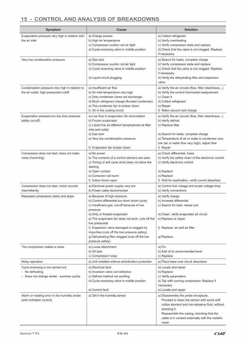
Vect ios TM PJ EN-64
15 - CONTROL AND ANALYSIS OF BREAKDOWNS
Symptom Cause Solution
Evaporation pressure very high in relation with the air inlet
a) Charge excessb) High air temperaturec) Compressor suction not air tightd) Cycle reversing valve in middle position
a) Collect refrigerantb) Verify overheatingc) Verify compressor state and replaced) Check that the valve is not clogged. Replace if necessary
Very low condensation pressure a) Gas lackb) Compressor suction not air tightc) Cycle reversing valve in middle position
d) Liquid circuit plugging
a) Search for leaks, complete chargeb) Verify compressor state and replacec) Check that the valve is not clogged. Replace if necessaryd) Verify the dehydrating fi lter and expansion valve
Condensation pressure very high in relation to the air outlet, high pressostat cutoff
a) Insuffi cient air fl owb) Air inlet temperature very highc) Dirty condenser (does not exchange)d) Much refrigerant charge (fl ooded condenser)e) The condenser fan is broken downf) Air in the cooling circuit
a) Verify the air circuits (fl ow, fi lter cleanliness...)b) Verify the control thermostat readjustmentc) Clean itd) Collect refrigerante) Repairf) Make vacuum and charge
Evaporation pressure too low (low pressure safety cut-off)
a) Low fl ow in evaporator. Air recirculationb) Frozen evaporatorc) Liquid line as different temperatures at fi lter inlet and outletd) Gas lacke) Very low condensation pressure
f) Evaporator fan broken down
a) Verify the air circuits (fl ow, fi lter cleanliness...)b) Verify defrostc) Replace fi lter
d) Search for leaks, complete chargee) Temperature of air or water in condenser very low (air or water fl ow very high), adjust fl owf) Repair
Compressor does not start, does not make noise (humming)
a) No powerb) The contacts of a control element are openc) Timing of anti cycle short does not allow the startingd) Open contacte) Contactor coil burntf) Indoor klixon open
a) Check differential, fusesb) Verify the safety chain of the electronic controlc) Verify electronic control
d) Replacee) Replacef) Wait for reactivation, verify current absorbed
Compressor does not start, motor sounds intermittently
a) Electrical power supply very lowb) Power cable disconnected
a) Control line voltage and locate voltage drop b) Verify connections
Repeated compressor starts and stops a) Because of high pressureb) Control differential too short (short cycle)c) Insuffi cient gas, cut-off because of low pressured) Dirty or frosted evaporatore) The evaporator fan does not work, cuts off the low pressostatf) Expansion valve damaged or clogged by impurities (cuts off the low pressure safety)g) Dehydrating fi lter clogged (cuts off the low pressure safety)
a) Verify chargeb) Increase differentialc) Search for leak, reload unit
d) Clean, verify evaporator air circuite) Replace or repair
f) Replace, as well as fi lter
g) Replace
The compressor makes a noise a) Loose attachmentb) Oil lackc) Compressor noise
a) Fixb) Add oil to recommended levelc) Replace
Noisy operation a) Unit installed without antivibration protection a) Place base over shock absorbers
Cycle reversing is not carried out:- No defrosting- Does not change winter - summer cycles
a) Electrical faultb) Inversion valve coil defectivec) Defrost method not workingd) Cycle reversing valve in middle position
e) Control fault
a) Locate and repairb) Replacec) Verify parametersd) Tap with running compressor. Replace if necessarye) Locate and repair
Alarm or reading error in the humidity probe (with enthalpic control)
a) Dirt in the humidity sensor a) Disassembly the probe encapsule.Proceed to clean the sensor with some soft cotton element and non-abrasive fl uid, without pressing it. Reassemble the casing, checking that the cable is in contact externally with the metallic mesh.

Vect ios TM PJEN-65
16 - FINAL SHUTDOWN
16.1 Shutting down
Separate the units from their energy sources, allow them to cool then drain them completely.
16.2 Recommendations for disassembly
Use the original lifting equipment.
Sort the components according to their material for recycling or disposal, in accordance with regulations in force.
Check whether any part of the unit can be recycled for another purpose
16.3 Fluids to be recovered for treatment
● Refrigerant
● Energy transfer fl uid: depending on the installation, water, glycol/water mix.
● Compressor oil
Important: In order to recycle these units follow the stipulations of Directive 2012/19/EU on Waste electrical and electronic equipment (WEEE).
16.4 Materials to be recovered for recycling
● Steel● Copper● Aluminium● Plastics● Polyurethane foam (insulation)
16.5 Waste electrical and electronic equipment (WEEE)
At the end of its life, this equipment must be disassembled and contaminated fl uids removed by professionals and processed via approved channels for electrical and electronic equipment (WEEE).

Vect ios TM PJ EN-66
Notes: