Piling Specification to BS5400
25
B/1 Piling Work SECTION B.1 - GENERAL REQUIREMENTS 1. General 1.1 Unless otherwise specified , all piling shall conform in all respects to BS 8004. Allmaterials and workmanship for piling shall be in accordance with the appropriate sections of this Specification. 2. Soil Investigation Reports 2.1 Any information and report on soil investigatio n for the Works made available to tenderers are intended for guidance only. The S.O. shall not be responsible for the scope,completeness or accuracy of the information, or for any opinion or conclusion given in the report. 3. Tolerances 3.1 Setting out Setting out shall be carried out from the main grid lines of the proposed structure.I mmediately before installation of the pile, the pile position shall be marked with suitable identifiable pins, pegs or markers. 3.2 Position For a pile cut-off at or above ground level, the maximum permitted deviation of the pile centre from the centre points shown in the Drawings shall not exceed 75mm in any direction. For a pile cut off below ground level, an increase in this tolerance is permitted in accordance with clauses 3.3 and 3.4 herein below. 3.3 Verticality The maximum permitted deviation of the finished pile from the vertical shall be 1 in 75. 3.4 Rake The piling rig shall be set and maintained to attain the required rake. The maximum permitted deviation of the finished pile from the specified rake or the rake shown in the Drawings shall be 1 in 25. 3.5 Forcible correction Forcible correction to concrete piles shall not be permitted. Forcible corrections may be permitted to other types of piles only if approved by the S.O. However, no forcible correction shall be made to piles which have deviated beyond the permissible limits specified in clauses 3.2, 3.3 and 3.4. 3.6 Piles out of Alignment or Position The Contractor shall, if ordered by the S.O., extract and reinstall any pile which has deviated out of position or alignment by more than the specified limit, or alternatively the substructure shall be modified to the approval of the S.O. The cost of such extraction and reinstallation, or any extra cost in the design and construction of a modified foundation shall be borne by the Contractor, if, in the opinion of the S.O., such B/2 Piling Work
-
Upload
atiq-zakaria -
Category
Documents
-
view
239 -
download
1
Transcript of Piling Specification to BS5400
7/28/2019 Piling Specification to BS5400
http://slidepdf.com/reader/full/piling-specification-to-bs5400 1/25
B/1Piling Work SECTION B.1 - GENERAL REQUIREMENTS
1. General
1.1 Unless otherwise specified, all piling shall conform in all respects to BS 8004. Allmaterials
and workmanship for piling shall be in accordance with the appropriate sections of thisSpecification.
2. Soil Investigation Reports
2.1 Any information and report on soil investigation for the Works made available to tenderersare intended for guidance only. The S.O. shall not be responsible for the scope,completenessor accuracy of the information, or for any opinion or conclusion given in the report.
3. Tolerances3.1 Setting outSetting out shall be carried out from the main grid lines of the proposed structure.Immediately
before installation of the pile, the pile position shall be marked with suitable identifiable pins,pegs or markers.
3.2 PositionFor a pile cut-off at or above ground level, the maximum permitted deviation of the pile centrefrom the centre points shown in the Drawings shall not exceed 75mm in any direction. For apile cut off below ground level, an increase in this tolerance is permitted in accordance withclauses 3.3 and 3.4 herein below.
3.3 VerticalityThe maximum permitted deviation of the finished pile from the vertical shall be 1 in 75.
3.4 RakeThe piling rig shall be set and maintained to attain the required rake. The maximum permitteddeviation of the finished pile from the specified rake or the rake shown in the Drawings shallbe 1 in 25.
3.5 Forcible correctionForcible correction to concrete piles shall not be permitted. Forcible corrections may bepermitted to other types of piles only if approved by the S.O. However, no forcible correctionshall be made to piles which have deviated beyond the permissible limits specified in clauses3.2, 3.3 and 3.4.
3.6 Piles out of Alignment or Position
The Contractor shall, if ordered by the S.O., extract and reinstall any pile which has deviatedout of position or alignment by more than the specified limit, or alternatively the substructureshall be modified to the approval of the S.O. The cost of such extraction and reinstallation, orany extra cost in the design and construction of a modified foundation shall be borne by theContractor, if, in the opinion of the S.O., such
B/2Piling Work

7/28/2019 Piling Specification to BS5400
http://slidepdf.com/reader/full/piling-specification-to-bs5400 2/25
extra work has beenmade necessary due to the incompetency and/or negligence of theContractor.
4. Piling Programme4.1 The Contractor shall submit to the S.O. his proposed programme for the execution of thepiling work at least seven (7) days before commencement of the Work. In addition, the
Contractor shall inform the S.O. daily of the programme of piling for the following working dayand shall give adequate notice of his intention to work outside working hours, if this hasalready been approved by the S.O.
5. Records5.1 The Contractor shall keep records of particulars as listed in Table 1 hereof for eachpileinstalled, and shall submit two (2) signed copies of these records to the S.O. not later thannoon of the next working day after the pile was installed. The signed records shall form part ofthe records for the Works.
5.2 Any unexpected driving condition shall be noted in the records.
6. Nuisance and Damage6.1 Noise and DisturbanceThe Contractor shall take all necessary precaution in carrying out the work so as to minimisenoise and disturbance during driving.
6.2 Damage to Adjacent Structures, Utilities6.2.1 The Contractor's attention is specially drawn to his responsibilities under theclause ‘Damage to Property’ of the Conditions of Contract. The Contractor is deemedto have familiarised himself with the risks likely to be imposed on adjacent structuresand all utilities by the proposed method of piling.6.2.2 Before commencing any piling work, the Contractor shall accompany the S.O. ona site inspection in order to consider any circumstances which may indicate
thepresence of underground mains and services at or in the vicinity of the Site.If,during execution of the Work, damage is or is likely to be caused to any utilities oradjacent structures, the Contractor shall submit to the S.O. his proposals for repair oravoidance of such damage.
7. Damage to Piles7.1 The Contractor shall execute the Work in such a manner so as to minimise damage topiles.
7.2 All piles damaged during handling, transporting, pitching, driving or at any other time shallbe replaced by the Contractor at his own expense.
8. Safety Precautions8.1 The Contractor shall take safety precautions throughout the piling operation in accordancewith the requirements of the relevant laws and by-laws.B/3Piling Work9. Definition
9.1 Preliminary Pile

7/28/2019 Piling Specification to BS5400
http://slidepdf.com/reader/full/piling-specification-to-bs5400 3/25
A preliminary pile is a pile installed before the commencement of the main piling work forthepurpose of establishing the driving criteria for subsequent working piles and for confirming theadequacy of the design, dimensions and bearing capacity. This pile shall be treated as aworking pile unless otherwise directed by the S.O.
9.2 Working Pile
A working pile is a pile which is installed as part of the permanent foundation work.
9.3 Ultimate Load9.3.1 Where pile test is carried out, the Ultimate Load is defined as the constant loadat which the pile continues to settle at a steady rate, or the load at which the maximumsettlement of the pile during one continuous loading cycle is one tenth of the pile basediameter or least dimension, whichever is the lesser.
9.3.2 Where a pile test is not carried out, the Ultimate Load is defined as the calculatedUltimate Load, derived from appropriate static bearing capacity calculations.
9.4 Design Load
9.4.1 The Design Load shall be defined in relation to a pile loaded in isolation, withoutnearby piles being loaded, except those providing test reaction.
9.4.2 Where the Ultimate Load is measured by means of pile tests, the Design Load isthe Ultimate Load divided by the specified factor of safety.
9.4.3 Where the Ultimate Load is not measured by means of pile tests, the DesignLoad is the lesser of the following:-
(a) the calculated ultimate load for the pile divided by the specified factor ofsafety
(b) the calculated ultimate load of the pile base together with the calculatedshaft adhesion, as derived from appropriate static bearing capacitycalculations, divided by a factor of safety of 3.0.
9.5 Factor of SafetyUnless otherwise stated in the Drawings, the Factor of Safety shall be taken as not less than2.0 for piles in compression, and not less than 3.0 for piles in tension.
9.6 Working LoadThe Working Load is the Design Load modified to allow for group effect, pile spacing or anyother factors changing the efficiency of the total foundation from that of a single isolated pile,and is at least equal to the dead plus imposed loads on the pile together with downdrag or
uplift loads as appropriate.
7/28/2019 Piling Specification to BS5400
http://slidepdf.com/reader/full/piling-specification-to-bs5400 4/25
B/4Piling Work
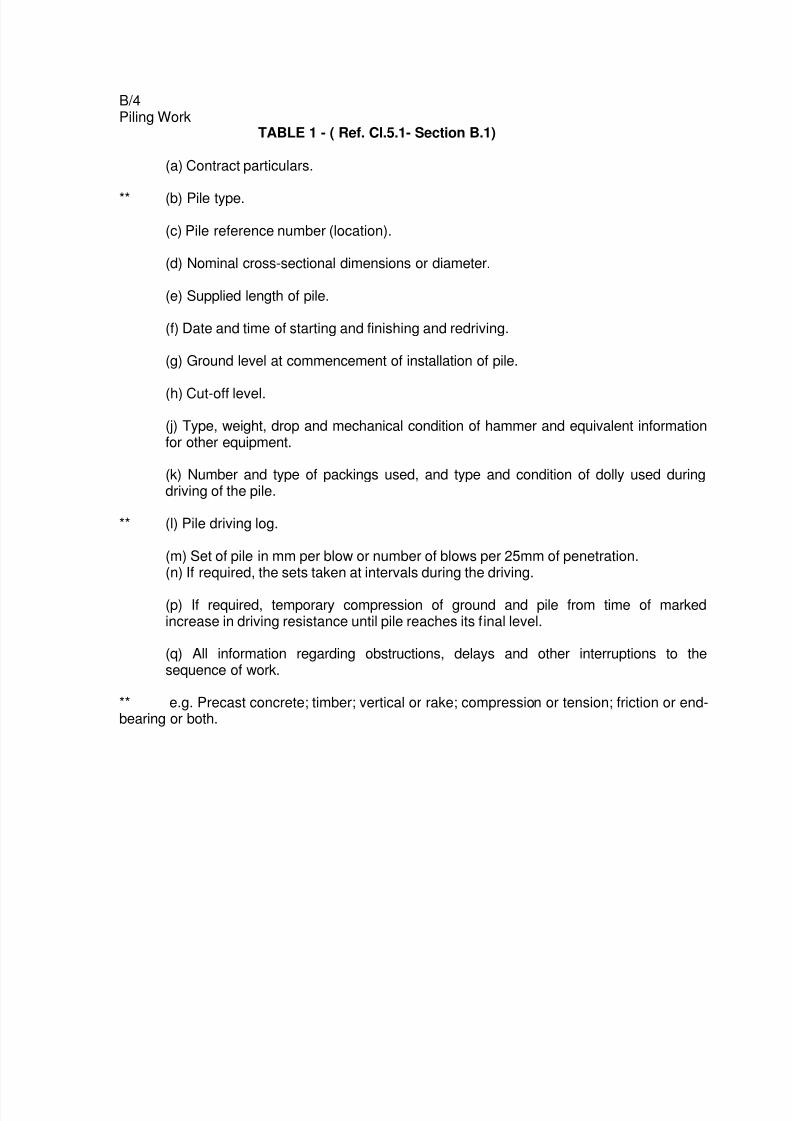
TABLE 1 - ( Ref. Cl.5.1- Section B.1)
(a) Contract particulars.
** (b) Pile type.
(c) Pile reference number (location).
(d) Nominal cross-sectional dimensions or diameter.
(e) Supplied length of pile.
(f) Date and time of starting and finishing and redriving.
(g) Ground level at commencement of installation of pile.
(h) Cut-off level.
(j) Type, weight, drop and mechanical condition of hammer and equivalent informationfor other equipment.
(k) Number and type of packings used, and type and condition of dolly used duringdriving of the pile.
** (l) Pile driving log.
(m) Set of pile in mm per blow or number of blows per 25mm of penetration.(n) If required, the sets taken at intervals during the driving.
(p) If required, temporary compression of ground and pile from time of markedincrease in driving resistance until pile reaches its final level.
(q) All information regarding obstructions, delays and other interruptions to thesequence of work.
** e.g. Precast concrete; timber; vertical or rake; compression or tension; friction or end-bearing or both.
7/28/2019 Piling Specification to BS5400
http://slidepdf.com/reader/full/piling-specification-to-bs5400 5/25
7/28/2019 Piling Specification to BS5400
http://slidepdf.com/reader/full/piling-specification-to-bs5400 6/25
B/6Piling Work
6. Marking, Handling and Storage of Piles6.1 After a pile has been cast, the date of casting, reference number, and the length shall beclearly marked with indeletable marker on the top surface and on the head of the pile. In
addition, each pile shall be marked at intervals of 300mm along its length before being driven.
6.2 The method and sequence of lifting, handling, transporting and storing piles shall be suchthat piles are not damaged. Only the designed lifting and support points shall be used. Duringtransport and storage, piles shall be placed on adequate supports located under the liftingpoints of the piles.
6.3 All piles within a stack shall be in groups of the same length. Packings of uniformthickness shall be provided between piles at the lifting points.
7. Tolerances in Pile Dimensions7.1 The cross-sectional dimensions of the pile shall not be less than those shown in the
Drawings, and shall not exceed them by more than 6mm.
7.2 Any face of a pile shall not deviate by more than 6mm from a straight edge 3m long laid onthe face, and the centroid of any cross-section of the pile shall not deviate by more than12mm from the straight line connecting the centroids of the end faces of the pile.
8. Length of Piles8.1 The length of a pile shall be taken to mean the overall length measured from the tip of theshoe to the top of the head. The length of piles shall be to the approval of the S.O. Based onthe results of pile driving resistance and/or load tests carried out on piles driven on the Site,the S.O. may, from time to time, order the lengths of piles to be modified.
9. Pitching and Driving9.1 Driving EquipmentThe driving equipment to be used shall be of such type and capacity to the approval of theS.O. If a drop hammer is used, it shall be of a free fall type, and the weight of the hammershall be as specified in BS 8004. For driving piles of sizes smaller than 200mm, dieselhammer shall not be used.
9.2 Pitching of PilesPiles shall be pitched accurately in the positions as shown in the Drawings. At all stagesduring driving and until the pile has set or been driven to the required length, all exposed pilesshall be adequately supported and restrained by means of leaders, trestles, temporarysupports or other guide arrangements to maintain position and alignment, and to prevent
buckling and damage to the piles.
9.3 Driving of Piles9.3.1 Each pile shall be driven continuously until the specified set and/or depth hasbeen reached. However, the S.O. may permit the suspension of driving if he issatisfied that:
7/28/2019 Piling Specification to BS5400
http://slidepdf.com/reader/full/piling-specification-to-bs5400 7/25
B/7Piling Work
a) the rate of penetration prior to the cessation of driving will be substantiallyre-established on its resumption, or
b) the suspension of driving is beyond the control of the Contractor.9.3.2 A follower (long dolly) shall not be used for driving end bearing piles. It may be
used for driving frictional piles with the prior approval of the S.O.9.3.3 The Contractor shall inform the S.O. without delay if an unexpected change indriving characteristics is encountered.9.3.4 Where required by the S.O., the set shall be taken at approved intervals duringthe driving to establish the behaviour of the piles. A set shall be taken only in thepresence of the S.O. unless otherwise approved. The Contractor shall provide allfacilities to enable the S.O. to check driving resistance.9.3.5 Redrive checks, if required, shall be carried out in accordance with an approvedprocedure.
9.4 Pile Driving LogA detailed record of the driving resistance over the full length of each pile shall be
kept.The log shall record the number of blows for every 300mm of pile penetration.
9.5 Final Set9.5.1 The final set of a pile other than a friction pile, shall be recorded either asthe penetration in millimetres per 10 blows or as the number of blows requiredto produce a penetration of 25mm.9.5.2 When a final set is being measured, the following requirements shall bemet:-a) The exposed part of the pile shall be in good condition, without damage ordistortion;b) The dolly and packing shall be in sound condition;c) The hammer blow shall be in line with the pile axis, and the impactsurfaces
shall be flat and at right angles to the pile and hammer axis;d) The hammer shall be in good condition and operating correctly;e) The temporary compression of the pile shall be recorded.
9.6 Driving Sequence and Risen PilesPiles shall be driven in an approved sequence to minimise the detrimental effects of heaveand lateral displacement of the ground. When required, levels and measurements shall betaken to determine the movement of the ground or any pile resulting from the driving process.If any pile rise occurs as a result of adjacent piles being driven, the Contractor shall submit tothe S.O. his proposals for correcting this and to avoid the same in subsequent work.
9.7 Preboring
If preboring is specified, the pile shall be pitched into a hole prebored to the depth shown inthe Drawings, unless otherwise instructed by the S.O.
9.8 JettingJetting shall be carried out only when the Contractor’s detailed proposals have beenapproved, and not for the last 3 metre of the required depth of penetration.B/8Piling Work
7/28/2019 Piling Specification to BS5400
http://slidepdf.com/reader/full/piling-specification-to-bs5400 8/25
10. Repair and Lengthening of Pile10.1 Repair of Damaged Pile Heads
10.1.1 Damaged pile head shall be cut off square at sound concrete, and alllooseparticles shall be removed by wire brushing, followed by washing with water. Ifthepile is to be subjected to further driving, the head shall be replaced with concrete of anapproved grade. The new head shall be cast truly in line with the remainder of the pile,
and be properly cured and allowed to harden sufficiently to develop the strengthnecessary for further driving.10.1.2 If a pile has been driven to the required set or depth but sound concrete of thepile is below cut-off level, the pile shall be made good to the cut-off level with concreteof a grade not inferior than that of the concrete of the pile.
10.2 Lengthening of PilesWhere piles have to be lengthened, other than by means of welding of steel plates as detailedin the Drawings, the reinforcement shall be stripped of all surrounding concrete for a distanceequal to 40 times the diameter of the main reinforcement measured from the pile head forspliced joints and 300mm for butt welded joints, and all lateral reinforcement shall beremoved. The lengthening bars shall butt on the exposed bars in true alignment, and shall be
butt welded as specified or shall be spliced with bars of the same diameters as the main pilebars, 80 times diameter in length and lapping the main bars for a distance of 40 timesdiameter above and below the joint, and shall be securely bound with 1.63mm soft annealediron wire. New binders of similar size shall be provided and spaced at half the centres of thebinders in the main body of the pile, and shall be securely bound with 1.63mm diameter softannealed iron wire, and the pile extended by concreting in properly constructed mounds to thelength required. Steps shall be taken to ensure that the concrete at the joint between the oldand the new concrete is not of inferior grade and quality than that of the concrete of the pile.The extension shall be truly in line with the remainder of the pile, and be properly cured andallowed to harden sufficiently to develop the strength necessary for further driving.
10.3 Driving Repaired/Lengthened Piles
Piles which have been repaired or lengthened by adding cast-insitu concrete as specified inclauses 10.1 and 10.2 shall not be driven until the added concrete has reached the specifiedstrength of the concrete for the pile.
11. Cutting and Stripping of Pile Heads11.1 When a pile has been driven to the required set or depth, the head of the pile shall be cutoff to the level shown in the Drawings or as instructed by the S.O. The length of reinforcingbars projecting above this level shall be as shown in the Drawings.
11.2 Care shall be taken to avoid cracking or otherwise damaging the rest of the pile. Crackedor defective concrete shall be cut away and made good with new concrete properly bonded tothe old.

7/28/2019 Piling Specification to BS5400
http://slidepdf.com/reader/full/piling-specification-to-bs5400 9/25
B/9Piling Work
SECTION B.3 - STEEL H-BEARING PILES
1. Pile Sections and Dimensions
1.1 All steel H-bearing piles shall comply with JIS A5526 with regards to profile andtolerances and the steel shall comply with the requirements of BS EN 10025 and BS 4360.The profile and grade to be used are as specified or as shown in the Drawings.
2. Straightness of Piles
2.1 For standard rolled profiles, the deviation from straightness in millimetres shall not exceed1.04(L-4.5) where L is the length of the pile in metres.2.2 For proprietary sections made upfrom rolled profiles, the deviation from straightness shall not exceed 1/1000 of the length ofthe pile.
3. Strengthening of Piles
3.1 Unless otherwise approved by the S.O., the strengthening of the toe of the pile in lieu of ashoe or the strengthening of the head of a pile shall be made from material of the same gradeas the pile and to the details as shown in the Drawings.
4. Marking of Piles
4.1 Each pile shall be clearly marked with white indeletable marking at the flanged headshowing its reference number and overall length. In addition, each pile shall be markedat intervals of 300mm along its length before being driven.
5. Handling and Storage of Piles
5.1 All operations such as handling and transporting of piles shall be carried out in such amanner that damage to piles and their coatings are minimised. Piles that are damagedduring handling and transporting shall be replaced by the Contractor at his ownexpense. All damaged and rejected piles shall be removed from the Site forthwith. 5.2Piles within a stack shall be in groups of the same length and on approved supports.
6. Pitching and Driving of Piles
6.1 Pitching and driving of piles shall be in accordance with Clauses 9.1 to 9.8 as specifiedhereinbefore under ‘PRECAST REINFORCED CONCRETE PILES’.
7. Lengthening of Piles
7.1 Where lengthening of piles are required, the piles shall be jointed by butt-welding,stiffened with plates fillet-welded on all four sides as detailed in the Drawings. Allwelding shall be continuous and complying with BS 5135 and BS 5950. The type andsize of welding shall be as detailed in the Drawings.

7/28/2019 Piling Specification to BS5400
http://slidepdf.com/reader/full/piling-specification-to-bs5400 10/25
B/10Piling Work
8. Preparation of Pile Heads8.1 When a pile has been driven to the required set or depth and before encasing in concrete,the piles shall be cut to within 20mm of the levels shown in the Drawings, and protective
coatings, if any, shall be removed from the surfaces of the pile heads down to a level 150mmabove the soffit of the concrete. Pile heads shall be constructed to the details as shown in theDrawings.

7/28/2019 Piling Specification to BS5400
http://slidepdf.com/reader/full/piling-specification-to-bs5400 11/25
B/11Piling Work
SECTION B.4 - PRESSURE -TREATED TIMBER PILES1. Timber
1.1 GeneralPressure-treated timber piles to be used for the Works shall be those approved by SIRIM.
1.2 Species of timberUnless otherwise approved by the S.O., only Kempas (Kempassia Malaccensis) shall beused.
1.3 DefinitionsThe timber terms used in the Specification shall have the meaning assigned to them in BS5268 or the Malayan Grading Rules for Sawn Hardwood Timber (1968) whichever isapplicable.
1.4 QualityTimber used for the piles shall not be of a lesser quality than the Selected Structural GradesSpecified in Section J (Stress Grading) of Part III of the Malayan Grading Rules for SawnHardwood Timber. The timber shall be free from rot, fungal or pest attack, and any otherdefects not permitted for its grade.
1.5 Tolerances in DimensionThe dimension of sawn timber piles shall be within the range of 2mm less and 6mm greaterthan their specified cross-sectional dimensions. The centroid of any cross-section of a sawntimber pile shall not deviate by more than 25mm from the straight line connecting thecentroids of the end faces of the standard length of a 6 metre pile.
2. Workmanship
2.1 Where applicable, the standard of workmanship shall conform to BS 5268.
3. Preservative Treatment
3.1 The method for treatment of timber shall be the full-cell process. The full-cell process,compositions of preservatives, the test methods for determining the depth of penetration ofpreservatives, and the weight of net salt retention in the treated timber shall be as described inMS 1302, MS 1304 and MS 360. The minimum depth of penetration of preservative shall be25mm and the minimum weight net dry salt retention in the treated part of the timber shall notbe less than 16 kg/m3.
4. Marking of Pile
4.1 The treated pile shall be permanently marked with identifications which indicate that theycomply with this Specification, manufacturer’s trade mark, charge number and date oftreatment and the length of the pile.
7/28/2019 Piling Specification to BS5400
http://slidepdf.com/reader/full/piling-specification-to-bs5400 12/25
B/12Piling Work5. Inspection5.2 The S.O. may require inspection of the treatment plant to observe and ensure that themanufacturing process and control testings of the piles are carried out in accordance with thisSpecification. Records of the actual treatment schedule shall be kept during the treatment
process, and the Contractor shall furnish such records for the piles supplied when requestedby the S.O.
6. Warranty6.1 Before commencement of work, the Contractor shall notify the S.O. the name of thesupplier and manufacturer for approval.6.2 Before the treated timber pile is accepted for the work, the Contractor shall obtain from themanufacturer of the treated piles, a warranty on an approved form, which provides that thetreated piles shall be free from such fungus and insect attack which may render the supportedbuilding structurally unsound, for a thirty (30) years period.
7. Delivery and Stacking
7.1 The Contractor shall notify the S.O. of the delivery of timber piles to the Site and providethe necessary facilities to enable the S.O. to inspect each pile and take random sampling fordetermination of depth of penetration and the net dry salt retention.7.2 Accepted piles shall be marked and stacked in lengths on levelled and well-drained hardground. Each pile shall be stacked clear off the ground with an air space around it. The pilesshall be separated by sticks or blocks placed vertically one above the other and closelyspaced horizontally to avoid sagging of the piles. All rejected piles shall be removed from theSite promptly.
8. Pile Head8.1 The pile head shall be adequately protected during driving so that brooming does notoccur.
8.2 The pile head shall be fitted with toothed metal plates as approved by the S.O. forprotection against brooming and splitting during normal driving.8.3 In the case of hard driving, unless otherwise approved by the S.O., a metal helmet shallbe fitted to the top of the pile. The top of the pile shall first be trimmed to fit closely into therecess of the underside of the helmet. A hard timber dolly and, if necessary, a packing pieceshall be used above the helmet.8.4 If during driving, the head of the pile becomes excessively broomed or otherwisedamaged, the damaged part shall be cut off and the helmet refitted.
9. Pitching and Driving of Piles9.1 Pitching and driving of piles shall be in accordance with clauses 9.1 to 9.8 as describedhereinbefore under ‘PRECAST REINFORCED CONCRETE PILES’.
10. Lengthening of Piles10.1 Piles shall be provided in one single length of 6.0m each, unless otherwise approved.Any pile driven to the required set at a depth of 6.0m or less shall be in one continuous length.
7/28/2019 Piling Specification to BS5400
http://slidepdf.com/reader/full/piling-specification-to-bs5400 13/25
B/13Piling Work
10.2 If jointing is required, pile joints shall be made by using mild steel welded boxes, 450mmlong, fabricated from 5mm thick plates, unless otherwise shown in the Drawings. The internaldimensions of the box shall be 3mm undersize of the pile cross-sectional dimensions. The
joint and the ends of the piles to be jointed shall be constructed so that the necessary strengthand stiffness are developed at the joint.
11. Defects on Piles while Driving11.1 When fissures appear in a pile during driving, which, in the opinion of the S.O., will affectits strength, the pile shall be rejected and replaced at the Contractor’s expense.
12. Preparation of Pile Heads12.1 When a pile has been driven to the required set or depth, the head of the piles shall becut off square to sound wood and treated with an approved preservative and a waterproofcoating to the approval of the S.O.12.2 The pile head shall be embedded for a depth of not less than 150mm in the concrete
cap, with a minimum of 150mm concrete surround.
7/28/2019 Piling Specification to BS5400
http://slidepdf.com/reader/full/piling-specification-to-bs5400 14/25
B/14Piling Work
SECTION B.5 - PILE TESTING1. General1.1 Type of Tests NecessaryThe Maintained Load Test shall be carried out on a test pile. The Contractor shall, if required
by the S.O., carry out the Constant Rate of Penetration Test on completion of the MaintainedLoad Test.
1.2 Safety PrecautionsWhen preparing, conducting and dismantling a pile test, the Contractor shall carry out thework in a safe manner, and shall in addition make such other provisions, as may benecessary, to safeguard against any likely hazards.
2. Definitions2.1 Compression PileA pile which is designed to resist an axial force such as would cause it to penetrate into theground.
2.2 Anchor PileA pile which is designed to resist an axial force such as would tend to cause it to be extractedfrom the ground.
2.3 Test PileA compression pile to which a load is applied to determine the load versus settlementcharacteristics of the pile and the surrounding ground.
2.4 Reaction SystemThe system of kentledge, piles or anchors that provides resistance against which the pile istested.
2.5 KentledgeThe dead weight used in a loading test.
2.6 Maintained Load TestA loading test in which each increment or decrement of load is held constant either for adefined period of time or until the rate of settlement or rebound falls to a specified value.
2.7 Constant Rate of Penetration Test (CRP)A loading test in which the pile is made to penetrate the soil from its position at a constantspeed while the force applied at the top of the pile to maintain the rate of penetration iscontinuously measured, until the force versus penetration relationship obtained does not
represent an equilibrium condition between load and settlement.
3. Supervision3.1 All tests shall be carried out only under the direction of an experienced and competentContractor's supervisor, with approved test equipment and test procedure as specifiedhereinafterB/15Piling Work

7/28/2019 Piling Specification to BS5400
http://slidepdf.com/reader/full/piling-specification-to-bs5400 15/25
3.2 All Contractor's personnel operating the test equipment shall have been trained in itsuse.Tests shall be carried out only in the presence of the S.O. or the S.O’s representative.
4. Reaction System4.1 GeneralCompression test shall be carried out using a kentledge, anchor piles or specially constructed
anchorages as reaction system. The reaction system used shall be designed to transfer safelyto the test pile the maximum load required for testing. Full details of the reaction system shallbe submitted to the S.O. prior to any work related to the testing process being carried out onthe Site.
4.2 KentledgeWhere kentledge is to be used, it shall have adequate weight to resist load up to 1.2 times themaximum test load. The kentledge shall be supported on cribwork, beams or other supportingstructure disposed around the test pile so that its centre of gravity is on the axis of the pile.Kentledge shall not rest directly on the pile head. The bearing pressure under the supportsshall be such as to ensure stability of the kentledge stack and shall not impair the efficiency ofthe testing operations. The distance from the edge of the test pile to the nearest part of the
supports to the kentledge stack in contact with the ground shall not be less than 1.3m.
4.3 Anchor Pile and Ground Anchor4.3.1 Where anchor piles or ground anchors are to be used, they shall be of adequatestrength to resist load up to 1.2 times the maximum test load on the ground, in a safe mannerwithout excessive movement or influence on the test pile. The method employed in theinstallation shall be such to prevent damage to any test pile or working pile.
4.3.2 The Contractor shall ensure that when the test load is applied, the load is correctlytransmitted to all the bolts and tie rods. The extension of rods by welding shall not bepermitted, unless it is known that the steel will not be reduced in strength by welding. Thebond stress of the rods in tension shall not exceed normal permissible bond stresses of the
type of steel and grade of concrete used.
4.3.3 Where anchor piles are used, the centre to centre spacing of these piles from a test pileshall be not less than three (3) times the diameter of the test pile, or the anchor piles, or 2m,whichever is the greater. Under-reamed piles shall not be used as anchor piles. Wherepermanent working piles are approved by the S.O. to be used as anchor piles, their levelsshall be observed during application of the test load to ensure that there is no residual uplift.
4.3.4 Where ground anchors are used, no part of the section of the anchor transferring load tothe ground shall be closer to the test pile than three (3) times the diameter of the test pile.Furthermore, no part of the ground anchor shall be closer to a working pile than one-and-a-half times the diameter of the test pile along the unbonded length of the anchor, and three (3)
times the diameter of the test pile along the bonded length of the anchor. Under-reams onground anchors shall not exceed 170mm in diameter.
7/28/2019 Piling Specification to BS5400
http://slidepdf.com/reader/full/piling-specification-to-bs5400 16/25
B/16Piling Work
5. Testing Equipment
5.1 The Contractor shall ensure that when the hydraulic jack and load measuring device are
mounted on the pile heads, the whole system will be stable up to the maximum load to beapplied.5.2 The test loads shall be applied by means of a hydraulic jack of adequate capacity, fittedwith a load measuring device.5.3 The hydraulic jack, pump, hoses, pipes, couplings and other apparatus to be operatedunder hydraulic pressure, shall be capable of withstanding a test pressure equivalent to oneand a half (1½) times the maximum test load without leakage.5.4 Where the C.R.P. test is required, the jack pump capacity shall be adequate to maintainthe required rate of penetration. The permissible extension of the jack shall be such that thepile can be moved continuously and without repacking for a distance of at least 50mm.5.5 The measuring device shall be of the type approved by the S.O., capable of registeringloads in increments not exceeding 20 KN.
5.6 The hydraulic jack and measuring device shall be calibrated together to the approval ofthe S.O. before and after each series of tests, whenever adjustments are made to the deviceor at intervals appropriate for the type of equipment used. Certificates of calibration shall besubmitted to the S.O.5.7 The loading equipment shall be capable of adjustment throughout the test to obtain asmooth increase of load or to maintain each load constant at the required stages of themaintained load test.
6. Preparation of a Working Pile to be Tested
6.1 GeneralIf a test is required on a working pile, the Contractor shall prepare the pile for testing to the
approval of the S.O.6.2 Driving RecordsFor each working pile which is to be tested, a detailed record of driving shall be made andsubmitted to the S.O. daily, not later than noon on the next working day.6.3 Cut-off LevelThe pile shall terminate at the normal cut-off level or at a level required by the S.O. However,where necessary, the pile shall be extended above the cut-off level of working piles so thatgauges and other apparatus to be used in the testing process will not be damaged by water orfalling debris. If the cut-off level is below ground level, the pile is not extended and there is arisk of the borehole collapsing, a sleeve shall be left in place or inserted above the pile, orother approved action shall be taken. Adequate clearance shall be given between the top ofthe pile and the bottom of the sleeves to permit unrestricted movement of the pile. 6.4 Pile
Head for Compression Test For pile that is tested in compression, the pile head or cap shallbe formed to give a plane surface which is normal to the axis of the pile. An approved mildsteel bearing plate shall be mounted on top of the pile head or cap to accommodate theloading and settlement measuring equipment, and to prevent damage from the concentratedapplication of load from the loading equipment.
7/28/2019 Piling Specification to BS5400
http://slidepdf.com/reader/full/piling-specification-to-bs5400 17/25
B/17Piling Work
6.5 Notice of TestThe Contractor shall give the S.O. at least 24 hours notice of the commencement of test.
7. Settlement Measurement
7.1 An independent reference frame shall be set up to permit measurement of the verticalmovement of the test pile. The support for the frame shall be located not closer than 2 metresfrom the test pile, and shall be rigidly fixed to the ground to a depth of not less than 1m withconcrete surround. In addition, the elevation of the supports shall be checked frequently withreference to a fixed benchmark.7.2 The entire measuring assembly shall be protected against rain, direct sunlight and otherdisturbances that might affect its reliability. Temperature readings shall be taken whenrequested by the S.O. The measurement of pile movement shall be made by four dial gaugesrigidly mounted on the reference frame that bear on machined metal or glass surfaces, normalto the pile axis fixed to the pile cap or head. Alternatively, the gauges may be fixed to the pile
and bear on surfaces on the reference frame. The dial gauges shall be placed in diametricallyopposite positions, and be equidistant from the pile axis. The dial gauges shall enablereadings to be made to within an accuracy of 0.1mm, and shall have a minimum travel of notless than 50mm.7.3 The Contractor may submit other methods of measuring the movement of pile heads forapproval.
8. Test Procedure8.1 GeneralThroughout the test period, all equipment for measuring load and movement shall beprotected from the effects of weather. Construction equipment and persons who are notinvolved in the testing process shall be kept at a sufficient distance from the test to avoid
disturbance to the measurement apparatus.
8.2 Maintained Load Test8.2.1 The load shall be applied in increment of 25% of the working load, up to theworking load and appropriately smaller thereafter, until a maximum test load of twicethe working load is reached. Each increment of load shall be applied as smoothly andas expeditiously as possible. Settlement readings and time observations shall be takenbefore and after each new load increment.8.2.2 A time-settlement graph shall be plotted to indicate when the rate of settlement of0.05mm in 15 minutes is reached. A further increment of load shall be applied whenthis rate of settlement is achieved, or until a minimum time of 2 hours has elapsed,whichever is later. The process shall be repeated until the maximum test load is
reached.8.2.3 The maximum test load shall then be maintained for a minimum of 24 hours, andtime-settlement readings shall be taken at regular intervals, as for the earlier loadstages.8.2.4 The test load shall then be decreased in four equal stages, and time-settlementreadings shall be as specified aforesaid, until the movement ceases. At least 60

7/28/2019 Piling Specification to BS5400
http://slidepdf.com/reader/full/piling-specification-to-bs5400 18/25
B/18Piling Work
minutes interval shall be allowed between the unloading decrements.
8.3 Constant Rate of Penetration Test8.3.1 The load shall be applied to achieve a constant rate of penetration value
between 0.75mm per minute to 1.50mm per minute. The rate chosen shall suit the jacking equipment used.8.3.2 Both settlement and time readings shall be recorded at every minute period.Further loading shall be discontinued when the loading varies indirectly as thepenetration in the case of end bearing piles in sand or gravel, or when the rate ofpenetration is constant without further increase in the load in the case of friction pilesin clay. Loading shall then be released gradually and rebound readings taken.
9 Presentation of Results
9.1 Submission of ResultsResults shall be submitted as a signed summary in duplicate to the S.O. immediately on
completion of the test, which shall give:i. for the Maintained Load Test for each stage of loading, the period for which the loadwas held, the load and the maximum settlement. These are to be plotted as time-settlement graphs.ii. for the CRP test, the maximum load reached and a graph of load againstpenetration.
9.2 Schedule of Recorded DataThe Contractor shall provide information about the tested pile in accordance with thefollowing schedule, where applicable -
a) Generali) Site Location
ii) Contract Identificationiii) Proposed Structureiv) Main Contractorv) Piling Sub-contractor (if any)vi) Site Officevii) Client's Nameviii) Maintained Load or CRP Testix) Date of Test
b) Test Procedurei) Weight of Kentledgeii) Tension of Pile, Group Anchor Detailsiii) Plan of Test Arrangement showing position and distance of kentledge
supports, tension piles and reference frame to test pile.iv) Jack Capacityv) Method of Load Measurementvi) Method (s) of Penetration Measurementvii) Relevant Dates and Times

7/28/2019 Piling Specification to BS5400
http://slidepdf.com/reader/full/piling-specification-to-bs5400 19/25
B/19Piling Work
c) Test Resultsi) In Tabular Formii) In Graphical Form: Load Plotted against Settlement, with Timesiii) Ground Heave (if any)
iv) Effect on Adjacent Structure (if any)d) Site Investigationi) Site Investigation Drawing Numberii) Borehole Reference nearest to Test Pile.
10. Interpretation of Test Results
10.1 The S.O.'s interpretation and conclusions on the test results shall be final. The pilesotested shall be deemed to have failed if:
a) The residual settlement after removal of the test load exceeds 6.5mm; orb) The total settlement under the Design Load exceeds 12.5mm; orc) The total settlement under twice the Design Load exceeds 38.0mm, or 10% of
pile diameter/width, whichever is the lower value.
11. Completion of Test
11.1 Measuring EquipmentOn completion of a test, all equipment and measuring devices shall be dismantled,checked and either stored, so that they are available for use in further tests, or removedfrom the Site.
11.2 KentledgeKentledge and its supporting structure shall be removed forthwith from the Site oncompletion of all tests.
11.3 Ground Anchors and Temporary PilesOn completion of a pile test, tension piles or ground anchors shall be cut off below groundlevel and the ground made good with approved material.
7/28/2019 Piling Specification to BS5400
http://slidepdf.com/reader/full/piling-specification-to-bs5400 20/25
C/1Excavation and Earthwork
SECTION C - EXCAVATION AND EARTHWORKS1. General1.1 This Work shall consist of all the required excavation within the limits of the Works. It shallinclude the removal and proper utilisation and hauling, or disposal of all excavated materials,
and constructing, shaping and finishing of all earthworks over the entire extent of the Works,in conformity with the Drawings and this Specification.
1.2 The excavation and earthworks shall be executed in such a manner and order asapproved by the S.O. The Contractor shall be responsible for compliance with by-laws andregulations relating to earthworks.
1.3 Excavation in rock and/or hard material shall respectively be measured and paid for asextra over to excavation and earthworks in accordance with the Provisional Bills of Quantities.The Contractor shall give reasonable notice to the S.O to examine, classify the excavationand to take measurement prior to breaking up. For contract based on Specifications andDrawings, unless otherwise provided in the Contract, for the purpose of pricing the excavation
and earthworks, the whole excavation shall be assumed to be without rock and/or hardmaterial as defined hereunder.
1.4 For contract based on Quantities, the pricing shall be in accordance with the Bills ofQuantities.
1.5 Computation of volume of rock excavation for payment shall be based on nett volumeexcavated as indicated in the Drawings.
2. Site Clearing
2.1 The whole Site shall be cleared to the extent as shown in the relevant Drawings. These
shall include clearing, grubbing and removing all trees, shrubs, vegetation and butts; andclearing, demolishing, breaking up and removing all structures above ground level such asbuildings, walls, fences and other obstruction within the Site which have been designated tobe demolished or removed. All spoil and debris shall be removed and disposed off asapproved by the S.O. in accordance with Environmental Quality Act 1974 (Act 127) andRegulations.
3. Preservation of Existing Trees
3.1 The Contractor shall take precaution to protect from damage, all existing trees and shrubswhich are designated to be preserved as specified under SECTION N.4: LANDSCAPINGAND TURFING.
4. Demolition of Existing Structures4.1 Any existing structures and other obstruction which are designated to be removed shall bedemolished, broken up, removed and disposed as approved by the S.O.4.2 All salvaged materials arising from the demolition work shall, unless otherwise specified,become the property of the Contractor, and shall be removed from Site as soon as possible.
7/28/2019 Piling Specification to BS5400
http://slidepdf.com/reader/full/piling-specification-to-bs5400 21/25
C/2Excavation and Earthwork
5. Relocation of Existing Utilities and Services5.1 The Contractor's attention is specially drawn to his responsibilities under the Clauseheaded ‘Damage to Property' of the Condition of Contract.
5.2 Before commencing on any excavation, the Contractor or his representative shallaccompany the S.O. on a site inspection to identify the presence of underground cables,water or other service pipes at or in the vicinity of such excavation. Thereafter, the Contractorshall carry out the excavation work in a manner and sequence as approved by the S.O.5.3 If during excavation, the Contractor's workmen uncover any cables, water or other servicepipes, work shall be stopped immediately and shall not be again started until the matter hasbeen reported to the S.O. who will notify the appropriate local authority, and subsequentlyissue whatever directions he deemed appropriate.
6.0 General ExcavationExcavation shall be divided into two categories i.e. common excavation and hard material/ rock excavation. Payment on excavation is to be made based on the method and equipments
used.6.1 Common Excavation
6.1.1 Common excavation shall mean excavation in any material other than hardmaterial/ rock excavation.
6.2 Hard Material/ Rock Excavation6.2.1 Hard material/ rock excavation shall mean excavation in any material that cannotbe loosened by an excavator with a minimum mass of 44 tons and a minimum rating of321 BHP. The excavator shall be in good condition, and operated by an experiencedpersonnel skilled in the use of excavator equipment. Hard material/ rock excavationshall require one or a combination of the following methods:i. Excavation using track excavator exceeding a mass of 44 tons and 321 BHP rating.ii. Ripping using a tractor unit of minimum weight of 37 tons and 305 BHP rating and a
ripper attached.iii. Excavation using hydraulic rock breaker.iv. Excavation using pneumatic tool.v. Open blastingvi. Controlled blasting.Excavation of boulders of individual mass less than 0.5m³ shall not beconsidered as rock but as common excavation.6.2.2 Trial ExcavationIf it is apparent that common excavation as per clause 6.1.1 cannot be carried out,than the S.O may instruct the Contractor to submit his method statement to the S.O.,based on his proposed method of excavation for approval. A trial excavation shall becarried out to verify and confirm the proposed method of excavation. The trial
excavation shall be witnessed by the respective representatives of the Contractor andS.O. In the case where the method statement is rejected by the S.O., the Contractorshall submit a new method statement to the S.O. and the whole process of trialexcavation shall be repeated to enable the S.O. to consider the new method statementfor approval.
7/28/2019 Piling Specification to BS5400
http://slidepdf.com/reader/full/piling-specification-to-bs5400 22/25
C/3Excavation and Earthwork
6.2.3 Method of MeasurementLevels shall be taken before and after excavation, to calculate the volume for eachmethod of excavation. Levels taken shall be subject to approval by the S.O. The levels
taken shall be certified by the representatives of the Contractor and S.O, respectively.For determination of the volume of boulders, diameters in three orthogonal directionsshall be taken at 2m intervals or lesser. The average of the three diameters shall beused to calculate the volume of boulder. Records of measurements and photographsshall be taken and kept to support the calculation of the volume of excavation.6.2.4 Mechanical Equipment In ‘Good Running Condition’ Prior to the execution of trialexcavation, the Contractor shall furnish the following documents to the S.O asevidence that the excavator is in good running condition:
i) A copy of the Original Equipment Manufacturer (OEM) performancehandbook or catalogue, with details of the operating weight, BHP andmaximum drawbar pull of the excavator.ii) Relevant records showing that the excavator has been appropriately and
routinely up-kept and adequately maintained in accordance with therecommendations of the OEM’s schedule.
7. Excavation for Foundations, Pits and Trenches7.1 Foundation trenches, pier holes, etc. shall be excavated to the levels and dimensions asshown in the Drawings, with sides trimmed and bottoms levelled and stepped as required.7.2 All excavation shall be carried down to hard ground. On no account shall foundations reston made or filled ground. The depths of foundation shall be decided on the site by the S.O.,but for tendering purposes, unless otherwise shown in the Drawings, the Contractor shallassume the uniform overall depth 1.5m below formation level. Any variation to such depth,together with any variation caused thereby to concrete and brickwork, etc., shall be measuredand valued as variations, as provided for in the Contract, and the Contract Sum shall be
adjusted accordingly. The Contractor shall at his own cost and expense, make good any overexcavation below the required depth with suitable material or concrete as approved by theS.O.
8. Sides of Excavation8.1 The Contractor shall ensure that at all times, the sides of the excavation are maintained ina safe and stable condition, and shall be responsible for the adequate provision of all shoringand strutting including sheet piling required for this purpose. All temporary works shall complywith requirements of BS 5975.
9. Excavation To Be Kept Dry9.1 The Contractor shall be responsible for keeping dry all excavations, whether in open cut or
in trench, so as not to interfere with the work in progress. The Contractor shall, without extracost to Government, provide, fix, maintain and work, as and when directed by the S.O., suchpumps, wells, drains, dams and other things necessary to effectively deal with all water whichmay collect or find its way into the excavation from any cause whatsoever. Nevertheless, suchdirective shall not relieve the Contractor from his liability for any damage to the Works oradjoining land and property or water courses due to his operations.C/4Excavation and Earthwork
7/28/2019 Piling Specification to BS5400
http://slidepdf.com/reader/full/piling-specification-to-bs5400 23/25
10. Bottom of Excavation10.1 Unless otherwise stated, the excavation, whether in open cut or in trench, shall beproceeded with in such portions at a time as the S.O. may approve, and shall not, in the firstinstance, be carried down to a depth nearer than 150mm above the required excavation level;the last 150mm of depth to the said level shall be carried out by manual labour immediately inadvance of placing concrete.
10.2 Any pockets of soft material or loose rock in the bottom of pits and trenches shall beremoved, and the resulting cavities and any large fissures filled with properly compactedblinding concrete (1:3:6). The Contractor shall take such steps as and when necessary, toprevent damage to the bottom of excavation due to exposure to the weather. After the placingof any blinding concrete, no trimming of the side faces shall be carried out for the next 24hours.
11. Inspection11.1 The Contractor shall report to the S.O. when the excavation are ready to receiveconcrete, and no concrete shall be laid until the excavation have been inspected andapproved by the S.O.
12. Backfilling12.1 A portion of the excavated material shall be returned, filled around walls, columns andthe like in 225mm layers and each layer thoroughly compacted using rammers or mechanicalcompactors as the S.O. may approve, until compaction is complete. However, only suitableand approved fill materials shall be returned for backfilling. The surplus excavated materialsshall be deposited, spread and levelled on site or elsewhere as approved.12.2 Shoring used for the sides of the excavation shall be withdrawn in stages as thecompaction of backfilling proceeds.
13. Anti-Termite Treatment13.1 Termiticide chemicals shall be applied in accordance with the manufacturer’srecommendation and label instructions prior to the pouring of concrete to construct the ground
slab or for blinding. Notwithstanding the manufacturer’s recommendation, the minimumsurface application rate shall be five (5) litres per sq. meter on all ground floor built-up areasincluding apron areas, and also on all areas extending one (1) meter beyond the perimeterdrain all around the building. In addition, termiticide chemical shall be sprayed on interfacesbetween the concrete ground beam and the hardcore at a minimum rate of one (1) litre perlinear meter.13.2 Treatment shall not be performed just before or after heavy rain, unless the area to betreated can be physically protected to avoid leaching and runoff before the termiticidechemical has bound to the soil.13.3 Immediately after spraying of chemical, all surfaces exposed to direct sunlight or rainshall be covered with an impervious black PVC sheet of minimum thickness of 0.08mm toreduce the loss of chemical by UV light, alkaline wet concrete, leaching and runoff caused by
rain on exposed treated soil. In the case of areas receiving blinding, the coverings shall beremoved immediately prior to the placement of the blinding concrete.

7/28/2019 Piling Specification to BS5400
http://slidepdf.com/reader/full/piling-specification-to-bs5400 24/25
C/5Excavation and Earthwork13.4 As soon as practicable after the completion of anti-termite treatment and prior to theissuance of the Certificate of Practical Completion, the Contractor shall submit to the S.O., theanti-termite treatment specialist’s Guarantee against any termite attack to the Works whichmay arise during a period of two (2) years from the date of Practical Completion of Works due
to any defect, fault or ineffective anti-termite treatment. The terms of the Guarantee shall besuch as shall be approved by the S.O.
14. Cut and Fill To Formation Level
4.1 GeneralArea for buildings, open spaces, fields, roads and footpaths shall be cut and filled to therequired formation levels and grades as shown in the Drawings. Trimming and forming ofbanks shall be to the profiles as shown in the Drawings or as directed by the S.O. All ditches,ponds or wells that are to be filled shall first be excavated to remove all soft spots if sodirected by the S.O. All excavated materials shall be removed from Site and the depressionsincluding holes resulting from the grubbing of tree roots shall be filled with approved fill
materials and well compacted. Unless otherwise provided in the contract, if the fill materialsobtainable from Site are insufficient, the Contractor shall at his own cost, obtain suchmaterials from outside source.14.2 Fill Materials
14.2.1 Only suitable materials such as medium stiff clay, clayey sand or otherapproved soils shall be used for filling.14.2.2 Materials from swamps, peats or top soils and other highly organic clay or silt,materials containing logs, stumps or boulders, which are susceptible to combustion,and any other materials which, by virtue of their physical or chemical composition or attheir moisture content will not compact properly, shall not be used for filling.
14.3 Spreading and Compacting14.3.1 Prior to placing any fill upon any area, all clearing and grubbing operations shall
have been completed.14.3.2 All earth filling generally, shall be carried out in layers not exceeding 225mmthick loose layers. Each filling layer shall be thoroughly compacted by means of six (6)passes of a smooth wheel 6T roller or other approved compacting equipment.14.3.3 Maximum use shall be made of earthmoving plants for initial compaction, andthe Contractor shall be required to vary the routes uniformly to reduce ‘tracking’ and toobtain uniform compaction over as wide an area as possible.
14.4 Finish to Formation Level14.4.1 Unless otherwise shown in the Drawings, the upper surface of all platform shallbe finished to a cross fall of 1:400 and where practicable, shall, in addition, be given alongitudinal fall to ensure rapid disposal of surface water.14.4.2 For areas to be turfed, the formation shall be completed to an appropriate level
below the finished level indicated, to allow for placement of top soil and turf.14.5 Soft Spots
14.5.1 Where any undue movements due to the presence of soft unstable soil underthe fill occur, or unsuitable material is encountered at the bottom of the fill, it shall be
7/28/2019 Piling Specification to BS5400
http://slidepdf.com/reader/full/piling-specification-to-bs5400 25/25
C/6Excavation and Earthwork
excavated to such depth and over such areas as approved by the S.O., and shall be removedto spoil. The resulting excavation shall be backfilled with suitable material as specifiedhereinbefore, and deposited in layers not exceeding 225mm thick and compacted as
described above, or with compaction equipment suitable for working in small excavation.14.5.2 The Contractor shall allow for settlement or displacement of fill over soft areas, andshall build up to the required finished level with necessary compaction. Should any settlementof fill occur during construction or within the Defects Liability Period, the Contractor shall makegood the same at his own cost and expense.
15. Filling under Floors, Aprons etc.15.1 Filling shall be provided and laid under floors, aprons, etc. where required. Filling shall beof suitable material as specified hereinbefore, deposited in layers not exceeding 155mm loosethickness, and each layer well watered where necessary, rammed and compacted. No clayshall be used for f illing under floors and aprons.
16. Temporary Drainage Channels and Bunds16.1 As earthwork progresses, the Contractor shall provide and maintain efficient drainage ofthe Site as specified under SECTION A: PRELIMINARIES AND GENERAL CONDITIONS,until such time as the permanent surface water drainage is installed.
17. Clearing of Existing Ditches, Drains, Rivers, etc.17.1 During the execution of the earthwork, the Contractor shall take all necessaryprecautions to prevent blockage or obstruction, and to ensure free-flow of existing drains,ditches, streams and the like.
18. Protection and Maintenance of Earthworks18.1 The Contractor shall provide all necessary protection and maintenance of earthwork,
particularly from the damaging effects of water entering the works from rainfall, runoff, springs,rivers or streams. Damage to finished or partly completed work arising from the lack of suchprotection and maintenance work, shall be made good by the Contractor at his own cost andexpense.18.2 Where turfing is required for slope protection, they shall be planted immediately after theembankment is formed. The turfing shall be executed as specified hereinafter underSECTION N.4: LANDSCAPING AND TURFING.18.3 If due to unforeseen circumstances turfing cannot be carried out immediately, temporaryprotection/cover (eg. plastic sheets or equivalent) shall be laid on exposed slopes by theContractor.
19. Hardcore
19.1 Where shown and required, approved hardcore consisting of good, sound broken bricksor stones shall be provided and laid to the thickness shown in the Drawings, well rammed,compacted and blinded with sand. All hardcore shall be well watered immediately prior to thedepositing of concrete thereon.