Picosatellite Programming within the Constraints of the ... · PDF filePicosatellite...
31
Slide 1 Picosatellite Programming within the Constraints of the 1kg, 10 x 10 x 10cm CubeSat Standard Andrew E. Kalman, Ph.D.
-
Upload
trinhhuong -
Category
Documents
-
view
217 -
download
2
Transcript of Picosatellite Programming within the Constraints of the ... · PDF filePicosatellite...

Slide 1
Picosatellite Programming within the Constraints of the 1kg, 10 x 10 x 10cm CubeSat Standard
Andrew E. Kalman, Ph.D.

Slide 2
� Andrew E. Kalman ! President and CTO, Pumpkin, Inc. ! Author of ! Creator of the ! 20+ years of embedded systems design and programming
experience. ! Contact: [email protected]
Introduction

Slide 3
Outline � Overview: Presentation Goals � Part I: Picosatellites & CubeSats � Part II: The CubeSat Standard � Part III: Architectural Constraints � Part IV: CubeSat Kit Architecture � Part V: CubeSat Kit Programming � Part VI: Architectural Extensions

Slide 4
Overview � This presentation is targeted at programmers who are
interested in getting their work into space via new, low-cost and rapid-response opportunities.
� After introducing the CubeSat picosatellite standard, we present an overview of the physical, electrical, mission and cost constraints of a picosatellite conforming to the standard from a programmer�s viewpoint.
� The embedded architecture of Pumpkin�s CubeSat Kit � a popular implementation of the standard � is one reaction to these constraints.
� We examine the effects of these constraints on the CubeSat Kit�s operational software.
� We present extensions to the architecture to bring more �desktop-like functionality� to a CubeSat-class picosatellite.

Slide 5
Part I: Picosatellites & CubeSats � The CubeSat is a 10 x 10 x 10cm, 1kg public picosatellite
design specification proposed by Stanford and Cal Poly San Luis Obispo universities.
� Low-earth orbit (LEO) CubeSat missions have typical lifespans of 3-9 months.
� Cost to complete a CubeSat mission (inception to launch to operation to end-of-life) ranges from <$100,000 to $1,500,000.
� Working from a standard promotes rapid development and idea sharing
� Picosatellites are already a hot topic in aerospace. Worldwide interest is focused on CubeSats in particular, partly because they are becoming a de facto standard.

Slide 6
Picosatellites & CubeSats (cont�d) � Development, debugging & functional testing: typical lab
environment. � Pre-delivery and pre-launch:
! Temperature, vacuum and shake tests. ! Integration into launch vehicle. ! Picosatellite may remain in storage for months on end waiting for
launch.
� Launch & deployment: high g-forces (10g or more). � Operation in space: vacuum, wide temperature range
(-20º to +60º C), solar radiation, and remoteness. � End of mission: deorbit and burn up in earth's
atmosphere.

Slide 7
� Picosatellite components: ! Structure. ! Command & Data Handling (C&DH), with high-frequency
transceiver and antenna(s). Ground Stations. ! Communications (COM). ! Electrical Power System (EPS). ! Attitude Determination & Control System (ADACS). ! Payload. ! Software, Software, Software.
Picosatellites & CubeSats (cont�d)
� Picosatellites are often launched in groups from dedicated launchers as secondary payloads on a rocket. CubeSats are usually ejected from a P-POD launcher.

Slide 8
� Available as an 8-page document from www.cubesat.org. � Requirements summary:
� Designed to be launched from a P-POD (10 x 10cm internal cross-section)
� 1kg mass � Nominal 10 x 10 x 10cm size to fit inside P-POD launcher � +6.5mm allowed above each of the CubeSat�s six faces � 2 separation springs � Launch switch � Remove-before-flight switch � Location of access port area clearly defined � Material & finish requirements on rail contact surfaces � Safety � various electrical, testing and operational requirements
Part II: The CubeSat Standard

Slide 9
� Things that the standard does not spell out: � Payloads � Antennas � Electronics � Programming � Power sources � Structural materials � Operating frequencies & ground stations
If your CubeSat satisfies the external (i.e. shape), mass, safety and regulatory requirements, then you can �board the bus� for the next available CubeSat launch for $40,000. How you get there, and what you do with your CubeSat, is pretty much up to your imagination.
� CubeSat missions have included technology demonstrators, proof-of-concepts and scientific experiments.
The CubeSat Standard (cont�d)

Slide 10
The CubeSat Standard (cont�d)
Figure 1: A Picosatellite Built with the CubeSat Kit
10cm
10cm
11.35cm

Slide 11
The CubeSat Standard (cont�d) Figure 2: Skeletonized and
solid-wall CubeSat Kit structures in 1U, 2U and 3U sizes, along with an FM430 Flight Module, transceiver and user module stack. All parts are interchangeable.

Slide 12
Part III: Architectural Constraints
� The CubeSat standard � essentially a mechanical & safety specification � along with a typical picosat mission profile impose certain real physical & electrical constraints on the electronics contained therein: � Maximum planar dimensions of a PCB: 100 x 100mm, less wall
thicknesses. PC/104�s 90 x 96mm is practically speaking the largest common OTS form factor compatible with the CubeSat Kit.
� Maximum mass: From the 1kg mass budget we must deduct the structure (150 - 300g), EPS (200 � 400g), transceiver(s) and antenna(s) (100 � 200g), and payload. That doesn�t leave much of a home for our IT.
� Maximum power consumption: A CubeSat-sized object in LEO can expect 1 - 2W on average of radiated power from the Sun. This caps our average power consumption.
� Maximum cost: Many CubeSat missions are done on small budgets with considerable free / donated materials and labor. COTS components are used whenever possible.

Slide 13
Architectural Constraints (cont�d) � In addition to the more obvious / external constraints,
mounting and interconnect issues bring system integration constraints. This suggests that a high level of electronics integration is required. Some OBC candidates:
Cons Pros Candidate
delivers exactly what you (think you) want
direct support for transceiver, USB, RBF, LS, SD card and latchup
protection, extremely low power (25mW), rugged, -40 to + 85 ºC
very inexpensive, small & light, very PC-like, runs Linux
large variety, powerful, very PC-like, inexpensive, rugged, -40 to +
85 ºC
more expensive, advanced functionality
(e.g. image processing) not possible with this CPU
Pumpkin�s TI MSP430-based
FM430
news design costs time & money & more time �
Custom / roll your own
1 � 2W, not as rugged as PC/104, only 0 to +70 ºC,
limited peripherals Smaller SBC�s (e.g.
gumstix, FOX)
power-hungry (2 - 20W), inefficient packaging /
form factor PC/104 SBC +
peripherals
Slide 14
Architectural Constraints (cont�d) � Not only must the OBC provide a base computing engine,
but it also must provide a variety of peripherals to interface to the rest of the picosat, including: � General-purpose I/O � A/D & D/A � Timers � Communications (async serial, SPI, I2C) � Mass storage
� Given these constraints � esp. power consumption, operating temperature and level of integration � we chose TI�s MSP430 8MHz 16-bit RISC microcontroller for the basis of the CubeSat Kit�s electronics architecture.
Slide 15
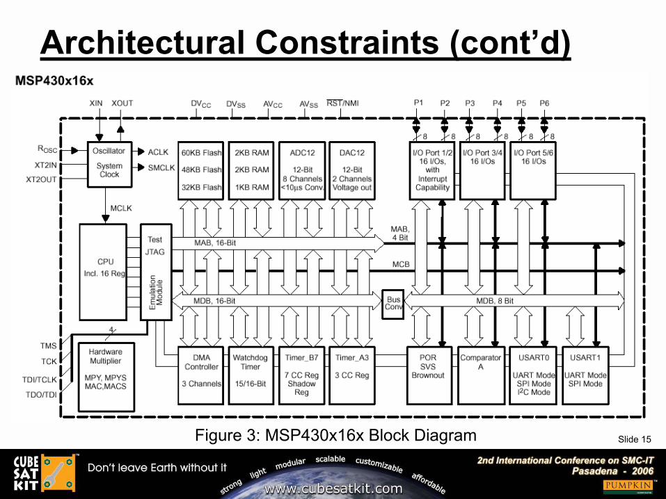
Architectural Constraints (cont�d)
Figure 3: MSP430x16x Block Diagram
Slide 16
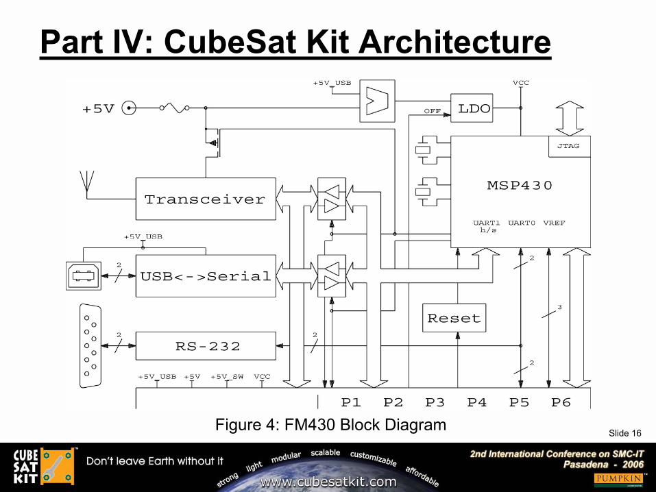
Part IV: CubeSat Kit Architecture
Figure 4: FM430 Block Diagram
Slide 17
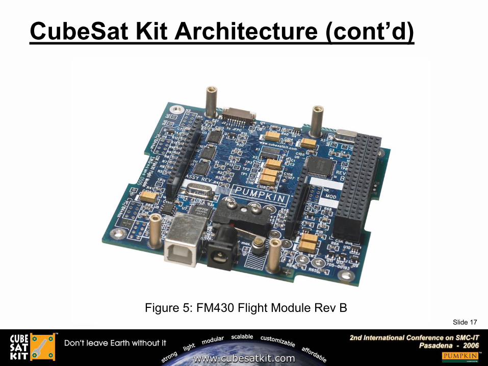
CubeSat Kit Architecture (cont�d)
Figure 5: FM430 Flight Module Rev B
Slide 18
Part V: CubeSat Kit Programming
� How does the choice of 16-bit MSP430 affect the programming environment of the CubeSat Kit? � 64KB memory space � MSP430F1612 has 5KB RAM and 55KB
Flash. RAM is especially limited, as is typical of microcontrollers. � C rules here. C++ is generally ill-suited to this small embedded
programming space. Assembly language is not required. HLL�s are not an option due to memory & speed limitations.
� Tools (compiler, linker, debugger, IDE, both commercial and free) are very good, standard C libraries are all present, multitasking RTOSes (e.g. Salvo) are available.
� As a CubeSat programmer, you�re never too far from the on-board hardware, at least at the early stages of development. Since much of the hardware in each CubeSat�s payload is unique and requires drivers & support, there are many opportunities for real-world learning when programming a CubeSat.

Slide 19
CubeSat Kit Programming (cont�d)
Figure 6: A CubeSat Kit Development Board with a UHF/VHF Radio Module

Slide 20
CubeSat Kit Programming (cont�d)
Figure 7: Screen Capture of Programming / Debugging IDE on CubeSat Kit

Slide 21
CubeSat Kit Programming (cont�d) � Detecting the presence of USB:
void TaskDetectUSB ( void ){
for (;;){
/* proceed if USB/MHX I/F is not in use */OS_WaitBinSem(BINSEM_USB_MHX_AVAIL_P, OSNO_TIMEOUT);OpenUSBMHXIF(USB);
if ( !FM430status.USBpresent && (P1IN & BIT7) ){
FM430status.USBpresent = 1;FM430Msg0("DetectUSB: USB connected.");
}else if ( FM430status.USBpresent && !(P1IN & BIT7) ){
FM430status.USBpresent = 0;FM430Msg0("DetectUSB: USB disconnected.");
}
CloseUSBMHXIF(USB); /* release USB/MHX I/F */OSSignalBinSem(BINSEM_USB_MHX_AVAIL_P);
OS_Delay(25); /* come back in 25 ticks */}
}
Listing 1: Sample Task to Detect Presence of USB Connection

Slide 22
CubeSat Kit Programming (cont�d) � Code modules developed for CubeSats include:
� Interfaces to various I2C devices to measure currents, voltages, etc. I2C is very popular because it�s a two-wire bus with a wide choice of supported devices.
� Interfaces to various SPI devices (e.g. magnetometers, MMC cards, other / slave processors).
� Interfaces to various asynchronous serial devices (e.g. transceivers and cameras).
� Watchdog / reset code (both internal and external). � On-board fault detection, collection and correction. � Multi-processor intercommunications. � Sun- and attitude-sensing algorithms. � Deployment & release mechanisms. � End-of-life / deorbit mechanisms. � In-flight reprogramming. � Active attitude control.

Slide 23
CubeSat Kit Programming (cont�d)
Figures 8 & 9: Final Exam for Stanford�s
AA236A class � semi-autonomous, remotely-controlled rovers based
on the CubeSat Kit

Slide 24
CubeSat Kit Programming (cont�d) � In CubeSat programming, the challenge is to do more with
less. More functionality, more reliability and more versatility with less mass, less power and fewer components.
� Example: The KatySat project has an on-board VHF/UHF AX.25 transceiver operating at 1200 bps. The VHF receiver presents ASCII data to the CubeSat Kit�s MSP430 Flight MCU at 4800bps.
Figure 10: KatySat ConOps
Slide 25
CubeSat Kit Programming (cont�d) � The challenge with the KatySat VHF/UHF module lies in the
fact that we would like to be able to listen on the VHF uplink 100% of the time. This requires a dedicated serial UART. But the FM430�s UART1 is dedicated to the 2.4GHz TT&C, and UART0 is shared among UART, I2C and SPI devices in the CubeSat. So the hardware UARTs are spoken for.
� The solution was to bit-bang the UART in software, using a TI example as the base code. During testing, it was found that a CPU clock of ~ 800kHz (the nominal DCO frequency) was insufficiently fast to guarantee reliable operation. Therefore the MSP430�s CPU clock was sourced from the HF crystal (7.3728MHz). Careful choices of timer modules, interrupt vectors and interface to the overlying RTOS ensure reliable operation within the larger multitasking framework of the SC software. ∆PD was deemed acceptable.

Slide 26
� What about more advanced functionality? � uIP�s embedded TCP/IP stack provides web and Telnet servers over
CubeSat Kit�s wireless or USB interfaces via SLIP. � HCC-embedded�s EFFS-THIN small-footprint PC compatible file
system provides easy interfacing between on-board SD card mass storage and development PCs.
� As long as memory requirements are not too extravagant, high-level functionality can be ported to the FM430 via a simple cut-and-paste or by linking to a library.
CubeSat Kit Programming (cont�d)
MSP430F149 CubeSat KitDemonstration Application
RAM Utilization
Application variables[66]
uIP TCP/IP stack, SLIPcode & web server [293]
FM430 USART0 buffers(256 Tx & 256 Rx) &control [539]FM430 USART1 buffers(256 Tx & 256 Rx) &control [539]Salvo RTOS (10 tasks &2 events) [107]
Stack [90]
Free [414]
MSP430F149 CubeSat KitDemonstration Application
Flash Utilization
main() & Salvo tasks[3880]
FM430 utility functions[1136]
uIP TCP/IP stack, SLIPcode & web server[5654]uIP web server files(*.html, etc.) [8700]
Salvo RTOS [1890]
ISRs & interrupt vectors[190]
C library functions(printf(), etc.) [1906]
Free [37828]
Figures 11 & 12: Flash and RAM utilization of a
uIP-enabled Salvo application on the
FM430

Slide 27
� All of the MSP430�s I/O is on the CSK bus connector. � The FM430�s ultralow power requirements mean that it
can run 24x7 during the entire mission. Additional processors (e.g. Linux SBC�s) can be added due to a variety of architectural features: � Multiple pins on CSK bus connector reserved for user. � MSP430�s NMI input enables simple handshake with other
processors. � SPI, I2C and UART all available for inter-processor
communications. � Up/downlink transceiver can be accessed directly via CSK bus
connector.
� Due to the SBC�s higher power consumption, its on-time duty cycle will necessarily be << 100%. The FM430 can manage it as an �on-demand coprocessor.�
Part VI: Architectural Extensions

Slide 28
This presentation is available online in Microsoft®
PowerPoint® and Adobe® Acrobat® formats at:
www.pumpkininc.com/content/doc/press/Pumpkin_SMC-IT-2006.ppt
and:
www.pumpkininc.com/content/doc/press/Pumpkin_ SMC-IT-2006.pdf
Notice

Slide 29
Q&A Session
Thank you for attending the
workshop!

Slide 30
Notes & References 1. CubeSat Design Specification, www.cubesat.org . 2. MSP430x16x block diagram from TI�s MSP430F1612 datasheets, www.ti.com. 3. CubeSat Kit User Manual, Pumpkin, Inc. 2005, www.pumpkininc.com. 4. Connex-xm platform spex, www.gumstix.com. 5. FOX Board Documentation page, Acme Systems, www.acmesystems.it. 6. AXIS ETRAX 100LX MCM 4+16 product brochure, Axis Communications AB, 2004,
www.axis.com. 7. The uIP Embedded TCP/IP Stack, Adam Dunkels, http://www.sics.se/~adam/uip/. 8. EFFS-THIN product specification, HCC-embedded, www.hcc-embedded.com.

Slide 31
Appendix � Speaker information
! Dr. Kalman is Pumpkin's president and chief technology architect. He entered the embedded programming world in the mid-1980's. After co-founding Euphonix, Inc � the pioneering Silicon Valley high-tech pro-audio company � he founded Pumpkin to explore the feasibility of applying high-level programming paradigms to severely memory-constrained embedded architectures. He holds two United States patents and is a consulting professor at Stanford University.
� Acknowledgements ! Stanford Professor Bob Twiggs' continued support for the CubeSat Kit, and his input on enhancements and
suggestions for future CubeSat Kit products, are greatly appreciated. ! Pumpkin�s Salvo and CubeSat Kit customers, whose real-world experience with our products helps us improve
and innovate.
� Salvo, CubeSat Kit and CubeSat information ! More information on the Pumpkin�s Salvo RTOS and Pumpkin�s CubeSat Kit can be found at
http://www.pumpkininc.com/ and http://www.cubesatkit.com/, respectively. ! More information on the open CubeSat standard and the CubeSat community can be found at
http://www.cubesat.info/.
� Copyright notice © 2006 Pumpkin, Inc. All rights reserved. Pumpkin and the Pumpkin logo, Salvo and the Salvo logo, The
RTOS that runs in tiny places, CubeSat Kit, CubeSat Kit Bus and the CubeSat Kit logo are all trademarks of Pumpkin, Inc. All other trademarks and logos are the property of their respective owners. No endorsements of or by third parties listed are implied. All specifications subject to change without notice.
First presented at the 2nd IEEE International Conference on Space Mission Challenges for Information Technology in
Pasadena, California on July 17, 2006.