PHYSICAL REVIEW ACCELERATORS AND BEAMS 22, 114401 (2019)
6
Tailoring of an electron-bunch current distribution via space-to-time mapping of a transversely shaped, photoemission-laser pulse A. Halavanau , 1,2,* Q. Gao, 3,4 M. Conde, 3 G. Ha, 3 P. Piot , 1,2 J. G. Power, 3 and E. Wisniewski 3 1 Northern Illinois Center for Accelerator & Detector Development and Department of Physics, Northern Illinois University, DeKalb, Illinois 60115, USA 2 Fermi National Accelerator Laboratory, Batavia, Illinois 60510, USA 3 Argonne Wakefield Accelerator, Argonne National Laboratory, Lemont, Illinois 60439, USA 4 Accelerator laboratory, Department of Engineering Physics, Tsinghua University, Beijing 100084, China (Received 3 July 2019; published 5 November 2019) Temporally shaped electron bunches at ultrafast time scales are foreseen to support an array of applications including the development of small-footprint accelerator-based coherent light sources or as probes for, e.g., ultrafast electron-diffraction. We demonstrate a method where a transversely segmented electron bunch produced via photoemission from a transversely patterned laser distribution is transformed into an electron bunch with modulated temporal distribution. In essence, the presented transformation enables the mapping of the transverse laser distribution on a photocathode surface to the temporal coordinate and provides a proof-of-principle experiment of the method proposed in Reference [W. S. Graves, F. X. Kärtner, D. E. Moncton, and P. Piot, Intense Superradiant X Rays from a Compact Source Using a Nanocathode Array and Emittance Exchange, Phys. Rev. Lett. 108, 263904 (2012)] as a path toward the realization of compact coherent x-ray sources, albeit at a larger timescale. The presented experiment is validated against numerical simulations and the versatility of the concept, e.g., to tune the current-distribution parameters, is showcased. Although our work focuses on the generation of electron bunches arranged as a temporal comb it is applicable to other temporal shapes. DOI: 10.1103/PhysRevAccelBeams.22.114401 I. INTRODUCTION Spatio-temporal control of bright electron beams has a wide array of applications including compact-footprint accelerator-based light sources [1], ultrafast electron probe setups [2], and the possible development of efficient high-energy accelerator based on beam-driven wakefield- acceleration techniques [3]. One recurrent class of distri- bution that could benefit most of these applications is the case of a bunch train where the beam is organized as “microbunches” in time with a characteristic duration below ∼1 ps. Owing to the fast time scale involved, this type of distribution is challenging to compactly achieve in conventional accelerator beamlines where the three degrees of freedom are decoupled. The last decade has witnessed the development of accelerator beamlines where the phase- space coordinates associated with different degrees of freedom can be exchanged [4–7]. The present work combines one type of such a beamline with a photoemission source to control the temporal distribution of the photoemitted electron beam using an optical transverse-shaping technique to adequately alter the emission-triggering laser distribution on the photocathode surface. The considered space-to-time mapping beamline is a transverse-to-longitudinal phase space exchanger (TLEX) [8]. The principle of the TLEX can be best understood by considering the phase space coordinate ðx; p x ; y; p y ; ζ;p z Þ where ðx; y; ζÞ is the electron position with respect to a reference point (henceforth taken to be the electron bunch barycenter) and ðp x ;p y ;p z Þ is the corresponding momen- tum. In our convention, the beam propagates along the z direction so that p z ≫ p x ;p y . In addition, we define the relative longitudinal coordinate ζ ≡ z − hzi where h:i stands for the statistical averaging over the bunch distri- bution. Here we note, under the above assumptions, that ζ ≃ ct for a relativistic beam where c is the velocity of light and t the time coordinate defined with respect to the bunch barycenter. Therefore the longitudinal coordinate ζ is often referred to as the temporal direction. A common TLEX setup consists of a transverse-deflecting cavity (TDC) operating on the TM 110 at zero crossing mode flanked by two identical “dogleg” beamline each composed of two dipole magnets with the same deflecting angle but with reversed polarities. Under a simple linear model of * Present address: SLAC National Accelerator Laboratory, Menlo Park, California 94025, USA. Published by the American Physical Society under the terms of the Creative Commons Attribution 4.0 International license. Further distribution of this work must maintain attribution to the author(s) and the published article’s title, journal citation, and DOI. PHYSICAL REVIEW ACCELERATORS AND BEAMS 22, 114401 (2019) 2469-9888=19=22(11)=114401(6) 114401-1 Published by the American Physical Society
Transcript of PHYSICAL REVIEW ACCELERATORS AND BEAMS 22, 114401 (2019)
Tailoring of an electron-bunch current distribution via space-to-timemapping of a transversely shaped, photoemission-laser pulse
A. Halavanau ,1,2,* Q. Gao,3,4 M. Conde,3 G. Ha,3 P. Piot ,1,2 J. G. Power,3 and E. Wisniewski31Northern Illinois Center for Accelerator & Detector Development and Department of Physics,
Northern Illinois University, DeKalb, Illinois 60115, USA2Fermi National Accelerator Laboratory, Batavia, Illinois 60510, USA
3Argonne Wakefield Accelerator, Argonne National Laboratory, Lemont, Illinois 60439, USA4Accelerator laboratory, Department of Engineering Physics, Tsinghua University, Beijing 100084, China
(Received 3 July 2019; published 5 November 2019)
Temporally shaped electron bunches at ultrafast time scales are foreseen to support an array ofapplications including the development of small-footprint accelerator-based coherent light sources or asprobes for, e.g., ultrafast electron-diffraction. We demonstrate a method where a transversely segmentedelectron bunch produced via photoemission from a transversely patterned laser distribution is transformedinto an electron bunch with modulated temporal distribution. In essence, the presented transformationenables the mapping of the transverse laser distribution on a photocathode surface to the temporalcoordinate and provides a proof-of-principle experiment of the method proposed in Reference[W. S. Graves, F. X. Kärtner, D. E. Moncton, and P. Piot, Intense Superradiant X Rays from a CompactSource Using a Nanocathode Array and Emittance Exchange, Phys. Rev. Lett. 108, 263904 (2012)] as apath toward the realization of compact coherent x-ray sources, albeit at a larger timescale. The presentedexperiment is validated against numerical simulations and the versatility of the concept, e.g., to tune thecurrent-distribution parameters, is showcased. Although our work focuses on the generation of electronbunches arranged as a temporal comb it is applicable to other temporal shapes.
DOI: 10.1103/PhysRevAccelBeams.22.114401
I. INTRODUCTION
Spatio-temporal control of bright electron beams has awide array of applications including compact-footprintaccelerator-based light sources [1], ultrafast electron probesetups [2], and the possible development of efficienthigh-energy accelerator based on beam-driven wakefield-acceleration techniques [3]. One recurrent class of distri-bution that could benefit most of these applications is thecase of a bunch train where the beam is organized as“microbunches” in time with a characteristic durationbelow ∼1 ps. Owing to the fast time scale involved, thistype of distribution is challenging to compactly achieve inconventional accelerator beamlines where the three degreesof freedom are decoupled. The last decade has witnessedthe development of accelerator beamlines where the phase-space coordinates associated with different degrees offreedom can be exchanged [4–7].
The present work combines one type of such a beamlinewith a photoemission source to control the temporaldistribution of the photoemitted electron beam using anoptical transverse-shaping technique to adequately alter theemission-triggering laser distribution on the photocathodesurface. The considered space-to-time mapping beamline isa transverse-to-longitudinal phase space exchanger (TLEX)[8]. The principle of the TLEX can be best understood byconsidering the phase space coordinate ðx; px; y; py; ζ; pzÞwhere ðx; y; ζÞ is the electron position with respect to areference point (henceforth taken to be the electron bunchbarycenter) and ðpx; py; pzÞ is the corresponding momen-tum. In our convention, the beam propagates along the zdirection so that pz ≫ px; py. In addition, we define therelative longitudinal coordinate ζ ≡ z − hzi where h:istands for the statistical averaging over the bunch distri-bution. Here we note, under the above assumptions, thatζ ≃ ct for a relativistic beam where c is the velocity of lightand t the time coordinate defined with respect to the bunchbarycenter. Therefore the longitudinal coordinate ζ is oftenreferred to as the temporal direction.A commonTLEX setup consists of a transverse-deflecting
cavity (TDC) operating on the TM110 at zero crossing modeflanked by two identical “dogleg” beamline each composedof two dipole magnets with the same deflecting angle butwith reversed polarities. Under a simple linear model of
*Present address: SLAC National Accelerator Laboratory,Menlo Park, California 94025, USA.
Published by the American Physical Society under the terms ofthe Creative Commons Attribution 4.0 International license.Further distribution of this work must maintain attribution tothe author(s) and the published article’s title, journal citation,and DOI.
PHYSICAL REVIEW ACCELERATORS AND BEAMS 22, 114401 (2019)
2469-9888=19=22(11)=114401(6) 114401-1 Published by the American Physical Society

the TLEX beamline and treating the horizontally deflectingTDC as a thin lens, the coordinate of an electron in thefour-dimensional phase space (using angle instead ofmomentum) downstream of the TLEX is u ¼ Ru0, whereu≡ ðx; x0 ≡ px=pz; ζ; δ≡ pz=hpzi − 1Þ, with : referring tothe transpose operator, u0 is the corresponding vectorupstream of the TLEX, and the 4 × 4 R transfer matrix[6] is given by
R ¼�
0 A
−A−1 0
�with A≡
− L
η η − ξLη
−1η − ξ
η
!: ð1Þ
The parameters η≡ ∂x∂δ0 jx¼0 and ξ≡ ∂ζ
∂δ0 jζ¼0 are respectivelythe horizontal and longitudinal dispersion functions gener-ated by one dogleg and L the resulting path length. Theblock-antidiagonal nature of the transfer matrix is achievedwhen the cavity deflecting strength κ ≡ 2π
λrf
eV⊥cpz
satisfies κ ¼−1=η where λrf ≃ 23 cm is the rf wavelength, e is theelectronic charge, andV⊥ the deflecting voltage. It should benoted that the TLEXphase-space exchange occurswithin theðx; x0; ζ; δÞ phase space so that the ðy; y0Þvertical phase spaceremains uncoupled and is therefore ignored in our treatment.Owing to the block-antidiagonal nature of the transfermatrixR, the initial horizontal phase-space ðx; x0Þ coordinates aremapped to the longitudinal phase space (ζ; δ) and vice versa.It was suggested [7] and experimentally shown that such afeature could be taken advantage of to tailor the longitudinal(current) distribution of an electron beam [9–11].In most of the previous work, the current distribution is
experimentally controlled by locating an interceptive maskupstream of the TLEX. In the present work, a simpletransverse laser-shaping technique controls the transversephase-space distribution upstream of the TLEX which isthen mapped to the longitudinal phase-space distributiondownstream of the TLEX. We especially demonstrate thetransfer of the projected transverse laser distribution alongone of the transverse directions at the photocathode surfaceto the current distribution of the electron bunch down-stream of the TLEX.We specifically explore the formation of a modulated
current profile obtained from a shaped laser distributionconsisting of an array of transversely separated beamletsgenerated via shaping of the laser using a microlens array(MLA) system; see Refs. [12,13]. It should, however, bestressed that the developed technique is general and couldin principle be adapted to tailor arbitrary current distribu-tions using more elaborate laser-shaping methods employ-ing, e.g., a digital micromirror device [14].
II. EXPERIMENTAL SETUP
The experiment was performed at the Argonne WakefieldAccelerator (AWA) facility [15] diagrammed in Fig. 1(a). Inbrief, the AWA accelerator consists of a radio-frequency (rf)
photoemission source consisting of a 1þ 1=2-cell 1.3-GHzstanding-wave (SW) resonant cavity (dubbed “rf gun”)operating on the TM010;π mode. The rf gun is surroundedby three solenoidal lenses (L1, L2, and L3) to control thebeam size. The electron bunches are formed by impinging a3.4-ps [root mean square (RMS)] long ultraviolet (UV,λ ¼ 248 nm) pulse on a Cesium Telluride (Cs2Te) photo-cathode. The electron bunches reach an energy of ∼8 MeVdownstream of the rf gun and are then injected in a linearaccelerator (linac) consisting of four 7-cell SW resonant rfcavities operating on the TM010;π mode at 1.3 GHz. The finalbeam energy was E ¼ 46.7� 1 MeV during our experi-ment. Downstream of the linac section, four quadrupolemagnets provide control over the transverse beam param-eters upstream of the TLEX beamline.The TLEX beamline consists of two L ≃ 2.7 m-long
doglegs each introducing a longitudinal and horizontaldispersion of ξ ¼ −0.30 m and η ¼ −0.89 m resulting in atransverse-to-longitudinal demagnification of jR31j≡j ∂ζ∂x0j¼jξηj≃0.28. The TLEX beamline is followed by a verticallydeflecting cavity (TDC2) which, combined with a down-stream cesium-doped Yttrium aluminum garnet (YAG)scintillating screen (YAG3) provides a direct measurementof the final current distribution [16]. The accelerator
(a)
(b)
(e) (f) (g)
(c) (d)
FIG. 1. Overview of the AWA facility (a). The rf-gun includesthree solenoids (L1-3). The “CAV” labels correspond to theaccelerating cavities, “Q” and “D” respectively refer to thequadrupole and dipole magnets, and “TDC” to the transversedeflecting cavities. The TLEX beamline comprises the elementsD1, D2, TDC1, D3, and D4. The density plots (b–d) and(e–g) respectively represent the simulated transverse and longi-tudinal phase spaces at the cathode surface (b,e), and YAG1 (c,f)and YAG2 (d,g) locations. The initial laser pattern is idealized asa 5 × 5 array of uniform beamlets.
A. HALAVANAU et al. PHYS. REV. ACCEL. BEAMS 22, 114401 (2019)
114401-2

beamline also includes YAG screens upstream (YAG1) anddownstream (YAG2) of the TLEX; see Fig. 1(a).
III. GENERATION OF TEMPORALLYMODULATED BEAM
The MLA system used to tailor of the laser distributionconsists of a pair of 10 × 10-mm2 square array consistingof spherical microlenses with effective focal lengths of5.1 mm and pitch of 300 μm along both directions. TheMLAs were installed on a rotatable mount to remotelycontrol the array orientation such to (i) pre-compensatefor the rotation arising from the Larmor precession as thebeam propagates through the rf-gun solenoidal lenses and(ii) to dynamically control the electron beam’s longitudinalmodulation downstream of the TLEX by varying therotation angle of the pattern upstream of the TLEX.A typical transverse pattern generated by the MLA
appears in the inlet of Fig. 1(a) with 6D phase-spacedisplayed in Fig. 1(b–g), and is used as input for thenumerical simulations of the process. All the supportingnumerical simulations presented in this paper are per-formed with the beam-dynamics program IMPACT-T [17]which represents the electron bunch as a collection of200 000 macroparticles (each representing ∼10 000 elec-trons) and tracks the corresponding distribution in an user-specified accelerator beamline described by tabulatedelectromagnetic field maps. The IMPACT-T software alsomodels space-charge effects using a particle-in-cell algo-rithm to solve Poisson’s equation in the beam’s rest framebefore computing the resulting electromagnetic fields inthe laboratory frame and applying the correspondingLorentz force on each macroparticle. Figures 1(b–d)and 1(e–g) respectively display snapshots of the simulatedhorizontal and longitudinal phase-space evolution along theAWA beamlines for an optimized set of beam parameters.The simulation demonstrates the process wherein themodulated transverse phase-space [Fig. 1(c)] is exchangedwith the smooth longitudinal phase space [Fig. 1(f)] to yielda temporally modulated current distribution [Fig. 1(g)].The MLA optical system was configured to produce a
laser distribution consisting of a transverse array ofbeamlets with a pitch of d ¼ 2.5� 0.2 mm. The initialUV laser distribution recorded on the “virtual” photo-cathode—a one-to-one optical image of the photocathodesurface—appears in Fig. 2(a). The laser intensity was tunedto maintain the total bunch charge to Q ¼ 250� 50 pC,yielding ∼10 pC=beamlet, throughout the experiment.The transverse electron-bunch distribution recorded atYAG1, upstream of the TLEX beamline, confirms thatwith proper solenoidal-lens settings the multibeam patterncan be imaged in the (x; y) plane [12]; see Fig. 2(b). Itshould be noted that the imaged pattern is generally rotatedas the beam reaches the location of YAG1 (zYAG1) by the
Larmor angle ϑL ¼ R zYAG10eBðzÞ
2cγðzÞβðzÞ dz acquired as the bunch
experiences the axial magnetic field produced by thesolenoidal lenses surrounding the rf gun (here γ theLorentz factor and β≡ ffiffiffiffiffiffiffiffiffiffiffiffiffiffiffiffiffi
1 − 1=γ2p
). For the solenoidal lenssettings used in the experiment ϑL ≃ 60°. Consequently,the pattern laser distribution is rotated by an angle −ϑL[compared to what displayed in Fig. 2(a) for clarity] in orderto obtained an nonrotated distribution at YAG1 [Fig. 2(b)].In order to properly match the multibeam array param-
eters so to provide a longitudinally modulated electronbeam downstream of the TLEX, four quadrupole magnets(Q1-4; see Fig. 1) were available upstream of the TLEX[18]. Nominally, an imaging was obtained when poweringonly Q1 and Q4 with respective magnetic-field gradientof B0
1 ≃ 0.7 T=m and B04 ≃ −0.7 T=m [where the gradient
is defined as B0 ≡ ∂Bx∂y ¼ ∂By
∂x with Bi (i ¼ x; y) being thetransverse magnetic field components]. Under these set-tings, the temporal bunch distribution downstream ofthe TLEX consists of five microbunches displayed inFig. 2(c) and in qualitative agreement with the simulatedfinal longitudinal-phase-space distribution; see Fig. 2(d)thereby confirming that the beamline realizes an imagingof one of projections associated with the laser transversedistribution on the longitudinal (temporal) coordinate.It should be noted that due to the beamline limited
aperture, nonoptimized transport, and possible beam mis-alignment the side beamlets are not fully transmittedresulting in a decrease of their charges and eventuallyone of the beamlets not being transmitted downstream ofthe TLEX beamline. This lack of transmission is not a
(a)
(c) (d)
(b)
FIG. 2. Initial (unrotated) ultraviolet laser distribution mea-sured on the virtual photocathode (a) and corresponding electron-beam distributions measured at YAG1 (b) and YAG3 with TDC2powered (c) with associated horizontal (YAG1) and longitudinal(YAG3) distributions (d). The shaded area in (a) indicates the rowof beamlets selected for the quadrupole-magnet scan experiment(see text for details).
TAILORING OF AN ELECTRON-BUNCH CURRENT … PHYS. REV. ACCEL. BEAMS 22, 114401 (2019)
114401-3
fundamental limitation and could be properly addressedin an optimized setup. Likewise, it is exacerbated, in thepresent configuration, by the large (2.5 mm) spacingbetween the beamlets, yielding the discrepancy in beamletcount in Fig. 3(b–f). Reaching sub-ps bunching will even-tually rely on shorter spatial period on the cathode surface.Nevertheless, the capabilities enabled by the proposed
technique offer a significant improvement over setupspreviously considered. Such a capability is of primeimportance compared to setups previously investigated,e.g., in Refs. [9,11], as it does not require any interceptivemask and is thereby compatible with, e.g., high-duty-cycleaccelerators contemplated as next generation accelerator-based light sources [19,20]. In addition, given that theshaping does not have any beam-intercepting hardware,the final distribution can, in principle, be dynamicallycontrolled by varying the accelerator magnets, or alteringthe laser distribution at fast time scales [OðkHzÞ].
IV. DYNAMICAL CONTROL OF THE BEAMTEMPORAL MODULATION
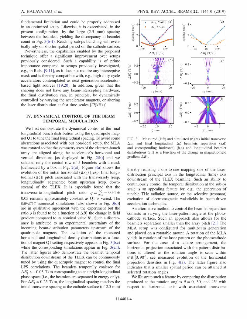
We first demonstrate the dynamical control of the finallongitudinal bunch distribution using the quadrupole mag-net Q1 to tune the final longitudinal spacing. To avoid someaberrations associated with our non-ideal setup, the MLAwas rotated so that the symmetry axes of the electron-buncharray are aligned along the accelerator’s horizontal andvertical directions [as displayed in Fig. 2(b)] and weselected only the central row of 5 beamlets with a mask[delineated by a box in Fig. 2(a)]. Figure 3(a) shows theevolution of the initial horizontal (Δx0) [resp. final longi-tudinal (Δζ)] pitch associated with the transversely [resp.longitudinally] segmented beam upstream [resp. down-stream] of the TLEX. It is especially found that thetransverse-to-longitudinal pitch ratio ϱ≡ Δζ
Δx0¼ 0.34�
0.03 remains approximately constant as Q1 is varied. TheIMPACT-T numerical simulations [also shown in Fig. 3(d)]are in qualitative agreement with the experiment but theratio ϱ is found to be a function of ΔB0
1 the change in fieldgradient compared to its nominal value B0
1. Such a discrep-ancy is attributed to an experimental uncertainty of theincoming beam-distribution parameters upstream of thequadrupole magnets. The evolution of the measuredhorizontal and longitudinal density distributions as a func-tion of magnet Q1 setting respectively appears in Fig. 3(b,c)while the corresponding simulations appear in Fig. 3(e,f).The latter figures also demonstrate the beamlet temporaldistribution downstream of the TLEX can be continuouslytuned by using the quadrupole magnet to control the finalLPS correlations. The beamlets temporally coalesce forΔB0
1 ≃ −0.05 T=m corresponding to an upright longitudinalphase space (i.e., the beamlets are separated in energy only).For ΔB0
1 ≃ 0.25 T=m, the longitudinal spacing matches theinitial transverse spacing at the cathode surface (of 2.5 mm)
thereby realizing a one-to-one mapping one of the laser-distribution principal axis in the longitudinal (time) axisdownstream of the TLEX beamline. Such an ability tocontinuously control the temporal distribution at the sub-psscale is an appealing feature for, e.g., the generation oftunable THz radiation source, or the selective (resonant)excitation of electromagnetic wakefields in beam-drivenacceleration techniques.An alternative method to control the beamlet separation
consists in varying the laser-pattern angle at the photo-cathode surface. Such an approach also allows for thebeamlets separation smaller than the array pitch [21] TheMLA setup was configured for multibeam generationand placed on a rotatable mount. A rotation of the MLAyields in rotation of the laser pattern on the photocathodesurface. For the case of a square arrangement, thehorizontal projection associated with the pattern distribu-tions is altered as the rotation angle is scan withinθ ∈ ½0; 90°�; see measured evolution of the horizontalprojection densities in Fig. 4(a). The latter figure alsoindicates that a smaller spatial period can be attained atselected rotation angles.We illustrate such a feature by comparing the distribution
produced at the rotation angles θ ¼ 0, 30, and 45° withrespect to horizontal axis with associated transverse
(a) (d)
(e)
(f)
(b)
(c)
FIG. 3. Measured (left) and simulated (right) initial transverseΔx0 and final longitudinal Δζ beamlets separation (a,d)and corresponding horizontal (b,e) and longitudinal beamletdistributions (c,f) as a function of the change in magnetic-fieldgradient ΔB0
1.
A. HALAVANAU et al. PHYS. REV. ACCEL. BEAMS 22, 114401 (2019)
114401-4

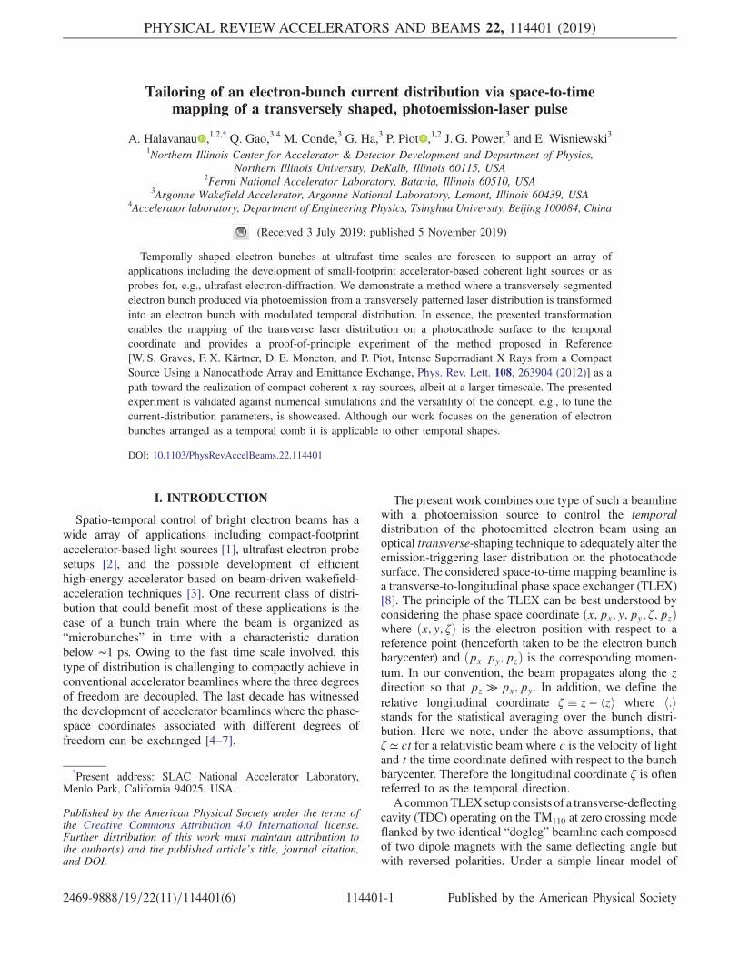
distributions presented in Fig. 4(b,e,h). The resultingcurrent distributions after transport through the TLEXbeamline appear in Fig. 4(c,f,i). For the nominal case ofan upright pattern, the bunch separation is Δζ ≃ 1.7 mmwhile features with spatial scale below 500 μm areobserved on the current profile for the case θ ¼ 30°.Likewise, Fig. 4(d,g,j) gives the bunch form factor
bðfÞ ≡����Z þ∞
∞ΛðζÞe−i2πfζ=cdζ
����; ð2Þ
where Λ is the normalized (Rþ∞∞ ΛðζÞdζ ¼ 1) charge dis-
tribution associated with each of the cases. The latterquantity confirms that nonzero angle provides higher-frequency spectral content. It should be noted that theobservable features are limited by the resolution of ourlongitudinal diagnostics (Δζ ∼ 200 μm) which thereforegive an upper limit f < 1.5 THz on the spectrum (thisupper frequency would ultimately be controlled by the
attainable single-beamlet duration). Additionally, the for-mation of smaller, e.g., suboptical-scale, structures is ulti-mately limited by optical aberrations in the TLEX beamline[22]. It should however be pointed out that the spectralcontent achieved in the presented simple proof-of-principleexperiment could be of interest, with minor improvements,to produce prebunched beams necessary for the generationof tunable coherent THz undulator radiation such as foreseenin pump-probe experiments planned at x-ray user facilities[23]. The method could also serve as an alternative to arecently proposed sub-mm density-modulation schemebased on the interaction of the electron bunch with a laser[24]. Finally, it should be pointed out that the two methodsexplored for controlling the final current distribution (quad-rupole magnet and rotation of the initial laser pattern) couldbe combined to provide a greater flexibility [21].
V. CONCLUSION
In summary, we demonstrated space-to-time imaging ofone of the projections associated with a photo-emissionlaser distribution impinging on a photocathode to thelongitudinal (temporal) distribution of an electron beam.One promising application of the technique is the possiblegeneration of narrowband electromagnetic radiationenhanced at the wavelength λn ∼ Δζ=n (where n is aninteger). Reaching ultrashort wavelength (high harmonicnumber n) will require the use of smaller laser pattern ornanoengineered cathodes capable of producing trans-versely segmented beams [1,25,26]. In addition, attainingthese finer-scale modulations will also require a thoroughcontrol of optical aberrations along the accelerator and inparticular within the TLEX beamline [22,27,28]. Thepresented technique was shown to be versatile and allowfor dynamical control of the final longitudinal bunchdistribution. Although our proof-of-principle experimentfocuses on the generation of an electron-bunch comb, anylongitudinal distribution can in principle be realized owingto recent advances in laser-shaping techniques.
ACKNOWLEDGMENTS
This work was supported by the U.S. Department ofEnergy under Contracts No. DE-SC0011831 and No. DE-SC0018656 with Northern Illinois University. The AWAfacility operation is funded through the U.S. Departmentof Energy Contract No. DE-AC02-06CH11357. The workof A. H. and partially P. P. is supported by the U.S.Department of Energy under Contract No. DE-AC02-07CH11359 with the Fermi Research Alliance, LLC.
[1] W. S. Graves, F. X. Kärtner, D. E. Moncton, and P. Piot,Intense Superradiant X Rays from a Compact SourceUsing a Nanocathode Array and Emittance Exchange,Phys. Rev. Lett. 108, 263904 (2012).
(a)
(b)
(e)
(h) (i) (j)
(f) (g)
(c) (d)
FIG. 4. False color image of the horizontal beam distribution asa function of the MLA rotation angle at YAG1 (a). Measuredpeak-normalized beam transverse distribution (b,e,h) at YAG1(false-color image) with superimposed horizontal projection(shaded-area traces), corresponding current distributions mea-sured at YAG3 (c,f,i) with associated bunch form factors (d,g,j).The upper, middle, and lower rows respectively correspond topattern-rotation angles on YAG 1 of θ ¼ 0, 30, and 45°.
TAILORING OF AN ELECTRON-BUNCH CURRENT … PHYS. REV. ACCEL. BEAMS 22, 114401 (2019)
114401-5

[2] A. Zewail, 4D ultrafast electron diffraction, crystallography,and microscopy, Annu. Rev. Phys. Chem. 57, 65 (2006).
[3] A. A. Zholents et al., A preliminary design of the collineardielectric wakefield accelerator, Nucl. Instrum MethodsPhys. Res., Sect. A 829, 190 (2016).
[4] R. Brinkmann, Y. Derbenev, and K. Flöttmann, A lowemittance, flat-beam electron source for linear colliders,Phys. Rev. Accel. Beams 4, 053501 (2001).
[5] P. Piot, Y.-E Sun, and K.-J. Kim, Photoinjector generationof a flat electron beam with transverse emittance ratio of100, Phys. Rev. Accel. Beams 9, 031001 (2006).
[6] P. Emma, Z. Huang, K.-J. Kim, and P. Piot, Transverse-to-longitudinal emittance exchange to improve performanceof high-gain free-electron lasers, Phys. Rev. Accel. Beams9, 100702 (2006).
[7] P. Piot, Y.-E Sun, J. G. Power, and M. Rihaoui, Generationof relativistic electron bunches with arbitrary currentdistribution via transverse-to-longitudinal phase space ex-change, Phys. Rev. Accel. Beams 14, 022801 (2011).
[8] M. Cornacchia and P. Emma, Transverse to longitudinalemittance exchange, Phys. Rev. Accel. Beams 5, 084001(2002).
[9] Y.-E Sun, P. Piot, A. Johnson, A. H. Lumpkin, T. J.Maxwell, J. Ruan, and R. Thurman-Keup, Tunable Sub-picosecond Electron-Bunch-Train Generation Using aTransverse-To-Longitudinal Phase-Space Exchange Tech-nique, Phys. Rev. Lett. 105, 234801 (2010).
[10] T. Maxwell, P. Piot, J. Ruan, A. Lumpkin, R. Thurman-Keup, A. Johnson, and Y.-E. Sun, Proceedings ofIPAC2012, New Orleans, Louisiana, USA, p. 2789(2012), http://accelconf.web.cern.ch/AccelConf/IPAC2012/papers/WEPPP030.PDF.
[11] G. Ha et al., Precision Control of the Electron LongitudinalBunch Shape Using an Emittance-Exchange Beam Line,Phys. Rev. Lett. 118, 104801 (2017).
[12] A. Halavanau, G. Qiang, G. Ha, E. Wisniewski, P. Piot,J. G. Power, and W. Gai, Spatial control of photoemittedelectron beams using a microlens-array transverse-shapingtechnique, Phys. Rev. Accel. Beams 20, 103404 (2017).
[13] P. Schreiber, S. Kudaev, P. Dannberg, and U. D. Zeitner,Homogeneous LED-illumination using microlens arrays,Proc. SPIE Int. Soc. Opt. Eng. 5942, 59420K (2005).
[14] S. Li, S. Alverson, D. Bohler, A. Egger, A. Fry, S. Gilevich,Z. Huang, A. Miahnahri, D. Ratner, J. Robinson, andF. Zhou, Ultraviolet laser transverse profile shaping forimproving x-ray free electron laser performance, Phys.Rev. Accel. Beams 20, 080704 (2017).
[15] J. G. Power, M. E. Conde, W. Gai, Z. Li, and D. Mihalcea,Proceedings of the 2010 International Particle AcceleratorConference (IPAC10), Kyoto, Japan, p. 4310 (2010),
https://accelconf.web.cern.ch/accelconf/IPAC10/papers/thpd016.pdf.
[16] Q. Gao, J. Shi, H. Chen, G. Ha, J. G. Power, M. Conde, andW. Gai, Single-shot wakefield measurement system, Phys.Rev. Accel. Beams 21, 062801 (2018).
[17] J. Qiang, S. Lidia, R. D. Ryne, and C. Limborg-Deprey,Three-dimensional quasistatic model for high brightnessbeam dynamics simulation, Phys. Rev. Accel. Beams 9,044204 (2006).
[18] G. Ha, M. Cho, W. Gai, K.-J. Kim, W. Namkung, andJ. Power, Perturbation-minimized triangular bunch forhigh-transformer ratio using a double dogleg emittanceexchange beam line, Phys. Rev. Accel. Beams 19, 121301(2016).
[19] J. Stohr, Linac Coherent Light Source II (LCLS-II) Con-ceptual Design Report, 2011.
[20] A. A. Zholents et al., Proceedings of the 9th InternationalParticle Accelerator Conference (IPAC2018), Vancouver,BC, Canada, pp. 1266–1268 (2018), http://jacow.org/ipac2018/papers/tupmf010.pdf.
[21] A. Halavanau and P. Piot, Proceedings of the 9thInternational Particle Accelerator Conference(IPAC2018), Vancouver, BC, Canada (2018), p. 3372,http://ipac2018.vrws.de/papers/thpak063.pdf.
[22] E. A. Nanni and W. S. Graves, Aberration corrected emit-tance exchange, Phys. Rev. Accel. Beams 18, 084401(2015).
[23] B. Green et al., High-field high-repetition-rate sources forthe coherent THz control of matter, Sci. Rep. 6, 22256(2016).
[24] Z. Zhang, L. Yan, Y. Du, W. Huang, C. Tang, and Z.Huang, Generation of high-power, tunable terahertz radi-ation from laser interaction with a relativistic electronbeam, Phys. Rev. Accel. Beams 20, 050701 (2017).
[25] R. K. Li, H. To, G. Andonian, J. Feng, A. Polyakov, C. M.Scoby, K. Thompson, W. Wan, H. A. Padmore, and P.Musumeci, Surface-Plasmon Resonance-Enhanced Multi-photon Emission of High-Brightness Electron Beams froma Nanostructured Copper Cathode, Phys. Rev. Lett. 110,074801 (2013).
[26] A. Lueangaramwong, D. Mihalcea, G. Andonian, and P.Piot, Numerical simulations of early-stage dynamics ofelectron bunches emitted from plasmonic photocathodes,Nucl. Instrum. Methods Phys. Res., Sect. A 865, 119(2017).
[27] D. Yu. Shchegolkov and E. I. Simakov, Design of anemittance exchanger for production of special shapes ofthe electron beam current, Phys. Rev. Accel. Beams 17,041301 (2014).
[28] A. A. Zholents and M. S. Zolotorev, ANL/APS ReportNo. LS-327, 2011.
A. HALAVANAU et al. PHYS. REV. ACCEL. BEAMS 22, 114401 (2019)
114401-6