PHYSICAL REVIEW ACCELERATORS AND BEAMS 22, 042901 (2019)
11
Novel beryllium-scintillator, neutron-fluence detector for magnetized liner inertial fusion experiments C. L. Ruiz, 1,* J. D. Styron, 2 D. L. Fehl, 1,† K. D. Hahn, 1 B. McWatters, 1 M. A. Mangan, 1 G. W. Cooper, 2 J. D. Vaughan, 2 G. A. Chandler, 1 B. M. Jones, 1 J. A. Torres, 1 S. A. Slutz, 1 D. J. Ampleford, 1 M. R. Gomez, 1 E. Harding, 1 A. J. Harvey-Thompson, 1 and P. F. Knapp 1 1 Sandia National Laboratories, Albuquerque, New Mexico 87131-0001, USA 2 University of New Mexico, Albuquerque, New Mexico 87185, USA (Received 6 December 2018; published 22 April 2019) Progress in the development of a neutron detector employing the 9 Beðn; αÞ 6 Heðβ − ; τ 1=2 ¼ 807 msÞ reaction is reported. This detector’ s intended use is to estimate 2.45-MeV, deuterium-deuterium (DD) neutron yields from magnetized liner fusion (MagLIF) targets and proposed future gas-puff experiments at Sandia National Laboratory’ s Z facility, Albuquerque, NM. This unique detector employs a simple stacked- component construction: 23 flat beryllium plates (99% pure, 0.318 cm thick) sandwiched between 22 plastic scintillator sheets (BC-404, 1-mm-thick). Each Be plate and scintillator sheet is a planar square (10 cm on a side) and the assembly is enclosed in a cubical, sealed, 1.5-mm-thick, Al-walled box. Scintillation light due to deposited energy from the 6 He betas is emitted and transmitted edgewise to ultraviolet-transmitting Lucite light guides optically coupled to two, independent, high-gain photo- multiplier tubes. Reported here are details of the characterization of the neutron detection sensitivity (beta decay counts per incident neutron) of each photomultiplier tube side. These measurements were conducted at the Sandia National Laboratories ion beam facility, which provided beams of pulsed 175-keV deuterons focused onto a 2.6-micron thick deuterated erbium target (ErD 2 ). Neutrons were produced via the Dðd; nÞ 3 He reaction. The neutron flux (incident neutrons=cm 2 =sec) on the Be detector was inferred by the measurement of the protons from the equally branched Dðd; pÞT reaction. Steady-state neutron pulses incident on the Be detector induced the 6 He beta decay activity necessary to determine the detector’ s neutron sensitivity referred to as the F-factor. The rational, methodology, and experimental details behind this approach and the results with uncertainties of the subsequently determined F-factor of the Be detector are detailed. Additional comments regarding improvements to the calibration methodology plus future studies and the use of this detector in Z experiments will be discussed briefly. DOI: 10.1103/PhysRevAccelBeams.22.042901 I. INTRODUCTION Ongoing physics experiments at the Z facility (Sandia National Laboratory, New Mexico) are presently evaluating the magnetized liner inertial fusion (MagLIF) concept for inertial confinement-fusion studies with D 2 -filled targets [1]. Essential to making this assessment is a reliable and precise measurement of the, deuterium-deuterium (DD) neutron yield Y DD which is a quantity that can be compared with model predictions and serve as a monitor of shot-to- shot fusion yield variations. In the past, nuclear activation has been a simple, passive technique to diagnose neutron yield in such experiments. Presently at Z, the adopted, standard diagnostic for meas- uring DD neutron yields is the activation of indium ( 115 In): specifically, the 115 Inðn; n 0 Þ 115m In reaction with a 0.38 MeV threshold and an isomeric daughter nucleus ( 115m In) that emits a 336.23 keV gamma ray with a 4.49 hr half-life. The initial activity after a Z shot is a measure of Y DD . Details for this diagnostic, its characterization using a similar methodology, and application to Z have been published elsewhere [2,3]. We have been challenged to find an independent and complementary approach to estimating neutron yields at Z. The goals were to diminish activation from scattered neutrons by moving away from the source into the far radiation field and to provide an in situ means of detecting and counting activated nuclear decays in a much shorter * [email protected] † Retired Sandia National Laboratories, Albuquerque, New Mexico, USA. Published by the American Physical Society under the terms of the Creative Commons Attribution 4.0 International license. Further distribution of this work must maintain attribution to the author(s) and the published article’s title, journal citation, and DOI. PHYSICAL REVIEW ACCELERATORS AND BEAMS 22, 042901 (2019) 2469-9888=19=22(4)=042901(11) 042901-1 Published by the American Physical Society
Transcript of PHYSICAL REVIEW ACCELERATORS AND BEAMS 22, 042901 (2019)

Novel beryllium-scintillator, neutron-fluence detector for magnetized linerinertial fusion experiments
C. L. Ruiz,1,* J. D. Styron,2 D. L. Fehl,1,† K. D. Hahn,1 B. McWatters,1 M. A. Mangan,1
G.W. Cooper,2 J. D. Vaughan,2 G. A. Chandler,1 B. M. Jones,1 J. A. Torres,1 S. A. Slutz,1
D. J. Ampleford,1 M. R. Gomez,1 E. Harding,1 A. J. Harvey-Thompson,1 and P. F. Knapp11Sandia National Laboratories, Albuquerque, New Mexico 87131-0001, USA
2University of New Mexico, Albuquerque, New Mexico 87185, USA
(Received 6 December 2018; published 22 April 2019)
Progress in the development of a neutron detector employing the 9Beðn; αÞ6Heðβ−; τ1=2 ¼ 807 msÞreaction is reported. This detector’s intended use is to estimate 2.45-MeV, deuterium-deuterium (DD)neutron yields from magnetized liner fusion (MagLIF) targets and proposed future gas-puff experiments atSandia National Laboratory’s Z facility, Albuquerque, NM. This unique detector employs a simple stacked-component construction: 23 flat beryllium plates (99% pure, 0.318 cm thick) sandwiched between22 plastic scintillator sheets (BC-404, 1-mm-thick). Each Be plate and scintillator sheet is a planar square(10 cm on a side) and the assembly is enclosed in a cubical, sealed, 1.5-mm-thick, Al-walled box.Scintillation light due to deposited energy from the 6He betas is emitted and transmitted edgewise toultraviolet-transmitting Lucite light guides optically coupled to two, independent, high-gain photo-multiplier tubes. Reported here are details of the characterization of the neutron detection sensitivity (betadecay counts per incident neutron) of each photomultiplier tube side. These measurements were conductedat the Sandia National Laboratories ion beam facility, which provided beams of pulsed 175-keV deuteronsfocused onto a 2.6-micron thick deuterated erbium target (ErD2). Neutrons were produced via theDðd; nÞ3He reaction. The neutron flux (incident neutrons=cm2=sec) on the Be detector was inferred by themeasurement of the protons from the equally branched Dðd; pÞT reaction. Steady-state neutron pulsesincident on the Be detector induced the 6He beta decay activity necessary to determine the detector’sneutron sensitivity referred to as the F-factor. The rational, methodology, and experimental details behindthis approach and the results with uncertainties of the subsequently determined F-factor of the Be detectorare detailed. Additional comments regarding improvements to the calibration methodology plus futurestudies and the use of this detector in Z experiments will be discussed briefly.
DOI: 10.1103/PhysRevAccelBeams.22.042901
I. INTRODUCTION
Ongoing physics experiments at the Z facility (SandiaNational Laboratory, NewMexico) are presently evaluatingthe magnetized liner inertial fusion (MagLIF) concept forinertial confinement-fusion studies with D2-filled targets[1]. Essential to making this assessment is a reliable andprecise measurement of the, deuterium-deuterium (DD)neutron yield YDD which is a quantity that can be compared
with model predictions and serve as a monitor of shot-to-shot fusion yield variations.In the past, nuclear activation has been a simple, passive
technique to diagnose neutron yield in such experiments.Presently at Z, the adopted, standard diagnostic for meas-uring DD neutron yields is the activation of indium (115In):specifically, the 115Inðn; n0Þ115mIn reaction with a 0.38 MeVthreshold and an isomeric daughter nucleus (115mIn) thatemits a 336.23 keV gamma ray with a 4.49 hr half-life. Theinitial activity after a Z shot is a measure of YDD. Detailsfor this diagnostic, its characterization using a similarmethodology, and application to Z have been publishedelsewhere [2,3].We have been challenged to find an independent and
complementary approach to estimating neutron yields at Z.The goals were to diminish activation from scatteredneutrons by moving away from the source into the farradiation field and to provide an in situ means of detectingand counting activated nuclear decays in a much shorter
*[email protected]†Retired Sandia National Laboratories, Albuquerque,
New Mexico, USA.
Published by the American Physical Society under the terms ofthe Creative Commons Attribution 4.0 International license.Further distribution of this work must maintain attribution tothe author(s) and the published article’s title, journal citation,and DOI.
PHYSICAL REVIEW ACCELERATORS AND BEAMS 22, 042901 (2019)
2469-9888=19=22(4)=042901(11) 042901-1 Published by the American Physical Society

and immediate timescale (minutes after the experiment) toreport DD yields.We report here the construction, characterization, and
sensitivity of a novel neutron-yield detector compatiblewith the Z environment and, specifically, to MagLIF, DDpulsed neutron experiments. Guided by previously pub-lished designs [4–6], the new diagnostic is based on the9Beðn; αÞ6He reaction which has a neutron energy thresh-old of 0.67 MeV and a total reaction cross section of82.5 mb at 2.45 MeV [7]. Principally, beta electrons(3.5-MeV-end point) from decaying 6He (τ1=2 ¼ 0.807 shalf-life, branching ratio 0.9999) [8] from activated Beare absorbed in an adjacent plastic scintillator with sub-sequent visible light pulses produced and viewed by aphotomultiplier tube (PMT) and counted.The organization of this article is as follows. Section II
describes the operating principles of the detector andprincipal design studies of optimum neutron sensitivitiesfrom Monte-Carlo simulations. Section III details the con-figuration of the presently characterized detector derivedfrom these studies. Section IV summarizes how the neutronsensitivity, or the F-factor (counts=per incident neutron=cm2- sec), of the Be detector was measured from a known,pulsed, DD neutron source. Included in this section are theexperimental setup, data collection, and the activationdecay analysis as a function of PMT bias and countingelectronics parameters. The overall results of these char-acterizations (with uncertainties) are given in Sec. V.Section VI briefly describes the application of this detectorto MagLIF DD experiments, improvements to the asso-ciated-particle techniques (APT), future DT neutron sensi-tivity studies, precalibration checks, and concludingremarks. To emphasize the technique and formulation thereis an attached Appendix with mathematical and physicaldescriptions of the F-factor determination and the asso-ciated particle technique used to infer neutron fluenceproduction.
II. BASIC OPERATING PRINCIPLES OF THEBE-SCINTILLATOR DETECTOR FOR
DD NEUTRONS AT Z
Figure 1 sketches a simple detector concept in onedimension for a single pair of Be scintillator layers, shownedgewise with normal vectors pointing vertically awayfrom the neutron source. In this illustration, the upper layeris beryllium with a thickness ΔZBe, and the bottom layer isa plastic scintillator, thickness ΔZSC. A complete neutrondetector consists of N such layered pairs with an overalllength of ZTOT ¼ NZ1. It is assumed that the top face of theBe-scintillator stack is some distance from the neutronsource.Figure 1 also indicates various particle interactions, due
to a mixed-field radiation source (arrows A–E) produced byMagLIF experiments, which occur in a Be-scintillator pair.
For example, prompt, hard, gamma rays A, B (hν≳0.5 MeV) interact via Compton and pair-production proc-esses in both detector layers depositing energy in thescintillator and producing prompt (∼ns) light output signalsdetected by the PMT. Similarly, DD neutrons (Fig. 1,arrow C) from the source arrive at the detector simulta-neously and directly interact with the scintillator by elasticn-p processes, leading again to prompt, proton-inducedlight output signals.But more to the point, Fig. 1 also shows the neutron
interaction of interest (Fig. 1, arrow D), 9Beðn; αÞ6He, andthe subsequent route by which the activation informationmoves toward detection: (a) a fraction of the emitted beta-decay electrons from 6He escape the Be layer, pass theBe-scintillator boundary, and individually deposit anenergy dose in the scintillator; and (b) a fraction of eachdose is converted in the scintillator to a visible light pulse,converted by the PMT to a 20 ns wide signal and single-event counted long after (millisecond timescales) theprompt radiation has passed.Optimizing the efficiency of the detector is an exercise in
optimizing the geometrical parameters for this geometry[9]. The expected MFP (mean-free path) for DD neutrons is3.4 and 4.7 cm in beryllium and scintillator respectively.Thus, from a simple, exponential, uncollided flux point ofview [10–14] one may expect the Be-scintillator detector tohave an overall linear dimension ∼10 cm (∼3 MFP) with
FIG. 1. Individual n0, γ, β-interactions in a Be-BC404 (SC)detector pair. Prompt and delayed energy processes are indicatedin the scintillator (although backscattered results are not shown).Thickness parameters, ΔZBe and ΔZSC, together with theircorresponding β-ranges (Λ) are sketched (but not to scale).
C. L. RUIZ et al. PHYS. REV. ACCEL. BEAMS 22, 042901 (2019)
042901-2

some tens of paired Be and scintillator layers, each a fewmm thick since the average range for a nominal 6He betadecay electron (1.2 MeV) is 0.28 and 0.49 cm for berylliumand scintillator respectively.Realistic estimates of the detector response for several
geometric permutations were investigated using theMonte Carlo code MCNP [15]. A fixed detector volumewas chosen (10 cm × 10 cm surface, ZTOT ¼ 10.4 cmheight) such that ZTOT was held fixed at 10.4 cm asΔZBe andΔZSC were varied in thickness—0.25, 0.50, 0.75,1.00, 2.00, and 3.00 mm (a total of 36 possible geometricpermutations). In each case, there was an extra scintillatorlayer on top to pick up backward emitted beta electronsfrom the Be layer of the first layered pair. A lumped figureof merit, or detector efficiency, ηðΔZBe;ΔZBeÞ was calcu-lated using the product of MCNP FM4 and F8 tallies asshown in Fig. 2. The product defines the fraction of incidentneutrons that ultimately produce beta energy losses in thescintillator greater than 10 keV (expected minimum wheresignals may be measurable).The FM4 tally, which is a measure of the 6He nuclei
produced in each Be layer, incorporates the energy depen-dent neutron flux, the energy dependent 9Beðn; αÞ6He crosssection, the Be atom density, and the volume of each layer.This was calculated by propagating neutrons through thedetector geometry using an isotropic, point source of2.45 MeV DD neutrons located 50 cm directly abovethe detector stack. The F8 tally is a measure of the betadecay pulse-height energy spectrum and is found by
summing the response of each scintillator region. Thiswas calculated using an isotropic beta electron source termwith a Fermi energy spectrum of end point 3.5 MeV [16]that was randomly and uniformly distributed within eachBe layer (proportional to the number of 6He nucleiproduced in each Be layer from the first calculation).The default electron cutoff energy of 1 keV was imple-mented. Enough sample MCNP trajectories were takenfor each parameter combination to estimate η with anuncertainty ∼1% (at 95% confidence). Figure 2 shows ηestimated by MCNP for a stacked Be detector of NBe-scintillator pairs. One sees a family of curves that risefrom low values to a broad peak, and then a decrease. Thegeneral shape of these curves is based on the trade-offbetween increasing the activation (left of the peak) andincreased electron stopping (right of the peak).While the results shown in Fig. 2 provided insight into
how the efficiency would change with geometric design,the design of the Be-scintillator stack used for Z experi-ments was determined experimentally. A prototype wasbuilt with 2-mm thick scintillator sheets and tested onseveral MagLIF experiments. So much light output fromcaptured prompt radiation was recorded such that the decaycounts were unusable for several 100’s of milliseconds, atime span which overlapped the desired early-time countsdue to 6He decay. The scintillator thickness was thenreduced to 1 mm, and this problem no longer obtruded.The overall result of these studies was that (a) the detectorand counting equipment survived; and (b) after promptradiation had passed the detector, the output countingsignal of the Be-scintillator was directly proportional tothe remaining activity (counts/unit time) of the 6He as afunction of time but with a steady background count rate.A result from a separate study [9], using the scintillator
thicknesses modeled, showed that scintillators <1 mmhave a high counting efficiency at low discriminator levels(<20 mV), however, the thin scintillator limits the amountof energy that the beta particles can deposit; limiting thesignal amplitude of the measured signal and the desireddynamic range. Therefore, a 1-mm thick scintillator wasdeemed the most feasible choice for a Be detector designfor use at the Z facility.
III. CONFIGURATION OF THE BE DETECTOR
Guided by MCNP modeling and preliminary testing onZ, the final design for the Be-scintillator neutron detectorchosen for characterization is shown in Fig. 3. Shown arethe radiation sensitive “active area” and ancillary, visible-light collecting components.The active region is a cube (10 cm on a side) consisting
of vertically stacked, alternating layers of 3.18 mm,99.9% atomic purity Be (22 total) and 1 mm thick,BC-404 plastic scintillator [17] layers (23 total) normalto a neutron source. Each scintillator layer is faced with100-μm-thick, aluminized Mylar films—the aluminum side
FIG. 2. Estimated counting efficiency for a fixed dimensionberyllium/scintillator layer detector as a function of berylliumand scintillator thicknesses from coupled neutron/beta transportcalculations in MCNP6.
NOVEL BERYLLIUM-SCINTILLATOR, … PHYS. REV. ACCEL. BEAMS 22, 042901 (2019)
042901-3
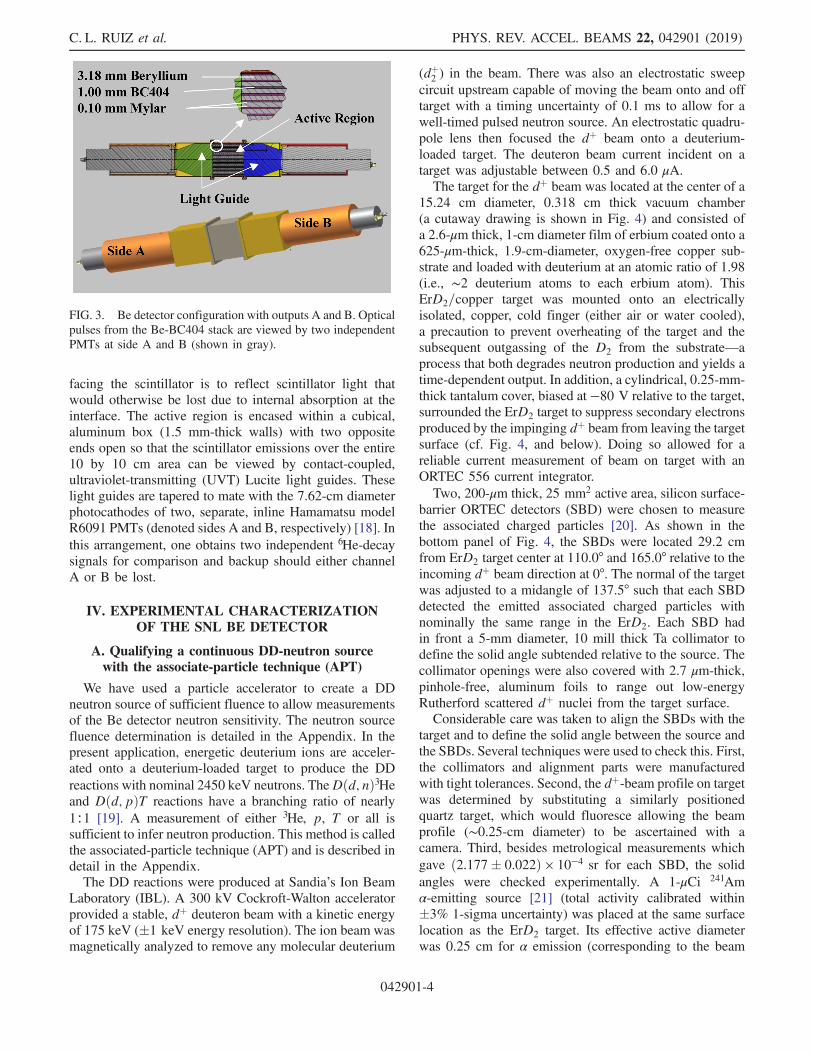
facing the scintillator is to reflect scintillator light thatwould otherwise be lost due to internal absorption at theinterface. The active region is encased within a cubical,aluminum box (1.5 mm-thick walls) with two oppositeends open so that the scintillator emissions over the entire10 by 10 cm area can be viewed by contact-coupled,ultraviolet-transmitting (UVT) Lucite light guides. Theselight guides are tapered to mate with the 7.62-cm diameterphotocathodes of two, separate, inline Hamamatsu modelR6091 PMTs (denoted sides A and B, respectively) [18]. Inthis arrangement, one obtains two independent 6He-decaysignals for comparison and backup should either channelA or B be lost.
IV. EXPERIMENTAL CHARACTERIZATIONOF THE SNL BE DETECTOR
A. Qualifying a continuous DD-neutron sourcewith the associate-particle technique (APT)
We have used a particle accelerator to create a DDneutron source of sufficient fluence to allow measurementsof the Be detector neutron sensitivity. The neutron sourcefluence determination is detailed in the Appendix. In thepresent application, energetic deuterium ions are acceler-ated onto a deuterium-loaded target to produce the DDreactions with nominal 2450 keV neutrons. TheDðd; nÞ3Heand Dðd; pÞT reactions have a branching ratio of nearly1∶1 [19]. A measurement of either 3He, p, T or all issufficient to infer neutron production. This method is calledthe associated-particle technique (APT) and is described indetail in the Appendix.The DD reactions were produced at Sandia’s Ion Beam
Laboratory (IBL). A 300 kV Cockroft-Walton acceleratorprovided a stable, dþ deuteron beam with a kinetic energyof 175 keV (�1 keV energy resolution). The ion beam wasmagnetically analyzed to remove any molecular deuterium
(dþ2 ) in the beam. There was also an electrostatic sweepcircuit upstream capable of moving the beam onto and offtarget with a timing uncertainty of 0.1 ms to allow for awell-timed pulsed neutron source. An electrostatic quadru-pole lens then focused the dþ beam onto a deuterium-loaded target. The deuteron beam current incident on atarget was adjustable between 0.5 and 6.0 μA.The target for the dþ beam was located at the center of a
15.24 cm diameter, 0.318 cm thick vacuum chamber(a cutaway drawing is shown in Fig. 4) and consisted ofa 2.6-μm thick, 1-cm diameter film of erbium coated onto a625-μm-thick, 1.9-cm-diameter, oxygen-free copper sub-strate and loaded with deuterium at an atomic ratio of 1.98(i.e., ∼2 deuterium atoms to each erbium atom). ThisErD2=copper target was mounted onto an electricallyisolated, copper, cold finger (either air or water cooled),a precaution to prevent overheating of the target and thesubsequent outgassing of the D2 from the substrate—aprocess that both degrades neutron production and yields atime-dependent output. In addition, a cylindrical, 0.25-mm-thick tantalum cover, biased at −80 V relative to the target,surrounded the ErD2 target to suppress secondary electronsproduced by the impinging dþ beam from leaving the targetsurface (cf. Fig. 4, and below). Doing so allowed for areliable current measurement of beam on target with anORTEC 556 current integrator.Two, 200-μm thick, 25 mm2 active area, silicon surface-
barrier ORTEC detectors (SBD) were chosen to measurethe associated charged particles [20]. As shown in thebottom panel of Fig. 4, the SBDs were located 29.2 cmfrom ErD2 target center at 110.0° and 165.0° relative to theincoming dþ beam direction at 0°. The normal of the targetwas adjusted to a midangle of 137.5° such that each SBDdetected the emitted associated charged particles withnominally the same range in the ErD2. Each SBD hadin front a 5-mm diameter, 10 mill thick Ta collimator todefine the solid angle subtended relative to the source. Thecollimator openings were also covered with 2.7 μm-thick,pinhole-free, aluminum foils to range out low-energyRutherford scattered dþ nuclei from the target surface.Considerable care was taken to align the SBDs with the
target and to define the solid angle between the source andthe SBDs. Several techniques were used to check this. First,the collimators and alignment parts were manufacturedwith tight tolerances. Second, the dþ-beam profile on targetwas determined by substituting a similarly positionedquartz target, which would fluoresce allowing the beamprofile (∼0.25-cm diameter) to be ascertained with acamera. Third, besides metrological measurements whichgave ð2.177� 0.022Þ × 10−4 sr for each SBD, the solidangles were checked experimentally. A 1-μCi 241Amα-emitting source [21] (total activity calibrated within�3% 1-sigma uncertainty) was placed at the same surfacelocation as the ErD2 target. Its effective active diameterwas 0.25 cm for α emission (corresponding to the beam
FIG. 3. Be detector configuration with outputs A and B. Opticalpulses from the Be-BC404 stack are viewed by two independentPMTs at side A and B (shown in gray).
C. L. RUIZ et al. PHYS. REV. ACCEL. BEAMS 22, 042901 (2019)
042901-4

diameter), which was detected by the SBDs and usedto determine each solid angle. The result was ð2.258�0.068Þ × 10−4 sr, which compares favorably with themetrological measurements. The α-source-determinedsolid angles were used in all subsequent data analysishere, with an estimated 1-sigma uncertainty of ∼� 3%.The associated-particle signals from the SBDs were
preamplified by ORTEC 142A modules, then amplifiedby ORTEC 672 amplifiers whose unipolar outputs were
routed to separate ORTEC multichannel analyzers. Thisnucleonic scheme allowed monitoring of the entiretritium and proton charged-particle energy spectra, andthe highest-energy portion of the lower energetic 3He ions.For example, Fig. 5 displays a particle energy spectrummeasured at SBD locations 110° and 165°, respectively.Having two SBDs at the 110° and 165° positions (see theAppendix) provided two measurements to infer neutronfluence. In each plot, the highest energy peak (in channelnumbers) corresponds to protons (2600–3000 channels),the middle peak by tritons (500–900 channels), and thelowest partial peak to 3He nuclei (<500 channels). Protonswere ultimately chosen as the associated particle todetermine the inferred neutron production. For redundantparticle monitoring, the bipolar outputs from the amplifierswere routed to single-channel analyzers (SCAs) for settingupper and lower level discrimination of only the protonpeak. The logic TTL outputs from these SCAs were routedto multichannel scalars (ORTEC Easy-MCS).Besides using two SBDs to monitor proton counts, a
third measurement monitored the current stability andconstancy of the incoming dþ beam. It was important tokeep the dþ beam on target and close to a steady-statecurrent to avoid time-dependent neutron-activation-ratecorrections (cf. the Appendix).Lastly, in Fig. 6 we show a correlation plot of the neutron
flux inferred by associated-particle proton measurementsat 165 and 110 degrees. The data indicate consistently theagreement of inferred yield from the 165- and 110-degreecharge-particle detectors. Taking all these measurementstogether, one argues that the target-assembled IBL accel-erator experiments provide an appropriate and stable sourceof DD neutrons for characterizing the Be-based scintillatorneutron detector.
counts
FIG. 5. Associated-particle energy spectra from the 165 and110 degrees SBDs for the equally branched DD reactions:Dðd; nÞ3He and Dðd; pÞT. Blue spectra pertain to the 165-degdetector. Red spectra pertain to the 110-deg detector.
FIG. 4. (a) Experimental APT vacuum chamber. (b) Associated-particle plus Be detector experimental layout. The angle θ is either110 or 165 degrees. The 5-mm diameter, Ta collimators define theSBDs subtending solid angles.
NOVEL BERYLLIUM-SCINTILLATOR, … PHYS. REV. ACCEL. BEAMS 22, 042901 (2019)
042901-5

B. Be detector measurement proceduresand experimental setup
At 175 keV incident-energy, kinematic calculations sug-gest that the Be detector’s center-normal (10-cm by 10-cm)face be placed at 95.0 degrees relative to the beam direction tosubtend 2450 keV DD neutrons. The PMTs, chosen for theirhigh gain (5 × 10⁶), linearity, and low dark-noise character-istics were placed on opposite sides of the Be detectorcomponent to detect scintillator signals. These tubes have7.6-cm diameter photocathodes and linear-focusing dynodegrids; they were connected to appropriate Hamamatsu resis-tive divider-chain bases. The high-voltage bias for each PMTwas supplied by Stanford 336’s power supplies [22]. Signalsfrom each PMT were fed directly through 50-Ω, RG-223Co-Ax cable into output-signal-adjustable ORTEC 584constant-fraction discriminators (CFDs). The negative out-puts of the discriminatorswere then directed toORTECEasy-MCS modules for single-event-rate counting.Neutron production from the target was monitored by
gating a four-second deuteron beam-on-target pulse with≤0.1-ms gating uncertainty. This uncertainty was due to thedelay of switching on the current from a power supplyconnected to electrostatic deflection plates steering thebeam onto the downstream ErD2 target. Furthermore,during beam-on-target time, the variation in beam currentwas less than 0.5%, and, thus, time-dependent, activationcorrections were unnecessary. During the irradiation time,t0, both buildup and decay of 6He is taking place and theactivity is not counted. In addition, if copious counts due toneutrons and prompt-gamma rays interacting in the scin-tillator are observed during t0 would invalidate any mea-surements during this time interval. A similar result couldalso occur due to the 0.1-ms beam-off-target uncertaintyoverlapping the beginning of the 6He decay activity. This
effect was not observed here. Therefore, only the decay ofthe 6He induced activity after t0 was absolutely counted fora fixed time counting interval between times t1 and t2.Because of the 0.807 s half-life decay of 6He and potentialequilibrium (activation buildup and decay activity becomeequal), it was not advantageous to induce activation for toomany half-lives by increasing the t0 neutron irradiation.Therefore, a practical four-second or less irradiation time(t0 ¼ 5 half-life) was chosen. As mentioned, particlespectra were collected only during beam-on time. At theend of four seconds the beam-on gate was turned off tostop the beam impinging on the target and a separate gateturned on (within 0.1-ms) to trigger the Easy-MCS’s for a12-second 6He decay counting interval. The Easy-MCS’swere set to a 0.1-second dwell time (time bin). Thecounting was stopped by a gate at the end of 12 secondsallowing for a four-second period where no counts wererecorded, although this was arbitrarily decided.The entire time gating scheme , as depicted in Fig. 7,
for each four-second beam-on interval was repeated every20 seconds for a preselected number of beam-on-plus-decay counting periods. This gating scheme was controlledto submillisecond timing by a programmable Stanford 648delay-gate generator. For the four-second interval that thecurrent was on target the neutron production was minimaland resulted in low count rates during the 12-secondcounting interval. It was found that with a 2-μA, beamcurrent, 120 beam pulses were necessary to obtain sta-tistically significant decay data, which required 40 minutesof operating time. Several longer distances between thedetector and the neutron source were also studied. Theselonger distances required 360 or more pulses to obtain goodstatistics. Data from the Be detector labeled No. 2 wascollected with the following geometric parameters: thefront center face of the detector was located either 178 or
Y =
Neu
tron
Flu
x (n
cm
-2 s
-1)
@ 1
65° t
o A
xis
FIG. 6. Correlation plot between neutrons inferred between theAP measurements at 110 and 165 degrees for 24 experimentalDD runs.
FIG. 7. Irradiating counting and gating scheme in one ith cycle.The neutron irradiation time period of 4 s is in the pink region.The counting of Be decay is for 12 s and in green. The gray areaindicates no-counting for 4 s. A complete ith cycle repeated every20 seconds for a minimum of 120 cycles.
C. L. RUIZ et al. PHYS. REV. ACCEL. BEAMS 22, 042901 (2019)
042901-6

356 mm (�2 mm) from the ErD2 target at 95° relative tothe 0° dþ beam.Multichannel scaling measurements (MCS) of the 6He
decay data were obtained for each detector as a function ofPMT bias (−1800 to −2400 V) and 584 CFD discriminatorsettings (25 to 200 mV). These settings were dictated by theneed for good statistics and useful signal-to-backgroundratios (SNR) in the decay data. Itmust be pointed out that lowdiscriminator settings and high biases were the most unfav-orable settings with a SNR < 1. Conversely, high discrimi-nator settings and low biases tended to eliminate the betainduced scintillator detector signals, effectively detectingonly contributions from gamma-background signals.
C. Data analysis
As a function of PMT bias, MCS discriminator thresh-olds, and source distances, 25 decay data sets for each ofthe two PMTs (detector sides A and B) were analyzed. Theanalysis of the data collected with this detector (labeledNo. 2, side A) for experimental data run 64 is typical ofother runs obtained with this detector and is consideredhere as an example. In this case the PMT bias anddiscriminator threshold was −2200 V and VLO¼25mV,respectively. Figure 8 displays the Ai (counts/dwell time) vsith dwell-time bin. For analysis, the time assignment wastaken at the midpoint of each bin fti ¼ 0.05þ 0.1ði − 1Þgin seconds for all i ¼ 1;…; 120 bins per 12 s irradiationcycle. The first-time bin (t1 ¼ 0.05 s) in each cyclecoincides with the start of counting after the end of theneutron irradiation time t0 (cf. Fig. 7). Visual inspectionand a priori physics suggest that the fit function for Fig. 8,AfitðtiÞ, should include an exponential beta decay and anadditive (but time-rate) constant background. Hence,
we choose the following function to fit actual counts inFig. 8 as
AfitðtiÞ ¼ A0 exp½−ðln2=τ1=2Þti� þ B; ð1Þ
where the parameters, A0, τ1=2, and B are the summedinitial activity from all irradiation cycles, the 6He decayhalf-life, and the background count rate (from extraneoussources assumed constant in time). The solid curve (leftscale) in Fig. 8 is a fit of AfitðtiÞ to these data, which declinefrom∼3800 counts=bin (cpb) at 0.05 s to∼2500 cpb at latetime (background) and from which one infers an initial betacount rate of ∼1300 cpb. A SNR estimate for these initialcounts is ∼
ffiffiffiffiffiffiffiffiffiffi1300
p≈ 36 (alternatively, NSR ≈ 3%) and is
adequate for a further statistical analysis. Figure 8 alsoillustrates why 120 cycles of neutron beam pulses werenecessary for a reasonable estimate of the initial betadecays: on the right-hand scale one sees fAfitðtiÞ=120g,which peaks at ∼32 cpb, declines to 21 cpb (background),and roughly yields 11 cpb attributable to initial beta decays,giving a NSR of ∼30% or SNR ∼ 3. This level of noiselimits the precision of the initial beta estimate.Of these desired fit parameters, the initial activity A0 is
most important because it relates directly to the neutronsensitivity of the Be detector. The other two parameters areuseful in identifying outlying data: for example, if τ1=2differs significantly from the published value of the half-life, one may suspect a problem with the production of aclean 6He beta decay component and detection or the late-time background activity B may not be constant in time. Itis not clear from these data where the constant backgroundspecifically originates. This component is most likely fromlong-lived neutron-gamma activation from the hardwareand concrete shielding some distance from the Be detector.A nonlinear, weighted least-squares minimization pro-
cedure was chosen to fit the data in Fig. 8 and estimatethe three parameters given in Eq. (1). The default Gauss-Newton (GN) technique from the MINITAB© suite of codeswas used, but the Levenson-Marquart (LM) also gavevirtually identical results. [23,24]. In run 64, side A, thefit values of A0 and B were 1367� 75 and 2502�13 counts=0.1-s bin. The uncertainties quoted for A0, Bare at the �2 sigma level (95% confidence intervals) andare obtained from the regression algorithm. Figure 9examines the consistency of these measurements overthe series of runs for both A and B outputs of the Bedetector under test under various settings of the testparameters. Independently plotted in normal probabilityformat are the fitted, decay time estimates τ1=2 [Eq. (1)]from this series, altogether 28 runs of which three for side A(as noted) were regarded as outliers: there were beamon/off issues and distorted decay traces for these data andwere thus rejected in the analysis. Figure 9 shows τ1=2(A, B outputs) from the remaining runs which yield remark-ably similar, near-Gaussian distributions for τ1=2 to each
acti
vity
(cou
nts/
.1 s
)
FIG. 8. The decay curve for the Be neutron detector in run 64(side A), with a three-parameter, nonlinear, weighted least-squares fit. The extrapolated initial point A0 þ B at t0 is estimatedhere to be 3869 counts in 100 ms.
NOVEL BERYLLIUM-SCINTILLATOR, … PHYS. REV. ACCEL. BEAMS 22, 042901 (2019)
042901-7

other, despite varying test parameters. Combined τ1=2 datafrom both sides A and B yield a half-life mean of τ1=2 ¼0.8054 s with a sample standard deviation of 0.027 s.Both estimates bracket the published value of 0.807 shalf-life [8]. We conclude from this analysis, therefore, thatthe fundamental n → Be → 6He → β decay processes in theBe detector are working as expected.
V. SUMMARY OF F-FACTOR SENSITIVITYMEASUREMENTS
The 6He activation decay data for each experimentalset of parameters were collected and fitted as above todetermine the initial activity A0 with subsequent calculationof the F-factors. The experiments were performed with 120or 360 neutron pulses as dictated by needed statistics. Dueto limited accelerator availability PMT biases, discrimina-tor settings, and distances from source to detector face wereselected. This selection gave F factors with a dynamicrange of 18. Most measurements on detector No. 2 weredone with a PMT bias at −2000 V and discriminatorsettings between 25 to 200 mV in 25 mV steps. A fewadditional F factors were determined at −1800 and−2200 V. The −2200 V settings were also used to deter-mine F-factors by placing the front face of the detector35.6 cm from the source to check for 1=R2
eff (see theAppendix) solid-angle corrections. A good measure of thissource to detector distance correction is indicated byagreement with F-factors measured at two distances andfor each detector’s side A and side B with settings shown inFig. 10 these figures. Each F-factor is the average plus
standard error of the mean. The uncertainties ascribed toeach F-factor fall in the following categories: (a) countingstatistics of the AP measurements, �3%, (b) backgroundsubtraction, �1%, (c) time-varying beam currents, �0.1%,(d) deuteron beam energy uncertainties, �0.1%, (e) solidangle corrections for AP detectors, �3%, (f) solid anglecorrections of Be detector, �2%, (g) corrections due to fitsof the decay data,�3%, and (h) neutron flux inference fromthe APT calculation, �5%.
FIG. 9. Two normal probability plots of decay time estimates,for sides A and B, over 25 experimental runs. The meanand uncertainty is consistent with the accepted decay time of0.807 s.
FIG. 10. F-factors for Be detector No. 2 side A. The insetshows the correlation plot for F values determined at 17.8 and35.6 cm distances. The solid curves are drawn to aid the eye.STD is the source to detector distance.
C. L. RUIZ et al. PHYS. REV. ACCEL. BEAMS 22, 042901 (2019)
042901-8

This last uncertainty estimate is obtained by the follow-ing argument. The front center face of the detector, at95 degrees and at 17.8 and 35.6 cm distances respectively,subtended �12 and �8 degrees at the right-front and left-front detector edges. The DD neutron energy due to theseedges for the nearest distance was from 2510 to 2394 keV.The 9Beðn; αÞ6He cross sections at these extremes were≤5% above and below the nominal value of 82.5 mb at2450 keV neutron energy and drove the uncertainty quotedabove. Further justification can be observed from theF-factor agreement at 35.6 cm distance compared to17.8 cm which subtend different energy spreads. For ourBe detector with the front face at 17.8 and 35.6 cm distanceto an isotropic DD source, 218 and 60.5 msr respectivelywas determined with MCNP modeling. In MCNP theeffective solid angle is calculated by taking the productof the beryllium surface area and an average F4 tally;calculated using an isotropic source distribution and avoided geometry. Simple analytical calculations were doneto determine the solid angles obtained for each Be andscintillator layer as a function of source to layer distance.These results were summed, averaged and compare favor-ably with the MCNP results.In quadrature the uncertainty in F-factors on average is
�7.7% as indicated in the figures. These uncertainties arenot unrealistic considering the good agreement betweenthe F-factors determined at −2000 V from 25–200 mVdiscriminator settings and repeated at two distances forboth detector No. 2 sides A and B.
VI. FUTURE STUDIES ANDCONCLUDING REMARKS
The performance of the Be detector reported here is idealin dealing with the time-dependent, mixed radiation fieldproduced in Z MagLIF experiments. To date Be measure-ments have not been independent but are due to crosscalibrations with indium results. The transferring of theF-factor (neutron sensitivity) to measure MagLIF DDyields needs further work to determine independent yieldmeasurements. We have identified DD neutron scatteringfrom high Z components near the source that change theneutron spectrum incident on the Be detector implyingsensitivity corrections be made. In addition, depending onthe location of a detector, neutron activation of nearbysupport structures or shielding yield prompt gamma-raysignals superimposing the initial 6He decay and compro-mising the early part of the 0.807 s half-life decay. We areaddressing corrections to proper yield measurements byunderstanding scattering effects with MCNP modeling.Proper shielding of the Be detector is being explored toremove prompt gamma-ray interference. Since these cor-rections are very detailed, discussion on the application ofour methodology to determine MagLIF DD neutron yieldsand comparisons of neutron yields from indium activationwill be presented in a future publication.
We have made improvements to the associated-particletechnique to include the energy spectrum measurementof the 3He contribution from theDðd; nÞ3He reaction. Thiswas done by reducing the 3He energy loss by reducing thealuminum foil thickness in front of the SBDs from 2.6 to0.8 μm. With the reduction in stopping power from thisthinner aluminum filter we now detect the full peak ofthe 3He particle. This quantity is a direct measurement ina 1∶1 ratio of the neutrons produced per 3He particlemeasured and offers another approach to the determi-nation of neutron yield as opposed to that due to only theproton measurement. The 3He determination will alsoallow us to measure coincidence neutrons into a neutron-time-of-flight detector for the determination of both DDneutron sensitivity (coulombs/incident neutron) and aneutron impulse response function. This work is currentlyin progress.We are exploring using a gamma-ray source, such as
Co-60, to precheck the Be detectors for any changes indetection sensitivity. This source will be fixtured at adefined and repeatable location on the surface of the activearea of the detectors. The same counting electronicsassociated with a detector will be used for counting signalsfrom the detector with a chosen bias and discriminatorsetting, preferably at the highest neutron sensitivity(F-factor). Steady-state counts/unit time will be recordedin an MCS and checked for repeatability every few months.Changes in the counting due to aging of the scintillators,gain changes in the PMTs or discriminator levels in theCFDs will necessarily require calibrations at IBL.A preliminary study with DT neutrons suggests that the
Be detector as designed can be used to measure DT neutronyields, an important future consideration at Z. Thesestudies will also be presented in a future publication.
ACKNOWLEDGMENTS
Thanks to Ken Moy (Santa Barbara, California), IreneGarza, Robert Buckles, and Brent Davis (Las Vegas,Nevada) at Nevada National Security Sites (NNSS) formanufacturing the detector components and characterizingthe fidelity of two Be detector PMTs. Sandia NationalLaboratories is a multi-mission laboratory managed andoperated by National Technology and EngineeringSolutions of Sandia, LLC., a wholly owned subsidiaryof Honeywell International, Inc., for the U.S. Departmentof Energy’s National Nuclear Security Administrationunder Contract No. DE-NA-0003525. The views expressedin the article do not necessarily represent the views ofthe U.S. Department of Energy or the United StatesGovernment.
APPENDIX
A general expression [25–27] for the activation of anelemental sample of mass M and atomic weight Aw from a
NOVEL BERYLLIUM-SCINTILLATOR, … PHYS. REV. ACCEL. BEAMS 22, 042901 (2019)
042901-9

steady state neutron flux φ (n=cm2-sec) with a kineticenergy E (MeV) is given by Eq. (A1) as
ðC-BÞ ¼ ϕεaεbεcεdMNAσðEÞ× ½ð1 − e−λt0Þðe−λt1 − e−λt2Þ�=ðλAWÞ; ðA1Þ
where the quantities are as follows: εa is the naturalabundance, in our case, of 9Be; εb is the neutron detectionefficiency of the detector; εc is the self-attenuation ofneutrons from the detector casing; εd is the branching ratioof 6He beta decay;M is the amount of Be mass (gms);NA isAvogadro’s number; σðEÞ is the energy dependent neutronreaction cross section for 9Beðn; 4HeÞ6He; Aw is the atomicweight of activating material; λ is the decay constantln 2=τ1=2 of the sample isotope where τ1=2 is the half-life;t0 is the neutron irradiation time (not an instantaneous timepulse); t1 is the starting time for counting the decay activity(counts/unit time) after the end of t0; and t2 is the endingtime for counting the decay activity after t0. The 6He betadecay activation total counts between time interval of t1 andt2 is given by C (counts) corrected for background B.Background counts B occur over the same time interval t1to t2. Equation (A1) can be rearranged into the followingtwo expressions—(A2) and (A3)—as follows:
F ¼ ðC − BÞλ=½ϕð1 − e−λt0Þðe−λt1 − e−λt2Þ�; ðA2Þ
which also equals
F¼εaεbεcεdMNAσðEÞ=AW: ðA3Þ
Note that both expressions are composed of quantitiesthat are previously known or measurable from experiment.The quantity of choice here is defined by expression (A2)since these are quantities easily measured. Expression (A2)defines a detector’s neutron detection sensitivity (counts=per incident neutron=cm2)-sec. We call this expression theF-factor. The most important part of the expression is theinference on the production of neutron flux ϕ (n=cm2-sec)incident on the detector. This is defined as
ϕ ¼ N=ðAefft0Þ; ðA4Þ
where Aeff ðcm2Þ and Reff (cm) are the effective areasubtended and effective distance from a volumetric detectorto a source. Both quantities are obtained from MCNPmodeling to determine the effective subtending solidangle Ωeff . The effective area Aeff is given by
Aeff ¼ ΩeffðReffÞ2: ðA5Þ
The total neutrons N incident on the detector is deter-mined by the associated-particle technique [25–27]. Thistechnique here is applied to the DD fusion reaction to
determine from known parameters a produced or inferredneutron fluence. The technique employs calculational andexperimental procedures and makes important use ofpreviously studied Dðd; nÞ3He and Dðd; pÞT reactions asfunctions of deuteron kinetic energy. The calculational partis approached as follows. Imagine the production ofneutrons from theDðd; nÞ3He reaction at a certain deuteronenergy and emitted at a lab angle relative to the impingingdeuteron on a stationary deuterated target. The calculationof the number of neutrons, protons, tritium ions, or 3Heproduced, into a laboratory detector solid angle dependson the kinetic energy of the deuterons, differential crosssection, loading ratio of deuterium in the target, and thestopping power of the deuterated target compound. Thegeneral expression describing this process is
dY=dΩ ¼ nZ
0
Em
f½dσðEÞ=dΩ�=ðdE=dxÞgdE ðA6Þ
in units of number of n, 3He, p or T produced per solidangle (msr) of the detecting instrument per total deuteronparticles incident on the target converted to charge (μC).The target used here is a deuteron loaded erbium with athickness xðμgm=cm2Þ, density (3.94 gms=cm3), and thenumber of deuteron atoms per erbium atoms n (loadingratio) was typically 1.96 to 1.98. The target thickness waschosen to completely stop a deuteron with a kinetic energyup to 250 keV. The differential cross section dσðEÞ=dΩ isin the laboratory frame for either the ðd; nÞ, ðd; 3HeÞ, ðd; pÞ,or the ðd; TÞ reaction, the stopping power dE=dx in unitsof keV=atoms=cm2 of the Er þ nd target compound as afunction of deuteron energy, and the maximum deuteronenergy Em [28]. The stopping power is prescribed by aparametrized expression as a function of the deuteronkinetic energy for target-deuteron compound [29]. Thecalculations leading to the integral expression are done herefrom first principles: transformations of lab to cm back tolab of the kinematics and cm to lab differential DD crosssection [30], stopping powers calculated for deuteronson ErDn targets, and numerical integration of Eq. (A6).Calculations for Eq. (A6) were done only for the proton andneutron portion of the reactions. In these experiments, themeasurement of the proton yield and neutron yields aresummarized in the main text. Calculations for protons weredone at 110 and 165 degrees. These numbers are 43.43 and58.85 p=msr=μC respectively. Since the objective of theBe calibrations is to conduct F-factor measurements withDD inertial confinement fusion (ICF) neutron energies of2.45 MeVa nominal angle was chosen for the placement ofthe Be detector centered relative to the neutron direction.The kinematic portion of the calculations indicates that tobe a nominal 95 degrees. A legitimate question arises as towhat are the average spread of neutron energies acrossa detector and leading to additional uncertainties in theF-factor determination. This question is addressed in the
C. L. RUIZ et al. PHYS. REV. ACCEL. BEAMS 22, 042901 (2019)
042901-10

main text for the specific geometrical construction ofa detector. At the 95 degree angle the calculated neutronyield is 42.07 n=msr=μC. The quantities n=msr=μC andp=msr=μC are each multiplied by their respective detectorsubtended solid angles but the ratio of these cancel out theunits=μC. The cancellation of charge occurs because thesame charge is on the target contributing, in a 1∶1 ratio, tothe neutron and proton ðd; nÞ and ðd; pÞ reactions respec-tively. As a calculational check the neutron yield at0 degrees is 104.0 n=msr=μC confirming the expectedyield being about twice that of 95 degrees [31]. Also,the neutron fluence, inferred from two independent protonmeasurements at two angles, should be equal with smalldifferences due to calculational and experimental uncer-tainties confirming this calculational approach.
[1] S. A. Slutz, M. C. Hermann, R. A. Vesey, A. B. Sefkow,D. B. Sinars, D. C. Rovang, K. J. Peterson, and M. E.Cuneo, Pulsed-power-driven cylindrical liner implosionsof laser preheated fuel magnetized with an axial field, Phys.Plasmas 17, 056303 (2010).
[2] C. L. Ruiz, R. J. Leeper, A. Schmidlapp, and G.W. Cooper,Absolute calibration of a total yield indium activationdetector for DD and DT neutrons, Rev. Sci. Instrum. 63,4889 (1992).
[3] K. D. Hahn et al., Fusion-neutron measurements formagnetized liner inertial fusion experiments on the Zaccelerator, J. Phys. Conf. Ser. 717, 012020 (2016).
[4] M. S. Rowland and J. C. Roberson, A novel neutrondetector for measuring the output of pulsed sources,Radiat. Eff. 96, 21 (1986).
[5] T. J. Murphy, A practical beryllium activation detectorfor measuring DD neutron yield from ICF targets (LA-UR–96-1649). United States, in the 11th High TemperaturePlasma Diagnostic Conference, Monterey, California,1996.
[6] A. Talebither, S. V. Springham, R. S. Rawat, and P. Lee,Beryllium neutron activation detector for pulsed DD fusionsources, Nucl. Instrum. Methods Phys. Res., Sect. A 659,361 (2011).
[7] D. A. Brown, M. B. Chadwick, R. Capote, and A. C.Kahler, Nucl. Data Sheets 148, 1 (2018).
[8] D. R. Tilley, C. M. Cheves, J. L. Godwin, G. M. Hale,H. M. Hofmann, J. H. Kelley, C. G. Sheu, and H. R. Weller,Energy levels of light nuclei A ¼ 5; 6; 7, Nucl. Phys. A708, 3 (2002).
[9] J. D. Styron, G. W. Cooper, C. L. Ruiz, K. D. Hahn, G. A.Chandler, A. J. Nelson, J. A. Torres, B. R. McWatters, K.Carpenter, and M. A. Bonura, Predicting the sensitivityof the beryllium/scintillator layer neutron detector usingMonte Carlo and experimental response functions, Rev.Sci. Instrum. 85, 11E617 (2014).
[10] R. D. Evans, The Atomic Nucleus (McGraw-Hill, New York,1955), pp. 536 and 627.
[11] W. M Stacey, Nuclear Reactor Physics 2nd ed.(Wiley-VCH Verlag GmbH and Co., KGaA, Weinham,2007), p. 316.
[12] A. A. Harms and D. R. Wynean, Mathematics and Physicsof Neutron Radiography (D. Reidel Publishing Co.,Boston, 1986), p. 14ff.
[13] A. B. Chilton, J. K. Shultis, and R. E. Faw, Principles ofRadiation Shielding (Prentice-Hall, Englewood Cliffs, NJ,1984), p. 145.
[14] F. H. Attix, Introduction to Radiological Physics andRadiation Dosimetry (Wiley, New York, 1986).
[15] MCNP—A general Monte Carlo N-particle transport code,Version 5, Report No. LA-UR-03-1987, Los AlamosNational Laboratory, 2008.
[16] J. B. Vise and B. M. Rustad, Electron-neutrino angularcorrelation in the decay of He6, Phys. Rev. 132 (1963).
[17] http://www.crystal.saint-gobain.com for summary of scin-tillator BC-404 specifications.
[18] http://www.hamamatsu.com/us/em/3001.html for informa-tion on Hamamatsu PMT products.
[19] R. B. Theus, W. I. McGarry, and L. A. Beach, Angulardistributions and cross-section ratios for the reactions2Hðd; nÞ3He and 2Hðd; pÞ3H below 500 keV, Nucl. Phys.80, 273 (1966).
[20] http://www.ortec-online.com for descriptions of ORTECNIM and data acquisition modules used in our applicationexclusively.
[21] http://www.ezag.com for information and contact informa-tion on the Am-241 alpha source.
[22] http://www.bellmw.com/manufacturer/thinksrs.com forpower supply and gate generator details.
[23] http://www.minitab.com/en-us/ for availability of MINI-TAB software.
[24] CRC Standard Probability and Statistics Tables andFormulae, edited by W. H. Beyer (CRC Press, Boca Raton,FL, 1991).
[25] R. J. Leeper, K. H. Kim, D. E. Hebron, N. D. Wing,and E. Norbeck, Intense lithium ion beam diagnosticusing the inverse nuclear reaction Dð7Li; nÞ8Be, Nucl.Instrum. Methods Phys. Res., Sect. B 24/25, 695(1987).
[26] G. W. Cooper and C. L. Ruiz, NIF total neutron yielddiagnostic, Rev. Sci. Instrum. 72, 814 (2001).
[27] L. Ruby and R. B. Crawford, Anisotropy factors for thedetermination of total neutron yield from the Dðd; nÞHe3and Tðd; nÞHe4 reactions, Nucl. Instrum. Methods 24, 413(1963).
[28] J. F. Ziegler, The Stopping and Ranges of Hydrogen Ions inMatter (Pergamon Press, New York, 1977).
[29] D. Malbrough, D. K. Brice, D. F. Cowgill, J. A. Borders,L. A. Shope, and J. M. Harris, Deuteron stopping crosssections in transition metal hydrides, Nucl. Instrum.Methods Phys. Res., Sect. B 28, 459 (1987).
[30] A. Michalowicz, Kinematics of Nuclear Reactions, editedby R. A. Giles (Iliffe Books Ltd., London, 1967).
[31] H. Lisken and A. Paulsen, Neutron production crosssections and energies for the reactions Tðp; nÞ3He,Dðd; nÞ3He, and Tðd; nÞ4He, Nucl. Data Tables 11, 569(1973).
NOVEL BERYLLIUM-SCINTILLATOR, … PHYS. REV. ACCEL. BEAMS 22, 042901 (2019)
042901-11