Photo Gate DT137 FINAL - Northwestern University · 3 To perform a timing ... MultiLab enables you...
24
1 Photo Gate Sensor DT137 The Photo Gate Sensor is a general-purpose photo gate that measures the time it takes for an object to pass between its arms. The Photo Gate sensor is used for a wide variety of experiments in physics and physical science classes and is supplied with a mounting rod. Typical Experiments • Measuring the free fall acceleration • Studying the swing of a pendulum • Measuring the speed of a rolling object • Measuring the speed of objects undergoing collisions How it Works The Photo Gate sensor has a narrow, infrared beam and fast response time, which provides very accurate signals for timing. When the infrared beam between the source and detector is blocked, the output of the photo gate is high (high voltage, 5 V, on the graph) and the light-emitting diode (LED) on the photo gate lights up. When the beam is not blocked; the output is low (low voltage, 0 V, on the graph) and the LED is off. When working with the Fourier data logger and MultiLab software, it is recognized as a 0-5 V sensor.
Transcript of Photo Gate DT137 FINAL - Northwestern University · 3 To perform a timing ... MultiLab enables you...

1
Photo Gate Sensor DT137
The Photo Gate Sensor is a general-purpose photo gate that measures the time it
takes for an object to pass between its arms.
The Photo Gate sensor is used for a wide variety of experiments in physics and
physical science classes and is supplied with a mounting rod.
Typical Experiments
• Measuring the free fall acceleration
• Studying the swing of a pendulum
• Measuring the speed of a rolling object
• Measuring the speed of objects undergoing collisions
How it Works
The Photo Gate sensor has a narrow, infrared beam and fast response time, which
provides very accurate signals for timing. When the infrared beam between the
source and detector is blocked, the output of the photo gate is high (high voltage, 5
V, on the graph) and the light-emitting diode (LED) on the photo gate lights up. When
the beam is not blocked; the output is low (low voltage, 0 V, on the graph) and the
LED is off.
When working with the Fourier data logger and MultiLab software, it is recognized as
a 0-5 V sensor.

2
Sensor Specification
Range: 0 V – 5 V
Detector Rise Time: 180 ns
Detector Fall Time: 180 ns
Parallax Error:
For an object passing within 1 cm of the detector, with a velocity less than 10 m/s, the difference between the true and effective length is less than 1 mm
Infrared Source: Peak at 800 nm
Data Logger Port: Digital
Calibration
The Photo Gate sensor is shipped fully calibrated.
Measuring Timing Events with the Photo Gate Sensor and MultiLogPRO
The MultiLogPRO data logger incorporates an accurate Timer module with a
resolution of 0.1 ms. The timer can measure several types of events triggered by
Fourier Systems' photogates:
• Time and speed with one photo gate
• Time and speed between two gates
• Time, speed and acceleration between two gates
• Stopwatch
While in Timer mode, MultiLogPRO does not store data. To save your timing data on
the computer operate the Timer module via the MultiLab software.
To use the photo gates together with other sensors operate MultiLogPRO as a data
logger and then analyze the photo gate data with the aid of MultiLab’s Timing Wizard.

3
To perform a timing measurement:
1. Connect one or two photo gates to MultiLogPRO.
2. Use the Forward and Backward arrow buttons to navigate to the
Timing menu.
3. Press Enter to display the timing menu:
_ _ _ _ _ T I M I N G _ _ _ _ _
→ M o d e : T i m e S p e e d
M e a s u r e : I n 1
C a r d w i d t h : 3 0 m m
G a t e s d i s t a n c e : 2 0 c m
S t a r t ( > )
The arrow indicates that MultiLogPRO is ready to accept the timing mode.
4. Select the desired timing mode Stopwatch, Time Speed or Time Speed Acc by
using the arrow buttons on the logger.
Stopwatch Mode In this mode MultiLogPRO operates as a standard stopwatch with a resolution of
0.01 s.
_ _ _ _ _ T I M I N G _ _ _ _ _
→ M o d e : S t o p w a t c h
M e a s u r e : _ _ _
C a r d w i d t h : _ _ _
G a t e s d i s t a n c e : _ _ _
S t a r t ( > )
1. Press Enter four times, and then press the Forward arrow to enter
Stopwatch mode.
2. Press the Forward arrow to start measuring time.

4
3. Press the Forward arrow a second time to stop the watch.
4. Press the Backward arrow to reset the watch.
5. Press Escape to exit the Stopwatch mode and return to the Timing menu.
6. Press Escape a second time to return to the main menu.
Time and Speed In this mode MultiLogPRO measures time and speed at either one gate or between
gates.
_ _ _ _ _ T I M I N G _ _ _ _ _
→ M o d e : T i m e S p e e d
M e a s u r e : I n 1
C a r d w i d t h : 3 0 m m
G a t e s d i s t a n c e : _ _ _
S t a r t ( > )
1. Press Enter to select this mode. The arrow then moves to the Measure row.
2. Use the Forward and Backward arrow buttons to select In1 if you want
to measure time and speed at one gate or In1 → In2 if you want to measure time
and speed between two gates.
Time and speed at one gate Time and speed between gates MultiLogPRO measures the time
between blocking and unblocking the
photogate at Input 1.
MultiLogPRO measures the time
between blocking the photo gate at Input
1 and blocking the photogate at Input 2.

5
Time and speed at one gate Time and speed between gates
1. Press Enter , and then use the
arrow buttons to select the card (the
body that blocks the gate) width in
mm between 0 to 59 mm.
1. Press Enter twice, then use the
Forward arrow button to select
the distance between the photo gates
in cm between 0 to 99 cm.
2. Press Enter twice, then use the
Forward arrow button to enter to
timing standby mode.
2. Press Enter , and then use the
Forward arrow button to enter to
timing standby mode.
3. Timing begins each time a body
blocks the photo gate and ends when
the photo gate is unblocked.
MultiLogPRO then displays the
elapsed time between entering and
leaving the gate and the speed of the
body.
3. Timing begins each time a body
enters the first photo gate (Input 1)
and ends when leaving the second
photo gate (Input 2). MultiLogPRO
then displays the elapsed time
between entering the gates and the
body's average velocity.
4. Use the arrow buttons to scroll
between the time and speed results.
4. Use the arrow buttons to scroll
between the time and speed results.
5. Press Escape to return to the
Timing menu.
6. Press Escape a second time to
return to the main menu.
5. Press Escape to return to the
Timing menu.
6. Press Escape a second time to
return to the main menu.
Time, Speed and Acceleration In this mode MultiLogPRO measures the crossing time at the first gate, the time it
takes the body to move from one gate to the second gate and the crossing time at
the second gate. It returns the time between gates, the average speed and the
average acceleration.

6
_ _ _ _ _ T I M I N G _ _ _ _ _
→ M o d e : T i m e S p e e d A c c
M e a s u r e : I n 1 – > I n 2
C a r d w i d t h : 3 0 m m
G a t e s d i s t a n c e : 2 0 c m
S t a r t ( > )
1. Press Enter twice, and then use the arrow buttons to select the card (the
body that blocks the gate) width in mm between 0 to 59 mm.
2. Press Enter , and then use the Forward arrow button to select the
distance between the photogates in cm between 0 to 99 cm.
3. Press Enter , and then use the Forward arrow button to enter timing
standby mode.
Timing begins each time a body enters the first photo gate (Input 1) and ends
when leaving the second photo gate (Input 2). MultiLogPRO then displays the
elapsed time between entering the gates and the body's average velocity and
acceleration.
4. Use the arrow buttons to scroll between the time, speed and acceleration results.
5. Press Escape to return to the Timing menu.
6. Press Escape a second time to return to the main menu.
Using the Photo Gate Sensor with the MultiLogPRO or TriLink and MultiLab Software
MultiLab enables you to measure timing events with MultiLogPRO's Timer module
using the Timing Wizard from the logger’s main menu.
To use the photo gates together with other sensors operate MultiLogPRO as a data
logger and then analyze the photo gate data with the aid of MultiLab's Timing Wizard from the Analysis menu on the main toolbar.

7
Working with the Timing Wizard from the Logger Menu
1. Connect MultiLogPRO to the PC.
2. Connect one photo gate to Input 1 of MultiLogPRO or two photo gates to Inputs
1 and 2 (according to the event method).
3. Click Logger on the main menu, and then click Timer Module Wizard:
4. Select the desired measurement: Time, Velocity or Acceleration.
5. Click Next to move to step 2 of the wizard:
6. Select the desired measuring method.
If required enter the body’s width in mm (an integer between 0 to 59), or the
distance between the gates in cm (an integer between 0 to 99) in the
appropriate text box (in velocity and acceleration measurements only)
7. Click Start to enter to timing standby mode. Timing begins each time a body blocks the photo gate at Input 1 and ends when
unblocking the photo gate at Input 1 or Input 2 (according to the event method).
MultiLab displays the results in a bar graph and in the table.

8
You can repeat as many measurements as you want. After each event MultiLab
adds the results as a new bar in the graph and as new raw data in the table.
8. To exit the Timing mode click Stop on the main toolbar.
Measuring Methods
The Timing Wizard offers you various methods of analyzing the different
measurements. In some measurements you will be asked to enter the dimension of
the moving body, or the distance between the two photo gates in order to allow for
the calculation of velocity and acceleration.
The methods depend on the selected measurement:
Time
• At one gate
Measures the time it takes the body to cross the photo gate (between blocking and unblocking the infrared beam)
• Between gates
Measures the time it takes the body to move from one photo gate to the second photo gate (between blocking the first and blocking the second infrared beams)
Velocity
• At one gate
Measures the time it takes the body to cross the photo gate (between blocking and unblocking the infrared beam) and returns the velocity. You should enter the body’s width in mm.

9
• Between gates
Measures the time it takes the body to move from one photo gate to the second photo gate (between blocking the first and blocking the second infrared beams) and returns the average velocity. You should enter the distance between gates in cm.
Acceleration
• Between gates
Text box
Measures the crossing time at the first gate, the time it takes the body to move from one gate to the second gate and the crossing time at the second gate and returns the average acceleration. You should enter the body’s width in mm.

10
12 ttt −=Δ
Time Schemes and Calculations
Time measurements
At one gate
Result:
Between gates
Result: 13 ttt −=Δ
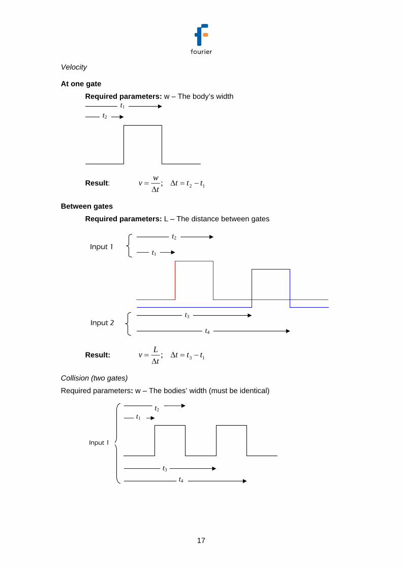
Velocity
At one gate
Required parameters: w – The body’s width
Result: 12; tttt
wv −=ΔΔ
=
t1
t2
t3
t4
Input 1
Input 2
t1 t2
t2 t1

11
Between gates
Required parameters: L – The distance between gates
Result: 13; tttt
Lv −=ΔΔ
=
Acceleration
Between gates
Required parameters: w – The body’s width
Result:
tvva
ttttt
ttwv
ttwv
Δ−
=
−−+=Δ
−=
−=
12
1234
342
121
2
;
t1
t2
t3
t4
Input 1
Input 2
Δt
t1
t2
t3
t4
Input 1
Input 2

12
Working with the Timing Wizard from the Analysis Menu
The Timing Wizard, accessible via the Analysis menu on the on the main MultiLab
toolbar, enables you to easily measure and calculate many types of time events,
including velocity and acceleration, with one or two photo gates.
Connect one photo gate to Input 1 or connect two photo gates to Input 1 and Input 2
in MultiLogPRO and perform the experiment. The Timing Wizard will then guide you
through the analysis.
With the Timing Wizard you can measure sequences of time events at gate one
and/or at gate two, or time events between the two gates. MultiLab can then
calculate the velocity and acceleration. Special options make it easy to measure
velocities in collisions and the time period of a pendulum or any other oscillating
body.
The Timing Wizard can handle multiple events. For example, when a body is
crossing a photo gate several times, applying the Timing Wizard will result in a series
of measurements that match the number of crossings.
1. Display the data that you wish to analyze in the graph window.
2. Click Analysis on the main menu, and then click Timing Wizard to launch
step 1 of the Timing Wizard dialog:
3. Select the desired measurement: Time, Velocity or Acceleration.

13
4. Click Next to move to step 2:
5. Select the desired measuring method.
If required enter the body’s width, or the distance between the gates in cm in the appropriate text box (in velocity and acceleration measurements only).
6. Click Finish to display the results.
7. If you want to change the method or measurement, click Back to return to the
Timing Wizard.
8. To exit the Timing Wizard click OK.
Measuring Methods
The Timing Wizard offers you various methods of analyzing the different
measurements. In some measurements you will be asked to enter the dimension of
the moving body, or the distance between the two photo gates to allow for the
calculation of velocity and acceleration.
The methods depend on the selected measurement:
Time
• At one gate
Measures the time it takes the body to cross the photo gate (between blocking and unblocking the infrared beam)

14
• Between gates
Measures the time it takes the body to move from one photo gate to the second photo gate (between blocking the first and blocking the second infrared beams)
• Pendulum
Measures the time period of an oscillating body (the time interval between the first and the third blockings of the beam)
Velocity
• At one gate
Measures the time it takes the body to cross the photo gate (between blocking and unblocking the infrared beam) and returns the velocity. You should enter the body’s width.
• Between gates
Measures the time it takes the body to move from one photo gate to the second photo gate (between blocking the first and blocking the second infrared beams) and returns the average velocity. You should enter the distance between gates.
• Collisions
Measures the crossing time intervals at each gate and returns the corresponding velocities. You should enter the bodies’ width (the width of the two bodies must be identical)

15
Acceleration
• At one gate
A card with two flags must be attached to the moving body (see figure to the left). The Timing Wizard measures the crossing time intervals of the two flags and returns the acceleration. You should enter the flags width.
• Between gates
Measures the crossing time at the first gate, the time it takes the body to move from one gate to the second gate and the crossing time at the second gate and returns the average acceleration. You should enter the body’s width.

16
Time Schemes and Calculations
Time measurements
At one gate
Result: 12 ttt −=Δ
Between gates
Result: 13 ttt −=Δ
Pendulum (one gate)
Result: 15 ttt −=Δ
t5
t3
t1
t2
t4
t2 t1
t1
t2
t3
t4
Input 1
Input 2
17
Velocity
At one gate Required parameters: w – The body’s width
Result: 12; tttt
wv −=ΔΔ
=
Between gates Required parameters: L – The distance between gates
Result: 13; tttt
Lv −=ΔΔ
=
Collision (two gates)
Required parameters: w – The bodies’ width (must be identical)
t1
t3
t4
Input 1
t1
t2
t3
t4
Input 1
Input 2
t1 t2
t2

18
Result:
782
562
341
121
;
;
ttwv
ttwu
ttwv
ttwu
−=
−=
−=
−=
Acceleration
At one gate Required parameters: w – The flags’ width
Result:
tvva
ttttt
ttwv
ttwv
Δ−
=
−−+=Δ
−=
−=
12
1234
342
121
2
;
t5
t7
Input 2
t8
t1
t2
t3
t4
Input 1
Δt
t6

19
Between gates Required parameters: w – The body’s width
Result:
tvva
ttttt
ttwv
ttwv
Δ−
=
−−+=Δ
−=
−=
12
1234
342
121
2
;
Using the Photo Gate Sensor with the Nova5000 and MultiLab Software
MultiLab software enables you to measure timing events such as Time, Velocity and
Acceleration using the Photo Gate sensor and the data logger’s Timing Wizard.
To use the photo gates together with other sensors operate the Nova5000 as a data
logger and then analyze the photo gate data with the aid of MultiLab's Timing Wizard accessible from the Analysis menu.
Working with the Timing Wizard from the Logger Menu
1. Connect one photo gate to I/O-1 of the Nova5000 or two photo gates, one to I/O-
1 and the other to I/O-2, depending on the type of data you require.
2. From the Logger menu, select Timing Wizard to open the Timer module.
t1
t2
t3
t4
Input 1
Input 2
Δt
20
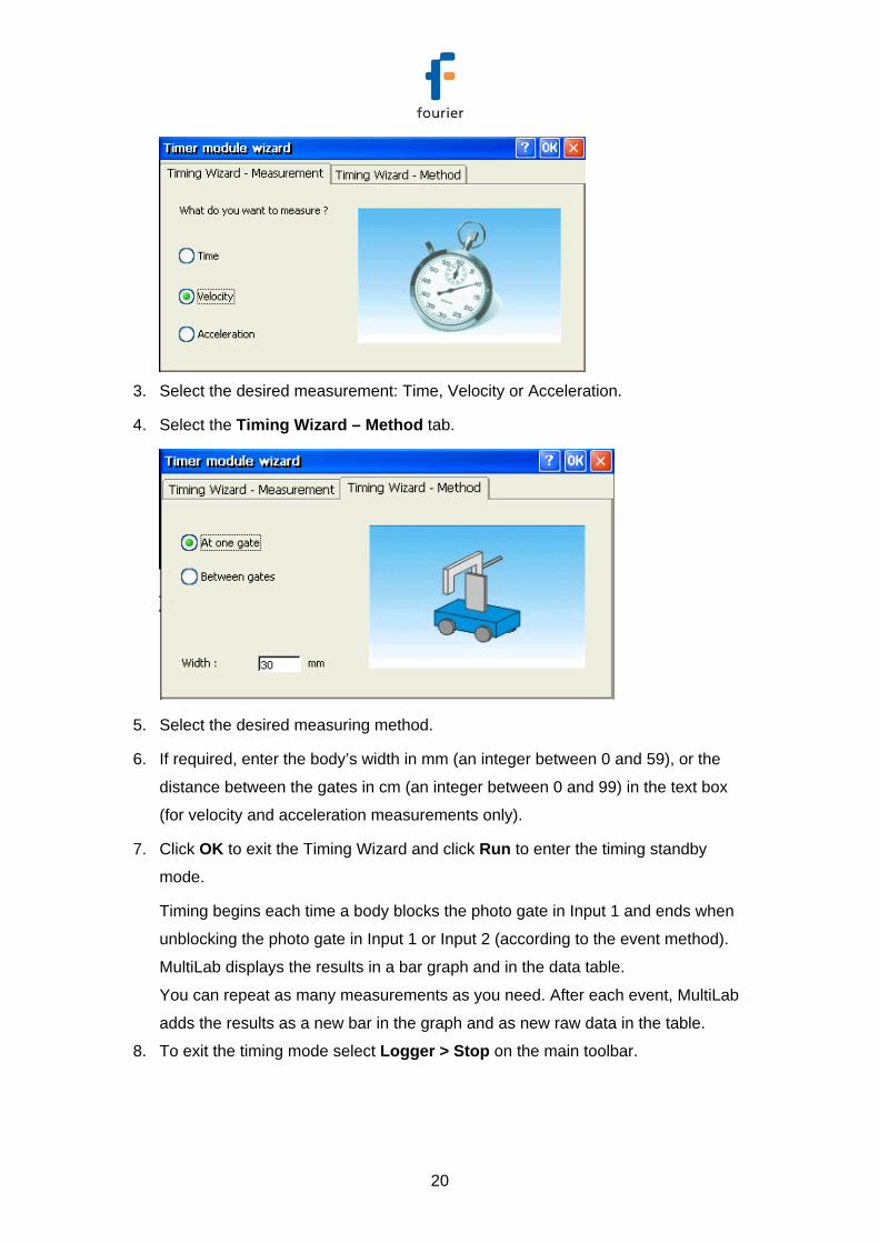
3. Select the desired measurement: Time, Velocity or Acceleration.
4. Select the Timing Wizard – Method tab.
5. Select the desired measuring method.
6. If required, enter the body’s width in mm (an integer between 0 and 59), or the
distance between the gates in cm (an integer between 0 and 99) in the text box
(for velocity and acceleration measurements only).
7. Click OK to exit the Timing Wizard and click Run to enter the timing standby
mode.
Timing begins each time a body blocks the photo gate in Input 1 and ends when
unblocking the photo gate in Input 1 or Input 2 (according to the event method).
MultiLab displays the results in a bar graph and in the data table.
You can repeat as many measurements as you need. After each event, MultiLab
adds the results as a new bar in the graph and as new raw data in the table.
8. To exit the timing mode select Logger > Stop on the main toolbar.
21
The measuring methods, time schemes and calculation are similar to those
described above in the section: Using the Photo Gate Sensor with the MultiLogPRO or TriLink and MultiLab Software.
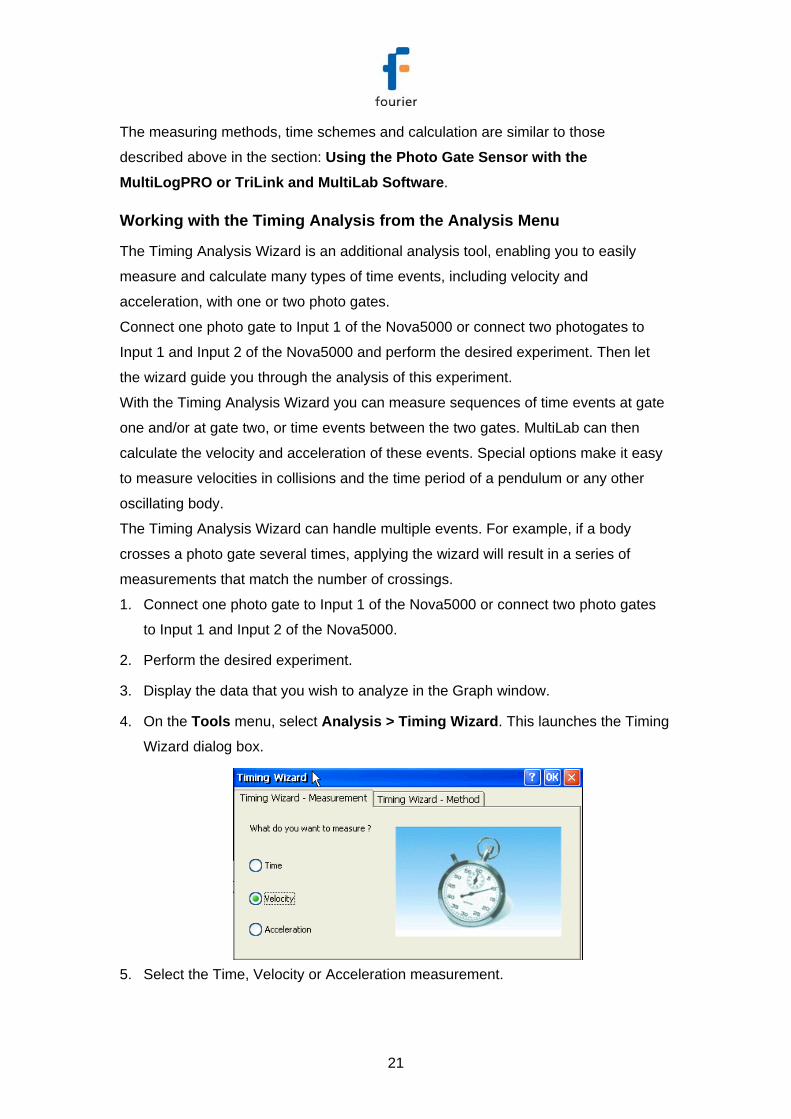
Working with the Timing Analysis from the Analysis Menu
The Timing Analysis Wizard is an additional analysis tool, enabling you to easily
measure and calculate many types of time events, including velocity and
acceleration, with one or two photo gates.
Connect one photo gate to Input 1 of the Nova5000 or connect two photogates to
Input 1 and Input 2 of the Nova5000 and perform the desired experiment. Then let
the wizard guide you through the analysis of this experiment.
With the Timing Analysis Wizard you can measure sequences of time events at gate
one and/or at gate two, or time events between the two gates. MultiLab can then
calculate the velocity and acceleration of these events. Special options make it easy
to measure velocities in collisions and the time period of a pendulum or any other
oscillating body.
The Timing Analysis Wizard can handle multiple events. For example, if a body
crosses a photo gate several times, applying the wizard will result in a series of
measurements that match the number of crossings.
1. Connect one photo gate to Input 1 of the Nova5000 or connect two photo gates
to Input 1 and Input 2 of the Nova5000.
2. Perform the desired experiment.
3. Display the data that you wish to analyze in the Graph window.
4. On the Tools menu, select Analysis > Timing Wizard. This launches the Timing
Wizard dialog box.
5. Select the Time, Velocity or Acceleration measurement.

22
6. Select the Timing Wizard – Method tab.
7. Select one of the measuring methods: At one gate, Between gates or Collision
(two gates).
8. If required, enter the body’s width, or the distance between the gates in cm in the
Width text box.
9. Click OK to display the results.
The measuring methods, time schemes and calculation are similar to those
described above in the section: Using the Photo Gate Sensor with the MultiLogPRO or TriLink and MultiLab Software.
Tips on Using the Timing Wizard
• Attach a flag to the moving body When measuring the motion of a moving cart it is convenient to attach a vertical flag
to the cart (see picture below). You can mount a slotted wooden block on the cart
and insert the flag onto the slot, or use masking tape to attach the flag to one side of
the cart.

23
Use a double flag to measure acceleration at one gate. The width of the two flags
must be the same.
• Use the cursors
Use the cursors to select the graph and data range to which you want to apply
the Timing Wizard.
• Time resolution The time resolution depends on the sampling rate. Use the table below to select
a rate that meats your needs.
Rate
(samples per second) Resolution
10 0.1 s 25 0.04 s 50 0.02 s
100 0.01 s 500 2 ms
1000 1 ms 2000 0.5 ms
20800 0.05 ms • Use the Trigger
For fast events and high sampling rates use the Trigger tool to initiate the data
logging.
An Example of using the Photo Gate Sensor Impulse and Momentum
In this experiment a cart collides with a Force sensor and the change in momentum
is compared to the impulse.
A photo gate is used to measure the velocities of the cart before and after the
collision.

24
Figure 1: Using the photo gate to measure velocities in a collision
Technical Support
Please contact Fourier technical support as follows: Web: http://www.fourier-sys.com/support_support.html Email: [email protected] Consult the FAQs before contacting technical support: http://www.fourier-sys.com/support_faq.html
Copyright and Warranty
All standard Fourier Systems sensors carry a one-year warranty, which states that for
a period of twelve months after the date of delivery to you, it will be substantially free
from significant defects in materials and workmanship.
This Warranty does not cover breakage of the product caused by misuse or abuse.
This Warranty does not cover Fourier Systems consumables such as electrodes,
batteries, EKG stickers, cuvettes and storage solutions or buffers.
Photo Gate Force