
PHASE-OUT...PHASE-OUT 78 200-P-991210-EN-03/09.2015 HDM25 200 − P − 991210 − E − 03 / 10.04...
16
1/220 200 − P − 991210 − E − 03 / 10.04 Monobloc and Sectional Directional Control Valves PHASE-OUT 200-P-991210-EN-03/09.2015
Transcript of PHASE-OUT...PHASE-OUT 78 200-P-991210-EN-03/09.2015 HDM25 200 − P − 991210 − E − 03 / 10.04...

1/220200 − P − 991210 − E − 03 / 10.04
Monobloc and Sectional Directional Control Valves
PHASE-OUT
200-P-991210-EN-03/09.2015

HDM25
65/220200 − P − 991210 − E − 03 / 10.04
6 Monobloc directional control valves HDM25
Contents
6.1 General specifications 66
6.2 Dimensional data 67
6.3 Performances curves 68
6.4 Monobloc bodies 69
6.5 Adjustable direct acting Relief Valve RV 71
6.6 Spool charts 71
6.7 Spool actions 72
6.8 Spool positioners dimensions 72
6.9 Lever styles 73
6.10 Hydraulic−Pneumatic controls 75
6.11 Pneumatic controls 75
6.12 Hydraulic proportional control 76
6.13 Electro−hydraulic controls 77
6.14 Solenoids for pilot electrovalves EHI−EHE 78PHASE-OUT
200-P-991210-EN-03/09.2015

HDM25
66/220200 − P − 991210 − E − 03 / 10.04
6.1 General Specifications
Technical specification
Max flow ratel/min
U.S.G.P.M.10025
Max continuous operatingpressure supply port P
barPSI
2503600
Max intermittent peakpressure Work port A/B
barPSI
3204600
Max back pressuretank port T
barPSI
30430
Oil temperature° C° F
−10 to 8014 to 180
Oil viscosity mm2/s 16 to 75
Oil filtration � �30
Spool leakage at 100 bar (1450 PSI), Temp. 50° C(120° F), viscosity 27 mm2/s
Maximumcm3/min
Cu. In./min16
0.854
Averagecm3/min
Cu. In./min8
0.427
Lower values on demand (to be agreed with our Sales Dpt.)
Number of spools 1 to 2
Adjustable direct operated relief valve(tamper−proof seal available on request)
RV
Load hold check valve in each section LC
6.1.1 Weight
Version kg lb
HDM25/1 5.9 13
HDM25/2 9 19.8
6.1.2 Material specification:
Body: High strength cast−iron.Spool: Hardened steel and chrome platedSeals: Buna �N".
6.1.3 Standard features:
1) Internal load holding check valves (prevent reverseflow through valve when two spools are operated)
2) Parallel circuit3) Balanced interchangeable spools (provides
minimum leakage, smooth operation)4) Wide selection inlets, work ports, and outlets
threaded ports.5) Negative overlapping of the spool.
6.1.4 Optional features available:
1) Open or closed centre positions, 3 or 4 way operations, 3 or 4 position (float position), full
open centre (motor spool) and other spooloptions.
2) Carry over.3) Series connection and tandem4) Complete lever assembly
6.1.5 Symbols:
P: inlet portT: outlet portA/B: work portsH.P.C.O.: carry−overRV: relief valveP1T1: side inlet and outlet ports3.1.0.2: spool positionP: pressure lineT : exhaust lineE: centre line (by pass).
PHASE-OUT
200-P-991210-EN-03/09.2015

HDM25
67/220200 − P − 991210 − E − 03 / 10.04
6.2 Dimensional Data
Ex.: 62 = mm
2.44" = inches
HDM25/1
HDM25/2
T1H.P.C.O.
Pos.2: STROKE − 7 mm. − .28"
Pos.1: STROKE − 7 mm. − .28"Pos.3: STROKE − 7 mm. − .47"
PRESS
PRESS
B
A
0
Float
Pos.2: STROKE − 7.5 mm. − .30"
0Pos.1: STROKE − 7.5 mm. − .30"
B
A
B
A
A
B
TP
RV
P1
A
B
TP
RV
P1
� D
� D
PRESS
PRESS
M10X1.5
1 5/16" − 12
(SAE16)
(see 6.9)
Dimensional data shown in mm and inches.
115
4.53"
164
6.64"PHASE-OUT
200-P-991210-EN-03/09.2015
HDM25
68/220200 − P − 991210 − E − 03 / 10.04
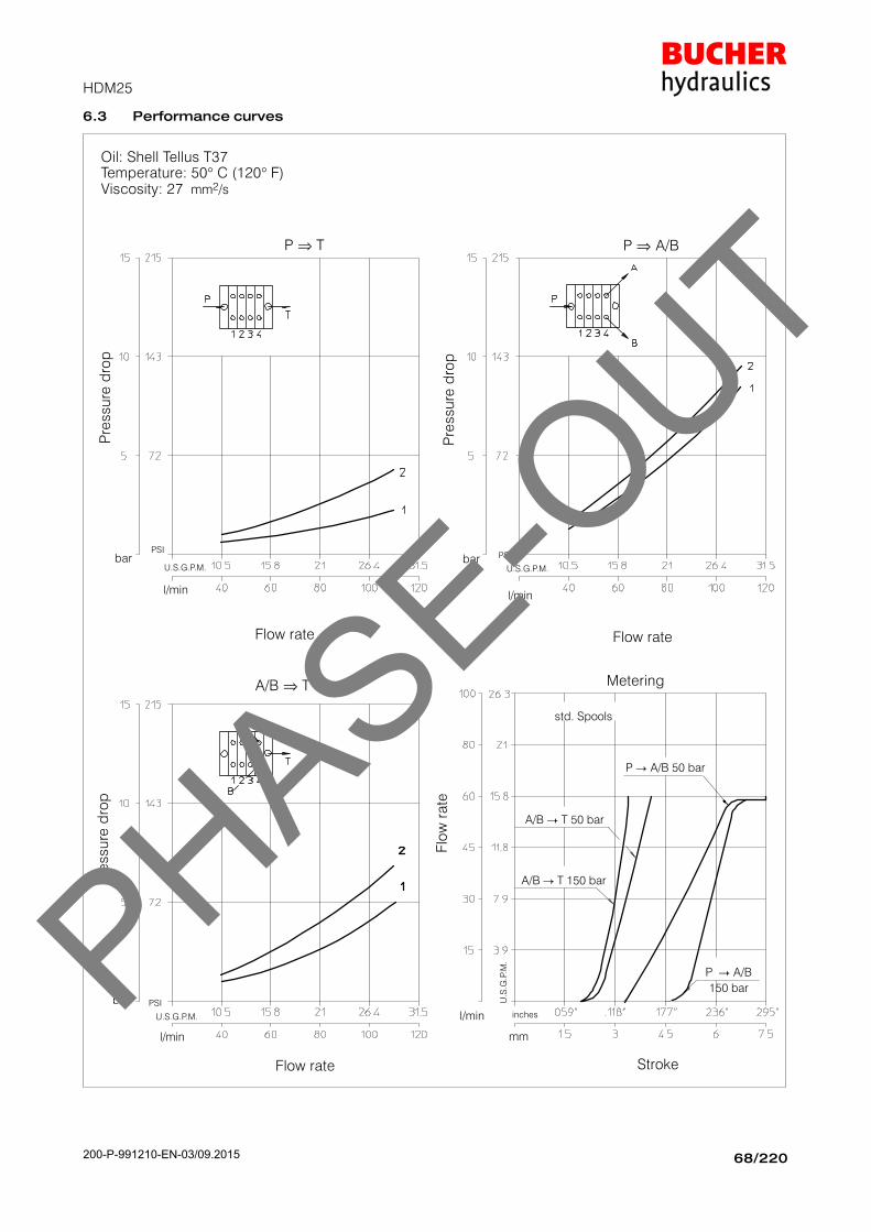
6.3 Performance curves
Oil: Shell Tellus T37Temperature: 50° C (120° F)Viscosity: 27 mm2/s
Flow rate
l/min
bar
Pre
ssure
dro
p
U.S.G.P.M.
PSI
P ⇒ T
std. Spools
Metering
Flow rate
l/min
bar
Pre
ssure
dro
p
U.S.G.P.M.
PSI
Flow rate
l/min
bar
Pre
ssure
dro
p
U.S.G.P.M.
PSI
A/B ⇒ T
P ⇒ A/B
Stroke
A/B � T 150 bar
inches
mm
l/min
A/B � T 50 bar
P � A/B 50 bar
P � A/B
150 bar
Flo
w r
ate
U.S
.G.P
.M.PHASE-O
UT
200-P-991210-EN-03/09.2015

HDM25
69/220200 − P − 991210 − E − 03 / 10.04
6.4 Monobloc bodies
6.4.1 Open centre with P − T − RV (Standard circuits: parallel)
∅ D
Code
HDM25/1
SAE12
M18X1.5
1/2" BSPStd.
SAE10
K01
K04
K03200.9441.4001.0
HDM25/2
K02200.9441.3001.0
3/4" BSP
K05
K01
K04
K03200.9442.4001.0
K02200.9442.3001.0
K05
P
T
RV
6.4.2 Power beyond with P − T − RV − H.P.C.O.(Standard circuits: parallel)
P
T
RV
H.P.C.O.
H.P.C.O.
∅ D
Type/Code
HDM25/1
SAE12
M18X1.5
3/4" BSP
SAE10
K21
K24
K23200.9441.4003.0
HDM25/2
K22200.9441.3002.0
1/2" BSPStd.
K25
K21
K24
K23200.9442.4002.0
K22200.9442.3003.0
K25
Note: Body codes consist of: machined casting, seals, plugs and check valve only. Not to be used for complete valve order.
For availability of −K− bodies without code please contact our Sales Department.
PHASE-OUT
200-P-991210-EN-03/09.2015

HDM25
70/220200 − P − 991210 − E − 03 / 10.04
6.4.3 Open centre with P − T − RV(Optional circuits: series and tandem)
∅ D
Type/Code
Standard
M18X1.5
SAE10
3/4" BSP
1/2" BSPstd.
K31
K34
K33
K32
SAE12 K35
6.4.4 Power beyond with P − T − RV − H.P.C.O.(Optional circuits: series and tandem)
H.P.C.O.
∅ D
Type/Code
Standard
M18X1.5
SAE10
3/4" BSP
1/2" BSPstd.
K51
K54
K53
K52
SAE12 K55
H.P.C.O.
Note: Body codes consist of: machined casting, seals, plugs and check valve only. Not to be used for complete valve order.
For availability of −K− bodies without code please contact our Sales Department.
PHASE-OUT
200-P-991210-EN-03/09.2015

HDM25
71/220200 -- P -- 991210 -- E -- 03 / 10.04
6.5 Adjustable direct acting Relief Valve RV
Fluctuating pressureF
Operating Time
Pea
kP
T
Flow rate
l/min
bar
Pre
ssur
ese
tting
U.S.G.P.M.PSI
RV
P
Relief valve set at 30 l/min (8 U.S.G.P.M.)
06
15
26
60(860)
150(2100)
260(3700)
Yellow(YE)
Green(GR)
Blue(BL)
30 -- 95(400 -- 1300)
96 -- 210(1300 -- 3000)
211 -- 300(3000 -- 4200)
Setting CodeStd. settingbar (PSI)
Springcolour
Pressure set rangebar (PSI)
32320(4600)
Red(RD)
301 -- 400(4200 -- 5700)
*
*
* The maximum operating pressure for each valve series is indicated in the
“Technical specification” at the first page of each valve section.
6.6 Spool charts
Spool scheme Spool features Type
4 way -- 3 positionA/B: blocked
E: open by pass
AAs*
4 way -- 3 positionA/B: blocked
E: closedB
4 way -- 3 positionA/B to tank in neutral
E: open by pass
C*Cs
3 way -- 3 positionB: blocked
E: open by pass
G*Gs
4 way -- 3 positionB: blocked
A: to tank in neutralL
4 way -- 3 position withdifferential spool in 2nd
position**R
3 way -- 3 positionA: blocked
E: open by pass
S*Ss
4 way -- 3 positionseries connection X
4 way -- 3 positionA: to tank in neutral Xc
4 way -- 4 position4th float position Z
** : special body required
* : Hight metering spool (max. flow suggested 50 l/min)PHASE-O
UT
200-P-991210-EN-03/09.2015

HDM25
72/220200 − P − 991210 − E − 03 / 10.04
6.7 Spool positioners
Spool position StrokeType Code
3 1 0 2 mmType Code
� � � 7.5 01 200.9686.1002.0
� � � 7.5 02 200.9686.3002.0
� � � 7.5 03 200.9686.2002.0
� � 7.5 05 200.9686.2004.0
� � 15 06 200.9686.1004.0
� � 7.5 07 200.9686.2007.0
� � 7.5 09 200.9686.1011.0
� � 15 11 200.9686.2009.0
� � � 7.5 19 200.9686.3008.0
� � � 7.5 24 200.9686.5013.0
� � � 7.5 31 200.9686.1054.0
� � � 7.5 46 200.9686.1076.0
� � � 7.5 47 200.9686.1078.0
� � � 7.5 50 200.9686.5020.0
� � � 7.5 56 200.9686.1086.0
� � � 7.5 83 200.9686.1096.0
� � � � 5 − 7 − 7 128 200.9686.4009.0
� Initial hand lever position� Hand lever in detent position� Spring return position of hand lever
Spool position corresponds tohand lever position
Force (F) for spool movement
F (N) Spool position control
350 01 (standard)
280 56
Note: consult factory for different configurations.
6.8 Spool positioner dimensions
Spool positioners01 − 02 − 03 − 05 − 0607 − 09 − 11 − 19 − 56
Spool positioner (Z spool type)
128
Spool positioner83
Microswitch control
31
46
47
Microswitch is operated when the spool is in pos.1
Microswitch is operated when the spool is in pos.2
Microswitch is operated when the spool is in pos.1 and 2The microswitch is supplied only on
customer’s request.PHASE-O
UT
200-P-991210-EN-03/09.2015

HDM25
73/220200 − P − 991210 − E − 03 / 10.04
6.9 Lever styles
TypeL55
37
10
10
TypeL100
M10X1.5
80
TypeL300
M10X1.5
80
001
004
003
002
1857.28
9.84
11.81
13.78 350
300
250
200.7022.2001.0
200.7022.2003.0
200.7022.2004.0
200.7022.2005.0
mminches
Lo
AL Code
Lo
M10X1.5
6.9.1 Safety levers
TypeL47
M10X1.5
37
6
14
.80
"
TypeL46
335
13.19"
M10X1.5
PHASE-OUT
200-P-991210-EN-03/09.2015

HDM25
74/220200 − P − 991210 − E − 03 / 10.04
6.9.2 Remote cable control
LeverSupport
Code200.7609.0013.0 M10X1.5
Optional
200.6772.0048.0
Cables are assembled on the
valve only on request and with an
extra charge.
Cable
200.5441.04002
200.5441.04005
200.5441.04006
200.5441.04007
200.5441.04008200.5441.04009
Cablelength Code
1000 mm1500 mm2000 mm2500 mm3000 mm4000 mm
M10X1.5
L0 AL001
AL004
AL003
AL002
185 7.28
9.84
11.81
13.78350
300
250
200.7022.2001.0
200.7022.2003.0
200.7022.2004.0
200.7022.2005.0
mm inches
LoType Code
Spool Kit
Code 200.9609.0002.0
Optional
6772.0048.0
TypeL142
Code200.7071.2012.0
Only for rod remote control
M10X1.5
6.9.3 Cross joystick for dual axis control
M12X1.75
TypeAL010
Code200.7022.3004.0
Lo
=2
50
TypeL133
Code200.9759.3007.0
Fulcrum
.
Fulcrum
TypeL134
Code200.9759.3007.0
Fulcrum
Stick LeverM12X1.75
(AL010)
Fulcrum
L133−134 is supplied complete
with rubber boot protection
PHASE-OUT
200-P-991210-EN-03/09.2015

HDM25
75/220200 − P − 991210 − E − 03 / 10.04
6.10 Hydraulic−Pneumatic controls ON−OFF
Operating conditionsHydraulicPressure range (bar): Min. 6 − Max. 15
(PSI): Min. 85 − Max. 215PneumaticPressure range (bar): Min. 6 − Max. 10
(PSI): Min. 85 − Max. 145
Type Code
HP 24 200.9686.5013.0
6.11 Pneumatic controls
6.11.1 Pneumatic proportional control
Type Code
PP 151 200.9686.5010.0
6.11.2 Electro−pneumatic control ON−OFF
Electrical dataInsulation class H − 180° C (356° F)Encapsulation material: nylonTemperature range:−10° C to 80° C (14° F to 170° F)Duty cycle: 100% at 68° F ambientVoltage variation: −10% to + 15% of nominalvoltagePower consumption DC − 10 WElectrical connection: DIN43650/A (2P + E)Cable connection PG9Protection class: IP65 (with connector)
Operating conditionsPressure range (bar): Min. 6 − Max. 10
(PSI): Min. 85 − Max. 145Ambient temperature: −10° C to 50° C (14° F to 122° F)Response time: 6 − 8 millisecondsMounting in any position
EP 77
Type
12 VDC 200.9686.6024.0
EP 78
Voltage Code
200.9686.6027.024 VDC
PHASE-OUT
200-P-991210-EN-03/09.2015

HDM25
76/220200 − P − 991210 − E − 03 / 10.04
6.12 Hydraulic proportional control
Joystick adjustment diagram
Type Code
HP 50 200.9686.5020.0
Ou
tle
t p
ressu
re (
ba
r)
30
19
5
Adjustment range (bar): Min. 5 − Max. 30(PSI): Min. 70 − Max. 425
PHASE-OUT
200-P-991210-EN-03/09.2015

HDM25
77/220200 − P − 991210 − E − 03 / 10.04
6.13 Electro−hydraulic controls
6.13.1 Electro−hydraulic control external pilot version ON−OFF
EHE 300
Type
Inlet section 200.9686.6033.0
Description Code
EHE 305 End section 200.9686.6037.0
For solenoid see
chapter 6.14
300 305
EHE 301
Type
Inlet section 200.9686.6051.0
Description Code
301
6.13.2 Electro−hydraulic control external pilot version ON−OFF with pressure reducing valve on inlet manifold
For solenoid see
chapter 6.14
EHE 303
Type
Inlet section 200.9686.6058.0
Description Code
303
EHE 302
Type
Inlet section 200.9686.6032.0
Description Code
EHE 305 End section 200.9686.6037.0
302
305
Mechanical and hydraulic featuresPilot pressure with pressure reducing valve 12 bar (175 PSI). . . . . . . . . . . . . . . . . . . . . . . Pilot flow to each working section: 1 l/min (0.26 USGPM). Min. suggested filtration 25 micron. . . . . . . . . . . . . . . . . . . .
Operating oil temperature min.−30°C− max. 90°C. . . . . . . . min.−22°F − max 194°F
Leakage of pressure reducingvalve (in neutral pos.) 100 ml/min (6.1 in3/min). . . . . . . . . .
PHASE-OUT
200-P-991210-EN-03/09.2015

HDM25
78/220200 − P − 991210 − E − 03 / 10.04
6.14 Solenoids for pilot electrovalves EHE
Wire class F (VDE 0580)
Coil insulation IP65 (DIN 40050)
Duty rating ED 100%
Stabilized temperature 70 �C
Voltage tolerance ± 10%
SupplyNominal
PowerResistance (Ohm) Current (Ampere)
SupplyVoltage
Nominalcoil
voltage
Power(Watt) Ambient
temperatureStabilized
temperatureAmbient
temperatureStabilized
temperature
Coil code
12 V. DC 12 V. DC 18.7 7.7 10.8 1.56 1.11 200.6749.1003.0
24 V. DC 24 V. DC 18.6 31 41.4 0.77 0.58 200.6749.2003.0
24 V. AC 21.6 V. DC 17.3 27 36 0.80 0.60 200.6748.2003.0
110 V. AC 98 V. DC 15.6 630 825 0.157 0.120 200.6748.4003.0
220 V. AC 198 V. DC 15.7 2500 3300 0.08 0.06 200.6748.6003.0
D.C.Part number200.5441.10009
A.C.Part number200.5441.10012
Armour clamp Pg 9
∅ cable 6 − 8 mm
Diodes 1N 4007 GP
Overvoltage protection VDR
Connector type DIN 43650
Number of poles 2 +
Supply voltage max. 220 V
Nom. capacity at contacts 10 Ampere
Max capacity at contacts 16 Ampere
Resistance at contacts ≥ 4 mOhm
Max section of cable 1.5 mm2
Outer materialGlass fibre reinforced
nylon
Protection factor IP65 (DIN 40050)
Insulation class C (VDE 0110)
Temperature range −40� +90�C
PHASE-OUT
200-P-991210-EN-03/09.2015

200 − P − 991210 − E − 03 / 10.04
BUCHER HYDRAULICS www.bucherhydraulics.com
We reserve the right of modification without prior notice.
Germany
Phone +49 7742 85 20
Fax +49 7742 71 16
Switzerland
Phone +41 33 67 26 11 1
Fax +41 33 67 26 10 3
France
Phone +33 389 64 22 44
Fax +33 389 65 28 78
Italy
Phone +39 0522 92 84 11
Fax +39 0522 51 32 11
Austria
Phone +43 6216 44 97
Fax +43 6216 44 97 4
Netherlands
Phone +31 79 34 26 24 4
Fax +31 79 34 26 28 8
UK
Phone +44 24 76 35 35 61
Fax +44 24 76 35 35 72
China
Phone +86 10 64 44 32 38
Fax +86 10 64 44 32 35
USA
Phone +1 262 605 82 80
Fax +1 262 605 82 78
Product Center (Elevator)
Phone +41 41 757 03 33
Fax +41 41 755 16 49
02
/20
01
Id
.Nr.
20
0.5
99
.99
12
08PHASE-O
UT
200-P-991210-EN-03/09.2015


![Booster sets Product Cataloguemedia.ebaraeurope.com/assets/200305-142441-CatalogoGrupp...Q [l/min] U.S.g.p.m 15 10 15 20 20 30 30 40 40 50 50 60 60 70 70 80 80 90 90 100 100 120 120](https://static.fdocuments.in/doc/165x107/5edcc44dad6a402d666793b8/booster-sets-product-q-lmin-usgpm-15-10-15-20-20-30-30-40-40-50-50-60.jpg)


![PERFORMANCES CURVES EVMS 1 - Vogel Pompes · VOGEL POMPES F +41 (0)32 758 72 90 VOGEL PUMPEN info@vogelpompes.ch SAVAG [MPa] 2.4 2.0 1.6 1.2 0.8 0.4 o o [ml 240 160 120 U.S.g.p.m.](https://static.fdocuments.in/doc/165x107/5ed77171da066b0c06210275/performances-curves-evms-1-vogel-pompes-vogel-pompes-f-41-032-758-72-90-vogel.jpg)
