Phase 2-Final
35
Numerical simulation of Fluidic thrust vectoring by transverse injection flow in a De Laval nozzle Under the guidance of Mr. K Ramesh, Assistant Professor, BMSCE Abhiram D 1BM12ME004 Arvind D R 1BM12ME026 Ashvij Narayanan 1BM12ME028 Asish James 1BM12ME029
-
Upload
abhiram-doddi -
Category
Documents
-
view
18 -
download
1
Transcript of Phase 2-Final

Numerical simulation of Fluidic thrust vectoring by transverse injection flow in
a De Laval nozzle
Under the guidance of
Mr. K Ramesh,
Assistant Professor,
BMSCE
Abhiram D 1BM12ME004
Arvind D R 1BM12ME026
Ashvij Narayanan 1BM12ME028
Asish James 1BM12ME029

Objectives
• Design a CD nozzle for shock free supersonic primary exit flow
• Simulation of nozzle in third critical and under-expanded mode of operation
• Create analytical model for thrust vectoring using Shock Vector Control (SVC)
• Design the transverse inlet port based on MFR and SPR iteratively
• Analysis of the performance of SVC for various parameters

Thrust Vectoring
• What is Thrust Vectoring?
• Need for Thrust Vectoring
Source: Numerical simulation of fluidic thrust vectoring
Source: www.nasa.gov

• Types
Source: https://pritamashutosh.wordpress.com

Source: www.nasa.gov
Source: www.america.pink/9k720
• Advantages• Increased payload fraction• Elimination of high temperature flux joints• Reduction of IR signature
• Applications

What is a C-D nozzle?
It is a device used to convert the sub sonic flow to a super sonic flow.
The need for one is because combustion takes place at only sub sonic conditions.
[Source: http://sahil34935.blogspot.in/2013/03/nozzles.html]

Modes of operation
• First critical mode • Second critical mode • Third critical mode
[Source: Fundamentals of Gas dynamics by Zucker 2nd edition]

Nozzle designThe nozzle specifications are as follows:
• Inlet area ratio: 2.0346• Exit area ratio: 6.7877• Length of diverging section(L) obtained was 1.03m
Inlet Throat OutletArea(m2) 0.07068 0.0347388 0.2358
Pressure(bar) 72.377 40.69 1.01Mach 0.3 1 3.5
Source: http://www.math.iitb.ac.in/~neela/cp.pdf
𝐴2
𝐴1=𝑀 1
𝑀 2(1+[(𝛾−1)/2]𝑀 2
2
1+[(𝛾−1)/2]𝑀 12 )
(𝛾+1 )/2(𝛾− 1)
𝑒𝛥𝑠 /𝑅

The converging section is essentially a frustum of a cone
Whose height is about 0.25 to 0.16 times the diverging section length
The design of the divergent section is critical due to the following reasons• The flow should accelerate to super sonic conditions• The flow should be shock free• The flow should achieve the required Mach number

The method uses a time and position dependent PDE.
The coefficient of the position derivative determines whether the PDE is:• Hyperbolic PDE• Parabolic PDE• Elliptical PDE
Method of Characteristics

Methodology
The nozzle is of minimum length.The points of intersection are considered shock pointsThe boundary points are obtained by an iterative process of averaging slopes
[Source: Fundamentals of Gas dynamics by Zucker 2nd edition]

The code was first generated for a rectangular cross section, which expands in one directionThen modifications were made for them to generate a circular profile with expansion in two directions.

Governing Equations
• General governing equations of Compressible flow
Continuity Equation
Momentum Equation
Energy Equation

• Governing equations for laminar inviscid compressible flow
Continuity Equation
Momentum Equation
Energy Equation
Equation of State
Compatibility equations

• Methods of turning Supersonic flow
• Oblique Shock Relation
Prandtl Meyer Compression Source: Fundamentals of Gas dynamics by Zucker
Oblique ShockPrandtl Meyer Expansion

Design of SVC• Design Parameters
• Area• Mass flow rate• Secondary Inlet Port Position
Known NPR and SPR
Transverse injection Area
and Temperature
Transverse injection port
position
Reflecti-ng bow
shock
Get NPR, SPR, As, T and Xs
Source: Numerical simulation of fluidic thrust vectoring

• OpenFOAM• Free Software• C++ Tool Box• Open Source Codes• Entropy Conservation Schemes
• Solver “rhocentralfoam” Compressible Solver Density based Central Upwind Scheme
Numerical Simulation
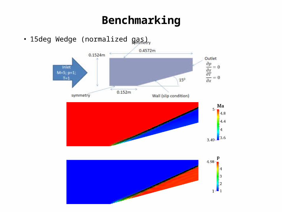
• 15deg Wedge (normalized gas)
Benchmarking

• 150 Ramp (normalized gas)

• Half-Cylinder (un-normalized gas)

• Forward Step (normalized gas)
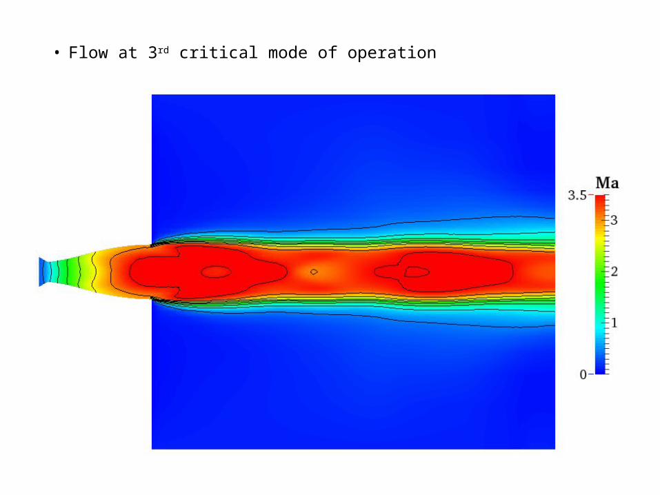
• Flow at 3rd critical mode of operation
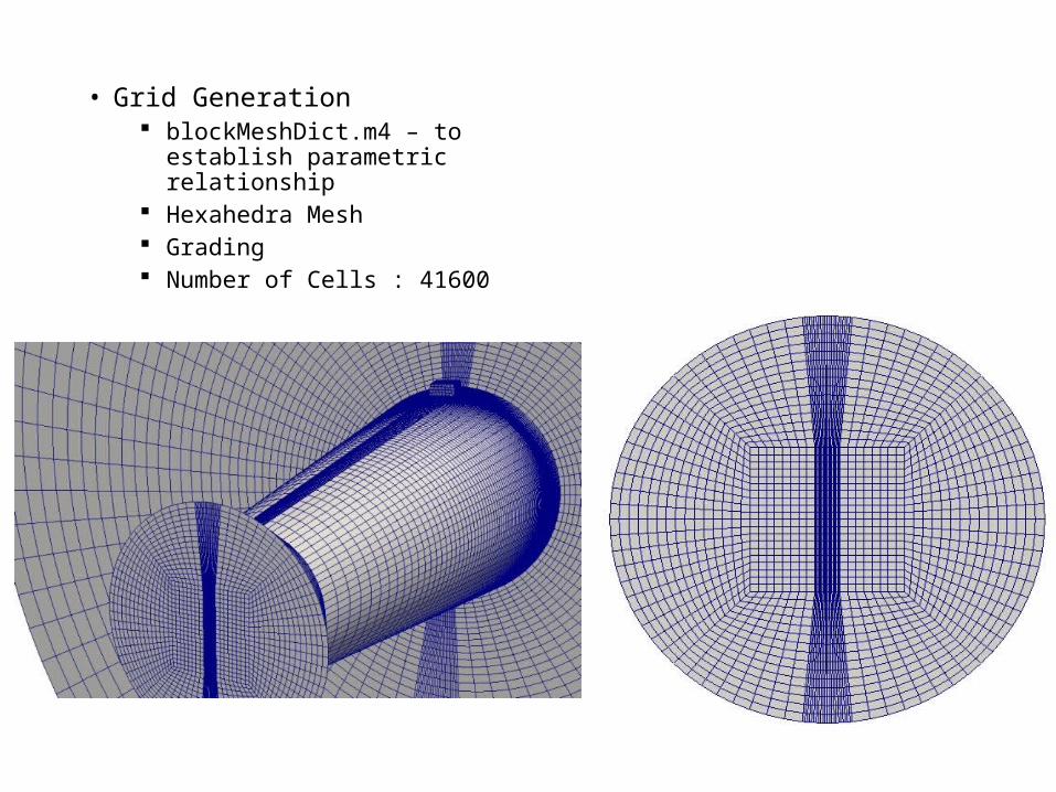
• Grid Generation blockMeshDict.m4 – to establish
parametric relationship Hexahedra Mesh Grading Number of Cells : 41600

• Flow Properties Inviscid flow Laminar flow
• Numerical scheme
Flux scheme KurganovTime scheme EulerGradient Gauss linearDivergence Gauss linearDefault Interpolation Schemes LinearTolerance 1e-09

Boundary conditions • Boundary conditions
Nozzle Pressure Ratio(NPR) of 75 Secondary Pressure Ratio(SPR) was set to 1 Transverse injection for various NPR and SPR values Chamber pressure (static) and temperature was set to ~75bar and
300K

Simulation test cases
• Variation of transverse injection position• Position of secondary inlet tested: 0.6L, 0.85L and 0.9L • Constant MFR of 4.07%• Constant SPR of 0.9
• Variation of Secondary Pressure Ratio• Position of secondary inlet tested at 0.9L • Constant MFR of 4.07%• SPR 0.6, 0.75 and 0.9
• Variation of Secondary Mass Flow Rate• Position of secondary inlet tested at 0.9L • Constant SPR of 0.9• MFR of 1%, 2%, 4%, 8% and 12%

Performance Parameters for SVC
• Deflection Angle
• Vectoring efficiency
• Systems Thrust Ratio
• Thrust Loss

Results
• Variation of transverse injection position

Performance Characteristics for
Transverse Injection Position

• Variation of Secondary Pressure Ratio

Performance Characteristics for
Secondary Pressure Ratio

• Variation of Secondary Mass Flow Rate

Performance Characteristics for
Secondary Mass Flow Rate


Thank You