Permanent Magnet DC-Motors Gleichstrommotoren · 63 Magnetic pulse generator / Magnetische...
74
Permanent Magnet DC-Motors Gleichstrommotoren Series GR / G Baureihe GR / G DIN EN ISO 9001:2008 DIN EN ISO 14001:2004
Transcript of Permanent Magnet DC-Motors Gleichstrommotoren · 63 Magnetic pulse generator / Magnetische...

Permanent Magnet DC-MotorsGleichstrommotoren
Series GR / G Baureihe GR / G
DIN EN ISO 9001:2008
DIN EN ISO 14001:2004

Foreword / Vorwort
To Our Valued Customers,
Dunkermotoren is a world class leader in high quality motion control solutions to meet the ever increasing demands for cost effective and reliable drive solutions. Our comprehensive product range offers the flexibility to provide customized solutions as well as standardized components. The catalog represents Dunkermotoren´s years of engineering excellence.
The Dunkermotoren Team will continue to utilize our outstanding engineering and industrial capabilities to meet the requirements helping you to succeed. Wishing you great success in your business. Nikolaus GräfGeneral Manager
Liebe Kunden,
als führender Hersteller der Antriebstechnik bieten wir Ihnen wirtschaftliche, effiziente und qualitativ hochwertige Komplettlösungen.
Unser umfassendes Produkt- und Leistungsspektrum ermöglicht Ihnen ein hohes Maß an Flexibilität: Ob standardisierte Komponenten oder kundenspezifische Anforderungen - bei uns finden Sie garantiert die passende Lösung.
Mit diesem Katalog können Sie sich einen Überblick über unsere innovativen und richtungsweisenden Produkte verschaffen.
Das Dunkermotoren-Team berät Sie gerne engagiert und kompetent. Denn: Ihr Erfolg ist unser Ziel.
In diesem Sinne freuen wir uns auf Sie und wünschen Ihnen alles Gute.
Ihr Nikolaus GräfGeneral Manager
2

3
Content / Inhalt
2 Foreword / Vorwort
3 Content / Inhalt
4 Why Dunkermotoren? / Gute Gründe
6 Our Product Range / Unser modulares Lieferprogramm
7 Applications / Anwendungen
8 DC Motors GR/G / Kollektor-Gleichstrommotoren GR/G
9 GR/G Selection Guide / GR/G-Auswahlübersicht
10 Technical Information / Technische Informationen
11 Engineering Reference / Auslegung des Antriebs
12 GR 23 4 W
14 G 30.2 4 W
16 G 30.1 6 W
16 G 30.1 S 7 W
18 G 30.0 10 W
18 G 30.0 S 11 W
20 GR 42x25 15 W
22 GR 42x40 20 W
24 GR 51x30 40 W
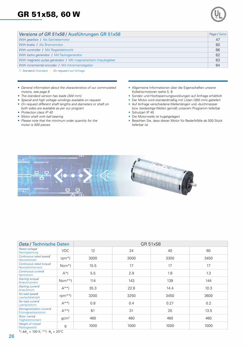
26 GR 51x58 60 W
28 GR 53x30 40 W
30 GR 53x58 60 W
32 GR 53 SI 40 W
32 GR 53 SI 60 W
34 GR 63x25 50 W
36 GR 63x55 100 W
38 GR 63S 130 W
40 GR 63 SI 50 W
40 GR 63 SI 100 W
42 GR 80x40 120 W
44 GR 80x80 240 W
47 Gears / Getriebe
48 PLG
54 SG
60 Brakes for GR/G Motors / Bremsen für GR/G-Motoren
62 Tacho generators / Tachogeneratoren
63 Magnetic pulse generator / Magnetische Impulsgeber
64 Incremental Encoders for GR/G Motors / Inkrementalgeber für GR/G-Motoren
66 Controller / Regelelektroniken
72 Accessories / Zubehör
74 Representatives and Distributors / Vertretungen
© 11/2009
Dunkermotoren GmbH
Printed in Germany
3
4
Why Dunkermotoren? / Gute Gründe
Technology & Customer Focus
At Dunkermotoren, research and develop-ment is a way of life. The company is actively committed to develop key technologies and products that are crucial for its growth. Next-generation technology is in the R&D pipeline today. Product development is focused on innova-tions to help our customers create value and differentiate themselves from competitors.
Innovation und Kundenorientierung
Dunkermotoren ist stolz darauf, vielfach neue Industrie-Standards in der Antriebsbranche geschaffen zu haben. Es ist der Anspruch eines Technologieführers, der Konkurrenz immer einen entscheidenden Schritt voraus zu sein.
Unsere innovativen marktorientierten Antriebslösungen machen unsere Kunden noch erfolgreicher und helfen ihnen, sich mit ihren Produkten positiv von denen der Mitbewerber abzusetzen.
Quality Assurance & Reliability
One of Dunkermotoren´s primary objectives is to offer outstanding quality. In 1991 Dunkermotoren became the world´s first manufacturers of small motors to be certified to ISO 9001. In the meantime, Dunkermotoren has won numerous quality awards.Dunkermotoren regards quality as a compre-hensive process involving all activities in the factory. Our products are manufactured in Ger-many and China on highly automated produc-tion lines. Failure mode and effects analysis during design and development, and fully automated testing integrated in the production line ensure a uniformly high level of quality.
Qualität & Zuverlässigkeit
Antriebslösungen höchster Qualität sind bei Dunkermotoren eine Selbstverständlichkeit, fest verankert in Unternehmensgrundsätzen und Philosophie. Bereits 1991 wurde Dunker-motoren als weltweit erster Hersteller von Kleinmotoren nach ISO 9001 zertifiziert. In der Zwischenzeit folgten zahlreiche weitere Auszeichnungen und Zertifizierungen von Kunden und Vereinigungen.Dunkermotoren versteht Qualität als einen ganzheitlichen Prozess, der sämtliche betrieb- liche Tätigkeiten umfasst. Dunkermotoren produziert in Deutschland und China; hochautomatisierte Fertigungsstrecken und vollautomatische Qualitätskontrollen in den Fertigungslinien gewährleisten ein kon-stant hohes Qualitätsniveau.
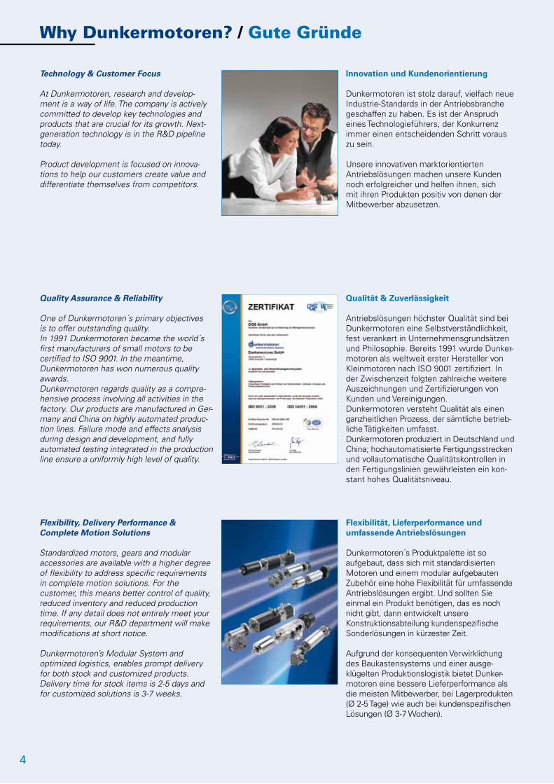
Flexibility, Delivery Performance & Complete Motion Solutions
Standardized motors, gears and modular accessories are available with a higher degree of flexibility to address specific requirements in complete motion solutions. For the customer, this means better control of quality, reduced inventory and reduced production time. If any detail does not entirely meet your requirements, our R&D department will make modifications at short notice. Dunkermotoren’s Modular System and optimized logistics, enables prompt delivery for both stock and customized products. Delivery time for stock items is 2-5 days and for customized solutions is 3-7 weeks.
Flexibilität, Lieferperformance und umfassende Antriebslösungen
Dunkermotoren´s Produktpalette ist so aufgebaut, dass sich mit standardisierten Motoren und einem modular aufgebauten Zubehör eine hohe Flexibilität für umfassende Antriebslösungen ergibt. Und sollten Sie einmal ein Produkt benötigen, das es noch nicht gibt, dann entwickelt unsere Konstruktionsabteilung kundenspezifische Sonderlösungen in kürzester Zeit.
Aufgrund der konsequenten Verwirklichung des Baukastensystems und einer ausge-klügelten Produktionslogistik bietet Dunker-motoren eine bessere Lieferperformance als die meisten Mitbewerber, bei Lagerprodukten (Ø 2-5 Tage) wie auch bei kundenspezifischen Lösungen (Ø 3-7 Wochen).
5
Service & Proximity
Whether home or abroad, Dunkermotoren´s multi-lingual customer service advisers are always on hand. By worldwide local presence of Dunkermotoren individual responsibility is given to the interests of the trading partners - the best drive solution and the most economical application.
Today and in the future, Dunkermotoren will provide a total service to the customers – wherever they are.
Service & Kundennähe
Ob im In- oder Ausland, Dunkermotoren´s Kundenberater sind immer vor Ort präsent und sprechen die Sprache des Kunden. Zur bestmöglichen Berücksichtigung der Interessen des Kunden werden individuelle Schulungen, Betreuung und Beratung durch unsere hochkompetenten Account Manager gewährleistet.
In der Technik wie auch im Vertrieb – Dunkermotoren´s Mitarbeiter scheuen keine Herausforderung, Ihre Anforderungen und Wünsche sind Maßstab für Denken und Handeln.
Sustainable Development
Dunkermotoren is fully aware of its role to promote sustainable development. Therefore it commits itself to pay particular attention to the environment conservation while selecting and using efficiently raw materials and energy necessary for production, supply and use of the product.
In 2002 Dunkermotoren has introduced the environmental management system conforming to the standard ISO 14001.
Umweltschutz und nachhaltige Entwicklung
Dunkermotoren ist sich seiner Rolle, nachhaltige Entwicklung zu fördern, bewusst. Deshalb hat sich die Firma dem Umweltschutz verpflichtet. Ressourcen werden sparsam und effizient eingesetzt.
Als erster Hersteller von Elektrokleinmotoren erhielt Dunkermotoren im Jahre 2002 die Umweltmanagementauszeichnung nach DIN EN ISO 14001.
Therefore / Darum

6
Our Product Range / Unser modulares Lieferprogramm
DC-Motors GleichstrommotorenBrushless DC Motors, Series BG Bürstenlose Gleichstrommotoren, Baureihe BGRated voltage 12-360 VDC Nennspannung 12-360 VDCRated speed 2300-4050 rpm Nenndrehzahl 2300-4050 min-1
Torque 2.3-150 Ncm Drehmoment 2,3-150 NcmPower rating 6-530 W Abgabeleistung 6-530 W
DC Motors, Series GR/G Gleichstrommotoren, Baureihe GR/GRated voltage 3-220 VDC Nennspannung 3-220 VDCRated speed 1500-10000 rpm Nenndrehzahl 1500-10000 min-1
Torque 0.47-65 Ncm Drehmoment 0,47-65 NcmPower rating 3-240 W Abgabeleistung 3-240 W
AC-Motors WechselstrommotorenAC Motors, Series KD/DR Dreh- u. Wechselstrommotoren, Baureihe KD/DRRated voltage 230-400 VAC, 50Hz Nennspannung 230-400 VAC, 50HzPower rating 5-86 W Abgabeleistung 5-86 WTorque 3.6-31.5 Ncm Drehmoment 3,6-31,5 NcmVariants 2/4 pole Varianten 2/4 polig
Venetian Blind- and Positioning Drives, Series D Jalousie- und Stellantriebe, Baureihe DRated voltage 12-24 VDC
110/ 230 VAC 50/60 HzNennspannung 12-24 VDC
110/ 230 VAC 50/60 HzRated speed 11-52 rpm Nenndrehzahl 11-52 min-1
Torque 0.6-20 Nm Drehmoment 0,6-20 Nm Power rating 6-220 W Abgabeleistung 6-220 W
Accessories AnbautenPlanetary Gearboxes, Series PLG Planetengetriebe, Baureihe PLGContinuous torque 0.3-160 Nm Dauerdrehmoment 0,3-160 NmRatio 4:1-710:1 Untersetzungsverhältnis 4:1-710:1
Worm Gearboxes, Series SG Schneckengetriebe, Baureihe SGContinuous torque 1-30 Nm Dauerdrehmoment 1-30 NmRatio 5:1-80:1 Untersetzungsverhältnis 5:1-80:1
Brakes, Series E Bremsen, Baureihe EEncoders, Series RE/TG/ME Inkrementalgeber, Baureihe RE/TG/MEElectronic Control Systems, Series BGE/RS Regelelektroniken, Baureihe BGE/RS

7
Beispiele für Anwendungen
Industrielle Automatisierung
Holzbearbeitung Druckindustrie Papierindustrie Textilmaschinen Lebensmittelmaschinen Verpackungsmaschinen Halbleiterindustrie Kunststoffherstellung Materialhandling Lager und FördertechnikMedizin- und Labortechnik
Türautomation
Sonnenschutz
Motive
Kundenspezifische Lösungen
Geht nicht gibt´s nicht – Kundenspezifische Lösungen von Dunkermotoren! Profitieren Sie vom Know-how des Antriebs-spezialisten. Wir realisieren zielgerichtet, innovativ und anwendungs-orientiert die bestmögliche Antriebseinheit für Sie.
Applications / Anwendungen
Some Applications
Industrial Automation
wood machinery printing industry paper industry textile industry food & beverage machinery packaging machinery semiconductor industry plastics industry material handling mechanical handlingMedical devices & laboratory equipment
Door automation
Sun protection
Motive
Customized Solutions
The impossible takes a little longer – customer specific solutions from Dunkermotoren! Take advantage of the full range of knowledge and experi-ence of our drive specialists. We will develop the best possible drive unit solution for you – innovative, objective and application-oriented.
8
Permanent Magnet DC-Motors GR/G Gleichstrommotoren GR/G
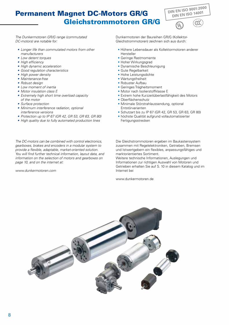
The Dunkermotoren GR/G range (commutated DC-motors) are notable for:
• Longer life than commutated motors from other manufacturers • Low detent torques • High efficiency • High dynamic acceleration • Good regulation characteristics • High power density • Maintenance-free • Robust design • Low moment of inertia • Motor insulation class E • Extremely high short time overload capacity of the motor • Surface protection • Minimum interference radiation, optional interference versions • Protection up to IP 67 (GR 42, GR 53, GR 63, GR 80) • High quality due to fully automated production lines
The DC-motors can be combined with control electronics, gearboxes, brakes and encoders in a modular system to provide a flexible, adaptable, market-oriented solution. You will find further technical information, layout data, and information on the selection of motors and gearboxes on page 10, and on the internet at:
www.dunkermotoren.com
Dunkermotoren der Baureihen GR/G (Kollektor-Gleichstrommotoren) zeichnen sich aus durch:
• Höhere Lebensdauer als Kollektormotoren anderer Hersteller • Geringe Rastmomente • Hoher Wirkungsgrad • Dynamische Beschleunigung • Gute Regelbarkeit • Hohe Leistungsdichte • Wartungsfreiheit • Robuster Aufbau • Geringes Trägheitsmoment • Motor nach Isolierstoffklasse E • Extrem hohe Kurzzeitüberlastfähigkeit des Motors • Oberflächenschutz • Minimale Störstrahlaussendung, optional Entstörvarianten • Schutzart bis zu IP 67 (GR 42, GR 53, GR 63, GR 80) • höchste Qualität aufgrund vollautomatisierter Fertigungsstrecken
Die Gleichstrommotoren ergeben im Baukastensystem zusammen mit Regelelektroniken, Getrieben, Bremsen und Istwertgebern ein flexibles, anpassungsfähiges und marktorientiertes Sortiment.Weitere technische Informationen, Auslegungen und Informationen zur richtigen Auswahl von Motoren und Getrieben erhalten Sie auf S. 10 in diesem Katalog und im Internet bei
www.dunkermotoren.de
DIN EN ISO 9001:2000
DIN EN ISO 14001

9
4.3 W 1.0 Ncm
4 W 1 Ncm
6 W 1.7 Ncm
7 W 2 Ncm
10 W 3 Ncm
11 W 3.7 Ncm
15 W 4 Ncm
20 W 5.7 Ncm
40 W10 Ncm
60W17 Ncm
40 W 10 Ncm
60 W 17 Ncm
50 W 15 Ncm
100 W 28 Ncm
130 W 28 Ncm
120 W 35 Ncm
240 W 63 Ncm
Page/Seite 12 14 16 16 18 18 20 22 24 26 28 30 34 36 38 40 42
TACHO GENERATORS / TACHOGENERATOREN
TG 11 62
TG 52 62
MAGNETIC PULSE GENERATOR / MAGNETISCHE IMPULSGEBER
MG 2 63
ME 52 63
ME 80 63
INCREMENTAL ENCODERS / INKREMENTALGEBER
RE 20 64
RE 30 64
RE 56 64
GEARBOXES / GETRIEBE
PLG 24 (0.3 - 0.6 Nm) 48
PLG 30 (0.3 - 1.8 Nm) 48
PLG 30 H (0.3 - 1.8 Nm) 48
PLG 32 (0.4 - 4 Nm) 48
PLG 32 H (0.4 - 4 Nm) 48
PLG 42 K (0.7 - 3 Nm) 48
PLG 42 S (3.5 - 14 Nm) 49
PLG 52 (1.2 - 24 Nm) 49
PLG 52 H (1.2 - 24 Nm) 49
PLG 60 (5 - 25 Nm) 49
PLG 63 (15 - 100 Nm) 49
PLG 75 (25 - 160 Nm) 49
SG 45 (0.25 - 0.75 Nm) 54
SG 62 (1 - 1.5 Nm) 54
SG 65 (4 Nm) 54
SG 80 (2 - 10 Nm) 54
SG 120 (8 - 30 Nm) 54
BRAKES / BREMSEN
E 38 R 60
E 46 A 60
E 90 R 60
E 100 R 60
E 100 A 60
ELECTRONIC CONTROL SYSTEMS / REGEL-ELEKTRONIKEN
SI (4Q)Integral Servo ControllerServoregler integriert
32/ 40
RS 200 66
BGE 3508 / 6005* 68
BGE 3515 / 6010* 70
ACCESSORIES / ZUBEHÖR
MiscellaneousVerschiedenes
72
GR
23
G 3
0.2
G 3
0.1
G 3
0.1
SG
30.
0G
30.
0 S
GR
42x2
5G
R 42
x40
GR
51x3
0G
R 51
x58
GR
63X
25G
R 63
X55
GR
80X
40G
R 80
X80
GR/G Selection Guide GR/G-Auswahlmöglichkeiten
GR
53X
30G
R 53
X58
n Standard / Standard n On request / auf Anfrage
* For G/ GR motors with incremental encoder RE 30 attached * Für Motoren mit angebautem Inkrementalgeber RE 30
GR
63SX
55
10
Technical Information / Technische Information
PERFORMANCE DATA
Performance figures given in the tables are measured in accordance with EN60034. These figures are based on the assumption that the motor is freestanding and that certain other theoretical conditions are fulfilled. In a real application the rated torque of a motor will often be considerably higher, since by assembly conditions and circulation a higher heat dissipation is achieved.
For many applications, it is sufficiently accurate to take the most important data from the mo-tor characteristic diagrams and data tables. Although tolerances and temperature influences are not taken into account, the data is accurate enough for approximate calculations. The degree of protection quoted relates only to the housing – adequate sealing of the shaft is the responsibility of the customer.
- Nominal voltage UN (VDC) The DC voltage that is applied to the motor as a supply voltage. All rated data in our catalogs are with reference to this voltage. Motor applications are, however, not restricted to this voltage.
- Rated torque MN (Ncm) The torque that can be produced by the motor, operating continuously, in an ambient temperature of 20°C.
- Rated speed nN (min-1) The speed of the motor when it is operating at rated torque (5).
- Rated current IN (A) The current drawn from a DC source when the motor is operating at rated torque (6).
- Starting current IA (A) The current required to produce the starting torque. For motors with electronics, the starting current may be higher than the permissible peak current (4).
- Starting torque MA (Ncm) The maximum torque the motor can produce (2).
- Rated power PN (W) The output power which the motor can produce continuously; it is calculated from rated speed and rated torque.
- Moment of inertia of rotor JR (gcm2) The moment of inertia of the rotor is the factor that determines the dynamic properties of a motor.
- Max. permissible voltage range Umax (VDC) The minimum and maximum permissible input voltage for electronics or motors with integral electronics.
- Recommended speed control range nmax (min-1) The regulated speed range within which rotor position sensing by Hall sensors ensures a smooth torque curve. As a rule, this range can be extended by installing a rotary encoder.
The data in this catalog contain product specifications, but are not a guarantee of particular properties. The stated values are subject to tolerances. Any supplementary information and safety instructions given in the operating manual must be observed with no exceptions.
We reserve the right to make technical changes and to restrict availability.
LEISTUNGSDATEN
In den Datentabellen sind die Werte gemessen nach EN60034 ange-geben. Diese Werte basieren auf der Annahme eines freistehenden Motors und auf weiteren theoretischen Gegebenheiten. Im reellen Einsatzfall liegt das Nenndrehmoment des Motors oftmals wesentlich höher, da durch Einbaubedingungen und Zirkulation eine höhere Wärmeabfuhr erzielt wird.
Den Motordiagrammen und Datentabellen können die für viele Anwen-dungen wichtigsten Daten entnom-men werden. Obwohl Toleranzen und Temperatureinflüsse nicht berück-sichtigt sind, reichen die Werte für überschlagsmässige Betrachtungen aus. Die angegebenen Schutzarten beziehen sich nur auf die Gehäuse. Die Abdichtung der Welle ist vom Kunden vorzunehmen.
- Nennspannung UN (VDC) Die Gleichspannung, die als Versorgungsspannung an den Motor angelegt wird. Auf diese Spannung beziehen sich alle Nenndaten in den Katalogen. Die Motoranwendung ist jedoch nicht auf diese Spannung beschränkt.
- Nenndrehmoment MN (Ncm) Das Moment, das der Motor bei einer Umgebungstemperatur von 20°C im Dauerbetrieb abgeben kann.
- Nenndrehzahl nN (min-1) Die Drehzahl, die sich bei Abgabe des Nenndrehmoments einstellt (5).
- Nennstrom IN (A) Der Strom, der der Gleichspannungsquelle entnommen wird, wenn der Motor bei Nenndrehmoment betrieben wird (6).
- Anlaufstrom IA (A) Der Strom, der fließt, um das Anlaufmoment zu erzeugen. Bei Motoren mit Elektronik kann der Anlaufstrom höher sein als der zulässige Spitzenstrom (4).
- Anlaufmoment MA (Ncm) Das Moment, welches der Motor maximal erzeugen kann (2).
- Nennleistung PN (W) Die Abgabeleistung des Motors, welche er dauerhaft erzeugen kann; berechnet aus Nenndrehzahl und Nenndrehmoment.
- Läufermassenträgheitsmoment JR (gcm2) Massenträgheitsmoment des Rotors und bestimmende Größe für die dynamischen Eigenschaften des Motors. - Max. zulässiger Spannungsbereich Umax (VDC) Die minimal und maximal zulässige Eingangsspannung bei Elektroniken oder Motoren mit integrierter Elektronik.
- Empfohlener Drehzahlregelbereich nmax (min-1) Der Drehzahlregelbereich in dem bei Rotorlageerkennung durch Hallsensoren ein glatter Drehmomentverlauf steuerbar ist. Durch Anbringung eines Inkrementalencoders kann dieser Bereich in der Regel erweitert werden.
Die Angaben in diesem Katalog enthalten Spezifikationen der Produkte, nicht aber die Zusicherung von Eigenschaften. Die genannten Werte unterliegen Toleranzen. Die im Betriebshandbuch angegebenen Ergänzungen und Sicherheitshinweise sind unbedingt zu beachten.
Liefermöglichkeiten und technische Änderungen vorbehalten.
�
�
N = f (M)
Destroying operationZerstörende Betriebszustände
η
-0.8 0 0.8 1.6 2.4 3.2 4 4.8 5.6 6.4 7.2 8 Ncm
curre
nt/S
trom
I (A)
2.8
2.4
2
1.6
1.2
0.8
0.4
0
70
60
50
40
30
20
10
0effic
iency
/Wirk
ungs
grad
η (%
)
rated
spee
d/Dr
ehza
hl n (
rpm)
7000
6000
5000
4000
3000
2000
1000
0
J = f (M)
MN
Continuous operationDauerbetrieb
Cyclic operationZyklischer Betrieb
�
�
�
�
Mmax

11
Engineering Reference / Auslegung des Antriebs
MOTOR CHARACTERISTIC DIAGRAMS
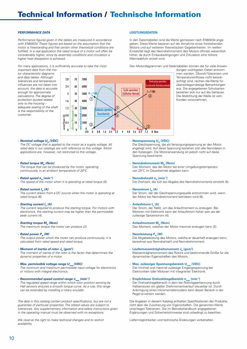
- Speed curve (blue)This curve shows the speed characteristic at constant voltage. Its end points are the no-load speed n0 (1) and the theoretical starting torque MA (2).
- Current curve (black)The current curve shows the relationship between current and torque. Its end points are the no-load current I0 (3) and the starting current IA (4).
- Efficiency curve (green)The efficiency is the relationship between the mechanical power output and the electrical power input.The curve shows the efficiency with the motor in cold condition; as the motor warms up, the curve shifts accordingly.
- Rated torque MN , Starting torque Mmax The rated torque (red) is the limit of the continuous operation region (shaded blue). In the region between the rated torque and the maximum permissible torque, the motor must only be used intermittently (shaded orange). Operating conditions above the maximum permissible torque result in demagnetization of the permanent magnets (shaded red).
ENGINEERING REFERENCE
In the wide range of Dunkermotoren products, you will find a suitable drive for almost any requirement in powers ranging from 1 - 530 Watt. Please also note our other product lines and catalogs (Brushless DC Motors, AC motors).
The following points should be taken into account when selecting motors and gearboxes: - Which type of operation is required (continuous, intermittent or periodic operation)? - What is the working life expected of the motor? - What torque and speeds are required? - How much space is available for the motor? - How high is the available voltage? DC or AC? - Are there special environmental conditions (temperature, humidity, vibration, ...)? - To what degree can heat from the motor be disposed of? - Are there exceptional axial and radial shaft loads to consider? - What demands are made of the motor control electronics? - Is the motor to be controlled online via a bus system? - Do you need a brake, an encoder or a non-reversing device?
By dimensioning a suitable motor, determining the required torque plays a decisive role in avoiding thermal overload of the motor in service. In the assembly of a drive system consisting of motor and control elec-tronics, it is important to ensure that permissible values for the motor are not exceeded by outputs from the electronics.
Depending on the speed of rotation required, a motor or a motor-gearbox combination may be selected. The choice of a reduction gearbox will largely depend on the recommended maximum torque in continuous operation. For intermittent duty, loading above the rated torque is possible. When choosing a motor after deciding on the gearbox, the following applies:
Mmotor = Mgearbox / (i x h)
We will be pleased to carry out a precise adaptation of a motor to your service conditions.
MOTORDIAGRAMME
- Drehzahlkennlinie (blau)Diese Kennlinie beschreibt das Drehzahlverhalten bei konstanter Span-nung. Deren Endpunkte zeigen die Leerlaufdrehzahl n0 (1) und das theoretische Anlaufmoment MA (2).
- Stromkennlinie (schwarz)Die Stromkennlinie stellt die Äquivalenz von Strom und Drehmoment dar. Deren Endpunkte zeigen den Leerlaufstrom I0 (3) und den Anlauf-strom IA (4).
- Wirkungsgradkennlinie (grün)Der Wirkungsgrad beschreibt das Verhältnis von abgegebener mechanischer Leistung zu aufgenommener elektrischer Leistung.Die Kennlinien beziehen sich auf den Kaltzustand des Motors und ver-schieben sich entsprechend bei zunehmender Erwärmung des Motors.
- Nenndrehmoment MN , Anlaufdrehmoment Mmax Das Kriterium Nenndrehmoment (rot) begrenzt den Dauerbetriebs-bereich (blau schattiert). Im Bereich zwischen Nenndrehmoment und max. zulässigem Drehmoment darf der Motor nur kurzzeitig betrieben werden (orange schattiert). Betriebszustände über dem max. zulässigen Drehmoment führen zur Entmagnetisierung der Dauermagneten (rot schattiert).
AUSLEGUNG DES ANTRIEBS
In Dunkermotoren´s breiter Produktpalette finden Sie für nahezu jede Anforderung einen passenden Antrieb im Leistungsbereich von 1 - 530 Watt. Bitte beachten Sie auch unsere weiteren Produktlinien und -kataloge (Bürstenlose DC-Elektronikmotoren, Wechselstromotoren).
Folgende Punkte sollten bei der Auswahl von Motor und Getriebe berücksichtigt werden: - Welche Betriebsart liegt vor (Dauer-, Kurzzeit- oder Aussetzbetrieb)? - Welche Lebensdauer wird gefordert? - Welches Drehmoment und welche Drehzahl werden benötigt? - Wie viel Raum ist für den Motor verfügbar? - Wie hoch ist die verfügbare Spannung? Gleich- oder Wechselspannung? - Gibt es besondere Umgebungseinflüsse (Temperatur, Feuchtigkeit, Vibration, ...)? - In welchem Umfang wird die Motorwärme abgeleitet? - Müssen außergewöhnliche axiale und radiale Wellenbelastungen berücksichtigt werden? - Welchen Steuerungsanforderungen muss die Steuerungselektronik des Motors genügen? - Werden die Motoren online über ein Bussystem angesteuert? - Benötigen Sie eine Bremse, einen Encoder oder eine Rücklaufsperre?
Für die Auslegung des geeigneten Motors spielt die Ermittlung des effektiven Drehmomentes die entscheidende Rolle, um zu verhindern, dass der Motor im Betrieb thermisch überlastet wird. Für die Zusam-menstellung eines Antriebssystems aus Motor und Betriebselektronik ist zu berücksichtigen, dass die für den Motor zulässigen Werte durch die Elektronik nicht überschritten werden.
Je nach gewünschter Drehzahl wird man sich entweder für einen Motor oder einen Getriebemotor entscheiden. Die Wahl des Untersetzungs-getriebes richtet sich nach dem empfohlenen maximalen Drehmoment bei Dauerbetrieb. Bei kurzzeitigem Betrieb sind auch Belastungen über dem Nennmoment möglich. Zur Auswahl des Motors nach Festlegung des Getriebes gilt:
MMotor = MGetriebe / (i x h)
Gerne erfolgt auf Anfrage eine exakte Anpassung des Motors an Ihre Betriebsbedingungen.
12
preliminary data / vorläufige Daten
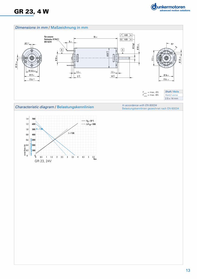
GR 23, 4 W
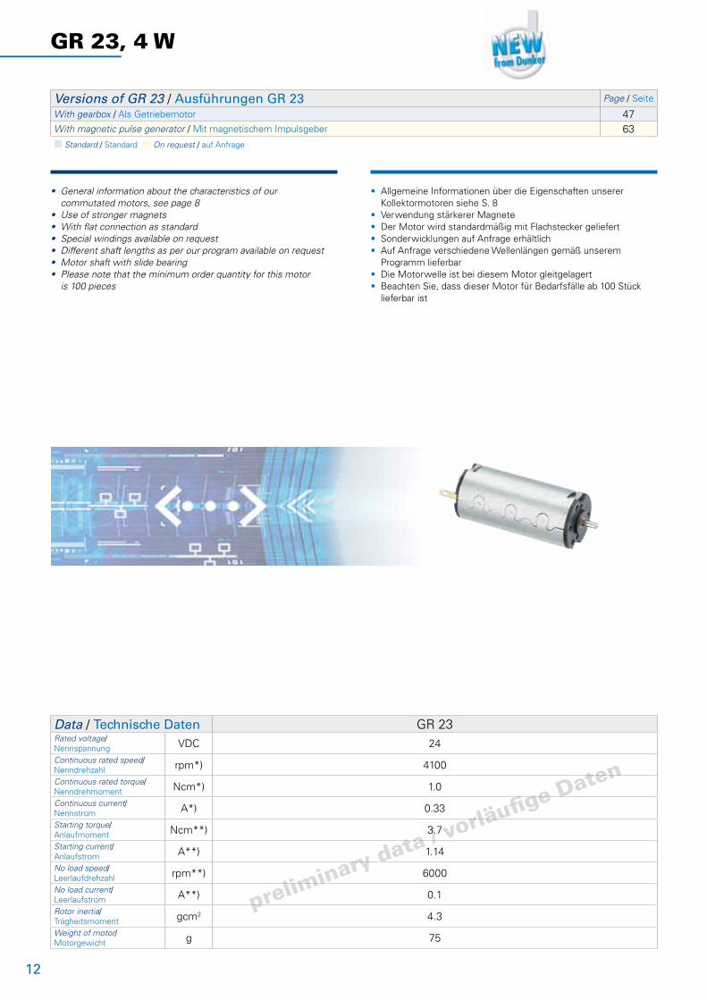
• General information about the characteristics of our commutated motors, see page 8• Use of stronger magnets• With flat connection as standard • Special windings available on request• Different shaft lengths as per our program available on request• Motor shaft with slide bearing• Please note that the minimum order quantity for this motor is 100 pieces
• Allgemeine Informationen über die Eigenschaften unserer Kollektormotoren siehe S. 8• Verwendung stärkerer Magnete• Der Motor wird standardmäßig mit Flachstecker geliefert• Sonderwicklungen auf Anfrage erhältlich• Auf Anfrage verschiedene Wellenlängen gemäß unserem Programm lieferbar• Die Motorwelle ist bei diesem Motor gleitgelagert• Beachten Sie, dass dieser Motor für Bedarfsfälle ab 100 Stück lieferbar ist
Versions of GR 23 / Ausführungen GR 23 Page / Seite
With gearbox / Als Getriebemotor 47With magnetic pulse generator / Mit magnetischem Impulsgeber 63n Standard / Standard n On request / auf Anfrage
Data / Technische Daten GR 23Rated voltage/Nennspannung VDC 24
Continuous rated speed/Nenndrehzahl rpm*) 4100
Continuous rated torque/Nenndrehmoment Ncm*) 1.0
Continuous current/Nennstrom A*) 0.33
Starting torque/Anlaufmoment Ncm**) 3.7
Starting current/Anlaufstrom A**) 1.14
No load speed/Leerlaufdrehzahl rpm**) 6000
No load current/Leerlaufstrom A**) 0.1
Rotor inertia/Trägheitsmoment gcm2 4.3
Weight of motor/Motorgewicht g 75
13
17.5
±0.5
Ø 16 ±0.1
17.6 + 0.1
45°
Ø 1.
8±0.
05
Ø 10
- 0.0
5
A
A
0.03
0.0550 ±0.3
1.5 -0.1
+0.63 - 0.4
88 ±0.5
+ 0.3
Ø 23
- 0.2
1.5 - 0.1
+0.414 - 0.6
A
Ø 10
-0.0
5
Flat connectorFlachstecker A2.8x0.5 DIN 46244
B
Ø 1.
8±0.
05
Ø 13.2±0.07
Ø 17±0.1
17.6 +0.4
Ø 2 +0.1
Ø 2.
5q5
GR 23, 4 W
Dimensions in mm / Maßzeichnung in mm
0 0.5 1 1.5 2 2.5 3 3.5 4 4.5 5 5.5Ncm
7000
6000
5000
4000
3000
2000
1000
0
1.4
1.2
1.0
0.8
0.6
0.4
0.2
0 rated
spee
d/Dr
ehza
hl n (
rpm)
curre
nt/S
trom
I (A)
N = f (M)
J = f (M)
ϑR = 20°C
W= 100K
Characteristic diagram / Belastungskennlinien In accordance with EN 60034 Belastungskennlinien gezeichnet nach EN 60034
Shaft / Welle front / vorne
2.5 x 14 mm
GR 23, 24V
Faxial = max. 4NFradial = max. 8N

14
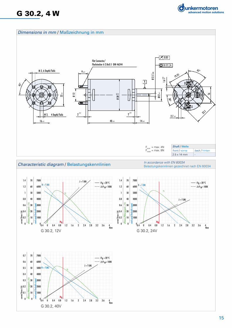
G 30.2, 4 W
Versions of G 30.2 / Ausführungen G 30.2 Page / Seite
With gearbox / Als Getriebemotor 47With brake / Als Bremsmotor 60With tacho generator / Mit Tachogenerator 62With magnetic pulse generator / Mit magnetischem Impulsgeber 63With incremental encoder / Mit Inkrementalgeber 64n Standard / Standard n On request / auf Anfrage
Data / Technische Daten G 30.2Rated voltage/Nennspannung VDC 12 24 40
Continuous rated speed/Nenndrehzahl rpm*) 2900 3000 3500
Continuous rated torque/Nenndrehmoment Ncm*) 1 1 1
Continuous current/Nennstrom A*) 0.6 0.31 0.21
Starting torque/Anlaufmoment Ncm**) 2.8 3 3.27
Starting current/Anlaufstrom A**) 1.4 0.77 0.55
No load speed/Leerlaufdrehzahl rpm**) 4900 5000 5400
No load current/Leerlaufstrom A**) 0.145 0.076 0.054
Rotor inertia/Trägheitsmoment gcm2 11 11.5 11
Weight of motor/Motorgewicht g 80 80 80
*) DJw = 100 K; **) JR = 20°C
• General information about the characteristics of our commutated motors, see page 8• With flat connection as standard, lead versions are available• Different shaft lengths as per our program available on request • The standard version has a slide bearing motor shaft• Please note that the minimum order quantity for this motor is 100 pieces
• Allgemeine Informationen über die Eigenschaften unserer Kollektormotoren siehe S. 8• Der Motor wird standardmäßig mit Flachstecker geliefert. Litzenversionen sind lieferbar• Auf Anfrage verschiedene Wellenlängen gemäß unserem Programm lieferbar• In der Standardausführung ist die Motorwelle gleitgelagert• Beachten Sie, dass dieser Motor für Bedarfsfälle ab 100 Stück lieferbar ist
15
Flat Connector/Flachstecker A 2.8x0.5 DIN 46244
16 ±0.1
M 3, 6 Depth/Tiefe
22±0
.1
45°
M 3, 4 Depth/Tiefe
Ø 12
9 ±0.5
2+0.5
2+0.5
14 ±0.540 ±0.5
+0.4
Ø 30
-0.2
A
0 Ø
2.5 -0.
008
Ø12+
0.1
0.05
0.12 A
+0.05
1.6 -0.
1 19.25
45°
16
23.5
2.7 ±0.1
30°
-0.4 0 0.4 0.8 1.2 1.6 2 2.4 2.8 3.2 3.6 4Ncm
7000
6000
5000
4000
3000
2000
1000
0
70
60
50
40
30
20
10
0
1.4
1.2
1
0.8
0.6
0.4
0.2
0 rated
spee
d/Dr
ehza
hl n (
rpm)
effic
iency
/Wirk
ungs
grad
η (%
)
curre
nt/S
trom
I (A)
MN
N = f (M)
J = f (M)
η
ϑR = 20°C
W= 100K
-0.4 0 0.4 0.8 1.2 1.6 2 2.4 2.8 3.2 3.6 4Ncm
7000
6000
5000
4000
3000
2000
1000
0
70
60
50
40
30
20
10
0
1.4
1.2
1
0.8
0.6
0.4
0.2
0 rated
spee
d/Dr
ehza
hl n (
rpm)
effic
iency
/Wirk
ungs
grad
η (%
)
curre
nt/S
trom
I (A)
MN
N = f (M)J = f (M)
η
ϑR = 20°C
W= 100K
-0.4 0 0.4 0.8 1.2 1.6 2 2.4 2.8 3.2 3.6 4Ncm
7000
6000
5000
4000
3000
2000
1000
0
70
60
50
40
30
20
10
0
0.7
0.6
0.5
0.4
0.3
0.2
0.1
0 rated
spee
d/Dr
ehza
hl n (
rpm)
effic
iency
/Wirk
ungs
grad
η (%
)
curre
nt/S
trom
I (A)
MN
N = f (M)J = f (M)
η
ϑR = 20°C
W= 100K
Shaft / Welle front / vorne back / hinten
2.5 x 14 mm -
G 30.2, 4 W
Dimensions in mm / Maßzeichnung in mm
Characteristic diagram / Belastungskennlinien In accordance with EN 60034 Belastungskennlinien gezeichnet nach EN 60034
G 30.2, 12V G 30.2, 24V
G 30.2, 40V
Faxial = max. 4NFradial = max. 8N
16
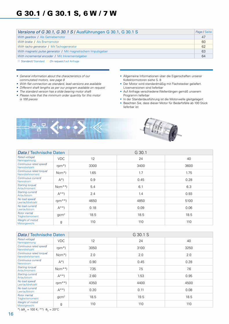
G 30.1 / G 30.1 S, 6 W / 7 W
• General information about the characteristics of our commutated motors, see page 8• With flat connection as standard, lead versions are available• Different shaft lengths as per our program available on request • The standard version has a slide bearing motor shaft• Please note that the minimum order quantity for this motor is 100 pieces
• Allgemeine Informationen über die Eigenschaften unserer Kollektormotoren siehe S. 8• Der Motor wird standardmäßig mit Flachstecker geliefert. Litzenversionen sind lieferbar• Auf Anfrage verschiedene Wellenlängen gemäß unserem Programm lieferbar• In der Standardausführung ist die Motorwelle gleitgelagert• Beachten Sie, dass dieser Motor für Bedarfsfälle ab 100 Stück lieferbar ist
Versions of G 30.1, G 30.1 S / Ausführungen G 30.1, G 30.1 S Page / Seite
With gearbox / Als Getriebemotor 47With brake / Als Bremsmotor 60With tacho generator / Mit Tachogenerator 62With magnetic pulse generator / Mit magnetischem Impulsgeber 63With incremental encoder / Mit Inkrementalgeber 64n Standard / Standard n On request / auf Anfrage
Data / Technische Daten G 30.1Rated voltage/Nennspannung VDC 12 24 40
Continuous rated speed/Nenndrehzahl rpm*) 3300 3400 3600
Continuous rated torque/Nenndrehmoment Ncm*) 1.65 1.7 1.75
Continuous current/Nennstrom A*) 0.9 0.45 0.28
Starting torque/Anlaufmoment Ncm**) 5.4 6.1 6.3
Starting current/Anlaufstrom A**) 2.4 1.4 0.93
No load speed/Leerlaufdrehzahl rpm**) 4650 4850 5100
No load current/Leerlaufstrom A**) 0.18 0.09 0.06
Rotor inertia/Trägheitsmoment gcm2 18.5 18.5 18.5
Weight of motor/Motorgewicht g 110 110 110
Data / Technische Daten G 30.1 SRated voltage/Nennspannung VDC 12 24 40
Continuous rated speed/Nenndrehzahl rpm*) 3050 3100 3250
Continuous rated torque/Nenndrehmoment Ncm*) 2.0 2.0 2.0
Continuous current/Nennstrom A*) 0.90 0.45 0.28
Starting torque/Anlaufmoment Ncm**) 7.35 7.5 7.6
Starting current/Anlaufstrom A**) 2.60 1.53 0.95
No load speed/Leerlaufdrehzahl rpm**) 4350 4400 4500
No load current/Leerlaufstrom A**) 0.20 0.11 0.08
Rotor inertia/Trägheitsmoment gcm2 18.5 19.5 18.5
Weight of motor/Motorgewicht g 110 110 110
*) DJw = 100 K; **) JR = 20°C

17
Flat Connector/Flachstecker A 2.8x0.5 DIN 46244
16 ±0.1
M 3, 6 Depth/Tiefe
22±0
.1
45°
M 3, 4 Depth/Tiefe
Ø 12
9 ±0.5
2+0.5
2+0.5
14 ±0.5
+0.4
Ø 30
-0.2
A
0 Ø
2.5 -0.
008
Ø12+
0.1
0.05
0.12 A
+0.05
1.6 -0.
1 19.25
45°
16
23.5
2.7 ±0.1
30°
50 ±0.5
G 30.1 / G 30.1 S, 6 W / 7 W
Dimensions in mm / Maßzeichnung in mm
-0.8 0 0.8 1.6 2.4 3.2 4 4.8 5.6 6.4 7.2 8Ncm
7000
6000
5000
4000
3000
2000
1000
0
70
60
50
40
30
20
10
0
2.8
2.4
2
1.6
1.2
0.8
0.4
0 rated
spee
d/Dr
ehza
hl n (
rpm)
effic
iency
/Wirk
ungs
grad
η (%
)
curre
nt/S
trom
I (A)
MN
N = f (M)J = f (M)
η
ϑR = 20°C
W= 100K
-0.8 0 0.8 1.6 2.4 3.2 4 4.8 5.6 6.4 7.2 8Ncm
7000
6000
5000
4000
3000
2000
1000
0
70
60
50
40
30
20
10
0
1.4
1.2
1
0.8
0.6
0.4
0.2
0 rated
spee
d/Dr
ehza
hl n (
rpm)
effic
iency
/Wirk
ungs
grad
η (%
)
curre
nt/S
trom
I (A)
MN
N = f (M)
J = f (M)η
ϑR = 20°C
W= 100K
-0.8 0 0.8 1.6 2.4 3.2 4 4.8 5.6 6.4 7.2 8Ncm
7000
6000
5000
4000
3000
2000
1000
0
70
60
50
40
30
20
10
0
2.8
2.4
2
1.6
1.2
0.8
0.4
0 rated
spee
d/Dr
ehza
hl n (
rpm)
effic
iency
/Wirk
ungs
grad
η (%
)
curre
nt/S
trom
I (A)
MN
N = f (M)
J = f (M)
η
ϑR = 20°C
W= 100K
-0.8 0 0.8 1.6 2.4 3.2 4 4.8 5.6 6.4 7.2 8Ncm
7000
6000
5000
4000
3000
2000
1000
0
70
60
50
40
30
20
10
0
2.8
2.4
2
1.6
1.2
0.8
0.4
0 rated
spee
d/Dr
ehza
hl n (
rpm)
effic
iency
/Wirk
ungs
grad
η (%
)
curre
nt/S
trom
I (A)
MN
N = f (M)J = f (M)
η
ϑR = 20°C
-0.8 0 0.8 1.6 2.4 3.2 4 4.8 5.6 6.4 7.2 8Ncm
7000
6000
5000
4000
3000
2000
1000
0
70
60
50
40
30
20
10
0
1.4
1.2
1
0.8
0.6
0.4
0.2
0 rated
spee
d/Dr
ehza
hl n (
rpm)
effic
iency
/Wirk
ungs
grad
η (%
)
curre
nt/S
trom
I (A)
MN
N = f (M)
J = f (M)
η
ϑR = 20°C
-0.8 0 0.8 1.6 2.4 3.2 4 4.8 5.6 6.4 7.2 8Ncm
7000
6000
5000
4000
3000
2000
1000
0
70
60
50
40
30
20
10
0
2.8
2.4
2
1.6
1.2
0.8
0.4
0 rated
spee
d/Dr
ehza
hl n (
rpm)
effic
iency
/Wirk
ungs
grad
η (%
)
curre
nt/S
trom
I (A)
MN
N = f (M)J = f (M)
η
ϑR = 20°C
Characteristic diagram / Belastungskennlinien In accordance with EN 60034 Belastungskennlinien gezeichnet nach EN 60034
G 30.1, 12V G 30.1 S, 12V
G 30.1, 24V G 30.1 S, 24V
G 30.1, 40V G 30.1 S, 40V
Shaft / Welle front / vorne back / hinten
2.5 x 14 mm -
Faxial = max. 4NFradial = max. 8N
18
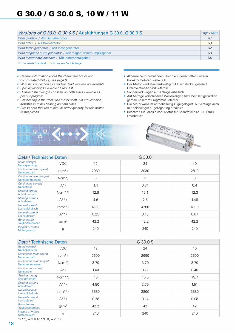
G 30.0 / G 30.0 S, 10 W / 11 W
• General information about the characteristics of our commutated motors, see page 8• With flat connection as standard, lead versions are available • Special windings available on request• Different shaft lengths or shaft on both sides available as per our program• Ball bearing in the front side motor shaft. On request also available with ball bearing on both sides• Please note that the minimum order quantity for this motor is 100 pieces
• Allgemeine Informationen über die Eigenschaften unserer Kollektormotoren siehe S. 8• Der Motor wird standardmäßig mit Flachstecker geliefert. Litzenversionen sind lieferbar• Sonderwicklungen auf Anfrage erhältlich• Auf Anfrage verschiedene Wellenlängen bzw. beidseitige Wellen gemäß unserem Programm lieferbar• Die Motorwelle ist antriebsseitig kugelgelagert. Auf Anfrage auch mit beidseitiger Kugellagerung erhältlich• Beachten Sie, dass dieser Motor für Bedarfsfälle ab 100 Stück lieferbar ist
Versions of G 30.0, G 30.0 S / Ausführungen G 30.0, G 30.0 S Page / Seite
With gearbox / Als Getriebemotor 47With brake / Als Bremsmotor 60With tacho generator / Mit Tachogenerator 62With magnetic pulse generator / Mit magnetischem Impulsgeber 63With incremental encoder / Mit Inkrementalgeber 64n Standard / Standard n On request / auf Anfrage
Data / Technische Daten G 30.0Rated voltage/Nennspannung VDC 12 24 40
Continuous rated speed/Nenndrehzahl rpm*) 2980 3030 2810
Continuous rated torque/Nenndrehmoment Ncm*) 3 3 3
Continuous current/Nennstrom A*) 1.4 0.71 0.4
Starting torque/Anlaufmoment Ncm**) 12.9 12.1 12.3
Starting current/Anlaufstrom A**) 4.6 2.5 1.46
No load speed/Leerlaufdrehzahl rpm**) 4130 4260 4100
No load current/Leerlaufstrom A**) 0.25 0.13 0.07
Rotor inertia/Trägheitsmoment gcm2 42.2 42.2 42.2
Weight of motor/Motorgewicht g 240 240 240
Data / Technische Daten G 30.0 SRated voltage/Nennspannung VDC 12 24 40
Continuous rated speed/Nenndrehzahl rpm*) 2500 2650 2600
Continuous rated torque/Nenndrehmoment Ncm*) 3.70 3.70 3.70
Continuous current/Nennstrom A*) 1.40 0.71 0.40
Starting torque/Anlaufmoment Ncm**) 16 16.5 15.7
Starting current/Anlaufstrom A**) 4.80 2.75 1.51
No load speed/Leerlaufdrehzahl rpm**) 3550 3800 3580
No load current/Leerlaufstrom A**) 0.28 0.14 0.08
Rotor inertia/Trägheitsmoment gcm2 42.2 42 42
Weight of motor/Motorgewicht g 240 240 240
*) DJw = 100 K; **) JR = 20°C

19
G 30.0 / G 30.0 S, 10 W / 11 W
75±05
45°
4 x Ø 2.7+0.1
Ø 16±0.1
Ø 22±0.1
4 x M3; 6.5Depth/Tiefe
9 ±0.5
2+0.5
Ø 12
-0.1
2+0.5
18±0.5
ca. 4.5
+0.3
Ø 30
.6 -0
.2
75 ±0.5
Ø 3
g5
0.12
0.12
Ø 5.
7
Ø 12
-0.1
A
45°
15° +0.05
Ø 1.6
-0.10
Ø 16
Ø 2.
7±0.
1
23.5
Ø 19.25A
Dimensions in mm / Maßzeichnung in mm
-2 0 2 4 6 8 10 12 14 16 18 20Ncm
7000
6000
5000
4000
3000
2000
1000
0
70
60
50
40
30
20
10
0
7
6
5
4
3
2
1
0 rated
spee
d/Dr
ehza
hl n (
rpm)
effic
iency
/Wirk
ungs
grad
η (%
)
curre
nt/S
trom
I (A)
MN
N = f (M)J = f (M)
η
ϑR = 20°C
W= 100K
-2 0 2 4 6 8 10 12 14 16 18 20Ncm
7000
6000
5000
4000
3000
2000
1000
0
70
60
50
40
30
20
10
0
2.8
2.4
2
1.6
1.2
0.8
0.4
0 rated
spee
d/Dr
ehza
hl n (
rpm)
effic
iency
/Wirk
ungs
grad
η (%
)
curre
nt/S
trom
I (A)
MN
N = f (M)
J = f (M)
η
ϑR = 20°C
W= 100K
-2 0 2 4 6 8 10 12 14 16 18 20Ncm
7000
6000
5000
4000
3000
2000
1000
0
70
60
50
40
30
20
10
0
2.8
2.4
2
1.6
1.2
0.8
0.4
0 rated
spee
d/Dr
ehza
hl n (
rpm)
effic
iency
/Wirk
ungs
grad
η (%
)
curre
nt/S
trom
I (A)
MN
N = f (M)J = f (M)
η
ϑR = 20°C
W= 100K
-2 0 2 4 6 8 10 12 14 16 18 20Ncm
7000
6000
5000
4000
3000
2000
1000
0
70
60
50
40
30
20
10
0
7
6
5
4
3
2
1
0 rated
spee
d/Dr
ehza
hl n (
rpm)
effic
iency
/Wirk
ungs
grad
η (%
)
curre
nt/S
trom
I (A)
MN
N = f (M) J = f (M)
η
ϑR = 20°C
-2 0 2 4 6 8 10 12 14 16 18 20Ncm
7000
6000
5000
4000
3000
2000
1000
0
70
60
50
40
30
20
10
0
2.8
2.4
2
1.6
1.2
0.8
0.4
0 rated
spee
d/Dr
ehza
hl n (
rpm)
effic
iency
/Wirk
ungs
grad
η (%
)
curre
nt/S
trom
I (A)
MN
N = f (M) J = f (M)
η
ϑR = 20°C
-2 0 2 4 6 8 10 12 14 16 18 20Ncm
7000
6000
5000
4000
3000
2000
1000
0
70
60
50
40
30
20
10
0
2.8
2.4
2
1.6
1.2
0.8
0.4
0 rated
spee
d/Dr
ehza
hl n (
rpm)
effic
iency
/Wirk
ungs
grad
η (%
)
curre
nt/S
trom
I (A)
MN
N = f (M) J = f (M)η
ϑR = 20°C
Characteristic diagram / Belastungskennlinien In accordance with EN 60034 Belastungskennlinien gezeichnet nach EN 60034
G 30.0, 12V G 30.0 S, 12V
G 30.0, 24V G 30.0 S, 24V
G 30.0, 40V G 30.0 S, 40V
Shaft / Welle front / vorne back / hinten
3 x 18 mm -
3 x 10 mm -
3 x 10 mm 3 x 15 mm
Faxial = max. 4NFradial = max. 8N

20
GR 42x25, 15 W
• General information about the characteristics of our commutated motors, see page 8• The standard version has leads (300 mm)• Special windings available on request• Different shaft lengths or shaft on both sides available as per our program• Protection class IP 50, higher class available on request• Ball bearing in the motor shaft. For projects the motor is also available with slide bearing (G 42)
• Allgemeine Informationen über die Eigenschaften unserer Kollektormotoren siehe S. 8• Der Motor wird standardmäßig mit Litzen (300 mm) geliefert• Sonderwicklungen auf Anfrage erhältlich• Auf Anfrage verschiedene Wellenlängen bzw. beidseitige Wellen gemäß unserem Programm lieferbar• Schutzart IP 50, auf Anfrage auch höher• Die Motorwelle ist kugelgelagert. Projektbezogen ist der Motor auch mit Gleitlager erhältlich (G 42)
Versions of GR 42x25 / Ausführungen GR 42x25 Page / Seite
With gearbox / Als Getriebemotor 47With brake / Als Bremsmotor 60With controller / Mit Regelelektronik 66With tacho generator / Mit Tachogenerator 62With magnetic pulse generator / Mit magnetischem Impulsgeber 63With incremental encoder / Mit Inkrementalgeber 64n Standard / Standard n On request / auf Anfrage
Data / Technische Daten GR 42x25Rated voltage/Nennspannung VDC 12 24 40
Continuous rated speed/Nenndrehzahl rpm*) 3450 3600 3700
Continuous rated torque/Nenndrehmoment Ncm*) 3.9 3.8 3.9
Continuous current/Nennstrom A*) 1.9 0.9 0.6
Starting torque/Anlaufmoment Ncm**) 19 20 22
Starting current/Anlaufstrom A**) 7.8 4 2.76
No load speed/Leerlaufdrehzahl rpm**) 4350 4200 4400
No load current/Leerlaufstrom A**) 0.34 0.17 0.11
Demagnetization current/Entmagnetisierstrom A**) 14 6.5 4.1
Rotor inertia/Trägheitsmoment gcm2 71 71 71
Weight of motor/Motorgewicht g 390 390 390
*) DJw = 100 K; **) JR = 20°C

21
-2 0 2 4 6 8 10 12 14 16 18 20Ncm
7000
6000
5000
4000
3000
2000
1000
0
70
60
50
40
30
20
10
0
14
12
10
8
6
4
2
0 rated
spee
d/Dr
ehza
hl n (
rpm)
effic
iency
/Wirk
ungs
grad
η (%
)
curre
nt/S
trom
I (A)
MN
N = f (M)
J = f (M)
η
ϑR = 20°C
W= 100K
-2 0 2 4 6 8 10 12 14 16 18 20Ncm
7000
6000
5000
4000
3000
2000
1000
0
70
60
50
40
30
20
10
0
2.8
2.4
2
1.8
1.2
0.8
0.4
0 rated
spee
d/Dr
ehza
hl n (
rpm)
effic
iency
/Wirk
ungs
grad
η (%
)
curre
nt/S
trom
I (A)
MN
N = f (M) J = f (M)η
ϑR = 20°C
W= 100K
-4 0 4 8 12 16 20 24 28 32 36 40Ncm
7000
6000
5000
4000
3000
2000
1000
0
70
60
50
40
30
20
10
0
7
6
5
4
3
2
1
0 rated
spee
d/Dr
ehza
hl n (
rpm)
effic
iency
/Wirk
ungs
grad
η (%
)
curre
nt/S
trom
I (A)
MN
N = f (M) J = f (M)
η
ϑR = 20°C
W= 100K
-2 0 2 4 6 8 10 12 14 16 18 20Ncm
7000
6000
5000
4000
3000
2000
1000
0
70
60
50
40
30
20
10
0
7
6
5
4
3
2
1
0 rated
spee
d/Dr
ehza
hl n (
rpm)
effic
iency
/Wirk
ungs
grad
η (%
)
curre
nt/S
trom
I (A)
MN
N = f (M)
J = f (M)
η
ϑR = 20°C
W= 100K
-4 0 4 8 12 16 20 24 28 32 36 40Ncm
7000
6000
5000
4000
3000
2000
1000
0
70
60
50
40
30
20
10
0
14
12
10
8
6
4
2
0 rated
spee
d/Dr
ehza
hl n (
rpm)
effic
iency
/Wirk
ungs
grad
η (%
)
curre
nt/S
trom
I (A)
MN
N = f (M)J = f (M)
η
ϑR = 20°C
W= 100K
-4 0 4 8 12 16 20 24 28 32 36 40Ncm
7000
6000
5000
4000
3000
2000
1000
0
70
60
50
40
30
20
10
0
7
6
5
4
3
2
1
0 rated
spee
d/Dr
ehza
hl n (
rpm)
effic
iency
/Wirk
ungs
grad
η (%
)
curre
nt/S
trom
I (A)
MN
N = f (M)
J = f (M)
η
ϑR = 20°C
W= 100K
-2 0 2 4 6 8 10 12 14 16 18 20Ncm
7000
6000
5000
4000
3000
2000
1000
0
70
60
50
40
30
20
10
0
14
12
10
8
6
4
2
0 rated
spee
d/Dr
ehza
hl n (
rpm)
effic
iency
/Wirk
ungs
grad
η (%
)
curre
nt/S
trom
I (A)
MN
N = f (M)
J = f (M)
η
ϑR = 20°C
W= 100K
-2 0 2 4 6 8 10 12 14 16 18 20Ncm
7000
6000
5000
4000
3000
2000
1000
0
70
60
50
40
30
20
10
0
2.8
2.4
2
1.8
1.2
0.8
0.4
0 rated
spee
d/Dr
ehza
hl n (
rpm)
effic
iency
/Wirk
ungs
grad
η (%
)
curre
nt/S
trom
I (A)
MN
N = f (M) J = f (M)η
ϑR = 20°C
W= 100K
-4 0 4 8 12 16 20 24 28 32 36 40Ncm
7000
6000
5000
4000
3000
2000
1000
0
70
60
50
40
30
20
10
0
7
6
5
4
3
2
1
0 rated
spee
d/Dr
ehza
hl n (
rpm)
effic
iency
/Wirk
ungs
grad
η (%
)
curre
nt/S
trom
I (A)
MN
N = f (M) J = f (M)
η
ϑR = 20°C
W= 100K
-2 0 2 4 6 8 10 12 14 16 18 20Ncm
7000
6000
5000
4000
3000
2000
1000
0
70
60
50
40
30
20
10
0
7
6
5
4
3
2
1
0 rated
spee
d/Dr
ehza
hl n (
rpm)
effic
iency
/Wirk
ungs
grad
η (%
)
curre
nt/S
trom
I (A)
MN
N = f (M)
J = f (M)
η
ϑR = 20°C
W= 100K
-4 0 4 8 12 16 20 24 28 32 36 40Ncm
7000
6000
5000
4000
3000
2000
1000
0
70
60
50
40
30
20
10
0
14
12
10
8
6
4
2
0 rated
spee
d/Dr
ehza
hl n (
rpm)
effic
iency
/Wirk
ungs
grad
η (%
)
curre
nt/S
trom
I (A)
MN
N = f (M)J = f (M)
η
ϑR = 20°C
W= 100K
-4 0 4 8 12 16 20 24 28 32 36 40Ncm
7000
6000
5000
4000
3000
2000
1000
0
70
60
50
40
30
20
10
0
7
6
5
4
3
2
1
0 rated
spee
d/Dr
ehza
hl n (
rpm)
effic
iency
/Wirk
ungs
grad
η (%
)
curre
nt/S
trom
I (A)
MN
N = f (M)
J = f (M)
η
ϑR = 20°C
W= 100K
GR 42x25, 15 W
Dimensions in mm / Maßzeichnung in mm
Characteristic diagram / Belastungskennlinien In accordance with EN 60034 Belastungskennlinien gezeichnet nach EN 60034
GR 42x25, 12V GR 42x25, 24V
GR 42x25, 40V
90° ±1°
45°±
1°
22 -0.05
32 ±0.1
4 mal
0.2
6.5mmDepth/Tiefe
B
2
L
A
Ø 42
±0.3
black/schwarz
-+
7 ±2red/rot
300 ±30
20±1
2
1 ±0.3
Ø 9
Ø 5
g5
0.06
0.03
22 -0.05
32±0.1
27.5°
2.75-0.15
90°
30°
0.2
M3
A
Leads/Litzen AWG 22 Tr 64 UL Style 1569
A
B
70±0.8
Shaft / Welle front / vorne back / hinten
5 x 20 mm -
5 x 45 mm -
5 x 45 mm 5 x 45 mm
Faxial = max. 30NFradial = max. 60N

22
GR 42x40, 20 W
Versions of GR 42x40 / Ausführungen GR 42x40 Page / Seite
With gearbox / Als Getriebemotor 47With brake / Als Bremsmotor 60With controller / Mit Regelelektronik 66With tacho generator / Mit Tachogenerator 62With magnetic pulse generator / Mit magnetischem Impulsgeber 63With incremental encoder / Mit Inkrementalgeber 64n Standard / Standard n On request / auf Anfrage
Data / Technische Daten GR 42x40Rated voltage/Nennspannung VDC 12 24 40
Continuous rated speed/Nenndrehzahl rpm*) 3750 3100 3400
Continuous rated torque/Nenndrehmoment Ncm*) 5.3 5.7 5.7
Continuous current/Nennstrom A*) 2.7 1.2 0.8
Starting torque/Anlaufmoment Ncm**) 32 33 36
Starting current/Anlaufstrom A**) 13.2 5.68 3.97
No load speed/Leerlaufdrehzahl rpm**) 4550 3800 3950
No load current/Leerlaufstrom A**) 0.44 0.18 0.12
Demagnetization current/Entmagnetisierstrom A**) 24 10.5 6.3
Rotor inertia/Trägheitsmoment gcm2 110 110 110
Weight of motor/Motorgewicht g 490 490 490
*) DJw = 100 K; **) JR = 20°C
• General information about the characteristics of our commutated motors, see page 8• The standard version has leads (300 mm)• Special windings available on request• Different shaft lengths or shaft on both sides available as per our program• Protection class IP 50, higher class available on request• Ball bearing in the motor shaft. For projects the motor is also available with slide bearing (G 42)
• Allgemeine Informationen über die Eigenschaften unserer Kollektormotoren siehe S. 8• Der Motor wird standardmäßig mit Litzen (300 mm) geliefert• Sonderwicklungen auf Anfrage erhältlich• Auf Anfrage verschiedene Wellenlängen bzw. beidseitige Wellen gemäß unserem Programm lieferbar• Schutzart IP 50, auf Anfrage auch höher• Die Motorwelle ist kugelgelagert. Projektbezogen ist der Motor auch mit Gleitlager erhältlich (G 42)

23
-2 0 2 4 6 8 10 12 14 16 18 20Ncm
7000
6000
5000
4000
3000
2000
1000
0
70
60
50
40
30
20
10
0
14
12
10
8
6
4
2
0 rated
spee
d/Dr
ehza
hl n (
rpm)
effic
iency
/Wirk
ungs
grad
η (%
)
curre
nt/S
trom
I (A)
MN
N = f (M)
J = f (M)
η
ϑR = 20°C
W= 100K
-2 0 2 4 6 8 10 12 14 16 18 20Ncm
7000
6000
5000
4000
3000
2000
1000
0
70
60
50
40
30
20
10
0
2.8
2.4
2
1.8
1.2
0.8
0.4
0 rated
spee
d/Dr
ehza
hl n (
rpm)
effic
iency
/Wirk
ungs
grad
η (%
)
curre
nt/S
trom
I (A)
MN
N = f (M) J = f (M)η
ϑR = 20°C
W= 100K
-4 0 4 8 12 16 20 24 28 32 36 40Ncm
7000
6000
5000
4000
3000
2000
1000
0
70
60
50
40
30
20
10
0
7
6
5
4
3
2
1
0 rated
spee
d/Dr
ehza
hl n (
rpm)
effic
iency
/Wirk
ungs
grad
η (%
)
curre
nt/S
trom
I (A)
MN
N = f (M) J = f (M)
η
ϑR = 20°C
W= 100K
-2 0 2 4 6 8 10 12 14 16 18 20Ncm
7000
6000
5000
4000
3000
2000
1000
0
70
60
50
40
30
20
10
0
7
6
5
4
3
2
1
0 rated
spee
d/Dr
ehza
hl n (
rpm)
effic
iency
/Wirk
ungs
grad
η (%
)
curre
nt/S
trom
I (A)
MN
N = f (M)
J = f (M)
η
ϑR = 20°C
W= 100K
-4 0 4 8 12 16 20 24 28 32 36 40Ncm
7000
6000
5000
4000
3000
2000
1000
0
70
60
50
40
30
20
10
0
14
12
10
8
6
4
2
0 rated
spee
d/Dr
ehza
hl n (
rpm)
effic
iency
/Wirk
ungs
grad
η (%
)
curre
nt/S
trom
I (A)
MN
N = f (M)J = f (M)
η
ϑR = 20°C
W= 100K
-4 0 4 8 12 16 20 24 28 32 36 40Ncm
7000
6000
5000
4000
3000
2000
1000
0
70
60
50
40
30
20
10
0
7
6
5
4
3
2
1
0 rated
spee
d/Dr
ehza
hl n (
rpm)
effic
iency
/Wirk
ungs
grad
η (%
)
curre
nt/S
trom
I (A)
MN
N = f (M)
J = f (M)
η
ϑR = 20°C
W= 100K
-2 0 2 4 6 8 10 12 14 16 18 20Ncm
7000
6000
5000
4000
3000
2000
1000
0
70
60
50
40
30
20
10
0
14
12
10
8
6
4
2
0 rated
spee
d/Dr
ehza
hl n (
rpm)
effic
iency
/Wirk
ungs
grad
η (%
)
curre
nt/S
trom
I (A)
MN
N = f (M)
J = f (M)
η
ϑR = 20°C
W= 100K
-2 0 2 4 6 8 10 12 14 16 18 20Ncm
7000
6000
5000
4000
3000
2000
1000
0
70
60
50
40
30
20
10
0
2.8
2.4
2
1.8
1.2
0.8
0.4
0 rated
spee
d/Dr
ehza
hl n (
rpm)
effic
iency
/Wirk
ungs
grad
η (%
)
curre
nt/S
trom
I (A)
MN
N = f (M) J = f (M)η
ϑR = 20°C
W= 100K
-4 0 4 8 12 16 20 24 28 32 36 40Ncm
7000
6000
5000
4000
3000
2000
1000
0
70
60
50
40
30
20
10
0
7
6
5
4
3
2
1
0 rated
spee
d/Dr
ehza
hl n (
rpm)
effic
iency
/Wirk
ungs
grad
η (%
)
curre
nt/S
trom
I (A)
MN
N = f (M) J = f (M)
η
ϑR = 20°C
W= 100K
-2 0 2 4 6 8 10 12 14 16 18 20Ncm
7000
6000
5000
4000
3000
2000
1000
0
70
60
50
40
30
20
10
0
7
6
5
4
3
2
1
0 rated
spee
d/Dr
ehza
hl n (
rpm)
effic
iency
/Wirk
ungs
grad
η (%
)
curre
nt/S
trom
I (A)
MN
N = f (M)
J = f (M)
η
ϑR = 20°C
W= 100K
-4 0 4 8 12 16 20 24 28 32 36 40Ncm
7000
6000
5000
4000
3000
2000
1000
0
70
60
50
40
30
20
10
0
14
12
10
8
6
4
2
0 rated
spee
d/Dr
ehza
hl n (
rpm)
effic
iency
/Wirk
ungs
grad
η (%
)
curre
nt/S
trom
I (A)
MN
N = f (M)J = f (M)
η
ϑR = 20°C
W= 100K
-4 0 4 8 12 16 20 24 28 32 36 40Ncm
7000
6000
5000
4000
3000
2000
1000
0
70
60
50
40
30
20
10
0
7
6
5
4
3
2
1
0 rated
spee
d/Dr
ehza
hl n (
rpm)
effic
iency
/Wirk
ungs
grad
η (%
)
curre
nt/S
trom
I (A)
MN
N = f (M)
J = f (M)
η
ϑR = 20°C
W= 100K
GR 42x40, 20 W
Dimensions in mm / Maßzeichnung in mm
Characteristic diagram / Belastungskennlinien In accordance with EN 60034 Belastungskennlinien gezeichnet nach EN 60034
GR 42x40, 12V GR 42x40, 24V
GR 42x40, 40V
90° ±1°
45°±
1°
22 -0.05
32 ±0.1
4 mal
0.2
6.5mmDepth/Tiefe
B
2
L
A
Ø 42
±0.3
black/schwarz
-+
7 ±2red/rot
300 ±30
20±1
2
1 ±0.3
Ø 9
Ø 5
g5
0.06
0.03
22 -0.05
32±0.1
27.5°
2.75-0.15
90°
30°
0.2
M3
A
Leads/Litzen AWG 22 Tr 64 UL Style 1569
A
B
85±0.8
Shaft / Welle front / vorne back / hinten
5 x 20 mm -
5 x 45 mm -
5 x 45 mm 5 x 45 mm
Faxial = max. 30NFradial = max. 60N

24
GR 51x30, 40 W
• General information about the characteristics of our commutated motors, see page 8• The standard version has leads (300 mm)• Special and high voltage windings available on request• On request different shaft lengths and diameters or shaft on both sides are available as per our program• Protection class IP 40• Motor shaft with ball bearing• Please note that the minimum order quantity for the motor is 500 pieces
• Allgemeine Informationen über die Eigenschaften unserer Kollektormotoren siehe S. 8• Sonder- und Hochspannungswicklungen auf Anfrage erhältlich• Der Motor wird standardmäßig mit Litzen (300 mm) geliefert• Auf Anfrage verschiedene Wellenlängen und -durchmesser bzw. beidseitige Wellen gemäß unserem Programm lieferbar• Schutzart IP 40• Die Motorwelle ist kugelgelagert• Beachten Sie, dass dieser Motor für Bedarfsfälle ab 500 Stück lieferbar ist
Versions of GR 51x30 / Ausführungen GR 51x30 Page / Seite
With gearbox / Als Getriebemotor 47With brake / Als Bremsmotor 60With controller / Mit Regelelektronik 66With tacho generator / Mit Tachogenerator 62With magnetic pulse generator / Mit magnetischem Impulsgeber 63With incremental encoder / Mit Inkrementalgeber 64n Standard / Standard n On request / auf Anfrage
Data / Technische Daten GR 51x30Rated voltage/Nennspannung VDC 12 24 40 60
Continuous rated speed/Nenndrehzahl rpm*) 3790 3600 3680 4000
Continuous rated torque/Nenndrehmoment Ncm*) 9 10 10 10
Continuous current/Nennstrom A*) 4.5 2.3 1.3 0.9
Starting torque/Anlaufmoment Ncm**) 57 67 66 69
Starting current/Anlaufstrom A**) 23.7 13.5 7.7 5.6
No load speed/Leerlaufdrehzahl rpm**) 4490 4200 4280 4500
No load current/Leerlaufstrom A**) 1.16 0.56 0.34 0.24
Demagnetization current/Entmagnetisierstrom A**) 42 20 12 8.5
Rotor inertia/Trägheitsmoment gcm2 230 230 230 230
Weight of motor/Motorgewicht g 650 650 650 650
*) DJw = 100 K; **) JR = 20°C

25
GR 51x30, 40 W
-10 0 10 20 30 40 50 60 70 80 90 100Ncm
7000
6000
5000
4000
3000
2000
1000
0
70
60
50
40
30
20
10
0
28
24
20
16
12
8
4
0 rated
spee
d/Dr
ehza
hl n (
rpm)
effic
iency
/Wirk
ungs
grad
η (%
)
curre
nt/S
trom
I (A)
MN
N = f (M) J = f (M)
η
ϑR = 20°C
W= 100K
-10 0 10 20 30 40 50 60 70 80 90 100Ncm
7000
6000
5000
4000
3000
2000
1000
0
70
60
50
40
30
20
10
0
14
12
10
8
6
4
2
0 rated
spee
d/Dr
ehza
hl n (
rpm)
effic
iency
/Wirk
ungs
grad
η (%
)
curre
nt/S
trom
I (A)
MN
N = f (M)J = f (M)
η
ϑR = 20°C
W= 100K
-10 0 10 20 30 40 50 60 70 80 90 100Ncm
7000
6000
5000
4000
3000
2000
1000
0
70
60
50
40
30
20
10
0
7
6
5
4
3
2
1
0 rated
spee
d/Dr
ehza
hl n (
rpm)
effic
iency
/Wirk
ungs
grad
η (%
)
curre
nt/S
trom
I (A)
MN
N = f (M)
J = f (M)η
ϑR = 20°C
W= 100K
-10 0 10 20 30 40 50 60 70 80 90 100Ncm
7000
6000
5000
4000
3000
2000
1000
0
70
60
50
40
30
20
10
0
14
12
10
8
6
4
2
0 rated
spee
d/Dr
ehza
hl n (
rpm)
effic
iency
/Wirk
ungs
grad
η (%
)
curre
nt/S
trom
I (A)
MN
N = f (M)J = f (M)
η
ϑR = 20°C
W= 100K
Characteristic diagram / Belastungskennlinien In accordance with EN 60034 Belastungskennlinien gezeichnet nach EN 60034
GR 51x30, 12V GR 51x30, 24V
GR 51x30, 40V GR 51x30, 60V
Dimensions in mm / Maßzeichnung in mm
4xØ3.4
4xØ3.4
Ø36±0.1
Ø40±0.1
Ø25-0.040,06
0,2
0,2
45°90°±1°
95±0.8
2.5 2.5
3.8
Ø51±
0.3
Ø470,15 20±0.5
ØØ 6
g5
0,03
7±2 verzinnt
ze / leads AW G18 UL Style1569 CSA TR 64
45°
22,5°
300±30
RD BK
B
B
0,2
0,24xØ3,4
2xØ2,7
Ø36±0,1
Ø32±0,1
Ø25Ø2 -0.04
weichA
B
A
A
C
95±0.8
Shaft / Welle front / vorne back / hinten
6 x 20 mm -
6 x 45 mm 6 x 46 mm
26
GR 51x58, 60 W
• General information about the characteristics of our commutated motors, see page 8• The standard version has leads (300 mm)• Special and high voltage windings available on request• On request different shaft lengths and diameters or shaft on both sides are available as per our program• Protection class IP 40• Motor shaft with ball bearing• Please note that the minimum order quantity for the motor is 500 pieces
• Allgemeine Informationen über die Eigenschaften unserer Kollektormotoren siehe S. 8• Sonder- und Hochspannungswicklungen auf Anfrage erhältlich• Der Motor wird standardmäßig mit Litzen (300 mm) geliefert• Auf Anfrage verschiedene Wellenlängen und -durchmesser bzw. beidseitige Wellen gemäß unserem Programm lieferbar• Schutzart IP 40• Die Motorwelle ist kugelgelagert• Beachten Sie, dass dieser Motor für Bedarfsfälle ab 500 Stück lieferbar ist
Versions of GR 51x58 / Ausführungen GR 51x58 Page / Seite
With gearbox / Als Getriebemotor 47With brake / Als Bremsmotor 60With controller / Mit Regelelektronik 66With tacho generator / Mit Tachogenerator 62With magnetic pulse generator / Mit magnetischem Impulsgeber 63With incremental encoder / Mit Inkrementalgeber 64n Standard / Standard n On request / auf Anfrage
Data / Technische Daten GR 51x58Rated voltage/Nennspannung VDC 12 24 40 60
Continuous rated speed/Nenndrehzahl rpm*) 3000 3000 3300 3450
Continuous rated torque/Nenndrehmoment Ncm*) 15.5 17 17 17
Continuous current/Nennstrom A*) 5.5 2.9 1.9 1.3
Starting torque/Anlaufmoment Ncm**) 114 143 139 144
Starting current/Anlaufstrom A**) 35.3 22.8 14.4 10.3
No load speed/Leerlaufdrehzahl rpm**) 3200 3250 3450 3600
No load current/Leerlaufstrom A**) 0.8 0.4 0.27 0.2
Demagnetization current/Entmagnetisierstrom A**) 61 31 20 13.5
Rotor inertia/Trägheitsmoment gcm2 460 460 460 460
Weight of motor/Motorgewicht g 1000 1000 1000 1000
*) DJw = 100 K; **) JR = 20°C

27
GR 51x58, 60 W
-20 0 20 40 60 80 100 120 140 160 180 200Ncm
7000
6000
5000
4000
3000
2000
1000
0
100
80
60
40
20
0
56
48
40
32
24
16
8
0 rated
spee
d/Dr
ehza
hl n (
rpm)
effic
iency
/Wirk
ungs
grad
η (%
)
curre
nt/S
trom
I (A)
MN
N = f (M)
J = f (M)
η
ϑR = 20°C
W= 100K
-20 0 20 40 60 80 100 120 140 160 180 200Ncm
7000
6000
5000
4000
3000
2000
1000
0
100
80
60
40
20
0
28
24
20
16
12
8
4
0 rated
spee
d/Dr
ehza
hl n (
rpm)
effic
iency
/Wirk
ungs
grad
η (%
)
curre
nt/S
trom
I (A)
MN
N = f (M)J = f (M)
η
ϑR = 20°C
W= 100K
-20 0 20 40 60 80 100 120 140 160 180 200Ncm
7000
6000
5000
4000
3000
2000
1000
0
100
80
60
40
20
0
14
12
10
8
6
4
2
0 rated
spee
d/Dr
ehza
hl n (
rpm)
effic
iency
/Wirk
ungs
grad
η (%
)
curre
nt/S
trom
I (A)
MN
N = f (M) J = f (M)
η
ϑR = 20°C
W= 100K
-20 0 20 40 60 80 100 120 140 160 180 200Ncm
7000
6000
5000
4000
3000
2000
1000
0
100
80
60
40
20
0
28
24
20
16
12
8
4
0 rated
spee
d/Dr
ehza
hl n (
rpm)
effic
iency
/Wirk
ungs
grad
η (%
)
curre
nt/S
trom
I (A)
MN
N = f (M)J = f (M)
η
ϑR = 20°C
W= 100K
Characteristic diagram / Belastungskennlinien In accordance with EN 60034 Belastungskennlinien gezeichnet nach EN 60034
GR 51x58, 12V GR 51x58, 24V
GR 51x58, 40V GR 51x58, 60V
Dimensions in mm / Maßzeichnung in mm
4xØ3.4
4xØ3.4
Ø36±0.1
Ø40±0.1
Ø25-0.040,06
0,2
0,2
45°90°±1°
95±0.8
2.5 2.5
3.8
Ø51±
0.3
Ø470,15 20±0.5
ØØ 6
g5
0,03
7±2 verzinnt
ze / leads AW G18 UL Style1569 CSA TR 64
45°
22,5°
300±30
RD BK
B
B
0,2
0,24xØ3,4
2xØ2,7
Ø36±0,1
Ø32±0,1
Ø25Ø2 -0.04
weichA
B
A
A
C
125±0.8
Shaft / Welle front / vorne back / hinten
6 x 20 mm -
6 x 45 mm 6 x 54.5 mm

28
GR 53x30, 40 W
• General information about the characteristics of our commutated motors, see page 8• The standard version has leads (300 mm)• Special and high voltage windings available on request• On request different shaft lengths and diameters or shaft on both sides are available as per our program• Protection class IP 50, higher class available on request• Motor shaft with ball bearing
• Allgemeine Informationen über die Eigenschaften unserer Kollektormotoren siehe S. 8• Der Motor wird standardmäßig mit Litzen (300 mm) geliefert• Sonder- und Hochspannungswicklungen auf Anfrage erhältlich• Auf Anfrage verschiedene Wellenlängen und -durchmesser bzw. beidseitige Wellen gemäß unserem Programm lieferbar• Schutzart IP 50, auf Anfrage auch höher• Die Motorwelle ist kugelgelagert
Versions of GR 53x30 / Ausführungen GR 53x30 Page / Seite
With gearbox / Als Getriebemotor 47With brake / Als Bremsmotor 60With controller / Mit Regelelektronik 66With tacho generator / Mit Tachogenerator 62With magnetic pulse generator / Mit magnetischem Impulsgeber 63With incremental encoder / Mit Inkrementalgeber 64n Standard / Standard n On request / auf Anfrage
Data / Technische Daten GR 53x30Rated voltage/Nennspannung VDC 12 24 40 60
Continuous rated speed/Nenndrehzahl rpm*) 3790 3600 3680 4000
Continuous rated torque/Nenndrehmoment Ncm*) 9 10 10 10
Continuous current/Nennstrom A*) 4.5 2.3 1.3 0.9
Starting torque/Anlaufmoment Ncm**) 57 67 66 69
Starting current/Anlaufstrom A**) 23.7 13.5 7.7 5.6
No load speed/Leerlaufdrehzahl rpm**) 4490 4200 4280 4500
No load current/Leerlaufstrom A**) 0.58 0.28 0.17 0.12
Demagnetization current/Entmagnetisierstrom A**) 42 20 12 8.5
Rotor inertia/Trägheitsmoment gcm2 230 230 230 230
Weight of motor/Motorgewicht g 850 850 850 850
*) DJw = 100 K; **) JR = 20°C

29
95±0.8
90°±1°
M4
36 ±0.1
025 -0.04
4xM4 0.2 A
B
2.5
2.5
95±0.8
Ø 10
A
20±1
2.8±0.2
0.06
0.04
AMeßdruck 1.5N
Ø 6
g5
Ø 52
±0.3
Lead/Litze AWG 18 UL Style 1569 CSA TR 64
- black/schwarz
+ red/rot
7±2
300±30
36±0.1
32±0.10.2
0.2
B
B
2.8-0.1
90°
45°
M4 45°
22.5°
025 -0.04
4xM4 Depth/Tiefe 7mm
-10 0 10 20 30 40 50 60 70 80 90 100Ncm
7000
6000
5000
4000
3000
2000
1000
0
70
60
50
40
30
20
10
0
28
24
20
16
12
8
4
0 rated
spee
d/Dr
ehza
hl n (
rpm)
effic
iency
/Wirk
ungs
grad
η (%
)
curre
nt/S
trom
I (A)
MN
N = f (M) J = f (M)
η
ϑR = 20°C
W= 100K
-10 0 10 20 30 40 50 60 70 80 90 100Ncm
7000
6000
5000
4000
3000
2000
1000
0
70
60
50
40
30
20
10
0
14
12
10
8
6
4
2
0 rated
spee
d/Dr
ehza
hl n (
rpm)
effic
iency
/Wirk
ungs
grad
η (%
)
curre
nt/S
trom
I (A)
MN
N = f (M)J = f (M)
η
ϑR = 20°C
W= 100K
-10 0 10 20 30 40 50 60 70 80 90 100Ncm
7000
6000
5000
4000
3000
2000
1000
0
70
60
50
40
30
20
10
0
7
6
5
4
3
2
1
0 rated
spee
d/Dr
ehza
hl n (
rpm)
effic
iency
/Wirk
ungs
grad
η (%
)
curre
nt/S
trom
I (A)
MN
N = f (M)
J = f (M)η
ϑR = 20°C
W= 100K
-10 0 10 20 30 40 50 60 70 80 90 100Ncm
7000
6000
5000
4000
3000
2000
1000
0
70
60
50
40
30
20
10
0
14
12
10
8
6
4
2
0 rated
spee
d/Dr
ehza
hl n (
rpm)
effic
iency
/Wirk
ungs
grad
η (%
)
curre
nt/S
trom
I (A)
MN
N = f (M)J = f (M)
η
ϑR = 20°C
W= 100K
Dimensions in mm / Maßzeichnung in mm
Characteristic diagram / Belastungskennlinien In accordance with EN 60034 Belastungskennlinien gezeichnet nach EN 60034
GR 53x30, 12V GR 53x30, 24V
GR 53x30, 40 W
Shaft / Welle front / vorne back / hinten
6 x 20 mm -
6 x 45 mm 6 x 54.5 mm
GR 53x30, 40V GR 53x30, 60V
Faxial = max. 130NFradial = max. 90N
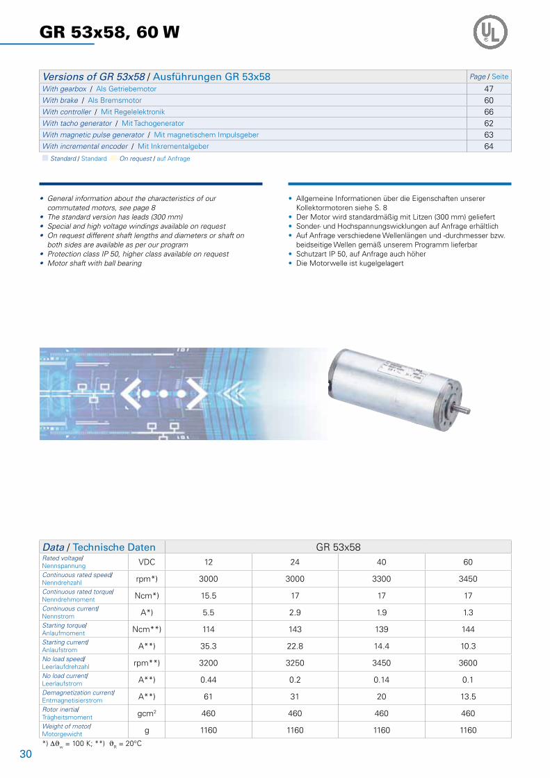
30
GR 53x58, 60 W
• General information about the characteristics of our commutated motors, see page 8• The standard version has leads (300 mm)• Special and high voltage windings available on request• On request different shaft lengths and diameters or shaft on both sides are available as per our program• Protection class IP 50, higher class available on request• Motor shaft with ball bearing
• Allgemeine Informationen über die Eigenschaften unserer Kollektormotoren siehe S. 8• Der Motor wird standardmäßig mit Litzen (300 mm) geliefert• Sonder- und Hochspannungswicklungen auf Anfrage erhältlich• Auf Anfrage verschiedene Wellenlängen und -durchmesser bzw. beidseitige Wellen gemäß unserem Programm lieferbar• Schutzart IP 50, auf Anfrage auch höher• Die Motorwelle ist kugelgelagert
Versions of GR 53x58 / Ausführungen GR 53x58 Page / Seite
With gearbox / Als Getriebemotor 47With brake / Als Bremsmotor 60With controller / Mit Regelelektronik 66With tacho generator / Mit Tachogenerator 62With magnetic pulse generator / Mit magnetischem Impulsgeber 63With incremental encoder / Mit Inkrementalgeber 64n Standard / Standard n On request / auf Anfrage
Data / Technische Daten GR 53x58Rated voltage/Nennspannung VDC 12 24 40 60
Continuous rated speed/Nenndrehzahl rpm*) 3000 3000 3300 3450
Continuous rated torque/Nenndrehmoment Ncm*) 15.5 17 17 17
Continuous current/Nennstrom A*) 5.5 2.9 1.9 1.3
Starting torque/Anlaufmoment Ncm**) 114 143 139 144
Starting current/Anlaufstrom A**) 35.3 22.8 14.4 10.3
No load speed/Leerlaufdrehzahl rpm**) 3200 3250 3450 3600
No load current/Leerlaufstrom A**) 0.44 0.2 0.14 0.1
Demagnetization current/Entmagnetisierstrom A**) 61 31 20 13.5
Rotor inertia/Trägheitsmoment gcm2 460 460 460 460
Weight of motor/Motorgewicht g 1160 1160 1160 1160
*) DJw = 100 K; **) JR = 20°C
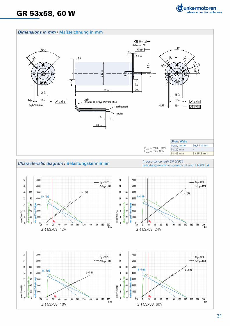
31
GR 53x58, 60 W
125±0.8
M4
90°±1°
36 ±0.1
025 -0.04
4xM4 0.2 A
B
2.5
2.5
125 ±0.8
A
20 ±1
2.8 ±0.2
0.06
0.04
AMeßdruck 1.5N
Ø 6
g5
Lead/Litze AWG 18 UL Style 1569 CSA TR 64
- black/schwarz
+ red/rot7±2
300 ±30
36±0.1
32±0.10.2
0.2
B
B
2.8 -0.1
90°
45°
M4
45°22.5°
025 -0.04
4xM4 Depth/Tiefe 7mm Ø
52 ±0
.3
Ø 10
-20 0 20 40 60 80 100 120 140 160 180 200Ncm
7000
6000
5000
4000
3000
2000
1000
0
100
80
60
40
20
0
56
48
40
32
24
16
8
0 rated
spee
d/Dr
ehza
hl n (
rpm)
effic
iency
/Wirk
ungs
grad
η (%
)
curre
nt/S
trom
I (A)
MN
N = f (M)
J = f (M)
η
ϑR = 20°C
W= 100K
-20 0 20 40 60 80 100 120 140 160 180 200Ncm
7000
6000
5000
4000
3000
2000
1000
0
100
80
60
40
20
0
28
24
20
16
12
8
4
0 rated
spee
d/Dr
ehza
hl n (
rpm)
effic
iency
/Wirk
ungs
grad
η (%
)
curre
nt/S
trom
I (A)
MN
N = f (M)J = f (M)
η
ϑR = 20°C
W= 100K
-20 0 20 40 60 80 100 120 140 160 180 200Ncm
7000
6000
5000
4000
3000
2000
1000
0
100
80
60
40
20
0
14
12
10
8
6
4
2
0 rated
spee
d/Dr
ehza
hl n (
rpm)
effic
iency
/Wirk
ungs
grad
η (%
)
curre
nt/S
trom
I (A)
MN
N = f (M) J = f (M)
η
ϑR = 20°C
W= 100K
-20 0 20 40 60 80 100 120 140 160 180 200Ncm
7000
6000
5000
4000
3000
2000
1000
0
100
80
60
40
20
0
28
24
20
16
12
8
4
0 rated
spee
d/Dr
ehza
hl n (
rpm)
effic
iency
/Wirk
ungs
grad
η (%
)
curre
nt/S
trom
I (A)
MN
N = f (M)J = f (M)
η
ϑR = 20°C
W= 100K
Dimensions in mm / Maßzeichnung in mm
Characteristic diagram / Belastungskennlinien In accordance with EN 60034 Belastungskennlinien gezeichnet nach EN 60034
GR 53x58, 12V GR 53x58, 24V
GR 53x58, 40V GR 53x58, 60V
Shaft / Welle front / vorne back / hinten
6 x 20 mm -
6 x 45 mm 6 x 54.5 mm
Faxial = max. 130NFradial = max. 90N

32
GR 53 SI, 40 - 60 W
• General information about the characteristics of our commutated motors, see page 8• With integral speed controller (digital) for 4-quadrant drive and integral magnetic encoder• As standard, the target speed can be set using a 0...+10V analog voltage input• There are two digital inputs for selecting the four operating conditions: rotation clockwise/ counter-clockwise, controller block, and stop with holding torque• In addition, there are digital outputs, which provide a pulsed output with 16 impulses per revolution and an error signal. A direction of rotation signal (e.g. for monitoring position and speed) is available on request• Two fixed speeds, and acceleration and deacceleration ramps can be stored in memory• The motor is supplied as standard with a 12-pin connector• On request different shaft lenghts available• Protection class IP 54, IP 65 available on request• Motor shaft with ball bearing• For further technical data and information on terminal assignment, please see the operating manual at www.dunkermotoren.com (downloads)
Versions of GR 53 SI / Ausführungen GR 53 SI Page / Seite
With gearbox / Als Getriebemotor 474Q controller attached / Mit angebauter 4Q-Steuerungselektronik 32n Standard / Standard n On request / auf Anfrage
Data / Technische Daten GR 53x30 SI GR 53x58 SIRated voltage/Nennspannung VDC 12 24 12 24 40
Continuous rated speed/Nenndrehzahl rpm*) 3790 3600 3000 3300 3000
Continuous rated torque/Nenndrehmoment Ncm*) 9 10 15.5 17 17
Continuous current/Nennstrom A*) 4.5 2.3 5.5 2.9 1.9
Starting torque/Anlaufmoment Ncm**) 57 67 114***) 143***) 139
Starting current/Anlaufstrom A**) 23.7 13.5 35.3***) 22.8***) 14.4
Electronic peak current/Zul. Spitzenstrom der Elektronik A**) 25 15 25 15 15
Rotor inertia/Trägheitsmoment gcm2 230 230 460 460 460
Weight of motor/Motorgewicht g 1050 1050 1360 1360 1360
Voltage range/Max. zul. Spannungsbereich VDC 12 ... 40 12 ... 40 12 ... 40 12 ... 40 12 ... 40
Recommended speed control range/Empfohlener Drehzahlregelbereich rpm 50 ... Rated speed / Nenndrehzahl
*) DJw = 100 K; **) JR = 20°C; ***) Will be restricted by peak current of the electronic / Wird durch den Spitzenstrom der Elektronik eingegrenzt
• Allgemeine Informationen über die Eigenschaften unserer Kollektormotoren siehe S. 8• Mit integriertem Speedcontroller (digital) für 4-Quadrantenbetrieb und integriertem magnetischen Impulsgeber• Die Drehzahlsollwertvorgabe erfolgt standardmäßig über einen Analogspannungseingang 0...+10V• Über zwei digitale Eingänge lassen sich die vier Betriebszustände Drehrichtung rechts, Drehrichtung links, Reglersperre und Stopp mit Haltemoment anwählen • Zusätzlich werden digitale Ausgänge herausgeführt, womit ein Pulsausgang mit 16 Impulsen pro Umdrehung und ein Störungssignal zur Verfügung stehen. Optional kann ein Drehrichtungssignal zur Verfügung gestellt werden• Das Abspeichern von 2 festen Geschwindigkeiten sowie von Beschleunigungs- und Bremsrampe ist möglich• Der Motor wird standardmäßig mit einem 12-poligen Stecker geliefert• Auf Anfrage verschiedene Wellenlängen lieferbar• Schutzart IP 54, optional IP 65• Die Motorwelle ist kugelgelagert• Weitere technische Daten sowie Informationen zur Anschlussbelegung finden Sie in der Betriebsanleitung unter www.dunkermotoren.de (downloads)
SPEED CONTROLLER
ATTACHED
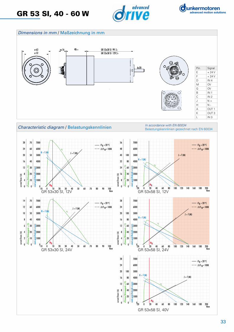
33
GR 53 SI, 40 - 60 W
ca.16ø 52
6x20
ø 63 48±0.5 GR 53x30 SI 99.5±1
GR 53x58 SI 129.5±1
Dimensions in mm / Maßzeichnung in mm
-10 0 10 20 30 40 50 60 70 80 90 100Ncm
7000
6000
5000
4000
3000
2000
1000
0
70
60
50
40
30
20
10
0
28
24
20
16
12
8
4
0 rated
spee
d/Dr
ehza
hl n (
rpm)
effic
iency
/Wirk
ungs
grad
η (%
)
curre
nt/S
trom
I (A)
MN
N = f (M) J = f (M)
η
ϑR = 20°C
W= 100K
-10 0 10 20 30 40 50 60 70 80 90 100Ncm
7000
6000
5000
4000
3000
2000
1000
0
70
60
50
40
30
20
10
0
14
12
10
8
6
4
2
0 rated
spee
d/Dr
ehza
hl n (
rpm)
effic
iency
/Wirk
ungs
grad
η (%
)
curre
nt/S
trom
I (A)
MN
N = f (M)J = f (M)
η
ϑR = 20°C
W= 100K
-20 0 20 40 60 80 100 120 140 160 180 200Ncm
7000
6000
5000
4000
3000
2000
1000
0
100
80
60
40
20
0
56
48
40
32
24
16
8
0 rated
spee
d/Dr
ehza
hl n (
rpm)
effic
iency
/Wirk
ungs
grad
η (%
)
curre
nt/S
trom
I (A)
MN
N = f (M)
J = f (M)
η
ϑR = 20°C
W= 100K
-20 0 20 40 60 80 100 120 140 160 180 200Ncm
7000
6000
5000
4000
3000
2000
1000
0
100
80
60
40
20
0
28
24
20
16
12
8
4
0 rated
spee
d/Dr
ehza
hl n (
rpm)
effic
iency
/Wirk
ungs
grad
η (%
)
curre
nt/S
trom
I (A)
MN
N = f (M)J = f (M)
η
ϑR = 20°C
W= 100K
-20 0 20 40 60 80 100 120 140 160 180 200Ncm
7000
6000
5000
4000
3000
2000
1000
0
100
80
60
40
20
0
28
24
20
16
12
8
4
0 rated
spee
d/Dr
ehza
hl n (
rpm)
effic
iency
/Wirk
ungs
grad
η (%
)
curre
nt/S
trom
I (A)
MN
N = f (M)J = f (M)
η
ϑR = 20°C
W= 100K
Characteristic diagram / Belastungskennlinien In accordance with EN 60034 Belastungskennlinien gezeichnet nach EN 60034
GR 53x30 SI, 12V GR 53x58 SI, 12V
GR 53x30 SI, 24V GR 53x58 SI, 24V
GR 53x58 SI, 40V
Pin Signal
E + 24 V
F + 24 V
D IN 4
M OV
G OV
B IN 1
C IN 2
J N +
H N -
A OUT 1
K OUT 3
L IN 3

34
GR 63x25, 50 W
• General information about the characteristics of our commutated motors, see page 8• The standard version has leads (300 mm)• Special and high voltage windings available on request • On request different shaft lengths and diameters or shaft on both sides are available as per our program• Protection class IP 50, higher class available on request• Motor shaft with ball bearing
• Allgemeine Informationen über die Eigenschaften unserer Kollektormotoren siehe S. 8• Der Motor wird standardmäßig mit Litzen (300 mm) geliefert• Sonder- und Hochspannungswicklungen auf Anfrage erhältlich• Auf Anfrage verschiedene Wellenlängen und -durchmesser bzw. beidseitige Wellen gemäß unserem Programm lieferbar• Schutzart IP 50, auf Anfrage auch höher• Die Motorwelle ist kugelgelagert
Versions of GR 63x25 / Ausführungen GR 63x25 Page / Seite
With gearbox / Als Getriebemotor 47With brake / Als Bremsmotor 60With controller / Mit Regelelektronik 66With tacho generator / Mit Tachogenerator 62With magnetic pulse generator / Mit magnetischem Impulsgeber 63With incremental encoder / Mit Inkrementalgeber 64n Standard / Standard n On request / auf Anfrage
Data / Technische Daten GR 63x25Rated voltage/Nennspannung VDC 12 24 40 60
Continuous rated speed/Nenndrehzahl rpm*) 3100 3300 3500 3300
Continuous rated torque/Nenndrehmoment Ncm*) 13.7 14 13.3 14.5
Continuous current/Nennstrom A*) 5.2 2.7 1.7 1.1
Starting torque/Anlaufmoment Ncm**) 82 108 118 116
Starting current/Anlaufstrom A**) 27 18 12 7.6
No load speed/Leerlaufdrehzahl rpm**) 3600 3600 3800 3600
No load current/Leerlaufstrom A**) 0.6 0.36 0.21 0.14
Demagnetization current/Entmagnetisierstrom A**) 50 24 16 9.5
Rotor inertia/Trägheitsmoment gcm2 400 400 400 400
Weight of motor/Motorgewicht g 1200 1200 1200 1200
*) DJw = 100 K; **) JR = 20°C
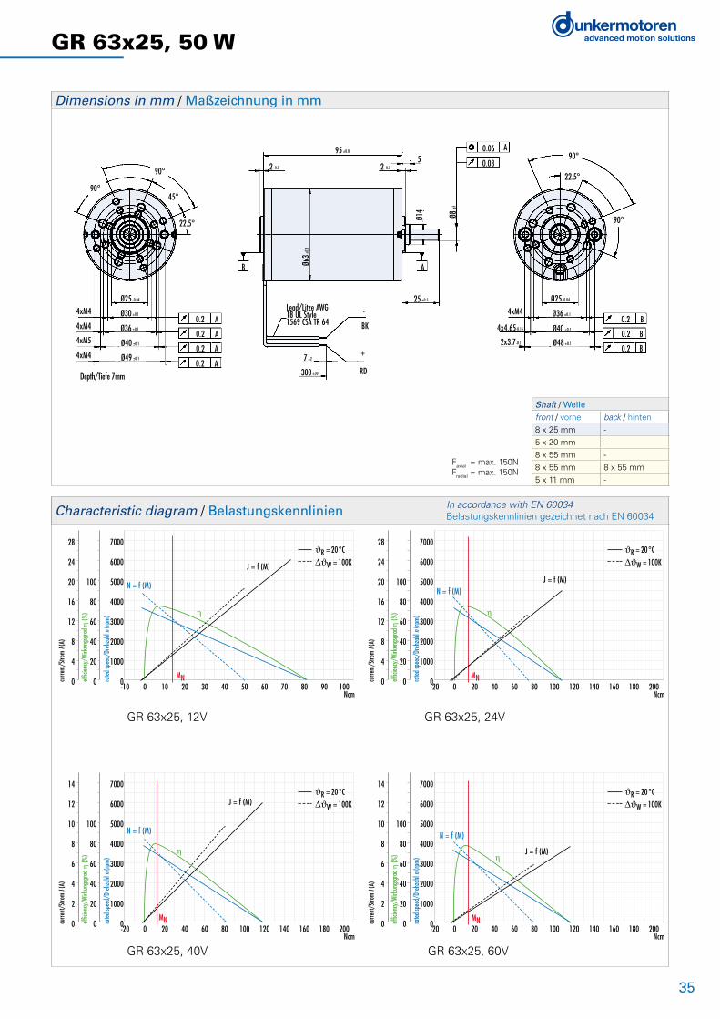
35
GR 63x25, 50 W
95±0.8
90°
90°45°
22.5°
4xM4
4xM4
4xM5
4xM4
Ø25 -0.04
Ø30 ±0.1
Ø40 ±0.1
Ø36 ±0.1
Ø49 ±0.1
0.2
0.2
0.2
0.2
A
A
A
A
Depth/Tiefe 7mm
B AØ63±
0.3
2 -0.3
95 ±0.8
5
25 ±0.5
Ø14
Ø8 g5
2 -0.3
-
BK
+
RD
7 ±2
300 ±30
Lead/Litze AWG18 UL Style1569 CSA TR 64
0.06
0.03
A90°
90°
22.5°
Ø36 ±0.1
Ø40 ±0.1
Ø48 ±0.1
Ø25 -0.04
4xM4
4x4.65-0.15
2x3.7-0.11
0.2
0.2
0.2 B
B
B
-10 0 10 20 30 40 50 60 70 80 90 100Ncm
7000
6000
5000
4000
3000
2000
1000
0
100
80
60
40
20
0
28
24
20
16
12
8
4
0 rated
spee
d/Dr
ehza
hl n (
rpm)
effic
iency
/Wirk
ungs
grad
η (%
)
curre
nt/S
trom
I (A)
MN
N = f (M)
J = f (M)
η
ϑR = 20°C
W = 100K
-20 0 20 40 60 80 100 120 140 160 180 200Ncm
7000
6000
5000
4000
3000
2000
1000
0
100
80
60
40
20
0
14
12
10
8
6
4
2
0 rated
spee
d/Dr
ehza
hl n (
rpm)
effic
iency
/Wirk
ungs
grad
η (%
)
curre
nt/S
trom
I (A)
MN
N = f (M)
J = f (M)
η
ϑR = 20°C
W = 100K
-20 0 20 40 60 80 100 120 140 160 180 200Ncm
7000
6000
5000
4000
3000
2000
1000
0
100
80
60
40
20
0
14
12
10
8
6
4
2
0 rated
spee
d/Dr
ehza
hl n (
rpm)
effic
iency
/Wirk
ungs
grad
η (%
)
curre
nt/S
trom
I (A)
MN
N = f (M)
J = f (M)η
ϑR = 20°C
W = 100K
-20 0 20 40 60 80 100 120 140 160 180 200Ncm
7000
6000
5000
4000
3000
2000
1000
0
100
80
60
40
20
0
28
24
20
16
12
8
4
0 rated
spee
d/Dr
ehza
hl n (
rpm)
effic
iency
/Wirk
ungs
grad
η (%
)
curre
nt/S
trom
I (A)
MN
N = f (M)J = f (M)
η
ϑR = 20°C
W = 100K
Dimensions in mm / Maßzeichnung in mm
Characteristic diagram / Belastungskennlinien In accordance with EN 60034 Belastungskennlinien gezeichnet nach EN 60034
GR 63x25, 12V GR 63x25, 24V
GR 63x25, 40V GR 63x25, 60V
Shaft / Welle front / vorne back / hinten
8 x 25 mm -
5 x 20 mm -
8 x 55 mm -
8 x 55 mm 8 x 55 mm
5 x 11 mm -
Faxial = max. 150NFradial = max. 150N
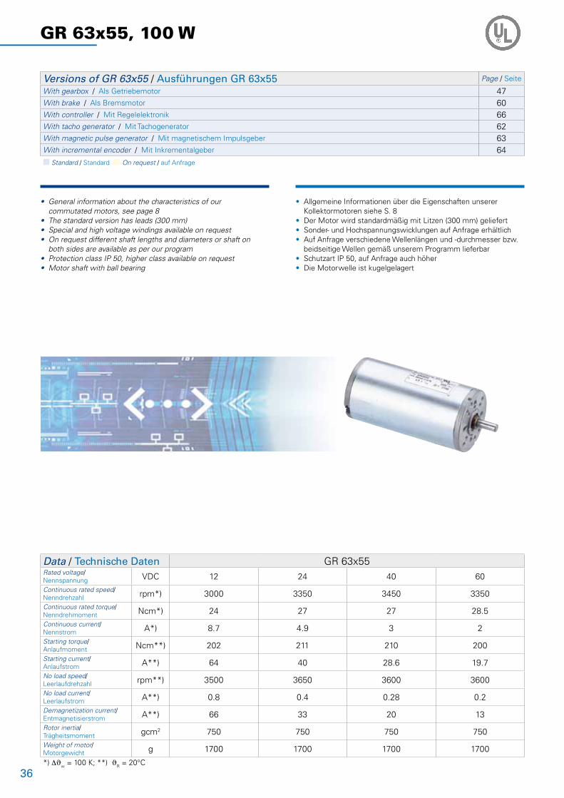
36
GR 63x55, 100 W
• General information about the characteristics of our commutated motors, see page 8• The standard version has leads (300 mm)• Special and high voltage windings available on request • On request different shaft lengths and diameters or shaft on both sides are available as per our program• Protection class IP 50, higher class available on request• Motor shaft with ball bearing
• Allgemeine Informationen über die Eigenschaften unserer Kollektormotoren siehe S. 8• Der Motor wird standardmäßig mit Litzen (300 mm) geliefert• Sonder- und Hochspannungswicklungen auf Anfrage erhältlich• Auf Anfrage verschiedene Wellenlängen und -durchmesser bzw. beidseitige Wellen gemäß unserem Programm lieferbar• Schutzart IP 50, auf Anfrage auch höher• Die Motorwelle ist kugelgelagert
Versions of GR 63x55 / Ausführungen GR 63x55 Page / Seite
With gearbox / Als Getriebemotor 47With brake / Als Bremsmotor 60With controller / Mit Regelelektronik 66With tacho generator / Mit Tachogenerator 62With magnetic pulse generator / Mit magnetischem Impulsgeber 63With incremental encoder / Mit Inkrementalgeber 64n Standard / Standard n On request / auf Anfrage
Data / Technische Daten GR 63x55Rated voltage/Nennspannung VDC 12 24 40 60
Continuous rated speed/Nenndrehzahl rpm*) 3000 3350 3450 3350
Continuous rated torque/Nenndrehmoment Ncm*) 24 27 27 28.5
Continuous current/Nennstrom A*) 8.7 4.9 3 2
Starting torque/Anlaufmoment Ncm**) 202 211 210 200
Starting current/Anlaufstrom A**) 64 40 28.6 19.7
No load speed/Leerlaufdrehzahl rpm**) 3500 3650 3600 3600
No load current/Leerlaufstrom A**) 0.8 0.4 0.28 0.2
Demagnetization current/Entmagnetisierstrom A**) 66 33 20 13
Rotor inertia/Trägheitsmoment gcm2 750 750 750 750
Weight of motor/Motorgewicht g 1700 1700 1700 1700
*) DJw = 100 K; **) JR = 20°C

37
GR 63x55, 100 W
Shaft / Welle front / vorne back / hinten
8 x 25 mm -
5 x 20 mm -
8 x 55 mm -
8 x 55 mm 8 x 55 mm
5 x 11 mm -
125±0.8
90°
90°45°
22.5°
4xM4
4xM4
4xM5
4xM4
Ø25 -0.04
Ø30 ±0.1
Ø40 ±0.1
Ø36 ±0.1
Ø49 ±0.1
0.2
0.2
0.2
0.2
A
A
A
A
Depth/Tiefe 7mm
B A
2 -0.3
125 ±0.8
5
25 ±0.5
Ø14
Ø8 g5
2 -0.3
-
BK
+
RD
7 ±2
300 ±30
0.06
0.03
A90°
90°
22.5°
Ø36 ±0.1
Ø40 ±0.1
Ø48 ±0.1
Ø25 -0.04
4xM40.2
0.2
0.2 B
B
BØ6
3±0.
3
Lead/Litze AWG18 UL Style1569 CSA TR 64
4x4.65-0.15
2x3.7-0.11
-40 0 40 80 120 160 200 240 280 320 360 400Ncm
7000
6000
5000
4000
3000
2000
1000
0
100
80
60
40
20
0
70
60
50
40
30
20
10
0 rated
spee
d/Dr
ehza
hl n (
rpm)
effic
iency
/Wirk
ungs
grad
η (%
)
curre
nt/S
trom
I (A)
MN
N = f (M)
J = f (M)
η
ϑR = 20°C
W= 100K
-40 0 40 80 120 160 200 240 280 320 360 400Ncm
7000
6000
5000
4000
3000
2000
1000
0
100
80
60
40
20
0
28
24
20
16
12
8
4
0 rated
spee
d/Dr
ehza
hl n (
rpm)
effic
iency
/Wirk
ungs
grad
η (%
)
curre
nt/S
trom
I (A)
MmaxMN
N = f (M) J = f (M)η
ϑR = 20°C
W= 100K
-40 0 40 80 120 160 200 240 280 320 360 400Ncm
7000
6000
5000
4000
3000
2000
1000
0
100
80
60
40
20
0
70
60
50
40
30
20
10
0 rated
spee
d/Dr
ehza
hl n (
rpm)
effic
iency
/Wirk
ungs
grad
η (%
)
curre
nt/S
trom
I (A)
MN Mmax
N = f (M) J = f (M)
η
ϑR = 20°C
W= 100K
-40 0 40 80 120 160 200 240 280 320 360 400Ncm
7000
6000
5000
4000
3000
2000
1000
0
100
80
60
40
20
0
70
60
50
40
30
20
10
0 rated
spee
d/Dr
ehza
hl n (
rpm)
effic
iency
/Wirk
ungs
grad
η (%
)
curre
nt/S
trom
I (A)
MN Mmax
N = f (M)
J = f (M)
η
ϑR = 20°C
W= 100K
Dimensions in mm / Maßzeichnung in mm
Characteristic diagram / Belastungskennlinien In accordance with EN 60034 Belastungskennlinien gezeichnet nach EN 60034
GR 63x55, 12V GR 63x55, 24V
GR 63x55, 40V GR 63x55, 60V
Faxial = max. 150NFradial = max. 150N

38
GR 63Sx55, 130 W
• General information about the characteristics of our commutated motors, see page 8• Use of stronger magnets• Black housing for better heat dissipation• The standard version has leads (300 mm)• Special and high voltage windings available on request • On request different shaft lengths and diameters or shaft on both sides are available as per our program• Protection class IP 50, higher class available on request• Motor shaft with ball bearing
• Allgemeine Informationen über die Eigenschaften unserer Kollektormotoren siehe S. 8• Verwendung stärkerer Magnete• Schwarzes Motorgehäuse für verbesserte Wärmeabfuhr• Der Motor wird standardmäßig mit Litzen (300 mm) geliefert• Sonder- und Hochspannungswicklungen auf Anfrage erhältlich• Auf Anfrage verschiedene Wellenlängen und -durchmesser bzw. beidseitige Wellen gemäß unserem Programm lieferbar• Schutzart IP 50, auf Anfrage auch höher• Die Motorwelle ist kugelgelagert
Versions of GR 63Sx55 / Ausführungen GR 63Sx55 Page / Seite
With gearbox / Als Getriebemotor 47With brake / Als Bremsmotor 60With controller / Mit Regelelektronik 66With tacho generator / Mit Tachogenerator 62With magnetic pulse generator / Mit magnetischem Impulsgeber 63With incremental encoder / Mit Inkrementalgeber 64n Standard / Standard n On request / auf Anfrage
preliminary data / vorläufige Daten
Data / Technische Daten GR 63Sx55Rated voltage/Nennspannung VDC 24
Continuous rated speed/Nenndrehzahl rpm*) 3350
Continuous rated torque/Nenndrehmoment Ncm*) 37
Continuous current/Nennstrom A*) 6.5
Starting torque/Anlaufmoment Ncm**) 335
Starting current/Anlaufstrom A**) 53.3
No load speed/Leerlaufdrehzahl rpm**) 3550
No load current/Leerlaufstrom A**) 0.6
Rotor inertia/Trägheitsmoment gcm2 750
Weight of motor/Motorgewicht g 1700
*) DJw = 100 K; **) JR = 20°C
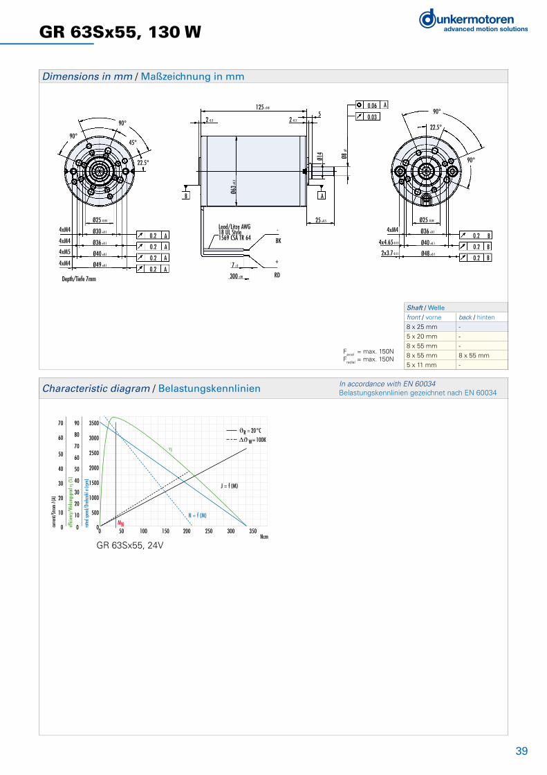
39
GR 63Sx55, 130 W
Shaft / Welle front / vorne back / hinten
8 x 25 mm -
5 x 20 mm -
8 x 55 mm -
8 x 55 mm 8 x 55 mm
5 x 11 mm -
125±0.8
90°
90°45°
22.5°
4xM4
4xM4
4xM5
4xM4
Ø25 -0.04
Ø30 ±0.1
Ø40 ±0.1
Ø36 ±0.1
Ø49 ±0.1
0.2
0.2
0.2
0.2
A
A
A
A
Depth/Tiefe 7mm
B A
2 -0.3
125 ±0.8
5
25 ±0.5
Ø14
Ø8 g5
2 -0.3
-
BK
+
RD
7 ±2
300 ±30
0.06
0.03
A90°
90°
22.5°
Ø36 ±0.1
Ø40 ±0.1
Ø48 ±0.1
Ø25 -0.04
4xM40.2
0.2
0.2 B
B
BØ6
3±0.
3
Lead/Litze AWG18 UL Style1569 CSA TR 64
4x4.65-0.15
2x3.7-0.11
0 50 100 150 200 250 300 350Ncm
3500
3000
2500
2000
1500
1000
500
0
90
80
70
60
50
40
30
20
10
0
70
60
50
40
30
20
10
0 rated
spee
d/Dr
ehza
hl n (
rpm)
effic
iency
/Wirk
ungs
grad
η (%
)
curre
nt/S
trom
I (A)
MN
N = f (M)
J = f (M)
η
ϑR = 20°C
W= 100K
Dimensions in mm / Maßzeichnung in mm
Characteristic diagram / Belastungskennlinien In accordance with EN 60034 Belastungskennlinien gezeichnet nach EN 60034
GR 63Sx55, 24V
Faxial = max. 150NFradial = max. 150N

40
GR 63 SI, 50 - 100 W
• General information about the characteristics of our commutated motors, see page 8• With integral speed controller (digital) for 4-quadrant drive and integral magnetic encoder• As standard, the target speed can be set using a 0...+10V analog voltage input• There are two digital inputs for selecting the four operating conditions: rotation clockwise/ counter-clockwise, controller block, and stop with holding torque• In addition, there are digital outputs, which provide a pulsed output with 16 impulses per revolution and an error signal. A direction of rotation signal (e.g. for monitoring position and speed) is available on request• Two fixed speeds, and acceleration and deacceleration ramps can be stored in memory• The motor is supplied as standard with a 12-pin connector• On request different shaft lenghts available• Protection class IP 54, IP 65 available on request• Motor shaft with ball bearing• For further technical data and information on terminal assignment, please see the operating manual at www.dunkermotoren.com (downloads)
Versions of GR 63 SI / Ausführungen GR 63 SI Page / Seite
With gearbox / Als Getriebemotor 474Q controller attached / Mit angebauter 4Q-Steuerungselektronik 40n Standard / Standard n On request / auf Anfrage
• Allgemeine Informationen über die Eigenschaften unserer Kollektormotoren siehe S. 8• Mit integriertem Speedcontroller (digital) für 4-Quadrantenbetrieb und integriertem magnetischen Impulsgeber• Die Drehzahlsollwertvorgabe erfolgt standardmäßig über einen Analogspannungseingang 0...+10V• Über zwei digitale Eingänge lassen sich die vier Betriebszustände Drehrichtung rechts, Drehrichtung links, Reglersperre und Stopp mit Haltemoment anwählen • Zusätzlich werden digitale Ausgänge herausgeführt, womit ein Pulsausgang mit 16 Impulsen pro Umdrehung und ein Störungssignal zur Verfügung stehen. Optional kann ein Drehrichtungssignal zur Verfügung gestellt werden• Das Abspeichern von 2 festen Geschwindigkeiten sowie von Beschleunigungs- und Bremsrampe ist möglich• Der Motor wird standardmäßig mit einem 12-poligen Stecker geliefert• Auf Anfrage verschiedene Wellenlängen lieferbar• Schutzart IP 54, optional IP 65• Die Motorwelle ist kugelgelagert• Weitere technische Daten sowie Informationen zur Anschlussbelegung finden Sie in der Betriebsanleitung unter www.dunkermotoren.de (downloads)
Data / Technische Daten GR 63x25 SI GR 63x55 SIRated voltage/Nennspannung VDC 12 24 40 12 24 40
Continuous rated speed/Nenndrehzahl rpm*) 3100 3300 3500 3000 3350 3450
Continuous rated torque/Nenndrehmoment Ncm*) 13.7 14 13.3 24 27 27
Continuous current/Nennstrom A*) 5.2 2.7 1.7 8.7 4.9 3
Starting torque/Anlaufmoment Ncm**) 82 108***) 118 202***) 211***) 210***)
Starting current/Anlaufstrom A**) 27 18***) 12 64***) 40***) 28.6***)
Electronic peak current/Zul. Spitzenstrom der Elektronik A**) 25 15 15 25 25 15
Rotor inertia/Trägheitsmoment gcm2 400 400 400 750 750 750
Weight of motor/Motorgewicht g 1400 1400 1400 1900 1900 1900
Voltage range/Max. zul. Spannungsbereich VDC 12 ... 40 12 ... 40 12 ... 40 12 ... 40 12 ... 40 12 ... 40
Recommended speed control range/Empfohlener Drehzahlregelbereich rpm 50 ... Rated speed / Nenndrehzahl
*) DJw = 100 K; **) JR = 20°C; ***) Will be restricted by peak current of the electronic / Wird durch den Spitzenstrom der Elektronik eingegrenzt
SPEED CONTROLLER
ATTACHED

41
GR 63 SI, 50 - 100 W
45±0.5 GR 63x25 SI 95±0.8
GR 63x55 SI 125±0.8
ca.16
8x25
ø 63
67.5°
Dimensions in mm / Maßzeichnung in mm
-10 0 10 20 30 40 50 60 70 80 90 100Ncm
7000
6000
5000
4000
3000
2000
1000
0
100
80
60
40
20
0
28
24
20
16
12
8
4
0 rated
spee
d/Dr
ehza
hl n (
rpm)
effic
iency
/Wirk
ungs
grad
η (%
)
curre
nt/S
trom
I (A)
MN
N = f (M)
J = f (M)
η
ϑR = 20°C
W= 100K
-20 0 20 40 60 80 100 120 140 160 180 200Ncm
7000
6000
5000
4000
3000
2000
1000
0
100
80
60
40
20
0
14
12
10
8
6
4
2
0 rated
spee
d/Dr
ehza
hl n (
rpm)
effic
iency
/Wirk
ungs
grad
η (%
)
curre
nt/S
trom
I (A)
MN
N = f (M)
J = f (M)
η
ϑR = 20°C
W= 100K
-20 0 20 40 60 80 100 120 140 160 180 200Ncm
7000
6000
5000
4000
3000
2000
1000
0
100
80
60
40
20
0
28
24
20
16
12
8
4
0 rated
spee
d/Dr
ehza
hl n (
rpm)
effic
iency
/Wirk
ungs
grad
η (%
)
curre
nt/S
trom
I (A)
MN
N = f (M)J = f (M)
η
ϑR = 20°C
W= 100K
-40 0 40 80 120 160 200 240 280 320 360 400Ncm
7000
6000
5000
4000
3000
2000
1000
0
100
80
60
40
20
0
70
60
50
40
30
20
10
0 rated
spee
d/Dr
ehza
hl n (
rpm)
effic
iency
/Wirk
ungs
grad
η (%
)
curre
nt/S
trom
I (A)
MN
N = f (M)
J = f (M)
η
ϑR = 20°C
W= 100K
-40 0 40 80 120 160 200 240 280 320 360 400Ncm
7000
6000
5000
4000
3000
2000
1000
0
100
80
60
40
20
0
70
60
50
40
30
20
10
0 rated
spee
d/Dr
ehza
hl n (
rpm)
effic
iency
/Wirk
ungs
grad
η (%
)
curre
nt/S
trom
I (A)
MN
N = f (M) J = f (M)
η
ϑR = 20°C
W= 100K
Mmax
-40 0 40 80 120 160 200 240 280 320 360 400Ncm
7000
6000
5000
4000
3000
2000
1000
0
100
80
60
40
20
0
70
60
50
40
30
20
10
0 rated
spee
d/Dr
ehza
hl n (
rpm)
effic
iency
/Wirk
ungs
grad
η (%
)
curre
nt/S
trom
I (A)
MN
N = f (M)
J = f (M)
η
ϑR = 20°C
W= 100K
Mmax
Characteristic diagram / Belastungskennlinien In accordance with EN 60034 Belastungskennlinien gezeichnet nach EN 60034
GR 63x25 SI, 12V GR 63x55 SI, 12V
GR 63x25 SI, 24V GR 63x55 SI, 24V
GR 63x55 SI, 40VGR 63x25 SI, 40V
Pin Signal
E + 24 V
F + 24 V
D IN 4
M OV
G OV
B IN 1
C IN 2
J N +
H N -
A OUT 1
K OUT 3
L IN 3

42
GR 80x40, 120 W
• General information about the characteristics of our commutated motors, see page 8• The standard version has leads (300 mm)• Special and high voltage windings available on request • On request different shaft lengths and diameters or shaft on both sides are available as per our program • Protection class IP 50, higher class available on request• Motor shaft with ball bearing
• Allgemeine Informationen über die Eigenschaften unserer Kollektormotoren siehe S. 8• Der Motor wird standardmäßig mit Litzen (300 mm) geliefert• Sonder- und Hochspannungswicklungen auf Anfrage erhältlich• Auf Anfrage verschiedene Wellenlängen und -durchmesser bzw. beidseitige Wellen gemäß unserem Programm lieferbar• Schutzart IP 50, auf Anfrage auch höher• Die Motorwelle ist kugelgelagert
Versions of GR 80x40 / Ausführungen GR 80x40 Page / Seite
With gearbox / Als Getriebemotor 47With brake / Als Bremsmotor 60With controller / Mit Regelelektronik 66With tacho generator / Mit Tachogenerator 62With magnetic pulse generator / Mit magnetischem Impulsgeber 63With incremental encoder / Mit Inkrementalgeber 64n Standard / Standard n On request / auf Anfrage
Data / Technische Daten GR 80x40Rated voltage/Nennspannung VDC 12 24 40 60
Continuous rated speed/Nenndrehzahl rpm*) 2700 2900 3500 3250
Continuous rated torque/Nenndrehmoment Ncm*) 34,5 35 35 35
Continuous current/Nennstrom A*) 11.5 5.8 4 2.5
Starting torque/Anlaufmoment Ncm**) 240 310 341 316
Starting current/Anlaufstrom A**) 67 46.4 38 26.4
No load speed/Leerlaufdrehzahl rpm**) 3100 3200 3450 3400
No load current/Leerlaufstrom A**) 0.93 0.46 0.33 0.24
Demagnetization current/Entmagnetisierstrom A**) 96 48 32 20
Rotor inertia/Trägheitsmoment gcm2 1800 1800 1800 1800
Weight of motor/Motorgewicht g 2800 2800 2800 2800
*) w = 100 K; **) R = 20°C

43
GR 80x40, 120 W
135±1
90°90°45°
22.5°
22.5°
0.2 A0.2 A0.2 A
4xM5
4xM6
Ø32 -0.055
Ø45 ±0.1
Ø60 ±0.1
Ø56 ±0.14xØ5.61-0.1
Depth/Tiefe 12mm
-
BK
+
RD
7 ±2
300 ±30
Lead/Litze UL Style1569 CSA TR 64U = 20VAWG16
U > 20VAWG18
B
135 ±1
353
Ø20 Ø12g5
A
30±1Ø8
0±0.
4
0.060.03
A 90°45°
22.5°
22.5°
Ø32 -0.05
Ø45 ±0.1
Ø56 ±0.1
Ø60 ±0.1
0.20.20.2
BBB
4xM5
4xØ5.61-0.1
4xØ5.61-0.1
-40 0 40 80 120 160 200 240 280 320 360 400Ncm
7000
6000
5000
4000
3000
2000
1000
0
100
80
60
40
20
0
70
60
50
40
30
20
10
0 rated
spee
d/Dr
ehza
hl n (
rpm)
effic
iency
/Wirk
ungs
grad
η (%
)
curre
nt/S
trom
I (A)
MN
N = f (M)
J = f (M)
η
ϑR = 20°C
W= 100K
-80 0 80 160 240 320 400 480 560 640 720 800Ncm
7000
6000
5000
4000
3000
2000
1000
0
100
80
60
40
20
0
28
24
20
16
12
8
4
0 rated
spee
d/Dr
ehza
hl n (
rpm)
effic
iency
/Wirk
ungs
grad
η (%
)
curre
nt/S
trom
I (A)
MN Mmax
N = f (M)
J = f (M)
η
ϑR = 20°C
W= 100K
-80 0 80 160 240 320 400 480 560 640 720 800Ncm
7000
6000
5000
4000
3000
2000
1000
0
100
80
60
40
20
0
70
60
50
40
30
20
10
0 rated
spee
d/Dr
ehza
hl n (
rpm)
effic
iency
/Wirk
ungs
grad
η (%
)
curre
nt/S
trom
I (A)
MN Mmax
N = f (M) J = f (M)
η
ϑR = 20°C
W= 100K
-40 0 40 80 120 160 200 240 280 320 360 400Ncm
7000
6000
5000
4000
3000
2000
1000
0
100
80
60
40
20
0
70
60
50
40
30
20
10
0 rated
spee
d/Dr
ehza
hl n (
rpm)
effic
iency
/Wirk
ungs
grad
η (%
)
curre
nt/S
trom
I (A)
MN
N = f (M)J = f (M)
η
ϑR = 20°C
W= 100K
Dimensions in mm / Maßzeichnung in mm
Characteristic diagram / Belastungskennlinien In accordance with EN 60034 Belastungskennlinien gezeichnet nach EN 60034
GR 80x40, 12V GR 80x40, 24V
GR 80x40, 40V GR 80x40, 60V
Shaft / Welle front / vorne back / hinten
12 x 30 mm -
12 x 30 mm 8 x 55 mm
Faxial = max. 180NFradial = max. 200N

44
GR 80x80, 240 W
• General information about the characteristics of our commutated motors, see page 8• The standard version has leads (300 mm)• Special and high voltage windings available on request • On request different shaft lengths and diameters or shaft on both sides are available as per our program • Protection class IP 50, higher class available on request• Motor shaft with ball bearing
• Allgemeine Informationen über die Eigenschaften unserer Kollektormotoren siehe S. 8• Der Motor wird standardmäßig mit Litzen (300 mm) geliefert• Sonder- und Hochspannungswicklungen auf Anfrage erhältlich• Auf Anfrage verschiedene Wellenlängen und -durchmesser bzw. beidseitige Wellen gemäß unserem Programm lieferbar• Schutzart IP 50, auf Anfrage auch höher• Die Motorwelle ist kugelgelagert
Versions of GR 80x80 / Ausführungen GR 80x80 Page / Seite
With gearbox / Als Getriebemotor 47With brake / Als Bremsmotor 60With controller / Mit Regelelektronik 66With tacho generator / Mit Tachogenerator 62With magnetic pulse generator / Mit magnetischem Impulsgeber 63With incremental encoder / Mit Inkrementalgeber 64n Standard / Standard n On request / auf Anfrage
Data / Technische Daten GR 80x80Rated voltage/Nennspannung VDC 24 40 60
Continuous rated speed/Nenndrehzahl rpm*) 3200 3100 3350
Continuous rated torque/Nenndrehmoment Ncm*) 62 62 63
Continuous current/Nennstrom A*) 10 6 4.2
Starting torque/Anlaufmoment Ncm**) 608 612 623
Starting current/Anlaufstrom A**) 112 73.6 60.5
No load speed/Leerlaufdrehzahl rpm**) 3200 3000 3100
No load current/Leerlaufstrom A**) 0.65 0.37 0.27
Demagnetization current/Entmagnetisierstrom A**) 91 51 36
Rotor inertia/Trägheitsmoment gcm2 3200 3200 3200
Weight of motor/Motorgewicht g 4000 4000 4000
*) DJw = 100 K; **) JR = 20°C

45
GR 80x80, 240 W
175±1
90°
90°45°22.5°
22.5°
4xM5
4xM6
Ø32 -0.055
Ø45 ±0.1
Ø60 ±0.1
Ø56 ±0.1
Depth/Tiefe 12mm
4xØ5.61-0.10.20.20.2
AAA
-
BK
+
RD
7 ±2
300 ±30
175 ±1
353
Ø20
Ø12
g5
30±1
B
Lead/Litze UL Style1569 CSA TR 64
U > 20VAWG18
U = 20VAWG16
Ø80±
0.4
A
0.060.03
A
0.20.20.2
BBB
Ø32 -0.05
Ø45 ±0.1
Ø60 ±0.1
Ø56 ±0.1
4xM5
4xØ5.61-0.1
4xØ5.61-0.1
90°45°
22.5°
22.5°
-100 0 100 200 300 400 500 600 700 800 900 1000Ncm
7000
6000
5000
4000
3000
2000
1000
0
100
80
60
40
20
0
70
60
50
40
30
20
10
0 rated
spee
d/Dr
ehza
hl n (
rpm)
effic
iency
/Wirk
ungs
grad
η (%
)
curre
nt/S
trom
I (A)
MN Mmax
N = f (M)
J = f (M)
η
-100 0 100 200 300 400 500 600 700 800 900 1000Ncm
7000
6000
5000
4000
3000
2000
1000
0
100
80
60
40
20
0
140
120
100
80
60
40
20
0 rated
spee
d/Dr
ehza
hl n (
rpm)
effic
iency
/Wirk
ungs
grad
η (%
)
curre
nt/S
trom
I (A)
MN Mmax
N = f (M) J = f (M)η
ϑR = 20°C
W= 100K
-80 0 80 160 240 320 400 480 560 640 720 800Ncm
7000
6000
5000
4000
3000
2000
1000
0
100
80
60
40
20
0
140
120
100
80
60
40
20
0 rated
spee
d/Dr
ehza
hl n (
rpm)
effic
iency
/Wirk
ungs
grad
η (%
)
curre
nt/S
trom
I (A)
MN Mmax
N = f (M)J = f (M)
η
ϑR = 20°C
W= 100K
ϑR = 20°C
W= 100K
Dimensions in mm / Maßzeichnung in mm
Characteristic diagram / Belastungskennlinien In accordance with EN 60034 Belastungskennlinien gezeichnet nach EN 60034
GR 80x80, 24V GR 80x80, 40V
GR 80x80, 60V
Shaft / Welle front / vorne back / hinten
12 x 30 mm -
12 x 30 mm 8 x 55 mm
Faxial = max. 180NFradial = max. 200N

46
Notes / Notizen

47
PLG/SG Gears for DC Motors / PLG/SG Getriebe für DC-Motoren
Worm gearboxes (SG) are noted for their very quiet running. The worm-gear shaft has bearings on both sides. The gear components, made of bronze, steel or plastic, and the lubrication ensure a long service life at the rated torque. In many applications, the location of the output shaft at 90° to the motor shaft provides an optimum design solution. On request, worm-gearboxes can be supplied with a hollow output shaft.
Planetary gearboxes (PLG) have the highest continuous torque capacity of all types of gearbox; at the same time they have a very compact design, low weight and excellent efficiency. In our planetary gearboxes is a variety of different materials depending on customer requirements combined they are available with the torque range up to 160 Nm, and many ratios from 4:1 to 710.5:1.
The ring gear is both plastic or metal available and forms the housing of the gearbox. The planet gears are made of plastic, steel, or steel sintered, they are straight or helical geared available, the self-centering planet gears ensure a symmetrical power distribution. The output shaft is made of steel and supported by duplex bearing so it withstands high axial and radial loads. With the exception of PLG 24 and PLG 30 (they have self-lubricating cylinder bearings) are ball bearings used. For extreme loads Special versions with welded shaft are also available. Our H (hybrid) planetary gearboxes are for especially quiet running, the planet gear of the first reduction are plastic and helical geared. At the PLG 60 are the planet gears of the 2nd Stage also plastic and helical geared.
The gearboxes are customized, e.g. for use in especially low ambient temperatures, or as high-power gearboxes with reinforced output shafts, or with special lubricants for very long service life. For information on the selection of suitable motors and gearboxes, please see pages 8-9 in this catalog. This will enable you to make an initial selection on the basis of speed and load ranges. On request, we will adapt a drive precisely to your operating conditions.
Schneckengetriebe (SG) zeichnen sich durch hohe Laufruhe aus. Die Schneckenradwelle ist beidseitig gelagert. Die Verzahnungsteile aus Bronze, Stahl oder Kunststoff sowie eine Fettschmierung gewährleisten eine hohe Lebensdauer bei den angegebenen Nenndrehmomenten. Bei vielen Anwendungen ist die um 90° gegenüber der Motorwelle versetzte Getriebewelle von baulichen Gege-benheiten her optimal. Auf Anfrage sind Schneckengetriebe auch mit Hohlwelle lieferbar.
Planetengetriebe (PLG) haben die höchsten zulässigen Dauerdrehmomente aller Getriebe bei gleichzeitig sehr kompakter Bauform, geringem Gewicht und ausgezeichnetem Wirkungsgrad. Bei unseren Planetengetrieben ist eine Vielzahl von verschiedensten Materialien je nach Kundenanforderungen kombinierbar, wobei der Drehmomentbereich bis zu 160 Nm beträgt, und Untersetzungen von 4:1 bis 710,5:1 erhältlich sind.
Das Hohlrad ist sowohl in Kunststoff als auch in Metall verfügbar und dient gleichzeitig als Getriebegehäuse. Die Planetenräder sind aus Kunststoff, Stahl oder Stahl gesintert, gerad- oder schrägverzahnt erhältlich, und garantieren durch Selbstzentrierung eine symmetrische Kraftverteilung.Die Getriebeabtriebswelle ist aus Stahl und zweifach gelagert um hohe axiale und radiale Kräfte aufzunehmen,mit Ausnahme vom PLG 24 und PLG 30 (selbstschmierende Zylinderlager) werden Kugellager verwendet. Sonderaus-führungen mit geschweißter Welle für extreme Belastungen sind ebenfalls erhältlich.Für besondere Laufruhe sind bei unseren H (Hybrid) Planetengetrieben die Planetenräder der 1. Stufe aus Kunststoff und schrägverzahnt. Beim PLG 60 sind die Planetenräder der 2. Stufe ebenfalls aus Kunststoff und schrägverzahnt.
Die Getriebe sind in zahlreichen Sonderausführungen lieferbar, z. B. für den Einsatz bei besonders niedrigen Umgebungstemperaturen oder als Hochleistungsgetriebe mit verstärkter Ausgangswelle und spezieller Schmierung für höchste Lebensdauer. Informationen zur Auswahl des passenden Motors und Getriebes finden Sie auf der Seite 8-9 in diesem Katalog. Der Katalog gestattet eine Vorauswahl in Drehzahl und Lastbereichen. Eine exakte Anpassung des Antriebs an Ihre Betriebsbedingungen erfolgt auf Anfrage.

48
PLG 24 - Ring gear and Planet gears steel / Hohlrad und Planetenräder StahlReduction ratio/Untersetzungsverhältnis 4.33 6 18.75 33.2 46 81.2 143.8 199.3 276 353
Efficiency/Wirkungsgrad 0.9 0.81 0.73
Number of stages/Stufenzahl 1 2 3
Continuous torque/Dauerdrehmoment Ncm 30 45 60
Weight of gearbox/Getriebegewicht kg 0.019 0.025 0.035
Axial load/radial load/Axiallast/Radiallast N 5/12 5/12 5/12
PLG 30 - Ring gear plastic / Hohlrad KunststoffReduction ratio/Untersetzungsverhältnis
G30.2*G30.1* 4.5 6.25 8 15 20.25 28.125 36 50 91.12 126.56 162 175.78 288 400
Reduction ratio/Untersetzungsverhältnis
G30.0* 4.5 6.25 15 20.25 28.125 36 50 91.12 126.56 162 288 400
Efficiency/Wirkungsgrad 0.9 0.81 0.73
Number of stages/Stufenzahl 1 2 3
Continuous torque/Dauerdrehmoment Ncm 40 80 180
Weight of gearbox/Getriebegewicht kg 0.05 0.08 0.09
Axial load/radial load/Axiallast/Radiallast N 10/24 10/24 10/24
PLG 32 - Ring gear steel / Hohlrad StahlReduction ratio/Untersetzungsverhältnis
G30.2*G30.1* 4.5 6.25 8 15 20.25 28.125 36 39 50 91.12 126.5 162 225 288 312.5 400 512 589.5 1012.5
Reduction ratio/Untersetzungsverhältnis
G30.0*GR42* 4.5 6.25 8 15 20.25 28.125 36 39 50 91.12 126.5 162 288 312.5 400 512 1012.5
Efficiency/Wirkungsgrad 0.9 0.81 0.73
Number of stages/Stufenzahl 1 2 3
Continuous torque/Dauerdrehmoment Ncm 40 150 400
Weight of gearbox/Getriebegewicht kg 0.14 0.18 0.23
Axial load/radial load/Axiallast/Radiallast N 30/100 30/100 30/100
PLG 42 K - Ring gear plastic / Hohlrad KunststoffReduction ratio/Untersetzungsverhältnis
G30.2*G30.1*G30.0*
6.25 8 32 50 64 312.5 400 512
Reduction ratio/Untersetzungsverhältnis
GR42* 4 6.25 8 16 25 32 50 64 100 128 156 200 256 312.5 400 512
Efficiency/Wirkungsgrad 0.9 0.81 0.73
Number of stages/Stufenzahl 1 2 3
Continuous torque/Dauerdrehmoment Ncm 70 130 300
Weight of gearbox/Getriebegewicht kg 0.16 0.20 0.25
Axial load/radial load/Axiallast/Radiallast N 150/230 150/230 150/230
PLG 30 H - Low NoiseReduction ratio/Untersetzungsverhältnis 4.5 6.25 8 11.5 15 20.25 36 50 64 71.875 91.12 126.5 162 225 288 400 512 575
Efficiency/Wirkungsgrad 0.9 0.81 0.73
Number of stages/Stufenzahl 1 2 3
Continuous torque/Dauerdrehmoment Ncm 40 80 180
Weight of gearbox/Getriebegewicht kg 0.08 0.11 0.12
Axial load/radial load/Axiallast/Radiallast N 10/24 10/24 10/24
PLG 32 H - Low NoiseReduction ratio/Untersetzungsverhältnis 4.5 6.25 8 11.5 15 20.25 36 50 64 71.875 91.12 126.5 162 225 288 400 512 575
Efficiency/Wirkungsgrad 0.9 0.81 0.73
Number of stages/Stufenzahl 1 2 3
Continuous torque/Dauerdrehmoment Ncm 40 150 400
Weight of gearbox/Getriebegewicht kg 0.17 0.21 0.24
Axial load/radial load/Axiallast/Radiallast N 30/100 30/100 30/100
Planetary Gearboxes PLG / Planetengetriebe PLG

49
PLG 52 - Ring gear Steel / Hohlrad StahlReduction ratio/Untersetzungsverhältnis 4.5 6.25 8 15 20.25 28.12 36 50 64 91.12 126.5 162 225 288 400 512
Efficiency/Wirkungsgrad 0.9 0.81 0.73
Number of stages/Stufenzahl 1 2 3
Continuous torque/Dauerdrehmoment Ncm 120 800 2400
Weight of gearbox/Getriebegewicht kg 0.56 0.72 0.88
Axial load/radial load/Axiallast/Radiallast N 500/350 500/350 500/350
PLG 60 - Low NoiseReduction ratio/Untersetzungsverhältnis
GR51*GR53* 3 4 7 10 12 16 21 30 40 49 70
Reduction ratio/Untersetzungsverhältnis
GR63*GR80* 3 4 7 10 12 16 21 30 40 49 70
Efficiency/Wirkungsgrad 0.9 0.81
Number of stages/Stufenzahl 1 2
Continuous torque/Dauerdrehmoment Ncm 500 2500
Weight of gearbox/Getriebegewicht kg 0.55 0.78
Axial load/radial load/Axiallast/Radiallast N 500/350 500/350
PLG 42 S - Ring gear steel / Hohlrad StahlReduction ratio/Untersetzungsverhältnis 4 6.25 8 16 25 32 50 64 100 128 156 200 256 312.5 400 512
Efficiency/Wirkungsgrad 0.9 0.81 0.73
Number of stages/Stufenzahl 1 2 3
Continuous torque/Dauerdrehmoment Ncm
90 (plastic planet gears, Kunststoff-Planetenräder) /350
600 1400
Weight of gearbox/Getriebegewicht kg 0.27 0.37 0.47
Axial load/radial load/Axiallast/Radiallast N 150/250 150/250 150/250
PLG 52 H - Low NoiseReduction ratio/Untersetzungsverhältnis 4.5 6.25 8 15 20.25 28.12 36 50 64 91.12 126.5 162 225 288 400 512
Efficiency/Wirkungsgrad 0.9 0.81 0.73
Number of stages/Stufenzahl 1 2 3
Continuous torque/Dauerdrehmoment Ncm 120 800 2400
Weight of gearbox/Getriebegewicht kg 0.6 0.72 0.88
Axial load/radial load/Axiallast/Radiallast N 500/350 500/350 500/350
PLG 63 - Ring gear steel / Hohlrad StahlReduction ratio/Untersetzungsverhältnis 3 4 7 10 14.5 16.8 29.4 35 42 50 60.9 70 101.5 70.56 84 100 147 175 210 250 304.5 362.5 426.3 507.5 710.5
Efficiency/Wirkungsgrad 0.85 0.72 0.61
Number of stages/Stufenzahl 1 2 3
Continuous torque/Dauerdrehmoment Ncm
500 (plastic planet gears, Kunststoff-Planetenräder) / 1500
7000 10000
Weight of gearbox/Getriebegewicht kg 1.1 2.2 3.3
Axial load/radial load/Axiallast/Radiallast N 800/800 800/800 800/800
n Standard / Standard n On request / auf Anfrage
* Ratios depending on combined motor* Untersetzungen abhängig vom kombinierten Motor
PLG 75 - Ring gear steel / Hohlrad StahlReduction ratio/Untersetzungsverhältnis 4 5.5 7 10 14.5 16.8 23.1 27.5 29.4 35 42 50 60.9 70 101.5 70.56 84 100 115.5 147 175 210 250 304.5 362.5 426.3 507.5 710.5
Efficiency/Wirkungsgrad 0.85 0.72 0.61
Number of stages/Stufenzahl 1 2 3
Continuous torque/Dauerdrehmoment Ncm 2500 12000 16000
Weight of gearbox/Getriebegewicht kg 1.5 2.6 3.7
Axial load/radial load/Axiallast/Radiallast N 1000/1000 1000/1000 1000/1000
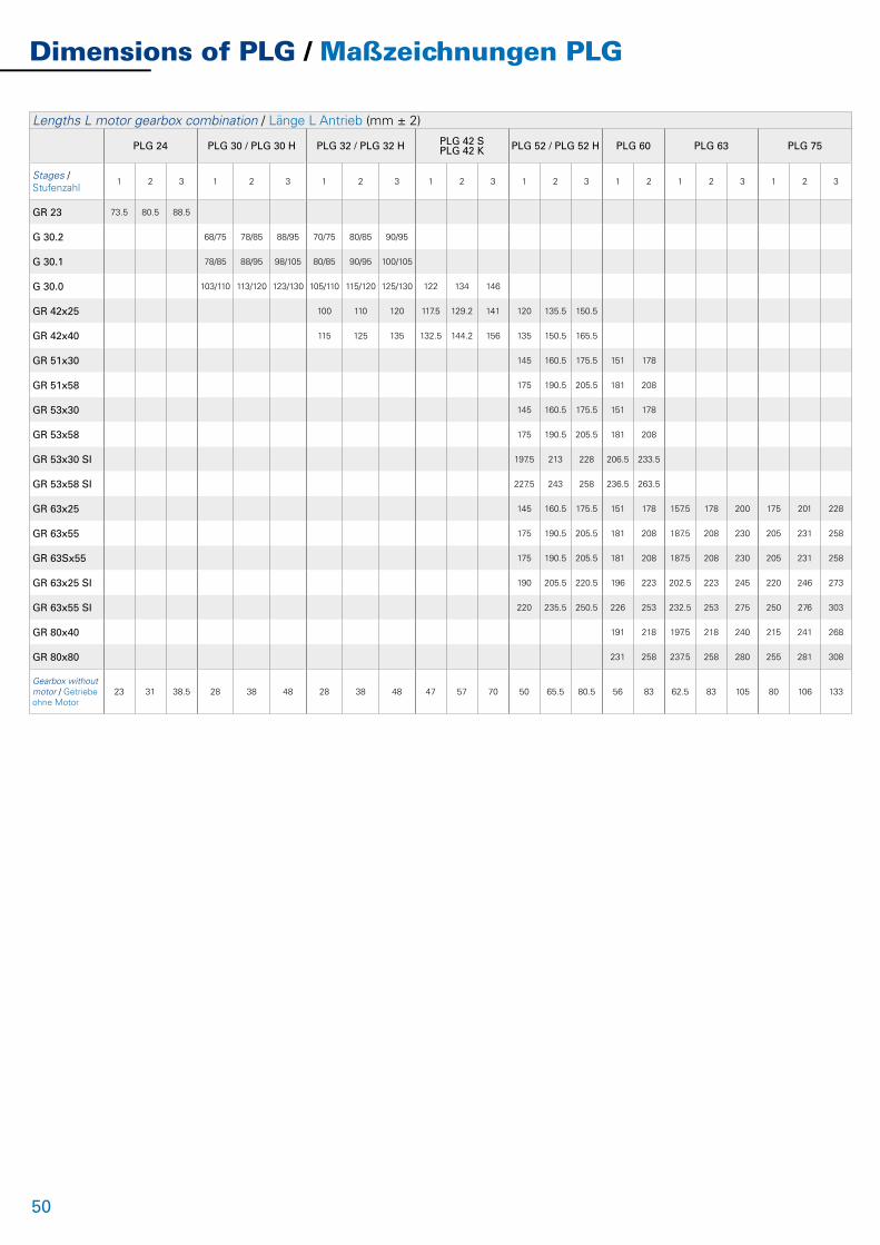
50
Lengths L motor gearbox combination / Länge L Antrieb (mm ± 2)
PLG 24 PLG 30 / PLG 30 H PLG 32 / PLG 32 H PLG 42 S PLG 42 K PLG 52 / PLG 52 H PLG 60 PLG 63 PLG 75
Stages / Stufenzahl
1 2 3 1 2 3 1 2 3 1 2 3 1 2 3 1 2 1 2 3 1 2 3
GR 23 73.5 80.5 88.5
G 30.2 68/75 78/85 88/95 70/75 80/85 90/95
G 30.1 78/85 88/95 98/105 80/85 90/95 100/105
G 30.0 103/110 113/120 123/130 105/110 115/120 125/130 122 134 146
GR 42x25 100 110 120 117.5 129.2 141 120 135.5 150.5
GR 42x40 115 125 135 132.5 144.2 156 135 150.5 165.5
GR 51x30 145 160.5 175.5 151 178
GR 51x58 175 190.5 205.5 181 208
GR 53x30 145 160.5 175.5 151 178
GR 53x58 175 190.5 205.5 181 208
GR 53x30 SI 197.5 213 228 206.5 233.5
GR 53x58 SI 227.5 243 258 236.5 263.5
GR 63x25 145 160.5 175.5 151 178 157.5 178 200 175 201 228
GR 63x55 175 190.5 205.5 181 208 187.5 208 230 205 231 258
GR 63Sx55 175 190.5 205.5 181 208 187.5 208 230 205 231 258
GR 63x25 SI 190 205.5 220.5 196 223 202.5 223 245 220 246 273
GR 63x55 SI 220 235.5 250.5 226 253 232.5 253 275 250 276 303
GR 80x40 191 218 197.5 218 240 215 241 268
GR 80x80 231 258 237.5 258 280 255 281 308
Gearbox withoutmotor / Getriebe ohne Motor
23 31 38.5 28 38 48 28 38 48 47 57 70 50 65.5 80.5 56 83 62.5 83 105 80 106 133
Dimensions of PLG / Maßzeichnungen PLG
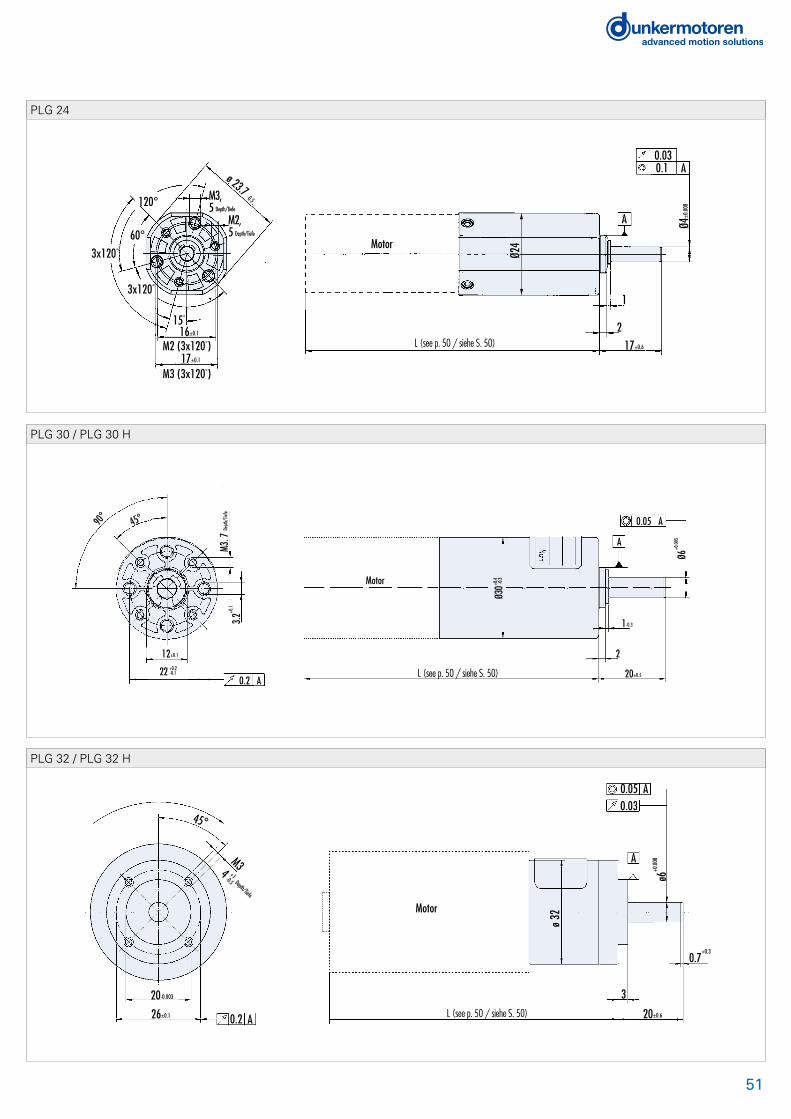
51
120°
60°3x120°
3x120°
M3, 5 Depth/Tiefe
M2, 5 Depth/Tiefe
15°
16±0.1
17±0.1
M3 (3x120°)
M2 (3x120°)
ø 23.7 -0.5
Motor
Ø24
0.1 A0.03
A Ø4±0
.008
1
217±0.6
PLG 24
Motor
90°
M3.7
Depth
/Tief
e
3.2+0
.1
12±0.1
Motor
L 20±0.5
2
1-0.3
Ø6+0
.005
45°
+0.222 -0.1
0.2 A
0.05 A
A
+0.4
Ø30-
0.3
PLG 30 / PLG 30 H
45°
M3+14
-0.5 Depth/Tiefe
20-0.003
26±0.1 0.2 A
Motor
L
0.05 A0.03
ø32
20±0.6
0.7+0.3
ø6+0
.008A
3
PLG 32 / PLG 32 H
L (see p. 50 / siehe S. 50)
L (see p. 50 / siehe S. 50)
L (see p. 50 / siehe S. 50)

52
Motor
M 3M 3M 4
AA0.2
0.236 ±0.15
32 ±0.15
25 -0.052
Ø 42
Woodruff key/Scheibenfeder2 x 3.7
0.030.05 A
Ø 8 +
0.001
A
0.8 +0.4
2
25 -0.5
+0.00
7
0
12
PLG 42 S / PLG 42 K
M5
7.5 Dept
h/Tiefe
40±0.1
0.2 A
0.05 A
0.03
Ø52
C
A
B
Scheibenfeder/Woodruff key 4 x 6.5
DIN 6888 Series A12
3
25±1
0 Ø32 -0.039 +0.00
8
Ø1
2 +0.0
03
Nom
Motor
PLG 52 / PLG 52 H
Motor
52 ±0.1
40 h7
M 5
0.2 A
A5
32 ±0.8
Parallel key/Passfeder5 x 5 x 20 DIN 6885
Ø 15
h5
0.03
A0.06
Ø 60
-0.5
PLG 60
Dimensions of PLG / Maßzeichnungen PLG
L (see p. 50 / siehe S. 50)
L (see p. 50 / siehe S. 50)
L (see p. 50 / siehe S. 50)

53
Ø 52±0.1
Parallel Key/Passfeder 5x5x20DIN 6885-A
0.2 A
M510 tief/deep
90°
45°
Motor
3.5
Ø63
L (see p. 50 / siehe S. 50) 32±1
2.526
0.06 A
0.03
A
B
B
C
Ø 15
h7Ø
40-0
.011
PLG 63
Motor
Parallel Key/Passfeder 6x6x28DIN 6885
A0.2
3.5
90°
Ø 65±0.1
Ø75±
0.4
A
B
49±1
B
Ø19 h
7
5B
A0.050.03
Centring/Zentrierung M6 18 deep/tief
M6 16 deep/tief
4045°
Ø 50 -0.050+0.011
PLG 75
• Dimension drawings of complete drives (motor and gear) are available at www.dunkermotoren.com (Products -> direct selection)• Maßzeichnungen von kompletten Antrieben (Motor-Getriebe-Kombinationen) erhalten Sie auf unserer Homepage: www.dunkermotoren.de (Produkte -> direkte Produktauswahl)
L (see p. 50 / siehe S. 50)

54
Worm Gearboxes SG / Schneckengetriebe SG
Due to its characteristic design, the worm gearbox should generally not be used in applications with the motor pointing down and the gearbox above the motor. In these cases, please contact us or one of our sales partners.
SG 45The gearbox output shaft runs in ball bearings as standard. There is a single output shaft on the left-hand side.
SG 62The gearbox output shaft runs in self-lubricating sintered bushes, as standard, there is a single output shaft on the left-hand side. Special versions are available with ball bearings.
SG 65This very slim gearbox is available on request in batches above 500 pieces.
SG 65 KSThe worm gear and output shaft is made of plastic. This gearbox is available on request for projects.
SG 80/ SG 80 KThe gearbox output shaft runs in ball bearings as standard. There is a single output shaft on the left-hand side. Special versions with a non metallic worm wheel are also available.
SG 80 H (hollow shaft)Gearbox with hollow output shaft. Gear parts in bronze and steel.
SGF 120The gearbox output shaft runs in ball bearings as standard. There is a single output shaft on the left-hand side. Special versions with a non metallic worm wheel are also available.
SG 120/ SK 120 KFoot-mounting gearbox with die-cast zinc housing.Special versions with a non metallic worm wheel are also available.
SG 120 H (hollow shaft)Gearbox with hollow output shaft. Available on request in batches above 100 pieces.
SG 80 + PLG 52.0The SG 80 is also available with planetary gearbox PLG 52.0 as the output stage. This is just one example of the numerous possible gearbox combinations.
On all worm gearboxes, as standard, there is only one output shaft, which is on the left when looking from the gearbox end (WL1). Special versions are possible.
Bei Anwendungsfällen mit Überkopfmontage der Schnecken-radgetriebe wenden Sie sich bitte an uns oder an einen unserer Vertriebspartner.
SG 45Die Getriebe-Abtriebswelle ist serienmäßig kugelgelagert und einseitig links ausgeführt.
SG 62Die Getriebe-Abtriebswelle ist in selbstschmierender Sinter-buchse gelagert und serienmäßig einseitig links ausgeführt. In Sonderausführung ist auch die Kugellagerung möglich.
SG 65Dieses sehr schlanke Getriebe ist auf Anfrage für Losgrößen ab 500 erhältlich.
SG 65 KSDas Schneckenrad und die Getriebe-Abtriebswelle bestehen aus Kunststoff. Dieses Getriebe ist auf Anfrage für Projekte erhältlich.
SG 80/ SG 80 KDie Getriebe-Abtriebswelle ist serienmäßig kugelgelagert und einseitig links ausgeführt. In Sonderausführungen sind auch Versionen mit Verzahnungsteilen aus Kunststoff erhältlich.
SG 80 H (Hohlwelle) Getriebe in Hohlwellenausführung. Verzahnungsteile aus Bronze und Stahl.
SGF 120Die Getriebe-Abtriebswelle ist serienmäßig kugelgelagert und einseitig links ausgeführt. Bei diesen Ausführungen handelt es sich um Flanschausführungen. In Sonderausführungen sind auch Versionen mit Verzahnungsteilen aus Kunststoff erhältlich.
SG 120/ SG 120KDas Zinkdruckgußgehäuse ist als Fußausführung konzipiert. In Sonderausführungen sind auch Versionen mit Verzahnungs-teilen aus Kunststoff erhältlich.
SG/ SGF 120 H (Hohlwelle)Getriebe in Hohlwellenausführung. Auf Anfrage für Losgrößen ab 100 erhältlich.
SG 80 + PLG 52.0Das SG 80 ist auch mit nachgeschaltetem Planetengetriebe PLG 52.0 erhältlich. Dies ist nur ein Beispiel zahlreicher möglicher Getriebekombinationen.
Bei allen Schneckengetrieben ist die Abtriebswelle serienmäßig, auf das Getriebe gesehen, einseitig nach links ausgeführt (WL1). Sonderausführungen sind möglich.
WL1 Standard version,shaft on left
WL1 StandardausführungWelle links
WL2 Special version, shaft on right
WL2 SonderausführungWelle rechts
WL3 Special version, shafts on both sides
WL3 SonderausführungWelle beidseitig

55
SG 80 / SG 80 K / SG 80 HReduction ratio/Untersetzungsverhältnis
SG 80SG 80 H 5 10 15 24 38 50 75
Reduction ratio/Untersetzungsverhältnis
SG 80 K 10 15
Efficiency/Wirkungsgrad 0.7 0.65 0.55 0.5 0.4 0.35 0.25
Continuous torque/Dauerdrehmoment Ncm 400 (no metallic gears, Kunststoff-Schneckenräder)/1000
Weight of gearbox/Getriebegewicht kg 0.4
Axial load/radial load/Axiallast/Radiallast N 300/350
Mounting not allowed via gearbox cover / Adaption über Getriebedeckel nicht zulässig
SG 45Reduction ratio/Untersetzungsverhältnis 5 10 15 25 30 40 50 75
Efficiency/Wirkungsgrad 0.79 0.69 0.6 0.48 0.43 0.3 0.38 0.23
Continuous torque/Dauerdrehmoment Ncm 75
Weight of gearbox/Getriebegewicht kg 0.2
Axial load/radial load/Axiallast/Radiallast N 100/200
SG 120 / SG 120 KReduction ratio/Untersetzungsverhältnis
SG 120 8 10 15 20 30 40 50 60 70 80
Reduction ratio/Untersetzungsverhältnis
SG 120 K 10 15
Efficiency/Wirkungsgrad 0.7 0.7 0.65 0.55 0.5 0.4 0.35 0.3 0.28 0.25
Continuous torque/Dauerdrehmoment Ncm 1500 (plastic worm gears, Kunststoff-Schneckenräder)/3000
Weight of gearbox/Getriebegewicht kg 2.0
Axial load/radial load/Axiallast/Radiallast N 300/500
SG 80 + PLG 52.0 CombinationTotal reduction ratio/Gesamtuntersetzungs-verhältnis
22 31 45 62 101 180 250 360 500 750 1200 1900 2500 4000 6000 9600 15200 20000 30000
Reduction ratio/UntersetzungsverhältnisSG 80
5 5 10 10 5 5 5 10 10 15 24 38 50 10 15 24 38 50 75
Reduction ratio/UntersetzungsverhältnisPLG 52
4.5 6.25 4.5 6.25 20.25 36 50 36 50 50 50 50 50 400 400 400 400 400 400
Continuous torque/Dauerdrehmoment Ncm 700 800 2400
Weight of gearbox/Getriebegewicht kg 0.95 1.12 1.28
Axial load/radial load/Axiallast/Radiallast N 500/350 500/350 500/350
SG 62Reduction ratio/Untersetzungsverhältnis 8 15 23 35 46 72
Efficiency/Wirkungsgrad 0.6 0.55 0.5 0.45 0.4 0.3
Continuous torque/Dauerdrehmoment Ncm 150
Weight of gearbox/Getriebegewicht kg 0.3
Axial load/radial load/Axiallast/Radiallast N 40/40
Worm Gearboxes SG / Schneckengetriebe SG
n Standard / Standard n On request / auf Anfrage

56
Lengths L motor gearbox combination / Länge L Antrieb (mm ± 2)
SG 45 SG 62 SG 80 SG 120
GR 42x25 115 121
GR 42x40 130 136
GR 51x30 140 146
GR 51x58 170 176
GR 53x30 140 146
GR 53x58 170 176
GR 53x30 SI 195.5 201.5
GR 53x58 SI 225.5 231.5
GR 63x25 166 205
GR 63x55 196 235
GR 63Sx55 196 235
GR 63x25 SI 211 250
GR 63x55 SI 241 280
GR 80x40 245
GR 80x80 285
Dimensions of SG / Maßzeichnungen SG
Motor
Ø 8 g
5
Ø 18
-0.04
Ø 18
-0.04 15
13
1719
22
15 ±0.1
2xM3; 5 Depth/Tiefe
8x M34 tief
L 45
45°
255.5
25 ±0.1
2xM3; 7Depth/Tiefe
15 ±0.1
30Ø 26 -0.04
SG 45
L (see p. 56 / siehe S. 56)

57
Motor
2
2543
21.5
12.5
2
20
2546
12.525±0.1
40±0
.1
Ø8g5
Ø18-0
.04
4xM4*8 Depth/Tiefe
0.08
A0.03
2040±0.1
32±0.1
24.6±0.1
18-0.04 4xM4*8 Depth/Tiefe
2523
.5
M3, 8 Depth/Tiefe
51(26) 20
2.810 tief
SG 62
0.08 A0.03
A
12
3.530±1
1530±0.1
5641
20.5
3.5
Ø10g5
50±0
.1
Ø25-0
.0428
M5, 8 tief
Motor
(36) 35
36±0.1
50±0.1
3531
≈15Ø62
71
TiefeDepth/
M4.8 Tiefe4xM5,8 Depth/
SG 80
Output shaft/Abtriebswelle
10+0.1
≤ R0.2
11.4
+0.1
3D10
50±0
.1
Ø25-0
.04
3.5 M5x4, 8 Depth/Tiefe
3.5
1530±0.1
56
*Ø25-0
.04
2841
20.5
71(36) 35
≈15
Ø62
Motor
3135
36±0.1
50±0.1
L
Depth/Tiefe
Depth/
M4,8 TiefeM5x4,8
SG 80 H
L (see p. 56 / siehe S. 56)
L (see p. 56 / siehe S. 56)
L (see p. 56 / siehe S. 56)
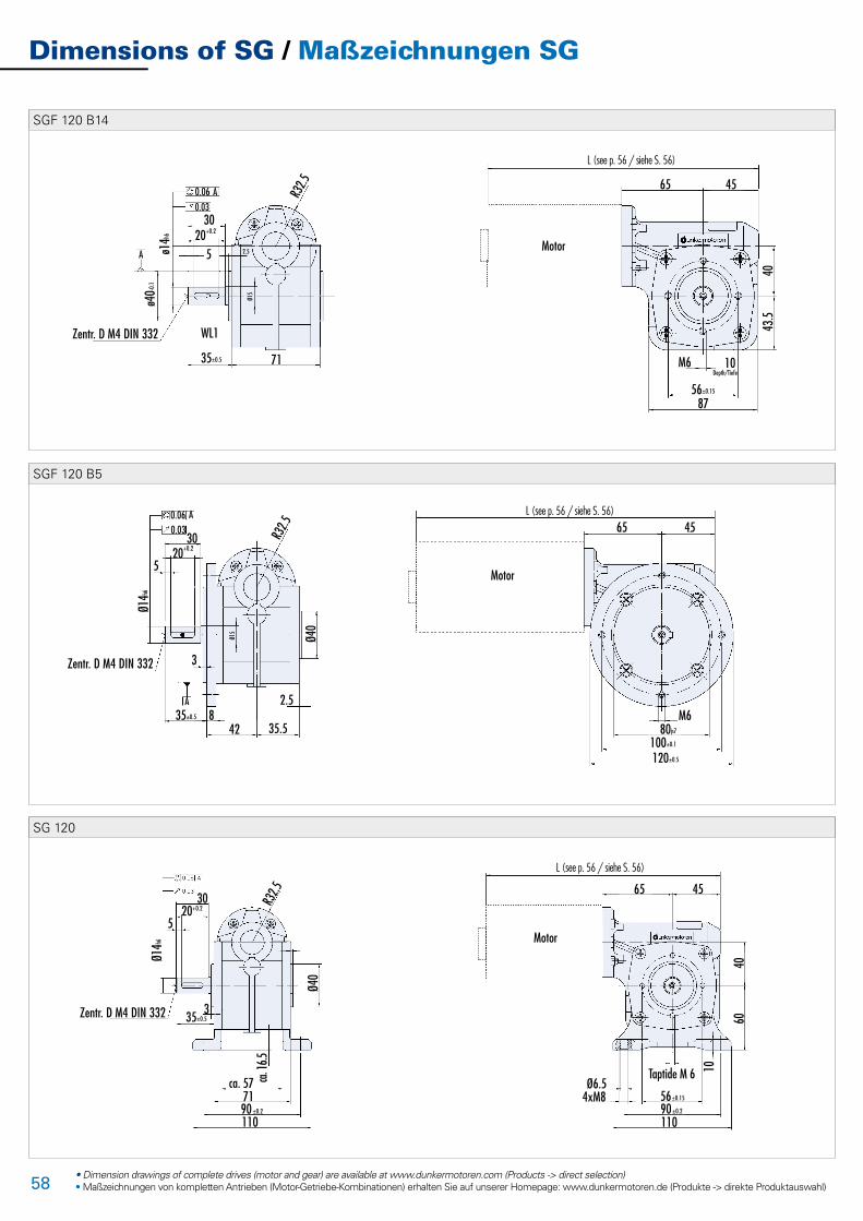
58
L
65 45
43.5
40
8756±0.15
M6 10Depth/Tiefe
Motor
0.06 A0.03
35±0.5
WL1
ø40-0
.1
ø14h6
3020+0.2
5 2.5Ø1
5A
R32.5
Zentr. D M4 DIN 332
71
SGF 120 B14
L
65 45
Motor
M6
120±0.5
100±0.1
80js7
0.06 A
R32.5
Zentr. D M4 DIN 332
0.0330
20+0.2
Ø40
35.5428
3
5
2.535±0.5
Ø14h6
Ø15
A
SGF 120 B5
SG 120
Dimensions of SG / Maßzeichnungen SG
• Dimension drawings of complete drives (motor and gear) are available at www.dunkermotoren.com (Products -> direct selection)• Maßzeichnungen von kompletten Antrieben (Motor-Getriebe-Kombinationen) erhalten Sie auf unserer Homepage: www.dunkermotoren.de (Produkte -> direkte Produktauswahl)
R32.5
Ø40
110
ca. 57 ca.16
.5
65 45
Motor
4060
Ø6.54xM8 56±0.15
90±0.2
110
M6
10
71
Zentr. D M4 DIN 332
3020+0.2
5
35±0.5
Ø14h6
3
90±0.2
Taptide M 6
L (see p. 56 / siehe S. 56)
L (see p. 56 / siehe S. 56)
L (see p. 56 / siehe S. 56)

59
Notes / Notizen

60
Brakes for GR/G Motors / Bremsen für GR/G-Motoren
DC motors in the GR/G range can be fitted with rotor brakes. As standard, power-off brakes are employed, i.e. the brake operates when no voltage is applied and releases when current flows. Power-on brakes are available on request. IP 54 covers are available for all brakes. Combinations of incremental encodersand brakes are possible. Depending on the motor-brake combination, degrees of protection up to IP 65 are pos-sible. To protect the DC contacts in your control system against arcing, we recommend the use of a freewheeling diode.
E 38 RSpring-applied brake, operates when no current is applied. The special design of this brake makes it suitable for both static and dynamic braking. Axial play in the motor has no influence on brake performance.
E 46 A This power-on brake is only available on request for batches above 500 pieces.
E 90 RSpring-applied brake, operates when no current is applied. The special design of this brake makes it suitable for both static and dynamic braking. Axial play in the motor has no influence on brake performance. Manual release of the brake is available as an option (not on versions where a cover is fitted).
E 100 AThis power-on brake (permanent-magnet brake) is only available on request.
E 100 R This power-off brake (permanent-magnet brake) is only available on request.
The Performance data values are for reference only, and in some cases may vary. When brakes are designed-in, installation circumstances, braking torque fluctuations, friction work, breaking-in behaviour and wear-out as well as environmental conditions need to be reviewed and adjusted carefully.In case of temperature fluctuations, which can, for example, cause dew, the braking torque may decrease considerably, If the brake is applied for a very long period. Appropriate countermeasures need to be taken by the user.
Kollektorgleichstrommotoren der Baureihe GR/G können mit Ankerstoppbremsen ausgerüstet werden. Es werden stand-ardmäßig Ruhestrombremsen geliefert, d. h. die Bremsung erfolgt, wenn keine Spannung anliegt bzw. öffnet, wenn Strom fließt. Arbeitsstrombremsen sind auf Anfrage erhält-lich. Für alle Bremsen sind Schutzhauben IP 54 erhältlich. Kombinationen von Inkrementalgebern und Bremsen sind möglich. Abhängig von der Motor-Bremse-Kombination sind sogar Schutzarten bis IP 65 möglich. Zum Schutz des Gleich-stromkontaktes Ihrer Ansteuerung vor Kontaktabbrand wird der Einsatz einer Freilaufdiode empfohlen.
E 38 RDie Federdruckbremse bremst im stromlosen Zustand. Durch die spezielle Konstruktion kann die Bremse sowohl als statische oder dynamische Bremse eingesetzt werden. Axiales Motorspiel hat keinen Einfluß auf die Brems- funktion.
E 46 A Diese Arbeitsstrombremse ist nur auf Anfrage für Los-größen ab 500 Stück erhältlich.
E 90 RDie Federdruckbremse bremst im stromlosen Zustand. Durch die spezielle Konstruktion kann die Bremse sowohl als statische oder dynamische Bremse eingesetzt werden. Axiales Motorspiel hat keinen Einfluß auf die Bremsfunk-tion. Eine manuelle Entriegelung der Bremse ist optional erhältlich (nicht bei Versionen mit Schutzhaube).
E 100 ADiese Arbeitsstrombremse (Permanentmagnetbremse) ist nur auf Anfrage erhältlich.
E 100 R Diese Ruhestrombremse (Permanentmagnetbremse) ist nur auf Anfrage erhältlich.
Die Leistungsdaten sind Richtwerte, die in Einzelfällen abweichen können. Bei der Auswahl der Bremsen sind Einbausituationen, Bremsmomentschwankungen, Reibarbeit Einlaufverhalten und Verschleiß sowie Umgebungs- bedingungen sorgfältig zu prüfen und abzustimmen.Bei Temperaturschwankungen kann, z.B. durch Betauung, das Drehmoment stark abfallen. Bei längerem Stillstand können sich die Reibbeläge an den Reibflächen festsetzen. Entsprechende Gegenmaßnahmen sind durch den Anwender vorzusehen.

61
Data / Technische Daten E 38 R E 46 A E 90 R E 100 A E 100 ROperating voltage/Betriebsspannung VDC 24 24 24 24 24
Braking torque/Bremsmoment Ncm 20 40 100 150 150
Current consumption/Stromaufnahme mA 200 260 310 330 380
Power input/Aufnahmeleistung W 5 6.3 7.5 8 9
Turn on time/Einschaltzeit ms 20 7.5 30 15 15
Turn off time/Ausschaltzeit ms 5 5 1.5 11 11
Protection class/Schutzart IP 20 20 20 00 00
Insulation class/Isolierstoffklasse
- B B E B B
Weight/Gewicht kg 0.12 0.1 0.5 0.28 0.28
n Standard / Standard n On request / auf Anfrage
MotorMotorØ 1
L1
Brakes / Bremsen IP 20
Length / Längen (L in mm ± 0.5)
E 38 + G 30 E 38 + GR 42 E 46 + GR 53 E 46 + GR 63 E 90 + GR 53/63/80 E 100+ GR 53/63/80
Ø1 38 38 56 56 59 41
L1 31 26 32.5 24 42 47
Length / Längen (L in mm ± 0.5)
E 38 + G 42 E 90 + GR 53/63 E 90 + GR 80
Ø1 52 63 80
L1 81.5 105 119.5
L2 46.5 70 77.5
Pin
1 Motor ( - )
2 Motor (+)
3 Brake (+)
4 Brake ( - )
MotorMotorØ 1
L1
L2
Brakes with cover / Bremsen mit Schutzhaube IP 54
• Dimension drawings of complete drives (motor and gear) are available at www.dunkermotoren.com (Products -> direct selection)• Maßzeichnungen von kompletten Antrieben (Motor-Getriebe-Kombinationen) erhalten Sie auf unserer Homepage: www.dunkermotoren.de (Produkte -> direkte Produktauswahl)
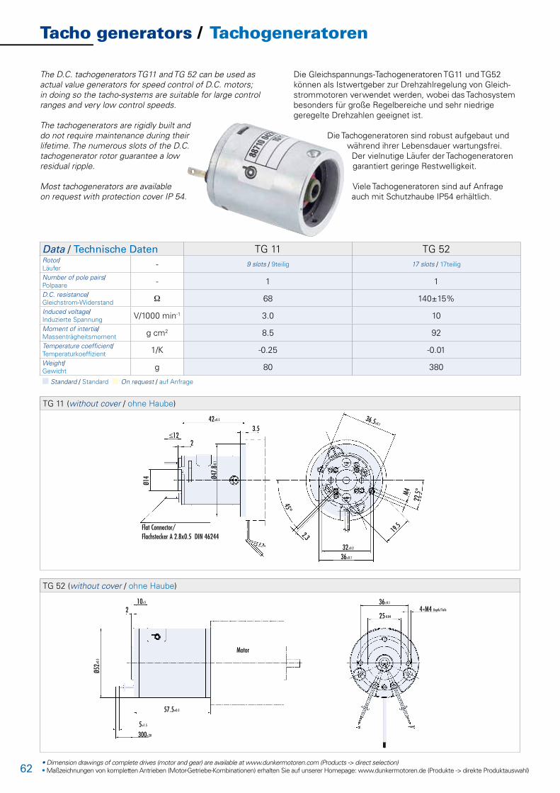
62
Tacho generators / Tachogeneratoren
The D.C. tachogenerators TG11 and TG 52 can be used as actual value generators for speed control of D.C. motors; in doing so the tacho-systems are suitable for large control ranges and very low control speeds. The tachogenerators are rigidly built and do not require maintenance during their lifetime. The numerous slots of the D.C. tachogenerator rotor guarantee a low residual ripple.
Most tachogenerators are available on request with protection cover IP 54.
Die Gleichspannungs-Tachogeneratoren TG11 und TG52 können als Istwertgeber zur Drehzahlregelung von Gleich-strommotoren verwendet werden, wobei das Tachosystem besonders für große Regelbereiche und sehr niedrige geregelte Drehzahlen geeignet ist.
Die Tachogeneratoren sind robust aufgebaut und während ihrer Lebensdauer wartungsfrei. Der vielnutige Läufer der Tachogeneratoren garantiert geringe Restwelligkeit.
Viele Tachogeneratoren sind auf Anfrage auch mit Schutzhaube IP54 erhältlich.
Data / Technische Daten TG 11 TG 52Rotor/Läufer - 9 slots / 9teilig 17 slots / 17teilig
Number of pole pairs/Polpaare - 1 1
D.C. resistance/Gleichstrom-Widerstand W 68 140±15%
Induced voltage/Induzierte Spannung V/1000 min-1 3.0 10
Moment of intertia/Massenträgheitsmoment g cm2 8.5 92
Temperature coefficient/Temperaturkoeffizient 1/K -0.25 -0.01
Weight/Gewicht g 80 380
n Standard / Standard n On request / auf Anfrage
42±0.5
3.5
2≤12
Ø14 Ø4
7.8-0
.1
Flat Connector/Flachstecker A 2.8x0.5 DIN 46244
19.5
36.5±0.1
45°
2.3
32±0.2
36±0.1
22.5°M4
TG 11 (without cover / ohne Haube)
10±5
2
Ø52±
0.5
57.5±0.5
5±1.5
300±20
Motor
36±0.1
25-0.04
4*M4 Depth/Tiefe
TG 52 (without cover / ohne Haube)
• Dimension drawings of complete drives (motor and gear) are available at www.dunkermotoren.com (Products -> direct selection)• Maßzeichnungen von kompletten Antrieben (Motor-Getriebe-Kombinationen) erhalten Sie auf unserer Homepage: www.dunkermotoren.de (Produkte -> direkte Produktauswahl)

63• Dimension drawings of complete drives (motor and gear) are available at www.dunkermotoren.com (Products -> direct selection)• Maßzeichnungen von kompletten Antrieben (Motor-Getriebe-Kombinationen) erhalten Sie auf unserer Homepage: www.dunkermotoren.de (Produkte -> direkte Produktauswahl)
The magnetic pulse generators are applicable for speed detection, speed control and positioning in combination with corresponding electronics.
The magnetic pulse generators are connected mechani-cally to the motor and transmit a series of impulses corresponding to the motor speed and direction via external leeds.
The non-contact magnetic generator is equipped with hall sensors and magnet ring and is wearfree. A safe operation is possible due to the simple design, the magnetic signal activation and the starting signal which can be varied by the supply voltage.
Most magnetic pulse generators are available on request with protection cover IP 54.
Die magnetischen Impulsgeber eignen sich für die Drehzahl-erfassung, Drehzahlregelung und Positionierung in Verbind-ung mit einer entsprechenden Elektronik.
Die Geber sind mit den Motoren kraftschlüssig ver-bunden. Der elektrische Anschluß erfolgt über
herausgeführte Litzen.
Die Magnetgeber arbeiten mit Hall-Sen-soren und Magnetring berührungslos und verschleißfrei. Der einfache Aufbau, die magnetische Signalerzeugung und das
Ausgangssignal, das über die angelegte Versorgungsspannung variiert werden kann,
ermöglichen einen sicheren Betrieb.
Viele Impulsgeber sind auf Anfrage auch mit Schutzhaube IP54 erhältlich.
Data / Technische Daten MG 2 ME 52 ME 80Pull-up resistor/Pull-Up Widerstand - no / nein yes / ja yes / ja
Output signal/Ausgangssignale - 2 square wave signals, in phase quadrature / 2 Rechtecksignale, 90°C phasenversetzt
Impulses per revolution/Impulszahl pro Umdrehung ppr 2 2,8,12
Operating voltage/Versorgungsspannung VDC UN = 12 (5 ... 24)
Operating current/Stromaufnahme mA max. 12 (U=12V)
Deviation of pulse width/Abweichung der Pulsbreite - max. 15°
Deviation of phase shift/Abweichung der Phasenverschiebung - max. 15°
Output voltage/Ausgangsspannung (low level) VDC max. 0.4 (20mA)
Signal rise time/Signalanstiegszeit ns 85 typ; 400 max. (U=12V, RL=820W)
Signal decay time/Signalabfallzeit ns 60 typ; 400 max. (CL=20pF)
Operating temperature/Betriebstemperatur °C –40 ... + 85
n Standard / Standard n On request / auf Anfrage
4 Leads/ Litzen AWG24
30
13
MG 2 (without cover / ohne Haube)
Magnetic pulse generators / Magnetische Impulsgeber
L1
L2
4 Leads/ Litzen AWG24
ME 52 / ME 80 (without cover / ohne Haube)
Lead MG
green B
brown +5V...+24V
blue 0V
yellow A
Lead ME
red +5V...+24V
yellow A
black 0V
green B
Length / Länge (L in mm ±1)
ME52+GR42 ME52+GR53/63 ME80 + GR80
L1 23 18 18
L2 42 42 52

64
Where stringent demands are placed on the quality of regu-lation and positioning accuracy, the DC-motors are available with a digital incremental encoder.
Incremental encoders have no sliding contacts and are not subject to wear. A light-emitting diode, a slotted metal disc, and a photo-diode array form a photoelectric circuit. An internal logic produces two square-wave signals phased at 90° to each other from the output of the photo-diodes, with or without a reference impulse.
Where the cable length between the motor and encoder is more than 2.5 m, we recommend use of the RE .. TI, fitted with an additional power booster. The standard supply voltage for the incre-mental encoder is 5 VDC. As specials, 24V versions are also available. An IP54 cover is recommended as protec-tion against external influences.
Bei hohen Anforderungen an die Regelbarkeit und Positio-niergenauigkeit sind die Gleichstrommotoren mit einem digitalen Inkrementalgeber erhältlich.
Die Inkrementalgeber arbeiten berührungslos und verschleißfrei. Eine Leuchtdiode, eine metallische
Schlitzscheibe und ein Fotodiodenarray bilden eine Lichtschranke. Eine interne Logik erzeugt
aus dem Signal der Fotodioden zwei um 90° verschobene Rechtecksignale, ohne bzw. mit Referenzimpuls.
Bei Kabellängen von mehr als 2,5 m zwischen Motor und Geber empfiehlt sich der Einsatz eines RE .. TI, ausgerüstet mit einem zusätz-lichen Leistungstreiber. Die Versorgungsspannung der Inkrementalgeber beträgt standardmäßig 5 VDC. In Sonderaus-führungen sind auch 24V-Versionen erhältlich.
Zum Schutz vor äußeren Einflüssen empfiehlt sich die Verwendung einer IP54-Schutzhaube.
Incremental Encoders for GR/G Motors / Inkrementalgeber für GR/G-Motoren
Data / Technische Daten RE 20 RE 30-2 RE 30-3 RE 30-3 TI RE 56-3 RE 56-3 TIOperating voltage/Versorgungsspannung VDC 5 5 5 5 5 5
Impulses per revolution/Impulszahl pro Umdrehung ppr 100 100 ... 512 100 ... 512 100 ... 512 1000 1000
Signal rise time/Signalanstiegszeit ns 200 200 180 180 180 180
Signal decay time/Signalabfallzeit ns* 50 50 40 40 40 40
Current consumption/Stromaufnahme mA max. 25 17 (max. 40) 57 (max. 85) max. 85 57 (max. 85) max. 85
Output voltage/Ausgangsspannung (low--level) VDC max. 0.4 (3.2 mA) max. 0.4 (3.2 mA) max. 0.4 (3.9 mA) max. 0.5 (20 mA) max. 0.4 (3.9 mA) max. 0.5 (20 mA)
Output voltage/Ausgangsspannung (high--level) VDC min. 2.4 (40 µA) min. 2.4 (40 µA) min. 2.4 (200 µA) min. 2.4 (200 µA) min. 2.4 (200 µA) min. 2.4 (200 µA)
Max. output current/max. Ausgangsstrom mA 20 5 5 70 5 70
Operating temperature/Betriebstemperatur °C - 20 ... + 85 - 40 ... + 100 - 40 ... + 100 - 40 ... + 100 - 40 ... + 100 - 40 ... + 100
Protection class/Schutzart IP 30 30 30 30 30 30
*) CL = 25pF; R= 11kW
n Standard / Standard n On request / auf Anfrage
B
A
Q
QD-
B
A
EX - OR
Wiring suggestions / Schaltungsvorschlag
Clockwise/counter-cw. detection / Rechts-/Links-Erkennung Pulse doubling / Impuls-Verdoppelung
High = cw. / rechts
High = ccw. / links4 impulses per rev / 4 Impulse pro Umdrehung

65
Incremental Encoders for GR/G Motors / Inkrementalgeber für GR/G-Motoren
18.5±0.5 Ø44
rot
16
schwarz
35°
30
RE 20 (without cover / ohne Haube) IP 30
20±0.5
41±0
.5
ca.6
Ø56±0.5
31±0.5
22.5°
RE 56 / RE 56 TI (without cover / ohne Haube) IP 30
21.8±0.5
2.5
43.5
15
30±0.5
45°
RE 30 / RE 30 TI (without cover / ohne Haube) IP 30
Lca. 42
Ø63
IEC 130 - 9 Binder Series 723/423 8pin
4pin DIN 43650
GR 63 + RE 30 / RE 30 TI (+E90) (with cover / mit Haube) IP 54
Lca. 35
Ø80+
1
30
4pin DIN 43650
Binder Typ 723 DIN 45328 8pin
GR 80 + RE 30 / RE 30 TI (+E90) (with cover / mit Haube) IP 54
GND
+5V
R R R
B
A
Index
RE 30
5
4
3
2
1
2K7
2K7
2K7
RE 30-3 (Connection example / Beschaltungsvorschlag)
• Dimension drawings of complete drives (motor and gear) are available at www.dunkermotoren.com (Products -> direct selection)• Maßzeichnungen von kompletten Antrieben (Motor-Getriebe-Kombinationen) erhalten Sie auf unserer Homepage: www.dunkermotoren.de (Produkte -> direkte Produktauswahl)
Pin RE 20
1 GND 0V
2 -
3 A
4 Vcc 5V
5 B
Pin RE 56-X
1 GND 0V
2 I (56-3)
3 A
4 Vcc 5V
5 B
Pin RE 56-X TI
6 A
7 /B
8 B
9 /I (56-3)
10 I (56-3)
Pin RE 56-X TI
1 n.c.
2 Vcc 5V
3 GND 0V
4 n.c.
5 /A
Pin RE 30-X
1 GND 0V
2 I (30-3)
3 A
4 Vcc 5V
5 B
Pin RE 30-X TI
6 A
7 /B
8 B
9 /I (30-3)
10 I (30-3)
Pin RE 30-X TI
1 n.c.
2 Vcc 5V
3 GND 0V
4 n.c.
5 /A
RE 30 RE 30 + E 90
40 L 79 L
Pin 30-3TI
1 A
2 B
3 Vcc 5V
4 GND 0V
Pin 30-3TI
5 I
6 /A
7 /B
8 /I
Pin GR/E90
1 Motor (-)
2 Motor (+)
3 Asto E (+)
4 Asto E (-)
RE 30 RE 30 + E 90
55 L 77.5 L
Pin 30-3TI
1 A
2 B
3 Vcc 5V
4 GND 0V
Pin 30-3TI
5 I
6 /A
7 /B
8 /I
Pin GR/E90
1 Motor (-)
2 Motor (+)
3 Asto E (+)
4 Asto E (-)

66
Controller RS 200 / Regelelektronik RS 200
The RS200 electronic controller is a transistor servo-control-ler for brushed permanent-magnet DC motors. The RS200 electronics enables a motor to drive and brake in one direction (2-quadrant operation). The braking effect is achieved by short-circuit braking.
The RS200 servo-controller is an analogue speed regula-tor that operates on a current-regulation basis. The pulse-width-modulated electronics have a high efficiency and are thus very compact. To ensure compliance with current EMC standards, a filter is included, and the controller has a complete electromagnetic protected housing. These features combined with the use of shielded cables ensure that the requirements of EN55011 Cl. B are fulfilled. There is also a fuse on the PCB which interrupts the mains supply if overloaded.
The RS200 electronic controller only needs a single sup-ply voltage that lies within a generous range. All necessary auxiliary voltages, including those for supplying external components are generated from this internal power-supply.
The user has a choice of methods of providing the actual-speed signal, either with a DC tacho-generator, a one or two-channel rotary encoder, or by using the speed-propor-tional EMC of the motor with compensation for the cur-rent-dependent armature-voltage drop (IxR). To select the desired type of operation (DC tacho, encoder or IxR), the user simply has to put a bridging plug in the correct place in the connector strip. For applications with less stringent de-mands on speed control (above 500 1/min), it is possible to set speed substantially independent of load by using EMC without the need for a DC tacho or encoder. This EMC regulation is a low-cost solution and is also eco-nomical on space. For speeds of rotation above 50 1/min, speed feedback can be achieved using the RE30 or RE56 rotary encoders. The widest speed-control range with the greatest precision of regulation is achieved by using one of the DC tacho-generators TG11 or TG 52. For specific projects, use of the MG2 sensor is also possible.
When the servo-controller is ready for operation, a LED indicator is illuminated, and there is also a digital output signal. Where it is necessary to use an external ballast circuit, there is a suitable signal available at the connector to the PCB.
For connecting the servo-controller, there is a 16-pole phoenix-style connector with screw/plug terminals (available as an accessory). For specific projects, the RS200 electronic controller can be supplied with a 32-pin strip to DIN41612 so that it is suitable for use in 19”-racks.
For further technical data and information on terminal assignment, please see the operating manual at
www.dunkermotoren.com (download area)
Die Regelelektronik RS200 ist ein Transistor-Servoregler zur Speisung von bürstenbehafteten Gleichstrommotoren mit Permanenterregung. Die RS200-Elektronik gestattet das Treiben und Bremsen des Motors in einer Drehrichtung (2Q-Betrieb). Der Bremsbetrieb erfolgt als Kurzschlußbremsung.
Der Servoregler RS200 arbeitet analog als Drehzahlregler mit unterlagerter Stromregelung. Die pulsweiten- modulierte Betriebsart der Regelelektronik ermöglicht einen hohen Wirkungsgrad und damit einen kompakten Aufbau. Zur Einhaltung der gültigen EMV-Normen ist ein Filter integriert und der Aufbau ist elektromagnetisch geschirmt aufgebaut. Durch diese Maßnahmen und den Einsatz ge-schirmter Kabel wird EN55011 Kl. B erreicht. Eine netztren-nende Schmelzsicherung ist ebenfalls auf der Leiterplatte vorhanden.
Die Regelelektronik RS200 benötigt nur eine Versorgungs-spannung in einem großen Versorgungspannungsbereich. Aus dieser Spannung werden alle erforderlichen Hilfsspan-nungen erzeugt, die auch zur Versorgung der externen Bedienelemente und der Istwertgeber an den Klemmen zur Verfügung steht.
Der Anwender hat die freie Wahl der Rückführung des Drehzahlistwertes entweder mit einem Gleichspannungs-tachogenerator, einem ein- bzw. zweikanaligen Inkremental-geber oder der drehzahlproportionalen EMK des Motors mit Kompensierung des stromabhängigen Ankerspannungsab-falls (IxR). Durch Setzen des Kurzschlußsteckers an der Bedienungssteckleiste wählt der Anwender die gewünschte Betriebsart mit DC-Tacho, encoder oder IxR. Für Anwen-dungsfälle mit geringeren Anforderungen (größer 500 U/min) an die Drehzahlregelgenauigkeit ist mit Hilfe der EMK-Regelung eine weitgehend lastunabhängige Einstellung der Drehzahl ohne DC-Tacho oder Inkrementalgeber gegeben. Diese EMK-Regelung ist preiswert und platzsparend. Für Drehzahlen im Bereich größer 50 U/min ist eine Drehzahl-rückführung mit den Inkrementalgebern RE30 und RE56 einsetzbar. Den größten Drehzahlregelbereich mit bester Regelgüte erhält man mit Einsatz der DC-Tachogeneratoren TG11 und TG52. Projektbezogen ist ebenfalls der Einsatz des MG2-Istwertgebers möglich.
Die Betriebsbereitschaft des Servoreglers wird über eine LED-Anzeige und durch ein extern herausgeführtes digitales Ausgangssignal angezeigt. Um bei Bedarf eine externe Ballastschaltung anzusteuern steht ein entsprechendes Signal am Kartenanschluß zur Verfügung.
Der Anschluß der Regelelektronik erfolgt mit einem 16-poligen Schraubsteckverbinder (als Zubehör lieferbar). Projektbezogen ist die RS200-Regelelektronik auch mit einer 32-poligen Stiftleiste nach DIN41612 lieferbar und dadurch für die 19”-Einschubtechnik geeignet.
Weitere technische Daten sowie Informationen zur An-schlussbelegung finden Sie in der Betriebsanleitung unter
www.dunkermotoren.de (download-Bereich)

67
Controller RS 200 / Regelelektronik RS 200Supply voltage/ Versorgungsspannung 12V ≤ U ≤ 50V with max. 5% ripple / mit maximal 5% Restwelligkeit
Under/overvoltage protection/Unter-Überspannungserkennung for / für 10 V > U > 60 V
Auxiliary voltage/Hilfsspannungen +5V/100mA and / und +12V/40mA
Ballast circuit/Ballastschaltung 5 Watt effective for / wirksam für 54V < U < 57V, externally extendable / extern erweiterbar
Fault output/Fehlerausgang 0/ 10V and / und LED
Max. continuous current/Max. Dauerstrom 0 < I < 7A adjustable / einstellbar
Max dynamic current/Maximalstrom 0 < I < 15A adjustable / einstellbar
Fuses/Absicherung 8A (MT) installed / (mittelträge) eingebaut
DC tacho voltage/ DC-Tachospannung 0 ... +60V
Rotary incremental encoder/Inkrementalgeber
5V auxiliary supply generated and automatic evaluation of 1 or 2-channel square-wave signals /
5V-Versorgung durch vorhandene Hilfsspannung und automatischer Auswertung von 1- oder 2-kanaligen Rechtecksignalen
Analog speed value/ Analog-Drehzahlsollwertvorgabe 0 ... 10V
Recommended operating range/Empfohlener Arbeitsbereich
– with RXI regulation minimum speed of rotation: 500 1/min– with rotary incremental encoder (e.g. RE30) minimum speed of rotation: 50 1/min– with tacho-generator (e.g. TG11) minimum speed of rotation: 5 1/min
– mit EMK-Regelung minimale Drehzahl: 500 U/min– mit Inkrementalgeber (z. B. RE30) minimale Drehzahl: 50 U/min– mit Tachogeneraotor (z. B. TG11) minimale Drehzahl: 5 U/min
Accuracy of regulation/Regelgenauigkeit
by Speed loading from 0 to 80% of torque– with IxR regulation 10%– with rotary encoder (e.g. RE30) 1%– with tacho-generator (e.g. TG11) 1%
Drehzahlbelastung von 0 auf 80% des Momentes– mit IxR-Regelung 10%– mit Inkrementalgeber (z. B. RE30) 1%– mit Tachogenerator (z. B. TG11) 1%
Heat-sink temperature/Kühlkörpertemperatur
max. 80°C thereafter current is automatically adjusted /max. 80°C danach automatische Stromanpassung
Speed-target ramp/Drehzahlsollwertrampe adjustable from ca. 0 - 10 s / von ca. 0 - 10 sek einstellbar
Interference suppression/Funkentstörung to EN55011 Class B / nach EN55011 Klasse B
Max. speed of rotation/Max. Drehzahl 6000/min
P-speed-control amplification/P-Drehzahlregelverstärkung 0 < Pn < 9 adjustable / einstellbar
Protection class/Schutzart IP00
Ambient temperature/Umgebungstemperatur 0 ≤ d ≤ 40°C
Dimensions/Abmessungen 163 x 100 x 28 mm
Potentiometer arrangementPotentiometer Einstellungen

68
BGE 3508/6005
• External controller for DC motors from Dunkermotoren• Extremely compact 4-quadrant controller to control brush-type and brushless DC-motors (BGE 3508/6005)• Optionally as freely programmable version with integral Motion Process Unit. Allows stand-alone-operation or representation of stand-alone-networks (BGE 3508/6005)• CAN interface (DSP402)• The controller is protected against over-voltage, low-voltage and over-temperature cut-off• The controller can be fixed by boreholes on the side• Three connection plugs are included in delivery
For further technical data and information on terminal assignment, please see the operating manual at www.dunkermotoren.com (downloads).
• Externe Regler für DC-Motoren von Dunkermotoren• Extrem kompakter 4-Quandranten-Regler zur Ansteuerung von bürstenlosen oder bürstenbehafteten DC-Motoren (BGE 3508/6005)• Optional als frei programmierbare Variante mit integrierter Motion Process Unit. Diese Ausführung ermöglicht auch Stand-alone-Betrieb oder die Darstellung von Stand-alone- Netzwerken (BGE 3508/6005)• Mit CAN-Schnittstelle (Geräteprofil DSP402, Protokoll DS301)• Die Elektronik verfügt über Überspannungs-, Unterspannungs- und Übertemperaturabschaltung• Die Befestigung der Elektronik kann über seitliche Aussparungen oder Bohrlöcher erfolgen• Die 3 Anschlussstecker sind im Lieferumfang enthalten
Weitere technische Daten sowie Informationen zur Anschluss- belegung finden Sie in der Betriebsanleitung unter www.dunkermotoren.de (downloads).
Data / Technische Daten BGE 3508 BGE 6005external / extern external / extern
Master functionality (MPU integrated)/Masterfunktionalität (MPU integriert) yes / ja yes / ja
Nominal voltage electronic supply/Versorgungsspannung Elektronik VDC 10 ... 30 10 ... 30
Nominal voltage power supply/Versorgungsspannung Leistung VDC 10 ... 30 10 ... 60
Current consumption/Stromaufnahme mA typ. 40 @ 24V typ. 40 @ 24V
Peak output current/Maximaler Ausgangsstrom A 7.5 5
Continuous output current/Zulässiger Dauerausgangsstrom A 2.5 2.0
Digital input/Digitale Eingänge 3 3
Digital output/Digitale Ausgänge 0 0
Analog input/Analoge Eingänge 1 (0 ... +10V) 1 (0 ... +10V)
Protection class/Schutzart IP 20 20
Ambient temperature/Umgebungstemperatur °C 0 ... +70 0 ... +70
Rel. humidity/Umgebungsfeuchtigkeit % 20 ... 80 20 ... 80
Weight/Gewicht kg 0.05 0.05

69
BGE 3508/6005
Dimensions in mm / Maßzeichnung in mm
Pin assignment / PinbelegungX1.1 +UE
supply voltage electronic/Spannungsversorgung Elektronik
X1.2 GND earth for electronic/Masse Elektronik
X1.3 AIN0 analog input 0/analoger Eingang 0
X1.4 DIN0 digital input 0/digitaler Eingang 0
X1.5 DIN1 digital input 1/digitaler Eingang 1
X1.6 DIN2/DOUT0 digital input 2/ digital output 0/digitaler Eingang 2/ digitaler Ausgang 0
X1.7 CAN_HI CAN high/CAN high
X1.8 CAN_LO CAN low/CAN low
X1.9 /H1 negated Hallsensor signal 1/negiertes Hallsensorsignal 1
X1.10 /H2 negated Hallsensor signal 2/negiertes Hallsensorsignal 2
X1.11 /H3/Inx negated Hallsensor signal 3/ Inc. Encoder Index/ negiertes Hallsensorsignal 3/ Inc. Encoder Index
X1.12 /A inc. encodernegated track A/ Inc. Encodernegierte Spur A
X1.13 /NX inc. encodernegated track B/ Inc. Encodernegierte Spur B
X1.14 +USV
power supply Hall/ Enc+5V/Spannungsversorgung für Hall/ Enc +5V
X1.15 GND earth für Hall/ Encoder/Masse für Hall/ Encoder
Pin assignment / PinbelegungX2.1 +UP
supply voltage power/Spannungsversorgung Leistung
X2.2 GND earth for power supply/Masse Leistung
X2.3 Ma motor connection A/Motoranschluss A
X2.4 Mb motor connection B/Motoranschluss B
X2.5 Mc motor connection C/Motoranschluss C
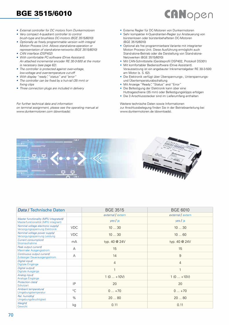
70
BGE 3515/6010
• External controller for DC motors from Dunkermotoren• Very compact 4-quadrant controller to control brush-type and brushless DC-motors (BGE 3515/6010)• Optionally as freely programmable version with integral Motion Process Unit. Allows stand-alone-operation or representation of stand-alone-networks (BGE 3515/6010)• CAN interface (DSP402)• With comfortable PC-software (Drive Assistant). An attached incremental encoder RE 30-3-500 at the motor is necessary (see page 62).• The controller is protected against over-voltage, low-voltage and over-temperature cut-off• With display “ready”, “status” and “error”• The controller can be fixed by a hut-rail (35 mm) or fixing clips• Three connection plugs are included in delivery
For further technical data and information on terminal assignment, please see the operating manual at www.dunkermotoren.com (downloads).
• Externe Regler für DC-Motoren von Dunkermotoren• Sehr kompakter 4-Quandranten-Regler zur Ansteuerung von bürstenlosen oder bürstenbehafteten DC-Motoren (BGE 3515/6010)• Optional als frei programmierbare Variante mit integrierter Motion Process Unit. Diese Ausführung ermöglicht auch Stand-alone-Betrieb oder die Darstellung von Stand-alone- Netzwerken (BGE 3515/6010)• Mit CAN-Schnittstelle (Geräteprofil DSP402, Protokoll DS301)• Mit komfortabler Bediensoftware (Drive Assistant). Voraussetzung ist ein angebauter Inkrementalgeber RE 30-3-500 am Motor (s. S. 62).• Die Elektronik verfügt über Überspannungs-, Unterspannungs- und Übertemperaturabschaltung• Mit Anzeige “Ready”, “Status” and “Error”• Die Befestigung der Elektronik kann über eine Huttrageschiene (35 mm) oder Befestigungsklipps erfolgen• Die 3 Anschlussstecker sind im Lieferumfang enthalten
Weitere technische Daten sowie Informationen zur Anschlussbelegung finden Sie in der Betriebsanleitung bei www.dunkermotoren.de (downloads).
Data / Technische Daten BGE 3515 BGE 6010external / extern external / extern
Master functionality (MPU integrated)/Masterfunktionalität (MPU integriert) yes / ja yes / ja
Nominal voltage electronic supply/Versorgungsspannung Elektronik VDC 10 ... 30 10 ... 30
Nominal voltage power supply/Versorgungsspannung Leistung VDC 10 ... 30 10 ... 60
Current consumption/Stromaufnahme mA typ. 40 @ 24V typ. 40 @ 24V
Peak output current/Maximaler Ausgangsstrom A 15 15
Continuous output current/Zulässiger Dauerausgangsstrom A 14 9
Digital input/Digitale Eingänge 4 4
Digital output/Digitale Ausgänge 1 1
Analog input/Analoge Eingänge 1 (0 ... +10V) 1 (0 ... +10V)
Protection class/Schutzart IP 20 20
Ambient temperature/Umgebungstemperatur °C 0 ... +70 0 ... +70
Rel. humidity/Umgebungsfeuchtigkeit % 20 ... 80 20 ... 80
Weight/Gewicht kg 0.11 0.11
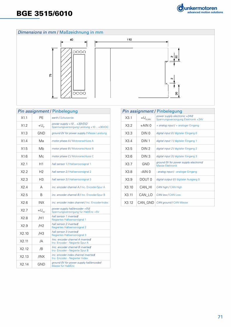
71
BGE 3515/6010
Dimensions in mm / Maßzeichnung in mm
Pin assignment / PinbelegungX1.1 PE earth / Schutzerde
X1.2 +UP
power supply +10 .. +30VDC/Spannungsversorgung Leistung +10 .. +30VDC
X1.3 GND ground 0V for power supply / Masse Leistung
X1.4 Ma motor phase A / Motoranschluss A
X1.5 Mb motor phase B / Motoranschluss B
X1.6 Mc motor phase C / Motoranschluss C
X2.1 H1 hall sensor 1 / Hallsensorsignal 1
X2.2 H2 hall sensor 2 / Hallsensorsignal 2
X2.3 H3 hall sensor 3 / Hallsensorsignal 3
X2.4 A inc. encoder channel A / Inc. Encoder-Spur A
X2.5 B inc. encoder channel B / Inc. Encoder-Spur B
X2.6 INX inc. encoder index channel / Inc. Encoder-Index
X2.7 +U5V
power supply hall/encoder +5V/Spannungsversorgung für Hall/Enc +5V
X2.8 /H1 hall sensor 1 inverted/Negiertes Hallsensorsignal 1
X2.9 /H2 hall sensor 2 inverted/ Negiertes Hallsensorsignal 2
X2.10 /H3 hall sensor 3 inverted/ Negiertes Hallsensorsignal 3
X2.11 /A Iinc. encoder channel A inverted/Inc- Encoder - Negierte Spur A
X2.12 /B Iinc. encoder channel B inverted/Inc- Encoder - Negierte Spur B
X2.13 /INX inc. encoder index channel inverted/ Inc- Encoder - Negierter Index
X2.14 GND ground 0V for power supply hall/encoder/ Masse für Hall/Enc
Pin assignment / PinbelegungX3.1 +U0 24V
power supply electronic +24V/Spannungsversorgung Elektronik +24V
X3.2 +AIN 0 + analog input / + analoger Eingang
X3.3 DIN 0 digital input 0 / digitaler Eingang 0
X3.4 DIN 1 digital input 1 / digitaler Eingang 1
X3.5 DIN 2 digital input 2 / digitaler Eingang 2
X3.6 DIN 3 digital input 3 / digitaler Eingang 3
X3.7 GND ground 0V for power supply electronic/ Masse Elektronik
X3.8 -AIN 0 - analog input / - analoger Eingang
X3.9 DOUT 0 digital output 0 / digitaler Ausgang 0
X3.10 CAN_HI CAN high / CAN High
X3.11 CAN_LO CAN low / CAN Low
X3.12 CAN_GND CAN ground / CAN Masse

72
L
D
ca. 42
øD±1
.00
Motor
45° ±10
30 ±0.50
ca.5
0±0.5
0
2 Cover IP 54 / Schutzhauben IP 54
Accessories / Zubehör
L ±20
Kabel ø 8.2±0.25
3 Connection lead with right-angle connector, 12-pin / Anschlussleitung mit Winkeldose, 12-polig
Pin Color
Ered
F
D green
Mblack
G
B yellow
C blue
J pink
H magenta
A orange
K white
L brown
Connector / Stecker: Binder, Type 99-5630-75-12; Cable / Kabel: Bekonflex-Spezial-X suitable for cable chains / schleppfähig
Length / Länge L (m)
1.5
3
6
10
Protection cover – diameter and length / Hauben-Durchmesser und Länge Dø x L
Motortype / Motortyp Dø x L
GR 42 42 x 15
GR 53 52 x 25
GR 63 63 x 22
GR 80 80 x 22
Connector – assignment for motor with brake or tacho / Steckerbelegung bei Motor mit Bremse bzw. Tacho
Plug 1 / Stecker 1 - Motor
Plug 2 / Stecker 2 + Motor
Motor jointing edge/Attachment dustproofed by gluing a tape / Fügekante Motor/Anbau mit Klebefolie staubdicht umklebt
On request for Tacho Generators, Magnetic Impuls Generators, Incremental Encoders and Brakes. Auf Anfrage für Tachos, Impulsgeber, Inkrementalgeber und Bremsen.
1 Starter Kit / Starter KitIn order to parameterise a drive (motor with integrated controller) or an external controller via PC, a Starter Kit is needed. This provides an interface between the PC and the drive / controller. It must be connected via the USB adapter at a USB port.
The Drive Assistant is a graphic interface which simplifies commissioning and parametrization of the motor.
The Starter Kit contains:- USB adapter with connecting cable- Connection adapter (only for external controllers)- Software “Drive Assistant”
Um einen Antrieb (Motor mit integriertem Regler) oder einem externen Regler mit einem PC zu parametrieren, benötigt man ein Starter Kit. Dieses stellt das Interface vom PC zum Antrieb / Regler dar. Es wird mit dem USB-Adapter an den USB-Port angeschlossen.
Der Drive Assistant ist eine grafische Oberfläche, die Ihnen die einfache Inbetriebnahme und Parametrierung der Antriebe ermöglicht.
Im Starter Kit enthalten sind:- USB-Adapter mit Verbindungskabel- Anschlussadapter (nur für externe Regler)- Software „Drive Assistant“
GR42 2 GR63+RE30 (E90) 4 RE30 TI (E90) 4 RE30 TI 6
GR53 2 GR63+RE30 TI (E90) 4 RE20 5 RE56 TI 6
GR53 SI 3 GR80+RE30 (E90) 4 RE30 5 RS200 7
GR63 2 RE56 5
GR63 SI 3
GR80 2
Power supply / Stromversorgung
USB adapter / USB-Adapter
Software “Drive Assistant”
External controller / Externer Regler Motor / Motor

73
4 Connector for protection covers, 8-pin / Rundsteckverbinder für Schutzhauben, 8-polig
4±1
500±10
5 Connector with cable for RE20/30/56 / Stecker mit Kabel für RE 20/30/56
4±1
500±10
1
3
5
7
9
2
4
6
8
10
6 Connector with cable for RE .. TI / Stecker mit Kabel für RE .. TI
1 2 3 4 5 6 12 13 14 15 16
81.28
76.2
5.08
18.2
15
8.3
2.54
7 Connector with screw terminals for RS 200, 16-pin / Stecker mit Schraubklemmen für RS 200, 16-polig
8 Mounting angle for RS 200 / Montagewinkel für RS 200
Connector / Stecker: DIN 45326 • Accessory for IP-protection / Zubehör für IP-Schutz
Connector / Stecker: Molex, 5-pin Type 5051-M
Connector / Stecker: JST, PHDR-10VS; Leads / Litzen AWG 24
Connector / Stecker: Phoenix Contact, MSTB 2,5/ 16-ST-BD: 1-16, NR 17 57 15 8
Pin Color
1 -
2 red
3 black
4 -
5 grey
6 yellow
7 white
8 green
9 pink
10 brown
Power supply / Stromversorgung
Motor / Motor

© 1
1/20
09
Ges
taltu
ng/S
atz
Di2
Idee
nsch
mie
de
5000
/5.
Prin
ted
in G
erm
any
/M
D
Germany
Sachsen-Anhalt Nord, Berlin, Brandenburg Dunkermotoren GmbHAllmendstraße 11 · 79848 BonndorfTel. (07703) 930-0 · Fax -210/[email protected]
Niedersachsen, Hessen Nord, Westfalen OstIngenieurbüro Heinrich JürgensRoggenhof 5 · 31787 HamelnTel. (05158) 980-98 · Fax [email protected]
Hamburg/Bremen, Schleswig-Holstein, Niedersachsen Nord, Mecklenburg Vorpommern Technisches Büro Kühling/MertenRedder 1 B · 22393 HamburgTel. (040) 5234098 · Fax (040) 5282476www.kuehling-merten.de · [email protected]
Ruhrgebiet Lothar AmbornFasanenstrasse 21b · 45134 Essen-StadtwaldTel. (0201) 4435-00 · Fax [email protected]
Rheinland ATS Antriebstechnik SchloteReisertstrasse 10 · 53773 HennefTel. (02242) 90415-90 · Fax -99 [email protected]
Hessen Antriebstechnik Eberhardt GmbHLandgrabenstrasse 21 · 61118 Bad VilbelTel. (06101) 98168-0 · Fax -10www.antriebstechniken.de/[email protected]
Bayern Nord, Sachsen, Thüringen, Sachsen-Anhalt Süd Christleven GmbHIngenieurbüro für ElektrotechnikPreuschwitzerstr. 38 · 95445 BayreuthTel. (0921) 7413684Fax (0921) 46192www.christleven.de · [email protected]
Bayern Süd Dunkermotoren GmbHAllmendstraße 11 · 79848 BonndorfTel. (07703) 930-0 · Fax -210/[email protected]
Württemberg Technisches Büro SpäthEschenbrünnlestr. 16 · 71065 Sindelfi ngenTel. (07031) 794 34-60 · Fax -70www.spaeth-technik.de · [email protected]
Nordbaden, Rheinland-Pfalz, SaarlandDunkermotoren GmbH Andreas RauPostfach 11 11 13 · 76061 KarlsruheTel. (0721) 830 1021 · Fax (0721) 830 [email protected]
SüdbadenDunkermotoren GmbH Allmendstrasse 11 · 79848 BonndorfTel (07703) 930-0 · Fax (07703) [email protected]
Europe and Overseas
AustriaDunkermotoren Division of Alcatel-LucentStefan Rozic Verkaufsleiter ÖsterreichRaimundstr. 6 · 4053 Haid/ AnsfeldenTel. +43 7229 91054 · Fax +43 7229 [email protected]
Belgium / LuxembourgElmeq B.V.B.A.Industrial Zone Beveren-NoordOnledegoedstraat 79 · 8800 RoeselareTel. +32 51 25 98-11 · Fax -18www.elmeq.be · [email protected]
ChinaDunkermotoren Taicang Co., LtdNo. 9 Factory Premises · 111 North · Dongting RoadTaicang Economy Area · Taicang 215400Jiangsu ProvinceTel. +86 512 8889 8889-0 · Fax +86 512 8889 [email protected]@dunkermotoren.com
Czech RepublikSchmachtl CZ s.r.o.Vestec 185 · 25242 JeseniceTel. +42 02 44 00 15 00 · Fax +42 02 44 91 07 00www.schmachtl.cz · offi [email protected]
DenmarkCompower A/SSmedeholm 13A · 2730 HerlevTel. +45 44 92 66-20 · Fax +45 44 92 66-02www.compower.dk · [email protected]
FinlandWexon OYJuhanilantie 4 · 01740 VantaaTel. +358 9 290 440 · Fax +358 9 290 44100www.wexon.fi · [email protected]
FranceMDP21 Porte du Grand Lyon, Neyron01707 Miribel CédexTel. +33 4 72 01 83 00 · Fax +33 4 72 01 83 09www.mdp.fr · [email protected]
Great BritainDunkermotoren UK, Division of AVTKingfi sher House · Suite 2 · Rownhams LaneNorth Baddesley · Southampton · Hants · SO52 9LPTel. +44 23807 33509 · Fax +44 23807 [email protected]
IsraelAvi Sasson RepresentativesP.O. Box 9270 · 61091 Tel AvivTel. +972 3 5 01 53 22 · Fax +972 3 5 03 19 [email protected]
ItalyDunkermotoren Italia, Division of AVSCorso Sempione, 221 · I-20025 Legnano MI Tel. +39 0331-596165 · Fax +39 0331-455086 [email protected]
KoreaAlcatel Vacuum Technology Korea#315-2, Banwol-Dong, Hwasung-Si, Kyoungki-Do, 445-330Tel. +82 31 206 6277 · Fax +82 31 204 [email protected]
NetherlandsERIKS Aandrijftechniek bvBroeikweg 25 · 2871 RM SchoonhovenTel. +31 182 30 34 56 · Fax +31 182 38 69 20www.eriks-at.nl · [email protected]
NorgeStork ASBrynsveien 100 · 1352 KolsåsTel. +47 67 17 64-00 · Fax -01www.stork.no · [email protected]
PolandP.P.H. WOBIT Witold Ober · ul. Gruszkowa 4 PL 61-474 PoznanTel. +48 61 8350-800 · Fax -704www.wobit.com.pl · [email protected]
SlovakiaSchmachtl SK, s.r.o.Valchárska 3 · 82109 BratislavaTel. +421 2 582756-00 · Fax -01www.schmachtl.sk · offi [email protected]
SpainElmeq S.L.(Gran Via Center) · C/ Vilamarí 50, 3° A y B08015 BarcelonaTel. +34 9422 70 33 · Fax +34 93 432 36 60www.elmeq.es · [email protected]
SwedenDJ Stork Drives ABBox 1037 · Vretenvägen 4 A, Solna SE-172 21 Sundbyberg Tel. +46 8 635 60-00 · Fax -01www.storkdrives.se · [email protected]
Switzerland Dunkermotoren Division of HVTRolf Leitner Verkaufsleiter SchweizPostfach 307 · 8618 Oetwil am See Tel. +41 44 799 17-71 · Fax [email protected]
Turkey Femsan Harmandere Mah. Tasocak Yolu No.8 · 81520 Kurtkoy – Pendik · IstanbulTel. +90 216 482 48 44 · Fax +90 216 482 50 52www.femsan.com · [email protected]
United States of AmericaDunkermotoren – USA
HeadquarterTel. +1 815 261 9100 · Fax +1 815 356 [email protected]
Area US Mid West7105 Virginia Rd, Suite 10 – 14IL 60014 Crystal LakeTel. +1 815 261 9100 · Fax +1 815 356 [email protected]
Area US Southeast1063 Silver Gull Dr.Tega Cay, SC 29708Tel. +1 803 547 8516 · Fax +1 803 547 [email protected]
Area US South Central925 South Main Street, Apt 3439Grapevine, TX 76051Tel. +1 817 488 2827 · Fax +1 817 442 [email protected]
Area US Northeast18 Columbine LaneNY 11754 Kings ParkTel. +1 631 724 [email protected]
Area US Westcoast2715W 180th StreetCA 90504 TorranceTel. +1 310 323 1996 · Fax +1 310 538 [email protected]
Representatives and Distributors / Vertretungen und Vertriebsgesellschaften
Dunkermotoren GmbHAllmendstraße 11 · D-79848 Bonndorf/Schwarzwald
www.dunkermotoren.com · [email protected] · Phone +49 (0) 7703 930-0 · Fax +49 (0) 7703 930-210/212