PERFORMANCE OF A WET-STEAM TURBINE STATOR BLADE … · Department of Steam and Gas turbine,...
11
Paper ID: ETC2017-312 Proceedings of 12th European Conference on Turbomachinery Fluid dynamics & Thermodynamics ETC12, April 3-7, 2017; Stockholm, Sweden 1 PERFORMANCE OF A WET-STEAM TURBINE STATOR BLADE WITH HEATING STEAM INJECTION Gribin V.G. – Tishchenko A.A. – Alexeev R.A. – Gavrilov I.Y. – Khomyakov S.V. – Popov V.V. – Tishchenko V.A. – Sorokin I.Y. Department of Steam and Gas turbine, National Research University "Moscow Power Engineering Institute", Moscow, Russia, E-mail: [email protected] ABSTRACT The results of the experimental studies of wet-steam flow with injection of hot steam from the slot downstream of the turbine flat stator blade cascade have been considered. In the studied profile there is one injection slot on the pressure side surface near the trailing edge. The investigations have been carried out at different initial wetness of the main flow and different injected steam temperatures at the constant pressure of injection. Laser diagnostic system “POLIS” which includes PIV method has been used to analyze the influence of heating steam injection on the characteristics of the liquid phase downstream of the blade trailing edge. It is shown a heating steam injection has an effect on the vector fields of coarse droplets downstream of the blade cascade. At the same time kinetic characteristics of coarse droplets downstream of the stator blades cascade are independent of the temperature of the injected steam. Exit angles of coarse droplets obtained at the different distance from the trailing edge are presented. KEYWORDS STEAM INJECTION, STEAM TURBINE LAST STAGES, WET-STEAM, PIV NOMENCLATURE b chord of the blade h height of blade α 1 deviation angle α s stagger angle Δ tr trailing edge thickness trailing edge thickness to throat ratio δ height of injection slot c d velocity of the liquid particles c s velocity of the steam M 1t theoretical exit Mach number P 0 total pressure upstream studied object Р inj total pressure of the injected steam in the injection chamber P slot static steam pressure in the interblade channel in a section of the injection slot t pitch of the cascade pitch ratio T 0 total temperature upstream the studied object T 2 total temperature of the injecting steam upstream the injection chamber Т inj total temperature of the injected steam in the injection chamber T s (P inj ) saturation temperature at the pressure of the injected steam x coordinate along pitchwise direction y 0 steam initial wetness (upstream studied object) z axis (coordinate) perpendicular to front of the blades cascade α d exit angle of liquid phase particles α Set blade stagger angle α st exit angle of steam phase ΔT 2 deference between total temperature upstream the injection chamber and saturation temperature at the pressure of the injected steam in the injection chamber (superheat) Δα d angular misalignment between steam and liquid phases
Transcript of PERFORMANCE OF A WET-STEAM TURBINE STATOR BLADE … · Department of Steam and Gas turbine,...

Paper ID: ETC2017-312 Proceedings of 12th European Conference on Turbomachinery Fluid dynamics & Thermodynamics ETC12, April 3-7, 2017; Stockholm, Sweden
1
PERFORMANCE OF A WET-STEAM TURBINE STATOR BLADE
WITH HEATING STEAM INJECTION
Gribin V.G. – Tishchenko A.A. – Alexeev R.A. – Gavrilov I.Y. – Khomyakov S.V. –
Popov V.V. – Tishchenko V.A. – Sorokin I.Y.
Department of Steam and Gas turbine, National Research University "Moscow Power Engineering
Institute", Moscow, Russia, E-mail: [email protected]
ABSTRACT
The results of the experimental studies of wet-steam flow with injection of hot steam from
the slot downstream of the turbine flat stator blade cascade have been considered. In the
studied profile there is one injection slot on the pressure side surface near the trailing edge.
The investigations have been carried out at different initial wetness of the main flow and
different injected steam temperatures at the constant pressure of injection. Laser diagnostic
system “POLIS” which includes PIV method has been used to analyze the influence of heating
steam injection on the characteristics of the liquid phase downstream of the blade trailing
edge.
It is shown a heating steam injection has an effect on the vector fields of coarse droplets
downstream of the blade cascade. At the same time kinetic characteristics of coarse droplets
downstream of the stator blades cascade are independent of the temperature of the injected
steam. Exit angles of coarse droplets obtained at the different distance from the trailing edge
are presented.
KEYWORDS
STEAM INJECTION, STEAM TURBINE LAST STAGES, WET-STEAM, PIV
NOMENCLATURE
b chord of the blade
h height of blade
α1 deviation angle
αs stagger angle
Δtr trailing edge thickness
𝛥𝑡𝑟 trailing edge thickness to throat ratio
δ height of injection slot
cd velocity of the liquid particles
cs velocity of the steam
M1t theoretical exit Mach number
P0 total pressure upstream studied object
Рinj total pressure of the injected steam in
the injection chamber
Pslot static steam pressure in the interblade
channel in a section of the injection slot
t pitch of the cascade
𝑡 pitch ratio
T0 total temperature upstream the studied
object
T2 total temperature of the injecting
steam upstream the injection chamber
Тinj total temperature of the injected steam
in the injection chamber
Ts(Pinj) saturation temperature at the
pressure of the injected steam
x coordinate along pitchwise direction
y0 steam initial wetness (upstream
studied object)
z axis (coordinate) perpendicular to
front of the blades cascade
αd exit angle of liquid phase particles
αSet blade stagger angle
αst exit angle of steam phase
ΔT2 deference between total temperature
upstream the injection chamber and saturation
temperature at the pressure of the injected
steam in the injection chamber (superheat)
Δαd angular misalignment between steam
and liquid phases

2
εinj relative pressure of the injected steam
ν slip coefficient
Reb Reynolds number by chord
𝑔 mass flow rate in the slot to mass flow
rate in the channel ratio
𝑐 velocity in the slot to the flow velocity
ratio
hinj enthalpy of the injected steam in the
injection chamber
h2 enthalpy of the injecting steam
upstream the injection chamber
Ging mass flow of injected steam
Fs heated surface
INTRODUCTION
At the moment the problem of erosion of turbine blades which operate in wet-steam area is quite
nowadays. This problem is still unsolved and is one of the main issues which manufacturers of wet
steam turbines face. The presence of erosion-hazard due to coarse droplets leads to damage of rotor
and stator blades surfaces. It reduces the efficiency and reliability of steam turbines.
The processes of erosion determine the value of maximum wetness downstream of the last stage
of steam turbine according to Filippov and Korobkov (1973). The main source of the erosion-
hazard droplets in the flow paths of steam turbine is the process of water film breakup from the
surfaces of inter-blade channels which formed by deposition of liquid particles. This process takes
place in low pressure cylinders of steam turbines according to Filippov and Povarov (1980). The
process of deposition of water droplets on the blade surface depends on their diameter and density
of working fluid (Filippov et al. (2012)).
In the literature a lot of publications and papers are dedicated to water film removal from the
blade surfaces (Gribin et al. (2010), Sakamoto et al. (1992), Tanuma and Sakamoto (1991)). But as
shown by recent investigations (Gribin et al. (2016) and Hoznedl et al. (2012)) the number of
removed water is strongly dependent on the operational parameters of turbine. Even small changes
in turbine stage operational conditions reduce the efficiency of this method. It should be noted that
together with removed moisture a portion of steam is removed too. However, this leads to
nonrecoverable losses of turbine power.
In the previous part of this study (Gribin et al. (2014)), it was shown how the injected steam
pressure influences on the characteristics of liquid phase. This paper presents the results of an
experimental study of the effect of the temperature of injected steam on the main characteristics of
the erosion-hazard droplets in the isolated flat stator blades cascade.
THE EXPERIMENTAL FACILITY AND THE OBJECT OF THE INVESTIGATION
The investigations were performed on the experimental facility Wet Steam Circuit (WSC) (see
Fig. 1) in the turbine laboratory of the Moscow Power Engineering Institute (MPEI). This
experimental facility is used to study the flows of superheated, saturated and wet steam in the
different elements of flow parts of steam turbines.
Figure 1: The experimental facility Wet Steam Circuit (WSC)

3
A schematic flow diagram of WSC is shown in Fig. 2. The saturated steam form the extraction
of the steam turbine goes to the first wetting stage (1), which is used to decrease the steam
temperature by injection of feed water (coming from the feed water header (6)) into the flow. After
the first wetting stage working fluid enters the steam header (2). A part of the steam comes to the
receiver tank (3) from the header (2). In this steam pipeline is located the second wetting stage (9)
which is used to reduce steam temperature to the saturated state. The third wetting stage (4) is a
block of the feed water jets. These jets (4) are used to produce polydisperse two-phase medium
upstream of the studied object (5). The working medium passes the studied object mounted in the
removable working part (5) and comes to the condenser (7). Then condensate returns into the power
plant cycle. Supply of injected steam (8) is realized by the extraction from the header (2).
Figure 2: Schematic diagram of WSC
To investigate the influence of the injection steam temperature on the dynamics of the liquid
phase downstream of the isolated stator blades cascade, the POLIS laser diagnostic system was
used. In this system the PIV (particle image velocity) method has been used. This method allows to
determine a two-component instantaneous velocity vector fields on a regular grid (velocity
measuring range: 0.001 – 1000 m/s; error of no more than 1 %). The methodology of laser
diagnostic system adapted to the polydisperse wet-steam flow. This is successfully applied in
Gavrilov et al. (2014), Sorokin et al. (2016), Filippov et al. (2014), Gribin et al. (2016) and Gribin
et al. (2014). The steam velocity (cs) was determined by a simulation using the Ansys Fluent 14
incorporating wet-steam model. The results of this model are compared with experimental data in
Filippov et al. (2014).
In this paper, the averaged characteristics of droplet’s streams downstream of the blade cascade
were determined (the example of the velocity vector field is given in Fig. 3). They were obtained by
means of statistic processing of instantaneous velocity vector fields set. In Fig. 3 the coordinate
axes (z, x) are marked. The liquid phase parameters have been obtained along the lines downstream
of the blade cascade shown in the Fig. 3.

4
Figure 3: Averaged velocity vector field of liquid phase downstream the blade cascade
The studied object is a flat cascade of hollow stator blades with a slot for steam injection at the
pressure surface of the blade (see Fig. 4). Data about cascade geometry are listed in table 1. The
cascade was installed into the working part that is shown in Fig. 4. The investigation condition was
described in table 2. Pressure was measured by vacuum gauge (±0.15 full scale output).
Temperature was measured by PT100 platinum resistance thermometer. The total pressure Рinj and
the temperature Тinj of the injected steam were measured in the injection chamber. The WSC facility
includes a surface heat exchanger (3) in order to change the temperature of the injected steam. In
this way, it is possible to vary the injected steam temperature upstream of injection chamber in the
range of ΔT2 = 0 – 100 K. The superheat of the injected steam ΔT2 was determined as:
ΔT2 = T2 – Ts(Рinj). (1)
The relative pressure of the injected steam at all conditions remains constant and corresponds to
εinj = 0.8. The relative pressure of the injected steam εinj was determined as:
εinj = Pslot / Рinj. (2)
Pslot was measured in the injection chamber when steam wasn’t injected (εinj =1). The mass flow
rate of the injected steam was controlled by a mass flow meter 4.
Figure 4: The studied object (а) scheme of working part (b)
5
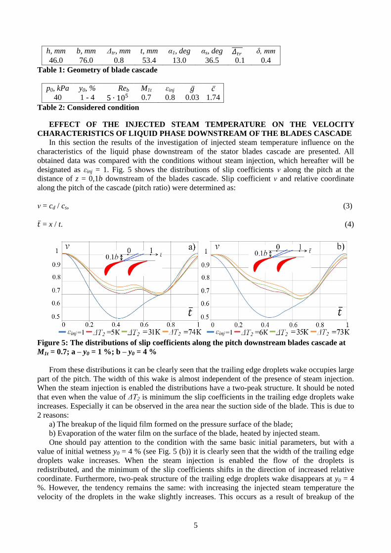
h, mm b, mm Δtr, mm t, mm α1, deg αs, deg 𝛥𝑡𝑟 δ, mm
46.0 76.0 0.8 53.4 13.0 36.5 0.1 0.4
Table 1: Geometry of blade cascade
p0, kPa y0, % Reb M1t εinj 𝑔 𝑐 40 1 - 4 5 ∙ 105 0.7 0.8 0.03 1.74
Table 2: Considered condition
EFFECT OF THE INJECTED STEAM TEMPERATURE ON THE VELOCITY
CHARACTERISTICS OF LIQUID PHASE DOWNSTREAM OF THE BLADES CASCADE
In this section the results of the investigation of injected steam temperature influence on the
characteristics of the liquid phase downstream of the stator blades cascade are presented. All
obtained data was compared with the conditions without steam injection, which hereafter will be
designated as εinj = 1. Fig. 5 shows the distributions of slip coefficients ν along the pitch at the
distance of z = 0,1b downstream of the blades cascade. Slip coefficient ν and relative coordinate
along the pitch of the cascade (pitch ratio) were determined as:
ν = cd / cs, (3)
𝑡 = x / t. (4)
Figure 5: The distributions of slip coefficients along the pitch downstream blades cascade at
M1t = 0.7; a – y0 = 1 %; b – y0 = 4 %
From these distributions it can be clearly seen that the trailing edge droplets wake occupies large
part of the pitch. The width of this wake is almost independent of the presence of steam injection.
When the steam injection is enabled the distributions have a two-peak structure. It should be noted
that even when the value of ΔT2 is minimum the slip coefficients in the trailing edge droplets wake
increases. Especially it can be observed in the area near the suction side of the blade. This is due to
2 reasons:
a) The breakup of the liquid film formed on the pressure surface of the blade;
b) Evaporation of the water film on the surface of the blade, heated by injected steam.
One should pay attention to the condition with the same basic initial parameters, but with a
value of initial wetness y0 = 4 % (see Fig. 5 (b)) it is clearly seen that the width of the trailing edge
droplets wake increases. When the steam injection is enabled the flow of the droplets is
redistributed, and the minimum of the slip coefficients shifts in the direction of increased relative
coordinate. Furthermore, two-peak structure of the trailing edge droplets wake disappears at y0 = 4
%. However, the tendency remains the same: with increasing the injected steam temperature the
velocity of the droplets in the wake slightly increases. This occurs as a result of breakup of the
6
liquid film which separates from the pressure surface of the blade, and its evaporating mostly from
the suction surface of the blade.
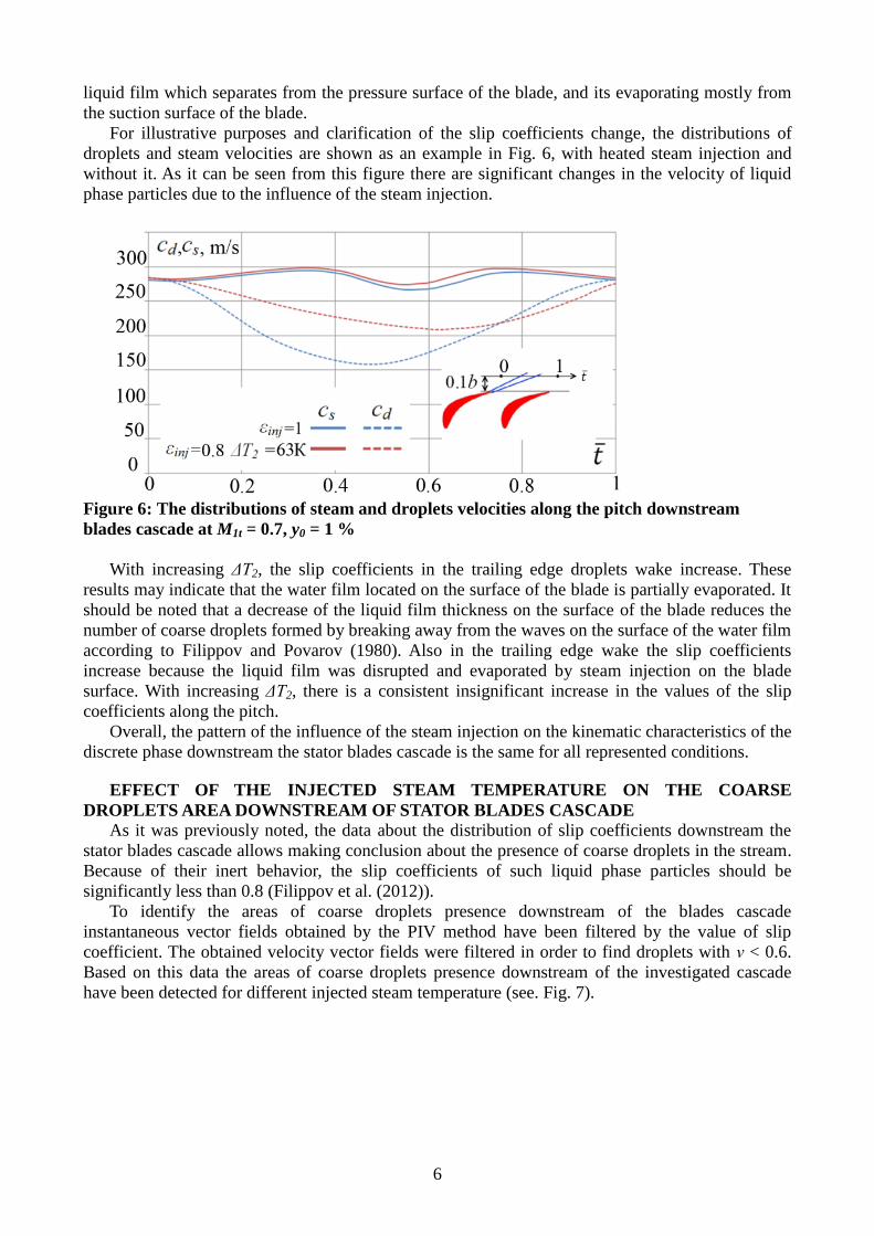
For illustrative purposes and clarification of the slip coefficients change, the distributions of
droplets and steam velocities are shown as an example in Fig. 6, with heated steam injection and
without it. As it can be seen from this figure there are significant changes in the velocity of liquid
phase particles due to the influence of the steam injection.
Figure 6: The distributions of steam and droplets velocities along the pitch downstream
blades cascade at M1t = 0.7, y0 = 1 %
With increasing ΔT2, the slip coefficients in the trailing edge droplets wake increase. These
results may indicate that the water film located on the surface of the blade is partially evaporated. It
should be noted that a decrease of the liquid film thickness on the surface of the blade reduces the
number of coarse droplets formed by breaking away from the waves on the surface of the water film
according to Filippov and Povarov (1980). Also in the trailing edge wake the slip coefficients
increase because the liquid film was disrupted and evaporated by steam injection on the blade
surface. With increasing ΔT2, there is a consistent insignificant increase in the values of the slip
coefficients along the pitch.
Overall, the pattern of the influence of the steam injection on the kinematic characteristics of the
discrete phase downstream the stator blades cascade is the same for all represented conditions.
EFFECT OF THE INJECTED STEAM TEMPERATURE ON THE COARSE
DROPLETS AREA DOWNSTREAM OF STATOR BLADES CASCADE
As it was previously noted, the data about the distribution of slip coefficients downstream the
stator blades cascade allows making conclusion about the presence of coarse droplets in the stream.
Because of their inert behavior, the slip coefficients of such liquid phase particles should be
significantly less than 0.8 (Filippov et al. (2012)).
To identify the areas of coarse droplets presence downstream of the blades cascade
instantaneous vector fields obtained by the PIV method have been filtered by the value of slip
coefficient. The obtained velocity vector fields were filtered in order to find droplets with ν < 0.6.
Based on this data the areas of coarse droplets presence downstream of the investigated cascade
have been detected for different injected steam temperature (see. Fig. 7).
7
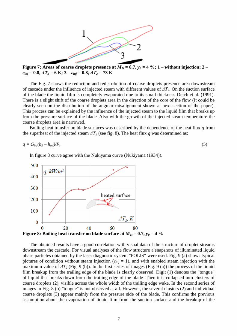
Figure 7: Areas of coarse droplets presence at M1t = 0.7, y0 = 4 %; 1 – without injection; 2 –
εinj = 0.8, ΔT2 = 6 К; 3 – εinj = 0.8, ΔT2 = 73 К
The Fig. 7 shows the reduction and redistribution of coarse droplets presence area downstream
of cascade under the influence of injected steam with different values of ΔT2. On the suction surface
of the blade the liquid film is completely evaporated due to its small thickness Deich et al. (1991).
There is a slight shift of the coarse droplets area in the direction of the core of the flow (It could be
clearly seen on the distribution of the angular misalignment shown at next section of the paper).
This process can be explained by the influence of the injected steam to the liquid film that breaks up
from the pressure surface of the blade. Also with the growth of the injected steam temperature the
coarse droplets area is narrowed.
Boiling heat transfer on blade surfaces was described by the dependence of the heat flux q from
the superheat of the injected steam ΔT2 (see fig. 8). The heat flux q was determined as:
q = Ginj(h2 – hinj)/Fs (5)
In figure 8 curve agree with the Nukiyama curve (Nukiyama (1934)).
Figure 8: Boiling heat transfer on blade surface at M1t = 0.7, y0 = 4 %
The obtained results have a good correlation with visual data of the structure of droplet streams
downstream the cascade. For visual analyses of the flow structure a snapshots of illuminated liquid
phase particles obtained by the laser diagnostic system "POLIS" were used. Fig. 9 (a) shows typical
pictures of condition without steam injection (εinj = 1), and with enabled steam injection with the
maximum value of ΔT2 (Fig. 9 (b)). In the first series of images (Fig. 9 (a)) the process of the liquid
film breakup from the trailing edge of the blade is clearly observed. Digit (1) denotes the "tongue"
of liquid that breaks down from the trailing edge of the blade. Then it is collapsed into clusters of
coarse droplets (2), visible across the whole width of the trailing edge wake. In the second series of
images in Fig. 8 (b) "tongue" is not observed at all. However, the several clusters (2) and individual
coarse droplets (3) appear mainly from the pressure side of the blade. This confirms the previous
assumption about the evaporation of liquid film from the suction surface and the breakup of the

8
water film from the pressure surface of the blade. This confirms the effectiveness of the steam
injection from the point of view of reduction of the average size of coarse droplets.
Figure 9: Visual structure of the wet steam flow downstream the cascade at M1t = 0.7, y0 = 4
%; a – εinj = 1; b – εinj = 0.8, ΔT2 = 73 К
EFFECT OF THE INJECTED STEAM TEMPERATURE ON THE EXIT ANGLE OF
THE LIQUID PHASE
The liquid phase inlet angle of the rotor blades is an important factor affecting the process of
erosion wear of the steam turbine last stages operated in wet-steam area. The fine droplets move
along the streamlines of the main flow. But the coarse droplets move with angular misalignment Δα
determined by the formula:
Δα = αd – αst. (5)
The distribution of angular misalignment can be used as an indirect criterion to determine the
effectiveness of the investigated method on minimization of rotor blades erosion damage. Fig. 10
shows this distribution for one studied condition (M1t = 0.7, y0 = 1 %), obtained at a distance of 0.1b
downstream of the stator blades cascade.
As it can be seen, the value of Δα practically does not depend on the value of ΔT2. The data
obtained with other initial parameters of the flow will be presented by the typical conditions (εinj = 1
and εinj = 0.8 with the maximum value of ΔT2).

9
Figure 10: Angular misalignment distributions along the pitch downstream the cascade at M1t
= 0.7, y0 = 1 %; а – on distance 0.1b, b – on distance 0.15b
The highest values of Δα were observed in the trailing edge wake due to the maximum
concentration of coarse droplets in this area. By enabling the steam injection (εinj = 0.8) Δα reduces
from the velocity side of the blade, and also in the center of the trailing edge wake due to
evaporation and liquid film breakup processes. But from the pressure side of the blade there is a
small growth in Δα, due to the restructuring of the flow at the place of injection slot and destruction
of the liquid film by the steam injection. Fig. 10 (b) shows the angular misalignment distributions
obtained at a distance of 0.15b.
As it can be seen, the value of Δα from the pressure side (𝑡 = 0.8 – 1) decreases, and the center of
trailing edge wake (𝑡 = 0.3 – 0.8) remains the same as at a distance of 0.1b. The steam injection
affects on the droplets in the trailing edge wake by the following way:
1) In the area near the suction side of the blade (𝑡 = 0.2 – 0.4) Δα reduces due to the liquid film
evaporation.
2) In the center of the trailing edge wake Δα reduces due to disruption of liquid film by steam
injection.
3) In the area from the pressure side of the blade Δα increases due to the effect of steam
injection on the width of the trailing edge wake.
The steam injection leads to decrease of coarse droplets diameters, but trailing edge wake near
front of the cascade (0.1b) becomes wider. But in the downstream direction (0.15b) value of Δα
becomes similar to the condition without steam injection due to the reduction of droplets diameters.
The distributions are obtained with the same basic initial parameters at initial wetness of y0 = 4 %,
which approximately corresponds to previously obtained data (see Fig. 11).
Figure 11: Angular misalignment distributions along the pitch downstream the cascade at M1t
= 0.7, y0 = 4 %

10
CONCLUSIONS
1. The steam injection increases the slip coefficients in a trailing edge wake of the stator blade.
This process indicates the reduction of coarse droplet diameters. The increase of the injected steam
temperature provides insignificant increase in slip coefficients.
2. The steam injection has a significant influence on the kinematic characteristics of the liquid
phase. The influence of the steam injection on the kinematic characteristics of the steam phase is
negligible.
3. Enabling of steam injection leads to significant reduction of coarse droplets area. The
increase of the injected steam temperature provides to insignificant reduction of this area.
4. Visual analysis of the flow structure shows the liquid film was disrupted by the steam
injection on the blade.
5. Analysis of angular misalignment distributions shows insignificant increase in the trailing
edge wake width. But the values of angular misalignment decrease.
The overall results of experimental data show that the steam injection leads to reduction of the
liquid droplets diameters in the trailing edge wake area. Besides the increase of the injected steam
temperature does not have a significant influence on the efficiency of this method. So this method
of minimization of the rotor blades erosion damage can be used as the main system of erosion wear
reduction.
ACKNOWLEDGEMENTS
This study was supported by Russian Foundation for Basic Research (project N 15-08-03592).
REFERENCES
Filippov G. A. and Korobkov V.V. (1973) Impact of the blade erosion on the value of the limit
humidity behind the last stage. Thermal Engineering, Vol. 20, No. 12, pp. 14 – 18
Filippov G.A. and Povarov O. A. (1980) Separaciya vlagi v turbinah AES [Separation of
wetness in APP turbines]. Energiya, Moscow, Russia
Filippov G.A., Gribin V.G., Tishchenko A.A. and Lisyanskii A.S. (2012) The effect of wetness
on steam turbine efficiency. J. Izvestija Rossijskoy Akademii Nauk: Energetika [Proceedings of the
Russian Academy of Sciences: Energy]. No.6, pp. 96-107
Gribin V.G., Korshunov B.A. and Tishchenko A.A. (2010) A Study of Interchannel Separation
of Moisture in Nozzle Cascades of Turbines. Thermal Engineering, Vol. 57, No. 9, pp. 746–750
Sakamoto T., Nagao S. and Tanuma, T. (1992) Investigation of wet steam flow for steam turbine
repowering. Proc. Int. Joint Power Generation Conference, Paper 10/18-22/92, pp. 33-40
Tanuma, T. and Sakamoto, T. (1991) The removal of water from steam turbine stationary blades
by suction slots. Proceedings of the IMechE, Part C: Journal of Mechanical Engineering Science,
Paper 423/022, pp. 179-189
Gribin V.G., Tishchenko A.A., Gavrilov I.Yu., Popov V.V., Sorokin I.Yu., Tishchenko V.A.,
Khomyakov S.V. (2016) Experimental Study of Intrachannel Separation in a Flat Nozzle Turbine
Blade Assembly With Wet Stream Flow. Power Technology and Engineering, Volume 50, Issue 2,
pp. 180–187
Michal Hoznedl, Ladislav Tajc, Lukas Bednar (2012) Separation of the liquid phase from the
stator blades of the last stage of a steam turbine. Baumann Centenary Conference BCC-2012-19
10-11, Cambridge, England
Vladimir Gribin, Alexandr Tishchenko, Victor Tishchenko, Ilya Gavrilov, Sergey Khomiakov,
Vitaliy Popov, Alexandr Lisyanskiy, Alexandr Nekrasov, Vladimir Nazarov, Konstantin Usachev
(2014) An experimental study of influence of the steam injection on the profile surface on the
turbine nozzle cascade performance. Proceedings of ASME Turbo Expo 2014, GT2014-27118,
Dusseldorf, Germany
Gavrilov I. Yu., Popov V. V., Sorokin I. Yu., Tishchenko V. A., Khomyakov S. V. (2014) A
Contactless Technique for Determining the Average Sizes of Erosion-Hazardous Droplets in
Polydisperse Wet Steam Flow. Thermal Engineering, Vol. 61, No. 8, pp. 577–584

11
Ivan Sorokin, Vladimir Gribin, Ilya Gavrilov, Aleksandr Tishchenko, Victor Tishchenko, Vitaliy
Popov, Sergey Khomyakov, Roman Alexeev (2016) Features of liquid phase movement in the inter-
blade channel of nozzle blade cascade. Proceedings of Wet Steam Conference, pp. 201-211, Prague,
Czech Republic
Gennadiy Filippov, Vladimir Gribin, Aleksandr Tischenko, Ilya Gavrilov, Victor Tishchenko
(2014) Experimental studies of polydispersed wet steam flows in a turbine blade cascade.
Proceedings of the IMechE, Part A: Journal of Power and Energy. Vol. 228, No. 2, pp. 168-177.
Deich M.E., Povarov O. A., Troitskiy A.N., Fedorov A.S. (1991) The structure and
characteristics of the film flows in the nozzle cascades of turbines. J. Izvestija Akademii Nauk
USSR: Energetika i transport [Proceedings of the USSR Academy of Sciences: Energy and
transport]. No.2, pp. 110-122
S. Nukiyama (1934) Maximum and minimum values of heat q transmitted from metal to
boiling water under atmospheric pressure. J. Soc. Mech. Eng. Jpn., No. 37, pp. 367 – 374