Performance of a 2D-3D Image Registration System using (Lossy) Compressed X … · ·...
11
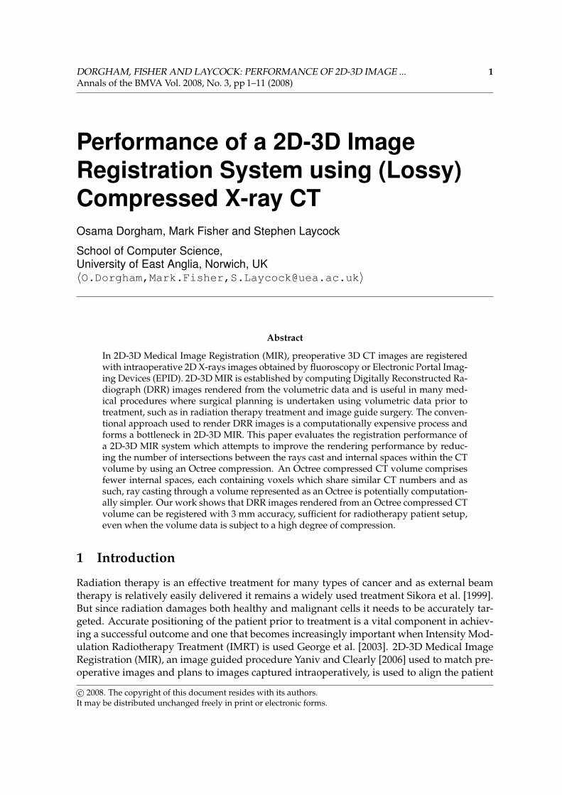
DORGHAM, FISHER AND LAYCOCK: PERFORMANCE OF 2D-3D IMAGE ... 1 Annals of the BMVA Vol. 2008, No. 3, pp1–11 (2008) Performance of a 2D-3D Image Registration System using (Lossy) Compressed X-ray CT Osama Dorgham, Mark Fisher and Stephen Laycock School of Computer Science, University of East Anglia, Norwich, UK hO.Dorgham,Mark.Fisher,[email protected]i Abstract In 2D-3D Medical Image Registration (MIR), preoperative 3D CT images are registered with intraoperative 2D X-rays images obtained by fluoroscopy or Electronic Portal Imag- ing Devices (EPID). 2D-3D MIR is established by computing Digitally Reconstructed Ra- diograph (DRR) images rendered from the volumetric data and is useful in many med- ical procedures where surgical planning is undertaken using volumetric data prior to treatment, such as in radiation therapy treatment and image guide surgery. The conven- tional approach used to render DRR images is a computationally expensive process and forms a bottleneck in 2D-3D MIR. This paper evaluates the registration performance of a 2D-3D MIR system which attempts to improve the rendering performance by reduc- ing the number of intersections between the rays cast and internal spaces within the CT volume by using an Octree compression. An Octree compressed CT volume comprises fewer internal spaces, each containing voxels which share similar CT numbers and as such, ray casting through a volume represented as an Octree is potentially computation- ally simpler. Our work shows that DRR images rendered from an Octree compressed CT volume can be registered with 3 mm accuracy, sufficient for radiotherapy patient setup, even when the volume data is subject to a high degree of compression. 1 Introduction Radiation therapy is an effective treatment for many types of cancer and as external beam therapy is relatively easily delivered it remains a widely used treatment Sikora et al. [1999]. But since radiation damages both healthy and malignant cells it needs to be accurately tar- geted. Accurate positioning of the patient prior to treatment is a vital component in achiev- ing a successful outcome and one that becomes increasingly important when Intensity Mod- ulation Radiotherapy Treatment (IMRT) is used George et al. [2003]. 2D-3D Medical Image Registration (MIR), an image guided procedure Yaniv and Clearly [2006] used to match pre- operative images and plans to images captured intraoperatively, is used to align the patient c 2008. The copyright of this document resides with its authors. It may be distributed unchanged freely in print or electronic forms.
Transcript of Performance of a 2D-3D Image Registration System using (Lossy) Compressed X … · ·...
DORGHAM, FISHER AND LAYCOCK: PERFORMANCE OF 2D-3D IMAGE ... 1Annals of the BMVA Vol. 2008, No. 3, pp 1–11 (2008)
Performance of a 2D-3D ImageRegistration System using (Lossy)Compressed X-ray CTOsama Dorgham, Mark Fisher and Stephen Laycock
School of Computer Science,University of East Anglia, Norwich, UK〈O.Dorgham,Mark.Fisher,[email protected]〉
Abstract
In 2D-3D Medical Image Registration (MIR), preoperative 3D CT images are registeredwith intraoperative 2D X-rays images obtained by fluoroscopy or Electronic Portal Imag-ing Devices (EPID). 2D-3D MIR is established by computing Digitally Reconstructed Ra-diograph (DRR) images rendered from the volumetric data and is useful in many med-ical procedures where surgical planning is undertaken using volumetric data prior totreatment, such as in radiation therapy treatment and image guide surgery. The conven-tional approach used to render DRR images is a computationally expensive process andforms a bottleneck in 2D-3D MIR. This paper evaluates the registration performance ofa 2D-3D MIR system which attempts to improve the rendering performance by reduc-ing the number of intersections between the rays cast and internal spaces within the CTvolume by using an Octree compression. An Octree compressed CT volume comprisesfewer internal spaces, each containing voxels which share similar CT numbers and assuch, ray casting through a volume represented as an Octree is potentially computation-ally simpler. Our work shows that DRR images rendered from an Octree compressed CTvolume can be registered with 3 mm accuracy, sufficient for radiotherapy patient setup,even when the volume data is subject to a high degree of compression.
1 Introduction
Radiation therapy is an effective treatment for many types of cancer and as external beamtherapy is relatively easily delivered it remains a widely used treatment Sikora et al. [1999].But since radiation damages both healthy and malignant cells it needs to be accurately tar-geted. Accurate positioning of the patient prior to treatment is a vital component in achiev-ing a successful outcome and one that becomes increasingly important when Intensity Mod-ulation Radiotherapy Treatment (IMRT) is used George et al. [2003]. 2D-3D Medical ImageRegistration (MIR), an image guided procedure Yaniv and Clearly [2006] used to match pre-operative images and plans to images captured intraoperatively, is used to align the patient
c© 2008. The copyright of this document resides with its authors.It may be distributed unchanged freely in print or electronic forms.
2 DORGHAM, FISHER AND LAYCOCK: PERFORMANCE OF 2D-3D IMAGE ...Annals of the BMVA Vol. 2008, No. 3, pp 1–11 (2008)
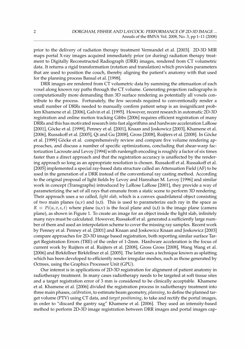
prior to the delivery of radiation therapy treatment Vermandel et al. [2003]. 2D-3D MIRmaps portal X-ray images acquired immediately prior (or during) radiation therapy treat-ment to Digitally Reconstructed Radiograph (DRR) images, rendered from CT volumetricdata. It returns a rigid transformation (rotation and translation) which provides parametersthat are used to position the couch, thereby aligning the patient’s anatomy with that usedfor the planning process Bansal et al. [1998].
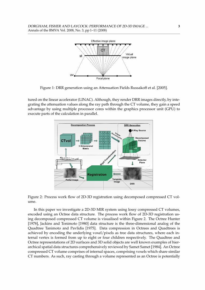
DRR images are rendered from CT volumetric data by summing the attenuation of eachvoxel along known ray paths through the CT volume. Generating projection radiographs iscomputationally more demanding than 3D surface rendering as potentially all voxels con-tribute to the process. Fortunately, the few seconds required to conventionally render asmall number of DRRs needed to manually confirm patient setup is an insignificant prob-lem Khamene et al. [2006], Galvin et al. [1995]. However, recent research in automatic 2D-3Dregistration and online motion tracking Gibbs [2006] requires efficient registration of manyDRRs and this has motivated research into fast algorithms and hardware acceleration LaRose[2001], Göcke et al. [1999], Penney et al. [2001], Knaan and Joskowicz [2003], Khamene et al.[2006], Russakoff et al. [2005], Qi and Gu [2008], Gross [2008], Ruijters et al. [2008]. In Göckeet al. [1999] Göcke et al. comprehensively review and compare five volume rendering ap-proaches, and discuss a number of specific optimizations, concluding that shear-warp fac-torization Lacroute and Levoy [1994] with runlength encoding is roughly a factor of six timesfaster than a direct approach and that the registration accuracy is unaffected by the render-ing approach so long as an appropriate resolution is chosen. Russakoff et al. Russakoff et al.[2005] implemented a special ray-based data structure called an Attenuation Field (AF) to beused in the generation of a DRR instead of the conventional ray casting method. Accordingto the original proposal of light fields by Levoy and Hanrahan M. Levoy [1996] and similarwork in concept (Transgraphs) introduced by LaRose LaRose [2001], they provide a way ofparameterizing the set of all rays that emanate from a static scene to perform 3D rendering.Their approach uses a so called, light slab, which is a convex quadrilateral object consistingof two main planes (u,v) and (s,t). This is used to parameterize each ray in the space asR ≡ Pi(u, v, s, t) where plane (u,v) is the focal plane and (s,t) is the image plane (cameraplane), as shown in Figure 1. To create an image for an object inside the light slab, infinitelymany rays must be calculated. However, Russakoff et al. generated a sufficiently large num-ber of them and used an interpolation scheme to cover the missing ray samples. Recent workby Penney et al. Penney et al. [2001] and Knaan and Joskowicz Knaan and Joskowicz [2003]compare approaches for 2D-3D image based registration, both reporting similar surface Tar-get Registration Errors (TRE) of the order of 1-2mm. Hardware acceleration is the focus ofcurrent work by Ruijters et al. Ruijters et al. [2008], Gross Gross [2008], Wang Wang et al.[2006] and Birkfellner Birkfellner et al. [2005]. The latter uses a technique known as splattingwhich has been developed to efficiently render irregular meshes, such as those generated byOctrees, using the Graphics Processor Unit (GPU).
Our interest is in applications of 2D-3D registration for alignment of patient anatomy inradiotherapy treatment. In many cases radiotherapy needs to be targeted at soft tissue sitesand a target registration error of 3 mm is considered to be clinically acceptable. Khameneet al. Khamene et al. [2006] divided the registration process in radiotherapy treatment intothree main phases, calibration, to estimate beam geometry, planning, to define the planned tar-get volume (PTV) using CT data, and target positioning, to take and rectify the portal images,in order to “discard the gantry sag” Khamene et al. [2006]. They used an intensity-basedmethod to perform 2D-3D image registration between DRR images and portal images cap-
DORGHAM, FISHER AND LAYCOCK: PERFORMANCE OF 2D-3D IMAGE ... 3Annals of the BMVA Vol. 2008, No. 3, pp 1–11 (2008)
Figure 1: DRR generation using an Attenuation Fields Russakoff et al. [2005].
tured on the linear accelerator (LINAC). Although, they render DRR images directly, by inte-grating the attenuation values along the ray path through the CT volume, they gain a speedadvantage by using multiple processor cores within the graphics processor unit (GPU) toexecute parts of the calculation in parallel.
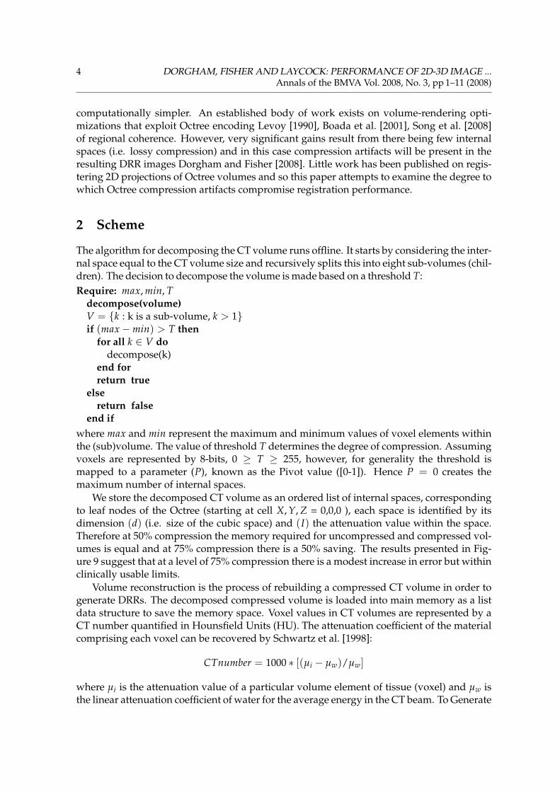
Figure 2: Process work flow of 2D-3D registration using decomposed compressed CT vol-ume.
In this paper we investigate a 2D-3D MIR system using lossy compressed CT volumes,encoded using an Octree data structure. The process work flow of 2D-3D registration us-ing decomposed compressed CT volume is visualised within Figure 2. The Octree Hunter[1978], Jackins and Tonimoto [1980] data structure is the three-dimensional analog of theQuadtree Tanimoto and Pavlidis [1975]. Data compression in Octrees and Quadtrees isachieved by encoding the underlying voxel/pixels as tree data structures, where each in-ternal vertex is formed from up to eight or four children respectively. The Quadtree andOctree representations of 2D surfaces and 3D solid objects are well known examples of hier-archical spatial data structures comprehensively reviewed by Samet Samet [1984]. An Octreecompressed CT volume comprises of internal spaces, comprising voxels which share similarCT numbers. As such, ray casting through a volume represented as an Octree is potentially
4 DORGHAM, FISHER AND LAYCOCK: PERFORMANCE OF 2D-3D IMAGE ...Annals of the BMVA Vol. 2008, No. 3, pp 1–11 (2008)
computationally simpler. An established body of work exists on volume-rendering opti-mizations that exploit Octree encoding Levoy [1990], Boada et al. [2001], Song et al. [2008]of regional coherence. However, very significant gains result from there being few internalspaces (i.e. lossy compression) and in this case compression artifacts will be present in theresulting DRR images Dorgham and Fisher [2008]. Little work has been published on regis-tering 2D projections of Octree volumes and so this paper attempts to examine the degree towhich Octree compression artifacts compromise registration performance.
2 Scheme
The algorithm for decomposing the CT volume runs offline. It starts by considering the inter-nal space equal to the CT volume size and recursively splits this into eight sub-volumes (chil-dren). The decision to decompose the volume is made based on a threshold T:Require: max, min, T
decompose(volume)V = {k : k is a sub-volume, k > 1}if (max−min) > T then
for all k ∈ V dodecompose(k)
end forreturn true
elsereturn false
end ifwhere max and min represent the maximum and minimum values of voxel elements withinthe (sub)volume. The value of threshold T determines the degree of compression. Assumingvoxels are represented by 8-bits, 0 ≥ T ≥ 255, however, for generality the threshold ismapped to a parameter (P), known as the Pivot value ([0-1]). Hence P = 0 creates themaximum number of internal spaces.
We store the decomposed CT volume as an ordered list of internal spaces, correspondingto leaf nodes of the Octree (starting at cell X, Y, Z = 0,0,0 ), each space is identified by itsdimension (d) (i.e. size of the cubic space) and (I) the attenuation value within the space.Therefore at 50% compression the memory required for uncompressed and compressed vol-umes is equal and at 75% compression there is a 50% saving. The results presented in Fig-ure 9 suggest that at a level of 75% compression there is a modest increase in error but withinclinically usable limits.
Volume reconstruction is the process of rebuilding a compressed CT volume in order togenerate DRRs. The decomposed compressed volume is loaded into main memory as a listdata structure to save the memory space. Voxel values in CT volumes are represented by aCT number quantified in Hounsfield Units (HU). The attenuation coefficient of the materialcomprising each voxel can be recovered by Schwartz et al. [1998]:
CTnumber = 1000 ∗ [(µi − µw)/µw]
where µi is the attenuation value of a particular volume element of tissue (voxel) and µw isthe linear attenuation coefficient of water for the average energy in the CT beam. To Generate
DORGHAM, FISHER AND LAYCOCK: PERFORMANCE OF 2D-3D IMAGE ... 5Annals of the BMVA Vol. 2008, No. 3, pp 1–11 (2008)
DDRs we compute the attenuation of a monoenergetic beam due to different anatomic ma-terial (e.g, bone, muscle tissue, epithelial cells, etc.) using Beer’s Law Ketcham and Carlson[2001].
I = I0 ∗ expΣ−µixi
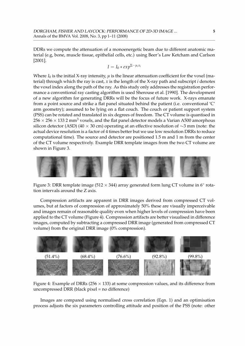
Where I0 is the initial X-ray intensity, µ is the linear attenuation coefficient for the voxel (ma-terial) through which the ray is cast, x is the length of the X-ray path and subscript i denotesthe voxel index along the path of the ray. As this study only addresses the registration perfor-mance a conventional ray casting algorithm is used Sherouse et al. [1990]. The developmentof a new algorithm for generating DRRs will be the focus of future work. X-rays emanatefrom a point source and strike a flat panel situated behind the patient (i.e. conventional ‘C’arm geometry); assumed to be lying on a flat couch. The couch or patient support system(PSS) can be rotated and translated in six degrees of freedom. The CT volume is quantised in256× 256× 133 2 mm3 voxels, and the flat panel detector models a Varian A500 amorphoussilicon detector (ASD) (40 × 30 cm) operating at an effective resolution of ∼3 mm (note: theactual device resolution is a factor of 4 times better but we use low resolution DRRs to reducecomputational time). The source and detector are positioned 1.5 m and 1 m from the centerof the CT volume respectively. Example DRR template images from the two CT volume areshown in Figure 3.
Figure 3: DRR template image (512× 344) array generated form lung CT volume in 6◦ rota-tion intervals around the Z axis.
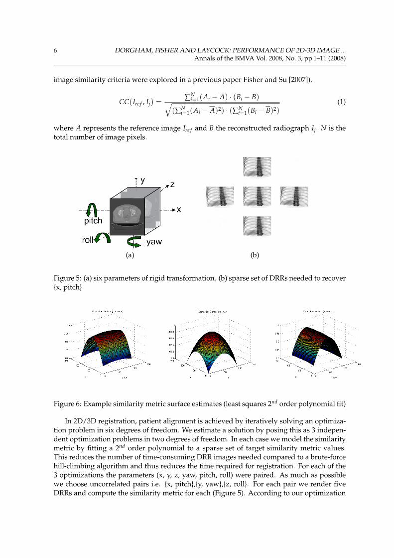
Compression artifacts are apparent in DRR images derived from compressed CT vol-umes, but at factors of compression of approximately 50% these are visually imperceivableand images remain of reasonable quality even when higher levels of compression have beenapplied to the CT volume (Figure 4). Compression artifacts are better visualised in differenceimages, computed by subtracting a compressed DRR image (generated from compressed CTvolume) from the original DRR image (0% compression).
(51.4%) (68.4%) (76.6%) (92.8%) (99.8%)
Figure 4: Example of DRRs (256× 133) at some compression values, and its difference fromuncompressed DRR (black pixel = no difference)
Images are compared using normalised cross correlation (Eqn. 1) and an optimisationprocess adjusts the six parameters controlling attitude and position of the PSS (note: other
6 DORGHAM, FISHER AND LAYCOCK: PERFORMANCE OF 2D-3D IMAGE ...Annals of the BMVA Vol. 2008, No. 3, pp 1–11 (2008)
image similarity criteria were explored in a previous paper Fisher and Su [2007]).
CC(Ire f , Ij) = ∑Ni=1(Ai − A) · (Bi − B)√
(∑Ni=1(Ai − A)2) · (∑N
i=1(Bi − B)2)(1)
where A represents the reference image Ire f and B the reconstructed radiograph Ij. N is thetotal number of image pixels.
(a) (b)
Figure 5: (a) six parameters of rigid transformation. (b) sparse set of DRRs needed to recover{x, pitch}
Figure 6: Example similarity metric surface estimates (least squares 2nd order polynomial fit)
In 2D/3D registration, patient alignment is achieved by iteratively solving an optimiza-tion problem in six degrees of freedom. We estimate a solution by posing this as 3 indepen-dent optimization problems in two degrees of freedom. In each case we model the similaritymetric by fitting a 2nd order polynomial to a sparse set of target similarity metric values.This reduces the number of time-consuming DRR images needed compared to a brute-forcehill-climbing algorithm and thus reduces the time required for registration. For each of the3 optimizations the parameters (x, y, z, yaw, pitch, roll) were paired. As much as possiblewe choose uncorrelated pairs i.e. {x, pitch},{y, yaw},{z, roll}. For each pair we render fiveDRRs and compute the similarity metric for each (Figure 5). According to our optimization
DORGHAM, FISHER AND LAYCOCK: PERFORMANCE OF 2D-3D IMAGE ... 7Annals of the BMVA Vol. 2008, No. 3, pp 1–11 (2008)
strategy 15 DRRs (3× 5) need to be generated in each iteration, which is substantially fewerDRRs than and equivalent conventional best neighbour search Törn and Zilinskas [1989]. Ateach iteration the maximum of the similarity metric distribution is calculated using the 2nd
order model and the procedure is terminated when the error in the recovered PSS parame-ters found in successive iterations becomes negligible. Typical models for the three similaritymetric surfaces are shown in Figure 6. In Qi and Gu [2008] the authors use a similar opti-misation approach but estimate the the similarity metric distribution from a sparse set ofvalues using a Support Vector Machine (SVM).
3 Results
CT volume Size / Compression (%)P 323 643 1283 2563
0 32768 0% 262144 0% 2097152 0% 16777216 0%0.001 20469 37.53% 149248 43.07% 1097804 47.65% 8159096 51.37%0.005 18145 44.63% 118903 54.64% 818595 60.97% 5293744 68.45%0.01 16017 51.12% 100108 61.81% 643455 69.32% 3925720 76.60%0.015 14904 54.52% 92457 64.73% 550565 73.75% 3342557 80.08%0.02 14400 56.05% 85800 67.27% 464850 77.83% 2718829 83.79%0.03 14022 57.21% 80382 69.34% 417075 80.11% 2337959 86.06%0.04 12874 60.71% 72465 72.36% 358079 82.93% 1929607 88.50%0.07 9948 69.64% 52592 79.94% 267485 87.25% 1423241 91.52%0.2 6483 80.22% 35792 86.35% 141051 93.27% 556872 96.68%0.3 4628 85.88% 25705 90.19% 93073 95.56% 249425 98.51%0.7 162 99.51% 239 99.91% 377 99.98% 1142 99.99%1 1 100% 1 100% 1 100% 1 100%
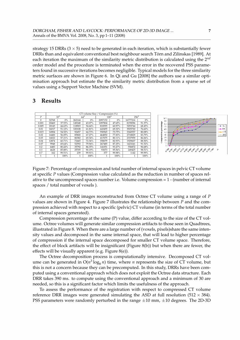
Figure 7: Percentage of compression and total number of internal spaces in pelvic CT volumeat specific P values (Compression value calculated as the reduction in number of spaces rel-ative to the uncompressed spaces number i.e. Volume compression = 1 - (number of internalspaces / total number of voxels ).
An example of DRR images reconstructed from Octree CT volume using a range of Pvalues are shown in Figure 4. Figure 7 illustrates the relationship between P and the com-pression achieved with respect to a specific (pelvic) CT volume (in terms of the total numberof internal spaces generated).
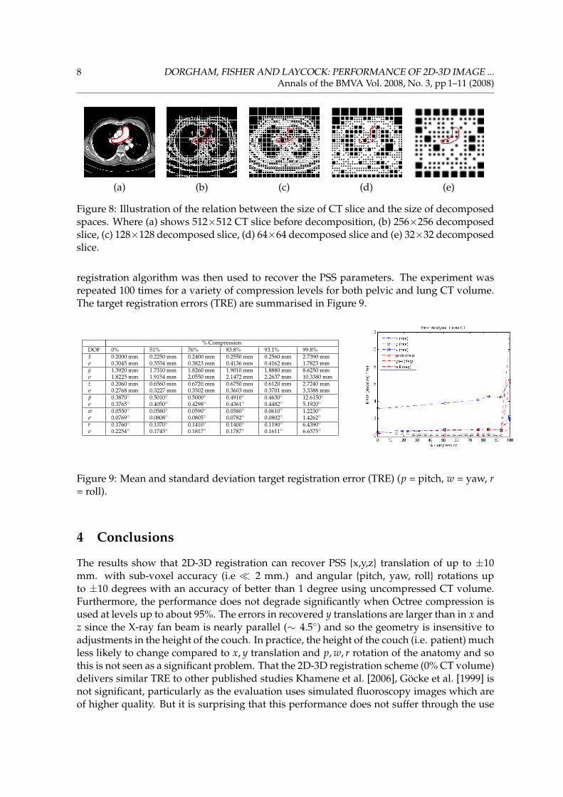
Compression percentage at the same (P) value, differ according to the size of the CT vol-ume. Octree volumes will generate similar compression artifacts to those seen in Quadtrees,illustrated in Figure 8. When there are a large number of (voxels, pixels)share the same inten-sity values and decomposed in the same internal space, that will lead to higher percentageof compression if the internal space decomposed for smaller CT volume space. Therefore,the effect of block artifacts will be insignificant (Figure 8(b)) but when there are fewer, theeffects will be visually apparent (e.g. Figure 8(e)).
The Octree decomposition process is computationally intensive. Decomposed CT vol-ume can be generated in O(n3 log8 n) time, where n represents the size of CT volume, butthis is not a concern because they can be precomputed. In this study, DRRs have been com-puted using a conventional approach which does not exploit the Octree data structure. EachDRR takes 390 ms. to compute using the conventional approach and a minimum of 30 areneeded, so this is a significant factor which limits the usefulness of the approach.
To assess the performance of the registration with respect to compressed CT volumereference DRR images were generated simulating the ASD at full resolution (512 × 384).PSS parameters were randomly perturbed in the range ±10 mm, ±10 degrees. The 2D-3D
8 DORGHAM, FISHER AND LAYCOCK: PERFORMANCE OF 2D-3D IMAGE ...Annals of the BMVA Vol. 2008, No. 3, pp 1–11 (2008)
(a) (b) (c) (d) (e)
Figure 8: Illustration of the relation between the size of CT slice and the size of decomposedspaces. Where (a) shows 512×512 CT slice before decomposition, (b) 256×256 decomposedslice, (c) 128×128 decomposed slice, (d) 64×64 decomposed slice and (e) 32×32 decomposedslice.
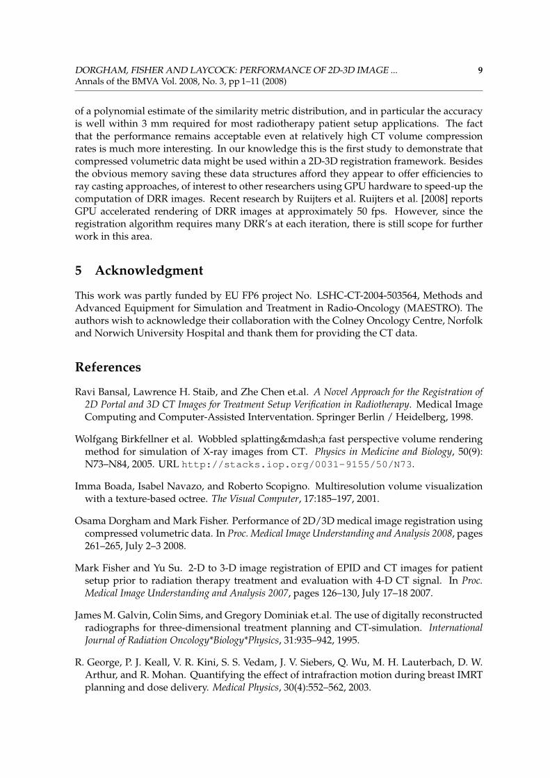
registration algorithm was then used to recover the PSS parameters. The experiment wasrepeated 100 times for a variety of compression levels for both pelvic and lung CT volume.The target registration errors (TRE) are summarised in Figure 9.
% CompressionDOF 0% 51% 76% 83.8% 93.1% 99.8%x 0.2000 mm 0.2250 mm 0.2400 mm 0.2550 mm 0.2560 mm 2.7390 mmσ 0.3045 mm 0.3554 mm 0.3823 mm 0.4136 mm 0.4162 mm 1.7823 mmy 1.3920 mm 1.7310 mm 1.8260 mm 1.9010 mm 1.8880 mm 8.6250 mmσ 1.8225 mm 1.9154 mm 2.0550 mm 2.1472 mm 2.2637 mm 10.3380 mmz 0.2060 mm 0.6560 mm 0.6720 mm 0.6750 mm 0.6120 mm 2.7240 mmσ 0.2768 mm 0.3227 mm 0.3502 mm 0.3603 mm 0.3701 mm 3.3388 mmp 0.3870◦ 0.5010◦ 0.5000◦ 0.4910◦ 0.4630◦ 12.6150◦σ 0.3765◦ 0.4050◦ 0.4298◦ 0.4361◦ 0.4482◦ 5.1920◦
w 0.0550◦ 0.0580◦ 0.0590◦ 0.0580◦ 0.0610◦ 1.2230◦σ 0.0769◦ 0.0808◦ 0.0805◦ 0.0782◦ 0.0802◦ 1.4262◦
r 0.1760◦ 0.1370◦ 0.1410◦ 0.1400◦ 0.1190◦ 6.4390◦σ 0.2254◦ 0.1745◦ 0.1817◦ 0.1787◦ 0.1611◦ 6.6575◦
Figure 9: Mean and standard deviation target registration error (TRE) (p = pitch, w = yaw, r= roll).
4 Conclusions
The results show that 2D-3D registration can recover PSS {x,y,z} translation of up to ±10mm. with sub-voxel accuracy (i.e � 2 mm.) and angular {pitch, yaw, roll} rotations upto ±10 degrees with an accuracy of better than 1 degree using uncompressed CT volume.Furthermore, the performance does not degrade significantly when Octree compression isused at levels up to about 95%. The errors in recovered y translations are larger than in x andz since the X-ray fan beam is nearly parallel (∼ 4.5◦) and so the geometry is insensitive toadjustments in the height of the couch. In practice, the height of the couch (i.e. patient) muchless likely to change compared to x, y translation and p, w, r rotation of the anatomy and sothis is not seen as a significant problem. That the 2D-3D registration scheme (0% CT volume)delivers similar TRE to other published studies Khamene et al. [2006], Göcke et al. [1999] isnot significant, particularly as the evaluation uses simulated fluoroscopy images which areof higher quality. But it is surprising that this performance does not suffer through the use
DORGHAM, FISHER AND LAYCOCK: PERFORMANCE OF 2D-3D IMAGE ... 9Annals of the BMVA Vol. 2008, No. 3, pp 1–11 (2008)
of a polynomial estimate of the similarity metric distribution, and in particular the accuracyis well within 3 mm required for most radiotherapy patient setup applications. The factthat the performance remains acceptable even at relatively high CT volume compressionrates is much more interesting. In our knowledge this is the first study to demonstrate thatcompressed volumetric data might be used within a 2D-3D registration framework. Besidesthe obvious memory saving these data structures afford they appear to offer efficiencies toray casting approaches, of interest to other researchers using GPU hardware to speed-up thecomputation of DRR images. Recent research by Ruijters et al. Ruijters et al. [2008] reportsGPU accelerated rendering of DRR images at approximately 50 fps. However, since theregistration algorithm requires many DRR’s at each iteration, there is still scope for furtherwork in this area.
5 Acknowledgment
This work was partly funded by EU FP6 project No. LSHC-CT-2004-503564, Methods andAdvanced Equipment for Simulation and Treatment in Radio-Oncology (MAESTRO). Theauthors wish to acknowledge their collaboration with the Colney Oncology Centre, Norfolkand Norwich University Hospital and thank them for providing the CT data.
References
Ravi Bansal, Lawrence H. Staib, and Zhe Chen et.al. A Novel Approach for the Registration of2D Portal and 3D CT Images for Treatment Setup Verification in Radiotherapy. Medical ImageComputing and Computer-Assisted Interventation. Springer Berlin / Heidelberg, 1998.
Wolfgang Birkfellner et al. Wobbled splatting—a fast perspective volume renderingmethod for simulation of X-ray images from CT. Physics in Medicine and Biology, 50(9):N73–N84, 2005. URL http://stacks.iop.org/0031-9155/50/N73.
Imma Boada, Isabel Navazo, and Roberto Scopigno. Multiresolution volume visualizationwith a texture-based octree. The Visual Computer, 17:185–197, 2001.
Osama Dorgham and Mark Fisher. Performance of 2D/3D medical image registration usingcompressed volumetric data. In Proc. Medical Image Understanding and Analysis 2008, pages261–265, July 2–3 2008.
Mark Fisher and Yu Su. 2-D to 3-D image registration of EPID and CT images for patientsetup prior to radiation therapy treatment and evaluation with 4-D CT signal. In Proc.Medical Image Understanding and Analysis 2007, pages 126–130, July 17–18 2007.
James M. Galvin, Colin Sims, and Gregory Dominiak et.al. The use of digitally reconstructedradiographs for three-dimensional treatment planning and CT-simulation. InternationalJournal of Radiation Oncology*Biology*Physics, 31:935–942, 1995.
R. George, P. J. Keall, V. R. Kini, S. S. Vedam, J. V. Siebers, Q. Wu, M. H. Lauterbach, D. W.Arthur, and R. Mohan. Quantifying the effect of intrafraction motion during breast IMRTplanning and dose delivery. Medical Physics, 30(4):552–562, 2003.
10 DORGHAM, FISHER AND LAYCOCK: PERFORMANCE OF 2D-3D IMAGE ...Annals of the BMVA Vol. 2008, No. 3, pp 1–11 (2008)
I. C. Gibbs. Frameless image-guided intracranial and extracranial radiosurgery using thecyberknife(tm) robotic system. Cancer/Radiotherapie, 10(5):283–287, 2006. doi: DOI:10.1016/j.canrad.2006.05.013.
Roland Göcke, Jürgen Weese, and Heidrum Schumann. Fast volume rendering methodsfor voxel-based 2D/3D registration - A comparative study. In Proc. 1st Int. Workshop onBiomedial Image Registration, pages 89–102, Beld, Slovenia, August 1999.
Tobias Gross. GPU-Based 2D/3D registration of X-ray and CT data. Master’s thesis, Institutefor Computer Graphics and Vision, Graz University of Technology, 2008.
G. M. Hunter. Efficient computation and data structures for graphics. PhD thesis, Dept. of Elec-trical Engineering and Computer Science, Princton University, 1978.
Chris L. Jackins and Steven L. Tonimoto. Oct-trees and their use in representing three-dimensional objects. Computer Graphics and Image Processing, 14(3):249–270, 1980.
Richard A. Ketcham and William D. Carlson. Acquisition, optimization and interpretationof X-ray computed tomographic imagery: applications to the geosciences. Comput. Geosci.,27:381–400, 2001.
Ali Khamene, Peter Bloch, and Wolfgang Wein et.al. Automatic registration of portal imagesand volumetric CT for patient positioning in radiation therapy. Medical Image Analysis, 10:96–112, 2006.
D. Knaan and L. Joskowicz. Efficient intensity-based 2D/3D rigid registration between flu-oroscopic X-ray and CT. In MICCAI 2003, 6th Int. Conf., Montréal, Canada, Part I, vol 2878of Lecture Notes in Computer Science, pages 351–358. Springer, 2003.
Philippe Lacroute and Marc Levoy. Fast volume rendering using a shear-warp factorizationof the viewing transformation. In Proc. SIGGRAPH ’94, pages 451–458, Orlando, Florida,July 1994.
David A. LaRose. Iterative X-ray/CT Registration Using Accelerated Volume Rendering. PhDthesis, Carnegie Mellon University, 2001.
Marc Levoy. Efficient ray tracing of volume data. ACM Transactions on Graphics, pages 249–261, July 1990.
P. Hanrahan M. Levoy. Light field rendering. 23rd Annu. Conf. Comput. Graph. Interact. Tech.SIGGRAPH, 96:31U42, 1996.
Graeme P. Penney, Philipp G. Batchelor, Derek L. G. Hill, David J. Hawkes, and JuergenWeese. Validation of a two- to three-dimensional registration algorithm for aligning pre-operative CT images and intraoperative fluoroscopy images. Medical Physics, 28(6):1024–1032, 2001. doi: 10.1118/1.1373400. URL http://link.aip.org/link/?MPH/28/1024/1.
Wenyuan Qi and Lixu Gu. Effective 2D-3D medical image registration using support vectormachine. In Proc. Annual Int. Conf. of IEEE Engineering in Medicine and Biology Society, pages5386–5389, 2008.
DORGHAM, FISHER AND LAYCOCK: PERFORMANCE OF 2D-3D IMAGE ... 11Annals of the BMVA Vol. 2008, No. 3, pp 1–11 (2008)
Daniel Ruijters, Bart M. ter Haar Romeny, and Paul Suetens. GPU-Accelerated digitallyreconstructed radiographs. In Proc. BioMed2008, Innsbruck, Austria, February 13–15 2008.
Daniel B. Russakoff, Torsten Rohlfing, and Kensaku Mori et.al. Fast generation of digitallyreconstructed radiographs using attenuation fields with application to 2D-3D image reg-istration. IEEE Transaction on Medical Imaging, 24:1441–1454, 2005.
Hanan Samet. The quadtree and related hierarchical data structures. ACM Computing Sur-veys, 16:188–260, 1984.
Lisa B. Schwartz, David L. Olive, and Shirley McCarthy. Diagnostic Imaging for ReproductiveFailure. Taylor and Francis Ltd, UK, 1998.
G.W. Sherouse, K. Novins, B.S. Chaney, and E.L. Chaney. Computation of digitally recon-structed radiographs for use in radiotherapy treatment design. Int. J. Radiation OncologyBiol. Phys., 18(3):651–658, March 1990.
K. Sikora, S. Advani, V. Koroltchouk, I. Magrath, L. Levy, H. Pinedo, G. Schwartsmann,M. Tattersall, and S. Yan. Essential drugs for cancer therapy: A world health organizationconsultation. Annals of Oncology, 10:385–390, 1999.
Weiwei Song, Shungang Hua, Zongying Ou, Hu An, and Kaifeng Song. Octree basedrepresentation and volume rendering of three-dimensional medical data sets. BioMed-ical Engineering and Informatics, International Conference on, 1:316–320, 2008. doi: http://doi.ieeecomputersociety.org/10.1109/BMEI.2008.287.
S. Tanimoto and T. Pavlidis. A hierarchical data structure for picture processing. ComputerGraphics and Image Processing, 4(2):104–119, June 1975.
A. Törn and A. Zilinskas. Global Optimisation. Springer-Verlag, Berlin, 1989.
Maximilien Vermandel, Nacim Betrouni, Georges Palos, Jean-Yves Gauvrit, ChristianVasseur, and Jean Rousseau. Registration, matching, and data fusion in 2D/3D medi-cal imaging: Application to dsa and mra. Medical Image Computing and Computer-AssistedIntervention - MICCAI 2003, 2878:778–785, 2003.
Z. L. Wang et al. Dynamic linear level octree-based volume rendering methods for interac-tive microsurgical simulation. Int. Journal of Image and Graphics, 6(2):155–171, April 2006.
Ziv Yaniv and Kevin Clearly. Image guided procedures: A review. Technical Report TR-2006-3, Georgetown University, Image Science and Information Centre, Washington DC,April 2006.