Performance Evaluation of a Supercritical CO2 Power Cycle Coal...
20
© 2016 Electric Power Research Institute, Inc. All rights reserved. Scott Hume Principal Technical Leader The 5th International Symposium - Supercritical CO 2 Power Cycles March 28-31, 2016, San Antonio, Texas Performance Evaluation of a Supercritical CO 2 Power Cycle Coal Gasification Plant
Transcript of Performance Evaluation of a Supercritical CO2 Power Cycle Coal...

© 2016 Electric Power Research Institute, Inc. All rights reserved.
Scott Hume
Principal Technical Leader
The 5th International Symposium -
Supercritical CO2 Power Cycles
March 28-31, 2016, San Antonio, Texas
Performance Evaluation
of a Supercritical CO2
Power Cycle Coal
Gasification Plant

2© 2016 Electric Power Research Institute, Inc. All rights reserved.
Structure
Introduction
Background
– Base Case IGCC
– Base Case IGCC with Capture
Brayton Power Cycle
Plant Design Basis
Modeling Approach
Results
– Performance
– Design Considerations
Conclusions

3© 2016 Electric Power Research Institute, Inc. All rights reserved.
Introduction
Supercritical CO2 Cycles offer the potential
for high net efficiency of 48.9% (HHV) [1]
from coal
Advanced IGCC design, novel plant
components
[1] – R.J. Allam et al, “High efficiency and low cost of electricity generation from fossil fuels while eliminating atmospheric emissions, including carbon dioxide”
GHGT-11 - 18th-22nd November 2012, Kyoto International Conference Center, Japan
• Investigation of sCO2 Brayton coupled to a
‘conventional IGCC gasifier design’
• IGCC Plant based on EPRI report
1015699 (2009) [2]
[2] – Integrated Gasification Combined Cycle (IGCC) Design Considerations for Carbon Dioxide (CO2) Capture, Schoff, R EPRI Report 1015690, 2009

4© 2016 Electric Power Research Institute, Inc. All rights reserved.
Background - Base Case IGCC Plant
Shell Syngas Cooler (SGC) design
Medium pressure technology (43 barg)
Oxygen purity 95% v/v
Pressurized dry gas feed
No CO shift or CO2 removal
Selexol acid gas removal
GE 7FB combustion turbine + HRSG
System Fuel Input 1470
Gas Turbine Output 464
Steam Turbine Output 235
CO2 LP Compression -
HP Pumps -
Fuel Compression -
Oxygen Compression -
IGCC Aux 16.2
ASU 74.4
Steam Cycle Aux 8.2
Cooling Water Aux 11.1
Net Power 587.9
Power Plant Efficiency (HHV) 40.0%
CO2 lb/MWh 1770
CGS
British
COAL MILLING &
DRYING
GASIFICATION ISLAND
SYNGAS COOLING
ACID GAS REMOVAL
AIR SEPARATION
UNIT
GAS TURBINE
HRSGCOOLING WATER
STACK
OXYGEN
NITROGEN
SULFUR RECOVERY
STEAM TURBINE ISLAND
AIRAIR
WET COAL SYNGAS TREATMENT
N2 TF
SULFUR
TAIL GAS RECYCLE
Moderator Steam
N2 Injection
SYNGAS
POWER
POWER
5© 2016 Electric Power Research Institute, Inc. All rights reserved.
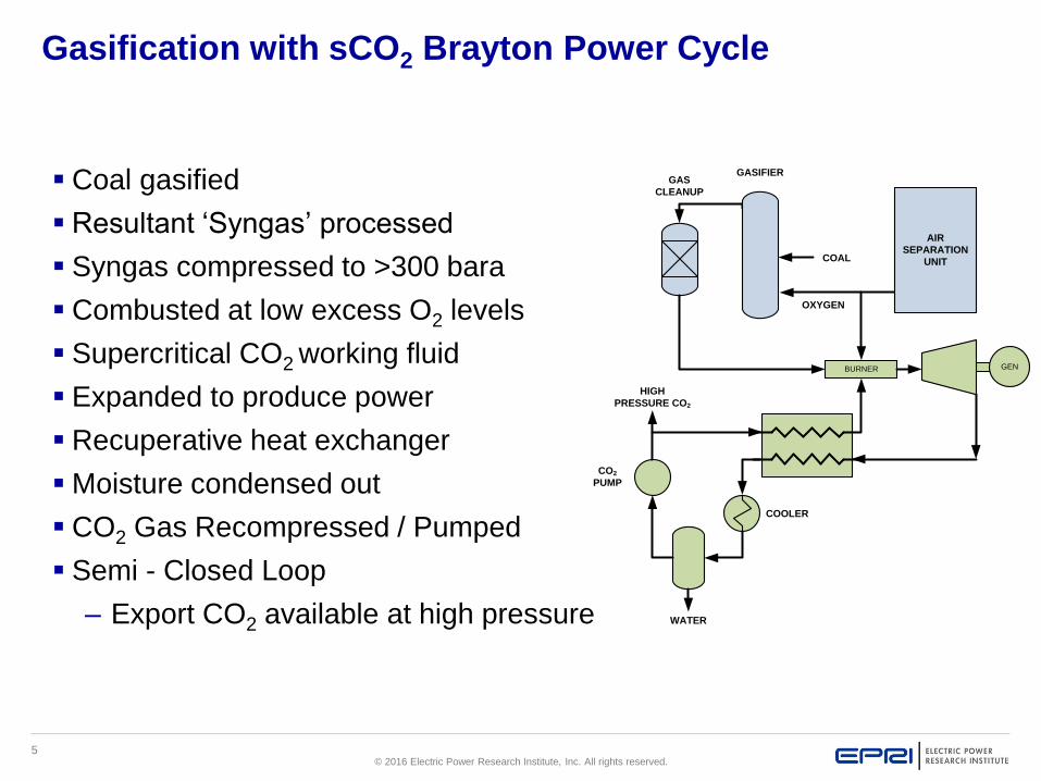
Gasification with sCO2 Brayton Power Cycle
Coal gasified
Resultant ‘Syngas’ processed
Syngas compressed to >300 bara
Combusted at low excess O2 levels
Supercritical CO2 working fluid
Expanded to produce power
Recuperative heat exchanger
Moisture condensed out
CO2 Gas Recompressed / Pumped
Semi - Closed Loop
– Export CO2 available at high pressure
GENBURNER
COAL
GASIFIERGAS
CLEANUP
AIR
SEPARATION
UNIT
OXYGEN
WATER
COOLER
CO2
PUMP
HIGH
PRESSURE CO2

6© 2016 Electric Power Research Institute, Inc. All rights reserved.
‘Closed’ Brayton Cycle
Work
Combustion Heat
Recovered HeatCO2
H2O
CO H2 O2
Heat Rejection
~700°C
~760°C

7© 2016 Electric Power Research Institute, Inc. All rights reserved.
Plant Design Basis
Conventional gasification system
PRB Fuel
273 tonnes/hr feed (1470MWth HHV)
NH3, COS, H2S, Mercury removal
Steam Cycle 565°C / 125 bara
Max 700°C CO2 feed to burner
Turbine Inlet Temperature ~1150°C
Max 760°C gas turbine exhaust
Heat Exchanger min 20°K approach
CO2 delivered pressure ~150 bara
3 cases developed:
– 1 Conventional Nitrogen Transfer Fluid
– 2 Carbon Dioxide Transfer Fluid
– 3 Case 2 except with High Purity Oxygen

8© 2016 Electric Power Research Institute, Inc. All rights reserved.
Case 1 – N2TF
Nitrogen transfer fluid (as before)
Gasification plant – Syngas production unchanged IGCC Output: Syngas Product
Compostion CO 58.32% v/v(w)
H2 27.91% v/v(w)
CO2 1.56% v/v(w)
N2 11.21% v/v(w)
Ar 0.86% v/v(w)
Others 0.15% v/v(w)
Massflow 375407 kg/hr
• New power block – ultra high pressure gas turbine
• Syngas cooler – complete boiler unit
• ASU capacity increased, oxygen purity 95% v/v
• Moderator steam remains

9© 2016 Electric Power Research Institute, Inc. All rights reserved.
CGS
British
AIR
WET COAL
Moderator Steam
COOLING WATER
COALMILLING &
DRYING
GASIFICATIONISLAND
SYNGAS COOLING
ACID GAS REMOVAL
AIR SEPARATION
UNIT
OXYGEN
NITROGEN
SULFURRECOVERY
STEAM TURBINE ISLAND
HEAT EXCHANGER
CONDENSER
CO2 PRODUCT TREATMENT
SYNGAS TREATMENT
CO2 PRODUCT
ACID WATER
SULFUR
TAIL GAS RECYCLE
COMPRESSORS& PUMPS
EXPANDER
COMBUSTOR
POWER
POWER
NEW EQUIPMENT
MODIFIED
CO2 Transfer Fluid
CO2 TF
Case 2 – CO2TF
Transfer Fluid sourced from CO2 working fluid
Nitrogen content reduced over 90% from Case 1
Gasifier process changed – increased CO content
No moderator steam, syngas CO2 content higher
Lower hydrogen content
Oxygen purity at 95% v/v
IGCC Output: Syngas Product
Compostion CO 68.32% v/v(w)
H2 22.58% v/v(w)
CO2 6.56% v/v(w)
N2 1.06% v/v(w)
Ar 1.39% v/v(w)
Others 0.09% v/v(w)
Massflow 388165 kg/hr

10© 2016 Electric Power Research Institute, Inc. All rights reserved.
CGS
British
AIR
WET COAL
Moderator Steam
COOLING WATER
COALMILLING &
DRYING
GASIFICATIONISLAND
SYNGAS COOLING
ACID GAS REMOVAL
AIR SEPARATION
UNIT
OXYGEN
NITROGEN
SULFURRECOVERY
STEAM TURBINE ISLAND
HEAT EXCHANGER
CONDENSER
CO2 PRODUCT TREATMENT
SYNGAS TREATMENT
CO2 PRODUCT
ACID WATER
SULFUR
TAIL GAS RECYCLE
COMPRESSORS& PUMPS
EXPANDER
COMBUSTOR
POWER
POWER
NEW EQUIPMENT
MODIFIED
CO2 Transfer Fluid
CO2 TF
Case 3 – CO2TF (HPO)
Similar to Case 2 except:
ASU Oxygen purity increased to 99.5% v/v
Nitrogen content reduced further by over 50%
Argon content very low
IGCC Output: Syngas Product
Compostion CO 69.59% v/v(w)
H2 22.71% v/v(w)
CO2 6.94% v/v(w)
N2 0.50% v/v(w)
Ar 0.17% v/v(w)
Others 0.09% v/v(w)
Massflow 380393 kg/hr

11© 2016 Electric Power Research Institute, Inc. All rights reserved.
Compression Analysis – Pure CO2
Dense Phase -'Liquid-like'
Incompressible: Liquid
Gas-like
12© 2016 Electric Power Research Institute, Inc. All rights reserved.
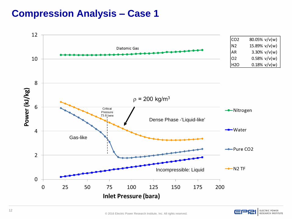
Compression Analysis – Case 1
CO2 80.05% v/v(w)
N2 15.89% v/v(w)
AR 3.30% v/v(w)
O2 0.58% v/v(w)
H2O 0.18% v/v(w)
Dense Phase -'Liquid-like'
Incompressible: Liquid
Gas-like

13© 2016 Electric Power Research Institute, Inc. All rights reserved.
CO2 93.19% v/v(w)
N2 2.23% v/v(w)
AR 3.83% v/v(w)
O2 0.57% v/v(w)
H2O 0.18% v/v(w)
Compression Analysis – Case 2
Dense Phase -'Liquid-like'
Incompressible: Liquid
Gas-like

14© 2016 Electric Power Research Institute, Inc. All rights reserved.
Compression Analysis – Case 3
Dense Phase -'Liquid-like'
Incompressible: Liquid
Gas-like
CO2 98.06% v/v(w)
N2 0.68% v/v(w)
AR 0.48% v/v(w)
O2 0.59% v/v(w)
H2O 0.18% v/v(w)

15© 2016 Electric Power Research Institute, Inc. All rights reserved.
Performance Results - Product Purity

16© 2016 Electric Power Research Institute, Inc. All rights reserved.
40.0% 40.5% 39.6% 39.6%
0.0%
10.0%
20.0%
30.0%
40.0%
50.0%
60.0%
70.0%
IGCC (no capture) IGBCN2 TF
IGBCCO2 TF
IGBCHPO
Plant Efficiency (HHV)
Net CO2 Aux Plant Aux
Performance Results - Power
CO2 Purity
~ 80%vol
~ similar
output
CO2 Purity
~ 93%vol
CO2 Purity
~ 98%vol
IGCC
Low purity CO2
working fluid delivers
more power but not
within product
specification
Case 3 (HPO) meets
specification and
achieves near 100%
capture with similar
power output
17© 2016 Electric Power Research Institute, Inc. All rights reserved.
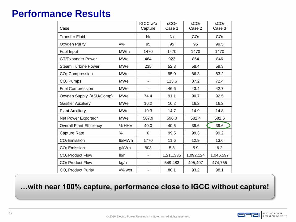
Case IGCC w/o Capture
sCO2 Case 1
sCO2 Case 2
sCO2 Case 3
Transfer Fluid N2 N2 CO2 CO2
Oxygen Purity v% 95 95 95 99.5
Fuel Input MWth 1470 1470 1470 1470
GT/Expander Power MWe 464 922 864 846
Steam Turbine Power MWe 235 52.3 58.4 59.3
CO2 Compression MWe - 95.0 86.3 83.2
CO2 Pumps MWe - 113.6 87.2 72.4
Fuel Compression MWe - 46.6 43.4 42.7
Oxygen Supply (ASU/Comp) MWe 74.4 91.1 90.7 92.5
Gasifier Auxiliary MWe 16.2 16.2 16.2 16.2
Plant Auxiliary MWe 19.3 14.7 14.9 14.8
Net Power Exported* MWe 587.9 596.0 582.4 582.6
Overall Plant Efficiency % HHV 40.0 40.5 39.6 39.6
Capture Rate % 0 99.5 99.3 99.2
CO2 Emission lb/MWh 1770 11.6 12.9 13.6
CO2 Emission g/kWh 803 5.3 5.9 6.2
CO2 Product Flow lb/h - 1,211,335 1,092,124 1,046,597
CO2 Product Flow kg/h - 549,483 495,407 474,755
CO2 Product Purity v% wet - 80.1 93.2 98.1
Performance Results
…with near 100% capture, performance close to IGCC without capture!

18© 2016 Electric Power Research Institute, Inc. All rights reserved.
Technical Risks
Higher Pressure Gasification
Exchanger and Piping
Combustor Design – ultra low oxygen
Expander Design
– Integrally cooled HP blades
– High temperature materials
High & low temperature corrosion
CO2 Product Purity (oxygen)
Ultra high pressure CO2 Safety

19© 2016 Electric Power Research Institute, Inc. All rights reserved.
Conclusions and Recommendations
Superior low carbon performance
Proven gasification technology
Near 100% capture
Opportunities to improve efficiency
Future areas of investigation
sCO2 turbine development
Combustion performance
Heat exchanger cost reduction
Economic cycle optimization
Product gas purity improvement
GENBURNER
COAL
GASIFIERGAS
CLEANUP
AIR
SEPARATION
UNIT
OXYGEN
WATER
COOLER
CO2
PUMP
HIGH
PRESSURE CO2

20© 2016 Electric Power Research Institute, Inc. All rights reserved.
Together…Shaping the Future of Electricity