
Performance Enhancements for Kinetic Hydropower Abstract
16
Performance Enhancements for Kinetic Hydropower David L. F. Gaden, Research Associate, University of Manitoba Eric L. Bibeau, Assistant Professor, University of Manitoba Abstract River and ocean kinetic hydropower are emerging technologies that use submerged turbines to produce power from existing water currents. These alternatives that supplement conventional hydropower have a promising future, and have seen much recent development. The technology has many advantages that give it an obvious foothold in the alternative energy industry, such as its long-term relatively low cost, minimal environmental impact and versatility. The technology is applicable to river, marine currents, and tidal energy sources, thus offering a diversity of installation sites. However, by their nature, kinetic turbines involve external flow. As such, they are exposed to less than ideal conditions, such as turbulent, debris-laden flows during spring run-off and potential large boulders during storms. Furthermore, they do not have the benefits of other hydro technologies where the entire flow regime can be controlled with the geometry of the channel, which allows for inlet nozzles and outlet diffusers that can increase the efficiency. This study will review several developments in kinetic hydro that attempt to overcome these problems. The results of recent experiments regarding two such solutions will be examined in more detail. Another goal of this presentation is to raise awareness of kinetic hydropower for river applications. An overview of the technology will be given, as well as a review of recent developments, including upcoming projects. Introduction Rapid growth in energy consumption and environmental concerns over conventional power generation technologies has given rise to a need for renewable energy sources. In terms of energy production, hydropower is by far the dominant form of renewable energy along with biomass. Its modern history arcs back to the 1880’s when hydroelectric dams first began sprouting across North America. By the 1940’s, hydropower accounted for over 30% of U.S. energy production. However, this was followed by a decline in suitable large capacity sites, as well as price competition from increasingly cheaper coal- and oil-fired plants. Since then, interest in hydroelectricity has flowed in and out with the tide of fossil fuel prices, and more recently, environmental concerns. With suitable sites for large hydroelectric dams mainly used in North America, the future of hydroelectricity lies in developing remaining large hydro sites, run-of-river, small hydro and recently emerging hydro applications as climate change, peak oil, sustainability and clean air can only be addressed by developing a large portfolio of renewable energy options. There is nothing new in this reasoning. Indeed, conventional hydroelectric plants have been scaled down several orders of magnitude, from large hydro, through small hydro, to mini hydro. But ultimately, conventional hydroelectric plants still require a dam, powerhouse, and usually a spillway and reservoir. These all have environmental impacts and geographic footprints. Kinetic hydropower installation may potentially have less of an environmental impact when compared on a per kWhr basis but suffer from much lower power densities.
Transcript of Performance Enhancements for Kinetic Hydropower Abstract

Performance Enhancements for Kinetic Hydropower
David L. F. Gaden, Research Associate, University of Manitoba Eric L. Bibeau, Assistant Professor, University of Manitoba
Abstract River and ocean kinetic hydropower are emerging technologies that use submerged turbines to produce power from existing water currents. These alternatives that supplement conventional hydropower have a promising future, and have seen much recent development. The technology has many advantages that give it an obvious foothold in the alternative energy industry, such as its long-term relatively low cost, minimal environmental impact and versatility. The technology is applicable to river, marine currents, and tidal energy sources, thus offering a diversity of installation sites. However, by their nature, kinetic turbines involve external flow. As such, they are exposed to less than ideal conditions, such as turbulent, debris-laden flows during spring run-off and potential large boulders during storms. Furthermore, they do not have the benefits of other hydro technologies where the entire flow regime can be controlled with the geometry of the channel, which allows for inlet nozzles and outlet diffusers that can increase the efficiency. This study will review several developments in kinetic hydro that attempt to overcome these problems. The results of recent experiments regarding two such solutions will be examined in more detail. Another goal of this presentation is to raise awareness of kinetic hydropower for river applications. An overview of the technology will be given, as well as a review of recent developments, including upcoming projects.
Introduction Rapid growth in energy consumption and environmental concerns over conventional power generation technologies has given rise to a need for renewable energy sources. In terms of energy production, hydropower is by far the dominant form of renewable energy along with biomass. Its modern history arcs back to the 1880’s when hydroelectric dams first began sprouting across North America. By the 1940’s, hydropower accounted for over 30% of U.S. energy production. However, this was followed by a decline in suitable large capacity sites, as well as price competition from increasingly cheaper coal- and oil-fired plants. Since then, interest in hydroelectricity has flowed in and out with the tide of fossil fuel prices, and more recently, environmental concerns. With suitable sites for large hydroelectric dams mainly used in North America, the future of hydroelectricity lies in developing remaining large hydro sites, run-of-river, small hydro and recently emerging hydro applications as climate change, peak oil, sustainability and clean air can only be addressed by developing a large portfolio of renewable energy options. There is nothing new in this reasoning. Indeed, conventional hydroelectric plants have been scaled down several orders of magnitude, from large hydro, through small hydro, to mini hydro. But ultimately, conventional hydroelectric plants still require a dam, powerhouse, and usually a spillway and reservoir. These all have environmental impacts and geographic footprints. Kinetic hydropower installation may potentially have less of an environmental impact when compared on a per kWhr basis but suffer from much lower power densities.
Kinetic hydropower first debuted in its modern form in the 1970’s with the Coriolis program. Since then, interest in its development, although slow at first, has grown significantly. Kinetic hydropower has many advantages over other forms of hydroelectricity that give it a clear foothold in the alternative energy market. However, kinetic hydropower also faces some challenges that more conventional technologies do not. Most of these challenges can be attributed, at least in part, to one underlying factor: external flow. Unlike other hydropower technologies, kinetic turbines are exposed to external flow conditions, and these adverse conditions create unseen obstacles that have hindered the development of this technology. However, engineers can eventually find solutions to overcome these conditions.
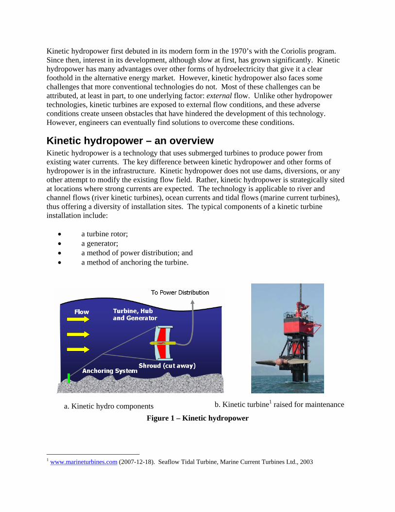
Kinetic hydropower – an overview Kinetic hydropower is a technology that uses submerged turbines to produce power from existing water currents. The key difference between kinetic hydropower and other forms of hydropower is in the infrastructure. Kinetic hydropower does not use dams, diversions, or any other attempt to modify the existing flow field. Rather, kinetic hydropower is strategically sited at locations where strong currents are expected. The technology is applicable to river and channel flows (river kinetic turbines), ocean currents and tidal flows (marine current turbines), thus offering a diversity of installation sites. The typical components of a kinetic turbine installation include:
• a turbine rotor; • a generator; • a method of power distribution; and • a method of anchoring the turbine.
b. Kinetic turbine1 raised for maintenance a. Kinetic hydro components Figure 1 – Kinetic hydropower
1 www.marineturbines.com (2007-12-18). Seaflow Tidal Turbine, Marine Current Turbines Ltd., 2003
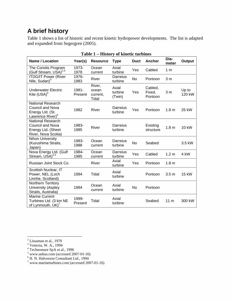
A brief history Table 1 shows a list of historic and recent kinetic hydropower developments. The list is adapted and expanded from Segergren (2005).
Table 1 – History of kinetic turbines Name / Location Year(s) Resource Type Duct Anchor Dia-
meter Output
The Coriolis Program (Gulf Stream, USA)2,3
1973-1978
Ocean current
Axial turbine Yes Cabled 1 m
ITDG/IT Power (River Nile, Sudan)4
1976-1983 River Darreius
turbine No Pontoon 3 m
Underwater Electric Kite (USA)5
1981-Present
River, ocean current, Tidal
Axial turbine (Twin)
Yes Cabled, Fixed, Pontoon
3 m Up to 120 kW
National Research Council and Nova Energy Ltd. (St. Lawrence River)6
1982 River Darreius turbine Yes Pontoon 1.8 m 25 kW
National Research Council and Nova Energy Ltd. (Sheet River, Nova Scotia)
1983-1985 River Darreius
turbine Existing structure 1.8 m 10 kW
Nihon University (Kurushima Straits, Japan)
1983-1988
Ocean current
Darreius turbine No Seabed 3.5 kW
Nova Energy Ltd. (Gulf Stream, USA)3,4
1984-1985
Ocean current
Darreius turbine Yes Cabled 1.2 m 4 kW
Russian Joint Stock Co. River Axial turbine Yes Pontoon 1.8 m
Scottish Nuclear, IT Power, NEL (Loch Linnhe, Scotland)
1994 Tidal Axial turbine Pontoon 3.5 m 15 kW
Northern Territory University (Aspley Straits, Australia)
1994 Ocean current
Axial turbine No Pontoon
Marine Current Turbines Ltd. (3 km NE of Lynmouth, UK)7
1999-Present Tidal Axial
turbine Seabed 11 m 300 kW
2 Lissaman et al., 1979 3 Venezia, W. A., 1994 4 Technomare SpA et al., 1996 5 www.uekus.com (accessed 2007-01-16) 6 H. N. Halvorson Consultant Ltd., 1994 7 www.marineturbines.com (accessed 2007-01-16)
Name / Location Year(s) Resource Type Duct Anchor Dia- meter Output
Ontario Power Generation, UEK, St. Catharines, Ontario8,9
2000 River Axial turbine (Twin)
Yes Cabled 3 m < 30 kW
Hammerfest Strøm AS (Strait of Kvalsundet, Norway)10
2002 Tidal Axial turbine Seabed 20 m 300 kW
Exim and Seapower (Sweden / Scotland)11
2002-Present Ocean Savonius
turbine Buoyed
Hydro Venturi Ltd.12 2002-Present
River, Tidal
Axial turbine Yes Existing
structure
TidEl Generator13 2003-Present Tidal Axial
turbine No Cabled 1.3 m
Lunar system14 2003-Present Tidal Axial
turbine Yes Seabed
Engineering Business Ltd, Stingray Tidal Stream Generator15
2002-Present Tidal
Hydro-plane actuation
No Seabed N/A 150 kW
New Energy Corporation, Alberta16
2003- present
River and tidal
Darreius turbine Yes Various 1.0 m 5 –
25 kW Pearson College, EnCana, Clean Current (Race Rocks, British Columbia)17
2004-Present Tidal Axial
turbine Yes Seabed
Stafkraft Development, Norway18
2004-Present Tidal Axial
turbine No Pontoon 15 m
Verdant Power (East River, New York, USA)
2006-Present Tidal Axial
turbine No Seabed 4.9 m 175 kW
University of Manitoba, Manitoba Hydro, UEK (Point du Bois)
2005- River Axial turbine Yes Granit
riverbed 3 m 60 kW
University of Manitoba, Manitoba Hydro, New Energy (Point du Bois)
2007- River Darreius turbine No Granit
riverbed <1 m 5 kW
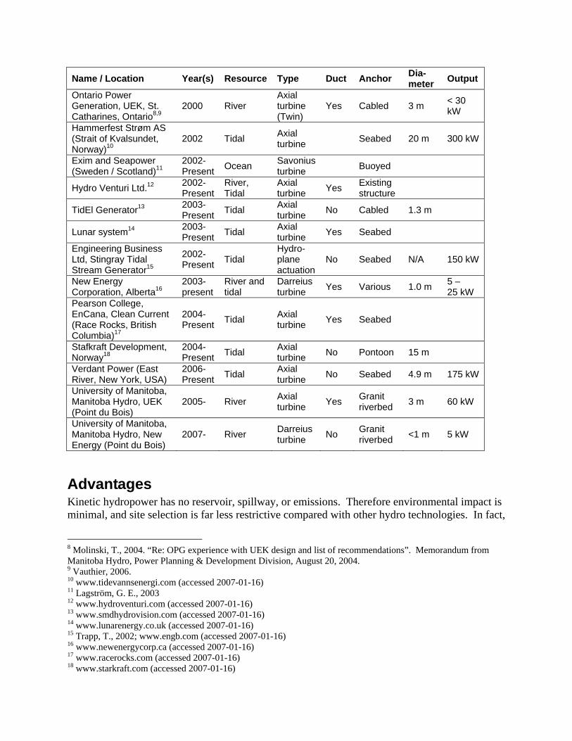
Advantages Kinetic hydropower has no reservoir, spillway, or emissions. Therefore environmental impact is minimal, and site selection is far less restrictive compared with other hydro technologies. In fact,
8 Molinski, T., 2004. “Re: OPG experience with UEK design and list of recommendations”. Memorandum from Manitoba Hydro, Power Planning & Development Division, August 20, 2004. 9 Vauthier, 2006. 10 www.tidevannsenergi.com (accessed 2007-01-16) 11 Lagström, G. E., 2003 12 www.hydroventuri.com (accessed 2007-01-16) 13 www.smdhydrovision.com (accessed 2007-01-16) 14 www.lunarenergy.co.uk (accessed 2007-01-16) 15 Trapp, T., 2002; www.engb.com (accessed 2007-01-16) 16 www.newenergycorp.ca (accessed 2007-01-16) 17 www.racerocks.com (accessed 2007-01-16) 18 www.starkraft.com (accessed 2007-01-16)

with a fully-submerged design, the turbine has no visible presence. This might help infiltrate urban areas, as well as coastal areas without impeding boat passage or obstructing the view. Compared to large hydro designs, the initial installation cost and deployment time is small as kinetic hydropower does not require significant infrastructure, such as dams or powerhouses but cannot deliver the energy capacity: comparisons are counterproductive. The modular nature of kinetic hydropower leads to an easily scalable energy output. Lastly, the consistent river velocities leads to steady energy production, thus eliminating the need for any significant energy storage or back-up capacity.
Disadvantages – external flow External flow refers to the situation when an object is much smaller than the bulk of the fluid flow, as shown in Figure 2. Conditions are far less controllable for external flow than internal flow. With internal flow, the fluid boundaries are part of the design, and therefore they may be changed to the advantage of the turbine. With external flow, this is not much less possible. Furthermore, an external flow design must accept any adverse upstream conditions.
Figure 2 – External and internal flow By their nature, kinetic turbines involve external flow, and therefore they are exposed to less than ideal conditions, such as turbulent and debris-laden flows, including fallen trees during spring run-off and boulders or rock slides during coastal storms that can seriously damage or destroy a turbine. Furthermore, kinetic hydropower does not allow for inlet nozzles, or outlet draft tubes, components of conventional hydropower that can improve the energy density. Kinetic turbines draw power only from the kinetic energy of the fluid flow in the same way that wind turbines do but the friction from the ocean floor or riverbed significantly impacts the potential power a turbine can produce especially for river applications. This region of reduced current is caused by the boundary-layer, and can reduce the available power by over 80%.
Designing for external flow The key problems caused by external flow conditions that kinetic turbines face are:
• low energy density – compared to conventional hydropower, kinetic hydropower has smaller energy densities available due to the fact that a large pressure difference cannot be achieved across a turbine in open flow; and
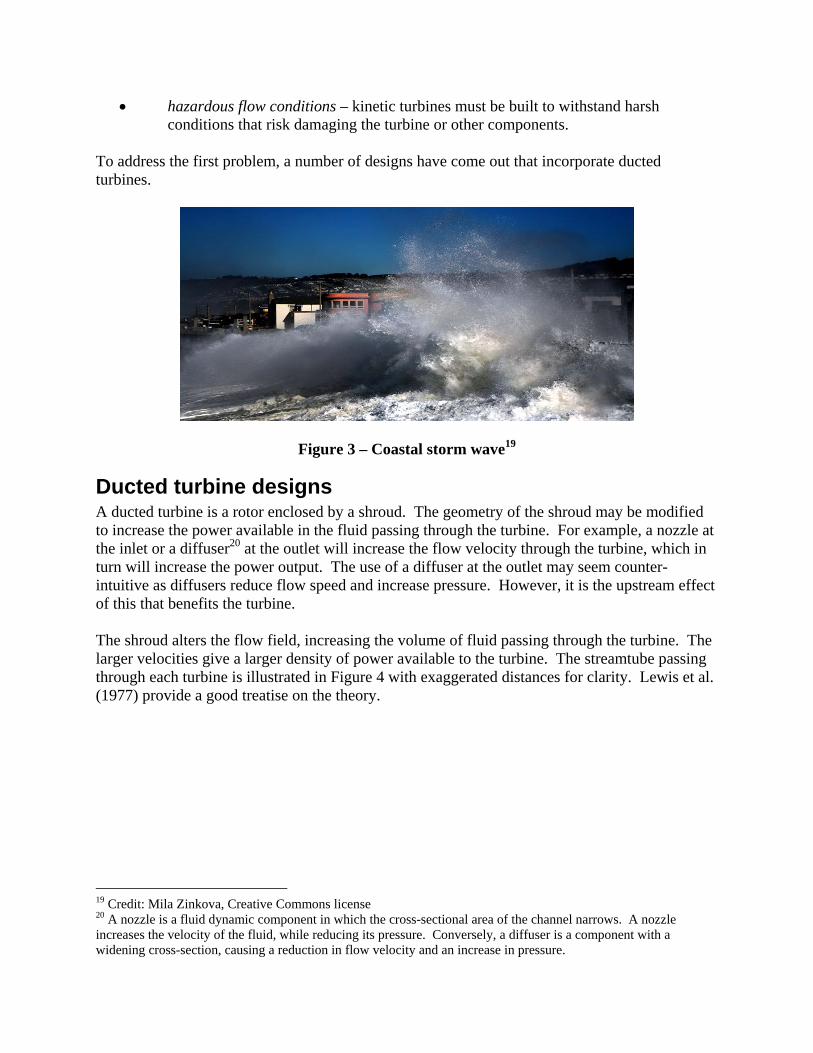
• hazardous flow conditions – kinetic turbines must be built to withstand harsh conditions that risk damaging the turbine or other components.
To address the first problem, a number of designs have come out that incorporate ducted turbines.
Figure 3 – Coastal storm wave19
Ducted turbine designs A ducted turbine is a rotor enclosed by a shroud. The geometry of the shroud may be modified to increase the power available in the fluid passing through the turbine. For example, a nozzle at the inlet or a diffuser20 at the outlet will increase the flow velocity through the turbine, which in turn will increase the power output. The use of a diffuser at the outlet may seem counter-intuitive as diffusers reduce flow speed and increase pressure. However, it is the upstream effect of this that benefits the turbine. The shroud alters the flow field, increasing the volume of fluid passing through the turbine. The larger velocities give a larger density of power available to the turbine. The streamtube passing through each turbine is illustrated in Figure 4 with exaggerated distances for clarity. Lewis et al. (1977) provide a good treatise on the theory.
19 Credit: Mila Zinkova, Creative Commons license 20 A nozzle is a fluid dynamic component in which the cross-sectional area of the channel narrows. A nozzle increases the velocity of the fluid, while reducing its pressure. Conversely, a diffuser is a component with a widening cross-section, causing a reduction in flow velocity and an increase in pressure.
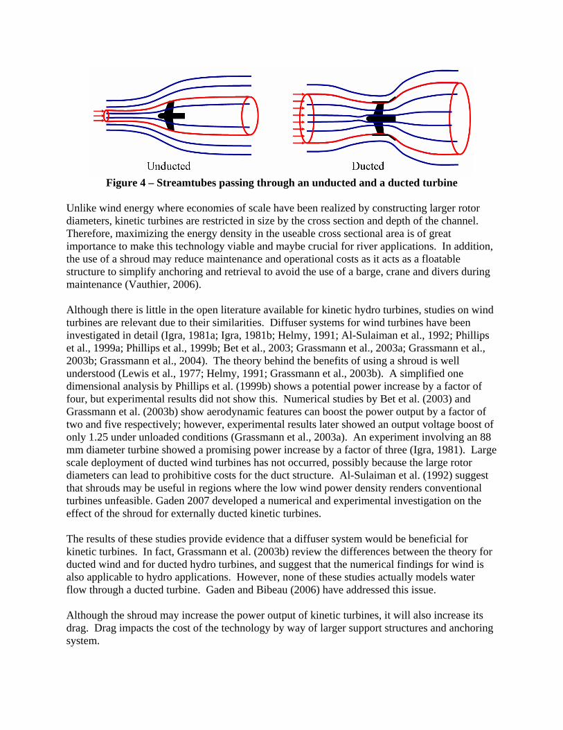
Figure 4 – Streamtubes passing through an unducted and a ducted turbine
Unlike wind energy where economies of scale have been realized by constructing larger rotor diameters, kinetic turbines are restricted in size by the cross section and depth of the channel. Therefore, maximizing the energy density in the useable cross sectional area is of great importance to make this technology viable and maybe crucial for river applications. In addition, the use of a shroud may reduce maintenance and operational costs as it acts as a floatable structure to simplify anchoring and retrieval to avoid the use of a barge, crane and divers during maintenance (Vauthier, 2006). Although there is little in the open literature available for kinetic hydro turbines, studies on wind turbines are relevant due to their similarities. Diffuser systems for wind turbines have been investigated in detail (Igra, 1981a; Igra, 1981b; Helmy, 1991; Al-Sulaiman et al., 1992; Phillips et al., 1999a; Phillips et al., 1999b; Bet et al., 2003; Grassmann et al., 2003a; Grassmann et al., 2003b; Grassmann et al., 2004). The theory behind the benefits of using a shroud is well understood (Lewis et al., 1977; Helmy, 1991; Grassmann et al., 2003b). A simplified one dimensional analysis by Phillips et al. (1999b) shows a potential power increase by a factor of four, but experimental results did not show this. Numerical studies by Bet et al. (2003) and Grassmann et al. (2003b) show aerodynamic features can boost the power output by a factor of two and five respectively; however, experimental results later showed an output voltage boost of only 1.25 under unloaded conditions (Grassmann et al., 2003a). An experiment involving an 88 mm diameter turbine showed a promising power increase by a factor of three (Igra, 1981). Large scale deployment of ducted wind turbines has not occurred, possibly because the large rotor diameters can lead to prohibitive costs for the duct structure. Al-Sulaiman et al. (1992) suggest that shrouds may be useful in regions where the low wind power density renders conventional turbines unfeasible. Gaden 2007 developed a numerical and experimental investigation on the effect of the shroud for externally ducted kinetic turbines. The results of these studies provide evidence that a diffuser system would be beneficial for kinetic turbines. In fact, Grassmann et al. (2003b) review the differences between the theory for ducted wind and for ducted hydro turbines, and suggest that the numerical findings for wind is also applicable to hydro applications. However, none of these studies actually models water flow through a ducted turbine. Gaden and Bibeau (2006) have addressed this issue. Although the shroud may increase the power output of kinetic turbines, it will also increase its drag. Drag impacts the cost of the technology by way of larger support structures and anchoring system.
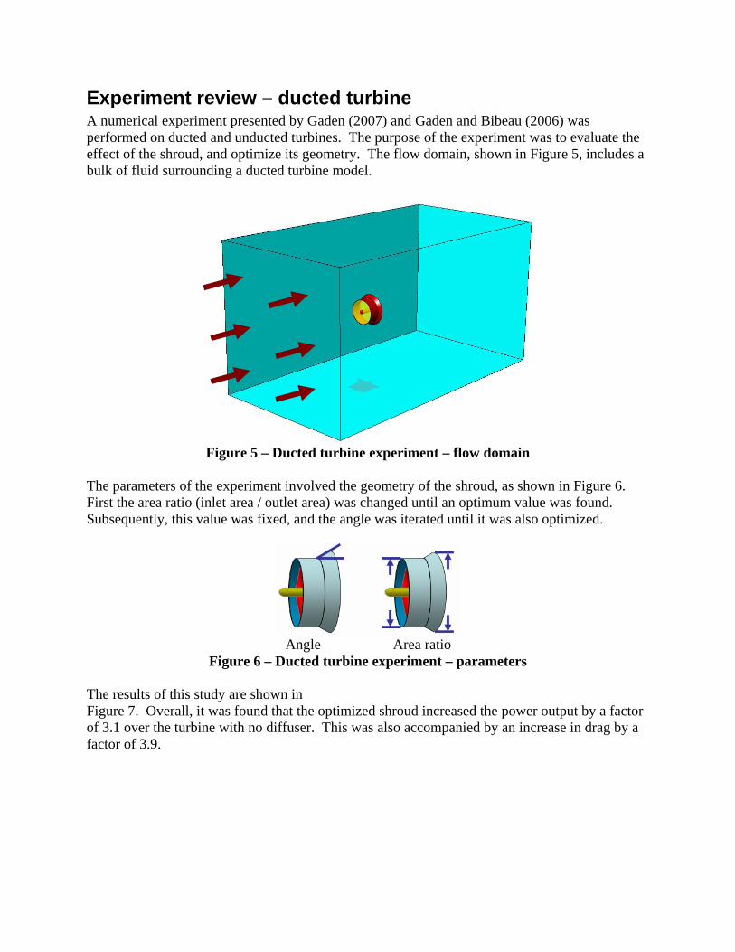
Experiment review – ducted turbine A numerical experiment presented by Gaden (2007) and Gaden and Bibeau (2006) was performed on ducted and unducted turbines. The purpose of the experiment was to evaluate the effect of the shroud, and optimize its geometry. The flow domain, shown in Figure 5, includes a bulk of fluid surrounding a ducted turbine model.
Figure 5 – Ducted turbine experiment – flow domain
The parameters of the experiment involved the geometry of the shroud, as shown in Figure 6. First the area ratio (inlet area / outlet area) was changed until an optimum value was found. Subsequently, this value was fixed, and the angle was iterated until it was also optimized.
Angle Area ratio
Figure 6 – Ducted turbine experiment – parameters The results of this study are shown in Figure 7. Overall, it was found that the optimized shroud increased the power output by a factor of 3.1 over the turbine with no diffuser. This was also accompanied by an increase in drag by a factor of 3.9.

0
10
20
30
40
50
60
0 1 2 3 4 5 6 7
Area ratio
Pow
er [k
W]
0
20
40
60
80
100
120
140
160
0 1 2 3 4 5 6 7
Area ratio
Dra
g [k
N]
a) Power versus area ratio b) Drag versus area ratio
0
10
20
30
40
50
60
0 10 20 30 40 50 60 7
Diffuser Angle [degrees]
Pow
er [k
W]
No diffuser case (shroud included)
0
0
5
10
15
20
25
30
35
0 10 20 30 40 50 60 70
Diffuser angle [°]
Dra
g [k
N]
Total dragShroud dragTurbine drag
No diffuser (shroud included)
c) Power versus diffuser angle d) Drag versus diffuser angle
Figure 7 – Ducted turbine experiment – results The relationship between area ratio and power output, seen in Figure 7 shows a sharp increase as the diffuser size increases, to a point where it levels off, which is expected due to separation. The drag responded almost linearly to area ratio. However, the diffuser angle had a more complicated relationship. Figure 8 shows the streamlines for the 20° and 45° diffusers. There is a significant recirculation region in the 45° case that is not present in the 20° case. The optimized diffuser angle most closely follows the streamlines as they exit the diffuser. Therefore it is likely that the optimum diffuser angle is a function of the freestream velocity. If this relationship can be determined, an adjustable diffuser can be developed that will make the turbine more versatile. This angle may be adjusted during maintenance, or even electronically controlled. It may be possible to construct the diffuser from a flexible material that will bend to the optimum angle, given the load conditions of the freestream. Debris in the river is a factor that must also be considered as this could damage the diffuser and add to the maintenance costs. The strength of the diffuser and its angle may cause it to be more susceptible to damage. A shallower angle is less likely to be exposed to strong impacts, especially when log collisions are expected.
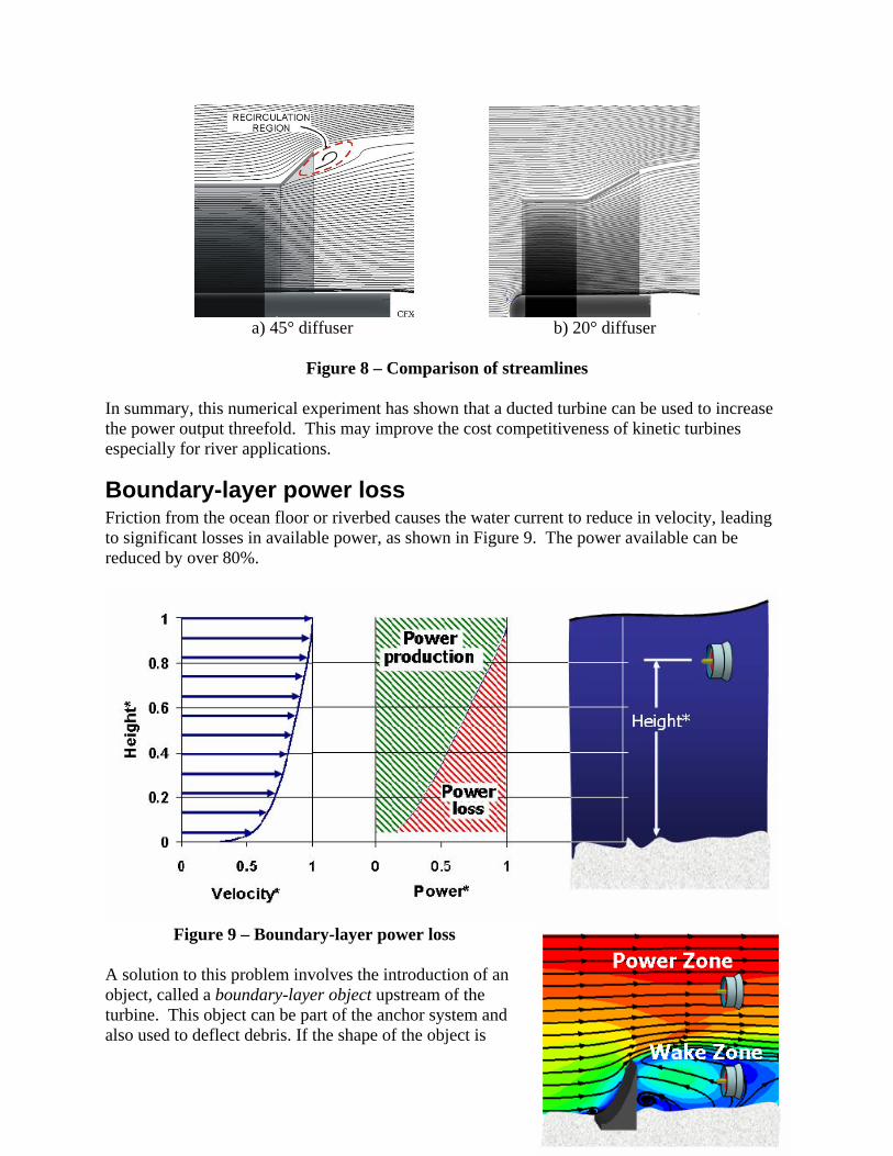
a) 45° diffuser b) 20° diffuser
Figure 8 – Comparison of streamlines In summary, this numerical experiment has shown that a ducted turbine can be used to increase the power output threefold. This may improve the cost competitiveness of kinetic turbines especially for river applications.
Boundary-layer power loss Friction from the ocean floor or riverbed causes the water current to reduce in velocity, leading to significant losses in available power, as shown in Figure 9. The power available can be reduced by over 80%.
Figure 9 – Boundary-layer power loss
A solution to this problem involves the introduction of an object, called a boundary-layer object upstream of the turbine. This object can be part of the anchor system and also used to deflect debris. If the shape of the object is
carefully selected, it may interrupt the boundary-layer and improve the conditions for the turbine. In fact, this object may be capable of addressing the two problems associated with external flow: low power density, and hazardous flow conditions. A numerical experiment is performed to evaluate if such an object is capable of:
• creating a power zone in which the power available to the kinetic turbine is increased; and
• creating a wake zone where the turbine is protected from damage.
Figure 10 – Boundary-layer object No previous studies could be found related to this concept (Figure 10). Submerged breakwaters are similar in geometry to boundary-layer objects; however they differ in application and therefore previous studies of submerged breakwaters are of little use to kinetic turbines. Existing studies for submerged breakwaters focus primarily on shore erosion (Ranasinghe et al. 2006), or on surface waves (Reddy et. al, 2007; Johnson, 2006; Johnson et. al, 2005; Stamos et. al, 2003), and sub-surface currents are not resolved in detail. Few studies exist that address the effects of the surrounding environment on kinetic turbines. Bahaj et al. (2003) provide an overview of the challenges facing kinetic turbines, with a focus on the marine environment. They discuss corrosion; marine growth; cavitation; and damage caused by debris as well as the large forces involved in a hydro environment. They highlight the importance of developing validated analytical models to further design efforts. Macleod et al. (2002) study the interactions between multiple kinetic turbines, as one would expect with large installations.
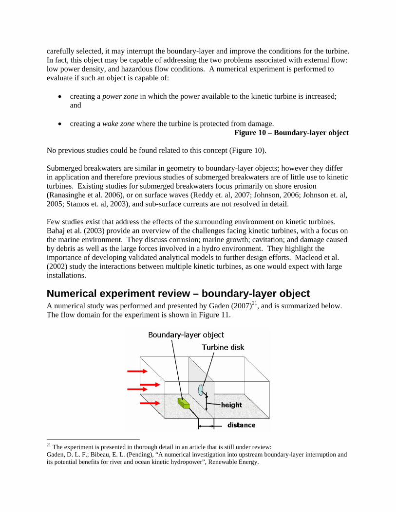
Numerical experiment review – boundary-layer object A numerical study was performed and presented by Gaden (2007)21, and is summarized below. The flow domain for the experiment is shown in Figure 11.
21 The experiment is presented in thorough detail in an article that is still under review: Gaden, D. L. F.; Bibeau, E. L. (Pending), “A numerical investigation into upstream boundary-layer interruption and its potential benefits for river and ocean kinetic hydropower”, Renewable Energy.

Figure 11 – Boundary-layer object experiment – flow domain The boundary-layer objects were designed qualitatively, as a broad overview of the effects of different design strategies. The six objects selected for study are shown in Figure 12. All objects have the same volume and footprint. The results are plotted in Figure 13, taken at a distance of 6 meters downstream from the object. The thick solid line shown in these figures represents the datum line – freestream flow with no boundary-layer object present. The power zones and wake zones can be seen in each profile. In all cases, the wake zones exist at the bottom of the fluid depth, and transition into power zones as height increases. The power zones exhibit simple, mostly linear profiles, whereas the wake zones exhibit more complex behaviours as one would expect in the presence of recirculation. Boundary-layer object D has the best performance, producing the strongest power zone, and the largest wake zone, followed by B and F. Objects A, C, and E all fared poorly.
Figure 12 – Boundary-layer objects

Figure 13 – Boundary-layer object experimental results
Although it is difficult to discern with the diversity of shapes in this study, two design aspects appear to play an important role in the performance of the boundary-layer objects: cross-stream area, and trailing edge geometry. Addressing cross-stream area first, with the exception of object E, the performance of each boundary-layer object correlated with its cross-stream area. A statistical analysis reveals a correlation of 87% between these variables. Treating object E as an outlier, the correlation improves to 98%, suggesting that a critical design criterion is to maximize cross-stream area. It may be advantageous to repeat this study holding cross-stream area constant rather than volume. In such a scenario, object A may wind up being the optimum shape as it produces the largest peak power per unit of cross-stream area. However, from a practical perspective, constant volume also represents a constant cost of material. Therefore these results are useful for maximizing performance against cost. Addressing the trailing edge geometry next, object E requires some attention. Despite its significant cross-stream area, this object had the lowest peak power, and the smallest wake zone. Unique to this object is the streamlined profile at the downstream edge. All other boundary-layer objects included sharp corners at the trailing edge, which results in highly separated, turbulent flow in the wake. Although the size of the wake has been treated as a performance measure, the ability of an object to produce a large wake is correlated with the power increases. A statistical analysis reveals that the correlation between the severity of the wake zone22 and the strength of
22 Wake zone severity was measured using a wake index which is the integral of the velocity defect (U - Udatum) over the height of the wake.

the power zone23 is 90.2%. This suggests that an important element of the boundary-layer object design is to ensure large wakes. This numerical experiment has shown that an object sitting upstream of the turbine can increase the power available to the turbine by over 15%. This same object can also create a protective zone up to 35% of the fluid depth into which the turbine can be moved during hazardous flow conditions and be used to anchor the turbine.
Conclusions Kinetic hydropower has many advantages that give it a clear foothold in the renewable energy market, and a recent surge in interest has been seen. Historic and recent kinetic hydropower developments have been reviewed. Challenges still remain, as kinetic turbines inherently involve external flow, and are therefore exposed to severe conditions. These external flow conditions are responsible for many of the disadvantages facing this technology, such as a low energy density, and hazardous flow conditions. Designing with these disadvantages in mind has given rise to some methods of addressing them. To increase the energy density, ducted turbines have been suggested and investigated. A review of a numerical experiment involving ducted turbines is given where it is found that the shroud can increase the power output threefold. A novel method is proposed that addresses both the low energy density and hazardous conditions of external flow. This method involves the introduction of an object, called a boundary-layer object, upstream of the turbine. A numerical investigation of these objects is reviewed. These boundary-layer objects are found to interfere with the existing boundary-layer of the ocean floor or riverbed. If their geometry is carefully selected, it is found that they can improve the conditions for the kinetic turbine. They work by creating a power zone in which the power available to the turbine is increased; and a wake zone into which the turbine can be moved during hazardous conditions. The best performing object achieved a power zone with a 15% power increase, and a wake zone that extended through 35% of the ocean or river depth.
References Al-Sulaiman, F. A.; Jamjoum, F. A. (1992). "Applications of wind power on the east coast of Saudi Arabia,” Renewable Energy, v. 2, n. 1, pp. 47-55. Bahaj, A. S.; Myers, L. E. (2003). "Fundamentals applicable to the utilisation of marine current turbines for energy production", Renewable Energy, v. 28. pp. 2205-2211. Bet, F.; Grassmann, H. (2003). "Upgrading conventional wind turbines,” Renewable Energy, v. 28, i. 1, pp. 71-78. Gaden, D. L. F. (2007), “An investigation of river kinetic turbines: performance enhancements, turbine modelling techniques, and an assessment of turbulence models”, M.Sc. Thesis, Department of Mechanical and Manufacturing Engineering, University of Manitoba.
23 Power zone strength was measured using a power index which is the integral of the velocity defect (U - Udatum) over the height of the power zone.

Gaden, D. L. F.; Bibeau, E. L. (2006). "Increasing power density of kinetic turbines for cost-effective distributed power generation,” POWER-GEN Renewable Energy Conference, Las Vegas, NV, April 10-12, 2006. Grassmann, H.; Bet, F.; Cabras, G.; Ceshia, M.; Cobai, D.; DelPapa, C. (2003). “A partially static turbine - first experimental results,” Technical note, Renewable Energy, v. 28, i. 11, pp. 1779-1785. Grassmann, H.; Bet, F.; Ceschia, M.; Ganis, M. L. (2003). “On the physics of partially static turbines,” Renewable Energy, v. 29, pp. 491-499. Grassmann, H.; Ganis, M. L. (2004). “On partially static Kaplan turbines,” Renewable Energy, v. 30, pp. 179-186. Helmy, M. L. (1991). “Dimensions of the axial flow turbine design for wind power,” Technical note, Renewable Energy, v. 1, n. 2, pp. 303-307. Igra, O. (1981). “Research and development for shrouded wind turbines,” Energy Conversion and Management, v. 21, pp. 13-48. Igra, O. (1981). “Shrouded wind turbine research in Israel,” International Journal of Ambient Energy, v. 2, pp. 85-96. Johnson, H. K. (2006). "Wave modelling in the vicinity of submerged breakwaters", Coastal Engineering, v. 53, pp. 39-48. Johnson, H. K.; Karambas, T. V.; Avergis, I.; Sanuttigh, B.; Gonzalez-Marco, D.; Caceres, I. (2005). "Modelling of waves and currents around submerged breakwaters", Coastal Engineering, v.52, pp. 949-969. Lewis, R. I.; Williams, J. E.; Adbelghaffar, M. A.; (1977). “A theory and experimental investigation of ducted wind turbines,” Wind Engineering, v. 1, pp. 104-125. Macleod, A. J.; Barnes, S.; Rados, K. G.; Bryden, I. G. (2002). "Wake effects in tidal current turbine farms", MAREC 2002, International Conference on Marine Renewable Energy - Conference Proceedings, pp. 49-53. Phillips, D. G.; Flay, R. G. J.; Nash, T. A. (1999). “Aerodynamic analysis and monitoring of the Vortec 7 diffuser-augmented wind turbine,” IPENZ Transactions, 1999, v. 26, n. 1. Phillips, D.G.; Nash, T. A.; Oakey, A.; Flay, R. G. J.; Richards, P. J. (1999). “Computational fluid dynamic and wind tunnel modelling of a diffuser augmented wind turbine,” Wind Engineering, v. 23, pp. 7-13. Ranasinghe, R.; Turner, I. L. (2006). "Shoreline response to submerged structures: A review", Coastal Engineering, v. 53, pp. 65-79.

Reddy, M. G. M.; Sannasiraj, S. A.; Natarajan, R. (2007). "Numerical investigation on the dynamics of a vertical wall defenced by an offshore breakwater", Ocean Engineering, v. 34, pp. 790-798. Segergren, E. (2005). “Direct drive generator for renewable power coversion from water currents”, Acta Universitatis Upsaliensis. Digital Comprehensive Summaries of Uppsala Dissertations from the Faculty of Science and Technology 100. pp. 1-44. Stamos, D. G.; Hajj, M. R.; Telionis, D. P. (2003). "Performance of hemi-cylindrical and rectangular submerged breakwaters", Ocean Engineering, v. 30, pp. 813-828. Vauthier, P. (2006). “Kite soars to new depths,” Water Power Magazine, 2006-03-16. Accessed 2007-01-09, available at http://www.waterpowermagazine.com/story.asp?sectionCode=46&storyCode=2034904