
Performance Enhancement in Sliding Vane Rotary Compressors ...
12
Purdue University Purdue e-Pubs International Compressor Engineering Conference School of Mechanical Engineering 2014 Performance Enhancement in Sliding Vane Rotary Compressors through a Sprayed Oil Injection Technology Giuseppe Bianchi University of L'Aquila, Italy, [email protected] Roberto Cipollone University of L'Aquila, Italy, [email protected] Stefano Murgia Ing. Enea Maei S.p.A., Vimodrone (Milan), Italy, [email protected] Giulio Contaldi Ing. Enea Maei S.p.A., Vimodrone (Milan), Italy, [email protected] Follow this and additional works at: hp://docs.lib.purdue.edu/icec is document has been made available through Purdue e-Pubs, a service of the Purdue University Libraries. Please contact [email protected] for additional information. Complete proceedings may be acquired in print and on CD-ROM directly from the Ray W. Herrick Laboratories at hps://engineering.purdue.edu/ Herrick/Events/orderlit.html Bianchi, Giuseppe; Cipollone, Roberto; Murgia, Stefano; and Contaldi, Giulio, "Performance Enhancement in Sliding Vane Rotary Compressors through a Sprayed Oil Injection Technology" (2014). International Compressor Engineering Conference. Paper 2378. hp://docs.lib.purdue.edu/icec/2378
Transcript of Performance Enhancement in Sliding Vane Rotary Compressors ...
Purdue UniversityPurdue e-Pubs
International Compressor Engineering Conference School of Mechanical Engineering
2014
Performance Enhancement in Sliding Vane RotaryCompressors through a Sprayed Oil InjectionTechnologyGiuseppe BianchiUniversity of L'Aquila, Italy, [email protected]
Roberto CipolloneUniversity of L'Aquila, Italy, [email protected]
Stefano MurgiaIng. Enea Mattei S.p.A., Vimodrone (Milan), Italy, [email protected]
Giulio ContaldiIng. Enea Mattei S.p.A., Vimodrone (Milan), Italy, [email protected]
Follow this and additional works at: http://docs.lib.purdue.edu/icec
This document has been made available through Purdue e-Pubs, a service of the Purdue University Libraries. Please contact [email protected] foradditional information.Complete proceedings may be acquired in print and on CD-ROM directly from the Ray W. Herrick Laboratories at https://engineering.purdue.edu/Herrick/Events/orderlit.html
Bianchi, Giuseppe; Cipollone, Roberto; Murgia, Stefano; and Contaldi, Giulio, "Performance Enhancement in Sliding Vane RotaryCompressors through a Sprayed Oil Injection Technology" (2014). International Compressor Engineering Conference. Paper 2378.http://docs.lib.purdue.edu/icec/2378
1651, Page 1
Performance Enhancement in Sliding Vane Rotary Compressors through aSprayed Oil Injection Technology
Giuseppe BIANCHI1†, Roberto CIPOLLONE1*, Stefano MURGIA2‡, Giulio CONTALDI2††
1 University of L'Aquila,Department of Industrial and Information Engineering and Economics,
L'Aquila, Italy†[email protected],
*[email protected], +39 0862 4343192 Ing. Enea Mattei S.p.A.,
Vimodrone, Italy‡ stefano [email protected],†† giulio [email protected]
* Corresponding Author
ABSTRACT
In Sliding Vane Rotary Compressors, as well as in most of positive displacement machines, the oil is injected toaccomplish sealing and lubrication purposes. However, the oil injection could produce an additional outcome duringthe compression phase with a great saving potential from the energetic point of view. Being the air inside the cellat a higher temperature than the oil injected, a cooling effect could be achieved so decreasing the mechanical powerrequired for the compression. At the moment, the oil is introduced inside the compressor vanes simply through a seriesof calibrated holes that are only able to produce solid jets. In this way any effective heat transfer is prevented, asdemonstrated by p-V measurements inside the cells during the compression phase.In the current study, a theoretical model of a sprayed oil injection technology was developed and further experimentallyvalidated. The oil was injected along the axial length of the compressor through a number of pressure swirl atomizerswhich produced a very fine spray. The conservation equations, solved with a Lagrangian approach, allowed to trackthe droplets evolution from the injection until the impingement onto the metallic surfaces of the vanes. The theoreticalapproach assessed the cooling effect due to the high surface to volume ratio of the droplets and a reduction of theindicated power was predicted. The model validation was carried out through a test campaign on an mid-size slidingvane compressor equipped with a series of pressure swirl injectors. The reconstruction of the indicator diagram aswell as the direct measurements of torque and revolution speed revealed a reduction of the mechanical power absorbedclose to 7% using an injection pressure of 20 bar. The model is in a satisfactory agreement with the tests and italso confirms the experimental trends available in the literature. A parametric analysis on the injection pressure andtemperature and on the cone spray angle was eventually carried out in order to identify an optimal set of operatinginjection parameters.
1. INTRODUCTION
Compressed air accounts for a mean 10 % of the global industrial electric energy consumptions (Radgen, 2001) andthis share may reach the 20 % if commercial and residential needs are included (portable tools, air pumps, pneumaticheating, ventilation, air conditioning, etc…) (US Department of Energy and Energy Efficiency and Renewable En-ergy, 2003). In order to accomplish the global energetic and environmental commitments, energy saving is nowadaysrecognized as the main action that needs to be put into action. Within this framework, in Compressed Air Systems(CAS) lots of saving measures have been employing with actions upstream and downstream of the compressed airproduction: pipeline leakages reduction, CAS design, adjustable speed drives, optimization of the end use devices,frictional losses, etc. As concerns the compressor technology, the saving potential was estimated to be around the10-20 % (740 TWh in 2012) (Cipollone and Vittorini, 2014). In industrial applications, rotary volumetric machines arethe most widespread technology in the range 7-12 bar and flow rates less than 1000 m3/min with an electrical power
22nd International Compressor Engineering Conference at Purdue, July 14-17, 2014
1651, Page 2
from a few kW to several hundred kW. Among them, Sliding Vane Rotary Compressors (SVRC) represent only fewpoints percent of the overall market. However, they have some intrinsic features which state an unforeseen poten-tial. Indeed, a recent study on the energy reduction perspectives in positive displacement machines stated that SVRCsbehave more efficiently than screw compressors if on/off load conditions were taken into account while estimatingthe energy consumptions (Cipollone, 2014). In order to additionally increase the premium performance of SVRCs, athermodynamic improvement was highlighted approaching the current adiabatic transformation towards an isothermalone by means of a sprayed oil injection technology that preliminary demonstrated its ability to internally cool the airduring the compression phase (Cipollone et al., 2012, 2013).The performance enhancement through a sprayed oil injection technology has been assessed almost exclusively onscrew compressors. Mathematical models on the heat transfer between oil droplets and air have been set up by Sesha-iah et al. (2007) and Stosic et al. (1988) as well as experimental activities on the sole atomizers (Paepe et al., 2005)or the whole compressor test rig have been carried out (Stošic et al., 1992; Fujiwara and Osada, 1995), even usingdifferent working fluids (Seshaiah et al., 2010). Among them, Stošic et al. (1992) stated a reduction on the energy con-sumptions from 2.8 % to 7.4 %. The roles of the main injection parameters have been investigated: injection pressureand temperature, oil flow rate, orifice diameter (Paepe et al., 2005), injectors positioning (Ferreira et al., 2006), etc.In the current work, the Authors pursued the investigation of the effects due to spraying the oil in sliding vane com-pressors presenting a comprehensive theoretical model for the axial injection. The model was further validated throughtests on a mid-size SVRC equipped with pressure swirl nozzles. A series of piezoelectric pressure transducers allowedto assess an overall matching between the simulations and the experimental indicator diagram (p-V). A parametric anal-ysis on the main injection operating parameters eventually addressed further improvements to the innovative injectiontechnology.
2. AXIAL OIL INJECTION MODELING
The oil sprayed injection was modeled following a lumped parameter approach for the thermodynamics inside thecompressor cells while the oil particles were tracked in a Lagrangian framework. The injectors are assumed to belocated on a side cover of the machine such that the oil droplets sprayed propagate along the axial direction of thecompressor. The model aims at understanding the interactions between oil sprays and the compressing air in order toidentify the optimal set of injection parameters to address the experimental activity. To ease the computations withoutlosing the physics behind the model, some assumptions were made: among them, a two dimensional approach was usedto detect the spray evolution within the rotating cells. Hence, for each injector at a given angular position, the frameof reference chosen for the study was the radial-axial plane. Furthermore, the way of subdividing the spray in dropletspackages having different injection angles also led to neglect secondary phenomena like the droplets coalescence. Theoverall structure of the model is composed of three main modules which deal with the spray formation, its interactionwith the air according to the conservation principles and its effects on the compression, respectively.
2.1 Spray formationUsing pressure-swirl atomizers and proper injection pressures, the oil jets breakup in a multitude of droplets havingdifferent sizes, as experimentally observed by Valenti et al. (2013). Experiments on the same nozzles by Laryea andNo (2004) found that the droplet size distribution resembles the Rosin Rammler function with a Sauter Mean Diameter(SMD) estimated according to the empirical correlation in Equation 1 proposed by Liu (1999).
SMD = 4.52⎛⎝σoμ2oρa Δp
⎞⎠
0.25⎡⎢⎢⎢⎢⎣2.7⎛⎝Dor mo μoρo Δp
⎞⎠cos γ⎤⎥⎥⎥⎥⎦
0.25
+ 0.39⎛⎝ρoμoρa Δp
⎞⎠
0.25⎡⎢⎢⎢⎢⎣2.7⎛⎝Dor mo μoρo Δp
⎞⎠cos γ⎤⎥⎥⎥⎥⎦
0.75
(1)
being γ the half the cone spray angle, Dor the orifice diameter and Δp the pressure difference across the nozzle. Thelatter parameter not only depends on the injection pressure but also on the injectors positioning: as they move towardsthe end of the compression phase, the air pressure increases and leads to smaller Δp, thus greater SMD.
The thermo-physical properties of the lubricant were evaluated using semi-empirical correlations (Conde, 1996; Mer-mond et al., 1999; Lottin et al., 2003) tuned with the experimental data from the oil manufacturer: specific gravity0.95, kinematic viscosity 99 cSt at 40○C and 10.2 cSt at 100○C.
22nd International Compressor Engineering Conference at Purdue, July 14-17, 2014
1651, Page 3
Spray Formation
Momentum Equation
Motioninside the cell
Impingement on the cell surfaces
Puddles
Heat Transfer (Convection, Evaporation)
Mass Exchange (Molecular Diffusion, Evaporation)
Thermodynamic Cell Model
(air + oil in liquid and vapour phases)
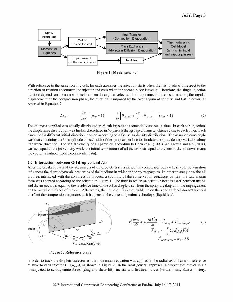
Figure 1: Model scheme
With reference to the same rotating cell, for each atomizer the injection starts when the first blade with respect to thedirection of rotation encounters the injector and ends when the second blade leaves it. Therefore, the single injectionduration depends on the number of cells and on the angular velocity. If multiple injectors are installed along the angulardisplacement of the compression phase, the duration is imposed by the overlapping of the first and last injectors, asreported in Equation 2
Δtinj ∶2πnω
(ninj = 1)1ω[θinj,last +
2πn− θinj,1st] (ninj > 1) (2)
The oil mass supplied was equally distributed in Nt sub-injections sequentially spaced in time. In each sub-injection,the droplet size distribution was further discretized inNd parcels that grouped diameter classes close to each other. Eachparcel had a different initial direction, chosen according to a Gaussian density distribution. The assumed cone anglewas that containing a ±3σ amplitude on each side of the spray center line to simulate the spray density variation alongtransverse direction. The initial velocity of all particles, according to Chen et al. (1993) and Laryea and No (2004),was set equal to the jet velocity while the initial temperature of all the droplets equal to the one of the oil downstreamthe cooler (available from experimental data).
2.2 Interaction between Oil droplets and AirAfter the breakup, each of the Nd parcels of oil droplets travels inside the compressor cells whose volume variationinfluences the thermodynamic properties of the medium in which the spray propagates. In order to study how the oildroplets interacted with the compression process, a coupling of the conservation equations written in a Lagrangianform was adopted according to the scheme in Figure 1. The time in which an effective heat transfer between the oiland the air occurs is equal to the residence time of the oil as droplets i.e. from the spray breakup until the impingementon the metallic surfaces of the cell. Afterwards, the liquid oil film that builds up on the vane surfaces doesn't succeedto affect the compression anymore, as it happens in the current injection technology (liquid jets).
Figure 2: Reference plane
Ð→Vddmd
dt+md
d(Ð→Vd)dt=Ð→F drag +
Ð→F centrifugal (3)Ð→F drag = −
π8Cd d2dρa(
Ð→Vd)2
Ð→F centrifugal = mdω2Ð→R
In order to track the droplets trajectories, the momentum equation was applied in the radial-axial frame of referencerelative to each injector (R,z,θinj,i), as shown in Figure 2. In the most general approach, a droplet that moves in airis subjected to aerodynamic forces (drag and shear lift), inertial and fictitious forces (virtual mass, Bassett history,
22nd International Compressor Engineering Conference at Purdue, July 14-17, 2014
1651, Page 4
centrifugal, Coriolis), volume forces (gravity and buoyancy) and pressure forces (Aggarwal and Peng, 1995). Withreference to previous studies, most of these contributions become negligible when compared with the drag, centrifugaland Coriolis forces (Cipollone et al., 2012; C.N. Brown, 1991). Moreover, since the droplets propagate along the R-z plane, the Coriolis force doesn't lie on the frame of reference but its perpendicular to it. However, its magnitudedepends on the angle between the droplet velocity and the angular velocity vector that cannot exceed the half of thecone spray angle. Due to the tightness of the gap between stator and rotor, for axial injections nozzles with narrowcone spray angles should be used to prevent that most of the spray would suddenly impinge on the cell surfaces. Inaccordance with this assumption, the effects of the Coriolis force on the droplets trajectories were neglected and thefinal expression for the momentum equation became the one reported in Equation 3, whereas the droplet evaporationwas taken into account in the term
Ð→Vd dmd/dt.As long as the droplets travel within the compressor cells, they exchange mass and heat with the air. Moreover,depending on the oil saturation pressure at the cell temperature, evaporation or even condensation might occur. Froman energetic point of view, the first phase change enhances the air cooling but, at the same time, provides oil vaporsthat need to be compressed as the air does so leading to an increase of the useful specific work per unit air. On the otherhand, if saturation conditions were established inside the cell, the oil vapors would condensate releasing the latent heatto the air with an increase of the compression work as well. Therefore, the target to reach with the sprayed injectiontechnology is to maximize the heat transfer between oil and air without reaching any oil phase change. The overallheat transfer between oil and air was modeled according to the energy equation for the droplet:
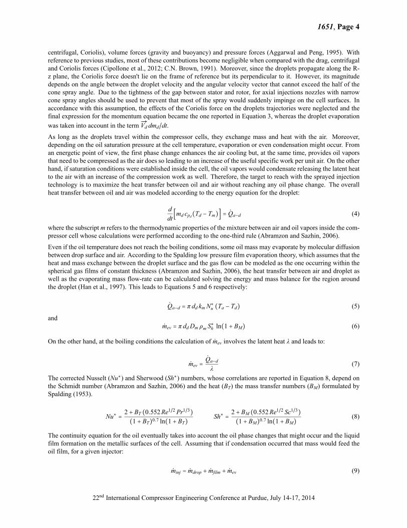
ddt[md cpd(Td − Tm)] = Qa−d (4)
where the subscriptm refers to the thermodynamic properties of the mixture between air and oil vapors inside the com-pressor cell whose calculations were performed according to the one-third rule (Abramzon and Sazhin, 2006).
Even if the oil temperature does not reach the boiling conditions, some oil mass may evaporate by molecular diffusionbetween drop surface and air. According to the Spalding low pressure film evaporation theory, which assumes that theheat and mass exchange between the droplet surface and the gas flow can be modeled as the one occurring within thespherical gas films of constant thickness (Abramzon and Sazhin, 2006), the heat transfer between air and droplet aswell as the evaporating mass flow-rate can be calculated solving the energy and mass balance for the region aroundthe droplet (Han et al., 1997). This leads to Equations 5 and 6 respectively:
Qa−d = π dd kmN∗u (Ta − Td) (5)
andmev = π ddDm ρm S
∗h ln(1 + BM) (6)
On the other hand, at the boiling conditions the calculation of mev involves the latent heat λ and leads to:
mev =Qa−d
λ(7)
The corrected Nusselt (Nu∗) and Sherwood (Sh∗) numbers, whose correlations are reported in Equation 8, depend onthe Schmidt number (Abramzon and Sazhin, 2006) and the heat (BT) the mass transfer numbers (BM) formulated bySpalding (1953).
Nu∗ = 2 + BT (0.552Re1/2 Pr1/3)(1 + BT)0.7 ln(1 + BT)
Sh∗ = 2 + BM (0.552Re1/2 Sc1/3)(1 + BM)0.7 ln(1 + BM)
(8)
The continuity equation for the oil eventually takes into account the oil phase changes that might occur and the liquidfilm formation on the metallic surfaces of the cell. Assuming that if condensation occurred that mass would feed theoil film, for a given injector:
minj = mdrop + mfilm + mev (9)
22nd International Compressor Engineering Conference at Purdue, July 14-17, 2014
1651, Page 5
In the present application, being the volatility as well as mass diffusivity of the oil used very low and the dimensionsof the droplets atomized not enough small to vaporize, the latter contribution assumes a secondary influence. Hence,the overall heat transfer is driven by the forced convection between oil droplets and air.
2.3 Cell thermodynamicsAt the moment, the oil injection in sliding vane compressors, as well as in other volumetric machines, accomplisheslubrication and sealing purposes. This latter feature prevents flow leakages between adjacent cells, and through theside covers of the machine. Assuming a perfect sealing, the cell behaves as a closed system with respect to the airthat is trapped at the suction end, compressed and eventually discharged. As concerns the gaseous fluids in the vane,the only mass transfers that may occur are the droplets evaporation (positive) or their condensation (negative). Hence,the working fluid inside the cell is a mixture of air and oil vapors that are assumed to behave as a mixture of idealgases. Furthermore, the cell thermodynamics was investigated with a lumped parameter approach that led to uniformthermodynamic properties (pressure, temperature, composition etc.). The cell pressure was calculated solving the firstderivative of the equation of state. On the other hand, the temperature evolution inside the cell was evaluated accordingto the first law of the thermodynamics neglecting secondary heat transfer phenomena as the one between the air andthe oil film whose topology is continuously modified by the blade sliding within the rotor slots and at the contact pointbetween the tip and the inner surface of the stator. Both the quantities involve the condensation flow rate and latentheat. This phase change occurs if the oil vapor mass exceeds the saturation mass at the cell temperature (Cipolloneet al., 2012).
3. EXPERIMENTAL VALIDATION
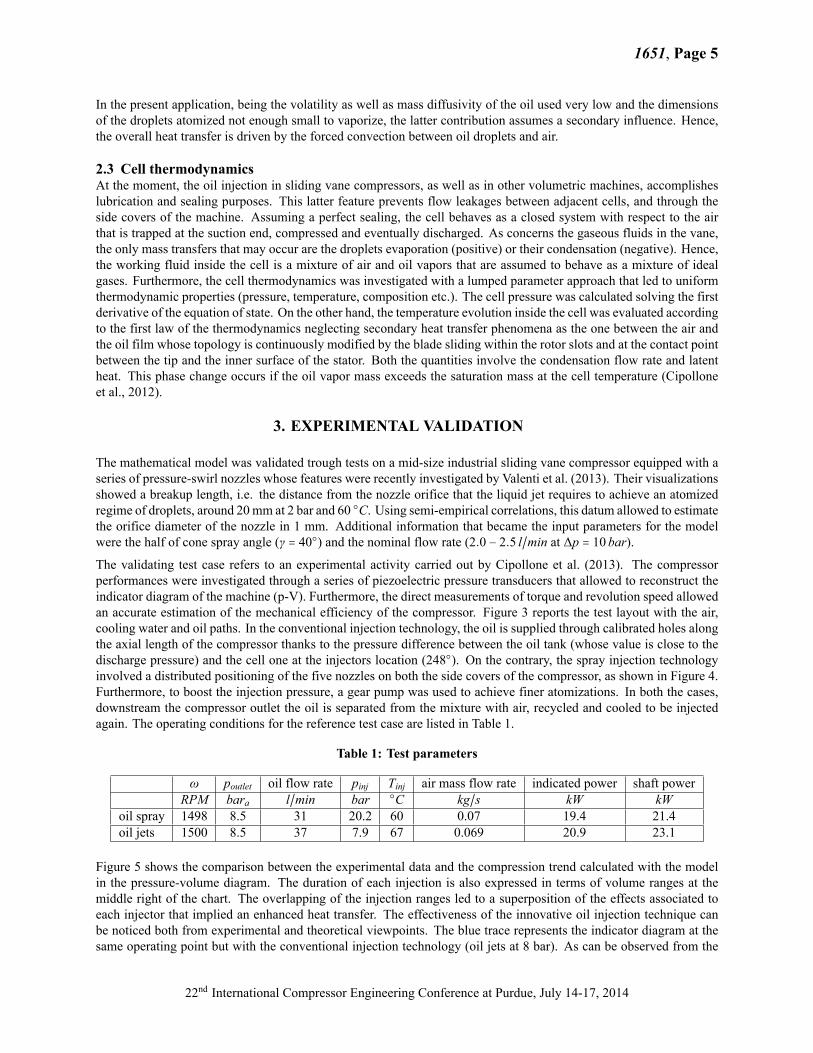
The mathematical model was validated trough tests on a mid-size industrial sliding vane compressor equipped with aseries of pressure-swirl nozzles whose features were recently investigated by Valenti et al. (2013). Their visualizationsshowed a breakup length, i.e. the distance from the nozzle orifice that the liquid jet requires to achieve an atomizedregime of droplets, around 20mm at 2 bar and 60 ○C. Using semi-empirical correlations, this datum allowed to estimatethe orifice diameter of the nozzle in 1 mm. Additional information that became the input parameters for the modelwere the half of cone spray angle (γ = 40○) and the nominal flow rate (2.0 − 2.5 l/min at Δp = 10bar).The validating test case refers to an experimental activity carried out by Cipollone et al. (2013). The compressorperformances were investigated through a series of piezoelectric pressure transducers that allowed to reconstruct theindicator diagram of the machine (p-V). Furthermore, the direct measurements of torque and revolution speed allowedan accurate estimation of the mechanical efficiency of the compressor. Figure 3 reports the test layout with the air,cooling water and oil paths. In the conventional injection technology, the oil is supplied through calibrated holes alongthe axial length of the compressor thanks to the pressure difference between the oil tank (whose value is close to thedischarge pressure) and the cell one at the injectors location (248○). On the contrary, the spray injection technologyinvolved a distributed positioning of the five nozzles on both the side covers of the compressor, as shown in Figure 4.Furthermore, to boost the injection pressure, a gear pump was used to achieve finer atomizations. In both the cases,downstream the compressor outlet the oil is separated from the mixture with air, recycled and cooled to be injectedagain. The operating conditions for the reference test case are listed in Table 1.
Table 1: Test parameters
ω poutlet oil flow rate pinj Tinj air mass flow rate indicated power shaft powerRPM bara l/min bar ○C kg/s kW kW
oil spray 1498 8.5 31 20.2 60 0.07 19.4 21.4oil jets 1500 8.5 37 7.9 67 0.069 20.9 23.1
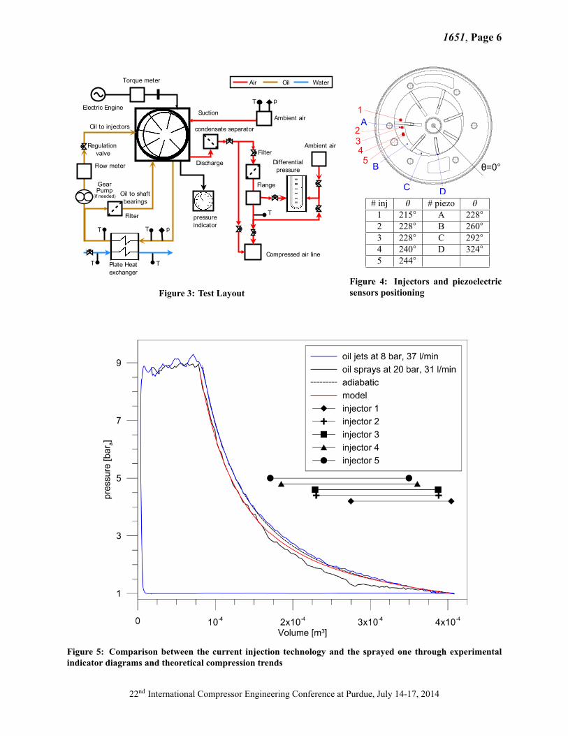
Figure 5 shows the comparison between the experimental data and the compression trend calculated with the modelin the pressure-volume diagram. The duration of each injection is also expressed in terms of volume ranges at themiddle right of the chart. The overlapping of the injection ranges led to a superposition of the effects associated toeach injector that implied an enhanced heat transfer. The effectiveness of the innovative oil injection technique canbe noticed both from experimental and theoretical viewpoints. The blue trace represents the indicator diagram at thesame operating point but with the conventional injection technology (oil jets at 8 bar). As can be observed from the
22nd International Compressor Engineering Conference at Purdue, July 14-17, 2014
1651, Page 6
Figure 3: Test Layout
# inj θ # piezo θ1 215○ A 228○2 228○ B 260○3 228○ C 292○4 240○ D 324○5 244○
Figure 4: Injectors and piezoelectricsensors positioning
Figure 5: Comparison between the current injection technology and the sprayed one through experimentalindicator diagrams and theoretical compression trends
22nd International Compressor Engineering Conference at Purdue, July 14-17, 2014
1651, Page 7
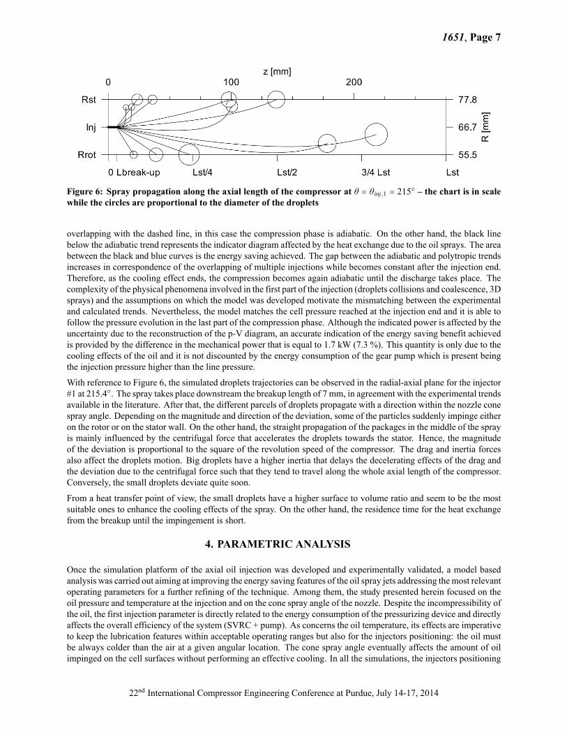
Figure 6: Spray propagation along the axial length of the compressor at θ = θinj,1 = 215○ – the chart is in scalewhile the circles are proportional to the diameter of the droplets
overlapping with the dashed line, in this case the compression phase is adiabatic. On the other hand, the black linebelow the adiabatic trend represents the indicator diagram affected by the heat exchange due to the oil sprays. The areabetween the black and blue curves is the energy saving achieved. The gap between the adiabatic and polytropic trendsincreases in correspondence of the overlapping of multiple injections while becomes constant after the injection end.Therefore, as the cooling effect ends, the compression becomes again adiabatic until the discharge takes place. Thecomplexity of the physical phenomena involved in the first part of the injection (droplets collisions and coalescence, 3Dsprays) and the assumptions on which the model was developed motivate the mismatching between the experimentaland calculated trends. Nevertheless, the model matches the cell pressure reached at the injection end and it is able tofollow the pressure evolution in the last part of the compression phase. Although the indicated power is affected by theuncertainty due to the reconstruction of the p-V diagram, an accurate indication of the energy saving benefit achievedis provided by the difference in the mechanical power that is equal to 1.7 kW (7.3 %). This quantity is only due to thecooling effects of the oil and it is not discounted by the energy consumption of the gear pump which is present beingthe injection pressure higher than the line pressure.
With reference to Figure 6, the simulated droplets trajectories can be observed in the radial-axial plane for the injector#1 at 215.4○. The spray takes place downstream the breakup length of 7 mm, in agreement with the experimental trendsavailable in the literature. After that, the different parcels of droplets propagate with a direction within the nozzle conespray angle. Depending on the magnitude and direction of the deviation, some of the particles suddenly impinge eitheron the rotor or on the stator wall. On the other hand, the straight propagation of the packages in the middle of the sprayis mainly influenced by the centrifugal force that accelerates the droplets towards the stator. Hence, the magnitudeof the deviation is proportional to the square of the revolution speed of the compressor. The drag and inertia forcesalso affect the droplets motion. Big droplets have a higher inertia that delays the decelerating effects of the drag andthe deviation due to the centrifugal force such that they tend to travel along the whole axial length of the compressor.Conversely, the small droplets deviate quite soon.
From a heat transfer point of view, the small droplets have a higher surface to volume ratio and seem to be the mostsuitable ones to enhance the cooling effects of the spray. On the other hand, the residence time for the heat exchangefrom the breakup until the impingement is short.
4. PARAMETRIC ANALYSIS
Once the simulation platform of the axial oil injection was developed and experimentally validated, a model basedanalysis was carried out aiming at improving the energy saving features of the oil spray jets addressing themost relevantoperating parameters for a further refining of the technique. Among them, the study presented herein focused on theoil pressure and temperature at the injection and on the cone spray angle of the nozzle. Despite the incompressibility ofthe oil, the first injection parameter is directly related to the energy consumption of the pressurizing device and directlyaffects the overall efficiency of the system (SVRC + pump). As concerns the oil temperature, its effects are imperativeto keep the lubrication features within acceptable operating ranges but also for the injectors positioning: the oil mustbe always colder than the air at a given angular location. The cone spray angle eventually affects the amount of oilimpinged on the cell surfaces without performing an effective cooling. In all the simulations, the injectors positioning
22nd International Compressor Engineering Conference at Purdue, July 14-17, 2014
1651, Page 8
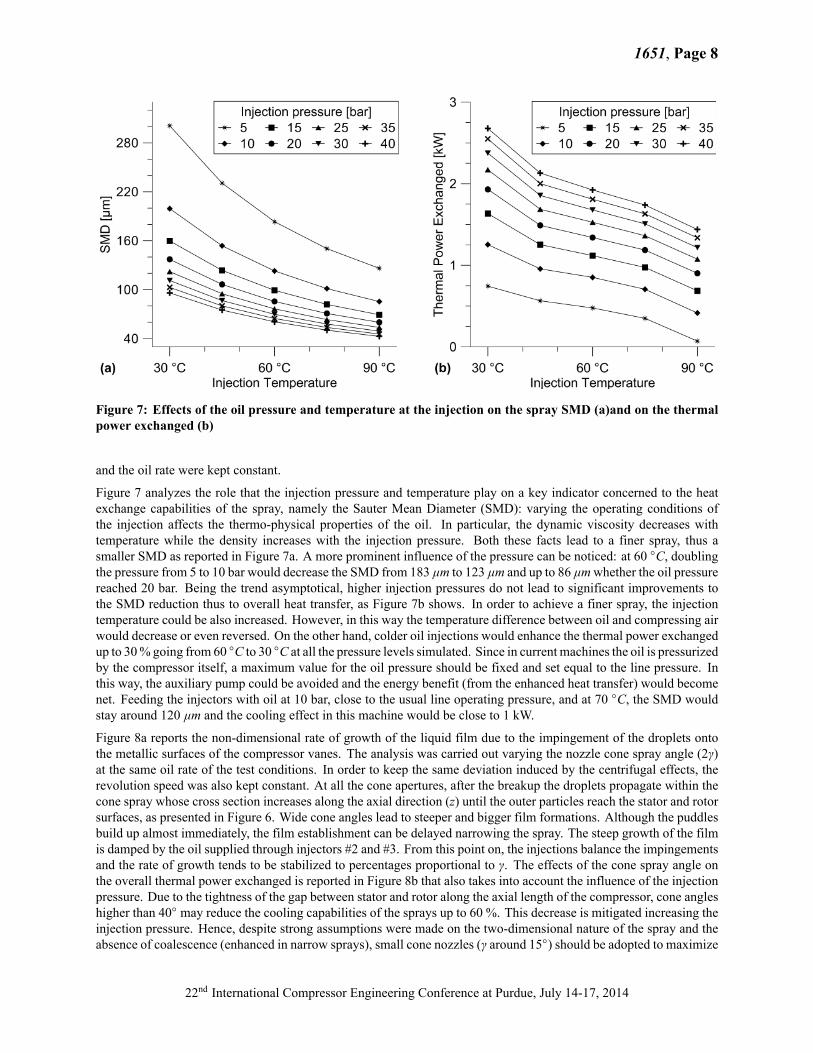
Figure 7: Effects of the oil pressure and temperature at the injection on the spray SMD (a)and on the thermalpower exchanged (b)
and the oil rate were kept constant.
Figure 7 analyzes the role that the injection pressure and temperature play on a key indicator concerned to the heatexchange capabilities of the spray, namely the Sauter Mean Diameter (SMD): varying the operating conditions ofthe injection affects the thermo-physical properties of the oil. In particular, the dynamic viscosity decreases withtemperature while the density increases with the injection pressure. Both these facts lead to a finer spray, thus asmaller SMD as reported in Figure 7a. A more prominent influence of the pressure can be noticed: at 60 ○C, doublingthe pressure from 5 to 10 bar would decrease the SMD from 183 μm to 123 μm and up to 86 μmwhether the oil pressurereached 20 bar. Being the trend asymptotical, higher injection pressures do not lead to significant improvements tothe SMD reduction thus to overall heat transfer, as Figure 7b shows. In order to achieve a finer spray, the injectiontemperature could be also increased. However, in this way the temperature difference between oil and compressing airwould decrease or even reversed. On the other hand, colder oil injections would enhance the thermal power exchangedup to 30% going from 60 ○C to 30 ○C at all the pressure levels simulated. Since in current machines the oil is pressurizedby the compressor itself, a maximum value for the oil pressure should be fixed and set equal to the line pressure. Inthis way, the auxiliary pump could be avoided and the energy benefit (from the enhanced heat transfer) would becomenet. Feeding the injectors with oil at 10 bar, close to the usual line operating pressure, and at 70 ○C, the SMD wouldstay around 120 μm and the cooling effect in this machine would be close to 1 kW.
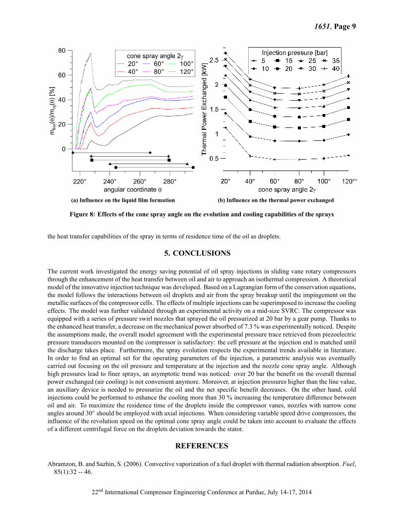
Figure 8a reports the non-dimensional rate of growth of the liquid film due to the impingement of the droplets ontothe metallic surfaces of the compressor vanes. The analysis was carried out varying the nozzle cone spray angle (2γ)at the same oil rate of the test conditions. In order to keep the same deviation induced by the centrifugal effects, therevolution speed was also kept constant. At all the cone apertures, after the breakup the droplets propagate within thecone spray whose cross section increases along the axial direction (z) until the outer particles reach the stator and rotorsurfaces, as presented in Figure 6. Wide cone angles lead to steeper and bigger film formations. Although the puddlesbuild up almost immediately, the film establishment can be delayed narrowing the spray. The steep growth of the filmis damped by the oil supplied through injectors #2 and #3. From this point on, the injections balance the impingementsand the rate of growth tends to be stabilized to percentages proportional to γ. The effects of the cone spray angle onthe overall thermal power exchanged is reported in Figure 8b that also takes into account the influence of the injectionpressure. Due to the tightness of the gap between stator and rotor along the axial length of the compressor, cone angleshigher than 40○ may reduce the cooling capabilities of the sprays up to 60 %. This decrease is mitigated increasing theinjection pressure. Hence, despite strong assumptions were made on the two-dimensional nature of the spray and theabsence of coalescence (enhanced in narrow sprays), small cone nozzles (γ around 15○) should be adopted to maximize
22nd International Compressor Engineering Conference at Purdue, July 14-17, 2014
1651, Page 9
(a) Influence on the liquid film formation (b) Influence on the thermal power exchanged
Figure 8: Effects of the cone spray angle on the evolution and cooling capabilities of the sprays
the heat transfer capabilities of the spray in terms of residence time of the oil as droplets.
5. CONCLUSIONS
The current work investigated the energy saving potential of oil spray injections in sliding vane rotary compressorsthrough the enhancement of the heat transfer between oil and air to approach an isothermal compression. A theoreticalmodel of the innovative injection technique was developed. Based on a Lagrangian form of the conservation equations,the model follows the interactions between oil droplets and air from the spray breakup until the impingement on themetallic surfaces of the compressor cells. The effects of multiple injections can be superimposed to increase the coolingeffects. The model was further validated through an experimental activity on a mid-size SVRC. The compressor wasequipped with a series of pressure swirl nozzles that sprayed the oil pressurized at 20 bar by a gear pump. Thanks tothe enhanced heat transfer, a decrease on the mechanical power absorbed of 7.3 %was experimentally noticed. Despitethe assumptions made, the overall model agreement with the experimental pressure trace retrieved from piezoelectricpressure transducers mounted on the compressor is satisfactory: the cell pressure at the injection end is matched untilthe discharge takes place. Furthermore, the spray evolution respects the experimental trends available in literature.In order to find an optimal set for the operating parameters of the injection, a parametric analysis was eventuallycarried out focusing on the oil pressure and temperature at the injection and the nozzle cone spray angle. Althoughhigh pressures lead to finer sprays, an asymptotic trend was noticed: over 20 bar the benefit on the overall thermalpower exchanged (air cooling) is not convenient anymore. Moreover, at injection pressures higher than the line value,an auxiliary device is needed to pressurize the oil and the net specific benefit decreases. On the other hand, coldinjections could be performed to enhance the cooling more than 30 % increasing the temperature difference betweenoil and air. To maximize the residence time of the droplets inside the compressor vanes, nozzles with narrow coneangles around 30○ should be employed with axial injections. When considering variable speed drive compressors, theinfluence of the revolution speed on the optimal cone spray angle could be taken into account to evaluate the effectsof a different centrifugal force on the droplets deviation towards the stator.
REFERENCES
Abramzon, B. and Sazhin, S. (2006). Convective vaporization of a fuel droplet with thermal radiation absorption. Fuel,85(1):32 -- 46.
22nd International Compressor Engineering Conference at Purdue, July 14-17, 2014
1651, Page 10
Aggarwal, S. K. and Peng, F. (1995). A review of droplet dynamics and vaporization modeling for engineering calcu-lations. Journal of Engineering for Gas Turbines and Power, 117(3):453--461.
Chen, J. L., Chen, G., and Wells, M. (1993). Dynamic and static flow analysis of a gasoline fuel injector. Journal ofEngineering for Gas Turbines and Power, 115(4):750--755.
Cipollone, R. (2014). Sliding vane rotary compressor technology and energy saving. Proceedings of the Institution ofMechanical Engineers, Part E: Journal of Process Mechanical Engineering.
Cipollone, R., Bianchi, G., andContaldi, G. (2012). Sliding vane rotary compressor energy optimization. InASME2012International Mechanical Engineering Congress and Exposition, pages 69--80. American Society of MechanicalEngineers.
Cipollone, R., Valenti, G., and Bianchi, G. e. a. (2013). Energy saving in sliding vane rotary compressors. In Proceed-ings of 8th International Conference on Compressors and their Systems, pages 173--182. Institution of MechanicalEngineers.
Cipollone, R. and Vittorini, D. (2014). Energy saving potential in existing compressors. In Proceedings of the 22ndInternational Compressor Engineering Conference. Purdue University.
C.N. Brown, N. L. (1991). A numerical study of fuel evaporation and transportation in the intake manifold of a port-injected spark-ignition engine. Journal of Automobile Engineering, 205(3):161--175.
Conde, M. R. (1996). Estimation of thermophysical properties of lubricating oils and their solutions with refrigerants:An appraisal of existing methods. Applied Thermal Engineering, 16(1):51 -- 61.
Ferreira, C. I., Zamfirescu, C., and Zaytsev, D. (2006). Twin screw oil-free wet compressor for compression–absorptioncycle. International Journal of Refrigeration, 29(4):556 -- 565.
Fujiwara, M. and Osada, Y. (1995). Performance analysis of an oil-injected screw compressor and its application.International Journal of Refrigeration, 18(4):220 -- 227.
Han, Z., Parrish, S., Farrell, P. V., and Reitz, R. D. (1997). Modeling atomization processes of pressure-swirl hollow-cone fuel sprays. Atomization and Sprays, 7(6):663--684.
Laryea, G. and No, S. (2004). Spray angle and breakup length of charge-injected electrostatic pressure-swirl nozzle.Journal of Electrostatics, 60(1):37 -- 47.
Liu, H. (1999). 4 - empirical and analytical correlations of droplet properties. In Science and Engineering of Droplets,pages 238 -- 314. William Andrew Publishing, Norwich, NY.
Lottin, O., Guillemet, P., and Lebreton, J.-M. (2003). Effects of synthetic oil in a compression refrigeration systemusing r410a. part i: modelling of the whole system and analysis of its response to an increase in the amount ofcirculating oil. International Journal of Refrigeration, 26(7):772 -- 782.
Mermond, Y., Feidt, M., and Marvillet, C. (1999). Thermodynamic and physical properties of mixtures of refrigerantsand oils. International Journal of Refrigeration, 22(7):569 -- 579.
Paepe, M. D., Bogaert, W., and Mertens, D. (2005). Cooling of oil injected screw compressors by oil atomisation.Applied Thermal Engineering, 25(17–18):2764 -- 2779.
Radgen, P. (2001). Compressed air systems in the European Union: energy, emissions, savings potential and policyactions. LOG_X Verlag GmbH.
Seshaiah, N., Ghosh, S. K., Sahoo, R., and Sarangi, S. K. (2007). Mathematical modeling of the working cycle of oilinjected rotary twin screw compressor. Applied Thermal Engineering, 27(1):145 -- 155.
Seshaiah, N., Sahoo, R., and Sarangi, S. (2010). Theoretical and experimental studies on oil injected twin-screw aircompressor when compressing different light and heavy gases. Applied Thermal Engineering, 30(4):327 -- 339.
Spalding, D. B. (1953). The combustion of liquid fuels. In Symposium (international) on combustion, volume 4, pages847--864. Elsevier.
Stošic, N., Milutinović, L., Hanjalić, K., and Kovačević, A. (1992). Investigation of the influence of oil injection uponthe screw compressor working process. International Journal of Refrigeration, 15(4):206 -- 220.
Stosic, N., Kovacevic, A., Hanjalic, K., and Milutinovic, L. (1988). Mathematical modelling of the oil influence uponthe working cycle of screw compressors. In Proceedings of the International Compressor Engineering Conference.Purdue University.
US Department of Energy and Energy Efficiency and Renewable Energy (2003). Improving Compressed Air SystemPerformance: a sourcebook for industry.
Valenti, G., Colombo, L., Murgia, S., Lucchini, A., Sampietro, A., Capoferri, A., and Araneo, L. (2013). Thermaleffect of lubricating oil in positive-displacement air compressors. Applied Thermal Engineering, 51(1–2):1055 --
22nd International Compressor Engineering Conference at Purdue, July 14-17, 2014
1651, Page 11
1066.
NOMENCLATURE
θ angular coordinate (deg) μ dynamic viscosity (Pa ⋅ s) F force (N)n number of cells (–) σ surface tension (N/m) Subscriptsω angular speed (rad/s) k thermal conductivity (W/m/K) a airp pressure (Pa) cp specific heat at const. p (J/kg/K) o oilT temperature (K) Q thermal power (W) m air-oil vapor mixturem mass (kg) d droplet diameter (m) ev evaporationm mass flow rate (kg/s) Cd drag coefficient (–) d dropletρ density (kg/m3) V droplet velocity (m/s) inj injection
22nd International Compressor Engineering Conference at Purdue, July 14-17, 2014