

Performance Based Analysis of Bridge Deck For … · Performance Based Analysis of Bridge Deck For...
5
Performance Based Analysis of Bridge Deck For Distinctive Girder Types Prateek S. Hundekar. Department of Civil Engineering, Shri Dharmasthala Manjunatheshwar College of Engineering and Technology, Dharwad, Karnataka, India. Dr. Dilip K. Kulkarni. Professor, Department of Civil Engineering, Shri Dharmasthala Manjunatheshwar College of Engineering and Technology, Dharwad, Karnataka, India. Abstract - Bridge decks must withstand one of the most damaging types of live load forces i.e. vehicle loads. In this research work, the bridge deck is modeled as a simply supported beam with the bridge deck slab spanning in one direction. Analysis for discrete model is done using the finite element method. This Thesis presents the results related to finite element analysis (FEA) of simply supported reinforced concrete bridge deck of different deck thicknesses (375mm to 825mm) and constant width of 12 m, without footpath under Indian Road Congress (IRC) vehicle load classes. Hence, a total of 128 numbers of cases were analyzed. The Dimension of deck slabs are taken from standard drawings of the Ministry of Road Transport & Highways-1991. And the deck was supported by four distinct types of girders for IRC Class 70R and IRC Class AA loading. The study indicates that the thickness of deck slab contributes a major role in carrying the vehicle loads. The increase in thickness reduces the loss in ultimate Moment carrying capacity; decrease the maximum deck stress and live load deflection; helps distribute deck live loads more evenly to the girders and increases the deck service life. Keywords—Concrete bridge deck slabs; Highway; Finite element analysis; Simply supported; Vehicle load classes. I. INTRODUCTION Bridge decks must withstand one of the most damaging types of live load forces i.e., the concentrated and direct pounding of truck wheels. A primary function of the deck is to distribute these forces in a favorable manner to the support elements below. The ratio of live to total load stresses is high in bridge decks usually much higher than in most of the other components of the bridge. The bridge deck is modeled as a simply supported beam (Fig 1) or multi-span continuous beam, and the vehicle/bridge interaction force is modeled as one-point or two-point loads at a fixed spacing moving at a constant speed. In India, in the case of bridge deck slabs spanning in one direction, the bending moment per unit width of slab caused by the IRC vehicle loads can be calculated by estimating the width of slab that may be taken as effective in resisting the bending moment due to the loads (Fig 2) and accordingly the deck slab is designed for that bending moment. The dynamic performance of bridges can be affected by many factors. Different types of vehicles, vehicle speeds, and road surface conditions could all contribute to different bridge dynamic performances. The effects of heavily loaded trucks can be determinant for the evaluation of deck slabs. Fig.1 simply supported beam Fig.2. Sectional Forces And Stresses Of A Finite Plate Element II. METHODOLOGY The identification and analyses of the bridge deck is done for various types of loads and load classes, mainly live loads and self-weight of the structure. The modeling is carried out by using a standard FEA package which helps in proper modeling and accurate analysis of the bridge deck for various parameters of loads, loading types and type of structural elements supporting the deck. A virtual model of the bridge deck system is created using the software to obtain results for forces, displacements, bending moments etc. The virtual model can be simulated and modified for the application of various load classes and different girder supports, and are used further for the purpose of analysis. International Journal of Engineering Research & Technology (IJERT) Vol. 3 Issue 8, August - 2014 ISSN: 2278-0181 www.ijert.org IJERTV3IS080712 (This work is licensed under a Creative Commons Attribution 4.0 International License.) 694
Transcript of Performance Based Analysis of Bridge Deck For … · Performance Based Analysis of Bridge Deck For...
Performance Based Analysis of Bridge Deck For
Distinctive Girder Types
Prateek S. Hundekar.
Department of Civil Engineering,
Shri Dharmasthala Manjunatheshwar College of
Engineering and Technology,
Dharwad, Karnataka, India.
Dr.
Dilip K. Kulkarni.
Professor,
Department
of Civil Engineering,
Shri Dharmasthala Manjunatheshwar College of
Engineering and Technology,
Dharwad, Karnataka, India.
Abstract - Bridge decks must withstand one of the most
damaging types of live load forces i.e. vehicle loads. In this
research work, the bridge deck is modeled as a simply
supported beam with the bridge deck slab spanning in one
direction. Analysis for discrete model is done using the finite
element method. This Thesis presents the results related to
finite element analysis (FEA) of simply supported reinforced
concrete bridge deck of different deck thicknesses (375mm to
825mm) and constant width of 12 m, without footpath under
Indian Road Congress (IRC) vehicle load classes. Hence, a
total of 128 numbers of cases were analyzed. The Dimension
of deck slabs are taken from standard drawings of the
Ministry of Road Transport & Highways-1991. And the deck
was supported by four distinct types of girders for IRC Class
70R and IRC Class AA loading. The study indicates that the
thickness of deck slab contributes a major role in carrying the
vehicle loads. The increase in thickness reduces the loss in
ultimate Moment carrying capacity; decrease the maximum
deck stress and live load deflection; helps distribute deck live
loads more evenly to the girders and increases the deck
service life.
Keywords—Concrete bridge deck slabs; Highway; Finite
element analysis; Simply supported; Vehicle load classes.
I. INTRODUCTION
Bridge decks must withstand one of the most
damaging types of live load forces i.e., the concentrated
and direct pounding of truck wheels. A primary function of
the deck is to distribute these forces in a favorable manner
to the support elements below. The ratio of live to total
load stresses is high in bridge decks usually much higher
than in most of the other components of the bridge.
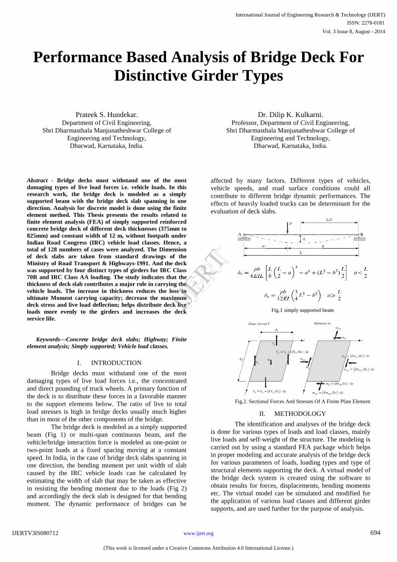
The bridge deck is modeled as a simply supported
beam (Fig 1) or multi-span continuous beam, and the
vehicle/bridge interaction force is modeled as one-point or
two-point loads at a fixed spacing moving at a constant
speed. In India, in the case of bridge deck slabs spanning in
one direction, the bending moment per unit width of slab
caused by the IRC vehicle loads can be calculated by
estimating the width of slab that may be taken as effective
in resisting the bending moment due to the loads (Fig 2)
and accordingly the deck slab is designed for that bending
moment. The dynamic performance of bridges can be
affected by many factors. Different types of vehicles,
vehicle speeds, and road surface conditions could all
contribute to different bridge dynamic performances. The
effects of heavily loaded trucks can be determinant for the
evaluation of deck slabs.
Fig.1 simply supported beam
Fig.2. Sectional Forces And Stresses Of A Finite Plate Element
II. METHODOLOGY
The identification and analyses of the bridge deck
is done for various types of loads and load classes, mainly
live loads and self-weight of the structure. The modeling is
carried out by using a standard FEA package which helps
in proper modeling and accurate analysis of the bridge deck
for various parameters of loads, loading types and type of
structural elements supporting the deck. A virtual model of
the bridge deck system is created using the software to
obtain results for forces, displacements, bending moments
etc. The virtual model can be simulated and modified for
the application of various load classes and different girder
supports, and are used further for the purpose of analysis.
International Journal of Engineering Research & Technology (IJERT)
Vol. 3 Issue 8, August - 2014
IJERT
IJERT
ISSN: 2278-0181
www.ijert.orgIJERTV3IS080712
(This work is licensed under a Creative Commons Attribution 4.0 International License.)
694

III. PROBLEM STATEMENT The important parameters that influence bridge-vehicle
interaction are studied with a systematic approach in identifying the parameters of vehicles moving on bridges and a system of various load classes is identified. A finite element model is described and the results of a parametric study are presented in a systematic manner including displacements, forces, bending moments etc. finite element analysis (FEA) of concrete bridge deck supported by distinctive girder types for a range of deck slab thicknesses and load classes is carried out using FEA software package STAAD.Pro V8i.
IV. FINITE ELEMENT MODEL
The dimensions are taken from Standard Drawings of
MORT & H (1991). The slab is modeled using a plate
element and it is discretized into finite element mesh which
consists of quadrilateral shell elements. The shell elements
representing the slab are 0.5m X 0.5m quadrilateral shell
elements with four nodes and six degrees of freedom per
node. The slab has constant length of 10m and constant
width of 12m. This resulted in a slab model with 525 nodes,
480 plates and 3,150 degrees of freedom. A sketch of the
finite element mesh is shown in Fig 3. These plates have all
the characteristics as same as the concrete slab as a whole.
These plates can handle stresses individually. The
horizontal elements used are the standard beam elements.
Fig. 3. Isometric View of Model of Concrete Slab with supporting girders.
V.
INVESTIGATIONS
The self-weight of the structure is
calculated from the
geometry of the bridge section. The modulus of elasticity
of concrete is taken as 21.7kN/mm
2, density of concrete
23.5kN/m3 and Poisson„s ratio 0.17.
The standard vehicle
loads considered are IRC Class 70R and Class AA loads
with edge and center loading conditions.
A total of 128 numbers of cases are investigated
and the
most important results and discussions of the
analysis are presented
in tabulations containing
the
longitudinal bending moment results of deck slab analyses.
The results are compared with different types
of girders
which are represented in the graphs and tables.
VI.
ANALYSES RESULTS
In the first case the prismatic Tee beam girder is
taken and the analysis is done which produced the
following results shown in table 1. The variation of the
bending moment along the span for increasing thicknesses
of the deck can be observed in fig 4. In second
case the
ISMB600 steel section girder is taken and the analysis is
done which produced the following results shown in table
2. The variation of the bending moment along the span for
increasing thicknesses of the deck can be observed in fig 5.
Table 1: longitudinal banding moment of deck with Tee beam girder
70R AA 70R AA
375 92.62 103.38 116.65 128.48
425 93.37 104.16 117.74 129.60
475 94.17 104.98 118.89 130.78
525 95.01 105.84 120.09 132.02
575 95.87 106.73 121.33 133.29
675 97.63 108.55 123.88 135.92
745 98.88 109.84 125.69 137.78
825 100.30 111.31 127.75 139.90
10
Span (m)
Deck
Thickness
(mm)
Girder type
Prismatic Tee beam
Centered Loading Edge Loading
Fig 4: Bending moments along span kN-m/m.
International Journal of Engineering Research & Technology (IJERT)
Vol. 3 Issue 8, August - 2014
IJERT
IJERT
ISSN: 2278-0181
www.ijert.orgIJERTV3IS080712
(This work is licensed under a Creative Commons Attribution 4.0 International License.)
695
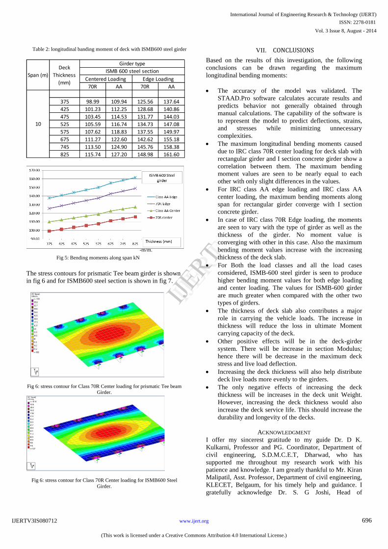
Table 2: longitudinal banding moment of deck with ISMB600 steel girder
70R AA 70R AA
375 98.99 109.94 125.56 137.64
425 101.23 112.25 128.68 140.86
475 103.45 114.53 131.77 144.03
525 105.59 116.74 134.73 147.08
575 107.62 118.83 137.55 149.97
675 111.27 122.60 142.62 155.18
745 113.50 124.90 145.76 158.38
825 115.74 127.20 148.98 161.60
10
Span (m)
Deck
Thickness
(mm)
Girder type
ISMB 600 steel section
Centered Loading Edge Loading
Fig 5: Bending moments along span kN
-m/m.
The stress contours for prismatic Tee beam girder is shown
in fig 6 and for ISMB600 steel section is shown in fig 7.
Fig 6: stress contour for Class 70R Center loading for prismatic Tee beam Girder.
Fig 6: stress contour for Class 70R Center loading for ISMB600 Steel
Girder.
VII. CONCLUSIONS
Based on the results of this investigation, the following
conclusions can be drawn regarding the maximum
longitudinal bending moments:
The accuracy of the model was validated. The
STAAD.Pro software calculates accurate results and
predicts behavior not generally obtained through
manual calculations. The capability of the software is
to represent the model to predict deflections, strains,
and stresses while minimizing unnecessary
complexities.
The maximum longitudinal bending moments caused
due to IRC class 70R center loading for deck slab with
rectangular girder and I section concrete girder show a
correlation between them. The maximum bending
moment values are seen to be nearly equal to each
other with only slight differences in the values.
For IRC class AA edge loading and IRC class AA
center loading, the maximum bending moments along
span for rectangular girder converge with I section
concrete girder.
In case of IRC class 70R Edge loading, the moments
are seen to vary with the type of girder as well as the
thickness of the girder. No moment value is
converging with other in this case. Also the maximum
bending moment values increase with the increasing
thickness of the deck slab.
For Both the load classes and all the load cases
considered, ISMB-600 steel girder is seen to produce
higher bending moment values for both edge loading
and center loading. The values for ISMB-600 girder
are much greater when compared with the other two
types of girders.
The thickness of deck slab also contributes a major
role in carrying the vehicle loads. The increase in
thickness will reduce the loss in ultimate Moment
carrying capacity of the deck.
Other positive effects will be in the deck-girder
system. There will be increase in section Modulus;
hence there will be decrease in the maximum deck
stress and live load deflection.
Increasing the deck thickness will also help distribute
deck live loads more evenly to the girders.
The only negative effects of increasing the deck
thickness will be increases in the deck unit Weight.
However, increasing the deck thickness would also
increase the deck service life. This should increase the
durability and longevity of the decks.
ACKNOWLEDGMENT
I offer my sincerest gratitude to my guide Dr. D K.
Kulkarni, Professor and PG. Coordinator, Department of
civil engineering, S.D.M.C.E.T, Dharwad, who has
supported me throughout my research work with his
patience and knowledge. I am greatly thankful to Mr. Kiran
Malipatil, Asst. Professor, Department of civil engineering,
KLECET, Belgaum, for his timely help and guidance. I
gratefully acknowledge Dr. S. G Joshi, Head of
International Journal of Engineering Research & Technology (IJERT)
Vol. 3 Issue 8, August - 2014
IJERT
IJERT
ISSN: 2278-0181
www.ijert.orgIJERTV3IS080712
(This work is licensed under a Creative Commons Attribution 4.0 International License.)
696
Department, Civil Engineering, S.D.M.C.E.T, for his
encouragement and suggestions. Also I would like to take
this opportunity to thank Dr. S. Mohan Kumar, Principal,
S.D.M.C.E.T, for his encouragement.
REFERENCES [1] L. Deng, C.S. Cai., “Identification of parameters of vehicles moving
on bridges”, Engineering Structures 31 (2009) 2474_2485.
[2] S.S. Law., J.Q. Bu., X.Q. Zhu., S.L. Chan., “Vehicle axle loads identification using finite element method”, Engineering Structures 26 ( 2004) 1143–1153.
[3] Adrian Kidarsa., Michael H. Scott., Christopher C. Higgins., “Analysis of moving loads using force-based finite elements”, Finite Elements in Analysis and Design 44 (2008) 214 – 224.
[4] L. Yu., Tommy H.T. Chan., “Recent research on identification of moving loads on bridges”, Journal of Sound and Vibration 305 (2007) 3–21.
[5] Kanchan Sen Gupta., Somnath Karmakar., “Investigations on simply supported concrete bridge deck slab for IRC vehicle loadings using finite element analysis”, International Journal of Earth Sciences and Engineering ISSN 0974-5904, Volume 04, No 06 SPL, October 2011, pp 716-719.
[6] Claude Broquet., Simon., Bailey., Mario Fafard., and Eugen Bruhwiler., “Dynamic behavior of deck slabs of concrete road”, Journal of Bridge Engineering, Vol. 9, No. 2, March 1, 2004. ©ASCE, ISSN 1084-0702/2004/2- 137–146.
[7] Daniel M. Balmer., and George E. Ramey., “Effects of bridge deck thickness on properties and behavior of bridge decks”, Practice Periodical on Structural Design and construction, Vol. 8, No. 2, May 1,2003. ©ASCE, ISSN 1084-0680/2003/2- 83–93.
[8] Lina Ding., Hong Hao., Xinqun Zhu., “Evaluation of dynamic vehicle axle loads on bridges with different surface conditions”, Journal of Sound and Vibration 323 (2009) 826–848.
International Journal of Engineering Research & Technology (IJERT)
Vol. 3 Issue 8, August - 2014
IJERT
IJERT
ISSN: 2278-0181
www.ijert.orgIJERTV3IS080712
(This work is licensed under a Creative Commons Attribution 4.0 International License.)
697


