Development of more robust bridge deck...
94
Development of more robust bridge deck slabs Potentials of Ultra High Performance Fiber Reinforce Concrete) Master of Science Thesis in the Master’s Programme Structural Engineering and Building Performance Design FAHEEM AHMAD KHAN FARIDOON SOHAIB NAZAR Department of Civil and Environmental Engineering Division of Structural Engineering Concrete Structures CHALMERS UNIVERSITY OF TECHNOLOGY Göteborg, Sweden 2011 Master’s Thesis 2011:72
Transcript of Development of more robust bridge deck...

Development of more robust bridge deck slabs Potentials of Ultra High Performance Fiber Reinforce Concrete) Master of Science Thesis in the Master’s Programme Structural Engineering and Building Performance Design
FAHEEM AHMAD KHAN FARIDOON SOHAIB NAZAR Department of Civil and Environmental Engineering Division of Structural Engineering Concrete Structures CHALMERS UNIVERSITY OF TECHNOLOGY Göteborg, Sweden 2011 Master’s Thesis 2011:72

MASTER’S THESIS 20112011:72
Development of more robust bridge deck slabs
Potentials of Ultra High Performance Fiber Reinforce Concrete)
Master of Science Thesis in the Master’s Programme Structural Engineering and Building Performance Design
FAHEEM AHMAD KHAN FARIDOON
SOHAIB NAZAR
Department of Civil and Environmental Engineering Division of Structural Engineering
Concrete Structures CHALMERS UNIVERSITY OF TECHNOLOGY
Göteborg, Sweden 2011

Development of more robust bridge deck slabs Potentials of Ultra High Performance Fiber Reinforce Concrete) Master of Science Thesis in the Master’s Programme Structural Engineering and Building Performance Design FAHEEM AHMAD KHAN FARIDOON SOHAIB NAZAR
© FAHEEM AHMAD KHAN FARIDOON & SOHAIB NAZAR, 2011
Examensarbete / Institutionen för bygg- och miljöteknik, Chalmers tekniska högskola 2011:72 Department of Civil and Environmental Engineering Division of Structural Engineering Concrete Structures Chalmers University of Technology SE-412 96 Göteborg Sweden Telephone: + 46 (0)31-772 1000 Cover: Proposed cross section of the composite bridge deck with NSC prefabricated Slab and UHPFRC Overlay, section 8.2.1, page 70 of the report Chalmers reproservice Göteborg, Sweden 2011


I
Development of more robust bridge deck slabs Potentials of Ultra High Performance Fiber Reinforce Concrete) Master of Science Thesis in the Master’s Programme Structural Engineering and Building Performance Design FAHEEM AHMAD KHAN FARIDOON SOHAIB NAZAR Department of Civil and Environmental Engineering Division of Structural Engineering Concrete Structures Chalmers University of Technology
ABSTRACT
Parts of the bridges in Sweden and other countries have shown to have a too low resistance with respect to deterioration. This leads to costly repair interventions that disturbs the traffic and results in high Life Cycle Costs (LCC) for the bridges. This is the case for the bridge deck slabs with connecting elements, such as edge beams, railings, expansion joints, sealing and pavement. The aim of this master thesis is to investigate the problems in bridge deck slabs, suggest possible solutions to these problems and in particular, find the potentials of Ultra High Performance Fiber Reinforced (UHPFRC) Concrete for these problems.
Bridge deck slabs and their connecting elements deteriorate faster than the other parts of the bridge due to traffic loads and use of de-icing salts during winter. The various mechanisms of the deterioration that take place in bridge deck slabs are corrosion of reinforcement, cracking, spalling, delamination and potholes. A state-of-the-art description has been presented including suggestions to possible solutions to these problems, such as cathodic protection and galvanizing of the steel reinforcement, use of corrosion inhibitors, use of fiber reinforced concrete and polymers, and bridges with integral abutments.
This investigation primarily focuses on the mechanical behaviour, durability and rheological properties and application of UHPFRC to develop more robust bridge deck slabs. UHPFRC shows better performance at post-cracking due to the strain hardening behaviour with distributed micro-cracks, enhancing the service life of bridge deck slabs.
An inventory of two bridges in Sweden has been used as case studies to investigate and illustrate the possibility to use UHPFRC in their construction and rehabilitation. UHPFRC is an almost impermeable and highly ductile material; however, being relatively expensive, it has been only suggested to be used as overlay, for bridge deck slab and edge beams for rehabilitation as well as new construction. It has also been suggested that UHPFRC should be used in joints for connecting precast elements, giving a continuous bridge deck with narrower (smaller/ thinner) and stronger joints.
Key words: Bridge deck slabs, UHPFRC, Robust, Life Cycle Cost, Interventions, Strain hardening

II

CHALMERS Civil and Environmental Engineering, Master’s Thesis 2011:72 III
Contents
1 INTRODUCTION 1
1.1 Background 1
1.2 Purpose 1
1.3 Aims and objectives 2
1.4 Method and Scope 2
2 DESIGN OF BRIDGE DECK SLABS 4
2.1 General 4
2.2 Reinforced concrete bridge deck slabs 6 2.2.1 Solid slabs 6 2.2.2 Voided slab 6 2.2.3 Ribbed slab 7
2.3 Edge beams 7
2.4 Expansion joints 7
2.5 Railings 8
2.6 Carriageway drainage 8
2.7 Sealing 9
2.8 Pavements 9
3 WEAKNESSES IN CONCRETE BRIDGE DECKS 11
3.1 Deterioration of bridge deck slabs 11 3.1.1 Cracking 11 3.1.2 Abrasion 15 3.1.3 Delamination 16 3.1.4 Potholes 16
3.2 Damages to edge beam 16
3.3 Damages to expansion joints 17
3.4 Damages to railings and parapets 18
3.5 Damages to drainage system 18
3.6 Damages to sealing 19
3.7 Damages to pavement/overlay 19
4 POSSIBLE SOLUTIONS 20
4.1 Cathodic protection of steel reinforcement 20
4.2 Protective coating of reinforcement bars 21
4.3 Use of corrosion inhibitors 21

CHALMERS, Civil and Environmental Engineering, Master’s Thesis 2011:72 IV
4.4 Fiber Reinforced Polymers (FRP) composites 21
4.5 Fiber Reinforced Concrete (FRC) 22
4.6 Integral abutment bridges as a possible solutions for damages with expansion joints 24
4.6.1 New York State Department of Transportation's experience 25 4.6.2 United Kingdom experience 25 4.6.3 Swedish practices of integral abutment bridges 25 4.6.4 German design of integral abutment bridges 26
5 ULTRA HIGH PERFORMANCE FIBER REINFORCED CONCRETE (UHPFRC) 27
5.1 Historical overview 28
5.2 Composition 29 5.2.1 Cement 30 5.2.2 Sand 31 5.2.3 Silica fume 31 5.2.4 Superplasticizer 31 5.2.5 Fibers 31
5.3 Types of UHPFRC 32
5.4 Properties of fresh UHPFRC 34 5.4.1 Workability 34 5.4.2 Hydration and heat generation 35 5.4.3 Self dessication 36
5.5 Material properties for the hardened UHPFRC 37 5.5.1 Permeability 37 5.5.2 Mechanical response in tension 38 5.5.3 Mechanical response in compression 39 5.5.4 Effect of fibers on mechanical properties 40 5.5.5 Thermal expansion 40 5.5.6 Shrinkage 41 5.5.7 Creep 43 5.5.8 Fatigue behavior 44
5.6 Durability properties 45 5.6.1 Chloride penetration 46 5.6.2 Freeze –Thaw resistance 46 5.6.3 Alkali Silica Reaction 46 5.6.4 Abrasion resistance 47
6 APPLICATION OF UHPFRC TO BRIDGE DECKS 49
6.1 Rehabilitation with UHPFRC 49 6.1.1 SAMARIS (Sustainable and Advanced Materials for Road Infrastructures) European Project 50 6.1.2 Barrier (Parapet) wall of bridge 51 6.1.3 LOG ČEZOŠKI Bridge Slovenia 52 6.1.4 Pinel Bridge, France 52

CHALMERS Civil and Environmental Engineering, Master’s Thesis 2011:72 V
6.2 New bridges constructed with UHPFRC 53 6.2.1 Experimental validation of a ribbed UHPFRC bridge deck in France 53 6.2.2 Use of BCV® for bridge construction in France 53 6.2.3 Use of RESCON for bridge construction in Austria 53 6.2.4 Use of Ductal® for bridge construction in Canada 54 6.2.5 US Highway Bridges 54 6.2.6 Shepherds Creek Road Bridge, NSW, Australia 57 6.2.7 Papatoetoe Footbridge, New Zealand 57 6.2.8 Sakata-Mirai Foot bridge, Japan 57
6.3 Life cycle cost analysis of UHPFRC bridge 58
7 CASE STUDY- THE KÄLLÖSUND BRIDGE 60
7.1 Description of the bridge 60
7.2 Damage detection and replacement of the edge beams 61
7.3 Rehabilitation alternative with UHPFRC 62 7.3.1 Composition of UHPFRC 63 7.3.2 Application of UHPFRC 64 7.3.1 Environmental impact 65
7.4 Comparison of the two alternatives 66
8 CASE STUDY: BRIDGE OVER TOLÅNGAÅN 67
8.1 Description of the bridge 67
8.2 Bridge alternative with prefabricated bridge deck slabs and UHPFRC 69 8.2.1 Description of the bridge 69 8.2.2 Joints Details 70 8.2.3 Application of UHPFRC overlay 71 8.2.4 Comparison of bridge deck alternatives 72
9 CONCLUSIONS 73
10 FURTHER STUDIES 75
11 REFERENCES 76

CHALMERS, Civil and Environmental Engineering, Master’s Thesis 2011:72 VI
CHALMERS Civil and Environmental Engineering, Master’s Thesis 2011:72 VII
Preface
This master thesis was carried out at Chalmers University of Technology, at the department of Civil and Environmental Engineering, Division of Structural Engineering, Concrete Structures, in Göteborg, Sweden. The work is a part of a larger cooperation project between the Swedish technical universities (Chalmers, KTH, LTU and LTH) and the Swedish Transport Administration.
At first, we are most grateful to our supervisor and examiner Assistant Professor Mario Plos for his guidance, support, encouragement and valuable feedback. We could not have done this without his help and appreciation. He read our report and discussed it with us with great interest. It was our great pleasure to work under his guidance.
We are also very thankful to our friends who have always supported us. Furthermore, a special gratitude to our present and former teachers, for helping us to reach to this stage.
Finally, thanks to our Parents, who bestowed their love upon us, took care of us, helped and guided us, and supported us in every single moment of our life.
Göteborg June 2011
Faheem Ahmed Khan Faridoon
Sohaib Nazar Awan

CHALMERS, Civil and Environmental Engineering, Master’s Thesis 2011:72 VIII
Notations
Roman lower case letters
fcd Design value of concrete compressive strength fck Characteristic compressive cylinder strength of concrete at 28 days Ecm Mean elastic modulus of Concrete fctm Mean tensile strength of concrete Gf Fracture Energy of Concrete kw Water Permeability fyk Tensile Strength of Steel reinforcement
Greek lower case letters
Є Strain
v Poisson ratio α Co‐efficient of thermal expansion σ Stress σ-ω Stress-crack opening αcc Coefficient for long term effects on compressive strength γC partial safety factor for concrete
Abbreviations
UHPFRC Ultra High Performance fiber Reinforced Concrete FRC Fiber Reinforced Concrete HPC High Performance Concrete NSC Normal strength Concrete LCC Life Cycle Cost CRC Compact Reinforced Composite ARCHES Assessment and Rehabilitation of Central European Highway
structures SAMARAIS Sustainable and Advanced Materials for Road Infrastructure FRP Fiber Reinforced Polymer FE Finite Element NYSDOT New York State Department of Transportation CP Cathodic Protection BCV Beton Composite Vicat RPC Reactive Powder Concrete ASR Alkali Silica Reaction EPFL Ecole Polytechnique Federale de Lausanne LCPC Laboratoire Central Des Ponts Et Chaussees CTE Co-efficient of Thermal Expansion ASTM American Standard for Testing Materials AASHTO American Association for State Highways and Transport
Officials AFGC Association Francaise de Genie Civil SETRA Service D'etudes Techniques des Routes et Autoroutes

CHALMERS, Civil and Environmental Engineering, Master’s Thesis 2011:72 1
1 Introduction
Roads are the major prerequisite for transportation and connection for mankind. For smooth flow of transport, a highway is intended to adopt the shortest possible route with comfortable and acceptable profile. The highway needs to pass valleys, mountains, deserts and rivers. Many factors intersect the intentional profile of the highway, where water, other roads and railways are the most frequent ones. Therefore, bridges are constructed along the route of the highway for crossing of these hinders with the intention to connect the different parts of the highway. Hence, bridges are a key factor to make the aim of the highways achievable.
Bridges are designed by qualified and experienced bridge engineers, keeping in view safety, economy, aesthetics and environmental considerations together with production and maintenance aspects. There are different conceptual and detailed design methods available following different design codes. Each design code has the intension to support the design to achieve the vital goals of the bridge. Quality assurance is the first priority during the design and construction process in order to guaranty a good life time performance of the bridge. However, with the passage of time deterioration and degradation occurs in the bridge, which eventually requires maintenance, repair and rehabilitation. Investigation has been done to improve the design methods to ensure safety throughout the life time of the structure and reduce the maintenance cost.
1.1 Background
Parts of the bridges in Sweden and other countries have shown to have a too low resistance with respect to deterioration. This leads to costly repair interventions that disturbs the traffic and results in high life cycle costs (LCC) for the bridges. The parts that have shown a too low resistance are typically those that are particularly exposed to traffic, weather and environmental impact. This is the case for the bridge deck slabs with connecting elements, such as edge beams, railings, expansion joints, sealing and pavement.
The Swedish Transport Administration has the ambition to improve the performance of the bridge deck slabs to reduce the resources spent on maintenance and repair and to reduce the carbon dioxide emissions. A joint pre-study is currently being performed by the Swedish technical universities (Chalmers, KTH, LTU and LTH) and CBI (Swedish cement and concrete research institute) for the Swedish Transport Administration to identify weaknesses and development potentials of concrete bridge deck slabs with connecting elements, and to suggest further research. The master thesis is intended to support and complement this pre-study.
1.2 Purpose
The purpose of this master’s thesis was to perform a literature study and a state-of-the-art description of concrete bridge deck slabs with connecting elements. The focus

CHALMERS, Civil and Environmental Engineering, Master’s Thesis 2011:72 2
was on parts and functions that show a too low resistance and on possible solutions to the identified problems. Furthermore, the aim was to make an in-depth study of one of the possible solutions to the identified problems.
1.3 Aims and objectives
The overall aim of the work was to contribute to the improvement of the life cycle performance of bridge deck slabs in order to reduce the resources spent on repair and maintenance and to reduce the carbon dioxide emissions associated with this.
The objectives of this study were therefore:
To identify weaknesses and development potentials of concrete bridge deck slabs, including connecting elements such as edge beams, railings, expansion joints, sealing, pavement and drainage systems.
To study the potential of existing interventions and give suggestions for further development.
To do in-depth study on the possibility to improve the strength and structural stability by using ultra high performance fiber reinforced concrete (UHPFRC).
To suggest an economical way to apply UHPFRC for rehabilitation and for construction of more robust bridge deck slabs.
1.4 Method and Scope
The study was mainly performed as a literature study. Based on the literature study, alternative design solutions for more robust deck slabs were proposed for two existing bridges, and compared to original design solutions.
The literature study was initially focussed on the current design methods and design practise of bridge decks. Then these design methods and design practise were critically reviewed to gather information about the weaknesses in the bridge deck slab and connecting elements. Thereafter investigations were done to find possible solutions to overcome these weaknesses and to judge the potentials of the suggested solutions. Applications of different methods to improve the resistance of bridge deck slabs against deterioration were studied.
One of the most promising solutions was to use Ultra High Performance Fiber Reinforced Concrete (UHPFRC). An in-depth study was done on the properties of UHPFRC in the development of more robust bridge deck slabs. Furthermore, previous experiences of application of UHPFRC for bridges in the world were studied.
Finally, two case studies were performed. In the first case study, the use of UHPFRC for rehabilitation of existing bridges was theoretically applied on a bridge deck slab. An existing bridge with insufficient durability for the deck slab and deteriorated edge beams was chosen as a reference bridge. In second case study, a comparison was done between an industrially produced bridge alternative and a reference composite bridge,

CHALMERS, Civil and Environmental Engineering, Master’s Thesis 2011:72 3
conventionally produced with a cast in-situ normal strength concrete bridge deck slab. The new alternative bridge solution considered of main steel girders and prefabricated normal strength bridge deck elements joined and covered with UHPFRC.

CHALMERS, Civil and Environmental Engineering, Master’s Thesis 2011:72 4
2 Design of Bridge Deck Slabs
2.1 General
The design procedures used today were originally created by research and development, and proved to be adequate and applicable by experience. Initially, a preliminary survey of the construction site and highway is carried out for the conceptual design of a bridge. During this stage, data is collected about the profile and alignment of the highway, topography of the area, soil properties, current of the flow of water, wind, snow and ice formation and projected traffic volume. This leads to the decision of the shape and type of bridge, length and number of spans, type of abutments and foundation, and load on the structure.
Figure 2.1 Svinesund Bridge between Sweden and Norway. Adopted form (trafikverket, 2007).
Thereafter, the bridge designer develops the detailed structural design such as drawings and dimensions of the structure considering connection details, drainage from the bridge, lightning, sealing and surface coating, water proofing, sidewalks and railings.
The structural system of a bridge can often be described in terms of the longitudinal and transverse load carrying structures. The longitudinal structural system of a bridge may be designed for, for example, beam, frame, arch, cable stayed, or suspension action. The transverse structural system normally consists of a bridge deck slab with connecting elements such as edge beams, railings, parapets, drainage system, sealing, asphalt layer and expansion joints. For longer bridges it transfers the traffic loads to the main (longitudinal) load carrying system. For short bridges the deck transfers the loads to the supports directly (Ryall et al. 2000).

CHALMERS, Civil and Environmental Engineering, Master’s Thesis 2011:72 5
For larger spans, from approximately 25 m, prestressed concrete bridges have shown great result. Since concrete is strong in compression but weak in tension, pre-stressing leads to better performance in serviceability limit state with no or less cracking and smaller deflection. In ultimate limit state, more or higher quality reinforcement may result in higher capacity but the prestressing itself has only a minor influence on the capacity. Prestressing gives a very free choice to the bridge engineer while deciding the shape and length of bridge. Prestressing is an advanced system of construction of concrete bridges with good serviceability performance. The designer decides about the dimensions of the structure and reinforcement according to the ultimate limit state analysis in flexure, torsion, shear and punching shear, and for crack widths in the serviceability limit states (Ryall et al. 2000).
Steel was earlier the favourite material for long span bridges because of its high strength. However, the technique of prestressing has to a great extent replaced the steel as bridge material. A main reason is that concrete requires less maintenance cost particularly with respect to corrosion compared to pure steel bridges. However, steel is commonly used for the main girders in medium and long span composite bridges with concrete decks and substructures. The combination of prefabricated prestressed girders with cast-in-situ deck is a widely used construction method for bridges in many parts of the world (Raju, 2007).
The deck is a vital part of the bridge and functions as a pathway for all types of traffic. It is directly exposed to all environmental conditions occurring in the area of location of the bridge throughout the year. Therefore, it should be strong and durable enough to withstand chemical and mechanical effects of rain water, de-icing salt, friction between the tires and deck surface, and the traffic load. The deck consists typically of a slab, edge beams, sealing, road pavement, expansion joints, drainage system, railings and lightning as shown in the Figure 2.2.
Figure 2.2 Typical section of a bridge superstructure.

CHALMERS, Civil and Environmental Engineering, Master’s Thesis 2011:72 6
2.2 Reinforced concrete bridge deck slabs
Reinforced concrete is the most widely used construction material for bridges. Cast-in-situ reinforced concrete bridges are simple to construct. It gives good results when the span of the bridge is less than 25 m. However, for the bridges having longer span, the dead weight becomes larger (Ryall et al. 2000).
There are different materials used for the construction of the bridge deck slabs, of which concrete and steel are the most prominent and widely used throughout the world. However, steel has proved to be an expensive material to use for bridge deck slab construction and concrete is the dominant material. Other types of construction materials for bridge deck slabs are stress-laminated timber and Fiber Reinforced Polymer (FRP). The main advantage of using these materials for the construction of bridge deck is that they together with orthotropic-steel decks form very light weight bridge decks. Consequently, especially orthotropic steel is used for the construction of longer bridges to control the weight problem. The bridge deck is most commonly constructed of reinforced concrete because of the in-situ workability and the good ability to distribute the loads. Reinforced concrete is most cost-effective for slab structures because it distributes the concentrated loads in two directions (Domone & Illston, 2010).
A concrete bridge deck slab is designed for serviceability limit state and ultimate limit state. The design differs depending on the specific geometrical, environmental and traffic conditions. In the world, there are two codes widely used for the design of bridge deck slabs today: AASHTO-LRFD, (AASHTO, 2010) and Eurocode 2-Part 2, (CEN, 2004). For the bridge decks different type of cross sections are used depending on the acting load, span of the bridge, construction material and aesthetics. The most common type of deck slabs used in Sweden is solid slabs but ribbed and voided slabs do also occur.
2.2.1 Solid slabs
This is the simplest type of bridge deck slab used for short span bridges. Solid slab bridges are efficient in distributing the concentrated loads. These are one way or two way spanning. Mostly solid slab bridge is simply supported. The solid slab can be constructed monolithic or non-monolithic with the abutment (Ryall et al. 2000).
2.2.2 Voided slab
Above a span of about 10m, the dead weight of a solid slab bridge becomes excessive. Hence, the use of voids inside the deck slab gives a positive result by reducing the weight of the slab. The provided void diameter is not more than 60% of the slab thickness. Polystyrene void formers are used in circular shapes. Transverse reinforcement is provided in the flanges. Flexural and shear design is done longitudinally as well as transversely for the section. Mostly these are precast structures requires minimum formwork thus accelerating the speed of construction (Ryall et al. 2000).
CHALMERS, Civil and Environmental Engineering, Master’s Thesis 2011:72 7
However, the trend of voided slab is not yet adopted in Sweden due to problems with the quality in production of these slabs. Furthermore, it is difficult to inspect these voids for regular maintenance activities.
2.2.3 Ribbed slab
Here, the slab has several longitudinal ribs or beams, cast together with the slab. Transverse beams are provided over the supports. The load distribution is relatively poor, hence, transverse beams can be provided at the middle of span to avoid sagging (Ryall et al. 2000).
2.3 Edge beams
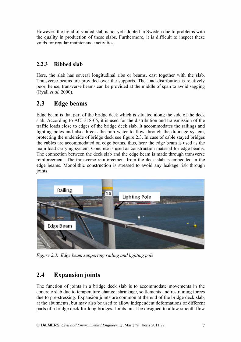
Edge beam is that part of the bridge deck which is situated along the side of the deck slab. According to ACI 318-05, it is used for the distribution and transmission of the traffic loads close to edges of the bridge deck slab. It accommodates the railings and lighting poles and also directs the rain water to flow through the drainage system, protecting the underside of bridge deck see figure 2.3. In case of cable stayed bridges the cables are accommodated on edge beams, thus, here the edge beam is used as the main load carrying system. Concrete is used as construction material for edge beams. The connection between the deck slab and the edge beam is made through transverse reinforcement. The transverse reinforcement from the deck slab is embedded in the edge beams. Monolithic construction is stressed to avoid any leakage risk through joints.
Figure 2.3. Edge beam supporting railing and lighting pole
2.4 Expansion joints
The function of joints in a bridge deck slab is to accommodate movements in the concrete slab due to temperature change, shrinkage, settlements and restraining forces due to pre-stressing. Expansion joints are common at the end of the bridge deck slab, at the abutments, but may also be used to allow independent deformations of different parts of a bridge deck for long bridges. Joints must be designed to allow smooth flow

CHALMERS, Civil and Environmental Engineering, Master’s Thesis 2011:72 8
of traffic, safety for pedestrians and bikers, lowest possible noise from the traffic flow and to have enough strength to support the traffic load. They should resist leakage of de-icing salt water and other environmental affects. There are different kind of materials used for these joints such as asphalt, rubber, plastic, steel, epoxy and some other chemical materials. Joints are designed in numerous shapes and sizes depending upon the function for allowable movement impact (Chen et al. 2000).
Expansion joints are designed for serviceable limit state as well as ultimate limit state to ensure durability throughout the lifetime of bridge. There are three basic types of joints designed according to the accommodated movement. Small movement joints accommodate motion up to 45 mm, medium from 45 mm to 130 mm and large from 130 mm onwards (Chen et al. 2000).
The bridge deck slab can be constructed monolithic or non-monolithic with the abutment Non-monolithic section shows a lower resistance to deterioration due to leakage of drainage water and wear and tear in the expansion joints which affects the pier and sub-structure abruptly. Maintenance and repair cost is much higher as it is cumbersome to work on the sub-structure (Ryall et al. 2000).
Therefore, monolithic structures are commonly preferred for short and normal span bridges to avoid the problem of deterioration of sub-structure. Furthermore, integration of the bridge deck slab with the abutments reduces the sagging moments in the mid-span of the slab (Ryall et al. 2000).
2.5 Railings
Railings are protections provided at the edges of the bridge deck slab to save the vehicle, in case of collision or accident, from falling down from the bridge. Railings are also provided to separate the bicycle and pedestrians pathways from the main vehicular lanes. Therefore, railings should be strong enough to accommodate the impact from a vehicle at the time of an accident. At the same time, the railings should be deformable and should absorb energy in order to minimize the impact on drivers and passengers in case of an accident. Generally, steel, wood, plastic and reinforced concrete are used as material of construction for railings. The choice of material and type of railings depend upon the traffic volume and type of traffic. AASHTO recommends crash test to determine the type of railings to be used (Chen et al. 2000). Also In Europe and Sweden, Crash tests are performed to determine the quality of railings to be used. Steel is the most dominant material used for railings in Sweden due to its strength, deformability and good performance in case of accidents.
2.6 Carriageway drainage
Water and substances suspended in water is the major enemy of the concrete structures. Water can appear in the form of snow, rain and ice during the life time of a bridge. In particular, the de-icing salts, when mixed with water, can seriously affect the concrete bridge deck slab. Penetration of saline water into concrete structures can cause corrosion of steel bars and freeze-thaw deterioration. The carriageway drainage

CHALMERS, Civil and Environmental Engineering, Master’s Thesis 2011:72 9
system reduces the possibility of standing water on the bridge deck surface and allows a smooth flow of water away from the bridge. The water from the drainage system should not affect the sub structure and foundation. While designing and constructing the bridge deck slab, attention should be given to the drainage system. Different types of drainage elements are installed in the deck of the bridge depending on the function and necessity (Ryall et al. 2000). In Sweden, there are two types of drainage systems in bridge decks. One is external drainage system and the other is internal drainage system. The rain water drops directly on the asphalt layer on the bridge deck. The deck slab is sloped towards the edges to direct the water towards the edge beam. Pipes are installed at different locations between the deck slab and edge beams for carrying this rain water from the deck to the reservoir. However, some amount of water penetrates from the asphalt layer inside the deck slab. To drain this water, pipes of small sizes are installed at different locations to drain off this water to the reservoir.
.
2.7 Sealing
Sealers are used on concrete bridge deck slabs to increase the durability and service life of the structure, thus reducing the life cycle cost. Sealers are used as moisture protection on concrete bridge deck slabs by preventing the slab from contact with polluted water. In this way, corrosion of steel bars can be avoided to a considerable level (Ryall et al. 2000).
A variety of sealers are used depending on the density of concrete and type of environment. Most of them are organic in nature such as penetrating sealers, polymer coatings and bituminous sealers (Ryall et al. 2000).
Penetrating sealers are products which are absorbed on the surface of concrete forming a water repelling surface. It allows water vapours to pass because there are pores and cracks in concrete which help in the drying process (Ryall et al. 2000).
Polymer coatings are products which forms a film or a membrane on the surface of concrete structure, and which does not allow water to penetrate into the concrete structure. It does not allow water vapour to pass (Ryall et al. 2000).
Bituminous sealers are products which are used as a water repelling membrane between the concrete bridge deck slab and the asphalt surface (Ryall et al. 2000).
2.8 Pavements
The layer of asphalt is spread on the top of the sealing in order to protect the concrete slab from mechanical abrasion and to provide a smooth surface for the traffic. The asphalt layer is usually bituminous concrete which consists of bitumen mixed with sand and coarse aggregates. This is also called wearing course. This layer forms the top surface of the bridge deck slab. Sometimes liquid bitumen is also spread on the top of this wearing layer. The pavement is designed to obtain the required friction between the tires and the wearing course. Typical Swedish bridge deck slabs with sealing and pavement have been shown in the Figure 2.4 (a) and Figure 2.4 (b).

CHALMERS, Civil and Environmental Engineering, Master’s Thesis 2011:72 10
Figure 2.4 (a) Example of composition of a Bridge deck slab with sealing and pavement.
Figure 2.4 (b) Example of composition of a bridge deck slab with protective concrete and pavement (Adapted from Paulsson 1999).

CHALMERS, Civil and Environmental Engineering, Master’s Thesis 2011:72 11
3 Weaknesses in Concrete Bridge Decks
Bridge decks are constantly subjected to concentrated traffic loads and are exposed to environment actions. Consequently, they deteriorate faster than other parts of the bridge. Also during winter, de-icing salts are used to keep the roads free from ice and they are spread over the bridge decks. De-icing salts, which are generally a mixture of sodium chloride and calcium chloride penetrate into the concrete and cause deterioration of the concrete structure and in particular, the steel reinforcement (Frangopol et al, 2003).
Deck accessories exhibit various types of damages and these damages can be of different importance e.g. damages to the connection between edge beam and slab, expansion joints, water proving membranes, pavement and elements of drainage system are most dangerous (Radomski, 2002).
3.1 Deterioration of bridge deck slabs
The deterioration in the bridge deck slab is mainly due to poor material quality (poor mix, curing conditions), poor weather conditions (freeze and thaw cycles), use of de-icing salts and increasing traffic loads. The various mechanisms of the deterioration that take place in bridge deck slab are cracking and spalling, abrasion, delamination and potholes (Frangopol et al, 2003).
3.1.1 Cracking
Concrete cracks in fresh as well as in hardened state. Cracks makes it easier for chlorides to penetrate into the concrete and cause corrosion of steel reinforcement The most common causes of cracking in bridge deck slabs are shrinkage stresses, temperature changes, corrosion of steel reinforcement, chemical reactions in the concrete (alkali-aggregate reaction) and mechanical loading causing flexure and shear cracks (Radomski, 2002).
Cracking that occur before hardening are mostly caused by plastic shrinkage and plastic settlement of the concrete mix. Due to extreme weather conditions the evaporation rate of water may increase while the concrete is still in a plastic state, causing surface to shrink more than the interior concrete and resulting in surface cracks (Yazdani & Kleinhans, 2008). Furthermore, poor mix design can cause excessive bleeding of the mix leading to plastic settlement. Also movement of formwork in the fresh state of the concrete can induce cracking (Sustainable bridges, 2007).
Extreme weather conditions at the time of casting and heat produced during hydration induces thermal stresses in concrete. Restraint to these thermal stresses can cause cracking of concrete. Bridge decks may exhibit a high degree of restrain due to composite action of the deck and supporting girders if they are not cast at the same time. Due to the hydration reaction during casting the temperature of the concrete

CHALMERS, Civil and Environmental Engineering, Master’s Thesis 2011:72 12
deck slab increases. If the temperature of the girder remains unchanged, thermal stresses are developed in longitudinal direction. To relieve these stresses the deck will crack in transverse direction, perpendicular to the stress direction. Thermal stresses also develop in the concrete due to temperature gradient through the thickness of deck, regardless of restraint. This difference in gradient may produce non uniform strain (Brown et al. 2001). Furthermore, restraint to shrinkage stresses also cause cracking in the deck. This is a problem when edge beams or parts of a bridge deck are replaced for existing bridges. Furthermore, the restraint caused by the steel girders when casting the concrete deck may cause shrinkage cracks for composite bridges.
Poor structural detailing may also cause cracking. Simply supported spans allow free rotation at supports, therefore thermal and shrinkage stresses are uniform along the length of the span. However, continuous spans provide rotation restraints at the inner supports which may cause cracking over the interior supports if the provisions for restraints are not provided in the design. The transverse cracking is influenced by the thickness of deck, reinforcement spacing and concrete strength (Brown et al. 2001). Due to dead loads, flexure cracks may appear in fresh concrete in areas of negative moment. However, live loads also induce flexure cracks during service life (Yazdani & Kleinhans, 2008).
Furthermore, chemical reactions in the concrete e.g. Alkali-silica reaction, frost damage and corrosion of steel reinforcement also induce cracks in hardened concrete (Domone & IIIston, 2010).
Figure 3.1. Cracks in bridge deck slab
Alkali Silica Reaction
The problem occurs when high alkaline cement is used with reactive aggregate. Alkalies can also be contributed from admixtures and de-icing salts. In the presence of moisture, internal reaction takes place, causing disintegration of the concrete matrix.
When Alkalies in cement reacts with silica, a gel is formed which destroys the bond between the alkalies and cement paste. It is soft but absorbs large quantities of water and expands which results in cracking of concrete. This reaction is called as Alkali-Silica Reaction (ASR). Due to continued supply of water the cracks become larger

CHALMERS, Civil and Environmental Engineering, Master’s Thesis 2011:72 13
and extend in width. When expansion of cracks reaches to the surface either pop-outs form or map cracking occurs on the concrete surface as shown in Figure 3.2 (Domone & IIIston, 2010).
Figure 3.2 Cracking pattern due to Alkali- Silica reaction. Adapted from Domone & IIIston (2010)
Frost damage
Frost damage is a major cause of damage of concrete structures in cold areas. When free water inside the concrete pores freezes in winter, it expands. If there is no free space to accommodate this expansion the internal pressure leads to cracking of the concrete. Successive cycles of freezing and thawing lead to progressive cracking which leads to two types of damages. The first type is the internal freezing of the moisture inside the concrete which cause cracking and reduction of the strength and stiffness of the concrete. The second is the freezing of salt water in contact with the concrete surface, leading to surface scaling of the concrete. It also causes spalling of the damaged part of the concrete. The magnitude of internal pressure depends on the degree of saturation and the porosity of the concrete. One recommendation to prevent frost damage is the use of high strength concrete. Another common way to avoid frost damage is to increase the air content in the concrete mix (Domone & IIIston, 2010) (Hanjari, 2010).
Corrosion
A survey among European railway authorities showed that the major maintenance problem for concrete bridges are corrosion of reinforcement leading to spalling of concrete (Sustainable bridges, 2007). Since road bridges are even more exposed to de-icing salts, it can be expected that the problem is more severe here.
Corrosion is the disintegration of steel reinforcement due to its electrochemical reaction with the surrounding. Corrosion of reinforcement causes two major types of damages in bridge deck slabs. Firstly, the section of the reinforcement decreases which leads to reduction in capacity. Secondly, the corrosion products, the rust,

CHALMERS, Civil and Environmental Engineering, Master’s Thesis 2011:72 14
occupy a larger volume than the steel it originates from. As a result splitting forces are induced in the concrete which affects the concrete section in two ways; it destroys the bond between concrete and reinforcement and it will eventually cause spalling of the concrete cover reducing the capacity of section (Sustainable bridges, 2007).
There are three different types of corrosion of reinforcement in concrete bridges. The first type is uniform corrosion in which the reinforcement is equally corroded along and around its surface. It reduces the strength of the bond and eventually causes spalling of concrete (Sustainable bridges, 2007).
In second type, the reinforcement corrodes locally at some points on its surface. A high concentration of chlorides leads to pitting corrosion. This corrosion may lead to reduction of the corroded section of the reinforcement. The third type of corrosion occurs due to a combination of aggressive environmental actions and high stress concentrations, causing rupture failure of the reinforcement. In non-prestressed concrete bridges pitting or uniform corrosion is most common, while stress-corrosion mostly occurs in prestressed concrete bridges (Sustainable bridges, 2007).
Carbonation and chloride ingress are the major causes of corrosion of steel in concrete. Carbonation through the concrete cover causes mainly uniform corrosion of the reinforcement. It is due to reaction between carbon dioxide from the atmosphere and alkaline hydroxide in concrete. Alkalies in concrete pores form a passive layer of protective oxide on the steel surface which stops corrosion. During carbonation all the locally available calcium hydroxide will react and precipitate calcium carbonate, which results in lowering of pH, depassivation of the protective layer and finally the corrosion of steel will start. Corrosion due to carbonation mostly occurs in structures with low concrete cover and in concrete that has high permeability (Broomfield, 1997) (Sustainable bridges, 2007).
Chlorides ingress from the concrete cover mainly leads to pitting corrosion of the reinforcement. The area of reinforcement decreases at the pits. The chlorine itself is not used in the chemical reaction but it acts as a catalyst and helps in destroying the passive protective layer. Corrosion due to chloride ingress is usually a problem in coastal areas or in colder regions where high amount of de-icing salts are used in winter (Broomfield, 1997) (Sustainable bridges, 2007).
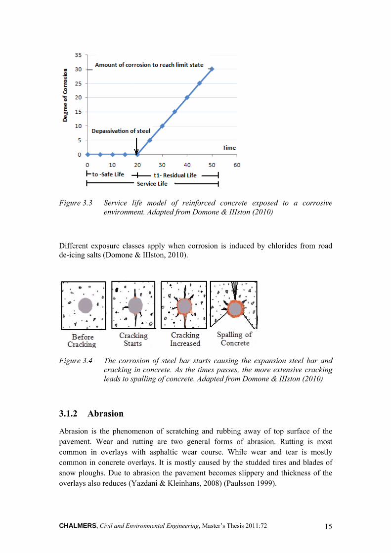
The total time to concrete cracking due to corrosion consist of two stages. In the first stage carbon dioxide and chlorides will take time to reach the steel; this can be considered as safe service life. The residual service life, in which corrosion takes place, continues until the limit state is reached and cracking and spalling of concrete way appear during this stage; see Figure 3.3 (Domone & IIIston, 2010).
CHALMERS, Civil and Environmental Engineering, Master’s Thesis 2011:72 15
Figure 3.3 Service life model of reinforced concrete exposed to a corrosive environment. Adapted from Domone & IIIston (2010)
Different exposure classes apply when corrosion is induced by chlorides from road de-icing salts (Domone & IIIston, 2010).
Figure 3.4 The corrosion of steel bar starts causing the expansion steel bar and cracking in concrete. As the times passes, the more extensive cracking leads to spalling of concrete. Adapted from Domone & IIIston (2010)
3.1.2 Abrasion
Abrasion is the phenomenon of scratching and rubbing away of top surface of the pavement. Wear and rutting are two general forms of abrasion. Rutting is most common in overlays with asphaltic wear course. While wear and tear is mostly common in concrete overlays. It is mostly caused by the studded tires and blades of snow ploughs. Due to abrasion the pavement becomes slippery and thickness of the overlays also reduces (Yazdani & Kleinhans, 2008) (Paulsson 1999).

CHALMERS, Civil and Environmental Engineering, Master’s Thesis 2011:72 16
3.1.3 Delamination
Due to low bond between old and new materials, separation along the contact plane occurs, called delamination. In decks with overlays, delamination is one of the most common types of deterioration. Delamination is a major problem in particular between the concrete and sealing of the membrane (Frangopol et al. 2003).
3.1.4 Potholes
Due to cracks in the overlays of deck, water seeps inside these cracks. When the water freezes during winter it expands and pushes the part of the overlay closest to the road surface away which leads to formation of potholes on the surface. The potholes can be irregular in shape, have different depth and have sharp edges. Potholes are usually formed in heavy traffic lanes (Frangopol et al. 2003).
Figure 3.5 Pothole formed on the bridge deck slab
3.2 Damages to edge beam
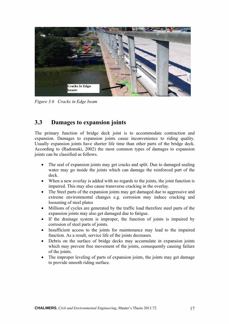
Edge beam distributes and transmits the traffic loads close to the edge of the bridge deck slab. It also supports rails and lighting towers. Cracking of edge beam occurs due to the factors explained in section 3.1.1, see figure 3.6. Furthermore, corrosion of lighting poles and railings also cause damage to the edge beams. The figure below shows the cracked edge beams of Stallbacka Bridge which were replaced in August 2010.
CHALMERS, Civil and Environmental Engineering, Master’s Thesis 2011:72 17
Figure 3.6 Cracks in Edge beam
3.3 Damages to expansion joints
The primary function of bridge deck joint is to accommodate contraction and expansion. Damages to expansion joints cause inconvenience to riding quality. Usually expansion joints have shorter life time than other parts of the bridge deck. According to (Radomski, 2002) the most common types of damages to expansion joints can be classified as follows.
The seal of expansion joints may get cracks and split. Due to damaged sealing water may go inside the joints which can damage the reinforced part of the deck.
When a new overlay is added with no regards to the joints, the joint function is impaired. This may also cause transverse cracking in the overlay.
The Steel parts of the expansion joints may get damaged due to aggressive and extreme environmental changes e.g. corrosion may induce cracking and loosening of steel plates
Millions of cycles are generated by the traffic load therefore steel parts of the expansion joints may also get damaged due to fatigue.
If the drainage system is improper, the function of joints is impaired by corrosion of steel parts of joints.
Insufficient access to the joints for maintenance may lead to the impaired function. As a result, service life of the joints decreases.
Debris on the surface of bridge decks may accumulate in expansion joints which may prevent free movement of the joints, consequently causing failure of the joints.
The improper leveling of parts of expansion joints, the joints may get damage to provide smooth riding surface.

CHALMERS, Civil and Environmental Engineering, Master’s Thesis 2011:72 18
Figure 3.7 Damaged expansion joint
3.4 Damages to railings and parapets
Damage to railings, balustrade and parapet do not directly influence the structural behavior of the bridge deck. Railings and parapet are made of different types of materials. Therefore, damages to these elements depend on construction material. Most severe damage is due impact forces caused by the collision of cars. Other damages are cracking of concrete parapet and corrosion of steel railing (Radomski, 2002).
3.5 Damages to drainage system
The efficiency of the drainage system is a major factor influencing the durability of the bridge deck. Therefore, water on the deck due to rain and snow is required to be drained off as soon as possible. Effectiveness of the drainage system depends on the working condition of all elements of the system, such as pipes, gutters, inlets and troughs, etc. The most typical types of damages to drainage system can be classified as follows (Radomski, 2002).
The accumulation of debris and other contamination cause the choking of inlets and rain water pipes. In addition, in cold regions pipes may get blocked due to accumulation of snow and ice.
The drainage system may get damage due to corrosion of the steel elements. Water leakage through the inlets may cause severe damage to the bridge deck
slab. When water is not properly drained off due to in sufficient gradient of
pavement; this may cause deterioration of the deck. Insufficient gradient of the pipes of drainage system also leads to impairment
of the drainage system. Drainage system may get damage due to mechanical damage to elements of
system.

CHALMERS, Civil and Environmental Engineering, Master’s Thesis 2011:72 19
The drainage system needs regular maintenance; lack of accessibility for maintenance leads to the impaired function and damage of the drainage system.
3.6 Damages to sealing
Sealing are used as water proving in bridge decks to reduce the permeability of concrete and to stop the chloride ingress, thereby increasing the service life of deck. Damage to sealing can be classified as follows.
Blister or bubble formation may leads to impaired function of the sealing. Delamination from concrete underlay may damage the sealing. Bad connections to expansion joints and drainage installations may also
damage the sealing. The sealing may get damage at the connection between slab and edge beam. Deterioration of overlays may damage the sealing.
3.7 Damages to pavement/overlay
The overlay provides protection to the deck against deterioration and ensures the riding quality. Thus it reduces the maintenance cost of the bridge. The overlay is exposed to environmental changes, aggressive fluids such as chlorides, carbon dioxide, de-icing salts and also the traffic load. Failure of the overlay leads to following forms of deterioration which reduces the service life of bridge structure.
CHALMERS, Civil and Environmental Engineering, Master’s Thesis 2011:72 20
4 Possible Solutions
Durability of bridge deck slabs is of major concern due to the high repair and maintenance cost. Practices should be adopted to ensure safety, security and serviceability throughout the service life. Research and development is a continuing process for the construction of more robust and durable structures.
Here, some of the key issues regarding deterioration of bridge deck slabs have been addressed such as cracking control and corrosion control.
The bridge deck is directly exposed to environmental actions such as de-icing salt, acid rains and marine environment. Thus the reinforcement is more vulnerable to attack of chlorides due to penetration of chloride ions. Corrosion of embedded reinforcement plays a critical role in limiting the service life of reinforced concrete decks and for the high maintenance costs. Therefore, there is desire of systems which show better performance under severe environmental conditions and that can be rapidly repaired. Increased concrete cover, low permeable concrete, resisting admixtures in concrete and coating on reinforcement bars is used to control the process of penetration of chloride ions, hence protecting the oxide film on the surface of reinforcement bars. In addition, a good drainage system is inevitable for the long term serviceability to avoid accumulation of water on the bridge deck. Furthermore, joints should be properly constructed and sealed to avoid leakage of water. An increase in the resistance against water intrusion into the deck slab can be achieved by using a good water proofing membrane between the concrete slab and the asphaltic layer. Following are the methods used to reduce the risk of corrosion and increase the strength of concrete against cracking.
4.1 Cathodic protection of steel reinforcement
Corrosion is an electrochemical process that requires oxygen, water and steel for chemical reactions. However, corrosion can be stopped if the access to oxygen is controlled. Design concrete practices, sealers and membranes mostly have been used to provide protection. These techniques limit the risk of corrosion to occur, but they cannot control or stop the corrosion process itself.
Cathodic protection (CP) has shown to be an effective way of reducing or eliminating corrosion of steel reinforcement. Galvanic systems and impressed current from an external source are two commonly used CP systems (Yehia & Host, 2010).
In galvanic systems, a more electronegative metal is connected to the steel to be protected. This metal acts as an anode with tendency to lose electrons. Therefore, an electric current is created between the anode and the cathode i.e. the reinforcement steel due to difference in electro negativity (Yehia & Host, 2010).
An alternative is to imply impressed current from an external power supply. A supplementary anode is then connected to reinforcement in the structure. When this anode is connected to the external power source, the steel inside the structure turns

CHALMERS, Civil and Environmental Engineering, Master’s Thesis 2011:72 21
into cathode. As long as the steel remains cathode, the rate of corrosion is very low (Clemeña & Jackson 2000).
Conductive concrete is a recent innovation and is now being used as a matrix for CP systems. Conductive concrete is a cementitious admixture having high electric conductivity. It is cast as overlay on bridge and acts as anode. The steel reinforcement in the structure acts as cathode (Yehia & Host, 2010).
4.2 Protective coating of reinforcement bars
Another method of protection from corrosion is to apply a protective coating on the surface of the reinforcement. Epoxy coating of reinforcement is the most common method used. Epoxies form a protecting and resilient film around the reinforcement and shows resistance to water, chlorides and chemicals. The coating can be damaged by mechanical abrasion, so special care and practice is required during handling and fabrication. Galvanizing of the steel is another method used for protection of reinforcement. It is achieved by coating the steel reinforcement with zinc. A tough alloy layer is formed on the steel which makes it easy to handle. A lot of research has been done and it has shown that no coating system can give guarantee for a long time of complete avoidance of corrosion of steel reinforcement in concrete. Use of stainless steel reinforcements can also reduce the risk corrosion. But Stainless steel may increase the initial cost (Yeoman, 1993).
4.3 Use of corrosion inhibitors
The use of inhibitor is another viable solution of stopping and reducing the corrosion of steel in concrete. There are two types of corrosion inhibitors. First type is Integral inhibitors which are mixed with other concrete ingredients to prevent corrosion in new construction. While second category is migrating inhibitors, which are used as treatment for existing concrete structures. Calcium nitrite is most common type of integral corrosion inhibitor. A very thin layer around the steel is formed in concrete by inhibitors, which prevents the corrosion. (Broomfield. 1997) (Bone, 2004).
Migrating inhibitors are only applied to the concrete surface. These inhibitors are used to reduce the effect of corrosion in existing concrete structures. Researchers are still unable to find the long term effectiveness of these inhibitors. The other disadvantages are material cost and difficulty lies in application (Broomfield. 1997) (Bone, 2004).
4.4 Fiber Reinforced Polymers (FRP) composites
Fiber reinforce polymer (FRP) composites have been considered for replacement of reinforcement in bridge deck slabs. Entire bridge decks can also be made of FRP composites. FRP is a new class of composite materials made of high strength fibers and resins. The fibers are typically composed of glass or carbon bounded together by a resin matrix (Benmokrane et al., 2004).

CHALMERS, Civil and Environmental Engineering, Master’s Thesis 2011:72 22
The properties of FRP vary depending on the types of fibers, fiber content, fiber orientation, fabrication process and processing conditions (Park et al., 2007). FRP composites are light weight, more durable, less corrosive, have high tensile strength and have low maintenance costs compared to conventional concrete which also make it ideal for rehabilitation. Many bridges in USA have been built using FRP reinforcement. Four bridges were constructed using FRP reinforcement and were tested under sever conditions. These bridges were found more durable in aggressive environment and have shown more competitive performance as compared to concrete bridges reinforced with steel (Benmokrane et al., 2004).
Another alternative is to make a whole deck of FRP composites. The two most common deck types used are pultruded profiles (tubular profiles) glued together or sandwich core systems. The specific deck systems are built in factories and transported to the site and glued together by adhesives. If the deck is supported by beams, composite action can be developed by cutting cavities through the deck elements to access the shear studs on the beams and then grouting these cavities. Special attention is required for joining the different parts of the FRP deck together. In experiments, FRP decks have shown very low skid resistance, good corrosion resistance and rapid installation. Epoxy or polymer modified concrete overlays provide better solution to overcome skidding effects (Sams. 2005). The major drawback is that FRP decks are initially more expensive than the decks reinforced with conventional steel and concrete.
4.5 Fiber Reinforced Concrete (FRC)
Another alternative of constructing corrosion-free bridge deck is to use fiber reinforced concrete to construct deck slabs of fiber reinforced concrete. In general, large amount of conventional steel reinforcement are needed to achieve small crack widths. As a result, larger structure dimensions are required. Also pouring of concrete becomes more difficult in case of tightly placed reinforcement. By using fiber reinforced concrete with or without ordinary steel reinforcements reduces these drawbacks. Fibers enhance the post-critical strength of concrete in terms of ductility and reduce the crack widths as shown in Figure 4.1. Fibers also reduce shrinkage in fresh concrete. The typical types of fibers used are steel fibers, glass fibers, natural fibers and synthetic fibers (e.g. polypropylene).

CHALMERS, Civil and Environmental Engineering, Master’s Thesis 2011:72 23
Figure 4.1 Tensile behavior of Fiber reinforced and normal strength concrete
In the beginning, some experiments using polypropylene fibers did not stop the corrosion of steel reinforcement. Therefore, some decks have been designed without steel reinforcement. External steel straps are provided at the bottom of such decks and are made to have composite action with superstructure through the shear connectors. Shear connectors are generally welded to steel beams. While in concrete beams extended shear stirrups act as shear connectors.
The FRC deck gains its strength from the internal compressive arching action between girders is provided by the in-plane lateral restraint. This arching action is achieved longitudinally by the restraint provided by the composite action of stiff girders and in transverse direction, external steel straps provide the restraint as shown in the Figure 4.2. Use of FRC increases the flexural, impact and fatigue strength of concrete. FRC construction cost is about 6% more than the conventional construction; however FRC increases the service life by delaying the localization of cracks and resisting the corrosion. Hence FRC minimizes the long term cost (Mufti et al., 2002) (Coughlin T., 2004).
FRC overlays with glass, metallic and plastic fibers are viable solution for the surface problems. Experiments showed that this type of reinforcement stops the crack growth originating from the overlays and leads to improve long term spalling resistance (Folliard et al., 2006).

CHALMERS, Civil and Environmental Engineering, Master’s Thesis 2011:72 24
Figure 4.2 Internal Arching Action of FRC Deck. Adapted from Coughlin (2004)
4.6 Integral abutment bridges as a possible solutions for damages with expansion joints
Expansion joint is a common part of the bridge deck slab which allows the relative movement between different parts of the bridge deck slab. However, the lifespan of the expansion joint is significantly lower than the lifespan of the bridge deck slab. Damaged expansion joints cause leakage of water to the underside of deck slab thus accelerating corrosion of reinforcement. Therefore, the expansion joints require maintenance and repair. Sometimes, the expansion joints are in very bad functional condition that it needs to be replaced. This requires extra effort in terms of money and time. Alternatively, bridges with integral abutments have the potential to be adopted as a competent solution for removing the leaking joint problem. It reduces the LCC by saving the construction cost as well as the maintenance cost (Feldmann et al, 2010).
The concept of integral abutment bridges is to connect the bridge deck slab to the abutments in such a way that the movement in the joints for expansion or contraction is ceased. Integral bridges are designed according to two basic concepts (Feldmann et al, 2010).
One of the concepts of integral bridges is constructing piles under the abutments with low flexural stiffness but sufficient vertical capacity. The reinforcement from deck slab and abutments are embedded in each other giving a monolithic connection. Long flexible piles are driven deep into the underground soil below the abutments. The piles which are embedded in the abutment make the overall bridge structure as a frame structure. Due to the long shape of the pile the frame structure behaves as flexible structure creating a hinge support between the deck slab and the abutments. In this way a low degree of restraint is achieved and the moments at the abutment corners are kept low (Feldmann et al, 2010).
The other common concept of integral bridges is constructing piles under the abutments with high flexural stiffness. The piles are stiff enough to support the higher moment at the abutment corner. As the substructure is strong so a very slender superstructure can be constructed (Feldmann et al, 2010).

CHALMERS, Civil and Environmental Engineering, Master’s Thesis 2011:72 25
4.6.1 New York State Department of Transportation's experience
The New York State Department of Transportation (NYSDOT) has constructed several integral abutment bridges since 1970s and they have shown excellent life performance (Collin et al., 2006).
According to the NYSDOT concept of integral abutment bridges, the piles with low flexural stiffness are used. However, the deck slab and the approach slab are connected by a joint without the transition of horizontal reinforcement across deck slab and approach slab. The detail design of these integral abutment bridges allows rotation of the approach slab at the abutment to accommodate any occurred settlement. To accomplish this concept the transition reinforcing bars at the joint are placed at 45° into both the deck slab and approach slab. These transition reinforcing bars are joined with the stirrups at the connection between the prestressed beam reinforcement and abutment reinforcement. According to the guide lines of NYSDOT, a maximum of 190 meters long integral abutment bridge can be constructed (Collin et al., 2006).
4.6.2 United Kingdom experience
In UK the portal frame configuration is used for the construction of integral bridges. In such a portal frame the end supports acts as retaining walls. The bridge deck beams and the supporting structure are constructed with the intention to achieve full moment continuity and accommodating the thermal expansion and contraction (Collin et al., 2006).
The designers in UK use end screen walls supported on a small number of piles or an end screen wall sitting directly on the soil or end screen wall separated from the foundation (Collin et al., 2006).
4.6.3 Swedish practices of integral abutment bridges
In Sweden, the concept of end screen walls is adopted for bridges with integral abutments. As shown in Figure End screen wall is connected with the bridge deck slab without joint and behaves as a cantilever structure. Piers are constructed to transfer the vertical forces to the ground. Sometimes bearings are used at the top of piers and sometimes not. In this way less vertical forces are transferred to the embankment soil thus reducing the risk of settlement at the approach slab (Kerokoski, 2006).
Some innovative integral abutment bridges have also been constructed in Sweden. In this concept, the piles of the integral abutment are driven below the lower edge of the back wall. The pinned connection is created between the back-wall and the piles. Then the steel tubes are placed over the piles and loosely packed sand is filled around the piles to minimize the pressure. The normal force and moment of the earth pressure

CHALMERS, Civil and Environmental Engineering, Master’s Thesis 2011:72 26
against the back wall is accommodated by creating spring elements in the specified positions (Collin et al., 2006).
In serviceability limit state, the yield strength of the steel components is used to prevent plastic deformation and decelerate the strains for delaying the collapse. The capacity in the ultimate limit state is limited by buckling and by moment/rotational capacity (Collin et al., 2006).
4.6.4 German design of integral abutment bridges
In Germany, the bridge deck slab is constructed integrally with the abutment in such manner that a frame action is created. If the bearing capacity of the soil under the abutment is high then shallow foundation is constructed just beneath the abutment wall. For soil with poor bearing capacity, piles are driven deep into the soil under the abutment walls. In both type of foundation details the aim is to acquire slender slab structure to reduce the dead weight. The abutments are connected to the bridge deck slab in such a manner that a construction joint is created which is an essential feature of frame structures. This is achieved by the proper overlap of reinforcement between the bridge deck slab and abutment (Collin et al., 2006).

CHALMERS, Civil and Environmental Engineering, Master’s Thesis 2011:72 27
5 Ultra High Performance Fiber Reinforced Concrete (UHPFRC)
Ultra High Performance Fiber Reinforced Concrete (UHPFRC) is the latest available form of advanced concrete, characterized by very low permeability, high ductility and good tensile strength in combination with high compressive strength of concrete. Principally, UHPFRC is a homogeneous, compact and ductile material. Homogeneity is obtained by removing the coarse aggregates used in Normal Strength Concrete (NSC). Compactness is obtained by using the optimum sized fine materials such as sand, silica and Superplasticizer. Ductility is obtained by using the high strength fibers. The comparison of the UHPFRC, Fiber Reinforced Concrete (FRC) and Normal Strength concrete (NSC) for uniaxial tensile and compressive stress states can be seen in Figure 5.1. It shows that the UHPFRC has a pronounce strain hardening behavior in tension, which makes it a unique concrete product (Habel, 2004). In this section this new material is presented and its potential as a future building material for Bridges is investigated.
Figure 5.1 Typical behavior of UHPFRC in a uniaxial state of stress in comparison to other concrete mixtures. Adapted from Spasojević (2008)

CHALMERS, Civil and Environmental Engineering, Master’s Thesis 2011:72 28
5.1 Historical overview
Concrete has been one of the most widely used building materials because of its high compressive strength, resistance to water and good workability. Normal Strength Concrete (NSC) is a controlled mixture of Portland cement, water, fine aggregate, coarse aggregate and air. Portland cement is a material composed of Lime (CaO), Silica (SiO2), Alumina (Al2O3) and Iron Oxide (Fe2O3). Fine aggregate is usually sand which has a chemical composition of Silica (SiO2) found in the shape of fine granular material obtained by the process of erosion of rocks. Coarse aggregate is a term used for the coarse granular material used in concrete obtained from rocks but larger in the size from sand. When cement is mixed with water it hydrates and become stiff, binding the sand and gravel into a compact solid mass. The hydration reaction results in a liquid gel. Due to the hydration process this liquid gel gets hardened and gains strength which makes concrete a vital product for construction. NSC has a Young's modulus (E) of 14 to 42 GPa. The compressive and tensile strength of NSC ranges from 12MPa and 1.6 MPa for lower class (C12/16) to 90 MPa and 5.0 MPa for the highest class (C90/105) according to Euro code 2, (BS EN 1992-1-1).
NSC has a high compressive strength but weak tensile strength. Hence, NSC is mainly used for resisting compressive stresses while reinforcement is used to resist tensile forces in structural concrete. However, the low tensile strength and brittle response in tension results in cracking. The initiation of small cracks starts at very early stage. Later on, these small cracks develop into macro cracks. Together with the low ductility this makes NSC vulnerable to environmental actions and deterioration, which results in reduced life time of the NSC structure. Regular maintenance, repair and rehabilitation are performed to achieve a consistent life performance of NSC structures. This results in higher Life Cycle Costs (LCC) for NSC structures (Rossi & Chanvillard, 2000).
Over time, there has been a struggle to overcome these drawbacks in order to improve the performance of NSC. A view of the historical development of different concrete products can be seen in the Figure 5.2. Nowadays, different types of High Performance Concrete (HPC) products are available in the market.

CHALMERS, Civil and Environmental Engineering, Master’s Thesis 2011:72 29
Figure 5.2 Historical development of Concrete. Adapted from Spasojević (2008)
UHPFRC is currently the latest advanced High Performance Concrete product. In order to get a more homogenous product course aggregates are not used in UHPFRC mixtures. The density is increased by the use of silica fume along with sand and cement, contributing to the compactness. However, due to use of large volume of fine materials the mixture becomes brittle; therefore steel fibers are added to achieve a high range of ductility. The ductile behavior of this material enables it to deform and support flexural and tensile loads, even after initial cracking. Furthermore, the almost impermeable behavior of this material contributes to the long life performance by enhancing the durability (Habel, 2004).
5.2 Composition
Research began very early for increasing both compressive and tensile strengths of concrete. The structure, composition and strength of concrete have been studied at micro and macro level. As a result, Ultra High Performance Fiber Reinforced Concrete (UHPFRC) has been evolved which is a more flexible, workable, durable and strong concrete material. It has high compressive and tensile strengths along with high ductility (Rossi & Chanvillard, 2000).
UHPFRC consists of cement, sand, silica fume content, high super plasticizer, water and fibers. The water cement ratio is maintained at 0.15 to 0.20 (Habel, 2004).
The comparison of composition and properties of Normal concrete and UHPC can be seen in the Table 5.1.

CHALMERS, Civil and Environmental Engineering, Master’s Thesis 2011:72 30
Table 5.1. Comparison of composition and properties of NSC and UHPFRC. Adapted from Spasojević (2008)
5.2.1 Cement
The cement content used is larger than 700 kg/m3. The amount of cement is two times higher than in NSC. The quality of cement used should have low alkali content to avoid ettringite formation and reduce the heat of hydration (Habel, 2004).
The higher volume of cement reduces the heterogeneity and there are fewer pores in the concrete, resulting in lower internal restraint forces due to plastic shrinkage compared to NSC (Spasojević, 2008).
Mat
rix
com
pos
itio
n
NSC UHPFRC
Component Kg/m3 Kg/m3
Portland cement <400 700-1000
Coarse aggregate ≈1000 0-200
Fine aggregate ≈700 1000-2000
Silica fume - 200-300
Superplasticizer - 10-40
water >200 110-200
Water-cement ratio >0.35 <0.24
Reinforcement/Fibers (kg/m3) No Fibers >150
Pro
per
ties
Density (kg/m3) 2000-2800 >2500
Compressive strength (MPa) <60 >150
Tensile strength (MPa) <3 >8
Modulus of elasticity (GPa) ≈30 50-70
Fracture energy (J/m2) 30-200 >10000

CHALMERS, Civil and Environmental Engineering, Master’s Thesis 2011:72 31
5.2.2 Sand
Quartz is recommended as fine aggregate which increases the compressive strength of UHPFRC. The optimum size used is less than 1 mm. however, an optimized grain size distribution should be obtained between cement, sand and silica fume to achieve good compactness and very low permeability. It enhances the stiffness and smoothen the overall texture of the hardened material. It also contributes to the high density of the product (Habel, 2004).
5.2.3 Silica fume
The content of silica fume used is 25% of the cement content. The use of silica fume is very useful to fill the voids and by forming a denser hydration product. It enhances the compactness and mechanical strength (Habel, 2004).
Silica fume acts as filler by filling the pores between the cement particles, making the UHPFRC an almost impermeable material compared to NSC (which has 20-25% pores). In addition, it reacts chemically with cement forming the dense cement gel compound resulting in well developed bond, which increases the mechanical properties. It also increases the viscosity of the UHPFRC which makes the mix a self compacting material (Spasojević, 2008).
5.2.4 Superplasticizer
Polycarboxylates and polycarboxylatethers are used as Superplasticizer for good workability. High efficiency is achieved as it has low water cement ratio compatibility (Habel, 2004).
5.2.5 Fibers
The use of fibers in UHPFRC increases the strength and ductility of concrete by delaying the process of localization of cracks and bridging the cracks. Thus, improving the post cracking behaviour of UHPFRC by introducing strain hardening (Rossi & Chanvillard, 2000).
Different types of fibers are used, characterized by their material, size and shape. Both steel and synthetic fibers are used to meet the requirement on strength and stiffness. On the market, the available steel fibers have a modulus of elasticity of 200 GPa and the strength is in the range of 1000 - 3000 MPa. Such high strength fibers are essential to transfer the tensile forces between small cracks safely. Different fibers are available with respect to shape and size. The prominent used fibers are short and straight fibers, and long fibers with hooked ends (Spasojević, 2008). However, the size and amount of fibers used depend on the need for ductility and workability. Usually, short fibers, long fibers or a mixture of both short and long fibers of metal or steel is used (Habel, 2004). The size and amount of metal fibers has a great influence on the mechanical behavior of the concrete structure and in particular the crack formation and crack propagation. A large amount of short fibers are useful in the crack initiation stage.

CHALMERS, Civil and Environmental Engineering, Master’s Thesis 2011:72 32
While in case of macro cracks the small amount of long fibers are useful (Rossi & Chanvillard, 2000).
5.3 Types of UHPFRC
There are different types of UHPFRC materials available on the market, differing mainly regarding their mixture composition. Mainly there are three types of UHPFRC mixtures which are Compact Reinforced Composites (CRC), Reactive Powder Concrete (RPC) and Multi-Scale Fiber Reinforced Concrete (MSFRC). Following the idea of these three types, different brands of UHPFRC are available on the market, developed by different companies. The modification has been done in these three types according to the composition of the mixture. The bending tensile strength of Compact Reinforced Composite (CRC) is much higher compared with other types of UHPFRC because of the use of conventional concrete. Its bending tensile strength has been obtained by using four points bending tensile test, while the bending tensile strengths of other brands is achieved by uni-axial tensile test (Rossi & Chanvillard, 2000).
Different types of UHPFRC materials and brands are listed and described in the Table 5.2 below.
Table 5.2 Mechanical prosperities of different type of UHPFRC. Adapted from CRC Tech (2011, Richard & Cheyrezy (1995), Rossi & Chanvillard (2000), ductal-lafarge (2011), Rossi (2008), Spasojević (2008)
Mechanical properties CRC RPC Ductal® CEMTECmultiscale® BSI®
Compressive strength
(MPa) 140-400
200-800
150-200 180 190
Bending tensile strength
(MPa)
30-200 30-50 25-40 25 9
Young's Modulus
(GPa) 40-80 50-60 50-55 50 60
Density
(kg/m3)
2600-3000
2500 2500 2700
Compact Reinforced Composite (CRC)

CHALMERS, Civil and Environmental Engineering, Master’s Thesis 2011:72 33
One of the UHPFRC types is called Compact Reinforced Composite (CRC) and was developed by the company Aalborg Portland in Denmark. It consists of high percentage of conventional reinforcement and short sized strong metal fibers. CRC contains 5 to 10% of 6 mm long and 0.15 mm diameter metal fibers. The high percentage of conventional reinforcement increases the ductility of the material but is, on the other hand, more vulnerable to formation of cracks because of the stress concentration around the conventional reinforcement. In order to control the large number of cracks short fibers are used. However, it is pretty hard to install the large amount of conventional reinforcement as it is time consuming and requires extra skill and labour (Rossi & Chanvillard, 2000).
The four points bending tensile test shows a very high range of tensile strength for CRC. It is because of the use of closely spaced conventional reinforcement along with metal fibers which makes the CRC structure extremely ductile. The water/powder ratio is in the range of 0.15 to 0.20 which makes the wet mixture a self compacting material. The durability of CRC is very high compared to NSC. Practically it has very less amount of pores which makes it almost impermeable material. Non-existence of pores means, no water inside the CRC structure. Therefore no freeze and thaw problem is found in CRC structures. The mechanical properties of CRC are briefed as shown in Table 5.2 (CRC Tech, 2011).
Reactive Powder Concrete (RPC)
Another type of UHPFRC is called Reactive Powder Concrete (RPC), developed by a company called Bouygues in France. It consists of fibers twice the length and half the percentage of CRC. RPC contains a maximum of 2.5% of 13 mm long and 0.16 mm diameter metal fibers with water/powder ratio of 0.15 to 0.19. Due to less amount of fibers used in RPC, the uniaxial tensile strength is confound to 8 MPa only. With such a low amount of fibers the post cracking behavior was variable. However, if the orientation of the fibers is kept orthotropic, perpendicular to the flexural cracks, than a homogenous and ductile product can be obtained (Rossi & Chanvillard, 2000). Two types of RPC products are used depending on their compressive strength. One is RPC 200 which has a compressive strength of 200 MPa and other is RPC 800 which has a maximum compressive strength of 800MPa. A compressive strength of 800 MPa is achieved by using steel aggregates instead of quartz sand and applying a pre-heated pressure of 50 MPa. The mechanical properties of RPC are briefed as shown in Table 5.2 (Richard & Cheyrezy, 1995).
Multi-Scale Fiber Reinforced Concrete (MSFRC)
Further development showed another type of UHPFRC called Multi-Scale Fiber Reinforced Concrete (MSFRC) developed by the Laboratoire Central Des Ponts et Chaussées (LCPC) in France. It consists of both short and long sized fibers. The amount of short fibers used in this mixture is 5 % which are straight in shape, having length of 5 mm and 0.25 mm in diameter. 2% of hooked end long fibers with 25 mm length and 0.30 in diameter are used. Because of the mixed use of short and long fibers it gives good results for workability, ductility and tensile strength (Rossi & Chanvillard, 2000).

CHALMERS, Civil and Environmental Engineering, Master’s Thesis 2011:72 34
Ductal®
Ductal® is a high strength ductile UHPFRC product developed by Lafarge, Bouygues and Rhodia in France. This is obtained by using the idea of RPC. It consists of 2% of 12 mm long and 0.2 mm diameter fibers with water/cement ratio of 0.20 to 0.26. There are two types of fibers used in Ductal® that is High Carbon Metallic or Poly-Vinyl Alcohol (PVA) fibers. With the use of this technology thinner, lighter and more graceful structures can be made having good ductility and less permeability. It has a very low porosity compared to NSC which makes the Ductal® an almost impermeable material. The mechanical properties can be seen in the table 5.2 (ductal-lafarge, 2011). The amount of fibers used in this product is very less compared to other types of UHPFRC. With the use of hooked and twisted shaped high strength fibers the same strain hardening behavior can be obtained as the other UHPFRC product exhibit with 5 to 10 % fibers (Kim et al. 2008).
CEMTECmultiscale®
CEMTECmultiscale® is a type of UHPFRC introduced in France. This is obtained by
using the idea of MSFRC. It contains 11% fiber with the ranging from shorter than 1 mm up to 20 mm long (Rossi, 2008). The mechanical properties can be seen in the Table 5.2.
Béton Special Industriel (BSI®)
BSI® (Béton Special Industriel) is a type of UHPFRC developed by the company EIFFAGE in collaboration with cement manufacturer SIKA in France. It contains 2.5 % fibers with water/cement ratio of 0.22. With correct casting procedure, the required strain-hardening behavior of typical UHPFRC can be obtained in spite of use of such low quantity of fibers (Spasojević, 2008). The mechanical properties can be seen in the Table 5.2.
5.4 Properties of fresh UHPFRC
5.4.1 Workability
UHPFRC has the advantageous property of being self-compacting. To achieve this behavior, the mixture should be design in such a way that it gets good workability. However, the composition of the UHPFRC mixture should be selected in such a way that the basic characteristics of homogeneity, compactness and ductility should not be compromised.
The required workability can be obtained in a controlled environment for pre-cast UHPFRC materials. However, to use UHPFRC as cast-in-situ construction material for bridges, the workability issue should be addressed with a much realistic approach.

CHALMERS, Civil and Environmental Engineering, Master’s Thesis 2011:72 35
As there is low amount of water used in UHPFRC, therefore, the amount of cement, silica, Superplasticizer and fibers should be selected in such a proportion to achieve the required workability along with strength and ductility (Habel, 2004).
Addition of super plasticizers enhances the workability of the UHPFRC mixture. Superplasticizer is added in UHPFRC mixture before and also after addition of water. A step wise addition of Superplasticizer enhances the fluidity of UHPFRC mixture. It also reduces the viscosity of the UHPFRC mixture lowering the air content (Tue at al. 2008).
5.4.2 Hydration and heat generation
Hydration is the exothermic process in which reaction of Portland cement with water and reaction of additives such as silica fume takes place. The degree of hydration is defined as the ratio between the amount of cement or binders hydrated to the initial amount of cement or binder.
UHPFRC consist of very low water cement ratio which delays the full hydration of cement contents Habel K. (2004). As an example UHPFRC with water cement ratio of 0.18 and with 26% amount of silica fume showed a 31% final degree of hydration.
Figure 5.3 Evolution of the degree of hydration of UHPFRC and NSC. Adapted from Habel (2004).
In the fig above, there is a long dormant period typically for 24 hours or long due to addition of super plasticizers which delay hardening of concrete. Then strong hydration reaction starts and heat is released. There is increase in degree of hydration between 30 and 57 hours for UHPFRC. While for normal strength concrete there is small dormant period of 2 to 4 hours. After this stage cement starts to hydrate and releases heat. Final stage of hydration finishes either with complete hydration or unhydrated cement left when no water is available for hydration. In the previous

CHALMERS, Civil and Environmental Engineering, Master’s Thesis 2011:72 36
researches a model was proposed for hydration of normal strength concrete that only complete hydration of cement content can occur if water-cement ratio is of 0.42 Denarié et al. (2009). Later Habel (2004) used this model for predicting the degree of hydration of UHPFRC. Furthermore, it was also shown that the degree of hydration of UHPFRC is very low and cement content of UHPFRC does not hydrate completely.
In 2004, Habel conducted semi-adiabatic tests on UHPFRC to find the temperature generated during hydration. Figure 5.4 shows that temperature of UHPFRC is constant until 24 hours and rapidly increases until 36 hours after mixing. However after that temperature becomes slow down and finally temperature reaches between 100oC to 120oC. The initial dormant period is due to use of super plasticizer. While dormant period is shorter in normal strength concrete and evolution of heat is also less than UHPFRC. Hydration of UHPFRC releases almost double the amount of heat released by normal strength concrete (Habel, 2004).
Figure 5.4 Temperature rise in UHPFRC and Normal concrete during hydration. Adapted from Habel (2004).
5.4.3 Self dessication
One of the detrimental effects of using low water/cement ratio in UHPFRC is self dessication. In this process, concrete becomes dry from inside due to the consumption of moisture during the hydration reactions. The result is that the hydration of the concrete terminates if addition moisture is not provided creating empty capillary porosities within cement paste micro structures, which can affect the durability properties of UHPFRC. However, detrimental effects can be controlled by special attention to curing (Carino & Meeks, 1999).

CHALMERS, Civil and Environmental Engineering, Master’s Thesis 2011:72 37
5.5 Material properties for the hardened UHPFRC
5.5.1 Permeability
Bridge deck slabs and their connecting elements are among the most vulnerable to chloride ingression. Deterioration due to corrosion of reinforcement is the most common problem with these structures. Moreover, the transport of chloride and oxygen inside the cracks also facilitates the process of corrosion. UHPFRC presents a very low permeability which makes it an attractive construction material to be used in structures exposed to water and aggressive solutions. Therefore UHPFRC may be used as construction material to control the corrosion deterioration in such susceptible areas. UHPFRC not only provides protection but also enhances the load carrying capacity of the structure (Charron et al., 2006). To study the permeability of UHPFRC under high stresses, one of the researches has been conducted at the Swiss Federal Institute of Technology (EPFL). Uni-axial tensile and permeability tests were conducted on the UHPFRC called CEMTECmultiscale
®. The specimens were cured for 28 days and Uni-axial tensile tests were carried out to get desire deformation of 0.13, 0.25, 0.5, 0.75 and 1%.
Table 5.3 Constituents of UHPFRC specimen. Adapted from Charron et al. (2006).
Component Content (kg/m3)
Cement-CEMI 52.5 1051
Silica fume 273
Sand (dmax=0.5 mm) 733
Steel fibers (l/d=50) 468
Water 165
Super-plasticizer 35
W/binder ratio 0.140
It was also observed that cracking did not influence equivalent water permeability of core specimen significantly until deflection of Єt = 0.13 mm for 100 mm specimen and for NSC it was 0.05 mm. Furthermore, the permeability of uncracked UHPFRC was found 1× 10⁻¹⁰cm/s and for NSC it was found 5 × 10⁻⁹cm/s. This difference between is due to multiple micro-cracking in UHPFRC instead of few micro-cracks develop in NSC. While micro-cracks are less permeable than discrete cracks in normal strength concrete (Charron et al., 2006). .
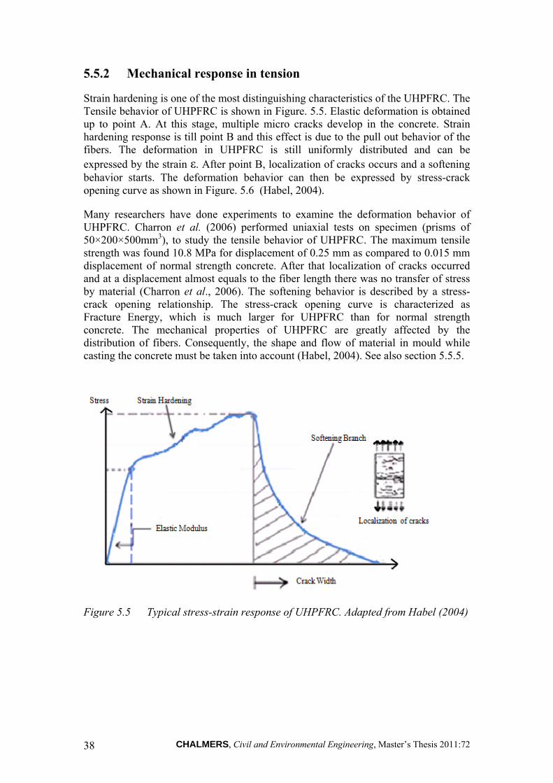
CHALMERS, Civil and Environmental Engineering, Master’s Thesis 2011:72 38
5.5.2 Mechanical response in tension
Strain hardening is one of the most distinguishing characteristics of the UHPFRC. The Tensile behavior of UHPFRC is shown in Figure. 5.5. Elastic deformation is obtained up to point A. At this stage, multiple micro cracks develop in the concrete. Strain hardening response is till point B and this effect is due to the pull out behavior of the fibers. The deformation in UHPFRC is still uniformly distributed and can be expressed by the strain ε. After point B, localization of cracks occurs and a softening behavior starts. The deformation behavior can then be expressed by stress-crack opening curve as shown in Figure. 5.6 (Habel, 2004).
Many researchers have done experiments to examine the deformation behavior of UHPFRC. Charron et al. (2006) performed uniaxial tests on specimen (prisms of 50×200×500mm3), to study the tensile behavior of UHPFRC. The maximum tensile strength was found 10.8 MPa for displacement of 0.25 mm as compared to 0.015 mm displacement of normal strength concrete. After that localization of cracks occurred and at a displacement almost equals to the fiber length there was no transfer of stress by material (Charron et al., 2006). The softening behavior is described by a stress-crack opening relationship. The stress-crack opening curve is characterized as Fracture Energy, which is much larger for UHPFRC than for normal strength concrete. The mechanical properties of UHPFRC are greatly affected by the distribution of fibers. Consequently, the shape and flow of material in mould while casting the concrete must be taken into account (Habel, 2004). See also section 5.5.5.
Figure 5.5 Typical stress-strain response of UHPFRC. Adapted from Habel (2004)

CHALMERS, Civil and Environmental Engineering, Master’s Thesis 2011:72 39
(a) (b)
Figure 5.6 (a) Shear-Strain response before crack localization and (b) Stress-crack opening response after localization
The load displacement relationship from a tensile test cannot be directly translated into stress–strain relationship because of the localization of cracks after maximum load as shown in figure 5.7. Instead materials properties should be divided into an elastic stress-strain relation and a stress crack opening relation. In normal strength concrete, after crack initiation the deformation increases while the material becomes unloaded (Plos, 2000). In case of UHPFRC, a large number of micro cracks develop in the concrete after the crack initiation. This stage is called strain hardening and is a major principal difference in response, distinguishing its tensile behavior from normal strength concrete.
5.5.3 Mechanical response in compression
UHPFRC has a compressive strength of more than 150 MPa and shows a ductile post-peak behavior due to stress-transfer mechanism of the micro cracks. The elasticity modulus, E is in range of 50-70 GPa. Ultra High Performance concrete (UHPC) shows brittle behavior under compression, but addition of fibers impairs the effect of the brittle behavior and also increases the compressive strength as shown in Figure 5.7 (Spasojević, 2008).
The post peak behavior is affected by the aspect ratio of fibers (lf/df), fibers orientation, shape of fibers and, bond between fibers and matrix (Spasojević, 2008)(Denarié, 2009).
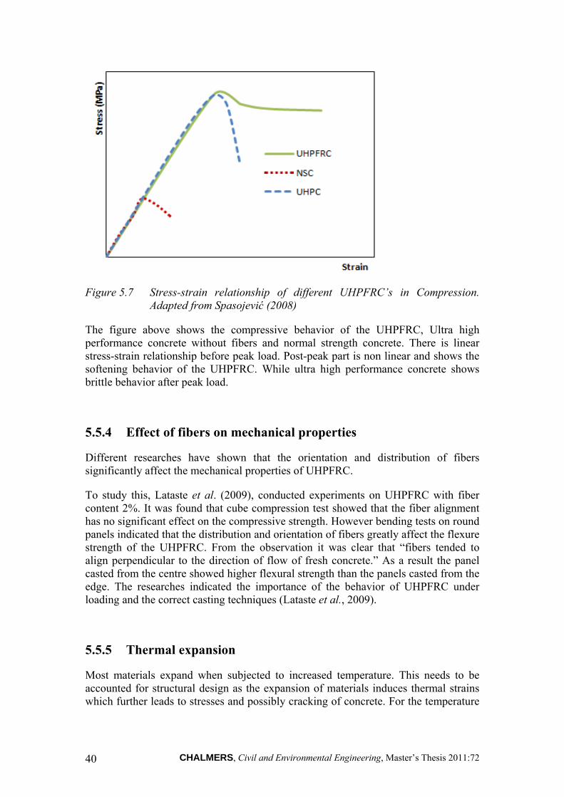
CHALMERS, Civil and Environmental Engineering, Master’s Thesis 2011:72 40
Figure 5.7 Stress-strain relationship of different UHPFRC’s in Compression. Adapted from Spasojević (2008)
The figure above shows the compressive behavior of the UHPFRC, Ultra high performance concrete without fibers and normal strength concrete. There is linear stress-strain relationship before peak load. Post-peak part is non linear and shows the softening behavior of the UHPFRC. While ultra high performance concrete shows brittle behavior after peak load.
5.5.4 Effect of fibers on mechanical properties
Different researches have shown that the orientation and distribution of fibers significantly affect the mechanical properties of UHPFRC.
To study this, Lataste et al. (2009), conducted experiments on UHPFRC with fiber content 2%. It was found that cube compression test showed that the fiber alignment has no significant effect on the compressive strength. However bending tests on round panels indicated that the distribution and orientation of fibers greatly affect the flexure strength of the UHPFRC. From the observation it was clear that “fibers tended to align perpendicular to the direction of flow of fresh concrete.” As a result the panel casted from the centre showed higher flexural strength than the panels casted from the edge. The researches indicated the importance of the behavior of UHPFRC under loading and the correct casting techniques (Lataste et al., 2009).
5.5.5 Thermal expansion
Most materials expand when subjected to increased temperature. This needs to be accounted for structural design as the expansion of materials induces thermal strains which further leads to stresses and possibly cracking of concrete. For the temperature
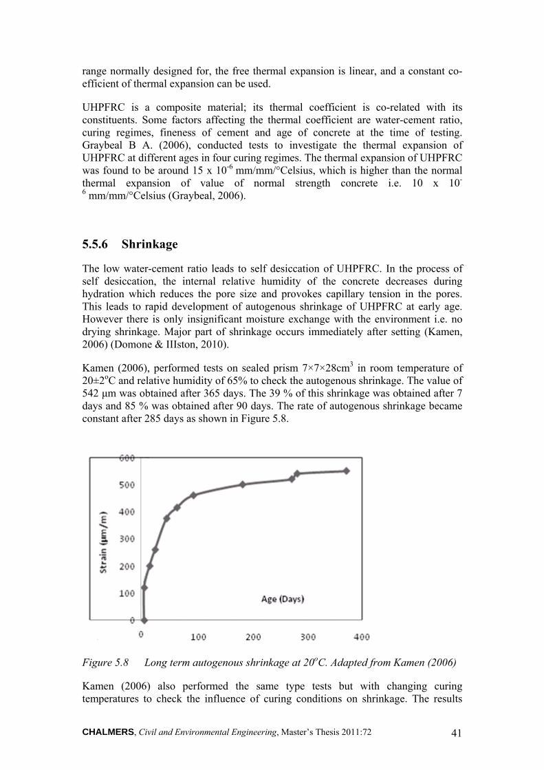
CHALMERS, Civil and Environmental Engineering, Master’s Thesis 2011:72 41
range normally designed for, the free thermal expansion is linear, and a constant co-efficient of thermal expansion can be used.
UHPFRC is a composite material; its thermal coefficient is co-related with its constituents. Some factors affecting the thermal coefficient are water-cement ratio, curing regimes, fineness of cement and age of concrete at the time of testing. Graybeal B A. (2006), conducted tests to investigate the thermal expansion of UHPFRC at different ages in four curing regimes. The thermal expansion of UHPFRC was found to be around 15 x 10-6 mm/mm/°Celsius, which is higher than the normal thermal expansion of value of normal strength concrete i.e. 10 x 10-
6 mm/mm/°Celsius (Graybeal, 2006).
5.5.6 Shrinkage
The low water-cement ratio leads to self desiccation of UHPFRC. In the process of self desiccation, the internal relative humidity of the concrete decreases during hydration which reduces the pore size and provokes capillary tension in the pores. This leads to rapid development of autogenous shrinkage of UHPFRC at early age. However there is only insignificant moisture exchange with the environment i.e. no drying shrinkage. Major part of shrinkage occurs immediately after setting (Kamen, 2006) (Domone & IIIston, 2010).
Kamen (2006), performed tests on sealed prism 7×7×28cm3 in room temperature of 20±2oC and relative humidity of 65% to check the autogenous shrinkage. The value of 542 μm was obtained after 365 days. The 39 % of this shrinkage was obtained after 7 days and 85 % was obtained after 90 days. The rate of autogenous shrinkage became constant after 285 days as shown in Figure 5.8.
Figure 5.8 Long term autogenous shrinkage at 20oC. Adapted from Kamen (2006)
Kamen (2006) also performed the same type tests but with changing curing temperatures to check the influence of curing conditions on shrinkage. The results

CHALMERS, Civil and Environmental Engineering, Master’s Thesis 2011:72 42
indicate the increase of autogenous shrinkage with increasing curing temperature as shown in Figure 5.9.
Figure 5.9 Autogenous Shrinkage for various curing conditions. Adapted from Kamen (2006)
The presence of fibers in the UHPFRC reduced the shrinkage deformation to 35% as compared to a matrix of ultra high performance concrete as shown in Figure 5.10.
Figure 5.10 The influence of fibers on shrinkage in UHPFRC with and without fibers. Adapted from Kamen (2006)
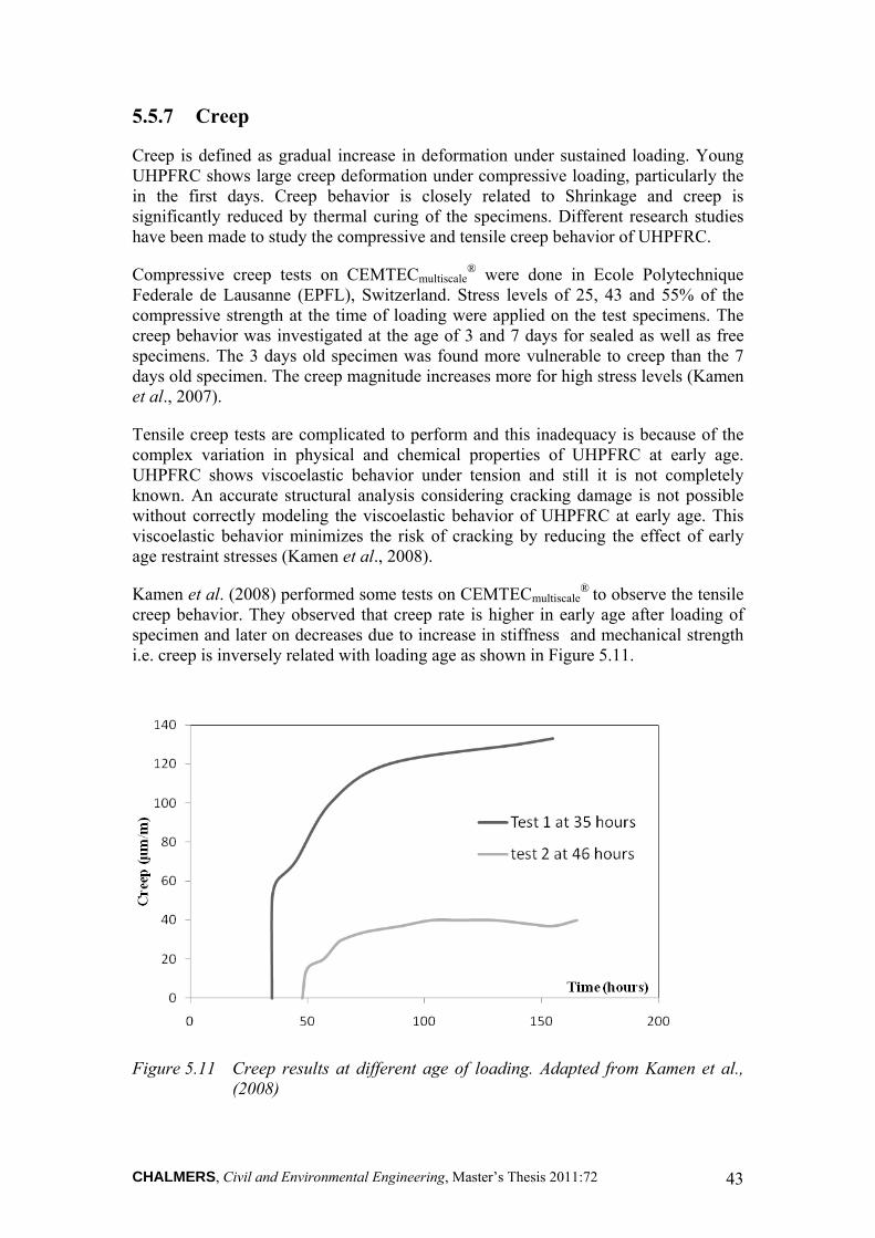
CHALMERS, Civil and Environmental Engineering, Master’s Thesis 2011:72 43
5.5.7 Creep
Creep is defined as gradual increase in deformation under sustained loading. Young UHPFRC shows large creep deformation under compressive loading, particularly the in the first days. Creep behavior is closely related to Shrinkage and creep is significantly reduced by thermal curing of the specimens. Different research studies have been made to study the compressive and tensile creep behavior of UHPFRC.
Compressive creep tests on CEMTECmultiscale® were done in Ecole Polytechnique
Federale de Lausanne (EPFL), Switzerland. Stress levels of 25, 43 and 55% of the compressive strength at the time of loading were applied on the test specimens. The creep behavior was investigated at the age of 3 and 7 days for sealed as well as free specimens. The 3 days old specimen was found more vulnerable to creep than the 7 days old specimen. The creep magnitude increases more for high stress levels (Kamen et al., 2007).
Tensile creep tests are complicated to perform and this inadequacy is because of the complex variation in physical and chemical properties of UHPFRC at early age. UHPFRC shows viscoelastic behavior under tension and still it is not completely known. An accurate structural analysis considering cracking damage is not possible without correctly modeling the viscoelastic behavior of UHPFRC at early age. This viscoelastic behavior minimizes the risk of cracking by reducing the effect of early age restraint stresses (Kamen et al., 2008).
Kamen et al. (2008) performed some tests on CEMTECmultiscale® to observe the tensile
creep behavior. They observed that creep rate is higher in early age after loading of specimen and later on decreases due to increase in stiffness and mechanical strength i.e. creep is inversely related with loading age as shown in Figure 5.11.
Figure 5.11 Creep results at different age of loading. Adapted from Kamen et al., (2008)

CHALMERS, Civil and Environmental Engineering, Master’s Thesis 2011:72 44
In the above figure creep behavior of two CEMTECmultiscale® specimens is shown.
Creep rate is higher for 35 hours than 46 hours. From the tests results on CEMTECmultiscale
®, it was observed that that shrinkage almost stops after 90 days and viscoelastic behavior stabilizes afterwards. It is due to hydration reaction is shorter for UHPFRC due to self desiccation (Habel K., 2004).
5.5.8 Fatigue behavior
Fatigue is defined as the process of internal structural changes in a material under cyclic loading. It can be a possible failure mechanism for a structure subjected to repeated loading. Such as bridge deck slab which is subjected to the repeated load of traffic and the understanding of fatigue bending behavior is important.
NSC is more prone to fatigue failure due to its heterogeneous structure. It has pores, air voids, and trapped water content in the pores, freeze and thaw cycles and low resistance to tensile loading. The fatigue mechanism can be divided into three steps for NSC. First is the crack initiation stage, second is the crack propagation stage in which the formation of microcracks occurs and third is the failure stage in which the formation of macrocracks occurs. Furthermore, NSC exhibits no fatigue limit under the threshold limit of 2×10⁶ cycles. Hence there is no known stress level below which the fatigue life of plain concrete will be infinite (Lee and Barr, 2004).
However, UHPFRC is much stronger material than NSC, in terms of, mechanical behavior and durability properties. Therefore, it is expected that UHPFRC will show better performance to fatigue loading than NSC when used as construction material for bridge deck slabs. In the second stage crack propagation causes the localization of microcracks. Hence, efforts can be done to retard crack growth in this stage. One of the possibilities is adding the fibers which will bridge these small cracks, inhibit the crack growth and increase the load carrying capacity of UHPFRC. It has been found that UHPFRC shows large number of small cracks under static loading, which is a bright characteristic of UHPFRC due to the addition of fibers, as; it is the aim of the designer to avoid formation of the large cracks during Serviceability Limit State (SLS). It seems from observations that UHPFRC shows better performance in the fatigue life under flexural fatigue loading than compressive fatigue life under compressive fatigue loading. It may be possible due to the bridging of cracks under tensile loading (Lee and Barr, 2004).
However, it has been found that UHPFRC undergo larger strains before failure than NSC. UHPFRC shows higher level of damage under static and fatigue testing. It has been also suggested that fibers enhances the fatigue behavior of UHPFRC under low cyclic loading only that is up to 103 cycles, approximately. Unlike NSC which has no fatigue limit, UHPFRC reaches a fatigue limit of 2×10⁶ cycles. However, it is not confirmed yet that what the fatigue limit of UHPFRC is (Lee and Barr, 2004).
UHPFRC shows different behavior in fatigue loading compared to NSC. The response of UHPFRC is studied under uni-axial loading as it can be seen in the Figure 5.12. Figure 5.14 shows the development of strain versus number of cycles to failure under uni-axial. The response is divided into 3 phases based on the strain development. In phase I, the strain develops non-linearly up to 3% to 5% of the number of cycles to

CHALMERS, Civil and Environmental Engineering, Master’s Thesis 2011:72 45
failure. In phase II, which is from 5% to 95% the strain increases linearly. And in the last phase the structure fails verified by rupture behavior. However, In NSC the linearity starts at 20% and rupture at 80%. Due to fibers in UHPFRC the damage process is slow and less brittle than NSC (Gunberg et al., 2008).
Figure 5.12 Development of strain vs number of cycles to failure for UHPFRC and NSC under fatigue loading. Adapted from Grunberg et al. (2008)
5.6 Durability properties
Durable concrete is defined as being able to resist weathering, chemical attacks, abrasion and other processes of deterioration. UHPFRC has much denser structure than ordinary concrete therefore it shows high durability due to significant reduction in pore size and volume. Pore volume ratio of capillary pores of UHPFRC is 4.3 -4.5%, where for high strength concrete is 9% (Toutlemonde & Resplendino, 2011). Various researches have been done to determine the durability of UHPFRC in aggressive environments. In 2007, Graybeal and Tanesi made a research on the material property characterization of UHPFRC with 2 % fiber contents. They conducted durability tests on UHPFRC in four different curing conditions.
These curing regimes were steam curing in which specimens were steam cured in 90o C for four days continuously, 2nd was normal curing method in which no extra heat treatment was applied, 3rd was tempered steam n which specimens were treated in 60o C and last was delayed steam in which specimens were steam cured after 15 days. For in-situ bridge construction usually concrete is cured by ordinary curing methods.

CHALMERS, Civil and Environmental Engineering, Master’s Thesis 2011:72 46
5.6.1 Chloride penetration
Chloride ingress by diffusion or capillary suction causes corrosion of reinforcement in reinforced concrete. Permeability of the concrete plays an important role to stop the migration of chloride ions.
Graybeal and Tanesi (2007) have performed tests on UHPFRC having low w/b ratio and densely packed matrix, to find its ability to resist chloride ion penetration. Specimens were tested in sodium chloride and sodium hydroxide solutions. Electric potential was applied across a specimen load cell and the amount of current passing through the specimen was measured. It was found that UHPFRC has almost negligible chloride ion penetration when treated thermally and showed very low penetration when non-thermally treated. Normal strength concrete with 0.4 to 0.6 water-cement ratio showed high penetration of chloride ions as compared to UHPFRC as shown in table 5.5.
5.6.2 Freeze –Thaw resistance
Continuous freezing and thawing of saturated concrete leads to disintegration of concrete. Since water expands 9% when it freezes it will create hydraulic pressure inside the pore structure causing the expansion of concrete. This can eventually leads to cracking of concrete. The effect of Freeze-thaw cycles can be prevented by air entrainment or by using concrete with low w/c ratio.
Concrete requires extended durability in Swedish environmental conditions. UHPFRC contains very fine particles of binders and silica fume, which makes it almost impermeable as compared to normal strength concrete. Furthermore UHPFRC has a high tensile strength. Consequently it can be expected to have good resistance with respect to freeze-thaw cycles. A test series according to ASTM was performed on UHPFRC which was subjected to freeze-thaw cycles (Graybeal and Tanesi, 2007). In total 690 freeze-thaw cycles were applied on the specimens during 9 months. Over all the results confirmed the durability of UHPFRC under freeze-thaw conditions. Other researchers have shown 100% durability of UHPFRC when subjected to 300 freeze-thaw cycles (Habel et al., 2008).
5.6.3 Alkali Silica Reaction
The reaction of alkalies in the cement with silica causes expansion of concrete, which later on may leads to cracking. Alkalies can also be contributed from admixtures and de-icing salts. In the presence of moisture, internal reaction takes place, causing disintegration of the concrete matrix.
Graybeal (2006) performed tests on specimens of UHPFRC according to ASTM to detect the possible effects of alkali silica reaction. In these tests, the specimens were subjected to different curing conditions. Then the specimens were placed in a sodium hydroxide solution in 80oC. The expansion of the specimens was measured less than 0.1% after 14 days and less than the threshold value of 0.2% according to after 28

CHALMERS, Civil and Environmental Engineering, Master’s Thesis 2011:72 47
days. Alkali silica reaction needs water for completion in any concrete. However, due to the low permeability alkali silica reaction will stop when no water is available and it is harmless to UHPFRC. Furthermore, the curing conditions affect the ASR as shown in the results in Table 5.4. For more details see Graybeal and Tanesi, 2007.
Table 5.4 ASTM Alkali-Silica expansion results and chloride ion permeability for different curing regimes. Adapted from Graybeal (2006), Graybeal and Tanesi (2007)
Curing Regime
14 days Expansion (%)
28 days Expansion
(%)
Coulomb’s Passed
(Average)
Chloride Ion Permeability
Average Average
Steam
Air (Standard)
Normal Strength Concrete (water-cement 0.4-0.6)
Tempered Steam
Delayed Steam
0.013
0.011
0.005
0.001
0.009
0.012
0.004
0.002
18
360
2000-4000
39
18
Negligible
Very Low
High
Negligible
Negligible
5.6.4 Abrasion resistance
Abrasion is a form of deterioration caused mostly by studded tires and blades of snow clearing vehicles. To know the abrasion resistance of UHPFRC tests were conducted by Graybeal (2006), according to standards of ASTM. In this test a cutter with dressing wheels mounting on a rod is rotated on a specimen and the amount of concrete abraded is measured, which gives the resistance of the specimen to abrasion. Tests were conducted on three different concrete surfaces. It was found that thermally treated specimens lost between 0.1 to 0.3 grams of from total mass during abrasion. While thermally untreated specimens lost 1 –3 grams of mass. Furthermore, the finishing of the surface also modifies the abrasion resistance as shown in Figure 5.13. It was also observed that UHPFRC shows more abrasion resistance prior to the rupture of smooth cast surface while high performance fiber concrete shows constant abrasion resistance throughout during the test (Graybeal, 2006).

CHALMERS, Civil and Environmental Engineering, Master’s Thesis 2011:72 48
Figure 5.13 The chart shows the average weight loss (grams) per abrading under different curing conditions. Adapted from Graybeal (2006).
The figure above shows the weight loss of three concrete surfaces (finished under steel cast surface, sand blasted surface, and ground surface) in different curing regimes. The concrete finished under steel cast surface and cured with delayed steam shows the least value of abrasion as compared to other concrete specimens.

CHALMERS, Civil and Environmental Engineering, Master’s Thesis 2011:72 49
6 Application of UHPFRC to Bridge Decks
Bridge decks all over the world are facing increasing deterioration problems due to aggressive environment and de-icing salt. This leads to costly repair interventions that disturbs traffic and results in high life cycle cost for the bridges. Over the last few decades, considerable efforts have been made to improve the resistance of bridge decks against deterioration. UHPFRC is characterized by excellent mechanical properties and very low permeability which makes it a very suitable material to be used in aggressive environments. UHPFRC can be used as a construction material for new structures as well as for rehabilitation of existing structures. Composite UHPFRC structures provide long term durability, thus reducing the maintenance cost.
The superstructure as well as the substructure of shorter span bridges is usually constructed of concrete. This results in good aesthetical appearance keeping the construction cost low. For longer spans, it is common with composite bridges, combining steel girders with a concrete bridge deck and a concrete substructure. Concrete bridge deck with longer span is an important challenge because of the heavy weight of the concrete deck. UHPFRC exhibits excellent performance with respect to ductility combined with high compressive and bending strength. Therefore, UHPFRC can be used as a construction material for such bridge deck slabs adopting a slender section. Furthermore, low permeability in combination with durability makes it suitable to use as a protective overlay to the bridge deck slab. Also very good bonding properties of UHPFRC to reinforcing bars make it suitable for joining concrete elements that should act as one unit.
6.1 Rehabilitation with UHPFRC
The successful rehabilitation of existing structures is a big challenge to civil engineers because, when a new concrete layer is applied to an old concrete structure, a composite structure is formed. Consequently, internal tensile stresses will arise in the new layer due to restrained shrinkage. However both deformability and strain hardening behaviour reduce the intensity of these stresses and increase the service life of the structure (Habel, 2004).
One of the main purposes of rehabilitation is that a minimum of maintenance should be required during the remaining service life of the structure. Since the initial cost of UHPFRC is high, it has been proposed to use UHPFRC where the structure is more prone to attack by aggressive salts and chlorides, and where it has to resist the maximum mechanical loads. Habel et al. (2006) investigated the structural response of elements combining UHPFRC and reinforced concrete. They proposed three different configurations of combinations with recommendations for material properties denoted by P, PR and R for rehabilitation and modification of reinforced concrete members as shown in Figure 6.1.

CHALMERS, Civil and Environmental Engineering, Master’s Thesis 2011:72 50
Figure 6.1 Configurations for rehabilitation of Concrete Elements with UHPFRC. Adapted from Habel et al. (2006)
The P configuration was designed for protection of the normal concrete. The thickness of the UHPFRC layer varies from 15 to 30 mm. Later on, experiments on P configuration showed that cracks in UHPFRC layers were formed at first 70% of the maximum moment with the UHPFRC layer on the tensile side, which proved its function of protection.
The PR configuration was designed for purpose of protection and rehabilitation of the structure. Corroded bars were replaced and a new layer with UHPFRC was applied. The height of the new layer near the top surface including reinforcement bars was around 50 mm. The maximum moment capacity increased and cracks appeared in the UHPFRC layer at 83% of the maximum moment.
The R configuration was designed for strengthening i.e. to increase the resistance and at the same time to protect the structure. It is stronger and stiffer than PR and P configurations. The thickness of the UHPFRC layer varies around 5cm. The rotation capacity was also reduced by adding extra reinforcements on tensile side. For more details on structural response of elements combining UHPFRC and Reinforced concrete see Habel et al., (2006).
6.1.1 SAMARIS (Sustainable and Advanced Materials for Road Infrastructures) European Project
In 2004, during the European project SAMARIS, UHPFRC was first applied for rehabilitation of existing concrete structures in Europe. A bridge over the river La Morge in Switzerland was rehabilitated and widened using UHPFRC of the CEMTECmultiscale
® family. The bridge had no water proofing membrane and the edge beams were severely damaged by chloride ingress. The bridge was rehabilitated in three steps. In the first step the bridge was widened by a prefabricated UHPFRC edge beam and a reinforced beam. Then, the existing concrete overlay and edge beam were replaced by a UHPFRC overlay and edge beam respectively, as shown in Figure 6.2.

CHALMERS, Civil and Environmental Engineering, Master’s Thesis 2011:72 51
Figure 6.2 Cross Section of Bridge after rehabilitation with UHPFRC. Adapted from Denarié (2005).
The UHPFRC overlay was cast in two steps on two lanes of the bridge. The longitudinal joint was specially designed for transmission of tensile forces. To avoid any discontinuity UHPFRC was cast on site to cover both the kerb and reinforced concrete beam (Denarié, 2005).
The UHPFRC behavior was investigated after one winter-season and some corrosion spots were found on the exposed surfaces of the edge beams. An economical analysis was done by comparing three methods of intervention. The construction cost of the UHPFRC intervention was found not significantly higher than the traditional methods for rehabilitation of bridge decks and the time for construction activities and closing of traffic lanes could be reduced (Denarié, 2005).
6.1.2 Barrier (Parapet) wall of bridge
A barrier wall on a bridge deck is subjected to severe environmental exposures such as splashing of de-icing salts and also impact load from vehicles. However, when barrier walls are casted with UHPFRC, having low permeability and high ductility, they show excellent improvement of durability and mechanical properties (Oesterlee et al. 2006).
In 2006, a 3 cm layer of CEMTEC® was applied on a barrier wall. The mixture contained 6% of steel fibers by volume. Internal tensile stresses develop in the new layer due to early age shrinkage restrain by normal concrete. The UHPFRC layer was designed by using numerical analysis to resist these stresses (Oesterlee et al. 2006).
The UHPFRC was fabricated in a normal concrete mix plant, transported to site by a truck and poured into the tight formwork. Leakage in formwork may cost significant loss of material. In-situ air permeability and laboratory tests were conducted to

CHALMERS, Civil and Environmental Engineering, Master’s Thesis 2011:72 52
confirm the high strength and low permeability of the UHPFRC layer. After four months no macro crack was developed in the layer (Oesterlee et al. 2006).
6.1.3 LOG ČEZOŠKI Bridge Slovenia
In July 2009, UHPFRC was applied for the first time for rehabilitation of a bridge deck over Šoka River in Slovenia. The bridge was 65m long having 5 % longitudinal slope. It was a great challenge for the Engineers to modify the mixes of UHPFRC to tolerate to a slope of 5%. Two recipes, one with thixotropic behavior and one with more fluid mix were used. The mechanical properties of the mixes were verified in the in-situ laboratory and through air permeability tests.
The old concrete surface was made rough to get a good bonding to the UHPFRC. The upper surface of bridge, the footpath and the external side of the edge beams were casted with UHPFRC in two days as shown in Figure 6.3.
The Application of UHPFRC on a bridge deck in Slovenia presented the solution for the various deterioration problems without increasing rehabilitation costs. Moreover, rehabilitation of the bridge with UHPFRC was found more sustainable based on CO2 calculations (Denarié et al., 2009).
Figure 6.3 Cross section of bridge rehabilitated with UHPFRC. Adapted from Denarié et al. (2009).
6.1.4 Pinel Bridge, France
The two lane Pinel Bridge was constructed with ordinary concrete in 1996 in France. The bridge was 27 m long and 57 o skew. Due to increase in traffic, the road authority wanted to extend the bridge to five lanes.
Initially it was suggested to use a filler beam deck with steel beams. But later the contractor Effiage TP proposed the innovative solution to use UHPFRC beams instead of filler beam deck. The main characteristics of the Effiage design are as follows.

CHALMERS, Civil and Environmental Engineering, Master’s Thesis 2011:72 53
The depth of the beams was 620 mm. Twenty eight prestressing strands were provided in the bottom flange and one in top flange. The beams and the slabs were connected by rebar stirrups extending from the top flange. Two cross beams were casted at the ends of the main beams to hold them together. The edited guide “Ultra High Performance Fiber Reinforced Concrete-Interim Recommendation” was used to check the beam design. The size of the web and the top flange of the external beams was increased by 3 cm as they were found to have too low strength with respect to shear. The beams were transported by trucks to the site and were placed on elastomeric bearings (Thibaux, 2008).
The Effiage design was less expensive than the other tenders. Furthermore construction of the beams were more stable, light weight, gave less disturbance to traffic and increased rapidity of work after beam errection; these were considered to be the main advantages of Effiage proposal (Thibaux, 2008).
6.2 New bridges constructed with UHPFRC
6.2.1 Experimental validation of a ribbed UHPFRC bridge deck in France
MIKTI is a French project focusing on composite bridges. At the Laboratoire Central des Ponts et Chaussées (LCPC) an experimental validation of a ribbed UHPFRC bridge deck is performed. The design was validated according to Association Francaise de Genie Civil (AFGC) and Service D'etudes Techniques des Routes et Autoroutes (SETRA). A UHPFRC ribbed slab has been supported by two longitudinal steel beams. This design is proposed for a 3 span bridge with two lanes each 3.5 meters wide. The total depth of ribbed slab is 0.38 meters with 0.05 m slab only. The ribbed slab is post-tensioned to ensure required strength. This experimental ribbed bridge deck was in agreement with respect to SLS and ULS (Toutlemonde et al, 2008).
6.2.2 Use of BCV® for bridge construction in France
In 2005, the no34 overpass (PS34) is built with BCV® by the Vinci group France. The bridge is single span with total length of 47.4 meters. The slab is 3 meters wide and 14 cm thick and made up of prefabricated segments of UHPFRC. A prestressed box girder shape is adopted as a cross section for this bridge. The total height of the girder is 160 cm. There was no water tight layer used on the slab of this bridge because special type of formwork was used to insure proper surfacing and give adhesion to the vehicles too. There were no intermediate piers used (Resplendino, 2008)
6.2.3 Use of RESCON for bridge construction in Austria
A new Ultra High Performance Concrete called RESCON, made up of local materials in Austria, has been developed through the collaboration between SW Umwelttknik

CHALMERS, Civil and Environmental Engineering, Master’s Thesis 2011:72 54
Austria, Forschungsförderungsgesellschaft Austria (FFG), Graz University of Technology Austria and University of Kassel Germany. RESCON has a compressive strength of 195 MPa, bending strength from 17 MPa to 20 MPa, density of 2450 Kg/m3 and modulus of elasticity E is 49 GPa (Monai & Schnabl, 2008).
In conventional bridge construction the part of the slab between the edge beam and main girder is heavy and bulky. They are constructed in-situ and require expensive formwork. These are replaced by construction of thin RESCON side layers. RESCON gives a better solution than Normal Concrete in terms of high resistance to chlorides attack, light weight, better workability, high strength and low life cycle cost. The side layers constructed of RESCON can be used as scaffoldings for the construction of Edge beams, parapet and shoulders (Monai & Schnabl, 2008).
RESCON can be used for the construction of pedestrian bridges which is an effective option. The maximum span length of the bridge is 20 meters with 3.5 meters deck width and plate thickness up to 10 centimeters. The geometry can be modified and adjusted according to use and topography which makes it very economical option (Monai & Schnabl, 2008).
6.2.4 Use of Ductal® for bridge construction in Canada
In 1997, a single lane pedestrian bridge was constructed across the Magog River, with the use of Ductal® as construction material in Quebec, Canada. The total length of the bridge is 60 meters divided into 6 segments with a space truss. Each segment is 10 meters long and 3 meters high precast structure. The top deck slab is only 30 mm thick giving one of the most slender bridge deck slab. No passive reinforcement is used in this bridge which makes it an attractive example for the validation of UHPFRC as effective and innovative construction material (Perry & Seibert, 2008).
Another single span pedestrian bridge was constructed across an 8- lane highway, with the use of Ductal® as construction material in Calgary, Alberta, Canada. The total length of the bridge is 53 meters. A deck 3.6 meters wide at the mid-span is resting on post tensioned girders. The girder is T-shaped with 33.6 meters length and 1.1 meter deep. Special type of passive reinforcement is used in which the bars are made up of glass fiber plastic. The abutments are also made up of UHPFRC. The T-shaped girder is a monolithic structure treated with heat of 900C to ensure required strength and durability. The use of Ductal® drop-in girders gives greater structural strength with reduced weight, quick installation, high resistance against chloride ingress, durability and superior aesthetics (Perry & Seibert, 2008).
6.2.5 US Highway Bridges
The Federal Highway Administration (FHWA) since 2001 has been investigating to produce light weight and more durable precast UHPFRC components. Various modular shapes of UHPFRC components have been developed and up till 2009, four bridges have been constructed using UHPFRC. FHWA is conducting the research on
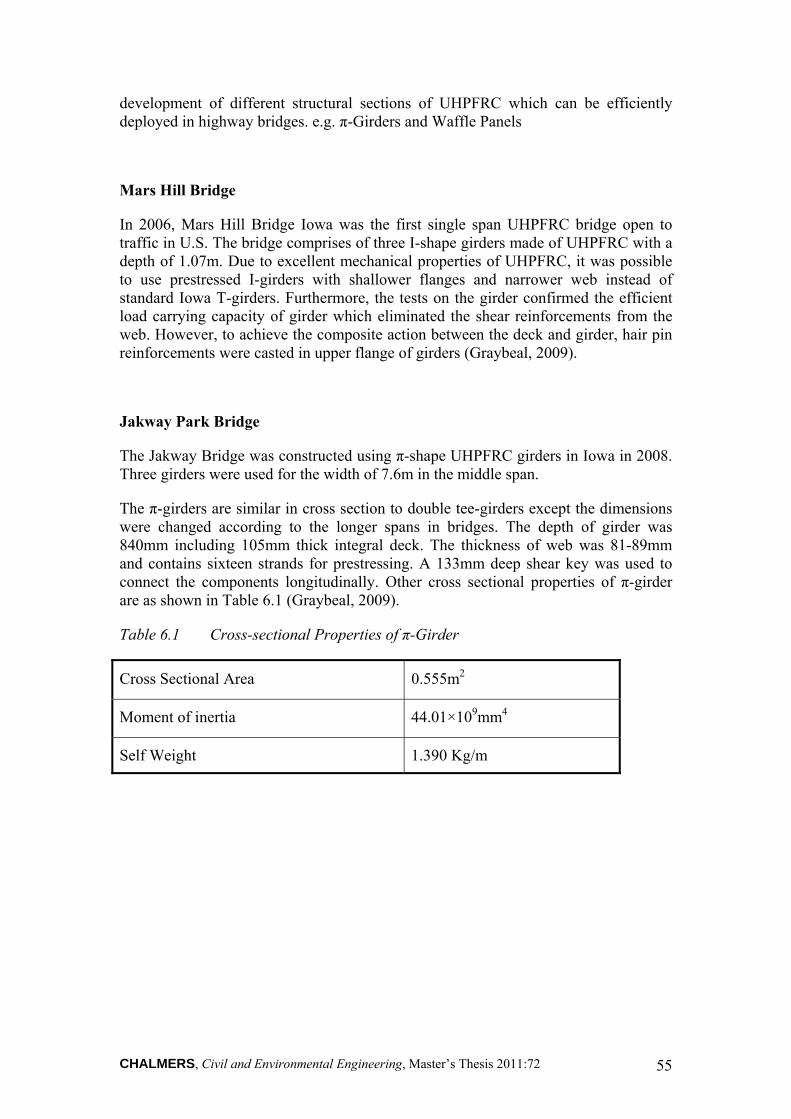
CHALMERS, Civil and Environmental Engineering, Master’s Thesis 2011:72 55
development of different structural sections of UHPFRC which can be efficiently deployed in highway bridges. e.g. π-Girders and Waffle Panels
Mars Hill Bridge
In 2006, Mars Hill Bridge Iowa was the first single span UHPFRC bridge open to traffic in U.S. The bridge comprises of three I-shape girders made of UHPFRC with a depth of 1.07m. Due to excellent mechanical properties of UHPFRC, it was possible to use prestressed I-girders with shallower flanges and narrower web instead of standard Iowa T-girders. Furthermore, the tests on the girder confirmed the efficient load carrying capacity of girder which eliminated the shear reinforcements from the web. However, to achieve the composite action between the deck and girder, hair pin reinforcements were casted in upper flange of girders (Graybeal, 2009).
Jakway Park Bridge
The Jakway Bridge was constructed using π-shape UHPFRC girders in Iowa in 2008. Three girders were used for the width of 7.6m in the middle span.
The π-girders are similar in cross section to double tee-girders except the dimensions were changed according to the longer spans in bridges. The depth of girder was 840mm including 105mm thick integral deck. The thickness of web was 81-89mm and contains sixteen strands for prestressing. A 133mm deep shear key was used to connect the components longitudinally. Other cross sectional properties of π-girder are as shown in Table 6.1 (Graybeal, 2009).
Table 6.1 Cross-sectional Properties of π-Girder
Cross Sectional Area 0.555m2
Moment of inertia 44.01×109mm4
Self Weight 1.390 Kg/m
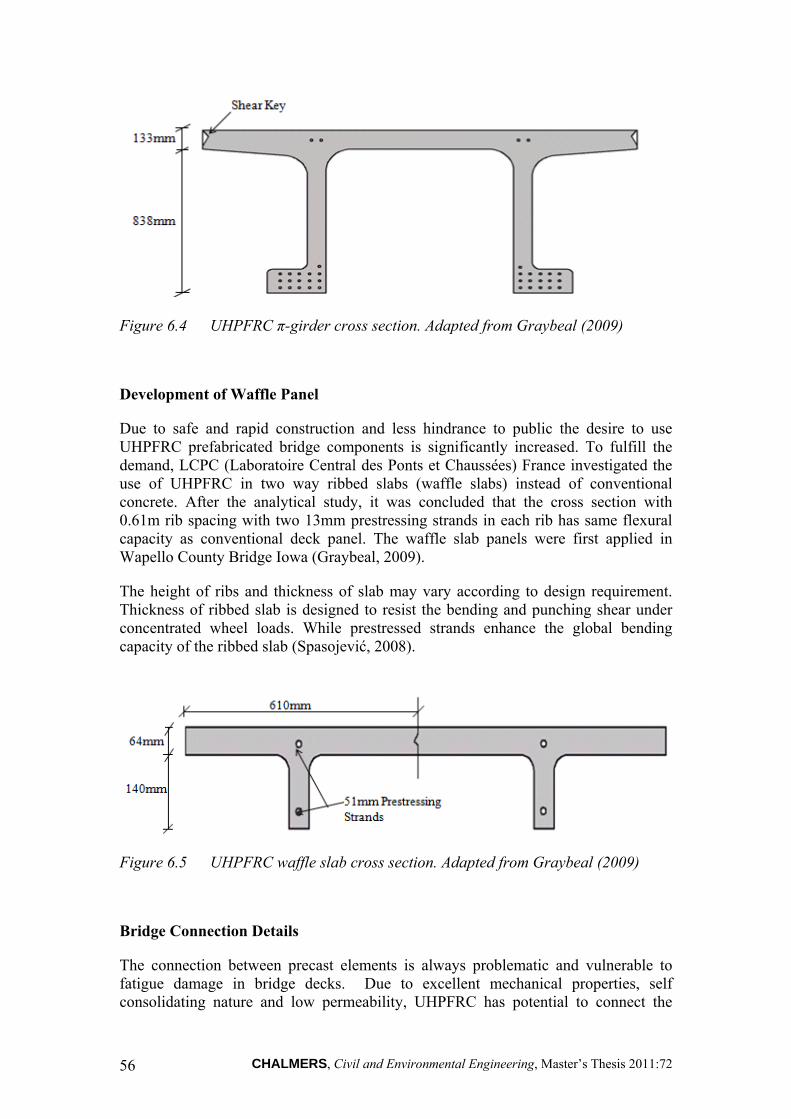
CHALMERS, Civil and Environmental Engineering, Master’s Thesis 2011:72 56
Figure 6.4 UHPFRC π-girder cross section. Adapted from Graybeal (2009)
Development of Waffle Panel
Due to safe and rapid construction and less hindrance to public the desire to use UHPFRC prefabricated bridge components is significantly increased. To fulfill the demand, LCPC (Laboratoire Central des Ponts et Chaussées) France investigated the use of UHPFRC in two way ribbed slabs (waffle slabs) instead of conventional concrete. After the analytical study, it was concluded that the cross section with 0.61m rib spacing with two 13mm prestressing strands in each rib has same flexural capacity as conventional deck panel. The waffle slab panels were first applied in Wapello County Bridge Iowa (Graybeal, 2009).
The height of ribs and thickness of slab may vary according to design requirement. Thickness of ribbed slab is designed to resist the bending and punching shear under concentrated wheel loads. While prestressed strands enhance the global bending capacity of the ribbed slab (Spasojević, 2008).
Figure 6.5 UHPFRC waffle slab cross section. Adapted from Graybeal (2009)
Bridge Connection Details
The connection between precast elements is always problematic and vulnerable to fatigue damage in bridge decks. Due to excellent mechanical properties, self consolidating nature and low permeability, UHPFRC has potential to connect the

CHALMERS, Civil and Environmental Engineering, Master’s Thesis 2011:72 57
conventional precast elements. The six precast decks with UHPFRC as binding material were tested under cyclic loading. The results showed the optimal use of UHPFRC as a durable binding material in deck connections (Graybeal, 2009).
6.2.6 Shepherds Creek Road Bridge, NSW, Australia
In 2004, first application of UHPFRC of Ductal® family for highway traffic was completed in Australia. A single span timber bridge was replaced by concrete bridge. The bridge supports 4 lanes and 15m in length. The UHPFRC used in the bridge was fabricated in Australia with compressive strength of 200 MPa, flexural strength of 45 MPa and young’s modulus of 47 GPa.
The superstructure of the bridge was constructed with precast Ductal® beams. The slab of the bridge was casted on Ductal® panels formwork between the beams which provide extra safety to bottom surface of slab. The weight of UHPFRC beams decreased to half of the weight of beams with conventional concrete. After completion of two lanes load tests on the bridge confirmed the design. Consequently in 2005, RTA (road Traffic Authority) proved the Ductal® to be used for roads and bridges in Australia (Rebentrost & Wight, 2008).
6.2.7 Papatoetoe Footbridge, New Zealand
The first Ductal® foot bridge constructed in New Zealand is 175m long, with 10 simply supported spans. Beams were fabricated in Australia in Ductal® plant. The beams have holes in the web and consist of 50mm thick slab. The deck slab is 2.2m wide and casted without conventional reinforcement. Ductal® due to its high compressive and tensile strength supports the deck slab. Furthermore, the Ductal® beams were significantly lighter than the beams with conventional concrete. The ribs spaced at 2.7m centre to centre. The strands were provided for post-tensioning under each rib and slab. The beams with Ductal® provide durable and lightweight engineering solution (Rebentrost & Wight, 2008).
6.2.8 Sakata-Mirai Foot bridge, Japan
The Sakata-Mirai Bridge is the first application of Ductal® in Japan. The deck slab was designed without passive reinforcement. The necessary strength was provided by Ductal® and external prestressing. The bridge is a single span and 50.2m in length. The bridge is cambered from the centre to satisfy the deflection criteria. The finite element analysis of bridge verified the design of the bridge. Two highway bridges were also constructed with Ductal® in 2005 and 2006 respectively (Rebentrost & Wight, 2008).

CHALMERS, Civil and Environmental Engineering, Master’s Thesis 2011:72 58
6.3 Life cycle cost analysis of UHPFRC bridge
In 2006, a single span highway bridge (Mars Hill Bridge) was constructed with the use of Ductal® as construction material in Wapello County, IOWA, USA. This bridge has been constructed of UHPFRC girders and cast-in-situ NSC deck and substructure (Ahlborn et al, 2008).
Here a case study has been done on two types of bridges to calculate the LCC of these bridges. First bridge is constructed of NSC girders, deck and abutments. Second bridge is constructed of UHPFRC girders and deck but NSC abutments (Ahlborn et al, 2008).
The NSC Bridge is single span with a total length of 33 meters and can accommodate two lanes of traffic. The NSC cast-in-situ deck is 7.5 meters wide and 0.23 meters thick. Three NSC precast prestressed I-beams are used as girders to support the deck. The design life of this bridge is 90 years (Ahlborn et al, 2008).
The UHPFRC Bridge is also a single span with total length of 33 meters and can accommodate two lanes of traffic. The UHPFRC precast deck is 7.5 meters wide and 0.10 meters thick. Three UHPFRC prestressed T-beams are used as girders to support the deck. The design life of this bridge is 180 years (Ahlborn et al, 2008).
The LCC analysis has been done in 2005-2006, according to RS Means Data and cross checked according to Michigan Engineers’ Resource library (MERL). An inflation rate of 3% per year should be kept in mind for future calculations. For reference, the estimated cost of Mars Hill Bridge has been used which is $432,000 /-. Table XX shows the comparison of the LCC cost of NSC Bridge and UHPFRC Bridge (Ahlborn et al, 2008).
Table 5.6 Comparison of the LCC Analysis of NSC Bridge and UHPFRC Bridge Adapted from Ahlborn et al. (2008).
Activity NSC Bridge UHPFRC Bridge
Construction $273,000 /- $497,000 /-
Maintenance $71,000 /- $4,000 /-
Total $344,000 /- $501,000 /-
It can be seen from the Table 5.6 that NSC Bridge cost $344,000 /- per 90years, while UHPFRC Bridge cost $501,000 /- per 180 years. Apparently, NSC Bridge is still cheaper than UHPFRC Bridge for a life span of 180 years. The cost of NSC Bridge is $130 per cubic meter and that of UHPFRC Bridge is $2615 per cubic meter. It can be clearly seen that the cost of UHPFRC Bridge is 20 times greater than NSC Bridge. However, the traffic disturbance cost has not been included for yearly maintenance of NSC Bridge, and deck replacement time and traffic disturbance cost has also not been included in NSC Bridge. In addition, if the efficient cross section of UHPFRC Bridge is used and incorporate user cost and special benefits of UHPFRC is added in

CHALMERS, Civil and Environmental Engineering, Master’s Thesis 2011:72 59
calculation then the UHPFRC Bridge cost can be reduced to 12.5 % per cubic meter (Ahlborn et al, 2008).

CHALMERS, Civil and Environmental Engineering, Master’s Thesis 2011:72 60
7 Case study- The Källösund Bridge
This section treats the bridge where damage has been found in the edge beams. The formation of cracks has been found in the edge beams. Moreover, the corrosion of reinforcements in the edge beams has also been observed. This lead to the spalling of concrete from edge beams. Investigations and test have been carried out to check the performance of the edge beams. It was found that the edge beams are failed to perform according to the design load and needs to be replaced.
A case study is done in this section to study the rehabilitation of the Källösund Bridge done in past years. Furthermore, a new solution for the rehabilitation of the Källösund Bridge by application of UHPFRC is also proposed.
7.1 Description of the bridge
The Källösund Bridge was constructed in 1958-1959 to connect the two islands Tjorn and Orust to the mainland near the west coast of Sweden. It is a prestressed, box-girder bridge constructed by the free cantilevering method. The total length of the bridge is 325 m divided in four spans have length of 50 m, 107 m, 107 m, and 50 m respectively. The bridge was constructed with cast in-situ concrete (Samuelsson, 2005).
Figure 7.1 The Källösund Bridge seen from Stenungsöns, west direction. (Plos et al ,2004)
The free width for the traffic is about 7.5 m with a slope of 2.5 %. The bridge deck slab is 7.5 m wide with a thickness of 200 mm. The bridge deck is about 34 m above

CHALMERS, Civil and Environmental Engineering, Master’s Thesis 2011:72 61
the sea level and the bridge girder is supported by three piers and two abutments. The main box girders of the bridge were constructed in parts as free balancing cantilevers. The girders were then connected with each other by hinges. The height of the girders varies from 7.5 m at the piers to 1.6 m at the abutments. A cross section of the box girder is shown in Figure 7.2. The thickness of the bottom slab of the girder varies from 260 mm to 200 mm. The girder wall thickness is 450 mm (Samuelsson, 2005).
Figure 7.2 Cross Section of box-girder the Källösund Bridge. Adapted from Puurula (2004)
It was prestressed in both longitudinal and transversal direction with reinforcement of 26 mm in diameter. The main reinforcement in the bridge girders is prestressed. Most of the prestressing reinforcement was placed in the bridge deck slab, i.e. the top flange of the cantilevering bridge girders. The non prestressed reinforcements consist mainly of deformed bars of 10 mm diameter and of quality Ks40, i.e. ductile steel with characteristics yield strength slightly above 400 MPa (Samuelsson, 2005).
The concrete quality in the bridge girders corresponds to high quality bridge concrete of the time of construction with a characteristics compressive strength of approximately 40 MPa. The material and mechanical properties of the concrete were tested by the Swedish Road Administration in connection with the structural assessment and rehabilitation of the bridge (Samuelsson, 2005).
In 1982, a 2.5 m wide pedestrians and bicycle path (GC-path) was constructed along the southern side of the bridge. The GC-path was constructed of steel and was connected to the bridge girders using steel trusses (Samuelsson, 2005).
7.2 Damage detection and replacement of the edge beams
The expansion joints of the bridge have been rehabilitated twice, in 1982 and in 1993. The major problem observed was the 10 mm movement of the joints due to spalling out of concrete and cracks formation. Due to this large gap in the joints the chloride water passed in the deck slab and damaged the underside of the slab. In 1980’s the

CHALMERS, Civil and Environmental Engineering, Master’s Thesis 2011:72 62
splitting out of concrete cover was observed from the undersides of the edge beams. During the inspection in 1990 it was found that the entire northern part of the edge beams is damaged and also some parts in the southern side are damaged. In 2002, thorough observations showed that both the edge beams are damaged along its entire length. In 2003 and 2004, the damaged edge beams have been replaced by new one (Samuelsson, 2005).
Here the process of the replacement of the eastern part of the southern edge beam has been presented. The damaged edge beam was removed in a systematic way. A high pressure water blower was used to remove the damaged edge beam so that the transversal reinforcement can be preserved. Then the part of the deck slab adjacent to edge beam was cleaned off, of the loose concrete particles and was watered. The damaged edge beam was replaced with a new one. The casting of concrete was done in successive segments of 8 m length. The concept of segmental casting was adopted, to accommodate any elongation during hardening of fresh concrete. Strain gauges were installed in the edge beams at different positions to measure any elongation occurred. The casting was initiated from the middle of the end span towards the Stenungsöns abutment. An 8 meter segment was cast in week 41 followed by another 8 m segment in week 42. In week 43 the remaining part was casted. The edge beam casting was done in two different cooling conditions to observe the effect of temperature. First the non cooling casting was done followed by the cooling casting. A cooling pipe was used in the casting of edge beam to reduce the risk of temperature cracks. The temperature of the cooling water inside the pipe was maintained between 8 to 15°C. The type of concrete used was C35/45 with water cement ratio of 0.4 (Samuelsson, 2005).
While the concrete was getting hard, the temperature development was noted down at different sections after an interval of 10 minutes, both for the cooled casted part and non cooled casted part. ConReg 706 was used as data logger for middle sections and SwemaLogg 15 was used for edge sections and the sections between cold water and deck slab (Samuelsson, 2005).
The deformation was recorded at different sections by using the strain gauges. The total deformation recorded is the sum of temperature deformation, stress induced strain and shrinkage (Samuelsson, 2005).
The restraint stresses produced in the cooling part were 1.21 MPa and 2.11 MPa in the non cooling part. This clearly shows that the cooling has positive effect in the hardening process and reduces the risk of cracks. However, after three months, cracks were observed in the parts of the edge beam (Samuelsson, 2005).
7.3 Rehabilitation alternative with UHPFRC
Only after 3 months cracks were observed in parts of the edge beam again. Therefore, an alternative solution is presented here focussing on the potentials of UHPFRC.
The recipe of UHPFRC use for rehabilitation should full fill following goals. The UHPFRC mix should have very low permeability to fluids and gases and shouldn’t show macro cracking. The mix should show excellent mechanical performance and

CHALMERS, Civil and Environmental Engineering, Master’s Thesis 2011:72 63
self compacting character. Denarié (2009), project has provided some guidelines in selection of UHPFRC recipe for the rehabilitation purpose. The UHPFRC prefabricated elements with 2% fibers volume are sufficient to be use in the case where there is less hindrance to early age shrinkage and bending behaviour is dominant. In case of cast on site as UHPFRC overlays, where existing structure restraint the early age shrinkage of new matrix. Consequently, the tensile stresses produce in the matrix. To accommodate these stresses the matrix must exhibit tensile hardening response for which high dosage of fibers up to 6-9% by volume will be sufficient (Denarié, 2009).
Due to the above mentioned mechanical and long term durable properties of UHPFRC, the edge beams will be constructed by UHPFRC. Furthermore, overlay of UHPFRC will be provided over the whole width of bridge deck.
7.3.1 Composition of UHPFRC
During the ARCHES project two new recipes of CEMTECmultiscale® with new matrices
with different rheological properties were developed in Slovenia. The basic properties of the both recipes were same as CM23 recipe used in the rehabilitation of La Morge Bridge in 2004. However, limestone filler reduced the amount of cement from the 1434 kg/m3 to 763 kg/m3. Their water/ (cement + limestone) was 0.170. The component details of both recipes are shown in Table 7.2.
Table 7.2 Composition of CEMTECmultiscale® recipes (Denarié et al., 2009)
Components CM32_11 CM32_13
Cement 763 kg/m3 763 kg/m3
Limestone (filler) 763 kg/m3 763 kg/m3
Micro Fibers L =1 mm L =1 mm
Macro fibers Lf =10 mm Lf =10 mm
Slope tolerance Limited High
The CM32_13 recipe was designed with addition of a thixotropizing agent SIKA Extender®, as result it can tolerate slope up to 5%. These recipes were prepared and applied for the first time in 2009, for the rehabilitation of LOG ČEZOŠKI Bridge Slovenia. The mixing time for materials was 12 minutes and no segregation was reported. Further test on workability over 2 hours intervals showed no significant loss of slump (Denarié, 2009).

CHALMERS, Civil and Environmental Engineering, Master’s Thesis 2011:72 64
7.3.2 Application of UHPFRC
UHPFRC is a relatively expensive material and it should be applied to structures subjected to severe environmental conditions and where more resistance is required without increasing the dead load of the structure. The less exposed and loaded parts of the structure are built of NSC.
The surface of the existing concrete is made rough with hydro-jetting before the application of the UHPFRC to ensure good bonding between the two layers. The cross section of the bridge after rehabilitation is shown in Figure 7.3 and Figure 7.4. The edge beams and overlay of the deck slab will be monolithically cast on site with UHPFRC. There is no slope tolerance required for edge beam so it will be casted by recipe CM32_11. However, slope is required for water drainage over the bridge deck. Therefore overlay will be casted with recipe CM32_13.
Figure 7.3 Proposed Cross Section of Edge beam and overlay casted with UHPFRC
Figure 7.4 Cross section of Bridge after Rehabilitation with UHPFRC
A significant traffic passes over the bridge every day. Therefore, UHPFRC will be casted in two steps on almost 10 m wide deck. In first step overlay will be casted over one lane will be continuously moist cured. When the overlay will get enough strength, this lane will be open to traffic. Similarly in second step other lane will be casted with

CHALMERS, Civil and Environmental Engineering, Master’s Thesis 2011:72 65
UHPFRC overlay. The overlay will be casted continuously to expansion joints in such a way to avoid transverse dry joints. However, longitudinal joints between two layers will be specially designed to transfer the tensile forces between two layers. Typical longitudinal joint between UHPFRC layers was first applied during ARCHES project for the rehabilitation of Log Čezsoški bridge Slovenia as shown in Figure 7.5.
Figure 7.5 Details of Longitudinal joint between UHPFRC layers. Adapted from Denarié et al. (2009)
7.3.1 Environmental impact
Every human being needs comfort, satisfaction and happiness. Since the very beginning of human kind, struggles have been done to achieve these basic needs of life. With the passage of time research and development has been done to get more and more products from the available resources. Enormous development has been done till now, as a result the world is becoming more and more industrial and chemical instead of natural. It is very important for the world, to develop and become more and more prosperous.
However, the development has lead to certain reversible and irreversible problems in the nature such as CO2 emissions, population increase, agriculture decrease, and chemical increase, and ozone layer disturbance, landscape degradation, forestry decrease, acid rains, and wastage of energy, inefficient use of energy etc. Therefore, efforts should be made to stop this disturbance of the natural system. However, it is not logical to stop the development of human being. Alternatively, struggle has to be made to effectively use this development for the betterment of human kind. Energy should be used to assure the need of human kind and also to save energy for future. Chemical industry should progress more and more keeping in view the natural safety and preservations. Therefore environmental problems should be addressed with systematic approach. Furthermore a sustainable development pathway should be adopted (Denarié et al, 2005).
The building materials sector is one of the largest CO2 emission sectors, of which concrete structures contribute the largest share. Due to industrialization an enormous

CHALMERS, Civil and Environmental Engineering, Master’s Thesis 2011:72 66
amount of available natural resources are used for development. In the past few decades the demand of natural resources has been significantly increased. The environmental disorder is one of the key problems that the world is facing for the last few decades. People from every scope of life are trying to address this serious issue within their own capacity (Denarié et al, 2005).
Due to this ideology of rehabilitation system, which consumes fewer materials and emits less CO2 have to be developed. The sustainability study during ARCHES project based on CO2 calculation showed that application of UHPFRC with 50% limestone filler is most sustainable rehabilitation system as compared to other standard system for rehabilitation. Past experiences of rehabilitation of bridges with UHPFRC showed the fewer disturbances to the traffic than the standard rehabilitation systems (Denarié et al, 2005).
7.4 Comparison of the two alternatives
The average daily traffic on Källösund Bridge is 15500 vehicles (ADT). It is a very expensive job to rehabilitate the bridge after a short time. The Swedish Road Administration spends a huge amount of money on rehabilitation of bridges every year. Therefore, the bridge is rehabilitated with UHPFRC in the proposed solution.
Ultra High Performance Fiber Reinforced Concrete (UHPFRC) is characterized by a unique combination of extremely low permeability, high strength and deformation capacity. During the SAMARIS project UHPFRC have been applied for the rehabilitation of bridges. The application of UHPFRC on bridges has demonstrated that it gives a good solution for cast in-situ rehabilitation by using standard equipment. The hardening of UHPFRC requires less time than NSC thus the traffic disturbance time can be reduced to a considerable level. Due to fast and efficient rehabilitation by using UHPFRC the Life Cycle Cost can be reduced further. Furthermore, no waterproofing membrane is needed when using UHPFRC. Thus, the bituminous concrete can be applied after only 8 days of moist curing of the UHPFRC instead of the usual 3 weeks of moist curing of NSC. Due to high abrasion resistance of UHPFRC, it is proposed that it can be used without bituminous concrete even. The sustainability study during ARCHES project based on CO2 calculation showed that application of UHPFRC with 50% limestone filler is most sustainable rehabilitation system as compared to other standard system for rehabilitation. Also, the durability of UHPFRC is much higher than usual concretes (Weirzbicki, 2010).

CHALMERS, Civil and Environmental Engineering, Master’s Thesis 2011:72 67
8 Case Study: Bridge over Tolångaån
Composite bridges have become a reliable and popular solution in many countries. Steel girders are provided to support a concrete deck slab. The deck slab is connected to the steel girders by shear connectors or headed studs. For more details on joints between steel girders and prefabricated slab elements see Collin et al. (2002).
One of the advantages of composite bridge construction is that steel beam can carry the weight of the wet concrete during casting; therefore no extra temporary structure is required. Also the construction time for the bridge reduces, which may save money particularly during winter time in cold countries. Moreover, casting of bridge deck slabs with prefabricated elements is an even faster way of construction. But one of the main problems in prefabricated elements is how to cast the joint between prefabricated elements as joints are normally the weakest part in the construction (Collin et al. 2002).
In Sweden, the bridges have mostly cast-in-situ bridge deck slabs using normal strength concrete as construction material.
8.1 Description of the bridge
Here a case study has been presented of a bridge located in Sweden. The bro M 1255 Tolångaån is located in Sjöbo, Skåne, Sweden. The longitudinal structural system is a bridge deck supported on both sides by two abutments. The supports are hinge supports which allow horizontal movement. A bridge deck slab supported on two girders is the main structural system. The slab is cast-in-situ NSC with two steel girders. The total length of the bridge is 30.80 meters. The total width of the deck is 8 meters (Trafikverket, 2000).
The load case used is according to BRO 94 PUBL. 1994:2 as shown in the Figure 8.1 below (Trafikverket, 2000).
Figure 8.1 Load case BRO 94 PUBL. 1994:2. Adapted from (Trafikverket, 2000).

CHALMERS, Civil and Environmental Engineering, Master’s Thesis 2011:72 68
The deck slab is spanned transversely between two girders and cantilever transversely at the outer sides of the girders. The deck slab is 6.5 meters wide having a gradient of 2.5%. The deck slab is 310 mm thick at the centre and 210 mm thick at the edges near the edge beams. The K45 strength class concrete is used for the construction of cast-in-situ bridge deck slab. Water cement ratio used is 0.45. The type of reinforcement used is Ks60. The concrete cover used is 100 mm (Trafikverket, 2000).
Normal strength concrete is C30/37 with fck 30 MPa, fctm 2.9 MPa and Ecm 32 GPa
Height of the girder is 1065 mm with upper flange smaller than the lower flange. Composite action is achieved between the slab and the girders by using two connectors at the top flange of the girder. The two girders used to distribute the traffic load are spaced 4 m. It also transfers the vertical load from the traffic to the abutments (Trafikverket, 2000).
Figure 8.2 Bridge deck slab cross section constructed with NSC. Adapted from (Trafikverket, 2000).
Edge beams having 400×420 mm dimension are provided at the edges of the deck slab. The K40 strength class concrete is used as construction material for edge beams. The reinforcement used is Ks60 (Trafikverket, 2000).
Figure 8.3 Edge beam detailing. Adapted from (Trafikverket, 2000).

CHALMERS, Civil and Environmental Engineering, Master’s Thesis 2011:72 69
8.2 Bridge alternative with prefabricated bridge deck slabs and UHPFRC
In this section application of UHPFRC for construction of a bridge deck slab of composite bridge is proposed. The bridge deck slab is constructed with precast normal strength concrete elements.
8.2.1 Description of the bridge
Here application of UHPFRC for the construction of a new bridge is presented. The bridge description is same as explained in section 8.1 but bridge deck slab is considered as precast in this case.
The bridge deck slab is supported over steel beams. The cross section and connection of these beams with prefabricated deck slab will be chosen according to the design requirements in Eurocode. The bridge deck slab and edge beams are constructed with precast normal strength concrete. Precast elements of slab are connected together by UHPFRC joints. An overlay of UHPFRC is laid over the whole bridge including edge beam see Figure 8.4. The properties of NSC and reinforcement for the pre-cast slab will be selected according to the design specifications of the bridge. In case of cast in situ overlay, early age shrinkage of UHPFRC layer will be restrained which will develop tensile stresses in the new overlay. To overcome these stresses and obtain the delayed micro cracking even ultimate strength of matrix is reached, the UHPFRC must exhibit strain hardening. (For more details on restrain stresses read Habel, 2008). For this, UHPFRC needs less dispersion of mechanical properties due to fibrous mix. Many UHPFRC recipes are under development in the world. Very few recipes can satisfy at same time low permeability, strain hardening, high tensile and compression stress and self compacting behavior. The recipes developed using lime filler as replacement of unhydrated cement were found more suitable recipes which improved workability without compromising the strength of the matrix. In addition the slope tolerance of specific recipes was enhanced for cast in-situ application with slopes 3 to 5%. These recipes are CM32_11 and CM32_13. The composition of these recipes is given in Table 7.2. Moreover, the recipes can be made very easily worldwide (Denarié et al., 2009). The bituminous concrete layer will be used over the UHPFRC layer to provide slope of 2.5% to both sides from centre for the drainage of water.

CHALMERS, Civil and Environmental Engineering, Master’s Thesis 2011:72 70
Figure 8.4 Proposed cross section of the composite bridge deck with NSC prefabricated Slab and UHPFRC Overlay
8.2.2 Joints Details
Joints are used as to connect two pieces of concrete together and to transfer the forces acting on them. Generally joints can be classified into two types. In first type, the joints can transfer the moments. While, in 2nd type joints cannot transfer the moments. Joints of first type develop a continuous structure with adjacent prefabricated elements. Therefore these types of joints are more preferred.
Since structural behavior of prefabricated elements is mainly govern by the joints between them. Therefore, detailing of these joints is one of the main issues to provide best performance in regard to efficiency. Prefabricated decks slabs are usually precasted with the same length as width of the bridge deck and their width is usually less than 2 m (Harryson, 2008). Consequently, with conventional joints it becomes more complicated as they involve loop bars and more transverse reinforcements as show in the Figure 8.5 (a). However, there is still need for new joints which are easy and fast to perform, and which makes the surrounding prefabricated elements continuous Model code 1990 provides some guidelines about easy and quick installation of the joints between prefabricated elements. (Harryson, 2008)
In 2008, Peter Harryson presented idea of casting of joints between prefabricated elements with UHPFRC. The aim of his work was to design a joint which is easy to install and perform better. Therefore, new joint 100 mm wide, with simple reinforcement detail was casted with CRC having water/binder ratio of about 0.16. Furthermore, these joints were tested for fatigue, shear and bending capacity in Chalmers University of Technology. The results showed that the joints become much stronger than the connecting parts if proper detailing of lap length is provided which was almost equal to 80mm. Moreover, the transverse reinforcement enhances the

CHALMERS, Civil and Environmental Engineering, Master’s Thesis 2011:72 71
ductile behavior of the joint. For more details on tests on connection between prefabricated slabs casted with UHPFRC see (Harryson, 2008)
In this case, prefabricated joints are casted with CM32_11 as there is no slope requirement. The mechanical and durability properties of CM32_11 are almost similar to CRC except the composition of recipes. Despite this CM32_11 has significant tensile capacity to resist the retraining forces. Also it can be easily prepare in all over the world. The splice length of the reinforcement is equal to the width of the joint i.e. 100 mm as shown in Figure 8.5 (b).
(a)
(b)
Figure 8.5 Joint between Prefabricated Slab casted with (a) Normal strength concrete (b) UHPFRC. Adapted from Harryson (2008).
8.2.3 Application of UHPFRC overlay
After casting the connections between prefabricated deck slabs, a continuous 2.5 cm UHPFRC overlay of recipe CM32_13 with no dry joint is applied over upper face of bridge deck and edge beam. Despite this, sides of the edge beam are casted with recipe CM32_11 as no slope tolerance required. Formwork is used for casting of these layers of edge beam. However, formwork has to remain open from lower side to

CHALMERS, Civil and Environmental Engineering, Master’s Thesis 2011:72 72
guarantee the continuity of the overlay over edge beam and upper face of deck without any dry joint as shown in figure 8.4. The stiffness of the composite slab is significantly improved by the application of 2.5 cm thick UHPFRC layer.
8.2.4 Comparison of bridge deck alternatives
A case study was done to study the comparisons between the bridge deck slab constructed on site with normal strength and prefabricated slab with UHPFRC joints and overlay.
In first case bridge deck slab is casted on site with normal strength concrete and supported by steel girders. Structures built with normal strength concrete performs very well in most applications but still lacks durability under severe environmental conditions.
In second case the bridge deck slab was constructed with precast elements and the study on joints casted with UHPFRC revealed that joints can be made stronger than the surrounding prefabricated elements by proper detailing and providing sufficient lap length for reinforcement. An overlay of 2.5 cm thick of UHPFRC is casted for protection purpose over the bridge deck slab according to the design configuration presented by Habel, 2004. The overlay acts as water tight membrane and resists the penetration of salts into concrete and makes the slab more stiff, thus increases the service life of the bridge deck. But life cycle cost in this case will be higher than the cast in-situ bridge deck slab as shown in section 6.4. However, the duration of the construction works and closing of traffic lanes could be largely reduced.

CHALMERS, Civil and Environmental Engineering, Master’s Thesis 2011:72 73
9 Conclusions
In this thesis a study was done to investigate the problems related to bridge deck slabs. Bridge decks are constantly subjected to traffic loads and are exposed to environmental actions. Consequently they deteriorate faster than the other parts of the bridge. The use of de-icing salts leads to chloride penetration and corrosion of steel reinforcement.
The major maintenance problem for concrete bridges is corrosion of reinforcement. The corrosion of reinforcement can be controlled by improved protection of the reinforcement through cathodic protection, protective reinforcement coating or non corrosive reinforcement material. An alternative is to have an impermeable and uncracked concrete cover. One way to obtained this is by using Ultra High Performance Fiber Reinforced Concrete (UHPFRC).
UHPFRC has shown high very high compressive strength (more than 160 MPa) and large tensile strength (more than 8 MPa), along with strain hardening behaviour which ensures the formation of multiple micro-cracks and keeps the crack width small. However, fiber orientation and casting techniques significantly affects the mechanical properties of UHPFRC. The UHPFRC has been found to be more resistant to chloride attack, freeze-thaw attack, alkali aggregate attack and abrasion in durability studies conducted by various researchers. Strain hardening is an essential property of UHPFRC since it keeps it less permeable even after crack initiation. Therefore, an overlay of UHPFRC shows better resistance against aggressive environmental effects and increases the service life of bridge deck slabs.
Successful rehabilitation of bridge deck slabs is a major issue. When a new layer of UHPFRC is applied over the existing concrete structure, a new composite structure is formed. Eigen stresses are produced in the new layer due to restrained shrinkage. Due to both deformability and strain hardening behaviour, the intensity of induced stresses is reduced.
UHPFRC has been applied to several bridges, both for rehabilitation and construction of new bridges. A sustainability study during the ARCHES project based on CO2
calculation showed that application of UHPFRC with 50% limestone filler was the most sustainable rehabilitation system compared to other standard system for rehabilitation.
The effect of using UHPFRC was studied in two case studies, in which the rehabilitation of an old bridge and the construction of a new bridge were compared to UHPFRC alternatives. The concept of application of UHPFRC was to use it where the structure is more exposed to severe environment actions and high traffic loads. This conceptual idea significantly improves the durability and decreases life cycle costs of both rehabilitated and new concrete structure.
Application of UHPFRC also reduces the layer thickness in case of rehabilitation and increases the capacity of structure without increasing deadweight.
UHPFRC also reduces the duration of rehabilitation works; traffic lanes can be open after few days. In addition, if the efficient cross section of UHPFRC bridge is taken

CHALMERS, Civil and Environmental Engineering, Master’s Thesis 2011:72 74
into account and the user cost and special benefits of UHPFRC is added in the calculation, the bridge deck cost can be reduced by approximately 10 %.
The application of UHPFRC in the composite bridge construction with prefabricated elements enhance the service life of the bridge deck slab by providing stronger joints between the prefabricated bridge deck elements and by applying a non-permeable UHPFRC overlay on the bridge deck slab.
A major advantage of prefabricated construction is shorter construction time. Prefabricated concrete members have potential to be more durable than the cast in-situ concrete if they are made in controlled construction environment in factory. However initially more investment is required for plant machinery in case of prefabrication of concrete, but this investment is often economical over time.

CHALMERS, Civil and Environmental Engineering, Master’s Thesis 2011:72 75
10 Further Studies
Deterioration of bridge deck slabs is a widely used subject for research since many decades. A large amount of investigations have been found in literature throughout the world. In this thesis an effort has been done using UHPFRC, to improve the performance of bridge deck slabs with respect to severe environmental conditions and traffic load. However, UHPFRC being relatively a new construction material requires further studies to be used as construction material for rehabilitation of bridges as well as for construction of new bridges. Application of UHPFRC to bridge deck slabs should be studied through laboratory tests as well as on-site tests to ensure the reliability. Here are a few suggestions for further studies;
Structural behaviour of composite action of UHPFRC and NSC.
Structural response of UHPFRC with conventional reinforcement.
Detail research is needed to develop more efficient cross sections of bridge decks using UHPFRC.
Detail Design Guidelines of fracture mechanics of UHPFRC needed to develop.
Fatigue properties need to be further investigated.
Research should be expanded in the areas of design optimization of manufacturing. In particular, faster and more economically efficient production methods need to be investigated. Also, by developing a design approach that expects a longer service life and less maintenance costs.

CHALMERS, Civil and Environmental Engineering, Master’s Thesis 2011:72 76
11 References
AASHTO (2010): AASHTO LRFD Bridge Design Specifications, Customary U.S. Units, 5th Edition, with 2010 Interim Revisions, Washington, DC
Ahlborn, T.M., Peuse, E.J., Misson, D.L. (2008): Ultra-High-Performance-Concrete for Michigan Bridges Material Performance – Phase I. Research Report RC-1525, Michigan Department of Transportation Construction and Technology Division, PO Box 30049, Lansing MI 48909, USA, (2008), pp 181.
American Concrete Institute (2005): Building code Requirements for Structural Concrete (ACI 318-05) and commentary (ACI 318R-05), American Concrete Institute, USA.
Benmokrane, B., El-Salakawy, E., El-Ragaby, A., (2004): Design Construction and Monitoring of Four Innovative Concrete Bridge Decks Using Non-Corrosive FRP Composite Bars, Department of Civil Engineering, University of Sherbrooke, Quebec Canada.
Boverket, (1994): Boverkets handbok om betongkonstruktioner BBK 94, Band 1, Konstruktion (Boverket´s handbook on Concrete Structures BBK 94, Vol. 1 Design, In Swedish), Boverket Byggavdelningen Karlskrona, Sweden, 185 pp.
Bornemann, R., Schmidt, M., (2002): The Role of Powders in Concrete, proceedings of 6th International Symposium on Utilization of High Strength/ High Performance Concrete, Leipzig, Vol 2, pp. 863-872.
Bone David, (2004): Corrosion Inhibitors, current practice sheet no.6, Royal Haskoning, Concrete Bridge Development Group, UK
Brown, M., Sellers, G., Folliard, K.J., Fowler, D.W., (2001): Restrained Shrinkage Cracking of Concrete Bridge Decks: State of The Art Review. Research Project 0-4098. Centre for Transportation Research, the University of Texas, Austin
Broomfield, John P., (1997): Corrosion of Steel in Concrete Understanding, investigation and repair, eBook ISBN: 978-0-203-47528-7, Spon Press, Chapter 3.
Buzzine, D., Dazio, A., Trub, M., (2006): Quasi-static Cycle Tests on Three Hybrid Fiber Concrete Structure Walls, Die Dutsche Bibliothek, ETH, Zurich, Switzerland.
Carino, N. J., Meeks, K. W., (1999): Curing of the High Performance Concrete-Report of the state-the-art, Building and Fire Research Laboratory, National Institute of Standards and Technology Gaithersburg MD 20899, USA
CEN (2004): Eurocode 2, Part 2, Bridges, European Committee for Standardization, Brussels.

CHALMERS, Civil and Environmental Engineering, Master’s Thesis 2011:72 77
Charron, J.P., Denarie, E., Bruhwiler, E. (2006): Permeability of ultra high performance fiber reinforced concrete (UHPFRC) under high stresses, Material and Structures, Vol. 1 / 1968 – Vol. 44 / 2011, pp.269-277.
Chen, Wai-Fah., Duan L., (2000): Bridge Engineering Handbook. CRC Press LLC, Boca Raton, Florida.
Clemeñ, G. G., Jackson D. R., (2000): Cathodic Protection of Conctere Bridge Decks Using Titanium-Mesh Anodes. Research report VTRC 00-R14, Virginia Transportation Research Council, Virginia USA.
Collin, P., Stoltz A., Moller M., (2002): Innovative Prefabricated Composite Bridges, IABSE Symposium Melbourne, 2002.
Collin, P., Veljkovic, M., Pétursson, H. (2006): International Workshop on the Bridges with Integral Abutments, Topics of relevance for the INTAB project. Luleå University of Technology, Luleå, Sweden. Pp. 77.
Coughlin, T. (2004), Steel Free Deck Slab construction in Bridges, CE 247 Concrete technology, University of Berkeley USA
Crocetti, R. (2001): On some Fatigue Problems Related to Steel Bridges. Ph.D. Thesis. Department of Structural Engineering, Chalmers University of Technology, Publication no. 01:2, Göteborg, Sweden, 2001, 152 pp.
CRC Technology Apps, Denmark (2011), Available at http://www.crc-tech.com/Mechanical-properties-207.aspx (2011-03-24).
DENSIT®, Aalborg, Denmark (2011), Available at http://www.densit.com/ (2011-04-11).
Denarié, E., (2005): Full Scale Application of UHPFRC for the Rehabilitation of Bridges-from lab to the field, SAMARIS report, No. Sam_GE_DE22v03_01. {December} 2005, Ver. Final, pp. 63.
Denarié, E., (2009): Recommendations for the tailoring of UHPFRC recipes for rehabilitation, ARCHES Project, Report No. ARCHES-05-DE06. Ver. Final, pp. 78.
Denarié, E., Habert G., Šajna A., (2009): Recommendations for Use of UHPFRC in Composite Structural Members, Rehabilitation of Log Čezsoški Bridge, ARCHES Project, Report No. ARCHES-05-DE14. Ver. Final, pp. 59.
Domone, P., Illston, J. (2010) Construction Materials- Their nature and behavior. Fourth Edition. Spon Press New York, 567. pp.566.
Ductal-Lafarge, (2011): Information about Ductal®. Available at www.ductal-lafarge.com (2011-05-26).
Engström, B., (2010) Design and Analysis of Continuous Beams and Columns, Department of Civil and Environmental Engineering, Division of Structural Engineering, Chalmers University of Technology

CHALMERS, Civil and Environmental Engineering, Master’s Thesis 2011:72 78
Ewert, J., Budelmann, H., Kraub M., (2008): Heat of Hydration and Hardening of UHPFRC, Structural Material and Engineering Series, No.10, Second International Symposium on UHPFRC, {March 2008}, Kassel Germany.
Feldmann, M., Naumes, J., Pak, D., Veljkovic, M., Eriksen J., Hechler O., Popa N., Seidl, G., Braun, A., (2010): Design Guide – Economic and Durable Design of Composite Bridges with Integral Abutments, INTAB. RWTH Aachen University Institute for Steel Structures, Mies-van-der-Rohe-Str. 1, 52074 Aachen, Germany, pp. 1-5.
Folliard, K. J., Whitne, D. P., Sutfi, D., Turne, R., (2006), Fibers in Continuously Reinforced Concrete Pavements, Research Report 0-4392-S, Center for Transportation Research, the University of Texas, Austin
Frangopol, D.M., Bruhwiler, E., Faber, M. H., Adey, B., (2003): Life-cycle performance of deteriorating structures: assessment, design and management. American Society of Civil Engineers. p. 133-140.
Grunberg, J., Lohaus, L., Ertel, C., Wefer, M. (2008): Multi-Axial and Fatigue Behavior of ultra-high-performance concrete (UHPC). Structural Materials and Engineering Series, No.10, March 05-07, 2008, pp. 485-493.
Graybeal, B., (2006): Material Property Characterization of Ultra High Performance Concrete, Federal Highway Administration 6300 Georgetown Pike, Mclean USA, Vol FHWA-HRT-06-103. 186pp.
Graybeal, B., Tanesi J., (2007): Durability of an Ultra High Performance Concrete, Journal of Materials in Civil Engineering Vol. 19, No. 10, ASCE {October} 2007.
Graybeal, B., (2009): UHPC in the U.S. Highway Infrastructure, UHPFRC conference 2009 – November 17th & 18th – Marseille, France. 8 pp.
Habel, K. (2004): Structural behavior of elements combining ultra-high performance fiber reinforced concretes (UHPFRC) and reinforced concrete. Ph.D. Thesis. Laboratory for Maintenance and Safety of Structures (MCS), School of Architecture, Civil and Environmental Engineering, Swiss Federal Institute of Technology in Lausanne (EPFL), THÈSE NO 3036, Lausanne, Switzerland. 195 pp.
Habel, K., Denarie, E., Bruhwiler, E., (2006): Structural Response of Elements Combing Ultrahigh-Performance Fiber Reinforced Concretes and Reinforced Concrete, Journal of Structural Engineering, Vol. 132, No. 11. {November}2006.
Habel, K., Charron, j P., Braike, S., Hooton, R D., Gauvreau, P., Massicote, B., (2008): UHPFRC mix in Central Canada, Canadian Journal of Civil Engineering, Vol 35, No. 2, {Feb} 2008.
Hanjari, K Z., (2010): Structural Behavior of Deteriorated Concrete Structures, Department of Civil and Environmental Engineering, Concrete Structures, Chalmers University of Technology Gothenburg, Sweden

CHALMERS, Civil and Environmental Engineering, Master’s Thesis 2011:72 79
Harryson, P., (2008): Industrial Bridge Engineering- Structural developments for more efficient bridge construction, Department of Civil and Environmental Engineering, Structural Engineering, Chalmers University of technology Gothenburg, Sweden.
Kamen, Aicha (2006): Time Dependant Behavior of UHPFRC, 6th International PhD Symposium in Civil Engineering Zurich, Switzerland.
Kamen, A., Denarie, E., Bruhwiler, E., (2007): Viscoelastic Behavior of a Strain Hardening UHPFRC, Advances in Construction Materials (by Grosse C.U., 2007) pp157-164
Kamen, A., Denarie, E., Sadouki, H., Bruhwiler, E., (2008): UHPFRC Tensile Creep at Early Age, Materials and Structures (2009), Vol 42,pp 113-122.
Kerokoski, O., (2006): Soil-Structure Interaction of Long Jointless Bridges with Integral Abutments. Doctor of Technology. Thesis. Institute of Earth and Foundation Structures, Tampere University of Technology, Publication no. 605, Tampere, Finland, 2006, 165 pp.
Kim, D.J., Naaman, A.E., Tawil, S. E., (2008): High Tensile Strength Strain-Hardening FRC Composites with less than 2% Fibers Content, Structural Material and Engineering Series, No.10, Second International Symposium on UHPFRC, {March 2008}, Kassel Germany. pp 169-176.
Lataste, J F., Barnett, S J., Parry, T., Soutsos, M N., (2009): Determination of Fiber Orientation in UHPFRC and Evaluation of Their Effect on Mechanical Properties, Non Destructive Testing in Civil Engineering (NDTCE, 2009) Nantes France.
Lee, M.K., Barr, B.I.G., (2004): An overview of the fatigue behavior of plain and fiber reinforced concrete. Cement and Concrete Composites, Vol. 26, No. 2, May 2004, pp. 299-305.
Monai, B., Schnabl, H., (2008): Practice of UHPC in Austria. Structural Materials and Engineering Series, No.10, March 05-07, 2008, pp. 839-846.
Mufti, A.A., Bakht, B., Newhook, J.P., (2002): Experimental Investigation of Precast Composite FRC Deck Slabs, 4th Structural Specialty Conference of Canadian Society of Civil Engineering, Montreal Quebec Canada
Oesterlee, C., Denarié, E., Brühwiler, E., (2006): UHPFRC protection layer on the crash barrier walls of a bridge, Laboratory of Maintenance and Safety of Structures (MCS), Ecole Polytechnique Fédérale de Lausanne (EPFL), Lausanne, Switzerland.
Park, K.T., Koog, Y. H., Lee, Y. H., and Jung, J., (2007): Experimental Study on Durability Comparison of the GFRP Decks by Resin Types, KSCE Journal of Civil Engineering, Vol. 11, No. 5, { September} 2007, pp.261-267
Paulsson, J., (1999): Service Life of Repaired Concrete Bridge Decks, PhD Thesis Department of Structural Engineering, Royal Institute of Technology Stockholm, Sweden

CHALMERS, Civil and Environmental Engineering, Master’s Thesis 2011:72 80
Perry, V.H., Seibert, P.J., (2008): The use of UHPFRC (Ductal®) for bridges in North America: The technology, applications and challenges facing commercialization. Structural Materials and Engineering Series, No.10, March 05-07, 2008, pp. 815-822.
Plos, M., (1996): Finite Element Analysis of Reinforced Concrete Structures, Compendium 96 : 14, Department of Structural Engineering, Chalmers University of Technology Gothenburg, Sweden
Plos, M., Gylltoft, K., Jeppsson, J., Carlsson, F., Thelandersson, S., Enochsson, O., Elfgren, L. (2004): Evaluering av bärförmåga hos broar med hjälp av förfinade analysmetoder, Ett samarbetsprojekt mellan LTH, LTU och Chalmers (Evaluation of load carrying capacity of bridges by using refine analytical methods, A collaborative project between LTH, LTU and Chalmers. In Swedish), Department of Structural and Mechanical Engineering, Concrete Structures, Chalmers University of Technology, Göteborg, Sweden. Pp 53.
Powers, T. C., Brownyard J. L., (1947): Studies of the properties of Hardened Portland cement Pastes, ACI Journal, USA
Puurula, A., (2004): Assessment of Prestressed Concrete Bridges Loaded in Combined Shear, Torsion and Bending, Licentiate Thesis 2004:43, Luleå University of Technology, Department of Civil and Environmental Engineering, Division of Structural Engineering, Luleå Sweden
Radomski, W., (2002): Bridge Rehabilitation. Warsaw University of Technology, Poland. 476 pp.
Raju, N.K., (2007): Prestressed CONCRETE. Fourth Edition. Tata McGraw-Hill publishing company limited, 7 West Patel Nagar, New Delhi. 780 pp
Rebentrost, M., Wight, G., (2008): Experience and Applications of Ultra High Performance Concrete in Asia. Structural Materials and Engineering Series, No. 10, {March 05-07} 2008, pp19-30.
Resplendino, J., (2008): Ultra-High Performance Concretes – recent realizations and research programs on UHPFRC bridges in France. Structural Materials and Engineering Series, No.10, March 05-07, 2008, pp. 31-43.
Richard, P., Cheyrezy, M., (1995): Composition of Reactive Powder Concrete, Cement and Concrete Research, Vol. 25. No. 7, pp. 1501-1511.
Rossi, P., (2008): Ultra High- Performance concretes a summary of the current knowledge. Available at http://concreteinternational.com (2011-04-04)
Rossi, P., Chanvillard, G., (2000): Fiber Reinforced Concretes (FRC) BE-FIB, RILEM publications S.A.R.L. ENS-61 Av Pdt Wilson, F-94235 Cachan Cedex, France. P 87 – 100
Ryall, M.J., Parke, G.A.R., Harding, J.E., (2000): The Manual of Bridge Engineering. Thomas Telford, 1 Heron Quay, London, 1012 pp.

CHALMERS, Civil and Environmental Engineering, Master’s Thesis 2011:72 81
Sams, M., (2005): Broadway Bridge Case Study: Bridge Deck Application of Fiber-Reinforced Polymer, Journal of Transportation Research Board, Boston Massachusette. Accession number 01002472 {July} 2005, pp.175-178.
Samuelsson K., (2005): Sprickrisk vid byte av kantbalkar - inverkan av kylning, Masters Thesis. Department of Structural Engineering, Chalmers University of Technology, Publication no. 2005:29, Göteborg, Sweden.
Spasojević, A., (2008): Structural Implications of Ultra-High Performance Fiber-Reinforced Concrete in Bridge Design. Ph.D. Thesis NO 4051. Structural Concrete Laboratory, School of Architecture, Civil and Environmental Engineering, Swiss Federal Institute of Technology in Lausanne (EPFL), Lausanne, Switzerland. 199 pp.
Sustainable bridges, (2007): Guidelines for Load and Resistance, Assessment of Existing European Railway Bridges, Advice on the use of advanced methods, Document No. D4.2. Available at www.sustainablebridges.net.(2011-05-24)
Swedish standard institute (2005): SVENSK STANDARD SS-EN 1992-2:2005, Eurokod 2: Dimensionering av betongkonstruktioner-Del 2: Broar (Eurocode 2 – Design of concrete structures – Part 2: Concrete bridges – Design and detailing rules. In Swedish), Swedish Standard Institute, {Edition 1}, Stockholm, Sweden, 95 pp
Thibaux, T., (2008): UHPFRC Prestressed Beams as an Alternative to Composite Steel Concrete Decks: The Example of Pinel Bridge. Tailor made Concrete Structures (2008). pp. 1077-1083
Toutlemonde, F., Schaumann E., Keller T., (2006): New Material Properties and Modelling Rules, Work Package 3. Deliverable D3.2. Contractor LCPC.
Toutlemonde, F., Renaud, J-C., Lauvin, L., Simon, A., Behloul, M., Bouteille, S., Resplendino, J. (2008): Experimental validation of a ribbed UHPFRC bridge deck. Structural Materials and Engineering Series, No.10, March 05-07, 2008, pp. 771-778.
Toutlemonde, F., Resplendino J., (2011): Designing and Building with UHPFRC, State of the Art and Development, ISTE Ltd, London SW 194EU UK, pp. 152-153.
Trafikverket (2000): Detail drawing of BRO M 1255 över Tolångaån vaster Tolånga Krka å väg 1029, Skåne län, Sweden.
Trafikverket (2007): Svinusundsbron - Teknik & utförande (Svinusund Bridge - Engineering and Design, In Swedish) Trafikverket, Publication 2007:121, Sweden.
Tue, N.V., Ma, J., Orgass, M. (2008): Influence of addition method of Super-plasticizer on the properties of fresh UHPFRC, Structural Material and Engineering Series, No.10, Second International Symposium on UHPFRC, {March 2008}, Kassel Germany. pp 93-101
Weirzbicki, T. (2010): Executive summary report, Assessment and Rehabilitation of Central European Highway Structures ARCHES, May 2010. Pp 31.
CHALMERS, Civil and Environmental Engineering, Master’s Thesis 2011:72 82
Yazdani, N., Kleinhans D., (2008): Bridge Workshop-Enhancing Bridge Performance. American Society of Civil Engineers, Structural Engineering Institute, pp. 30-32.
Yehia, S., Host J., (2010): Conductive Concrete for Cathodic Protection of Bridge Decks. ACI Material Journal, Vol. 107, pp. 557-585.
Yeomans, S. R., (1993): Considerations of the Characteristics and Use of Coated Steel Reinforcement in Concrete, National Institute of Standards and Technology Gaithersburg, USA