Performance and Design Investigation of Heavy-Lift Tilt ...
9
Performance and Design Investigation of Heavy Lift Tilt-Rotor with Aerodynamic Interference Effects Hyeonsoo Yeo ∗ and Wayne Johnson † NASA Ames Research Center, Moffett Field, California 94035 DOI: 10.2514/1.40102 Performance calculations were conducted for 146,600 lb conventional and quad tilt-rotors, which are to cruise at 300 kt at a 4000 ft=95 F condition. Aerodynamic interference effects on the aircraft cruise performance were quantified. Aerodynamic interference improves the aircraft lift-to-drag ratio of the baseline conventional tilt-rotor. However, interference degrades the aircraft performance of the baseline quad tilt-rotor, mostly due to the unfavorable effects from the front wing to the rear wing. A parametric study was conducted to understand the effects of design parameters on the performance of the aircraft. A reduction in rotor tip speed increased the aircraft lift-to- drag ratio the most among the design parameters investigated. Nomenclature A = rotor disk area (all rotors) C W = rotor weight coefficient, W=AR 2 L=D e WV=P = aircraft effective lift-to-drag ratio P = aircraft power q = dynamic pressure R = rotor radius S = wing area (all wings) V = flight speed W = gross weight W=A = disk loading W=S = wing loading = air density = solidity (thrust weighted total blade area/A) = rotor rotational speed Introduction T HE recent NASA Heavy Lift Rotorcraft Systems Investigation [1] and ongoing Joint Heavy Lift Concept Design and Analysis have renewed interest in heavy lift aircraft for both civil and military applications. A tilt-rotor aircraft configuration has the potential to combine a vertical takeoff and landing capability with efficient, high-speed cruise flight. Accurate prediction of aircraft performance is essential for the design of future rotorcraft. It is necessary to incorporate rotor/rotor, rotor/wing, and wing/wing interference effects in the performance calculations. The advent of a quad tilt- rotor (two wings and four rotors) has increased the importance of aerodynamic interference. There have been many studies on the aerodynamic interactions between rotor and wing of a conventional tilt-rotor in hover due to a significant wing download and its implication on hover performance [2–5]. These experimental studies have revealed the complex flow features in the proximity of the wing and rotor system. A small-scale experiment showed that geometry variations, such as the distance between the rotor and wing, wing incidence angle, wing flap angle, and rotor rotational direction, had a significant effect on the wing download [3]. Devices were developed and tested to reduce tilt-rotor download. A full-scale evaluation of the download reduction devices showed an increase in hover lift capability between 2.5 and 3.5% [4]. After Bell Helicopter proposed the development of the quad tilt- rotor (QTR) [6], researchers conducted both experiments [7,8] and analyses using computational fluid dynamics (CFD) [9,10]. Radhakrishnan and Schmitz [7,8] acquired rotor performance and airframe download data by testing a simplified 0.031-scale model of a QTR aircraft in hover and low-speed forward flight, in and out of ground effect. Gupta and Baeder [9,10] simulated flowfield around a simplified QTR vehicle using computational fluid dynamics and obtained detailed loading variations on the wings. Because the QTR is a relatively new concept, a parametric study has not been found in the open literature. It is known that the direction of rotor rotation has a measurable effect on aircraft performance through interference between the rotor and the wing. Consequently, all tilt-rotors have been designed to take advantage of favorable interference, by using the appropriate rotation direction (inboard blades upward). However, there is little information from previous work available on the actual magnitude of interference, especially for advanced tilt-rotor configurations. The importance of overall aircraft efficiency to the viability of large tilt- rotor designs and current considerations of alternative tilt-rotor configurations, such as the quad tilt-rotor, are the motivations for the present work. The objective of the work presented here is to quantify the effect of rotor-wing aerodynamic interference on the overall cruise performance of representative large tilt-rotor configurations and to explore the sensitivity of the interference to typical design variables of a large transport tilt-rotor. Tilt-Rotor Modeling and Analysis The baseline conventional tilt-rotor considered is a 20 ton payload tilt-rotor, which is to cruise at 300 kt at a 4000 ft=95 F condition. The configuration of the baseline tilt-rotor is shown in Fig. 1. The aircraft has two four-bladed tilting rotors at the wing tips, a high wing, and a horizontal tail. The basic size of the aircraft was determined using the U.S. Army Aeroflightdynamics Directorate’ s design code RC [11]. Aircraft performance was calculated with the comprehensive rotor- craft analysis CAMRAD II [12], which has demonstrated good performance and airload correlation with test data [13]. CAMRAD II is an aeromechanics analysis of rotorcraft that incorporates a combination of advanced technologies, including multibody dynamics, nonlinear finite elements, and rotorcraft aero- dynamics. The CAMRAD II aerodynamic model for the rotor blade is based on lifting-line theory using steady two-dimensional airfoil characteristics and a vortex wake model. A recent study showed that coupled CFD/rotorcraft computational structural dynamics (CSD) analyses overcame the limitations of the conventional lifting-line Received 28 July 2008; revision received 11 December 2008; accepted for publication 16 February 2009. This material is declared a work of the U.S. Government and is not subject to copyright protection in the United States. Copies of this paper may be made for personal or internal use, on condition that the copier pay the $10.00 per-copy fee to the Copyright Clearance Center, Inc., 222 Rosewood Drive, Danvers, MA 01923; include the code 0021-8669/ 09 $10.00 in correspondence with the CCC. ∗ Research Scientist, Aeroflightdynamics Directorate, U.S. Army Research, Development, and Engineering Command, Mail Stop 215-1; [email protected]. Member AIAA. † Research Scientist, Aeromechanics Branch, Mail Stop 243-12. Fellow AIAA. JOURNAL OF AIRCRAFT Vol. 46, No. 4, July–August 2009 1231
Transcript of Performance and Design Investigation of Heavy-Lift Tilt ...

Performance and Design Investigation of Heavy Lift Tilt-Rotorwith Aerodynamic Interference Effects
Hyeonsoo Yeo∗ and Wayne Johnson†
NASA Ames Research Center, Moffett Field, California 94035
DOI: 10.2514/1.40102
Performance calculations were conducted for 146,600 lb conventional and quad tilt-rotors, which are to cruise at
300 kt at a 4000 ft=95�F condition. Aerodynamic interference effects on the aircraft cruise performance were
quantified. Aerodynamic interference improves the aircraft lift-to-drag ratio of the baseline conventional tilt-rotor.
However, interference degrades the aircraft performance of the baseline quad tilt-rotor, mostly due to the
unfavorable effects from the front wing to the rearwing. A parametric studywas conducted to understand the effects
of design parameters on the performance of the aircraft. A reduction in rotor tip speed increased the aircraft lift-to-
drag ratio the most among the design parameters investigated.
Nomenclature
A = rotor disk area (all rotors)CW = rotor weight coefficient,W=�A��R�2L=De �WV=P = aircraft effective lift-to-drag ratioP = aircraft powerq = dynamic pressureR = rotor radiusS = wing area (all wings)V = flight speedW = gross weightW=A = disk loadingW=S = wing loading� = air density� = solidity (thrust weighted total blade area/A)� = rotor rotational speed
Introduction
T HE recent NASA Heavy Lift Rotorcraft Systems Investigation[1] and ongoing Joint Heavy Lift Concept Design and Analysis
have renewed interest in heavy lift aircraft for both civil and militaryapplications. A tilt-rotor aircraft configuration has the potential tocombine a vertical takeoff and landing capability with efficient,high-speed cruise flight. Accurate prediction of aircraft performanceis essential for the design of future rotorcraft. It is necessary toincorporate rotor/rotor, rotor/wing, and wing/wing interferenceeffects in the performance calculations. The advent of a quad tilt-rotor (two wings and four rotors) has increased the importance ofaerodynamic interference.
There have been many studies on the aerodynamic interactionsbetween rotor and wing of a conventional tilt-rotor in hover due to asignificant wing download and its implication on hover performance[2–5]. These experimental studies have revealed the complex flowfeatures in the proximity of the wing and rotor system. A small-scaleexperiment showed that geometry variations, such as the distancebetween the rotor and wing, wing incidence angle, wing flap angle,and rotor rotational direction, had a significant effect on the wing
download [3]. Devices were developed and tested to reduce tilt-rotordownload. A full-scale evaluation of the download reduction devicesshowed an increase in hover lift capability between 2.5 and 3.5% [4].After Bell Helicopter proposed the development of the quad tilt-rotor (QTR) [6], researchers conducted both experiments [7,8]and analyses using computational fluid dynamics (CFD) [9,10].Radhakrishnan and Schmitz [7,8] acquired rotor performance andairframe download data by testing a simplified 0.031-scale model ofa QTR aircraft in hover and low-speed forward flight, in and out ofground effect. Gupta and Baeder [9,10] simulated flowfield around asimplified QTR vehicle using computational fluid dynamics andobtained detailed loading variations on the wings. Because the QTRis a relatively new concept, a parametric study has not been found inthe open literature.
It is known that the direction of rotor rotation has a measurableeffect on aircraft performance through interference between the rotorand the wing. Consequently, all tilt-rotors have been designed totake advantage of favorable interference, by using the appropriaterotation direction (inboard blades upward). However, there is littleinformation from previous work available on the actual magnitude ofinterference, especially for advanced tilt-rotor configurations. Theimportance of overall aircraft efficiency to the viability of large tilt-rotor designs and current considerations of alternative tilt-rotorconfigurations, such as the quad tilt-rotor, are the motivations for thepresent work. The objective of the work presented here is to quantifythe effect of rotor-wing aerodynamic interference on the overallcruise performance of representative large tilt-rotor configurationsand to explore the sensitivity of the interference to typical designvariables of a large transport tilt-rotor.
Tilt-Rotor Modeling and Analysis
The baseline conventional tilt-rotor considered is a 20 ton payloadtilt-rotor,which is to cruise at 300 kt at a 4000 ft=95�F condition. Theconfiguration of the baseline tilt-rotor is shown in Fig. 1. The aircrafthas two four-bladed tilting rotors at the wing tips, a high wing, and ahorizontal tail. The basic size of the aircraft was determined using theU.S. Army Aeroflightdynamics Directorate’s design code RC [11].Aircraft performance was calculated with the comprehensive rotor-craft analysis CAMRAD II [12], which has demonstrated goodperformance and airload correlation with test data [13].
CAMRAD II is an aeromechanics analysis of rotorcraft thatincorporates a combination of advanced technologies, includingmultibody dynamics, nonlinear finite elements, and rotorcraft aero-dynamics. The CAMRAD II aerodynamic model for the rotor bladeis based on lifting-line theory using steady two-dimensional airfoilcharacteristics and a vortex wake model. A recent study showed thatcoupled CFD/rotorcraft computational structural dynamics (CSD)analyses overcame the limitations of the conventional lifting-line
Received 28 July 2008; revision received 11 December 2008; accepted forpublication 16 February 2009. This material is declared a work of the U.S.Government and is not subject to copyright protection in the United States.Copies of this paper may be made for personal or internal use, on conditionthat the copier pay the $10.00 per-copy fee to theCopyright Clearance Center,Inc., 222RosewoodDrive, Danvers,MA01923; include the code 0021-8669/09 $10.00 in correspondence with the CCC.
∗Research Scientist, Aeroflightdynamics Directorate, U.S. ArmyResearch, Development, and Engineering Command, Mail Stop 215-1;[email protected]. Member AIAA.
†Research Scientist, Aeromechanics Branch, Mail Stop 243-12. FellowAIAA.
JOURNAL OF AIRCRAFT
Vol. 46, No. 4, July–August 2009
1231

aerodynamics used in rotorcraft comprehensive codes [14].However, comprehensive analysis codes are much more computa-tionally efficient than any equivalent CFD/CSD codes. CAMRAD IIis, therefore, a very useful tool for rotorcraft research, design, anddevelopment, for which efficient aeromechanics analysis is needed.
The characteristics of the baseline tilt-rotor are summarized inTable 1. The baseline aircraft design parameters are disk loading ofW=A� 15 lb=ft2, blade loading ofCW=� � 0:14, and wing loadingof W=S� 100 lb=ft2. The airframe and wing parasite drag isD=q� 55 ft2. This drag value is considered aggressive in terms ofrotorcraft trends but achievable from good fixed-wing aerodynamicdesign practice. A hingeless rotor hubwas used, with afirst bladeflapfrequency of 1:105=rev. The rotor was modeled as a rigid bladewitha flap hinge. Wing and airframe elastic motion was not considered.The rotors rotate with the top blades moving outward in airplanemode.
The baseline quad tilt-rotor was developed (not designed by thedesign code RC) from the baseline conventional tilt-rotor, andhad the same gross weight, disk loading, and airframe size. Theconfiguration of the baseline quad tilt-rotor is shown in Fig. 2. Thecharacteristics of the baseline quad tilt-rotor are summarized inTable 2. The rotor size was determined to maintain the same diskloading as the baseline conventional tilt-rotor. The front wingspanfollowed from maintaining the same clearance between the tworotors, and the front wing chord was determined by maintaining thesame aspect ratio as the baseline conventional tilt-rotor wing. Therearwingspanwas chosen as 40% larger than the frontwingspan. Therear wing chord was chosen to have the same chord (15.21 ft) as thefront wing from the tips to the middle of the semispan and thenlinearly increased to 17.35 ft at the centerline. The quarter chord lineof the rear wing was kept straight. This design approach resulted inwing loading of W=S� 67:16 lb=ft2. The rear rotors and wing arelocated 5.02 ft above the front rotors and wing. The blade structuralproperties were scaled to have the same first blade flap frequency asthe conventional tilt-rotor (1:105=rev). The rotors rotate with the topblades moving outward in airplane mode.
Performance calculations were conduced at the design cruise of300 kt at a 4000 ft=95�F condition. Rotor/rotor, rotor/wing, andwing/wing interferences were accounted for using the vortex wake
model. The current analysis does not include a fuselagemodel,whichis known to be important for oscillatory interference ofwing on rotor,but not usually necessary for wing mean induced drag. No nacellemodel was considered; thus, any end plating effect was neglected.Typical wake geometries and blade and wing lift distributions for thebaseline conventional and quad tilt-rotors are shown in Figs. 3 and 4,respectively. Only the tip vortices, which dominate the interference,are drawn in these figures, but there was a full vortex lattice behindeach blade and wing. Thewing wake model consists of vortex latticein the nearwake behind thewingwith 32 aerodynamic panels, rollingup to tip vortices (with shed wake panels between) in the far wakethat interferes with the rotors and other wing. Thus, comparablemodels were used for both wing and rotor wakes in this investigationof the interference. A constant vortex core radius of 20%chord (0.2c)was used for both the conventional and quad tilt-rotors. The effects ofvortex core size on the aircraft performance is discussed in a latersection.
For the conventional tilt-rotor, the aircraft was trimmed usinglongitudinal stick (connected to the elevator), governor, and pitchattitude to obtain longitudinal and vertical force and pitchingmoment equilibrium of the aircraft. For some cases, rotor flappingwas also trimmed to zero using rotor cyclic pitch to reduce loads;thus, there were three or seven trim variables for cruise.
For the quad tilt-rotor, the aircraft was trimmed using governor andfront and rear wing pitch angles. The governor was used to achievelongitudinal force equilibrium, and the front and rear wing pitchangles were used for each wing to carry half the gross weight. Rotorflappingwas also trimmed to zero using rotor cyclic pitch; thus, therewere 11 trim variables for cruise.
Performance and Design Analysis
Conventional Tilt-Rotor
Performance results for the conventional tilt-rotor at the designcruise of 300 kt at a 4000 ft=95�F condition are shown here. Theperformance was calculated using nonuniform inflow with pre-scribed wake geometry. Figures 5–7 show the interference effects onthe wing for the baseline configuration. The interference velocityfrom the rotors on thewing is shown in Fig. 5. The interference varied
Fig. 1 Baseline tilt-rotor configuration (courtesy Gerardo Nunez,
Aeroflightdynamics Directorate, U.S. Army).
Table 1 Characteristics of baseline
tilt-rotor design
Mission gross weight, lb 146,600Cruise speed, kt 300Rotor diameter, ft 78.88Disk loadingW=A, lb=ft2 15CW=� (geometric) 0.140CW=� (thrust weighted) 0.154Tip speed, ft=s 750/626Solidity (geometric) 0.0989Number of blades 4Blade chord at 75%R, ft 2.79Blade taper ratio 0.7Aircraft drag D=q, ft2 55.0Wing loading, lb=ft2 100Wing area, ft2 1466Wingspan, ft 96.4
Fig. 2 Baseline quad tilt-rotor configuration (courtesyGerardoNunez,
Aeroflightdynamics Directorate, U.S. Army).
Table 2 Characteristics of baseline
quad-tilt-rotor design
Mission GW, lb 146,600Cruise speed, kt 300Rotor diameter, ft 55.78Disk loadingW=A, lb=ft2 15CW=� (geometric) 0.140CW=� (thrust weighted) 0.154Tip speed, ft=s 750/626Solidity (geometric) 0.0989Number of blades 4Blade chord, 75%R, ft 1.97Blade taper ratio 0.7Aircraft drag D=q, ft2 60.3Wing loading, lb=ft2 67.2Front wing area, ft2 848Rear wing area, ft2 1335Front wingspan, ft 73.3Rear wingspan, ft 102.6
1232 YEO AND JOHNSON

with rotor azimuth and exhibited a 4=rev variation due to the four-bladed rotors. It should be noted that rotor azimuth angle is defined aszero when the blade is pointing downstream in helicopter mode. Themaximum interference was observed at a 30 deg azimuth angle, atwhich the blade tip vortex of the rotor passes the wing quarter chord
line. These interferencevelocities reduce total induced velocity alongthe wingspan, as shown in Fig. 6. Without interference, the induced-velocity distribution is the same as that of a fixed wing. Theinterference has a beneficial effect on the wing performance,reducing wing induced power, as shown in Fig. 7. The interference
Fig. 3 Wake geometry of conventional tilt-rotor.
Fig. 4 Wake geometry of quad tilt-rotor.
-4
-2
0
2
4
-0.5 -0.25 0 0.25 0.5
psi = 0 degpsi = 15 degpsi = 30 degpsi = 45 degpsi = 60 degpsi = 75 deg
Inte
rfer
ence
vel
ocity
, ft/s
Wingspan station
Fig. 5 Interference velocity on the wing of the conventional tilt-rotor
(positive upward).
-25
-20
-15
-10
-5
0
-0.5 -0.25 0 0.25 0.5
Without interference
With interference
Tota
l ind
uced
vel
ocity
, ft/s
Wingspan station
Fig. 6 Total wing induced velocity of the conventional tilt-rotor
(positive upward).
0
10
20
30
40
-0.5 -0.25 0 0.25 0.5
Win
g se
ctio
n po
wer
, hp/
ft
Wingspan station
total induced power
profile power
Without interferenceWith interference
Fig. 7 Wing section power of the conventional tilt-rotor.
4
5
6
7
8
9
200 250 300 350 400 450 500
Airc
raft
L/D
e=
WV
/P
Rotor tip speed, ft /s
Fig. 8 Aircraft lift-to-drag ratio with rotor tip speed.
YEO AND JOHNSON 1233

effect did not change wing profile power. This observation, thereduction in wing drag due to favorable rotor swirl provided by up-inboard rotating rotors, was also reported in [5,15].
Figure 8 shows the aircraft lift-to-drag ratio at the cruise of 300 kt.The rotor tip speedwas varied from250 to 450 ft=s, and the optimumcruise performance was found at a 350 ft=s tip speed. Furtherreductions in rotor rotational speed did not improve the aircraft lift-to-drag ratio. The tip speed value of 350 ft=s was chosen for aparametric study discussed next.
A parametric study was conducted to understand the effects ofdesign parameters on the performance of the aircraft. Table 3 showsthe design parameters investigated, and the rotor and wing geometryvariations are illustrated in Fig. 9. Selected parameters are expectedto be available design choices. The amount of variations (e.g., 10%)was based on the typical range in design study, although a largervariation would show more dramatic effects. The first case was thechange of rotor rotational direction. The second casewas the increasein disk loading to 16:6 lb=ft2 (reduction in rotor blade radius by 5%).To maintain the same blade loading, the blade chord was increased
Table 3 Parametric variations of conventional tilt-rotor
Case 1 (C1) Change of rotor rotational directionCase 2 (C2) Increase in disk loading (reduction in rotor blade radius by 5%)Case 3 (C3) Reduction in cruise rotor tip speed to 350 ft=sCase 4 (C4) Reduction in wing angle of attack by 3 degCase 5 (C5) Increase in wingspan by 10%Case 6 (C6) Increase in wingspan by 10% and rotors move to the wing tipCase 7 (C7) Increase in wingspan by 10%, rotors move to the wing tip, and increase in rotor blade radius by 12.2%
Baseline
Case 5 (C5)
Case 6 (C6)
Case 7 (C7)
Fig. 9 Rotor and wing geometry variations for the conventional tilt-rotor.
7.0
7.2
7.4
7.6
7.8
8.0
Without interferenceWith interference
Airc
raft
L/D
e=
WV
/P
baseline C1 C2 C3 C4 C5 C6 C7
a) Flapping trim
7.0
7.2
7.4
7.6
7.8
8.0Without interferenceWith interference
Airc
raft
L/D
e=
WV
/P
baseline C1 C2 C3 C4 C5 C6 C7
b) Without flapping trim
Fig. 10 Aircraft lift-to-drag ratio of the conventional tilt-rotor.
0.76
0.78
0.80
0.82
0.84
0.86
Without interferenceWith interference
Rot
orpr
opul
sive
effic
ienc
y
baseline C1 C2 C3 C4 C5 C6 C7
a) Flapping trim
0.76
0.78
0.80
0.82
0.84
0.86
Without interferenceWith interference
Rot
orpr
opul
sive
effic
ienc
y
baseline C1 C2 C3 C4 C5 C6 C7
b) Without flapping trim
Fig. 11 Rotor propulsive efficiency of the conventional tilt-rotor.
1234 YEO AND JOHNSON
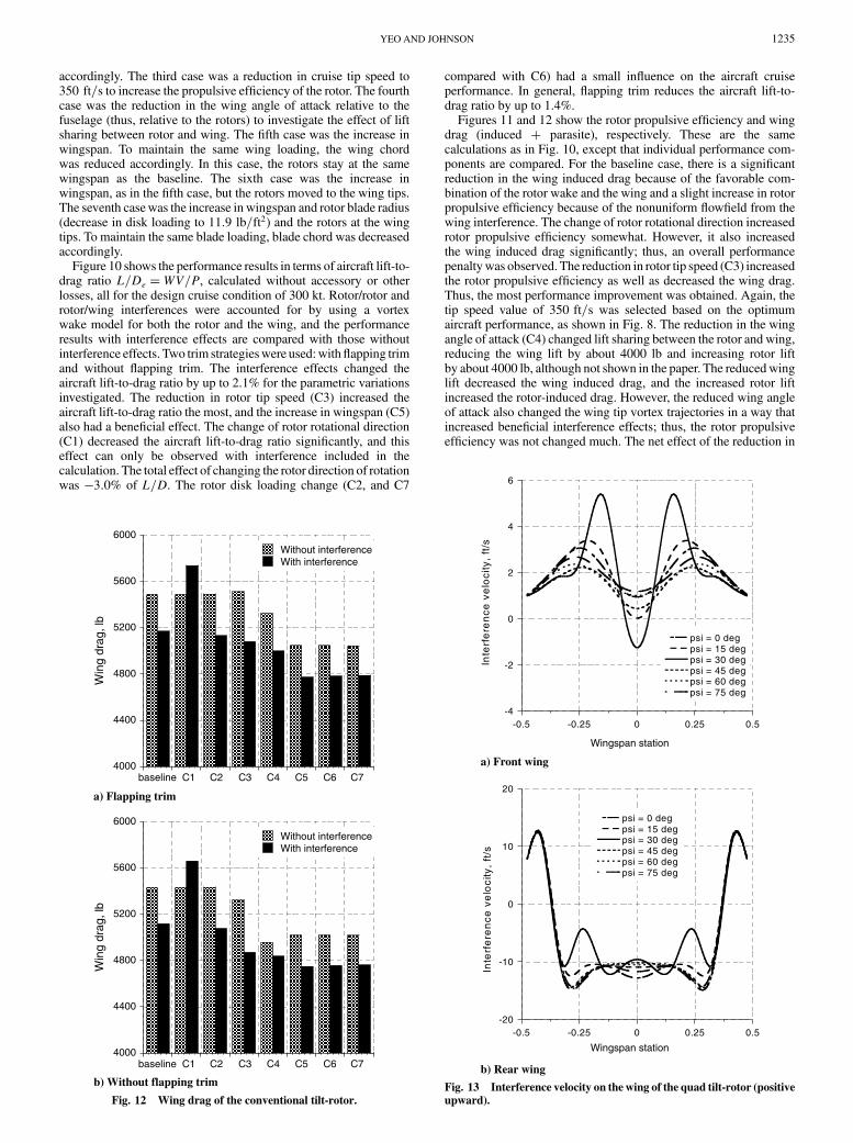
accordingly. The third case was a reduction in cruise tip speed to350 ft=s to increase the propulsive efficiency of the rotor. The fourthcase was the reduction in the wing angle of attack relative to thefuselage (thus, relative to the rotors) to investigate the effect of liftsharing between rotor and wing. The fifth case was the increase inwingspan. To maintain the same wing loading, the wing chordwas reduced accordingly. In this case, the rotors stay at the samewingspan as the baseline. The sixth case was the increase inwingspan, as in the fifth case, but the rotors moved to the wing tips.The seventh casewas the increase in wingspan and rotor blade radius(decrease in disk loading to 11:9 lb=ft2) and the rotors at the wingtips. To maintain the same blade loading, blade chord was decreasedaccordingly.
Figure 10 shows the performance results in terms of aircraft lift-to-drag ratio L=De �WV=P, calculated without accessory or otherlosses, all for the design cruise condition of 300 kt. Rotor/rotor androtor/wing interferences were accounted for by using a vortexwake model for both the rotor and the wing, and the performanceresults with interference effects are compared with those withoutinterference effects. Two trim strategieswere used:withflapping trimand without flapping trim. The interference effects changed theaircraft lift-to-drag ratio by up to 2.1% for the parametric variationsinvestigated. The reduction in rotor tip speed (C3) increased theaircraft lift-to-drag ratio the most, and the increase in wingspan (C5)also had a beneficial effect. The change of rotor rotational direction(C1) decreased the aircraft lift-to-drag ratio significantly, and thiseffect can only be observed with interference included in thecalculation. The total effect of changing the rotor direction of rotationwas �3:0% of L=D. The rotor disk loading change (C2, and C7
compared with C6) had a small influence on the aircraft cruiseperformance. In general, flapping trim reduces the aircraft lift-to-drag ratio by up to 1.4%.
Figures 11 and 12 show the rotor propulsive efficiency and wingdrag (induced � parasite), respectively. These are the samecalculations as in Fig. 10, except that individual performance com-ponents are compared. For the baseline case, there is a significantreduction in the wing induced drag because of the favorable com-bination of the rotor wake and the wing and a slight increase in rotorpropulsive efficiency because of the nonuniform flowfield from thewing interference. The change of rotor rotational direction increasedrotor propulsive efficiency somewhat. However, it also increasedthe wing induced drag significantly; thus, an overall performancepenaltywas observed. The reduction in rotor tip speed (C3) increasedthe rotor propulsive efficiency as well as decreased the wing drag.Thus, the most performance improvement was obtained. Again, thetip speed value of 350 ft=s was selected based on the optimumaircraft performance, as shown in Fig. 8. The reduction in the wingangle of attack (C4) changed lift sharing between the rotor and wing,reducing the wing lift by about 4000 lb and increasing rotor liftby about 4000 lb, although not shown in the paper. The reducedwinglift decreased the wing induced drag, and the increased rotor liftincreased the rotor-induced drag. However, the reduced wing angleof attack also changed the wing tip vortex trajectories in a way thatincreased beneficial interference effects; thus, the rotor propulsiveefficiency was not changed much. The net effect of the reduction in
4000
4400
4800
5200
5600
6000
Without interferenceWith interference
Win
gdr
ag,l
b
baseline C1 C2 C3 C4 C5 C6 C7
a) Flapping trim
4000
4400
4800
5200
5600
6000
Without interferenceWith interference
Win
gdr
ag,l
b
baseline C1 C2 C3 C4 C5 C6 C7
b) Without flapping trim
Fig. 12 Wing drag of the conventional tilt-rotor.
-4
-2
0
2
4
6
-0.5 -0.25 0 0.25 0.5
psi = 0 degpsi = 15 degpsi = 30 degpsi = 45 degpsi = 60 degpsi = 75 deg
Inte
rfe
ren
ceve
loci
ty,
ft/s
Wingspan station
Wingspan station
a) Front wing
-20
-10
0
10
20
-0.5 -0.25 0 0.25 0.5
psi = 0 degpsi = 15 degpsi = 30 degpsi = 45 degpsi = 60 degpsi = 75 deg
Inte
rfe
ren
ceve
loci
ty,
ft/s
b) Rear wing
Fig. 13 Interference velocity on the wing of the quad tilt-rotor (positive
upward).
YEO AND JOHNSON 1235

wing angle of attack was a performance improvement. The increasein wingspan (C5, and decrease of wing chord) decreased the wingdrag (mostly induced drag), but slightly decreased the rotor pro-pulsive efficiency. When the rotor moved to the wing tip (C6) for theincreased wingspan (C5), wing drag was reduced due to increasedbeneficial interference effects.
Quad Tilt-Rotor
Performance results for the quad tilt-rotor configuration arediscussed in this section. Figures 13–15 show the interference effectson the front and rear wings at the design cruise condition of 300 kt.The interference velocity from the rotors on the wings is shown inFig. 13. Again, the interference varied with rotor azimuth andexhibited a 4=rev variation due to the four-bladed rotors. Theinterference on the front wing is similar to that of a conventional tilt-rotor. Themaximum interference on the front wingwas observed at a30 deg azimuth angle, at which the blade tip vortex of the rotor passesthe wing quarter chord line. The interference velocity values on thefront wing are mostly positive due to positive interference velocitiesfrom the rear wing. The interference on the rear wing is verycomplicated because several sources affect it. The most dominantinfluence comes from the front wing and determines the W-shapedistribution. The two humps at �0:25 originate from the two rearrotors. These interference velocities reduce the total induced velocityalong the front wingspan and significantly increase the total induced
velocity along the rear wingspan, as shown in Fig. 14. Even withoutinterference, the induced-velocity distribution of the rear wing issomewhat different from the front wing because of the increasedchord near the midspan. The interference has a beneficial effect onthe front wing performance, but degrades the rear wing performance,as shown in Fig. 15. The interference effect did not change wingprofile power.
-25
-20
-15
-10
-5
0
-0.5 -0.25 0 0.25 0.5
Without interference
With interference
To
tali
nd
uce
dve
loci
ty,
ft/s
Wingspan station
Wingspan station
a) Front wing
-25
-20
-15
-10
-5
0
-0.5 -0.25 0 0.25 0.5
Without interference
With interferenceTo
tali
nd
uce
dve
loci
ty,
ft/s
b) Rear wingFig. 14 Total induced velocity on the wing of the quad tilt-rotor
(positive upward).
0
10
20
30
-0.5 -0.25 0 0.25 0.5
Win
gse
ctio
np
ow
er,
hp/f
t
Wingspan station
Wingspan station
total induced power
profile power
Without interferenceWith interference
a) Front wing
0
10
20
30
-0.5 -0.25 0 0.25 0.5
Win
gse
ctio
np
ow
er,
hp/f
t
total induced power
profile power
Without interferenceWith interference
b) Rear wing
Fig. 15 Wing section power of quad tilt-rotor.
+ 810 - 127
- 110- 110
- 18- 83- 83- 18
- 11- 56- 11 - 56
+ 6+ 6
+ 36 + 36
front
rear
Fig. 16 Interference effect on required power of the quad tilt-rotor;
dimensions are in horsepower.
1236 YEO AND JOHNSON

Figure 16 quantifies the interference effect on the aircraft cruiseperformance for the baseline configuration. The required powerchanges due to interference are shown. The arrows indicate thedirection of interference, and the numbers next to the arrowsrepresent the changes in required power due to interference. Positivenumbers mean unfavorable interference, and negative numbersbeneficial interference. For example, the�6 next to the arrow from“front” to “rear”means that the rear left rotor requires additional 6 hpdue to interference from the front left rotor. The interference effectsbetween the front rotors and the front wing and between the rearrotors and the rear wing reduce required power. The front wing has abeneficial influence on the rear rotor power. The rear wing also has abeneficial influence on the front wing (positive interference velocityreduced total induced velocity and, thus, reduced wing inducedpower). The front rotors increase both the rear rotor power and rearwing power, although the effect is not significant. Themost dominanteffect is from the front wing to the rear wing. It increases the required
power of the rear wing by 810 hp (negative interference velocityincreased total induced velocity and, thus, increased wing inducedpower at most of the wingspan) and, thus, increases the aircraft totalrequired power.
As the vortex core size grows with time (wake age) due to viscousdiffusion, the effects of vortex core size on the aircraft performancewas investigated. It should be noted that the constant vortex coreradius of 20% chord (0.2c) was used for all the calculations shown inthis paper. Without knowing an accurate core growth rate, a simpleway to examine the effect of core growth is to use a larger core size for
0.74
0.76
0.78
0.80
0.82
0.84
0.86
0.88
front rotorrear rotor
Ro
tor
pro
pu
lsiv
ee
ffic
ien
cy
baseline (0.2c) 0.5c 1.0c
Vortex core size
a) Rotor propulsive efficiency
0
1000
2000
3000
4000
5000
front wingrear wing
Win
gd
rag
,lb
Vortex core size
baseline (0.2c) 0.5c 1.0c
b) Wing drag
Fig. 17 Effects of vortex core size on aircraft performance.
front
rear
rear
Baseline
rear
rear
Case 4 (C4)
Case 5 (C5)
Case 6 (C6)
Fig. 18 Rear rotor and wing geometry variations for the quad tilt-
rotor.
6.4
6.6
6.8
7.0
7.2
7.4
7.6
7.8Without interferenceWith interference
Air
cra
ftL
/De
=W
V/P
baseline C1 C2 C3 C4 C5 C6 C7
Fig. 19 Aircraft lift-to-drag ratio of the quad tilt-rotor.
Table 4 Parametric variations of quad tilt-rotor
Case 1 (C1) Change of rotor rotational directionCase 2 (C2) Reduction in cruise rotor tip speed to 350 ft=sCase 3 (C3) Reduction in wing chord to obtain wing loading of 100 lb=ft2
Case 4 (C4) Rear rotors moved inboard to make them directly behind front rotorsCase 5 (C5) Rear rotors moved inboard and rear wingspan decreased to match front wingspanCase 6 (C6) Increase in rear wingspan by 20% and rear rotors moved to the wing tipCase 7 (C7) Rear rotors and wings moved down to the same height as front rotors and wings
YEO AND JOHNSON 1237

both rotors and wings when the interference velocity is calculated.Figure 17 shows the effects of vortex core size on the rotor propulsiveefficiency and wing drag. The calculations were made with twovortex core sizes (0.5 and 1.0c), and the results are comparedwith thebaseline values. As the vortex core size increases, the front rotorpropulsive efficiency increases and the rear wing drag decreases.However, the rear rotor propulsive efficiency decreases and the frontwing drag slightly increases at the same time. Thus, the total effectof changing the vortex core size on the aircraft performance isnegligible.
A parametric study was conducted to understand the effects ofdesign parameters on the performance of the aircraft. Table 4 showsthe design parameters investigated, and the rear rotor and winggeometry variations are illustrated in Fig. 18. The first case was thechange of rotor rotational direction. The second case was thereduction in cruise tip speed for all four rotors, to increase thepropulsive efficiency of the rotor. The third case was reduction inboth front and rear wing chords to obtain a wing loading ofW=S� 100 lb=ft2, which is the value for the conventional tilt-rotor.In this case, the wingspan was maintained the same as the baselinevalue. The fourth case was rear rotors moved inboard to make themdirectly behind the front rotors. The fifth case was rear rotors movedinboard as in the fourth case, but the rear wingspan decreased tomatch front wingspan (from 102.6 to 73.3 ft). To maintain the samewing loading, the wing chord was increased accordingly. The sixthcase was an increase in the rear wingspan by 20% (from 102.6to 123.1 ft) and rear rotors moved to the wing tip. To maintain thesame wing loading, the wing chord was decreased accordingly. The
seventh case was the rear rotors and wings moved down to the sameheight as the front rotors and wings (baseline separation is 5.02 ft).
Figure 19 shows the performance results in terms of aircraft lift-to-drag ratio L=De �WV=P, calculated without accessory or otherlosses, all for the design cruise condition of 300 kt. The performancewas calculated using nonuniform inflow with prescribed wakegeometry. Rotor/rotor, rotor/wing, and wing/wing interference wasaccounted for by using a vortex wake model for both the rotors andthe wings, and the performance results with interference effects arecompared with those without interference effects. Zero flapping trimwas used for all the results for the quad tilt-rotor. The interferenceeffects changed the aircraft lift-to-drag ratio by up to 7.8% for theparametric variations investigated. The reduction in rotor tip speed(C2) and increase in wing loading (C3) increased the aircraft lift-to-drag ratio the most, and the increase in rear wingspan (C6 comparedwith C5) also has a beneficial effect. The change of rotor rotationaldirection (C1) and the move of the rear rotors and wings to the sameheight as the front rotors andwings (C7) decreased the aircraft lift-to-drag ratio significantly, and these effects can only be observed withinterference included in the calculation. The move of the front rotorsinboard (C4) has a negligible influence on the aircraft lift-to-dragratio; however, the reduction in rear wingspan (C5) significantlyreduced the aircraft lift-to-drag ratio.
Figures 20 and 21 show the rotor propulsive efficiency and wingdrag, respectively. These are the same calculations as in Fig. 19,except that individual performance components are compared. Forthe baseline case, there is a reduction in the front-wing induced dragand a significant increase in the rear-wing induced drag because ofthe nonuniform flowfield from the rotor and wing interference and a
0.72
0.76
0.80
0.84
0.88
0.92
Without interferenceWith interference
baseline C1 C2 C3 C4 C5 C6 C7
a) Front rotor
b) Rear rotor
0.72
0.76
0.80
0.84
0.88
0.92Without interferenceWith interference
Rea
r ro
tor
prop
ulsi
ve e
ffici
ency
Fron
t rot
or p
ropu
lsiv
e ef
ficie
ncy
baseline C1 C2 C3 C4 C5 C6 C7
Fig. 20 Rotor propulsive efficiency of the quad tilt-rotor.
2000
2500
3000
3500
4000
4500
5000
5500
Without interferenceWith interference
Fron
t win
g dr
ag, l
bR
ear
win
g dr
ag, l
b
baseline C1 C2 C3 C4 C5 C6 C7
a) Front wing
b) Rear wing
2000
2500
3000
3500
4000
4500
5000
5500
Without interferenceWith interference
baseline C1 C2 C3 C4 C5 C6 C7
Fig. 21 Wing drag of the quad tilt-rotor.
1238 YEO AND JOHNSON

slight reduction in the front rotor propulsive efficiency and anincrease in rear rotor propulsive efficiency because of the com-bination of the interference and the front rotor thrust decrease andrear rotor thrust increase. The change of rotor rotational direction(C1) increased the front rotor propulsive efficiency. However, it alsoincreased the wing drag significantly; thus, an overall performancepenaltywas observed. The reduction in rotor tip speed (C2) increasedthe rotor propulsive efficiency as well as decreased the wing drag.Thus, the most performance improvement was obtained. Theincrease in wingspan (C6 compared with C5) decreased the wingdrag, but slightly decreased the rotor propulsive efficiency.
Without interference effect, the front wing drag values did notchange with the parametric variations except for the wing loadingchange (C3). With interference effect, the change of rotor rotationaldirection (C1) increased the front wing drag significantly, as for theconventional tilt-rotor. The increase in wing loading (C3, wing chordwas reduced with same span as baseline) significantly reduced thefront wing drag. The significant drag reduction came from profiledrag reduction due to the reduced chord. However, induced dragslightly increased.
The rear wing drag values showed significant variations with theparametric variations, and the rear wing drag values always increasedwith the interference effects for the parametric variations investi-gated. The biggest penalty came from the reduction in the rearwingspan (C5) due to the increased induced and interference drag.The biggest benefit came from the increase in wing loading (C3) andthe increase in the rear wingspan (C6 compared with C5). However,the reasons for thewing performance improvement are different. Theincrease inwing loading (C3) resulted in the reduction in profile drag,but the increase in the rear wingspan (C5) resulted in the reduction ininduced and interference drag.
Conclusions
A performance and design investigation was conduced for146,600 lb conventional and quad tilt-rotors, which are to cruise at300 kt at a 4000 ft=95�F condition. The aerodynamic interferenceeffects were included in the comprehensive calculations to betterunderstand the physics and to quantify the effects on the aircraftdesign.
From this study, the following conclusions were obtained.Conventional tilt-rotor1) Interference effect improves the aircraft lift-to-drag ratio of the
baseline conventional tilt-rotor. The interference velocities reducethe total induced velocity along the wingspan and, thus, reduce winginduced power.
2) The reduction in rotor tip speed increased the aircraft lift-to-drag ratio the most among the design parameters investigated, andthe increase in wingspan also has a beneficial effect on aircraftperformance.
3) The change of rotor rotational direction decreased the aircraftlift-to-drag ratio significantly, and this effect can only be observedwith interference included in the calculation.
Quad tilt-rotor1) Interference effect degrades the aircraft performance of the
baseline quad tilt-rotor. The most dominant unfavorable effect isfrom the front wing to the rear wing; it increases the rear wing total
induced power significantly and, thus, decreases the aircraft lift-to-drag ratio.
2) The reduction in rotor tip speed and increase in wing loadingincreased the aircraft lift-to-drag ratio the most among the designparameters investigated.
3) The change of rotor rotational direction decreased the aircraftlift-to-drag ratio significantly, and this effect can only be observedwith interference included in the calculation.
References
[1] Johnson, W., Yamauchi, G. K., and Watts, M. E., “Design andTechnology Requirements for Civil Heavy Lift Rotorcraft,”Proceedings of the American Helicopter Society Vertical Lift Aircraft
Design Conference, American Helicopter Society, Alexandria, VA,Jan. 2006.
[2] Felker, F. F., Maisel, M. D., and Betzina, M. D., “Full-Scale Tilt-RotorHover Performance,” Journal of the American Helicopter Society,Vol. 31, No. 2, April 1986, pp. 10–18.
[3] Felker, F. F., and Light, J. S., “Aerodynamic Interactions Between aRotor andWing in Hover,” Journal of the American Helicopter Society,Vol. 33, No. 2, April 1988, pp. 53–61.doi:10.4050/JAHS.33.53
[4] Wood, T. L., and Peryea, M. A., “Reduction of Tiltrotor Download,”Journal of the American Helicopter Society, Vol. 40, No. 3, July 1995,pp. 42–51.doi:10.4050/JAHS.40.42
[5] McVeigh, M. A., Grauer, W. K., and Paisley, D. J., “Rotor/AirframeInteractions on Tiltrotor Aircraft,” Journal of the American HelicopterSociety, Vol. 35, No. 3, July 1990, pp. 43–51.doi:10.4050/JAHS.35.43
[6] Snyder, D., “The Quad Tiltrotor: Its Beginning and Evolution,”Proceedings of the American Helicopter Society 56th Annual Forum,American Helicopter Society, Alexandria, VA, May 2000, pp. 48–61.
[7] Radhakrishnan, A., and Schmitz, F. H., “AnExperimental Investigationof a Quad Tilt Rotor in Ground Effect,” AIAA Paper 2003-3517,June 2003.
[8] Radhakrishnan, A., and Schmitz, F. H., “QuadTilt Rotor Download andPower Measurements in Ground Effect,” AIAA Paper 2006-3471,June 2006.
[9] Gupta, V., and Baeder, J. D., “Quad Tiltrotor Aerodynamics in GroundEffect,” Proceedings of the American Helicopter Society 58th Annual
Forum, American Helicopter Society, Alexandria, VA, June 2002.[10] Gupta, V., and Baeder, J. D., “Investigation of Quad Tiltrotor
Aerodynamics in Forward FlightUsingCFD,”AIAAPaper 2002-2812,June 2002.
[11] Preston, J., and Peyran, R., “Linking a Solid-Modeling Capability witha Conceptual Rotorcraft Sizing Code,” Proceedings of the American
Helicopter Society Vertical Lift Aircraft Design Conference, AmericanHelicopter Society, Alexandria, VA, Jan. 2000.
[12] Johnson, W., “Technology Drivers in the Development of CAMRADII,” American Helicopter Society Paper PS.3 Jan. 1994.
[13] Johnson, W., “Calculation of Tilt Rotor Aeroacoustic Model (TRAMDNW) Performance, Airloads, and Structural Loads,” Proceedings ofthe American Helicopter Society Aeromechanics Specialists’Meeting,American Helicopter Society, Alexandria, VA, Nov. 2000.
[14] Potsdam, M., Yeo, H., and Johnson, W., “Rotor Airloads PredictionUsing Loose Aerodynamic/Structural Coupling,” Journal of Aircraft,Vol. 43, No. 3, May–June 2006, pp. 732–742.doi:10.2514/1.14006
[15] Drees, J. M., “Prepare for the 21st Century—The 1987 Alexander A.NikolskyLecture,” Journal of theAmericanHelicopter Society, Vol. 32,No. 3, July 1987, pp. 3–14.
YEO AND JOHNSON 1239