Pendulum-CNT-90 Timer-Counter-Analyzer rev26 high performance CNT-90 timer/counter/analyzer...
4
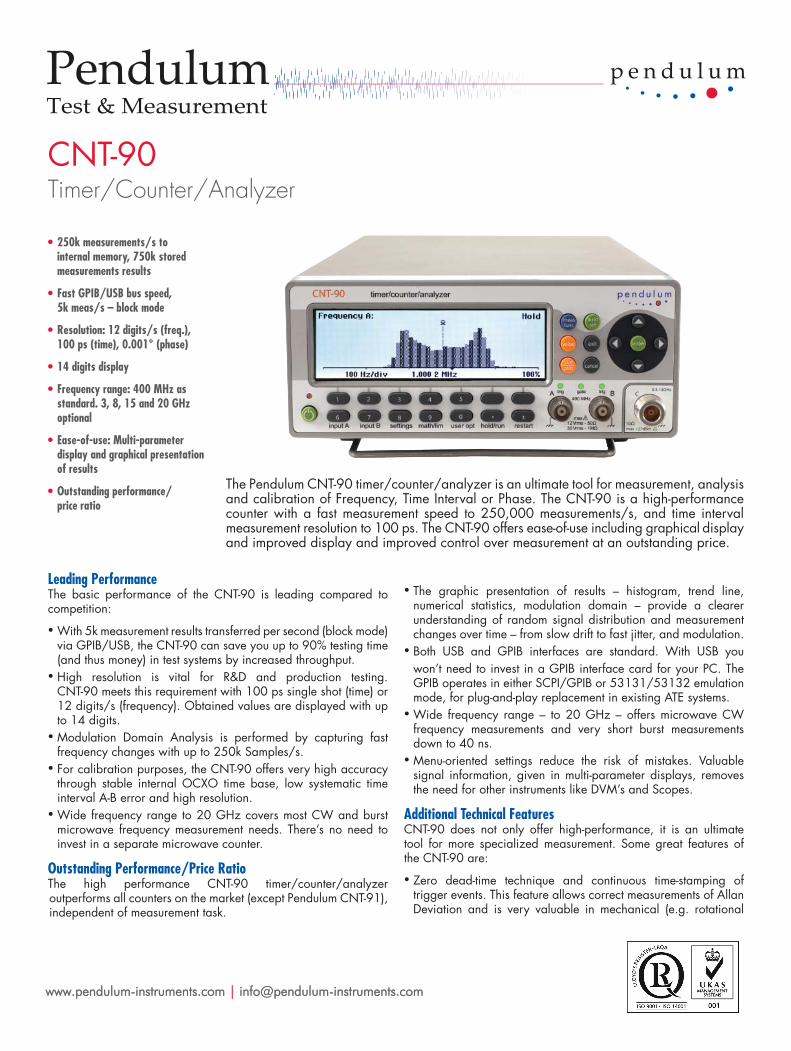
CNT-90 Timer/Counter/Analyzer Leading Performance The basic performance of the CNT-90 is leading compared to competition: • With 5k measurement results transferred per second (block mode) via GPIB/USB, the CNT-90 can save you up to 90% testing time (and thus money) in test systems by increased throughput. • High resolution is vital for R&D and production testing. CNT-90 meets this requirement with 100 ps single shot (time) or 12 digits/s (frequency). Obtained values are displayed with up to 14 digits. • Modulation Domain Analysis is performed by capturing fast frequency changes with up to 250k Samples/s. • For calibration purposes, the CNT-90 offers very high accuracy through stable internal OCXO time base, low systematic time interval A-B error and high resolution. • Wide frequency range to 20 GHz covers most CW and burst microwave frequency measurement needs. There’s no need to invest in a separate microwave counter. Outstanding Performance/Price Ratio The high performance CNT-90 timer/counter/analyzer outperforms all counters on the market (except Pendulum CNT-91), independent of measurement task. • The graphic presentation of results – histogram, trend line, numerical statistics, modulation domain – provide a clearer understanding of random signal distribution and measurement changes over time – from slow drift to fast jitter, and modulation. • Both USB and GPIB interfaces are standard. With USB you won’t need to invest in a GPIB interface card for your PC. The GPIB operates in either SCPI/GPIB or 53131/53132 emulation mode, for plug-and-play replacement in existing ATE systems. • Wide frequency range – to 20 GHz – offers microwave CW frequency measurements and very short burst measurements down to 40 ns. • Menu-oriented settings reduce the risk of mistakes. Valuable signal information, given in multi-parameter displays, removes the need for other instruments like DVM’s and Scopes. Additional Technical Features CNT-90 does not only offer high-performance, it is an ultimate tool for more specialized measurement. Some great features of the CNT-90 are: • Zero dead-time technique and continuous time-stamping of trigger events. This feature allows correct measurements of Allan Deviation and is very valuable in mechanical (e.g. rotational The Pendulum CNT-90 timer/counter/analyzer is an ultimate tool for measurement, analysis and calibration of Frequency, Time Interval or Phase. The CNT-90 is a high-performance counter with a fast measurement speed to 250,000 measurements/s, and time interval measurement resolution to 100 ps. The CNT-90 offers ease-of-use including graphical display and improved display and improved control over measurement at an outstanding price. www.pendulum-instruments.com | [email protected]
Transcript of Pendulum-CNT-90 Timer-Counter-Analyzer rev26 high performance CNT-90 timer/counter/analyzer...
CNT-90Timer/Counter/Analyzer
Leading PerformanceThe basic performance of the CNT-90 is leading compared to competition:
• With 5k measurement results transferred per second (block mode)via GPIB/USB, the CNT-90 can save you up to 90% testing time(and thus money) in test systems by increased throughput.
• High resolution is vital for R&D and production testing.CNT-90 meets this requirement with 100 ps single shot (time) or12 digits/s (frequency). Obtained values are displayed with upto 14 digits.
• Modulation Domain Analysis is performed by capturing fastfrequency changes with up to 250k Samples/s.
• For calibration purposes, the CNT-90 offers very high accuracythrough stable internal OCXO time base, low systematic timeinterval A-B error and high resolution.
• Wide frequency range to 20 GHz covers most CW and burstmicrowave frequency measurement needs. There’s no need toinvest in a separate microwave counter.
Outstanding Performance/Price RatioThe high performance CNT-90 timer/counter/analyzer outperforms all counters on the market (except Pendulum CNT-91), independent of measurement task.
• The graphic presentation of results – histogram, trend line,numerical statistics, modulation domain – provide a clearerunderstanding of random signal distribution and measurementchanges over time – from slow drift to fast jitter, and modulation.
• Both USB and GPIB interfaces are standard. With USB youwon’t need to invest in a GPIB interface card for your PC. TheGPIB operates in either SCPI/GPIB or 53131/53132 emulationmode, for plug-and-play replacement in existing ATE systems.
• Wide frequency range – to 20 GHz – offers microwave CWfrequency measurements and very short burst measurementsdown to 40 ns.
• Menu-oriented settings reduce the risk of mistakes. Valuablesignal information, given in multi-parameter displays, removesthe need for other instruments like DVM’s and Scopes.
Additional Technical FeaturesCNT-90 does not only offer high-performance, it is an ultimate tool for more specialized measurement. Some great features of the CNT-90 are:
• Zero dead-time technique and continuous time-stamping oftrigger events. This feature allows correct measurements of AllanDeviation and is very valuable in mechanical (e.g. rotational
The Pendulum CNT-90 timer/counter/analyzer is an ultimate tool for measurement, analysis and calibration of Frequency, Time Interval or Phase. The CNT-90 is a high-performance counter with a fast measurement speed to 250,000 measurements/s, and time interval measurement resolution to 100 ps. The CNT-90 offers ease-of-use including graphical display and improved display and improved control over measurement at an outstanding price.
www.pendulum-instruments.com | [email protected]
• Battery backup acting as a built in UPS (UninterruptedPower Supply)
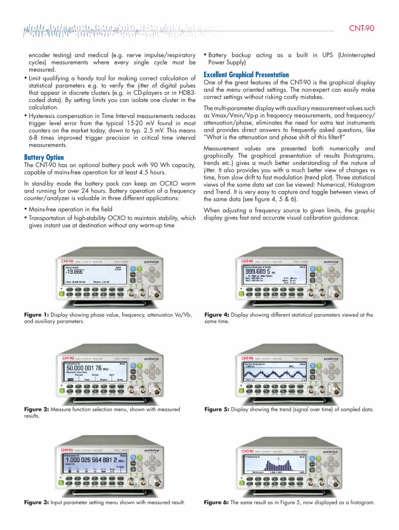
Excellent Graphical PresentationOne of the great features of the CNT-90 is the graphical display and the menu oriented settings. The non-expert can easily make correct settings without risking costly mistakes.
The multi-parameter display with auxiliary measurement values such as Vmax/Vmin/Vp-p in frequency measurements, and frequency/attenuation/phase, eliminates the need for extra test instruments and provides direct answers to frequently asked questions, like “What is the attenuation and phase shift of this fi lter?”
Measurement values are presented both numerically and graphically. The graphical presentation of results (histograms, trends etc.) gives a much better understanding of the nature of jitter. It also provides you with a much better view of changes vs time, from slow drift to fast modulation (trend plot). Three statistical views of the same data set can be viewed: Numerical, Histogram and Trend. It is very easy to capture and toggle between views of the same data (see fi gure 4, 5 & 6).
When adjusting a frequency source to given limits, the graphic display gives fast and accurate visual calibration guidance.
Figure 1: Display showing phase value, frequency, attenuation Va/Vb, and auxiliary parameters.
Figure 2: Measure function selection menu, shown with measured results.
Figure 3: Input parameter setting menu shown with measured result.
Figure 4: Display showing different statistical parameters viewed at the same time.
Figure 5: Display showing the trend (signal over time) of sampled data.
Figure 6: The same result as in Figure 5, now displayed as a histogram.
encoder testing) and medical (e.g. nerve impulse/respiratory cycles) measurements where every single cycle must be measured.
• Limit qualifying a handy tool for making correct calculation ofstatistical parameters e.g. to verify the jitter of digital pulses that appear in discrete clusters (e.g. in CD-players or in HDB3-coded data). By setting limits you can isolate one cluster in the calculation.
• Hysteresis compensation in Time Interval measurements reducestrigger level error from the typical 15-20 mV found in mostcounters on the market today, down to typ. 2.5 mV. This means6-8 times improved trigger precision in critical time intervalmeasurements.
Battery OptionThe CNT-90 has an optional battery pack with 90 Wh capacity, capable of mains-free operation for at least 4.5 hours.
In stand-by mode the battery pack can keep an OCXO warm and running for over 24 hours. Battery operation of a frequency counter/analyzer is valuable in three different applications:
• Mains-free operation in the fi eld• Transportation of high-stability OCXO to maintain stability, which
gives instant use at destination without any warm-up time
CNT-90
Measuring FunctionsAll measurements are displayed with a large main parameter value and smaller auxiliary parameter values (with less resolution). Some measurements are only available as auxiliary parameters.
Frequency A, B, CRange: Input A, B: 0.002 Hz to 400 MHzInput C (option): Up to 3, 8, 15 or 20 GHzResolution: 12 digits in 1s measuring time (normal)Aux. Parameter (A, B): Vmax, Vmin, Vp-p
Frequency Burst A, B, C (opt. 14/14B)Frequency and PRF of repetitive burst signals can be measured without external control signal and with selectable start arming delay.Functions: Frequency in burst (in Hz); PRF (in Hz)Range: Input A, B, C: See Frequency spec.Minimum Burst Duration: Down to 40 nsMinimum Pulses in Burst:Input A or B: 3 (6 above 160 MHz)Input C: 3 x prescaler factorPRF Range: 0.5 Hz to 1MHzStart Delay: 10 ns to 2sec., 10 ns resolutionAux. Parameter: PRF
Period A, B, CMode: Single, AverageRange: Input A, B: 2.5 ns to 1000 sec. (single, average)Input C (option): 10 ns down to 330, 125, 70 or 50 psResolution: 100 ps (single); 12 digits/s (avg)Aux. Parameter (A, B): Vmax, Vmin, Vp-p
Ratio A/B, B/A, C/A, C/BRange: (10-9) to 1011
Input Frequency: Input A, B: 0.1 Hz to 400 MHzInput C (option): Up to 3, 8, 15 or 20 GHzAux Parameters: Freq 1, Freq 2
Time Interval A to B, B to A, A to A, B to BRange: Normal Calculation: 0ns to +106 sec.Smart Calculation: -106 sec. to +106 sec.Resolution: 100 psMin. Pulse Width: 1.6 nsSmart Calculation: Smart Time Interval to determine sign (A before B or A after B)
Positive and Negative Pulse Width A, BRange: 2.3 ns to 106 sec.Min. Pulse Width: 2.3 nsAux. Parameters: Vmax,Vmin, Vp-p
Rise and Fall Time A, BRange: 1.5 ns to 106 sec.Trigger Levels: 10% and 90% of signal Vp-pMin. Pulse Width: 1.6 nsAux. Parameters: Slew rate, Vmax, Vmin
Positive and Negative Duty Factor A, BRange: 0.000001 to 0.999999Freq. Range: 0.1 Hz to 300 MHzAux. parameters: Period, pulse width
Phase A Relative B, B Relative ARange: -180° to +360°Resolution: Single-cycle: 0.001° to 10 kHz, decreasing to 1° >10 MHz. Resolution can be improved via averaging (statistics)
Freq. Range: up to 160 MHzAux. Parameters: Freq (A), Va/Vb (in dB)
Vmax, Vmin, Vp-p A, BRange: -50 V to +50 V, -5V to +5VRange is limited by the specifi cation for max input voltage without damage (see input A, B)Freq. Range: DC, 1Hz to 300 MHzMode: Vmax, Vmin, Vp-pResolution: 2.5 mVUncertainty (5V range, typical):DC, 1Hz to 1kHz: 1% +15 mV1kHz to 20 MHz: 3% +15 mV20 to 100 MHz: 10% +15 mV100 to 300 MHz: 30% +15 mVAux parameters: Vmin, Vmax, Vp-p
Time stamping A, B, CRaw time stamp data together with pulse counts on inputs A, B or C, accessible via GPIB or USB only.Max Sample Speed: See GPIB specifi cationsMax Frequency: 160 MHzTimestamp Resolution: 70 ps
Input and Output Specifi cationsInputs A and BFrequency Range:DC-Coupled: DC to 400 MHzAC-Coupled: 10 Hz to 400 MHzImpedance:1MΩ // 20 pF or 50 Ω (VSWR ≤2:1)Trigger Slope: Positive or negativeMax. Channel Timing Difference: 500 psSensitivity: DC-200 MHz: 15 mVrms200-300 MHz: 25 mVrms300-400 MHz: 35 mVrmsAttenuation: x1, x10Dynamic Range (x1): 30 mV p-p to10 V p-p within ±5V windowTrigger Level: Read-Out on displayResolution: 3mVUncertainty (x1): ±(15 mV + 1% of trigger level)AUTO Trigger Level: Trigger level is automaticallyset to 50% point of input signal (10% and 90%for Rise/Fall Time)AUTO Hysteresis: Freq. range: 1Hz to 300 MHzTime: Min hysteresis window (hysteresiscompensation)Frequency: One third of input signal amplitudeAnalog LP Filter: Nominal 100kHz, RC-type.Digital LP Filter: 1Hz to 50 MHz cut-offfrequencyMax Voltage Without Damage:1MΩ: 350 V (DC + AC pk) to 440 Hz, falling to12 Vrms at 1MHz.50 Ω: 12 VrmsConnector: BNC
Input C (Option 10)Operating Input Voltage Range opt. 10: 100 to 300 MHz: 20 mVrms (-21 dBm) to 12 Vrms0.3 to 2.5 GHz: 10 mVrms (-27 dBm) to 12 Vrms2.5 to 2.7 GHz: 20 mVrms (-21 dBm) to 12 Vrms2.7 to 3.0 GHz: 40 mVrms (-15 dBm) to 12 VrmsPrescaler Factor: 16Impedance: 50 Ω nominal, VSWR <2.5:1
Max Voltage without Damage:12 Vrms, pin-diode protectedConnector: Type N Female
Input C (Option 13)Operating Input Voltage Range:100 to 200 MHz: 100 mVrms to 7Vrms (typ.) 200 to 300 MHz: 40 mVrms to 7Vrms (typ.)300 to 500 MHz: 20 mVrms to 7Vrms0.5 to 3.0 GHz: 10 mVrms to 7Vrms3.0 to 4.5 GHz: 20 mVrms to 7Vrms4.5 to 6.0 GHz: 40 mVrms to 7Vrms6.0 to 8 GHz: 80 mVrms to 7VrmsPrescaler Factor: 256Impedance: 50 Ω nominal, VSWR <2.5:1 Max Voltage Without Damage: 7Vrms Connector: Type N Female
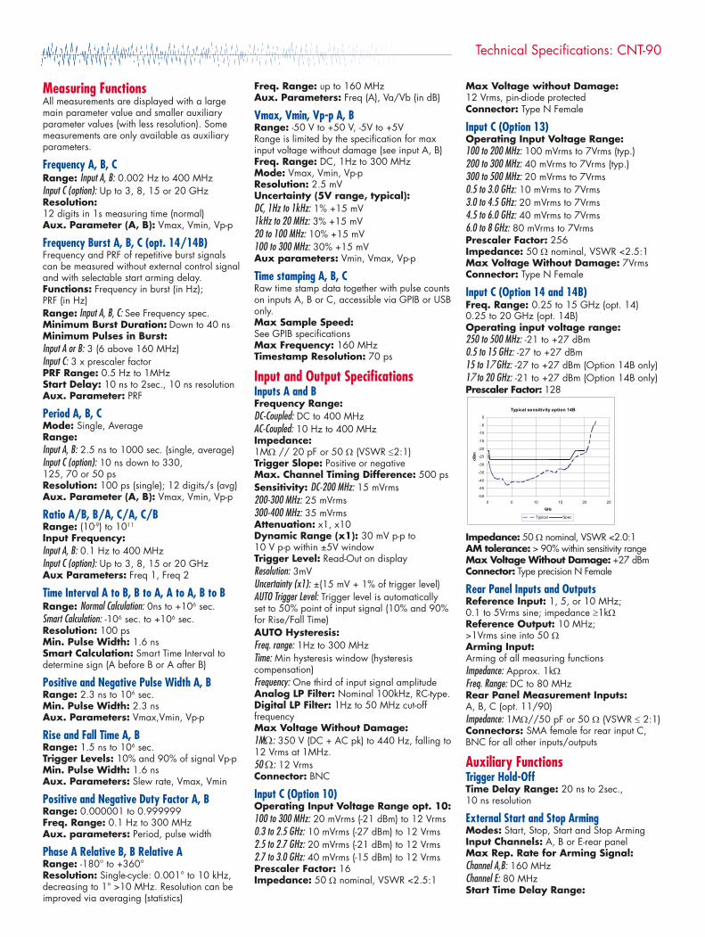
Input C (Option 14 and 14B)Freq. Range: 0.25 to 15 GHz (opt. 14) 0.25 to 20 GHz (opt. 14B)Operating input voltage range:250 to 500 MHz: -21 to +27 dBm0.5 to 15 GHz: -27 to +27 dBm15 to 17 GHz: -27 to +27 dBm (Option 14B only) 17 to 20 GHz: -21 to +27 dBm (Option 14B only) Prescaler Factor: 128
Impedance: 50 Ω nominal, VSWR <2.0:1AM tolerance: > 90% within sensitivity rangeMax Voltage Without Damage: +27 dBmConnector: Type precision N Female
Rear Panel Inputs and OutputsReference Input: 1, 5, or 10 MHz; 0.1 to 5Vrms sine; impedance ≥1kΩReference Output: 10 MHz; >1Vrms sine into 50 ΩArming Input:Arming of all measuring functionsImpedance: Approx. 1kΩFreq. Range: DC to 80 MHzRear Panel Measurement Inputs:A, B, C (opt. 11/90)Impedance: 1MΩ//50 pF or 50 Ω (VSWR ≤ 2:1)Connectors: SMA female for rear input C,BNC for all other inputs/outputs
Auxiliary FunctionsTrigger Hold-OffTime Delay Range: 20 ns to 2sec., 10 ns resolution
External Start and Stop ArmingModes: Start, Stop, Start and Stop ArmingInput Channels: A, B or E-rear panelMax Rep. Rate for Arming Signal:Channel A,B: 160 MHzChannel E: 80 MHzStart Time Delay Range:
Typical sensitivity option 14B
-50
-45
-40
-35
-30
-25
-20
-15
-10
-5
0
0 5 10 15 20 25
GHz
dBm
Typical Spec
Technical Specifications: CNT-90
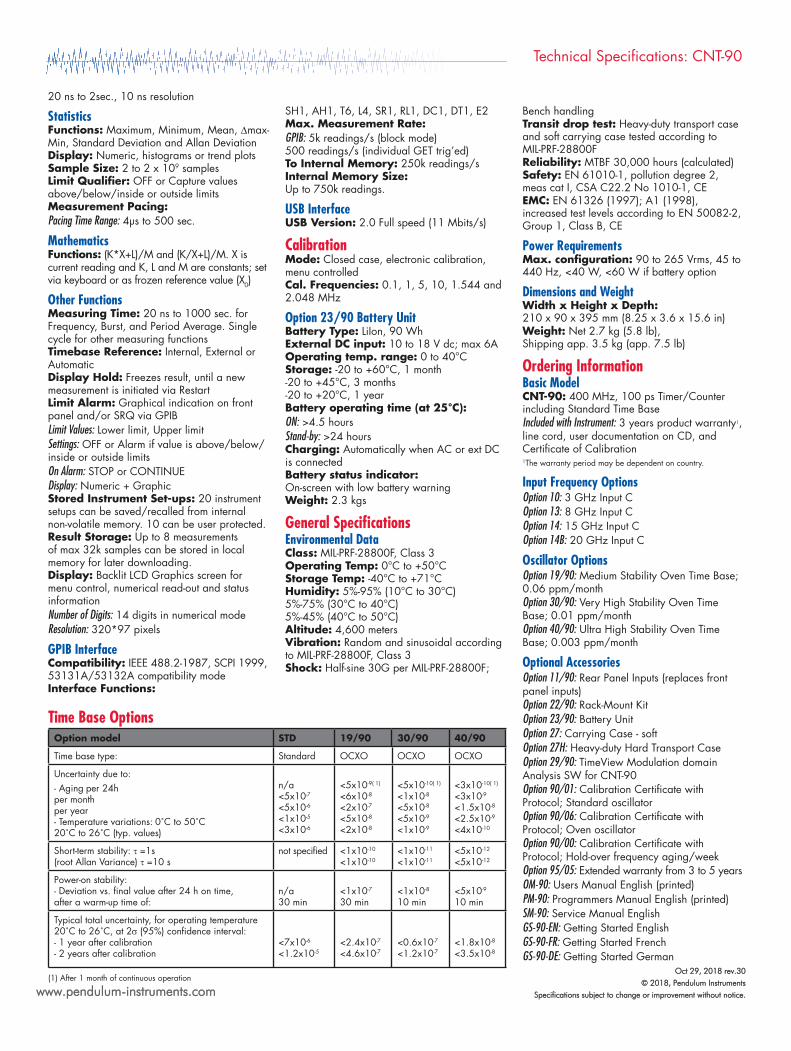
Time Base Options09/0409/0309/91DTSledom noitpO
OXCOOXCOOXCOdradnatS:epyt esab emiT
Uncertainty due to:- Aging per 24hper monthper year- Temperature variations: 0˚C to 50˚C20˚C to 26˚C (typ. values)
n/a<5x10-7
<5x10⁻⁶
<1x10⁻⁵
<3x10⁻⁶
<5x10⁻⁹( 1)
<6x10⁻⁸
<2x10⁻⁷
<5x10⁻⁸
<2x10⁻⁸
<5x10⁻¹⁰( 1)
<1x10⁻⁸
<5x10⁻⁸
<5x10⁻⁹
<1x10⁻⁹
<3x10⁻¹⁰( 1)
<3x10⁻⁹
<1.5x10⁻⁸
<2.5x10⁻⁹
<4x10⁻¹⁰
Short-term stability: τ =1s (root Allan Variance) τ =10 s
not specifi ed <1x10⁻¹⁰
<1x10⁻¹⁰<1x10-11
<1x10-11<5x10-12
<5x10-12
Power-on stability:- Deviation vs. fi nal value after 24 h on time,after a warm-up time of:
n/a30 min
<1x10⁻⁷
30 min<1x10⁻⁸
10 min<5x10⁻⁹
10 min
Typical total uncertainty, for operating temperature 20˚C to 26˚C, at 2σ (95%) confi dence interval:- 1 year after calibration- 2 years after calibration
<7x10⁻⁶
<1.2x10⁻⁵<2.4x10⁻⁷
<4.6x10⁻⁷<0.6x10⁻⁷
<1.2x10⁻⁷<1.8x10⁻⁸
<3.5x10⁻⁸
(1) After 1 month of continuous operation
20 ns to 2sec., 10 ns resolution
StatisticsFunctions: Maximum, Minimum, Mean, ∆max-Min, Standard Deviation and Allan DeviationDisplay: Numeric, histograms or trend plotsSample Size: 2 to 2 x 10⁹ samplesLimit Qualifi er: OFF or Capture values above/below/inside or outside limitsMeasurement Pacing: Pacing Time Range: 4µs to 500 sec.
MathematicsFunctions: (K*X+L)/M and (K/X+L)/M. X is current reading and K, L and M are constants; set via keyboard or as frozen reference value (X0)
Other FunctionsMeasuring Time: 20 ns to 1000 sec. for Frequency, Burst, and Period Average. Single cycle for other measuring functionsTimebase Reference: Internal, External or AutomaticDisplay Hold: Freezes result, until a new measurement is initiated via RestartLimit Alarm: Graphical indication on front panel and/or SRQ via GPIBLimit Values: Lower limit, Upper limitSettings: OFF or Alarm if value is above/below/inside or outside limitsOn Alarm: STOP or CONTINUEDisplay: Numeric + GraphicStored Instrument Set-ups: 20 instrument setups can be saved/recalled from internal non-volatile memory. 10 can be user protected.Result Storage: Up to 8 measurements of max 32k samples can be stored in local memory for later downloading.Display: Backlit LCD Graphics screen for menu control, numerical read-out and status informationNumber of Digits: 14 digits in numerical modeResolution: 320*97 pixels
GPIB InterfaceCompatibility: IEEE 488.2-1987, SCPI 1999, 53131A/53132A compatibility modeInterface Functions:
SH1, AH1, T6, L4, SR1, RL1, DC1, DT1, E2Max. Measurement Rate:GPIB: 5k readings/s (block mode)500 readings/s (individual GET trig’ed)To Internal Memory: 250k readings/sInternal Memory Size: Up to 750k readings.
USB InterfaceUSB Version: 2.0 Full speed (11 Mbits/s)
CalibrationMode: Closed case, electronic calibration, menu controlledCal. Frequencies: 0.1, 1, 5, 10, 1.544 and 2.048 MHz
Option 23/90 Battery UnitBattery Type: LiIon, 90 WhExternal DC input: 10 to 18 V dc; max 6AOperating temp. range: 0 to 40°CStorage: -20 to +60°C, 1 month-20 to +45°C, 3 months-20 to +20°C, 1 yearBattery operating time (at 25°C):ON: >4.5 hoursStand-by: >24 hoursCharging: Automatically when AC or ext DCis connectedBattery status indicator:On-screen with low battery warningWeight: 2.3 kgs
General Specifi cationsEnvironmental DataClass: MIL-PRF-28800F, Class 3Operating Temp: 0°C to +50°CStorage Temp: -40°C to +71°CHumidity: 5%-95% (10°C to 30°C)5%-75% (30°C to 40°C)5%-45% (40°C to 50°C)Altitude: 4,600 metersVibration: Random and sinusoidal according to MIL-PRF-28800F, Class 3Shock: Half-sine 30G per MIL-PRF-28800F;
Technical Specifications: CNT-90
www.pendulum-instruments.com
Bench handlingTransit drop test: Heavy-duty transport case and soft carrying case tested according to MIL-PRF-28800FReliability: MTBF 30,000 hours (calculated) Safety: EN 61010-1, pollution degree 2, meas cat I, CSA C22.2 No 1010-1, CE EMC: EN 61326 (1997); A1 (1998), increased test levels according to EN 50082-2, Group 1, Class B, CE
Power RequirementsMax. confi guration: 90 to 265 Vrms, 45 to 440 Hz, <40 W, <60 W if battery option
Dimensions and WeightWidth x Height x Depth:210 x 90 x 395 mm (8.25 x 3.6 x 15.6 in) Weight: Net 2.7 kg (5.8 lb),Shipping app. 3.5 kg (app. 7.5 lb)
Ordering InformationBasic ModelCNT-90: 400 MHz, 100 ps Timer/Counter including Standard Time BaseIncluded with Instrument: 3 years product warranty1, line cord, user documentation on CD, and Certifi cate of Calibration1The warranty period may be dependent on country.
Input Frequency OptionsOption 10: 3 GHz Input COption 13: 8 GHz Input COption 14: 15 GHz Input COption 14B: 20 GHz Input C
Oscillator OptionsOption 19/90: Medium Stability Oven Time Base; 0.06 ppm/monthOption 30/90: Very High Stability Oven Time Base; 0.01 ppm/monthOption 40/90: Ultra High Stability Oven Time Base; 0.003 ppm/month
Optional AccessoriesOption 11/90: Rear Panel Inputs (replaces front panel inputs)Option 22/90: Rack-Mount KitOption 23/90: Battery UnitOption 27: Carrying Case - softOption 27H: Heavy-duty Hard Transport Case Option 29/90: TimeView Modulation domain Analysis SW for CNT-90Option 90/01: Calibration Certifi cate with Protocol; Standard oscillatorOption 90/06: Calibration Certifi cate with Protocol; Oven oscillatorOption 90/00: Calibration Certifi cate with Protocol; Hold-over frequency aging/week Option 95/05: Extended warranty from 3 to 5 years OM-90: Users Manual English (printed)PM-90: Programmers Manual English (printed) SM-90: Service Manual EnglishGS-90-EN: Getting Started EnglishGS-90-FR: Getting Started FrenchGS-90-DE: Getting Started German
Oct 29, 2018 rev.30© 2018, Pendulum Instruments
Specifications subject to change or improvement without notice.