PEM® brand microPEM® fasteners are ideal for today’s … PEM® brand microPEM® fasteners are...
16
MPF ™ PEM® brand microPEM® fasteners are ideal for today’s and tomorrow’s compact electronics Bulletin MPF-817 Rev 218
-
Upload
vuonghuong -
Category
Documents
-
view
213 -
download
0
Transcript of PEM® brand microPEM® fasteners are ideal for today’s … PEM® brand microPEM® fasteners are...

MPF™
PEM® brand microPEM® fasteners are ideal for today’s and tomorrow’s compact electronics
Bulletin MPF-817Rev 218
MPF-2 PennEngineering • www.pemnet.com
microPEM® FASTENERS
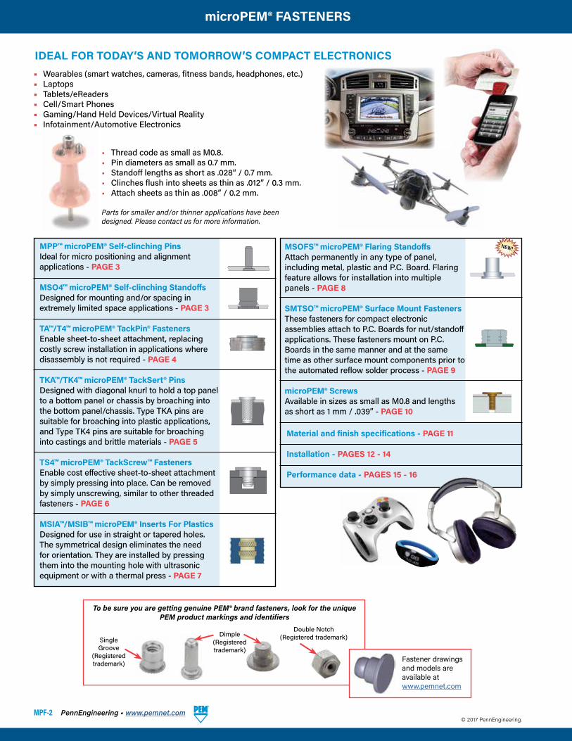
IDEAL FOR TODAY’S AND TOMORROW’S COMPACT ELECTRONICS• Wearables (smart watches, cameras, fitness bands, headphones, etc.)• Laptops• Tablets/eReaders• Cell/Smart Phones• Gaming/Hand Held Devices/Virtual Reality• Infotainment/Automotive Electronics
• Thread code as small as M0.8.• Pin diameters as small as 0.7 mm.• Standoff lengths as short as .028” / 0.7 mm.• Clinches flush into sheets as thin as .012” / 0.3 mm.• Attach sheets as thin as .008” / 0.2 mm.
Parts for smaller and/or thinner applications have been designed. Please contact us for more information.
MPP™ microPEM® Self-clinching PinsIdeal for micro positioning and alignment applications - PAGE 3
MSO4™ microPEM® Self-clinching StandoffsDesigned for mounting and/or spacing in extremely limited space applications - PAGE 3
TA™/T4™ microPEM® TackPin® FastenersEnable sheet-to-sheet attachment, replacing costly screw installation in applications where disassembly is not required - PAGE 4
TKA™/TK4™ microPEM® TackSert® PinsDesigned with diagonal knurl to hold a top panel to a bottom panel or chassis by broaching into the bottom panel/chassis. Type TKA pins are suitable for broaching into plastic applications, and Type TK4 pins are suitable for broaching into castings and brittle materials - PAGE 5
TS4™ microPEM® TackScrew™ FastenersEnable cost effective sheet-to-sheet attachment by simply pressing into place. Can be removed by simply unscrewing, similar to other threaded fasteners - PAGE 6
MSIA™/MSIB™ microPEM® Inserts For PlasticsDesigned for use in straight or tapered holes. The symmetrical design eliminates the need for orientation. They are installed by pressing them into the mounting hole with ultrasonic equipment or with a thermal press - PAGE 7
MSOFS™ microPEM® Flaring StandoffsAttach permanently in any type of panel, including metal, plastic and P.C. Board. Flaring feature allows for installation into multiple panels - PAGE 8
SMTSO™ microPEM® Surface Mount FastenersThese fasteners for compact electronic assemblies attach to P.C. Boards for nut/standoff applications. These fasteners mount on P.C. Boards in the same manner and at the same time as other surface mount components prior to the automated reflow solder process - PAGE 9
microPEM® ScrewsAvailable in sizes as small as M0.8 and lengths as short as 1 mm / .039” - PAGE 10
Material and finish specifications - PAGE 11
Installation - PAGES 12 - 14
Performance data - PAGES 15 - 16
© 2017 PennEngineering.
To be sure you are getting genuine PEM® brand fasteners, look for the unique PEM product markings and identifiers
Dimple(Registered trademark)
SingleGroove
(Registered trademark)
Double Notch(Registered trademark)
Fastener drawings and models are available atwww.pemnet.com
NEW!
PennEngineering • www.pemnet.com MPF-3
microPEM® FASTENERS
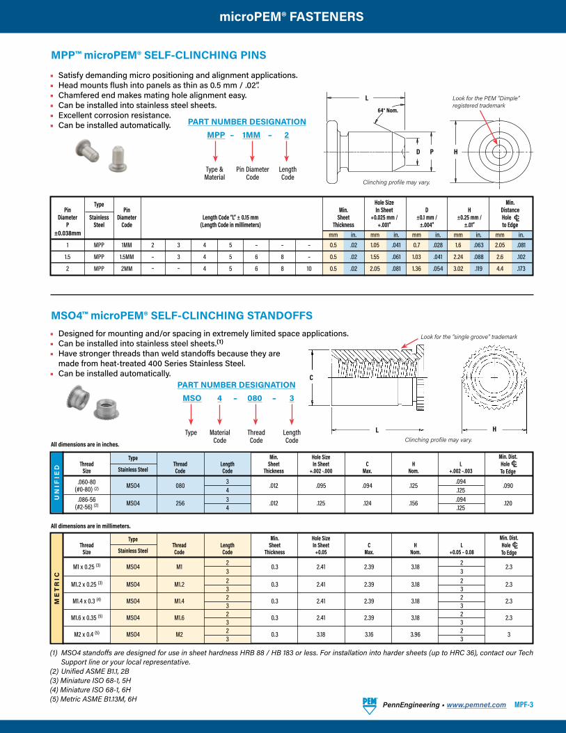
MPP™ microPEM® SELF-CLINCHING PINS
Type Hole Size Min. Pin Pin
Min. In Sheet D H Distance Diameter Stainless Diameter Length Code “L” ± 0.15 mm Sheet +0.025 mm / ±0.1 mm / ±0.25 mm / HoleC/L
P Steel Code (Length Code in millimeters) Thickness +.001” ±.004” ±.01” to Edge ±0.038mm mm in. mm in. mm in. mm in. mm in. 1 MPP 1MM 2 3 4 5 – – – 0.5 .02 1.05 .041 0.7 .028 1.6 .063 2.05 .081
1.5 MPP 1.5MM – 3 4 5 6 8 – 0.5 .02 1.55 .061 1.03 .041 2.24 .088 2.6 .102
2 MPP 2MM – – 4 5 6 8 10 0.5 .02 2.05 .081 1.36 .054 3.02 .119 4.4 .173
• Satisfy demanding micro positioning and alignment applications.• Head mounts flush into panels as thin as 0.5 mm / .02”.• Chamfered end makes mating hole alignment easy.• Can be installed into stainless steel sheets.• Excellent corrosion resistance.• Can be installed automatically.
MPP – 1MM – 2PART NUMBER DESIGNATION
Type & Material
Pin Diameter Code
Length Code
UN
IFIE
D
Type Min. Hole Size Min. Dist. Thread Thread Length Sheet In Sheet C H L Hole C/ Size Stainless Steel Code Code Thickness +.002 -.000 Max. Nom. +.002 –.003 To Edge
.060-80 MSO4 080 3 .012 .095 .094 .125 .094 .090 (#0-80) (2) 4 .125 .086-56 MSO4 256 3 .012 .125 .124 .156 .094 .120 (#2-56) (2) 4 .125
All dimensions are in inches.
All dimensions are in millimeters.
ME
TR
IC
Type Min. Hole Size Min. Dist. Thread Thread Length Sheet In Sheet C H L Hole C/ Size Stainless Steel Code Code Thickness +0.05 Max. Nom. +0.05 – 0.08 To Edge
M1 x 0.25 (3) MSO4 M1 2 0.3 2.41 2.39 3.18 2 2.3 3 3
M1.2 x 0.25 (3) MSO4 M1.2 2 0.3 2.41 2.39 3.18 2 2.3 3 3 M1.4 x 0.3 (4) MSO4 M1.4 2 0.3 2.41 2.39 3.18 2 2.3 3 3 M1.6 x 0.35 (5) MSO4 M1.6 2 0.3 2.41 2.39 3.18 2 2.3 3 3 M2 x 0.4 (5) MSO4 M2 2 0.3 3.18 3.16 3.96 2 3 3 3
MSO4™ microPEM® SELF-CLINCHING STANDOFFS
(1) MSO4 standoffs are designed for use in sheet hardness HRB 88 / HB 183 or less. For installation into harder sheets (up to HRC 36), contact our Tech Support line or your local representative.
(2) Unified ASME B1.1, 2B(3) Miniature ISO 68-1, 5H(4) Miniature ISO 68-1, 6H(5) Metric ASME B1.13M, 6H
MSO 4 – 080 – 3PART NUMBER DESIGNATION
Type Thread Code
Length Code
MaterialCode
• Designed for mounting and/or spacing in extremely limited space applications.• Can be installed into stainless steel sheets.(1)
• Have stronger threads than weld standoffs because they are made from heat-treated 400 Series Stainless Steel.• Can be installed automatically.
H
L
64° Nom.
PD
Look for the PEM “Dimple” registered trademark
Clinching profile may vary.
HL
C
Look for the “single groove” trademark
Clinching profile may vary.
MPF-4 PennEngineering • www.pemnet.com
microPEM® FASTENERS
Type Base Top Base Top Sheet Base Panel Min. Panel Sheet Top Panel Hole Size Hole Size A B C H P T Dist. Stain- Hole Thick- Sheet Min. Sheet ±0.05 mm / -0.05 mm / ±0.025 mm / ±0.075 mm / Max. ±0.1 mm / ±0.05 mm / ±0.1 mm / Hole CL Alumi- less Size ness Thickness Thickness (1) ±.002” -.002” ±.001” ±.003” ±.004” ±.002” ±.004” To Edge num Steel Code Code mm in. mm in. mm in. mm in. mm in. mm in. mm in. mm in. mm in. mm in. mm in. TA T4 10 025 0.2-0.28 .008-.011 0.89 .035 1.47 .058 1.02 .040 0.406 .016 0.610 .024 0.89 .035 2 .079 1.3 .051 0.2 .008 1 .039
TA T4 10 050 0.48-0.56 .019-.022 0.89 .035 1.47 .058 1.02 .040 0.686 .027 0.610 .024 0.89 .035 2 .079 1.3 .051 0.2 .008 1 .039
TA – 10 075 0.71-0.79 .028-.031 0.89 .035 1.47 .058 1.02 .040 0.914 .036 0.610 .024 0.89 .035 2 .079 1.3 .051 0.2 .008 1 .039
(1) 0.89 mm / .035” for blind holes and 0.5 mm / .020” for through holes.
Base panel.TackPin fastener installs into blind or through hole applications.
TopsheetTA – 10 – 025
T4 – 10 – 025
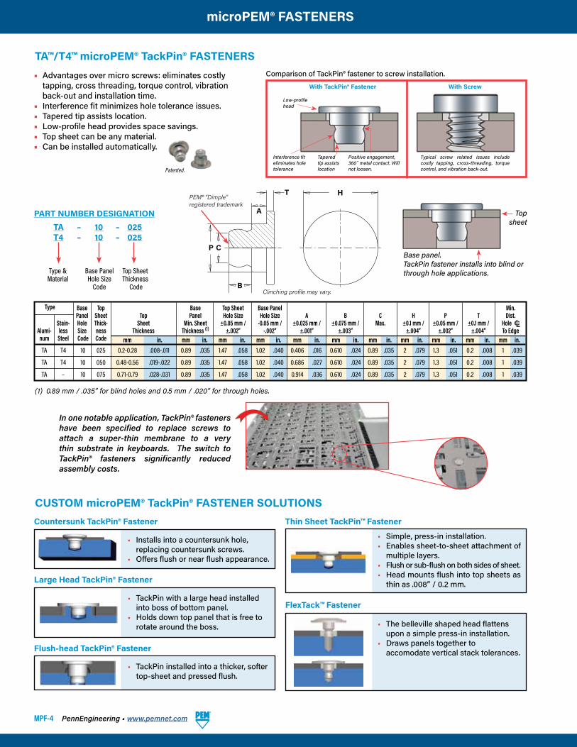
PART NUMBER DESIGNATION
Type & Material
Base PanelHole Size
Code
Top SheetThickness
Code
• Advantages over micro screws: eliminates costly tapping, cross threading, torque control, vibration back-out and installation time.
• Interference fit minimizes hole tolerance issues.• Tapered tip assists location.• Low-profile head provides space savings.• Top sheet can be any material.• Can be installed automatically.
TA™/T4™ microPEM® TackPin® FASTENERS
Interference fiteliminates holetolerance
Tapered tip assists location
Positive engagement, 360˚ metal contact. Will not loosen.
Low-profile head
With TackPin® Fastener With Screw
Typical screw related issues include costly tapping, cross-threading, torque control, and vibration back-out.
Comparison of TackPin® fastener to screw installation.
Patented.
In one notable application, TackPin® fasteners have been specified to replace screws to attach a super-thin membrane to a very thin substrate in keyboards. The switch to TackPin® fasteners significantly reduced assembly costs.
Thin Sheet TackPin™ FastenerCountersunk TackPin® Fastener
CUSTOM microPEM® TackPin® FASTENER SOLUTIONS
• Installs into a countersunk hole, replacing countersunk screws.
• Offers flush or near flush appearance.
• Simple, press-in installation.• Enables sheet-to-sheet attachment of
multiple layers.• Flush or sub-flush on both sides of sheet.• Head mounts flush into top sheets as
thin as .008” / 0.2 mm.
H
B
P C
T
A
PEM® “Dimple”registered trademark
Clinching profile may vary.
• TackPin with a large head installed into boss of bottom panel.
• Holds down top panel that is free to rotate around the boss.
Large Head TackPin® Fastener
• TackPin installed into a thicker, softer top-sheet and pressed flush.
Flush-head TackPin® Fastener
FlexTack™ Fastener
• The belleville shaped head flattens upon a simple press-in installation.
• Draws panels together to accomodate vertical stack tolerances.
PennEngineering • www.pemnet.com MPF-5
microPEM® FASTENERS
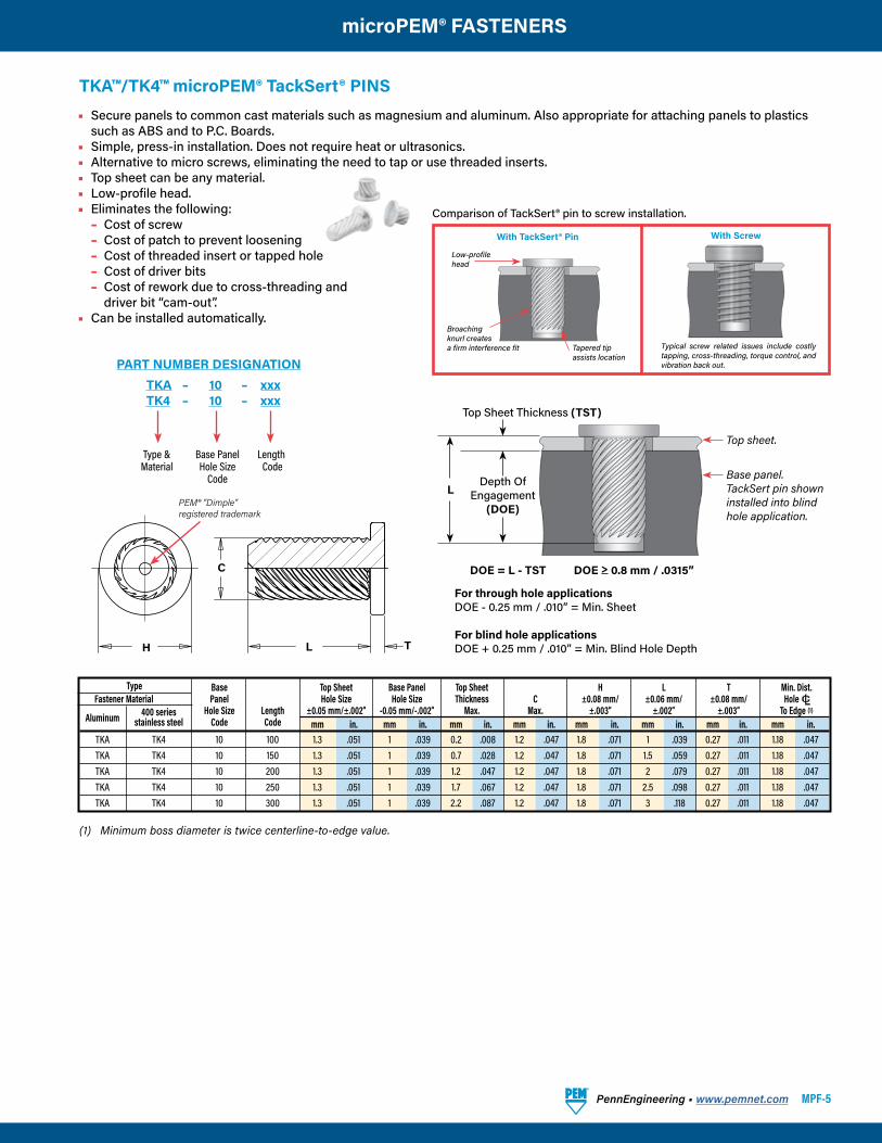
TKA™/TK4™ microPEM® TackSert® PINS• Secure panels to common cast materials such as magnesium and aluminum. Also appropriate for attaching panels to plastics
such as ABS and to P.C. Boards.• Simple, press-in installation. Does not require heat or ultrasonics.• Alternative to micro screws, eliminating the need to tap or use threaded inserts.• Top sheet can be any material.• Low-profile head.• Eliminates the following: – Cost of screw – Cost of patch to prevent loosening – Cost of threaded insert or tapped hole – Cost of driver bits – Cost of rework due to cross-threading and driver bit “cam-out”.• Can be installed automatically.
TKA – 10 – xxxTK4 – 10 – xxx
PART NUMBER DESIGNATION
Type & Material
Base PanelHole Size
Code
Length Code
Type Base Top Sheet Base Panel Top Sheet H L T Min. Dist. Fastener Material Panel Hole Size Hole Size Thickness C ±0.08 mm/ ±0.06 mm/ ±0.08 mm/ Hole CL
Aluminum 400 series Hole Size Length ±0.05 mm/±.002” -0.05 mm/-.002” Max. Max. ±.003” ±.002” ±.003” To Edge (1)
stainless steel Code Code mm in. mm in. mm in. mm in. mm in. mm in. mm in. mm in. TKA TK4 10 100 1.3 .051 1 .039 0.2 .008 1.2 .047 1.8 .071 1 .039 0.27 .011 1.18 .047 TKA TK4 10 150 1.3 .051 1 .039 0.7 .028 1.2 .047 1.8 .071 1.5 .059 0.27 .011 1.18 .047 TKA TK4 10 200 1.3 .051 1 .039 1.2 .047 1.2 .047 1.8 .071 2 .079 0.27 .011 1.18 .047 TKA TK4 10 250 1.3 .051 1 .039 1.7 .067 1.2 .047 1.8 .071 2.5 .098 0.27 .011 1.18 .047 TKA TK4 10 300 1.3 .051 1 .039 2.2 .087 1.2 .047 1.8 .071 3 .118 0.27 .011 1.18 .047
(1) Minimum boss diameter is twice centerline-to-edge value.
For through hole applicationsDOE - 0.25 mm / .010” = Min. Sheet
For blind hole applicationsDOE + 0.25 mm / .010” = Min. Blind Hole Depth
Base panel.TackSert pin showninstalled into blindhole application.
Top sheet.
Top Sheet Thickness (TST)
Depth OfEngagement
(DOE)
DOE = L - TST DOE > 0.8 mm / .0315”
L
Broachingknurl createsa firm interference fit Tapered tip
assists location
Low-profile head
With TackSert® Pin With Screw
Typical screw related issues include costly tapping, cross-threading, torque control, and vibration back out.
Comparison of TackSert® pin to screw installation.
H
C
TL
PEM® “Dimple”registered trademark
MPF-6 PennEngineering • www.pemnet.com
microPEM® FASTENERS
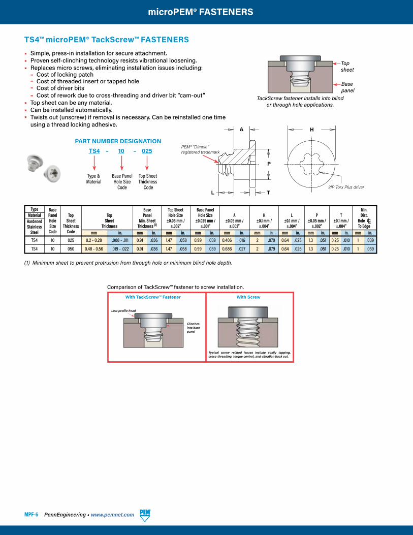
Type Base Base Top Sheet Base Panel Min. Material Panel Top Top Panel Hole Size Hole Size A H L P T Dist. Hardened Hole Sheet Sheet Min. Sheet ±0.05 mm / ±0.025 mm / ±0.05 mm / ±0.1 mm / ±0.1 mm / ±0.05 mm / ±0.1 mm / Hole CL Stainless Size Thickness Thickness Thickness (1) ±.002” ±.001” ±.002” ±.004” ±.004” ±.002” ±.004” To Edge Steel Code Code mm in. mm in. mm in. mm in. mm in. mm in. mm in. mm in. mm in. mm in. TS4 10 025 0.2 - 0.28 .008 - .011 0.91 .036 1.47 .058 0.99 .039 0.406 .016 2 .079 0.64 .025 1.3 .051 0.25 .010 1 .039
TS4 10 050 0.48 - 0.56 .019 - .022 0.91 .036 1.47 .058 0.99 .039 0.686 .027 2 .079 0.64 .025 1.3 .051 0.25 .010 1 .039
TackScrew fastener installs into blind or through hole applications.
Topsheet
Base panel
(1) Minimum sheet to prevent protrusion from through hole or minimum blind hole depth.
TS4™ microPEM® TackScrew™ FASTENERS• Simple, press-in installation for secure attachment.• Proven self-clinching technology resists vibrational loosening.• Replaces micro screws, eliminating installation issues including: – Cost of locking patch – Cost of threaded insert or tapped hole – Cost of driver bits – Cost of rework due to cross-threading and driver bit “cam-out”• Top sheet can be any material.• Can be installed automatically.• Twists out (unscrew) if removal is necessary. Can be reinstalled one time
using a thread locking adhesive.
TS4 – 10 – 025PART NUMBER DESIGNATION
Type & Material
Base PanelHole Size
Code
Top SheetThickness
Code
With TackScrew™ Fastener With Screw
Comparison of TackScrew™ fastener to screw installation.
Low-profile head
Typical screw related issues include costly tapping, cross-threading, torque control, and vibration back out.
Clinches into base panel
HA
P
L2IP Torx Plus driver
T
PEM® “Dimple”registered trademark
PennEngineering • www.pemnet.com MPF-7
microPEM® FASTENERS
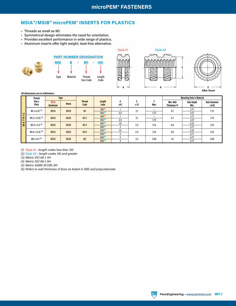
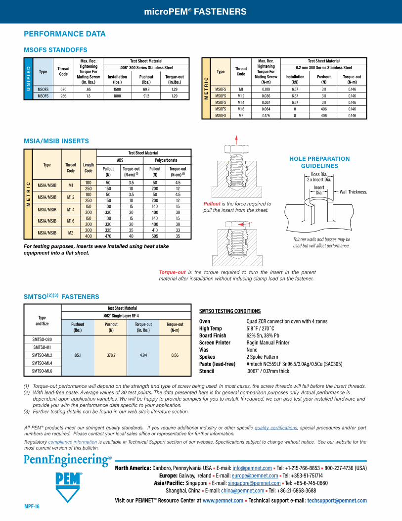
MSIA™/MSIB™ microPEM® INSERTS FOR PLASTICS
• Threads as small as M1.• Symmetrical design eliminates the need for orientation.• Provides excellent performance in wide range of plastics.• Aluminum inserts offer light weight, lead-free alternative.
(1) Style #1 - length codes less than 150(2) Style #2 - length codes 150 and greater(3) Metric ISO 68-1, 5H(4) Metric ISO 68-1, 6H(5) Metric ASME B1.13M, 6H(6) Refers to wall thickness of boss as tested in ABS and polycarbonate.
Style #1 Style #2
A
C
EAAfter Knurl
MSI B – M1 – 100PART NUMBER DESIGNATION
Type ThreadSize Code
LengthCode
Material
All dimensions are in millimeters.
ME
TR
IC
Thread Type Size x New
Brass Thread Length A E C Min. Wall Hole Depth Hole Diameter
Pitch Aluminum Code Code ±0.1 ± 0.1 Max. Thickness (6) Min. +0.05
M1 x 0.25 (3) MSIA MSIB M1 100(1) 1 2.1 — 0.7 1.77 1.75 250(2) 2.5 1.75 3.27
M1.2 x 0.25 (3) MSIA MSIB M1.2 100(1) 1 2.1 — 0.7 1.77 1.75 250(2) 2.5 1.75 3.27
M1.4 x 0.3 (4) MSIA MSIB M1.4 150(2) 1.5 2.5 2.15 0.8 2.27 2.15 300(2) 3 3.77
M1.6 x 0.35 (5) MSIA MSIB M1.6 150(2) 1.5 2.5 2.15 0.8 2.27 2.15 300(2) 3 3.77
M2 x 0.4 (5) MSIA MSIB M2 300(2) 3 3.2 2.85 1.6 3.77 2.85 400(2) 4 4.77
Mounting Hole in Material
MPF-8 PennEngineering • www.pemnet.com
microPEM® FASTENERS
NEW!U
NIF
IED
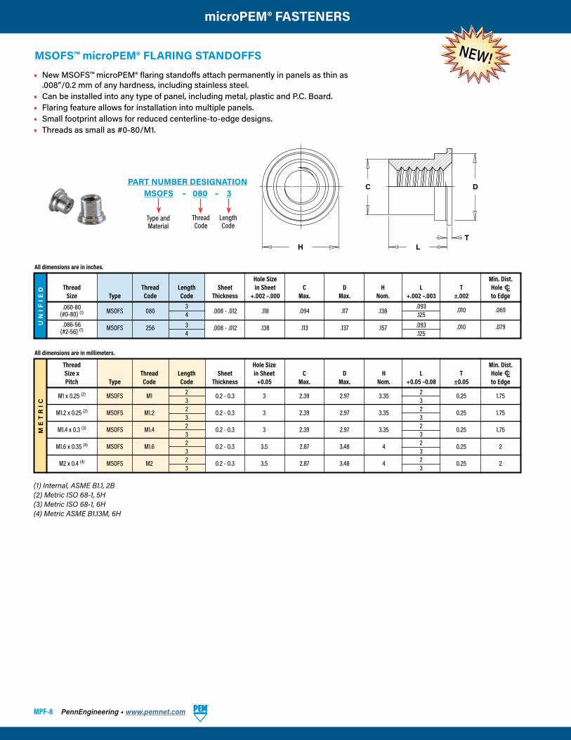
Hole Size Min. Dist. Thread Thread Length Sheet in Sheet C D H L T Hole CL Size Type Code Code Thickness +.002 –.000 Max. Max. Nom. +.002 –.003 ±.002 to Edge .060-80
MSOFS 080 3
.008 - .012 .118 .094 .117 .138 .093 .010 .069
(#0-80) (1) 4 .125 .086-56
MSOFS 256 3 .008 - .012 .138 .113 .137 .157 .093 .010 .079
(#2-56) (1) 4 .125
All dimensions are in inches.
ME
TR
IC
Thread Hole Size Min. Dist. Size x Thread Length Sheet in Sheet C D H L T Hole CL Pitch Type Code Code Thickness +0.05 Max. Max. Nom. +0.05 –0.08 ±0.05 to Edge M1 x 0.25 (2) MSOFS M1 2 0.2 - 0.3 3 2.39 2.97 3.35 2 0.25 1.75 3 3 M1.2 x 0.25 (2) MSOFS M1.2 2 0.2 - 0.3 3 2.39 2.97 3.35 2 0.25 1.75 3 3 M1.4 x 0.3 (3) MSOFS M1.4 2 0.2 - 0.3 3 2.39 2.97 3.35 2 0.25 1.75 3 3 M1.6 x 0.35 (4) MSOFS M1.6 2 0.2 - 0.3 3.5 2.87 3.48 4 2 0.25 2 3 3 M2 x 0.4 (4) MSOFS M2 2 0.2 - 0.3 3.5 2.87 3.48 4 2 0.25 2 3 3
All dimensions are in millimeters.
H
C
TL
D
• New MSOFS™ microPEM® flaring standoffs attach permanently in panels as thin as .008”/0.2 mm of any hardness, including stainless steel.
• Can be installed into any type of panel, including metal, plastic and P.C. Board.• Flaring feature allows for installation into multiple panels.• Small footprint allows for reduced centerline-to-edge designs.• Threads as small as #0-80/M1.
MSOFS – 080 – 3PART NUMBER DESIGNATION
ThreadCode
LengthCode
Type andMaterial
MSOFS™ microPEM® FLARING STANDOFFS
(1) Internal, ASME B1.1, 2B(2) Metric ISO 68-1, 5H(3) Metric ISO 68-1, 6H(4) Metric ASME B1.13M, 6H
PennEngineering • www.pemnet.com MPF-9
microPEM® FASTENERS
UN
IFIE
D
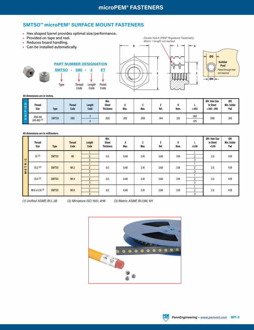
Min. ØH Hole Size ØD Thread Thread Length Sheet A C E H L In Sheet Min. Solder Size Type Code Code Thickness Max. Max. Ref. Nom. ±.003 +.003 –.000 Pad
.060-80 SMTSO 080
2 .020 .019 .095 .144 .125
.062 .098 .165
(#0-80) (1) 4 .125
All dimensions are in inches.
ME
TR
IC
Min. ØH Hole Size ØD Thread Thread Length Sheet A C E H L In Sheet Min. Solder Size Type Code Code Thickness Max. Max. Ref. Nom. ±0.08 +0.08 Pad
1 1 S1 (2) SMTSO M1 2 0.5 0.48 2.41 3.66 3.18 2 2.5 4.19 3 3 1 1 S1.2 (2) SMTSO M1.2 2 0.5 0.48 2.41 3.66 3.18 2 2.5 4.19 3 3 1 1 S1.4 (2) SMTSO M1.4 2 0.5 0.48 2.41 3.66 3.18 2 2.5 4.19 3 3 1 1 M1.6 x 0.35 (3) SMTSO M1.6 2 0.5 0.48 2.41 3.66 3.18 2 2.5 4.19 3 3
All dimensions are in millimeters.
• Hex shaped barrel provides optimal size/performance.• Provided on tape and reel.• Reduces board handling.• Can be installed automatically.
ØH
ØD
SolderPad
Plated through hole not required.E
H
C
AL
Double Notch (PEM® Registered Trademark)Metric -1 length not marked
SMTSO™ microPEM® SURFACE MOUNT FASTENERS
SMTSO – 080 – 2 ETPART NUMBER DESIGNATION
Type Length Code
FinishCode
ThreadCode
(1) Unified ASME B1.1, 2B (2) Miniature ISO 1501, 4H6 (3) Metric ASME B1.13M, 6H
MPF-10 PennEngineering • www.pemnet.com
microPEM® FASTENERS
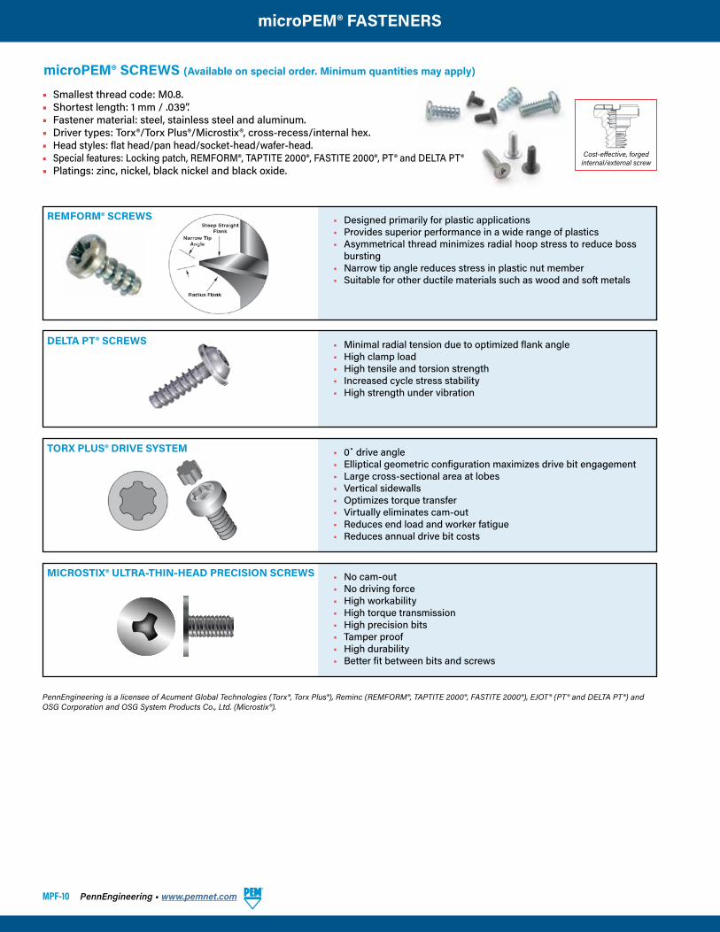
microPEM® SCREWS (Available on special order. Minimum quantities may apply)
• Smallest thread code: M0.8. • Shortest length: 1 mm / .039”.• Fastener material: steel, stainless steel and aluminum.• Driver types: Torx®/Torx Plus®/Microstix®, cross-recess/internal hex.• Head styles: flat head/pan head/socket-head/wafer-head.• Special features: Locking patch, REMFORM®, TAPTITE 2000®, FASTITE 2000®, PT® and DELTA PT®• Platings: zinc, nickel, black nickel and black oxide.
PennEngineering is a licensee of Acument Global Technologies (Torx®, Torx Plus®), Reminc (REMFORM®, TAPTITE 2000®, FASTITE 2000®), EJOT® (PT® and DELTA PT®) and OSG Corporation and OSG System Products Co., Ltd. (Microstix®).
TORX PLUS® DRIVE SYSTEM
• Designed primarily for plastic applications• Provides superior performance in a wide range of plastics• Asymmetrical thread minimizes radial hoop stress to reduce boss
bursting• Narrow tip angle reduces stress in plastic nut member• Suitable for other ductile materials such as wood and soft metals
REMFORM® SCREWS
• 0˚ drive angle• Elliptical geometric configuration maximizes drive bit engagement• Large cross-sectional area at lobes• Vertical sidewalls• Optimizes torque transfer• Virtually eliminates cam-out• Reduces end load and worker fatigue• Reduces annual drive bit costs
• Minimal radial tension due to optimized flank angle• High clamp load• High tensile and torsion strength• Increased cycle stress stability• High strength under vibration
DELTA PT® SCREWS
Cost-effective, forged internal/external screw
• No cam-out• No driving force• High workability• High torque transmission• High precision bits• Tamper proof• High durability• Better fit between bits and screws
MICROSTIX® ULTRA-THIN-HEAD PRECISION SCREWS
PennEngineering • www.pemnet.com MPF-11
microPEM® FASTENERS
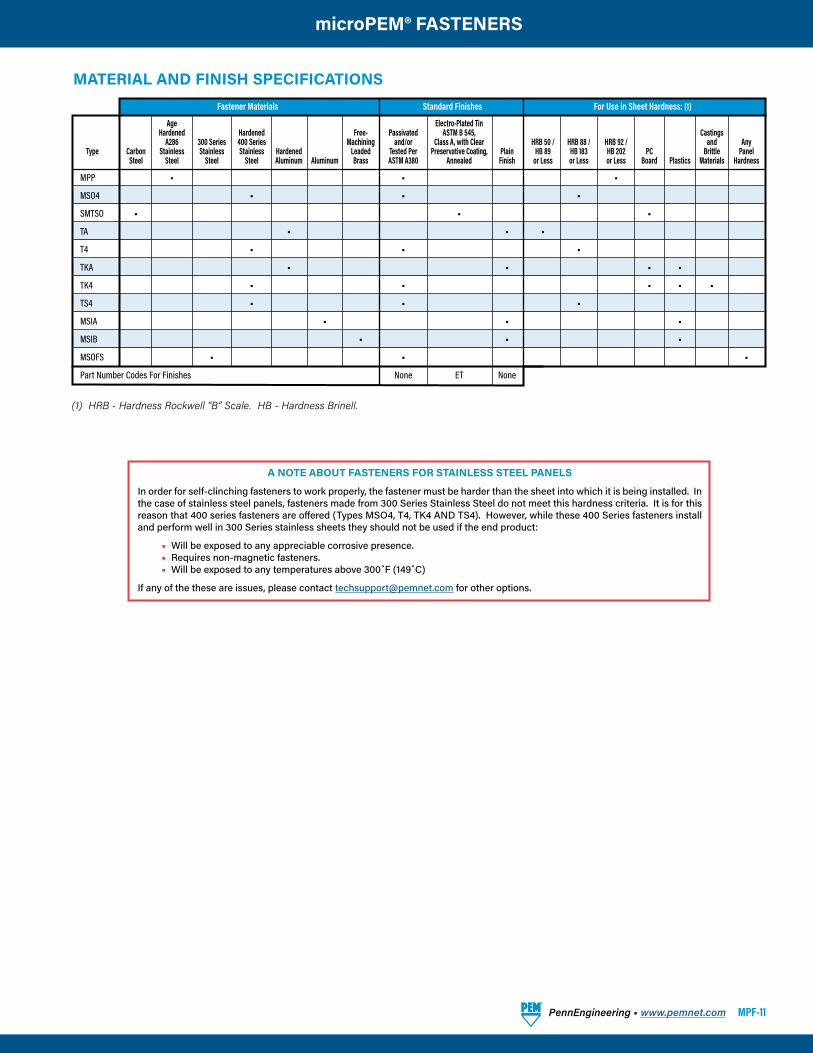
MATERIAL AND FINISH SPECIFICATIONS
(1) HRB - Hardness Rockwell “B” Scale. HB - Hardness Brinell.
Fastener Materials Standard Finishes For Use in Sheet Hardness: (1)
Age Electro-Plated Tin Hardened Hardened Free- Passivated ASTM B 545, Castings A286 300 Series 400 Series Machining and/or Class A, with Clear HRB 50 / HRB 88 / HRB 92 / and Any Type Carbon Stainless Stainless Stainless Hardened Leaded Tested Per Preservative Coating, Plain HB 89 HB 183 HB 202 PC Brittle Panel Steel Steel Steel Steel Aluminum Aluminum Brass ASTM A380 Annealed Finish or Less or Less or Less Board Plastics Materials Hardness
MPP • • •
MSO4 • • •
SMTSO • • •
TA • • •
T4 • • •
TKA • • • •
TK4 • • • • •
TS4 • • •
MSIA • • •
MSIB • • •
MSOFS • • •
Part Number Codes For Finishes None ET None
A NOTE ABOUT FASTENERS FOR STAINLESS STEEL PANELS
In order for self-clinching fasteners to work properly, the fastener must be harder than the sheet into which it is being installed. In the case of stainless steel panels, fasteners made from 300 Series Stainless Steel do not meet this hardness criteria. It is for this reason that 400 series fasteners are offered (Types MSO4, T4, TK4 AND TS4). However, while these 400 Series fasteners install and perform well in 300 Series stainless sheets they should not be used if the end product:
• Will be exposed to any appreciable corrosive presence. • Requires non-magnetic fasteners. • Will be exposed to any temperatures above 300˚F (149˚C)
If any of the these are issues, please contact [email protected] for other options.
MPF-12 PennEngineering • www.pemnet.com
microPEM® FASTENERS
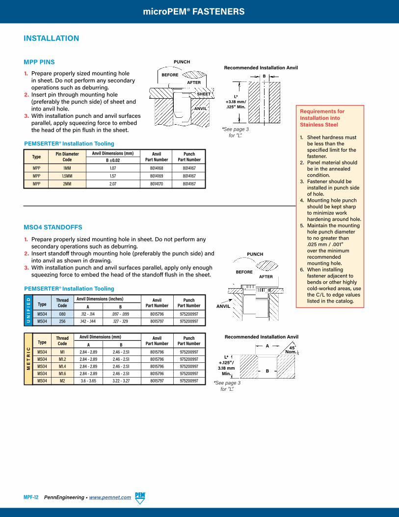
MSO4 STANDOFFS
PUNCH
ANVIL
BEFOREAFTER
UN
IFIE
D Thread Anvil Dimensions (inches) Anvil Punch Type Code A B Part Number Part Number
MSO4 080 .112 - .114 .097 - .099 8015796 975200997 MSO4 256 .142 - .144 .127 - .129 8015797 975200997
ME
TR
IC
Thread Anvil Dimensions (mm) Anvil Punch Type Code A B Part Number Part Number
MSO4 M1 2.84 - 2.89 2.46 - 2.51 8015796 975200997 MSO4 M1.2 2.84 - 2.89 2.46 - 2.51 8015796 975200997 MSO4 M1.4 2.84 - 2.89 2.46 - 2.51 8015796 975200997 MSO4 M1.6 2.84 - 2.89 2.46 - 2.51 8015796 975200997 MSO4 M2 3.6 - 3.65 3.22 - 3.27 8015797 975200997
1. Prepare properly sized mounting hole in sheet. Do not perform any secondary operations such as deburring.
2. Insert pin through mounting hole (preferably the punch side) of sheet and into anvil hole.
3. With installation punch and anvil surfaces parallel, apply squeezing force to embed the head of the pin flush in the sheet.
Type Pin Diameter Anvil Dimensions (mm) Anvil Punch Code B ±0.02 Part Number Part Number
MPP 1MM 1.07 8014168 8014167
MPP 1.5MM 1.57 8014169 8014167
MPP 2MM 2.07 8014170 8014167
MPP PINS
INSTALLATION
1. Prepare properly sized mounting hole in sheet. Do not perform any secondary operations such as deburring.
2. Insert standoff through mounting hole (preferably the punch side) and into anvil as shown in drawing.
3. With installation punch and anvil surfaces parallel, apply only enough squeezing force to embed the head of the standoff flush in the sheet.
B
L*+3.18 mm/.125” Min.
Recommended Installation Anvil
SHEET
ANVIL
PUNCH
BEFORE
AFTER
Requirements forInstallation intoStainless Steel
1. Sheet hardness must be less than the specified limit for the fastener.
2. Panel material should be in the annealed condition.
3. Fastener should be installed in punch side of hole.
4. Mounting hole punch should be kept sharp to minimize work hardening around hole.
5. Maintain the mounting hole punch diameter to no greater than .025 mm / .001” over the minimum recommended mounting hole.
6. When installing fastener adjacent to bends or other highly cold-worked areas, use the C/L to edge values listed in the catalog.
Recommended Installation Anvil
A
B
45˚Nom.
L*+.125”/3.18 mm
Min.
*See page 3for “L”.
*See page 3for “L”.
PEMSERTER® Installation Tooling
PEMSERTER® Installation Tooling
PennEngineering • www.pemnet.com MPF-13
microPEM® FASTENERS
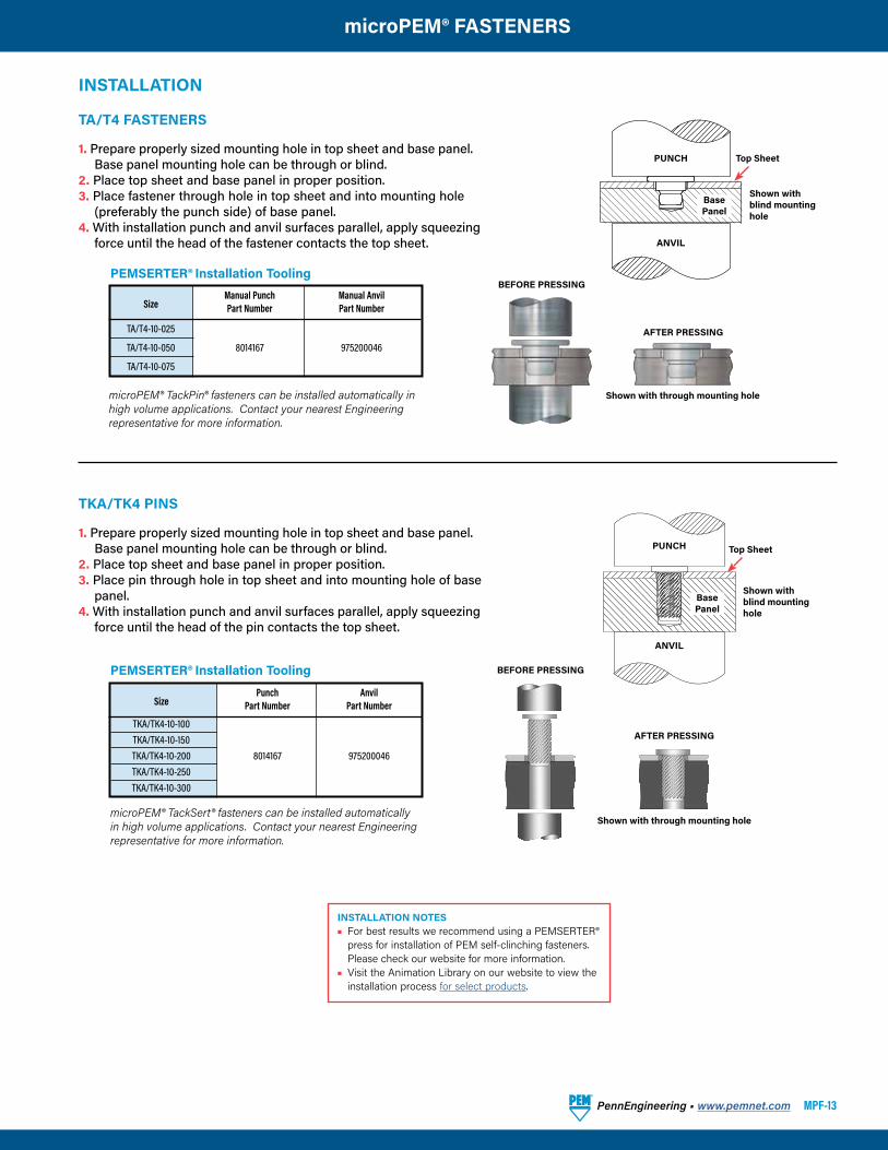
TA/T4 FASTENERS
Size
Manual Punch Manual Anvil Part Number Part Number
TA/T4-10-025
TA/T4-10-050 8014167 975200046
TA/T4-10-075
1. Prepare properly sized mounting hole in top sheet and base panel. Base panel mounting hole can be through or blind.
2. Place top sheet and base panel in proper position.3. Place fastener through hole in top sheet and into mounting hole
(preferably the punch side) of base panel.4. With installation punch and anvil surfaces parallel, apply squeezing
force until the head of the fastener contacts the top sheet.
microPEM® TackPin® fasteners can be installed automatically in high volume applications. Contact your nearest Engineering representative for more information.
BEFORE PRESSING
AFTER PRESSING
Shown with through mounting hole
PUNCH
ANVIL
Top Sheet
Shown with blind mounting hole
Base Panel
INSTALLATION
Size
Punch Anvil Part Number Part Number
TKA/TK4-10-100 TKA/TK4-10-150 TKA/TK4-10-200 8014167 975200046 TKA/TK4-10-250 TKA/TK4-10-300
BEFORE PRESSING
AFTER PRESSING
Shown with through mounting hole
TKA/TK4 PINS
1. Prepare properly sized mounting hole in top sheet and base panel. Base panel mounting hole can be through or blind.
2. Place top sheet and base panel in proper position.3. Place pin through hole in top sheet and into mounting hole of base
panel.4. With installation punch and anvil surfaces parallel, apply squeezing
force until the head of the pin contacts the top sheet.
PEMSERTER® Installation Tooling
PEMSERTER® Installation Tooling
microPEM® TackSert® fasteners can be installed automatically in high volume applications. Contact your nearest Engineering representative for more information.
PUNCH
ANVIL
Top Sheet
Base Panel
Shown with blind mounting hole
INSTALLATION NOTES• For best results we recommend using a PEMSERTER®
press for installation of PEM self-clinching fasteners. Please check our website for more information.
• Visit the Animation Library on our website to view the installation process for select products.
MPF-14 PennEngineering • www.pemnet.com
microPEM® FASTENERS
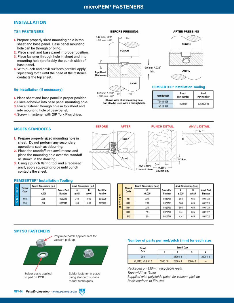
SMTSO FASTENERS
Solder paste applied to pad on PCB.
Solder fastener in place using standard surface mount techniques.
Polyimide patch applied here for vacuum pick up.
Thread Length Code
Code 1 2 3 4
080 — 3500 / 8 — 2000 / 8
M1, M1.2, M1.4, M1.6 3500 / 8 2500 / 8 2000 / 8 —
Number of parts per reel/pitch (mm) for each size
Packaged on 330mm recyclable reels.Tape width is 16mm.Supplied with polyimide patch for vacuum pick up.Reels conform to EIA-481.
TS4 FASTENERS
1. Prepare properly sized mounting hole in top sheet and base panel. Base panel mounting hole can be through or blind.
2. Place sheet and base panel in proper position.3. Place fastener through hole in sheet and into
mounting hole (preferably the punch side) of base panel.
4. With punch and anvil surfaces parallel, apply squeezing force until the head of the fastener contacts the top sheet.
Re-installation (if necessary)
1. Place sheet and base panel in proper position.2. Place adhesive into base panel mounting hole.3. Place fastener through hole in top sheet and
into mounting hole of base panel.4. Screw in fastener with 2IP Torx Plus driver.
PEMSERTER® Installation Tooling
Part Number
Punch Anvil Part Number Part Number
TS4-10-025 8014167 975200046
TS4-10-050
INSTALLATION
BEFORE PRESSING
PUNCH
ANVIL
Shown with blind mounting hole.Can also be used with a through hole.
1.47 mm / .058”± 0.05 mm / ± .002”
0.91 mm / .036”Min.
0.99 mm / .039”± 0.025 mm / ± .001”
Top Sheet Thickness
AFTER PRESSING
PUNCH
ANVIL
UN
IFIE
D
PEMSERTER® Installation Tooling
MSOFS STANDOFFS
1. Prepare properly sized mounting hole in sheet. Do not perform any secondary operations such as deburring.
2. Place the standoff into anvil recess and place the mounting hole over the standoff as shown in the drawing.
3. Using a punch flaring tool and a recessed anvil, apply squeezing force until punch contacts the sheet.
Thread Punch Dimensions (in.) Anvil Dimensions (in.)
Code C Punch Part A B Anvil Part +.001 Number ±.001 ±.001 Number
080 .095 8020712 .143 .006 8019720
256 .114 8020710 .163 .006 8019722
ME
TR
IC
Thread Punch Dimensions (mm) Anvil Dimensions (mm)
Code C Punch Part A B Anvil Part +0.025 Number ±.025 ±.025 Number
M1 2.41 8020712 3.64 0.15 8019720
M1.2 2.41 8020712 3.64 0.15 8019720
M1.4 2.41 8020712 3.64 0.15 8019720
M1.6 2.9 8020710 4.14 0.15 8019722
M2 2.9 8020710 4.14 0.15 8019722
BEFORE AFTER PUNCH DETAIL ANVIL DETAILA
BPunch
Anvil
CØ .250”/
6.35 mm Min.
15˚ Nom.
.004” ±.001”/0.1 mm ±0.25 mm
PennEngineering • www.pemnet.com MPF-15
microPEM® FASTENERS
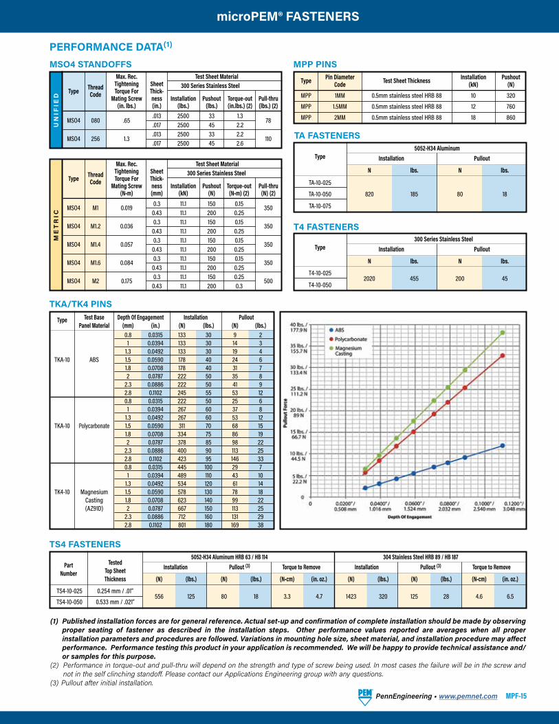
5052-H34 Aluminum HRB 63 / HB 114 304 Stainless Steel HRB 89 / HB 187 Part Tested Installation Pullout (3) Torque to Remove Installation Pullout (3) Torque to Remove Number Top Sheet
Thickness (N) (lbs.) (N) (lbs.) (N•cm) (in. oz.) (N) (lbs.) (N) (lbs.) (N•cm) (in. oz.)
TS4-10-025 0.254 mm / .01” 556 125 80 18 3.3 4.7 1423 320 125 28 4.6 6.5
TS4-10-050 0.533 mm / .021”
TS4 FASTENERS
ME
TR
ICPERFORMANCE DATA(1)
Type Pin Diameter Test Sheet Thickness Installation Pushout Code (kN) (N)
MPP 1MM 0.5mm stainless steel HRB 88 10 320
MPP 1.5MM 0.5mm stainless steel HRB 88 12 760
MPP 2MM 0.5mm stainless steel HRB 88 18 860
(1) Published installation forces are for general reference. Actual set-up and confirmation of complete installation should be made by observing proper seating of fastener as described in the installation steps. Other performance values reported are averages when all proper installation parameters and procedures are followed. Variations in mounting hole size, sheet material, and installation procedure may affect performance. Performance testing this product in your application is recommended. We will be happy to provide technical assistance and/or samples for this purpose.
(2) Performance in torque-out and pull-thru will depend on the strength and type of screw being used. In most cases the failure will be in the screw and not in the self clinching standoff. Please contact our Applications Engineering group with any questions.
(3) Pullout after initial installation.
UN
IFIE
D
Max. Rec. Test Sheet Material Thread Tightening Sheet 300 Series Stainless Steel Type Code Torque For Thick- Mating Screw ness Installation Pushout Torque-out Pull-thru (in. lbs.) (in.) (lbs.) (lbs.) (in.lbs.) (2) (lbs.) (2)
MSO4 080 .65 .013 2500 33 1.3 78
.017 2500 45 2.2 MSO4 256 1.3 .013 2500 33 2.2
110 .017 2500 45 2.6
Max. Rec. Test Sheet Material Thread Tightening Sheet 300 Series Stainless Steel Type Code Torque For Thick- Mating Screw ness Installation Pushout Torque-out Pull-thru (N•m) (mm) (kN) (N) (N•m) (2) (N) (2)
MSO4 M1 0.019 0.3 11.1 150 0.15 350 0.43 11.1 200 0.25 MSO4 M1.2 0.036 0.3 11.1 150 0.15 350 0.43 11.1 200 0.25 MSO4 M1.4 0.057 0.3 11.1 150 0.15 350 0.43 11.1 200 0.25 MSO4 M1.6 0.084 0.3 11.1 150 0.15 350 0.43 11.1 200 0.25 MSO4 M2 0.175 0.3 11.1 150 0.25 500 0.43 11.1 200 0.3
MPP PINSMSO4 STANDOFFS
5052-H34 Aluminum Type Installation Pullout N lbs. N lbs.
TA-10-025
TA-10-050 820 185 80 18
TA-10-075
TA FASTENERS
Type Test Base Depth Of Engagement Installation Pullout Panel Material (mm) (in.) (N) (lbs.) (N) (lbs.) 0.8 0.0315 133 30 9 2 1 0.0394 133 30 14 3 1.3 0.0492 133 30 19 4 TKA-10 ABS 1.5 0.0590 178 40 24 6 1.8 0.0708 178 40 31 7 2 0.0787 222 50 35 8 2.3 0.0886 222 50 41 9 2.8 0.1102 245 55 53 12 0.8 0.0315 222 50 25 6 1 0.0394 267 60 37 8 1.3 0.0492 267 60 53 12 TKA-10 Polycarbonate 1.5 0.0590 311 70 68 15 1.8 0.0708 334 75 86 19 2 0.0787 378 85 98 22 2.3 0.0886 400 90 113 25 2.8 0.1102 423 95 146 33 0.8 0.0315 445 100 29 7 1 0.0394 489 110 43 10 1.3 0.0492 534 120 61 14 TK4-10 Magnesium 1.5 0.0590 578 130 78 18 Casting 1.8 0.0708 623 140 99 22 (AZ91D) 2 0.0787 667 150 113 25 2.3 0.0886 712 160 131 29 2.8 0.1102 801 180 169 38
TKA/TK4 PINS
300 Series Stainless Steel Type Installation Pullout N lbs. N lbs.
T4-10-025 2020 455 200 45
T4-10-050
T4 FASTENERS
MPF-16
All PEM® products meet our stringent quality standards. If you require additional industry or other specific quality certifications, special procedures and/or part numbers are required. Please contact your local sales office or representative for further information.
Regulatory compliance information is available in Technical Support section of our website. Specifications subject to change without notice. See our website for the most current version of this bulletin.
North America: Danboro, Pennsylvania USA • E-mail: [email protected] • Tel: +1-215-766-8853 • 800-237-4736 (USA)Europe: Galway, Ireland • E-mail: [email protected] • Tel: +353-91-751714
Asia/Pacific: Singapore • E-mail: [email protected] • Tel: +65-6-745-0660Shanghai, China • E-mail: [email protected] • Tel: +86-21-5868-3688
Visit our PEMNET™ Resource Center at www.pemnet.com • Technical support e-mail: [email protected]
microPEM® FASTENERS
SMTSO(2)(3) FASTENERS
SMTSO TESTING CONDITIONS
Oven Quad ZCR convection oven with 4 zonesHigh Temp 518˚F / 270˚CBoard Finish 62% Sn, 38% PbScreen Printer Ragin Manual PrinterVias NoneSpokes 2 Spoke PatternPaste (lead-free) Amtech NC559LF Sn96.5/3.0Ag/0.5Cu (SAC305)Stencil .0067” / 0.17mm thick
Test Sheet Material Type .062” Single Layer RF-4
and Size Pushout Pushout Torque-out Torque-out (lbs.) (N) (in. lbs.) (N•m)
SMTSO-080
SMTSO-M1
SMTSO-M1.2 85.1 378.7 4.94 0.56
SMTSO-M1.4
SMTSO-M1.6
(1) Torque-out performance will depend on the strength and type of screw being used. In most cases, the screw threads will fail before the insert threads.(2) With lead-free paste. Average values of 30 test points. The data presented here is for general comparison purposes only. Actual performance is
dependent upon application variables. We will be happy to provide samples for you to install. If required, we can also test your installed hardware and provide you with the performance data specific to your application.
(3) Further testing details can be found in our web site’s literature section.
ME
TR
IC
Type Thread Length Code Code Pullout Torque-out Pullout Torque-out
(N) (N•cm) (1) (N) (N•cm) (1)
MSIA/MSIB M1 100 50 3.5 50 4.5 250 150 10 200 12 MSIA/MSIB M1.2 100 50 3.5 50 4.5 250 150 10 200 12
MSIA/MSIB M1.4 150 100 15 140 15
300 330 30 400 30 MSIA/MSIB M1.6 150 100 15 140 15 300 330 30 400 30 MSIA/MSIB M2 300 335 35 410 33 400 470 40 595 35
Test Sheet Material ABS Polycarbonate
Pullout is the force required to pull the insert from the sheet.
Torque-out is the torque required to turn the insert in the parent material after installation without inducing clamp load on the fastener.
MSIA/MSIB INSERTS
For testing purposes, inserts were installed using heat stake equipment into a flat sheet.
HOLE PREPARATION GUIDELINES
Thinner walls and bosses may be used but will affect performance.
Wall Thickness.
Boss Dia.2 x Insert Dia.
InsertDia.
PERFORMANCE DATA
MSOFS STANDOFFS
UN
IFIE
D
Max. Rec. Test Sheet Material Thread Tightening .008” 300 Series Stainless Steel Type Code Torque For Mating Screw Installation Pushout Torque-out (in. lbs.) (lbs.) (lbs.) (in.lbs.) MSOFS 080 .65 1500 69.8 1.29 MSOFS 256 1.3 1800 91.2 1.29 M
ET
RIC
Max. Rec. Test Sheet Material Thread Tightening 0.2 mm 300 Series Stainless Steel Type Code Torque For Mating Screw Installation Pushout Torque-out (N•m) (kN) (N) (N•m)
MSOFS M1 0.019 6.67 311 0.146 MSOFS M1.2 0.036 6.67 311 0.146 MSOFS M1.4 0.057 6.67 311 0.146 MSOFS M1.6 0.084 8 406 0.146 MSOFS M2 0.175 8 406 0.146