
Pipe vibration measurements - Microsoft consultants) for the pipe vibration measurements at the four...
22
Transcript of Pipe vibration measurements - Microsoft consultants) for the pipe vibration measurements at the four...

Governance
Steering group consists of:
• Forsmark: Magnus Adolfsson and Ylva Vidhög
• Fortum: Heikki Haapaniemi and Jari Tenhunen
• OKG: Tobias Törnström(chairman), Carl Möller and Kent Andersson
• Ringhals: Stefan Melby and Lena Skoglund
• Energiföretagen Sverige: Inge Pierre
• TVO: Paul Smeekes and Petri Lemettinen
2
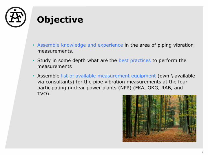
Objective
• Assemble knowledge and experience in the area of piping vibration
measurements.
• Study in some depth what are the best practices to perform the
measurements
• Assemble list of available measurement equipment (own \ available
via consultants) for the pipe vibration measurements at the four
participating nuclear power plants (NPP) (FKA, OKG, RAB, and
TVO).
3

Background
• Pipe vibration problems are often complex and cause long periods of
shut down
• Pipes that contain media under pressure (e.g. steam, water), which during a pipe break or leakage can cause
fire or other damage or trip of the machine shall be judged
• Modifications of pipes ALSO influence machinery dynamics
• Reduced power leading to large losses of income. Especially during
power uprate projects there have been large vibration problems at
the nuclear power plants.
• The current situation with low electricity prices has led to a new
situation where the NPPs are down regulated.
• This might lead to increased wear, tear and vibration levels.
• The vibration experts at the nuclear power plants have expressed a
desire to increase the in-house knowledge on measurement,
analysis and mitigation of vibrations in different components.
• There are only a few experts within the field and many expert are close to retirement.
4

Pipe vibration sourcesEx. Where does pipe vibrations come from?
1. Mechanical Induced Sources –- Machinery Unbalanced Forces and Moments
2. Pulsation Induced Sources –- Reciprocating/Centrifugal Compressor and Pumps, Turbine Flow through, Valves, Orifice plates
3. Cavitation and flashing
4. Vortex shedding
5. Acoustical resonance
6. Water- and Steamhammer
5
Sometimes, a scary subjective feeling!
Purchase requirement
Utilized purchase requirements on pipes and valves.
• Vibration criteria for connecting pipes from machinary:
The overall vibration level in the frequency range 1-1000 Hz
shall be measured using vibration velocity in mm/s rms and
vibration displacement in microns peak.
If the vibration level is above 7 mm/s rms or above 150
microns peak, steps shall be taken by the Contractor to reduce
the vibrations.
• Requirements are generally not set on pipes but on on valves and
then in terms of max. acceleration which has been determined by
calculation.
6

Piping vibration evaluationcriteria – Vibration requirements
• ASEA STAAL standard, rule of thumb levels are presented > 20 mm/s danger <8 mm/s OK
• VDI 3842 (as function of frequency)
• ASME OM-SG-2007, 12.7mm/s 0-peak
Note: Number of measurementpoints and locations are in mostcases to be decided by eachspecific project or vibration specialist

Best Practice – Vibration requirements
Use standards together with your own ”common sense”
• Acceptable stress and vibration levels depend on many factors, a few of which are:
• Material (composition, strength, endurance, etc.)
• Geometry (size, quality of manufacturing, stress concentrations such as tee-
intersections and cutouts, etc.)
• Number of stress cycles
• Amount of residual static stress.
8
Example of stress concentration

What to look for – describe the symptom
– prepare for measurement?
1. Frequency of vibration. Is it low frequency below 10 Hz, medium up to 300 Hz or high frequency?
Select appropriate vibration sensor -s?
2. Amplitude of vibrationsevere vibration - validated against requirement?
3. Location of highest vibrationOn a pipe, pipe support, valve etc?Decide if other complementary sensors are necessary strain, pressure etc.
4. Identify which kind of vibrations it is, steady state, transient or random vibrations
Select time domain for transient vibration
Select frequency for steady state
5. Identify mode shape or vibration pattern of local pipe component and global pipe system This step may require a deeper understanding of vibration methods.
ODS measurement and FE calculations
9

Selection of vibration sensor
Best Practice
• Often depends on frequency bandwidth
o Acceleration: accelerometers 2-1600 Hz or higher (use piezo resistive
accelerometer for strong shock measurements to avoid overload at higher
frequencies)
o Velocity (mechanical): velocity sensors 10-1600 Hz or higher(=no electronic
linearization)
o Displacement: LVDT sensors Dc-30 Hz
10
Upper frequency range is depending on vibration requirements (often up to 1000Hz) but in practice up to some hundred Hz. However depending on equipment (pumps, compressors, motors, valves, orifices, bellows) it could be wise if possible to choose 2 kHz and sometimes even higher but seldom over 4-5 kHz.

Pro and Cons – Velocity Sensor (VS) and Accelerometer (ACC)
+ For frequencies below 100Hz, VS provides a much larger signal than a
conventional PACC (Piezoelectric Accelerometer Sensor)
- ACC overloads compromise low amplitude and low frequency signal
- VS has lower sensitivity to higher frequencies.
+ ACC with additional LP filters might be better (however not so straight
farward)
- VS are heavy compared to ACC
11
The resonant frequencies of the
velocity sensors are at 8 Hz or
15 Hz depending upon their different
constructional features.
Through electronic linearization of
the respective frequency range it is
possible to also measure vibrations
that lie well below these
resonant frequencies with high
accuracy.

How to select measurementpoints
Best Practice
Pipe measurement points are selected from an ISOMETRI drawing
and not so often by subjected walkdowns. The selected
measurement points from the ISOMETRI have preferable
connection to a fatigue pipe design calculation model where
fatigue hot spots have been determined.
Alternative pipe measurement points are selected from know-
hows experiences i.e. similar experiences from sister blocks
Limited by accessibility of the measurement location and areas
CFD calculations – Thermohydraulic simulation
12

Safe for Heat and RadiationBest Practice: Long term measurements
• Example
13
A: Piezoelectric charge sensor (no electronics inside sensor)
B: Raychem cable or any other radiation harded cable (expensive, kept as short as possible)
D: Charge Converter/Amplifier (convert the high impedance output of a charge mode piezoelectric
transducer to a low-impedance voltage output. This allows a long cables to minimize noise.)
E: Low noise cable i.e. good twisted pair shielded coax. cable (may be long)
F: ICP converter
H: Measurement system
• PVC material is not accepted in hot environments and fixed cable installations due to risk of fire which may spread particles. Use glass fiber armed cable instead.
• Teflon is not allowed in radiation area.

Short term vibration measurementsEx. Inside containment
14
Magnetic mounting Neodymium
magnets are the strongest type of permanent magnet commercially available.
+
accelerometer
Long trash stick

Checking consistency of the collected data
• Measurement performed in correct time slot?
• Are there signal disturbances, noise, ski-slope=overload etc?
• It’s prudent to keep track of loading condition, flow, speed of
adjacent machinary and other system parameters which can give
influence to pipe vibration before you can evaluate the reliability
etc?
15
0 1301005010 20 30 40 60 70 80 90 110 120
Hz
B:10:+Z (CH31)
650
950
700
800
900
680
720
740
760
780
820
840
860
880
920
s
Tim
e
0.00
250e-6
Am
plit
ude
m/s
6.01
712.70
885.60 198e-6
Spectrum B:10:+Z WF 9601 [0-2400 s]
Ex. Can ~5 s measurement alwaysreveal correct levels?

Sensor mounting Accelerometer
Ex. Accelerometers on pipe (no isolation)
16
U-clamps

Sensor mounting Velocity sensor
Ex. Velocity sensor on pipe with isolation
17
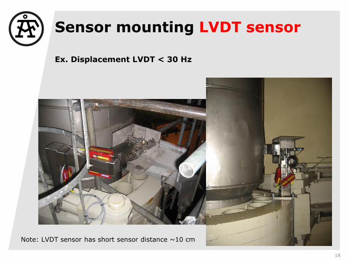
Sensor mounting LVDT sensor
Ex. Displacement LVDT < 30 Hz
18
Note: LVDT sensor has short sensor distance ~10 cm

Instrumentation
Available instruments at NPP sites
• Handheld: CSI (1-2 ch), VibXpert (1-2 ch), Svantek (4-ch), SKF
Microlog, Percon logger (Noiden)
• Multichannel systems: CSI2600, Oros OR-38 multichannel, Oros OF
-24 multichannel, BERAN 766 , LMS Scadas
• Analysis ODS+Modal: ME-Scope, LMS TestLab
19

Measurements for Trouble shooting –
ODS Operational Deflection Shapes
• In this case it was very difficult to know if the main pipe itself had global modes which
affected the SBC vibrations or if the high detected vibrations at the flanges of the SBC
were local. The most efficient way to find out was to perform a multichannel ODS where
you can easy determine the vibrations relative phase behavior for bending, torsion, shell
modes and how the main pipe modes affects the SBC.
20

Measurement for trouble shooting –Acoustic emission (AE)
21
The AE-envelope sensor is DC coupled which means that it both capture the slow and fast varying trends in the steam pipe, for instance slowly increase/decrease of air flow, along with the sudden impacts of pulsation hitting the probe.
AE is a good complement to ODS measurement to determine the measured load case in the ODS measurements
0 3010 202 4 6 8 12 14 16 18 22 24 26 28
s
340
850
400
500
600
700
800
450
550
650
750
Am
plit
ude
g
0.00
1.00
Am
plit
ude
F 1:1 Run 462 Fri Jul 01 2011 05:44:51
0 3010 202 4 6 8 12 14 16 18 22 24 26 28
s
-7
7
0
-5
5
-4
-3
-2
-1
1
2
3
4
Real
g
0.00
1.00
Am
plit
ude
F 2:2 Run 462 Fri Jul 01 2011 05:44:51
0 3010 202 4 6 8 12 14 16 18 22 24 26 28
s
-6
7
0.0
5.0
-4.0
-3.0
-2.0
-1.0
1.0
2.0
3.0
4.0
Real
g
0.00
1.00
Am
plit
ude
F 3:3 Run 462 Fri Jul 01 2011 05:44:51
AE
Accelerometer
(Shock Pulse)

Thank you all!!
Questions?
22