Native PCI Express RS232 Serial Adapter Card with 16950 UART

Connect Tech Inc. Tel: 519-836-1291
42 Arrow Road Toll: 800-426-8979 (North America only) Guelph, Ontario Fax: 519-836-4878 N1K 1S6 Email: [email protected] www.connecttech.com [email protected] CTIM-00442 Revision 0.04 2015-07-08
Mini PCI Express Card, Asynchronous Serial
Users Guide

Mini PCI Express Card Serial
Users Guide
www.connecttech.com
Document: CTIM-00442
Revision: 0.04 Page 2 of 16
Connect Tech Inc. 800-426-8979 | 519-836-1291
Date: 2015-07-08
Table of Contents
Table of Contents ................................................................................................................................... 2
Preface ................................................................................................................................................... 3
Customer Support Overview ........................................................................................................................... 3 Contact Information ........................................................................................................................................ 3 Limited Mini PCI Express Warranty ............................................................................................................... 4 Copyright Notice ............................................................................................................................................. 4 Trademark Acknowledgment .......................................................................................................................... 4 ESD Warning .................................................................................................................................................. 5
Revision History .................................................................................................................................... 5
Introduction........................................................................................................................................... 6
Product Features and Specifications ................................................................................................................ 6 Part Numbers / Ordering Information ............................................................................................................. 7
Product Overview .................................................................................................................................. 8
Block Diagrams ............................................................................................................................................... 8 USB 2-Port Non-Isolated ...................................................................................................................... 8 PCI-Express 2-Port Isolated ................................................................................................................. 9
Interface Pin-Outs ............................................................................................................................... 10
USB 2-Port Non-Isolated Model ................................................................................................................... 10 PCI-Express 2-Port Isolated Model ............................................................................................................... 11 Mini PCIe Edge Connector ........................................................................................................................... 12
Setup and Operation ............................................................................................................................ 13
RS485 (or Half Duplex) Mode Operation ..................................................................................................... 14
Typical Installation .............................................................................................................................. 15
Mini PCI-Express Card Installation .............................................................................................................. 15
Cable Attachment ................................................................................................................................ 15
Software .............................................................................................................................................. 16
USB Host Interface Products ........................................................................................................................ 16 PCI-Express Host Interface Products ............................................................................................................ 16
Mini PCI Express Card Serial
Users Guide
www.connecttech.com
Document: CTIM-00442
Revision: 0.04 Page 3 of 16
Connect Tech Inc. 800-426-8979 | 519-836-1291
Date: 2015-07-08
Preface
Customer Support Overview
If you experience difficulties after reading the manual and/or using the product, contact the Connect Tech
reseller from which you purchased the product. In most cases the reseller can help you with product installation
and difficulties.
In the event that the reseller is unable to resolve your problem, our highly qualified support staff can assist you.
Our support section is available 24 hours a day, 7 days a week on our website at:
www.connecttech.com/sub/support/support.asp. See the contact information section below for more
information on how to contact us directly. Our technical support is always free.
Contact Information
Mail/Courier Connect Tech Inc.
Technical Support
42 Arrow Road
Guelph, Ontario
Canada N1K 1S6
Email/Internet
www.connecttech.com
Note:
Please go to the Download Zone or the Knowledge Database in the Support Center on the Connect Tech
website for product manuals, installation guides, device driver software and technical tips.
Submit your technical support questions to our customer support engineers via the Support Center on the
Connect Tech website.
Telephone/Facsimile
Technical Support representatives are ready to answer your call Monday through Friday, from 8:30 a.m. to
5:00 p.m. Eastern Standard Time. Our numbers for calls are: Toll Free: 800-426-8979 (North America only)
Telephone: 519-836-1291 (Live assistance available 8:30 a.m. to 5:00 p.m. EST, Monday to Friday)
Facsimile: 519-836-4878 (on-line 24 hours)

Mini PCI Express Card Serial
Users Guide
www.connecttech.com
Document: CTIM-00442
Revision: 0.04 Page 4 of 16
Connect Tech Inc. 800-426-8979 | 519-836-1291
Date: 2015-07-08
Limited Mini PCI Express Warranty
Connect Tech Inc. provides a 2-Year Warranty for all Connect Tech Inc. products. Should this product, in
Connect Tech Inc.'s opinion, fail to be in good working order during the warranty period, Connect Tech Inc.
will, at its option, repair or replace this product at no charge, provided that the product has not been subjected
to abuse, misuse, accident, disaster or non-Connect Tech Inc. authorized modification or repair.
You may obtain warranty service by delivering this product to an authorized Connect Tech Inc. business
partner or to Connect Tech Inc. along with proof of purchase. Product returned to Connect Tech Inc. must be
pre-authorized by Connect Tech Inc. with an RMA (Return Material Authorization) number marked on the
outside of the package and sent prepaid, insured and packaged for safe shipment. Connect Tech Inc. will
return this product by prepaid ground shipment service.
The Connect Tech Inc. 2-Year Warranty is defined as the serviceable life of the product. This is defined as the
period during which all components are available. Should the product prove to be irreparable, Connect Tech
Inc. reserves the right to substitute an equivalent product if available or to retract the 2-Year Warranty if no
replacement is available.
The above warranty is the only warranty authorized by Connect Tech Inc. Under no circumstances will
Connect Tech Inc. be liable in any way for any damages, including any lost profits, lost savings or other
incidental or consequential damages arising out of the use of, or inability to use, such product.
Copyright Notice
The information contained in this document is subject to change without notice. Connect Tech Inc. shall not
be liable for errors contained herein or for incidental consequential damages in connection with the furnishing,
performance, or use of this material. This document contains proprietary information that is protected by
copyright. All rights are reserved. No part of this document may be photocopied, reproduced, or translated to
another language without the prior written consent of Connect Tech, Inc.
Copyright 2015 by Connect Tech, Inc.
Trademark Acknowledgment
Connect Tech, Inc. acknowledges all trademarks, registered trademarks and/or copyrights referred to in this
document as the property of their respective owners. Not listing all possible trademarks or copyright
acknowledgments does not constitute a lack of acknowledgment to the rightful owners of the trademarks and
copyrights mentioned in this document.

Mini PCI Express Card Serial
Users Guide
www.connecttech.com
Document: CTIM-00442
Revision: 0.04 Page 5 of 16
Connect Tech Inc. 800-426-8979 | 519-836-1291
Date: 2015-07-08
ESD Warning
Electronic components and circuits are sensitive to
ElectroStatic Discharge (ESD). When handling any circuit
board assemblies including Connect Tech COM Express
carrier assemblies, it is recommended that ESD safety
precautions be observed. ESD safe best practices include,
but are not limited to:
Leaving circuit boards in their antistatic packaging
until they are ready to be installed.
Using a grounded wrist strap when handling circuit
boards, at a minimum you should touch a grounded
metal object to dissipate any static charge that may be
present on you.
Only handling circuit boards in ESD safe areas, which
may include ESD floor and table mats, wrist strap
stations and ESD safe lab coats.
Avoiding handling circuit boards in carpeted areas.
Try to handle the board by the edges, avoiding contact
with components.
Revision History
Revision Date Author(s) Change
0.00 2015-04-0 RCD Preliminary
0.01 2015-05-28 RCD First Release
0.02 2015-06-04 BY RCD
Update cable image on page 10 Update board image on page 9. Update Cable numbers on pages 10 and 11.
0.03 2015-07-02 RCD Correct Cable information for MPG003.
0.04 2015-07-08 RCD Add configuration switch orientation sketch.

Mini PCI Express Card Serial
Users Guide
www.connecttech.com
Document: CTIM-00442
Revision: 0.04 Page 6 of 16
Connect Tech Inc. 800-426-8979 | 519-836-1291
Date: 2015-07-08
Introduction
The Mini PCI Express offers dependability and high speed data transfer rates in a very small form factor - Mini PCI
Express card.
Available with 2 or 4 ports of RS-232/422/485 connectivity, these PCI Express x1 lane cards are compatible with
x1, x4, x8, x16 lane PCI Express slots. Bi-directional data speeds up to 20 Mbps (depending on the model, using
RS-422/485) ensure fast data acquisition and communications. Experience more responsiveness with full modem
control signals while reducing the load on your network.
Product Features and Specifications
Specifications
Feature MPG001 MPG002[1] MPG003 MPG004[1]
Host Bus Interface USB-2 PCI-Express (x1 lane)
Number of Ports 2 2
Isolation None 700V DC 500V (60Hz AC, sin wave)
IO Connector 1 x 20 pins Latching (MiniTek) Non-Latching (2mm pitch header)
2 x 10 pins Latching (MiniTek) Non-Latching (2mm pitch header)
Line Interface Hardware Selectable RS232/422/485 Hardware or Software Selectable RS232/422/485
Serial Signals RS232: TxD, RxD, RTS, CTS, DTR, DCD, DSR, RI, GND
RS422/485: TX, RX, GND
RS232: TxD, RxD, RTS, CTS, DTR, DCD, DSR, RI, GND
RS422/485: TX, RX, GND
Max Bit Rates [2] RS232: Up to 921.6Kbps RS422/485: Up to 12Mbps Slow Slew Rate: Limited to 250Kbps
RS232: Up to 921.6Kbps RS422/485: Up to 20Mbps Slow Slew Rate: Limited to 250Kbps
Interrupts N/A Assigned by Plug&Play
Memory Addresses N/A Assigned by Plug&Play
Uart Type USB Uart with 4K FIFO’s (TX & RX) PCIe Uart with 256 byte FIFO’s (TX & RX)
Dimensions 51 x 30mm Conforms to Mini Card EMS “Full” size
51 x 30mm Conforms to Mini Card EMS “Full” size
Environment Storage & Operating Temp: -40 to +85C 5 to 95% humidity (non-condensing)
Storage & Operating Temp: -40 to +85C 5 to 95% humidity (non-condensing)
Notes:
1. Part number has non-latching connector.
2. Maximum bit rates are indicated for the board hardware. Attainable and/or sustainable maximum bit
rate will depend on other system hardware, software or application.

Mini PCI Express Card Serial
Users Guide
www.connecttech.com
Document: CTIM-00442
Revision: 0.04 Page 7 of 16
Connect Tech Inc. 800-426-8979 | 519-836-1291
Date: 2015-07-08
Part Numbers / Ordering Information
Part Number
MPG001, MPG002 USB 2-Port Models
MPG003, MPG004 PCI-Express 2-Port Isolated Models
MPG0xx PCI-Express 4-Port Models (Product not available yet)
Mini PCI Express Card Serial
Users Guide
www.connecttech.com
Document: CTIM-00442
Revision: 0.04 Page 8 of 16
Connect Tech Inc. 800-426-8979 | 519-836-1291
Date: 2015-07-08
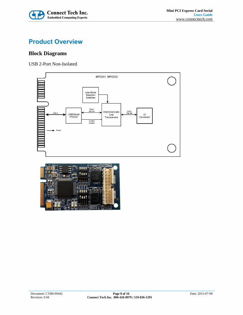
Product Overview
Block Diagrams
USB 2-Port Non-Isolated

Mini PCI Express Card Serial
Users Guide
www.connecttech.com
Document: CTIM-00442
Revision: 0.04 Page 9 of 16
Connect Tech Inc. 800-426-8979 | 519-836-1291
Date: 2015-07-08
PCI-Express 2-Port Isolated

Mini PCI Express Card Serial
Users Guide
www.connecttech.com
Document: CTIM-00442
Revision: 0.04 Page 10 of 16
Connect Tech Inc. 800-426-8979 | 519-836-1291
Date: 2015-07-08
Interface Pin-Outs
USB 2-Port Non-Isolated Model These models use a single 2mm header, either latching of non-latching depending on the model (latching
model shown).
Port-1 is connector P1 on the board, Port-2 is P2. Although, these 2 connectors are joined to form on physical
connector.
Notes:
[1] DB-9 pin assignments when using cable CBG121 (CTIC-00380)
Port Pin DB9
Pin [1]
RS232 RS422 RS485
1
1 1 DCD --- ---
2 6 DSR TX- TXRX-
3 2 RXD TX+ TXRX+
4 7 RTS RX- ---
5 3 TXD RX+ ---
6 8 CTS --- ---
7 4 DTR --- ---
8 9 RI --- ---
9 5 GND GND GND
10 --- --- --- ---
2
11 1 DCD --- ---
12 6 DSR TX- TXRX-
13 2 RXD TX+ TXRX+
14 7 RTS RX- ---
15 3 TXD RX+ ---
16 8 CTS --- ---
17 4 DTR --- ---
18 9 RI --- ---
19 5 GND GND GND
20 --- --- --- ---

Mini PCI Express Card Serial
Users Guide
www.connecttech.com
Document: CTIM-00442
Revision: 0.04 Page 11 of 16
Connect Tech Inc. 800-426-8979 | 519-836-1291
Date: 2015-07-08
PCI-Express 2-Port Isolated Model These models use two 2mm headers, either latching of non-latching depending on the model (latching model
shown).
Port-1 is connector P1 on the board, Port-2 is P2.
Notes:
[1] DB-9 pin assignments when using cable CBG191 (CTIC-00539)
Pin DB9
Pin [1]
RS232 RS422 RS485
1 1 DCD --- ---
2 6 DSR TX- TXRX-
3 2 RXD TX+ TXRX+
4 7 RTS RX- ---
5 3 TXD RX+ ---
6 8 CTS --- ---
7 4 DTR --- ---
8 9 RI --- ---
9 5 GND GND GND
10 --- --- --- ---
Mini PCI Express Card Serial
Users Guide
www.connecttech.com
Document: CTIM-00442
Revision: 0.04 Page 12 of 16
Connect Tech Inc. 800-426-8979 | 519-836-1291
Date: 2015-07-08
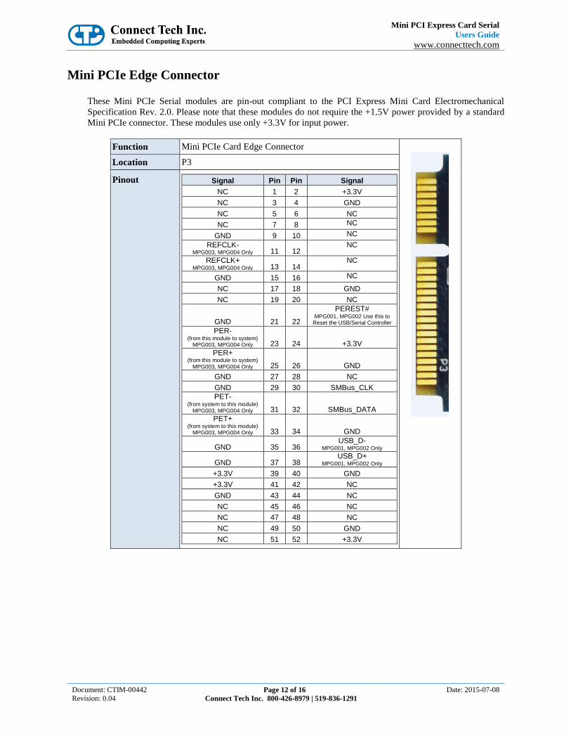
Mini PCIe Edge Connector
These Mini PCIe Serial modules are pin-out compliant to the PCI Express Mini Card Electromechanical
Specification Rev. 2.0. Please note that these modules do not require the +1.5V power provided by a standard
Mini PCIe connector. These modules use only +3.3V for input power.
Function Mini PCIe Card Edge Connector
Location P3
Pinout Signal Pin Pin Signal
NC 1 2 +3.3V
NC 3 4 GND
NC 5 6 NC
NC 7 8 NC
GND 9 10 NC
REFCLK- MPG003, MPG004 Only 11 12
NC
REFCLK+ MPG003, MPG004 Only 13 14
NC
GND 15 16 NC
NC 17 18 GND
NC 19 20 NC
GND 21 22
PEREST# MPG001, MPG002 Use this to
Reset the USB/Serial Controller PER-
(from this module to system) MPG003, MPG004 Only 23 24 +3.3V
PER+ (from this module to system)
MPG003, MPG004 Only 25 26 GND
GND 27 28 NC
GND 29 30 SMBus_CLK
PET- (from system to this module)
MPG003, MPG004 Only 31 32 SMBus_DATA
PET+ (from system to this module)
MPG003, MPG004 Only 33 34 GND
GND 35 36 USB_D-
MPG001, MPG002 Only
GND 37 38 USB_D+
MPG001, MPG002 Only
+3.3V 39 40 GND
+3.3V 41 42 NC
GND 43 44 NC
NC 45 46 NC
NC 47 48 NC
NC 49 50 GND
NC 51 52 +3.3V

Mini PCI Express Card Serial
Users Guide
www.connecttech.com
Document: CTIM-00442
Revision: 0.04 Page 13 of 16
Connect Tech Inc. 800-426-8979 | 519-836-1291
Date: 2015-07-08
Setup and Operation The USB 2-Port Non-Isolated and PCI-Express 2-Port Isolated models share the same configuration setting
mechanism.
Each Port has a 4-Position switch which sets the mode for the Port. Positions #1 and #2 set the primary mode
for the port. Positions #3 and #4 perform secondary setup functions.
The physical orientation of these switches is different for each model, however each uses the same type
of switch block.
The “ON” position is show here for switch position #1, others are “OFF”,
M0 M1 Serial Mode
OFF OFF Loopback [1]
ON OFF RS232
OFF ON RS485 (Half Duplex)
ON ON RS422 (Full Duplex)
Term Function Slow Slew Function
ON 120 ohm Receiver Termination enabled ON Slow Slew Rate enabled
OFF Termination disabled OFF Slow Slew Rate disabled
Notes:
1. Loopback mode connects TXRX / RTSCTS, DSR, RI / DTRDCD at the Line Interface device, and
can be used to test the board operation without the need to external wrap-back connectors.
2. The termination function only works in RS422 or RS485 modes.
3. Slow Slew Rate works in any mode except loopback. When Slow Slew Rate is enabled, the baud rate is
limited to about 250K bps in any mode. Slow Slew rate is used to limit EMI emissions.

Mini PCI Express Card Serial
Users Guide
www.connecttech.com
Document: CTIM-00442
Revision: 0.04 Page 14 of 16
Connect Tech Inc. 800-426-8979 | 519-836-1291
Date: 2015-07-08
RS485 (or Half Duplex) Mode Operation This mode requires that the RTS signal be enable (turned On) prior to data transmission, then disabled (turned
Off) in order to allow data reception. This can be handled autonomously by the UART if appropriate Driver
software is employed.

Mini PCI Express Card Serial
Users Guide
www.connecttech.com
Document: CTIM-00442
Revision: 0.04 Page 15 of 16
Connect Tech Inc. 800-426-8979 | 519-836-1291
Date: 2015-07-08
Typical Installation
Mini PCI-Express Card Installation Most Mini-PCIe connector vendors (or system vendors) specify an “installed” space as either dimension A or
B in their drawings (or manuals).
Dimension A is from the surface of the system board to the centerline of the Mini-PCI-Express Card.
Dimension B is from the surfaces of the two cards. B is always 0.5mm smaller than A, because Mini PCI-
Express Cards are always 1mm thick.
The Connect Tech Mini PCI-Express Card Serial products have components and protrusions on the back side
of the card which require that they be installed in Mini PCI-Express card sockets which provide Dimension B
of 2.3mm or greater. Also, if there are any components on the system board, under the Mini PCI-Express Card,
then extra space may be required.
CAUTION: Always check whether any part of the Mini PCI-Express card is touching the system board and/or
components on the system board before powering the system. Failure to do so may result in damage to the
Mini PCI-Express card or the system.
Cable Attachment Certain models of these products have a “MiniTek” style latching connector for attachment of the interface
cable. The plug on the cable is keyed so it will only go into the connector one way.
To attach, push the cable into the board connector until a small “click” is heard (or felt). Once installed the
latch holds the cable to the board connector.
To release the cable, squeeze (and hold) on the edge of the clip and then pull the cable away from board
connector.

Mini PCI Express Card Serial
Users Guide
www.connecttech.com
Document: CTIM-00442
Revision: 0.04 Page 16 of 16
Connect Tech Inc. 800-426-8979 | 519-836-1291
Date: 2015-07-08
Software
USB Host Interface Products The products which use the USB Host interface use the FTDI FT2232 USB/Uart device. There are two
different types of Drivers available on the FTDI website for this device. The “VCP” (or Virtual COM Port)
Driver is most commonly used.
http://www.ftdichip.com/Products/ICs/FT2232H.htm
PCI-Express Host Interface Products The products which use the PCI-Express Host interface use the Exar 17V352 Uart device. The Connect Tech
BlueStorm/Express (Windows) Driver is available which will recognize and operate the Uart on this product.