Waste Treatment and Immobilation Plant HLW Waste Vitrification ...
1
A MULTIBRANCH BOREHOLE APPROACH TO HLW DISPOSAL
J. S. Gibbs, J. Buongiorno, M. J. Driscoll (MIT)
Massachusetts Institute of Technology
Dept. of Nuclear Science and Engineering
77 Massachusetts Ave., Room 24-215A
Cambridge, MA 02139 USA
A study was carried out to quantify the benefits of
adapting the latest state-of-the-art in oil/gas well drilling
technology to deep boreholes for disposal of spent LWR
fuel or its post-reprocessing waste forms. It is now
common practice to drill as many as a dozen side-wells at
angles up to horizontal from a single vertical shaft. For
HLW disposal this has several attractive features:
significant cost savings; avoidance of excessive
hydrostatic, canister stack crushing, and lithostatic
pressures; and the need to securely plug many fewer
vertical shafts.
A major subtask involved development of a computer
code for predicting hole preparation cost as a function of
more than a dozen key variables while allowing for
parameter uncertainty. Enhanced geothermal system
(EGS) cost data were employed to calibrate the code. The
projected total cost of a US borehole repository field
(including drilling, consolidating and encapsulating the
fuel, emplacement and closure) was found to be about 70
$/kg HM for an optimized field of holes using ten 2 km
long laterals inclined 20° from the horizontal.
Mechanical and thermal analyses were also carried
out to confirm acceptable system performance over an
indefinitely long post-emplacement history.
The overall conclusion is that this variation on the
deep borehole HLW disposal option is well worth
considering as a preferred alternative.
I. INTRODUCTION
The unsettled status of the US nuclear waste disposal
program has led to renewed interest in the use of deep
boreholes, drilled several kilometers deep into granitic
basement rock, as an alternative. Most studies have
considered vertical holes having a 2 km emplacement
zone under 1 km of caprock, e.g., see Jensen this
Conference1 and Hoag.2 The new work reported on here
evaluates the application of state-of-the-art oil/gas
multibranch well technology to nuclear HLW disposal
because it offers both lower cost and enhanced
confinement.3
Reference 4 describes multibranch drilling
techniques, which have become progressively more
sophisticated over the past two decades. Suffice it to note
that commercial vendors can now provide holes of the
type needed, in completed form with as many as a dozen
lined side branches. Figure 1 shows in schematic fashion
some of the many ways in which waste emplacement
boreholes can be arranged around a single vertical mother
hole. Table I lists typical parameters, and Table II
summarizes pros and cons, focusing on differences which
distinguish multibranch and single shaft boreholes.
The sections which follow address key issues carried
over from the long history of similar evaluations done for
shallower mined repositories, such as thermal loading
limits and, of course, costs.
II. ANALYSIS OF THERMAL PERFORMANCE
One legacy of shallower mined repository
assessments is a preoccupation with thermal conditions in
both the waste canisters and the host rock. Borehole
repositories, because of their inherently much smaller
canister diameters (e.g., capable of housing only one
PWR assembly) have a lower linear heat generation rate
(W/m, see Table I) and would be expected to engender
much less concern in this regard. However, quantitative
confirmation is clearly called for. In the work reported
here this was addressed using both analytic modeling in
1-D, and 2- and 3-D computer code (Solidworks) models
of the bilateral configuration on the right in Fig. 1. Both
approaches are rather straightforward, with performance
dominated by conduction inside the simulated waste
canisters and in the surrounding host rock, with radiation

2
to and from steel canister walls and borehole liner steel
tubes.
Table III summarizes the more important parameters
involved.
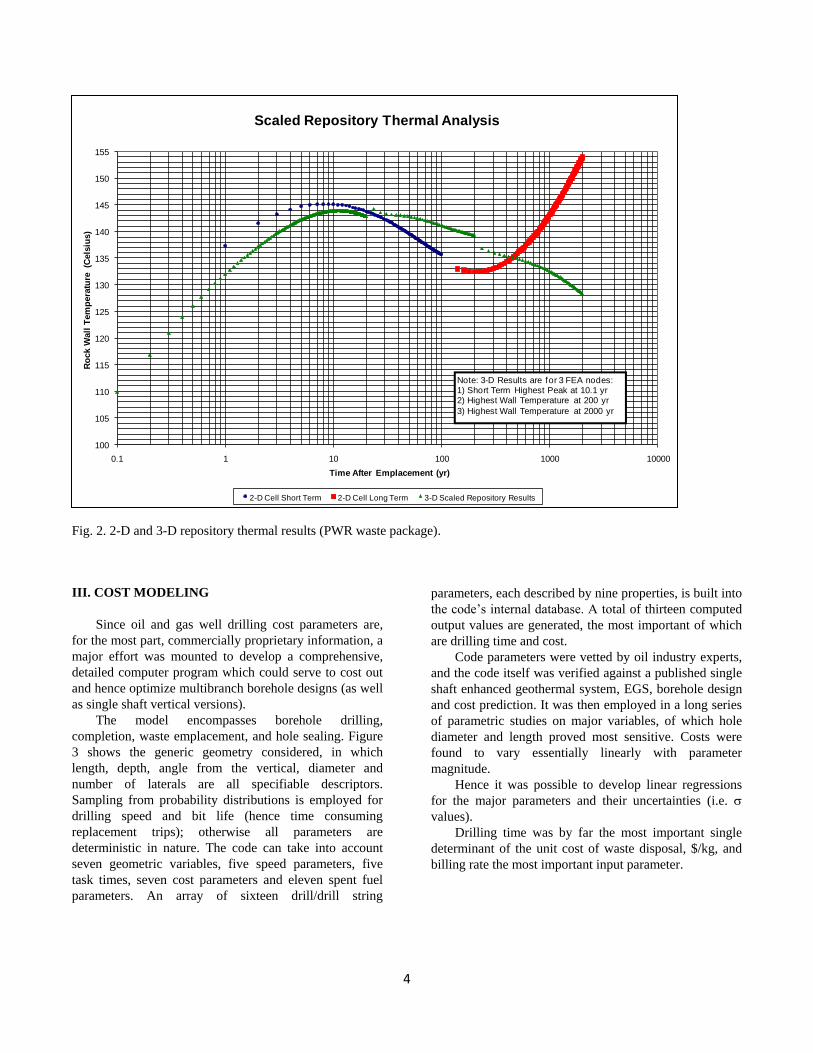
Fig. 2 shows the time dependent temperature of the
borehole wall calculated using the 2- and 3-D finite
element code. As can be seen, it reaches a maximum of
145°C at about ten years after emplacement. The waste
(consolidated PWR assembly) centerline temperature
maximum occurs at the same time and is 181°C (not
shown). Both values are quite tolerable based on Yucca
Mountain requirements. Reprocessed waste forms, partly
by design, have lower linear heat generation rates than
reconstituted spent commercial fuel packages and should
yield lower wall peak temperatures.
The 2-D model used a surrounding far-field host rock
temperature of 100°C and adiabatic boundary conditions
on all unheated surfaces with a unit cell representing a
200m by 60m block surrounding the emplacement hole
(reflecting the vertical and horizontal spacing of
repository laterals). The 3-D models five emplacement
laterals in a granitic slab 3500m deep by 2500m wide and
100m thick. This model features fixed temperature
conditions of 25°C at the surface and 109°C at 3500m
with adiabatic boundary conditions on the remaining
unheated surfaces. In both analyses, the finite element
mesh was sized according to geometrical curvature of the
model resulting in finest resolution near the heated
borehole wall.
In Fig. 2 note that the 2-D results increase
monotonically after several hundred years. This is
because an unrealistic adiabatic rock cell wall boundary
condition is imposed. The 3-D results correctly allow for
vertical heat losses, and therefore decline monotonically
after the initial peak. Hence this effect must be taken into
account in borehole performance assessments.
The apparent discontinuities in the 3-D plot arise from
tracking the temperature histories of finite element nodes
at different points along the length of the borehole wall
for the near, mid, and far term.
TABLE I. Multibranch Well Characteristics
Host Rock
Type: basement granite with < 500 m sedimentary overburden
Key properties:
< 10 microdarcy permeability
< 1% porosity
benign pH: >6, <9
reducing chemistry, Eh < 0.1 volt
Boreholes
Plug zone length = 1500 m
Spacing between vertical kickoffs: > 30 m
Radius of curvature ≥ 230 m
Emplacement branch lengths ~ 2000 m
Branch vertical slope 1:5
Number of branches: 10 (ref. design)
Lateral bit dia: 11.625 (29.5 cm)
Liner pipes: 26 (17.5/11 5/8)
Total capacity: ~ 4000 canisters;
Sufficient for one 1 GWe PWR over its 60-80 year lifetime
Waste Package
19.5 cm OD, 5 m long
P-110 drill string steel
301 PWR fuel pins (close packed)
(compare to 264 fueled rods in typical 17 × 17 assembly)
Post-reactor cooling: 40 years
Initial linear power at time of emplacement: 37 W/m
Improves with depth

3
TABLE II. Multibranch Well Attributes
A. Advantages of Multibranch Boreholes
As many as a dozen side branches can be drilled per central vertical hole, hence:
Easier to have greater average depth of waste entombment zone
The absence of a self-heated vertical chimney effect on water buoyancy eliminates a hypothetical escape
mechanism
Considerably lower cost due to reduced drilling time and rig relocation
Only one plug needed in caprock zone; it can be longer and more elaborate
Eliminates crushing of lower canisters by the stack above
B. Disadvantages of Multibranch Boreholes
Commercial experience is with smaller diameter side branches than for vertical-only
wells, hence:
This favors reconstitution of PWR (but not BWR) spent fuel bundles – at added expense
Thus reprocessed waste forms are preferred
Retrieval is more difficult, especially after plugging
Fig. 1. Schematic of potential multibranch borehole configurations (hole diameters at left greatly exaggerated).
TABLE III. Summary of Thermal Design Study Properties and Parameters
Granite Material Properties
Thermal conductivity 2.2 W/m-K
Density 2500 kg/m3
Specific heat capacity 790 J/kg-K
Repository Properties
Surface temperature 25°C
Subterranean thermal gradient 24°C/km
Cooling time before emplacement 40 years
BWR fueled length 4.1 m
PWR fueled length 4.2 m
Shaft spacing 200 m
Borehole spacing 5 km
Canister, Waste and Fill Thermal Properties
Steel thermal conductivity 50.2 W/m-K
Steel (oxidized) emissivity 0.79
PWR & BWR fuel pin thermal conductivity 1.87 W/m-K
Void space fill thermal conductivity 0.33 W/m-K
Borehole wall diameter 29.5 cm
Waste canister ID 18.1 cm
Initial linear power 37 W/m
4
Fig. 2. 2-D and 3-D repository thermal results (PWR waste package).
III. COST MODELING
Since oil and gas well drilling cost parameters are,
for the most part, commercially proprietary information, a
major effort was mounted to develop a comprehensive,
detailed computer program which could serve to cost out
and hence optimize multibranch borehole designs (as well
as single shaft vertical versions).
The model encompasses borehole drilling,
completion, waste emplacement, and hole sealing. Figure
3 shows the generic geometry considered, in which
length, depth, angle from the vertical, diameter and
number of laterals are all specifiable descriptors.
Sampling from probability distributions is employed for
drilling speed and bit life (hence time consuming
replacement trips); otherwise all parameters are
deterministic in nature. The code can take into account
seven geometric variables, five speed parameters, five
task times, seven cost parameters and eleven spent fuel
parameters. An array of sixteen drill/drill string
parameters, each described by nine properties, is built into
the code’s internal database. A total of thirteen computed
output values are generated, the most important of which
are drilling time and cost.
Code parameters were vetted by oil industry experts,
and the code itself was verified against a published single
shaft enhanced geothermal system, EGS, borehole design
and cost prediction. It was then employed in a long series
of parametric studies on major variables, of which hole
diameter and length proved most sensitive. Costs were
found to vary essentially linearly with parameter
magnitude.
Hence it was possible to develop linear regressions
for the major parameters and their uncertainties (i.e.
values).
Drilling time was by far the most important single
determinant of the unit cost of waste disposal, $/kg, and
billing rate the most important input parameter.
100
105
110
115
120
125
130
135
140
145
150
155
0.1 1 10 100 1000 10000
Ro
ck W
all
Tem
pera
ture
(C
els
ius)
Time After Emplacement (yr)
Scaled Repository Thermal Analysis
2-D Cell Short Term 2-D Cell Long Term 3-D Scaled Repository Results
Note: 3-D Results are for 3 FEA nodes:1) Short Term Highest Peak at 10.1 yr2) Highest Wall Temperature at 200 yr
3) Highest Wall Temperature at 2000 yr

5
Fig. 3. Nominal repository configuration – only one of many laterals shown.
The best overall case selected from some 20,000
potential repository configurations had features as
follows:
A 1500 meter vertical plug section for adequate
isolation of the nuclear waste from the biosphere
10 laterals extending from each vertical borehole
2000 meter long lateral emplacement shafts (400
packages/lateral)
Laterals declined 20° from horizontal
Drill-bit schedule calling for 26 for the surface
shaft, 17 ½ for the main vertical shaft and 11
5/8 for the laterals and radial kickoffs
The vertical shaft is lined and cemented at depths
below 2100 m, above which all casings are
removed to permit direct contact of the borehole
plug with the exposed granite rock face
Laterals are also lined with casing but these
liners are not cemented in place.
Part of the code’s graphic output is shown in Fig. 4.
Note the periodic interruptions as each lateral drift is
completed and filled with waste canisters. Smaller ripples
due to drillbit replacement are harder to see, but suggest
that advanced drilling technology may be beneficial in
this regard. Also note the linear accrual of expenditures
with time. Again advanced technologies currently
undergoing RD&D could reduce costs significantly: some
proponents claim speedup by factors of 2 – 5.
One important conclusion is that, as a result of the
highly detailed modeling of thermal effects and drilling
costs, it will be possible in the future to employ far
simpler formulations for borehole system design. Based
on the modeling in this project, drilling and emplacement
costs for this repository configuration are unlikely to
exceed $54/kg HM (median 51.2 $/kg; µ 51.3$/kg; σ
0.919 $/kg). Based on some conservative assumptions
built into the model (mature drilling techniques only,
equipment rental rates similar to those for a much larger
diameter and deeper enhanced geothermal well) this cost
estimate should be considered an upper limit on
directional drilling costs for lateral emplacement.
Additional costs for waste package fabrication, SiC fill,
fuel pin consolidation and canister sealing are expected to
not exceed $16/kg of HM for LWR spent fuel packages.
These costs are significantly lower for reprocessed or
vitrified wastes as they may be packaged into the final
disposal canister at the source site. Taken together, all
costs expected for a very-deep borehole approach amount
to about $70/kgHM, well within the DOE’s waste fund
fee (equivalent to ~$400/kgHM) even when transportation
costs to the repository and research and development
costs are considered. The multi-branch lateral
emplacement configuration is therefore demonstrated to
be economically feasible. However, further tradeoff
studies versus single-shaft vertical holes (e.g., Ref. 2) are
still in order.
IV. CONCLUSIONS
Deep borehole disposal of high level wastes from
nuclear reactor spent fuel has many attributes which
recommend this approach as a serious alternative to the
use of shallower mined repositories, and multibranch
versions in turn have much to recommend them over
single-shaft boreholes. Even better assurance of waste
confinement is the principal attraction. The major
impediment is not technological, but the policy decision

6
of how much emphasis to put on long-term retrievability.
Costs appear quite attractive, roughly $70/kgHM
compared to the ~$400/kgHM provided by the current 1
mill/kWhre waste fee. The savings from multibranching
override extra costs due to the need to reconstitute PWR
fuel assemblies – a cost not incurred if reprocessed waste
forms are involved. Finally, the upside of hole diameter
limits is that thermal limits on both the waste and host
rock are easily met, with large margins.
Fig. 4. Sample realization of final repository design.
7
REFERENCES
1. K. G. JENSEN and M. J. DRISCOLL, “Policy
Issues Associated with Deep Borehole HLW
Disposal,” International High-Level Radioactive
Waste Management Conference, Albuquerque,
April 2011
2. C. I. HOAG, “Canister Design for Deep
Borehole Disposal of Nuclear Waste,” SM
Thesis, MIT Dept. of Nuclear Science and
Engineering, May 2006
3. J. S. GIBBS, “Feasibility of Lateral
Emplacement in Very Deep Borehole Disposal
of High Level Nuclear Waste,” Naval Engineer
and Nuclear Engineer Thesis, MIT, June 2010
4. A. D. HILL, Ding ZHU, and M. J.
ECONOMIDES, Multilateral Wells, Society of
Petroleum Engineers, 2008.

8
9

10

11

12

13

14

![Deep Borehole Field Test Laboratory and Borehole Testing ... · The characterization borehole (CB) is the smaller-diameter borehole (i.e., 21.6 cm [8.5”] diameter at total depth),](https://static.fdocuments.in/doc/165x107/5ebe68817151f10bcd35645a/deep-borehole-field-test-laboratory-and-borehole-testing-the-characterization.jpg)