PcsPi1 - EMS | Electro Mechanical Systems
20
INSULATED CONDUCTOR SYSTEMS PCSPI1
Transcript of PcsPi1 - EMS | Electro Mechanical Systems
insulated conductor systems
PcsPi1


3
Contents
• PoWerail enclosed conductor systems PcsPi1
• VieWs oF oil to electricity For rtG
• PCSP24 - insulated conductor
• PCSP32 - insulated conductor
• PCSP52 - insulated conductor
• eXPansion Joint
• installation

4
Generalthe PcPsP1 conductor rail system is a modern power supply system using single-pole insulated conductor rails. it complies with the latest regulations and provide electric energy for mobile consumers. the conductor rail material is copper (200a-500a), aluminium (150a-300a). the aluminium conductor rail is provided with proven and patented stainless steel contact surface. any numbers of poles can be installed vertically or horizontally, on straight or curved systems.the conductor rail system can be installed indoor or outdoor. For high temperature conditions, a high temperature insulation cover upto +115ºc is avaible, also for low temperature conditions, it could be up to -40ºc.the entire conductor rail system is insulated to current safety regulations, it is entirely projected against direct contact. Ground insulation cover is marked yellow-green on one side over the entire length of the rail.type -r: curves for r>120mm.approved and listed by: ccc, iso9001 and ce.
InsulationGenerally, the phase line is color green, the ground line is yellow-green plastic housing. standard length is 6.0m long. other sections are avaible.
Jointing materialsnap-in joint splices provide mechanical end electrical continuity. they include insulated protection covers.
Feed Sets line feeds ( any joints) or end feeds.
End caps the open ends of the conductor are closed by end caps.
Hangersstandard brackets for conductor attachment to crane girders are available. conductor with sliding and fixpoint hangers. standard distance between suspension points for indoor and outdoor installations : 1500 mm to 2000 mm.
Expansionthe expansion sections are required to compensate the different expansions between copper conductors and steel or concrete structures , in varying temperatures without interrupting electrical power. expansion joints are used when the Powerail length between feeds, curves, switches or other fix points is exceeding 200 m. lnstall one expansion joint according to actually installation.
Isolating section isolating sections are required if parts of the system or individual rails are to be de-energized within a conductor rail system. to prevent a voltage bridging by current collector two air gap isolating sections should be installed.
Collectors the current collectors are made of carbon brush, re-inforced nylon and galvanized or spray-paint metal material spring loaded carbon brushes maintain uniform contact. connecting cables and hinged or flexible towing arms included. double collectors for transfer applications and higher amperage.
5
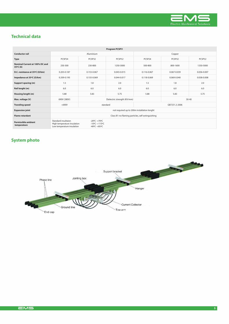
Technical data
System photo
Program PCSPI1
Conductor rail aluminium copper
Type PcsP24 PcsP32 PcsP52 PcsP24 PcsP32 PcsP52
Nominal Current at 100% DC and 35ºC (A) 250-300 230-800 1250-3000 500-800 800-1600 1250-5000
D.C. resistance at 35ºC (Ω/km) 0.203-0.187 0.153-0.067 0.043-0.015 0.116-0.067 0.067-0.039 0.036-0.007
Impedance at 35ºC (Ω/km) 0.209-0.195 0.155-0.069 0.044-0.017 0.118-0.069 0.069-0.040 0.038-0.008
Support spacing (m) 1.5 1.8 2.0 1.5 1.8 2.0
Rail lenght (m) 6.0 6.0 6.0 6.0 6.0 6.0
Housing length (m) 5.88 5.83 5.75 5.88 5.83 5.75
Max. voltage (V) 690V (380V) dielectric strength (KV/mm) 30-40
Traveling speed <690V standard GB7251.2-2006
Expansion joint not required up to 200m installation lenght
Flame retardant class B1-no flaming particles, self-extinguishing
Permissible ambient temperature
standard insultaion -20ºc- +70ºcHigh temperature insulation -10ºc- +115ºclow temperature insulation -40ºc- +85ºc
6
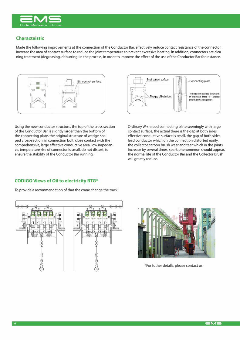
Characteistic
made the following improvements at the connection of the conductor Bar, effectively reduce contact resistance of the connector, increase the area of contact surface to reduce the joint temperature to prevent excessive heating, ln addition, connectors are clea-ning treatment (degreasing, deburring) in the process, in order to improve the effect of the use of the conductor Bar for instance.
using the new conductor structure, the top of the cross section of the conductor Bar is slightly larger than the bottom of the connecting plate, the original structure of wedge-sha-ped cross-section, in connection bolt, close contact with the comprehensive, large effective conductive area, low impedan-ce, temperature rise of connector is small, do not distort, to ensure the stability of the conductor Bar running.
ordinary W-shaped connecting plate seemingly with large contact surface, the actual there is the gap at both sides, effective conductive surface is small, the gap of both sides lead conductor which on the connection distorted easily, the collector carbon brush wear and tear which in the joints increase by several times, spark phenomenon should appear, the normal life of the conductor Bar and the collector Brush will greatly reduce.
CODIGO Views of Oil to electricity RTG*
*For futher details, please contact us.
to provide a recommendation of that the crane change the track.

7
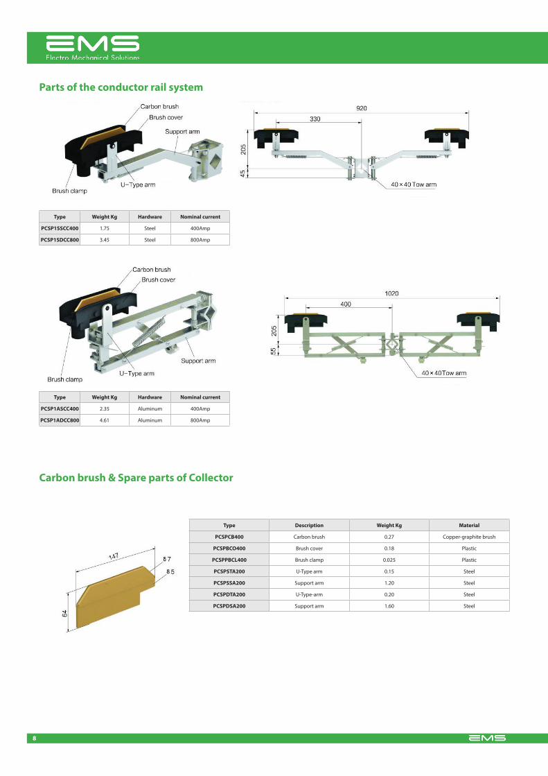
Parts of the conductor rail system
aluminium conductor
standard length: 6.0m
other lengths on request
support spacing: 1.8m or 2.0m
stainless steel belt
B=9.8mm
PCSP32 System
copper conductor
support spacing: 1.8m or 2.0m
standard length: 6.0m
other lengths on request
Type Conductor material Cross section (mm2) Nominal current (A) Leakage-distance (mm) Resistance (Ω/Km) Weight kg
PCSP13201I6PA aluminium 230 320 80 0.153 0.96
PCSP15001I6PA aluminium 285 500 80 0.116 1.13
PCSP16301I6PA aluminium 360 630 80 0.087 1.38
PCSP18001I6PA aluminium 450 800 80 0.067 1.50
PCSP110001I6PA aluminium 550 1000 80 0.058 1.83
PCSP112501I6PA aluminium 600 1250 80 0.046 2.01
the neutral insulation cover is marked yellow-green on one side.standard insulation suitable from -20ºc to +70ºc ambient temperature.High temperature insulation suitable from -10ºc to +115ºc ambient temperature.low temperature insulation suitable from -40ºc to +85ºc ambient temperature.
Type Conductor material Cross section (mm2) Nominal current (A) Leakage-distance (mm) Resistance (Ω/Km) Weight kg
PCSP18002I6PA copper 230 800 80 0.067 2.43
PCSP110002I6PA copper 300 1000 80 0.058 3.05
PCSP112502I6PA copper 360 1250 80 0.046 3.56
PCSP116002I6PA copper 450 1600 80 0.039 4.37
8
Type Weight Kg Hardware Nominal current
PCSP1SSCC400 1.75 steel 400amp
PCSP1SDCC800 3.45 steel 800amp
Type Weight Kg Hardware Nominal current
PCSP1ASCC400 2.35 aluminum 400amp
PCSP1ADCC800 4.61 aluminum 800amp
Type Description Weight Kg Material
PCSPCB400 carbon brush 0.27 copper-graphite brush
PCSPBCO400 Brush cover 0.18 Plastic
PCSPPBCL400 Brush clamp 0.025 Plastic
PCSPSTA200 u-type arm 0.15 steel
PCSPSSA200 support arm 1.20 steel
PCSPDTA200 u-type-arm 0.20 steel
PCSPDSA200 support arm 1.60 steel
Parts of the conductor rail system
Carbon brush & Spare parts of Collector

9
Type Weight Kg Hardware Nominal current
PCSP1ASCC500 3.05 aluminum 500amp
PCSP1ADCC1000 6.01 aluminum 1000amp
Carbon brush & Spare parts of Collector
Type Name Wight Kg Material
PCSP1CB500 carbon brush 0.73 cooper-graphite brush
PCSP1BCO500 Brush cover 0.30 Plastic
Tow arm
Type Weight Kg Material Length (mm)
PCSP1TA350A 1.00 steel 400
PCSP1TA400A 0.85 steel 350
PCSP1TA500A >1.00 steel 400
Parts of the conductor rail system

10
Hanger
Type Weight Kg Material
PCSP1AH68 0.085 Plastic
be used for high temperature
Joint Cap
Type Weight Kg Material
PCSP1JC44 0.21 Plastic
be used for high temperature
Jointsevery joint could be use for feeding joint.
Type Weight Kg Material
PCSP1AJ500 0.32 aluminium
PCSP1CJ800 0.41 copper
PCSP1AJ1000 0.40 aluminium
PCSP1CJ1250 0.66 copper
PCSP1CJ1600 0.82 copper
End cap
Type Weight Kg Material
PCSP1EC35 0.04 Plastic
Isolating Section
Type Weight Kg Material
PCSP1IS47 0.13 Plastic

11
Parts of the conductor rail system
aluminium conductor
standard length: 6.0m
other lengths on request
support spacing: 1.5m
curves
120mm.min.r=1.2m
stainless steel belt
B=8.5mm
PCSP24 System
copper conductor
standard length: 6.0m
support sºpacing: 1.5m
other lengths on request
Type Conductor material Cross section (mm2) Nominal current (A) Leakage-distance (mm) Resistance (Ω/Km) Weight kg
PCSP12501I6PA aluminium 160 250 45 or 80 0.203 0.63
PCSP13001I6PA aluminium 180 300 45 or 80 0.187 0.71
Type Conductor material Cross section (mm2) Nominal current (A) Leakage-distance (mm) Resistance (Ω/Km) Weight kg
PCSP15002I6PA copper 160 500 45 or 80 0.112 1.68
PCSP16002I6PA copper 180 600 45 or 80 0.098 1.86
PCSP17002I6PA copper 200 700 45 or 80 0.087 2.04
PCSP18002I6PA copper 230 800 45 or 80 0.076 2.30
the neutral insulation cover is marked yellow-green on one side.standard insulation suitable from -20ºc to +70ºc ambient temperature.High temperature insulation suitable from -10ºc to +115ºc ambient temperature.low temperature insulation suitable from -40ºc to +85ºc ambient temperature.

12
Type Weight Kg Hardware Nominal current
PCSP1SSCC200 1.45 Galvanized 200amp
PCSP1SDCC400 2.72 Galvanized 400amp
PCSP1ASCC200 1.18 aluminum 200amp
PCSP1ADCC400 2.25 aluminum 400amp
Be used for conductor rail codigo system
Carbon brush & Spare parts of Collector
Type Name Weight Kg Material
PCSPCB200 carbon brush 0.12 cooper-graphite brush
PCSPBCO200 Brush cover 0.09 Plastic
PCSPPBCL200 Brush clamp 0.015 Plastic
PCSPSTA200 u-type arm 0.095 steel
PCSPSSA200 support arm 1.20 steel
PCSPDTA200 u-type arm 0.13 steel
PCSPDSA200 support arm 1.10 steel
Parts of the conductor rail system

13
Hanger
Type Weight Kg Material
PCSP1AH55 0.04 Plastic
be used for high temperature
Jointing Cap
Type Weight Kg Material
PCSP1JC32 0.12 Plastic
be used for high temperature
Jointsevery joint could be use for feeding joint.
Type Weight Kg Material
PCSP1AJ250 0.15 aluminium
PCSP1CJ500 0.23 copper
PCSP1CJ800 0.31 copper
End cap
Type Weight Kg Material
PCSP1EC30 0.02 Plastic
Isolating Section
Type Weight Kg Material
PCSP1IS35 0.04 Plastic

14
aluminium conductor
stainless steel belt
B=16mm
standard length:6.0m.
other lengths on request
PCSP52 ystem
copper conductor
standard length: 6.0m
other lengths on request
Type Conductor material Cross section (mm2) Nominal current (A) Leakage-distance (mm) Resistance (Ω/Km) Weight kg
PCSP15001I6PA aluminium 900 1500 100 0.039 2.85
PCSP16001I6PA aluminium 1000 1600 100 0.037 3.25
PCSP20001I6PA aluminium 1350 2000 100 0.028 4.32
PCSP25001I6PA aluminium 1600 2500 100 0.018 4.99
PCSP30001I6PA aluminium 2000 3000 100 0.015 6.07
Type Conductor material Cross section (mm2) Nominal current (A) Leakage-distance (mm) Resistance (Ω/Km) Weight kg
PCSP16002I6PA copper 500 1600 100 0.036 5.12
PCSP120002I6PA copper 700 2000 100 0.026 6.91
PCSP125002I6PA copper 850 2500 100 0.018 8.25
PCSP130002I6PA copper 1000 3000 100 0.011 9.65
PCSP135002I6PA copper 1200 3500 100 0.009 11.42
PCSP145002I6PA copper 1600 4500 100 0.008 14.99
PCSP150002I6PA copper 1800 5000 100 0.007 16.75
the neutral insulation cover is marked yellow-green on one side.standard insulation suitable from -20ºc to +70ºc ambient temperature.High temperature insulation suitable from -10ºc to +115ºc ambient temperature.low temperature insulation suitable from -40ºc to +85ºc ambient temperature.
Parts of the conductor rail system

15
Be used conductor rail W52 system
Type Weight Kg Hardware Nominal current
PCSP1SSCC800 5.10 steel 800amp
PCSP1SDCC1600 10.20 steel 1600amp
Carbon brush & Spare parts of current Collector
Type Name Weight kg Material
PCSPCB800 carbon brush 1.20 carbon brush & Brass
PCSPBCO800 Brush cover 0.50 Plastic
PCSPSTA800 u-type am 0.50 steel
PCSPSSA800 support am 3.00 steel
PCSPDSA800 support am 1.50 aluminium
Parts of the conductor rail system
16
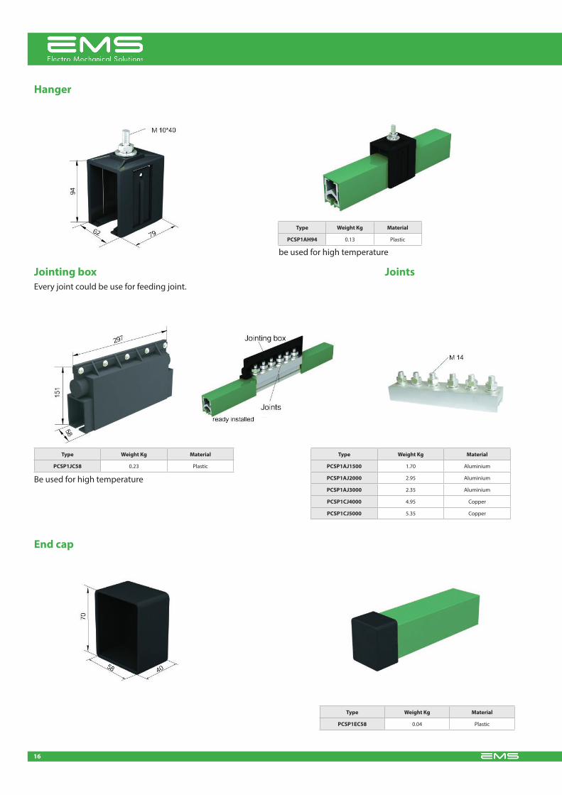
Hanger
Type Weight Kg Material
PCSP1AH94 0.13 Plastic
be used for high temperature
Jointing box
Type Weight Kg Material
PCSP1JC58 0.23 Plastic
Be used for high temperature
every joint could be use for feeding joint.
Type Weight Kg Material
PCSP1AJ1500 1.70 aluminium
PCSP1AJ2000 2.95 aluminium
PCSP1AJ3000 2.35 aluminium
PCSP1CJ4000 4.95 copper
PCSP1CJ5000 5.35 copper
End cap
Type Weight Kg Material
PCSP1EC58 0.04 Plastic
Joints

17
Type Conductor material
PCSP1AEJ250 al
PCSP1CEJ800 cu
PCSP1AEJ1000 al
PCSP1CEJ1600 cu
PCSP1AEJ3000 al
PCSP1CEJ5000 cu
Solution about expansion section
installation hint: the expansion joint section is supplied fully assembled in a 6 m length (W19 is 4.5 in length).With the exception of the rail connector installation no extra work is required on site. Please note, however, that the two air gaps in the expansion joint must be adjusted as pen diagram 1 corresponding to the ambient temperature during assembly. the air gaps must be rechecked after fitting the anchor damps. Both air gaps in an expansion joint must be identical.
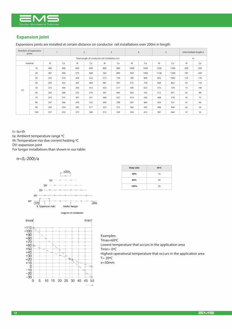
Expansion joint
18
expansions joints are installed at certain distance on conductor rail installations over 200m in length
numbers of expansions joints 1 2 3 4 5 intermediate length a
total length of conductor rail installation (m) m
material al cu al cu al cu al cu al cu al cu
tºc
10 400 400 600 600 800 800 1000 1000 1200 1200 200 200
20 387 400 575 600 762 800 950 1000 1138 1200 187 200
30 325 376 450 553 575 729 700 905 825 1082 125 176
40 293 332 387 464 481 597 575 729 669 862 93 132
50 275 306 350 412 425 517 500 623 575 729 75 106
60 262 288 325 376 387 464 450 553 512 641 62 88
70 253 275 307 351 360 427 414 502 468 578 53 75
80 247 266 294 332 340 398 387 464 434 531 47 66
90 242 259 283 317 325 375 366 435 408 494 42 59
100 237 253 275 306 312 359 350 412 387 464 37 53
t= ta+thta: ambient temperature range ºcth: temperature rise due corrent heating ºc dV: expansion jointFor longer installations than shown in our table:
n=(l-200)/a
Duty cicle thºC
40% 10
60% 20
100% 30
examples:tmax=60ºclowest temperature that occurs in the application areatmin= 0ºcHighest operational temperature that occurs in the application areat= 20ºcx=30mm
Expansion joint

19
installation manual: 1. support installation: Fix the two supports of both sides of the track (welding or bolt) and adjust to the horizontal state(add 1 or 2 points to meet the length of the wiring route).take the wiring between the two supports as the benchmark, the rest supports should be installed according to the standard distance(1800 mm for bolt and 2000 mm for welding), to ensure the depth of parallelism of the conductor rail between the height of the track less than 10 mm. 2. the connection part of the conductor and the connector should be polished with abrasive cloth to remove the oxide layer, apply the electrical conductive pastes and screw the bolt, double check if the seam of the guides is in minimum. 3. the installation of the current collector: define the length of the tow arm unit accor-ding to the poles of electrode and installation space. 120 ± 5mm distance should be ensured in distance between the upper end and down end of the conductor rail (refer to the installation drawing of the conductor rail for more details) 4. end cap: install the end caps on both sides and tighten them with rubberized fabric. 5. inspection: inspect the depth of parallelism between the conductor rail and operation track of the hoisting unit and control the depth within 20mm, make a test run and check the running state of the flake passing through each nodal point, tighten all the fastening piece if some problems occurs, dry run one month without interval and tighten all fastening pieces again.
Vertical operation of power rail (welding on angle steel bracket) Horizontal operation of power rail (welding on angle steel bracket)
System arrangement

www.ems-sl.com