EMERSON EMC PCM-18 WEB CONTROL APPLICATION MODULE OPERATORS MANUAL
PCM-17 APPLICATION MODULEOPERATORS MANUAL
SETUP AND PROGRAMMING
Emerson EMC1365 Park Road
Channhassen, MN 55317
Information furnished by EMERSON EMC is believed to be accurateand reliable. However, no responsibility is assumed by EMERSON EMCfor its use. EMERSON EMC reserves the right to change the design oroperation of the equipment described herein and any associated motionproducts without notice. EMERSON EMC also assumes no responsibilityfor any errors that may appear in this document. Information indocument is subject to change without notice.
P/N 400287-00 Rev: A1

Date: October 15, 1994

Customer Services
EMERSON EMC offers a wide range of services to support our customers' needs. Listed below are someexamples of these services.
Service Support (612)-474-8833
Emerson Electronic Motion Control's products are backed by a team of professionals who will serviceyour installation wherever it may be. Our customer service center in Minneapolis, Minnesota is ready tohelp you solve those occasional problems over the telephone. Our customer service center is available24 hours a day for emergency service to help speed any problem solving. Also, all hardware replacementparts, should they ever be needed, are available through our customer service organization. Needon-site help? Emerson EMC provides on-site service, in most cases, the next day. Just call EmersonEMC's customer service center when on-site service or maintenance is required.
Training Services (612)-474-1116
Emerson EMC maintains a highly trained staff of instructors to familiarize customers with EmersonEMC's products and their applications. A number of courses are offered, many of which can be taught inyourplant upon request.
Application Engineering
An experienced staff of factory application engineers provide complete customer support for tough orcomplex applications. Our engineers offer you a broad base of experience and knowledge of electronicmotion control applications.
TABLE OF CONTENTSPCM-17
1.1 PCM-17 MODULE OVERVIEW...................................................................... 11.1.1 BASIC OPERATION............................................................................ 1
1.2 SETUP AND PROGRAMMING ...................................................................... 41.2.1 MASTER AXIS SETUP........................................................................ 5
1.2.1.1 MASTER AXIS SCREEN DEFINITIONS..................... 51.2.2 MASTER CYCLE SETUP.................................................................... 9
1.2.2.1 MASTER CYCLE SCREEN DESCRIPTIONS............. 91.2.3 SETTING UP INFEED PARAMETERS.............................................. 11
1.2.3.1 INFEEDS SCREEN DESCRIPTIONS......................... 111.2.4 PCM-17 PROGRAM SETUP.............................................................. 141.2.5 INPUTS/OUTPUTS............................................................................. 15
1.2.5.1 INPUTS ........................................................................ 151.2.5.2 OUTPUTS .................................................................... 16
1.3 PCM-17 OPERATION.................................................................................... 181.3.1 START UP SEQUENCE #1................................................................ 181.3.2 START UP SEQUENCE #2................................................................ 181.3.3 PRODUCT SEPARATION.................................................................. 221.3.4 GATING............................................................................................... 231.3.5 MULTIPLE INFEED DRIVE SYSTEM................................................ 25
1PCM 17 MODULE SETUP
PCM-17 RANDOM INFEED CONTROLLER
1.1PCM-17 MODULE OVERVIEWThe PCM-17 module is designed to control a system where randomly introduced productsmust be accurately placed on a mechanism that runs a measurable repeating cycle .
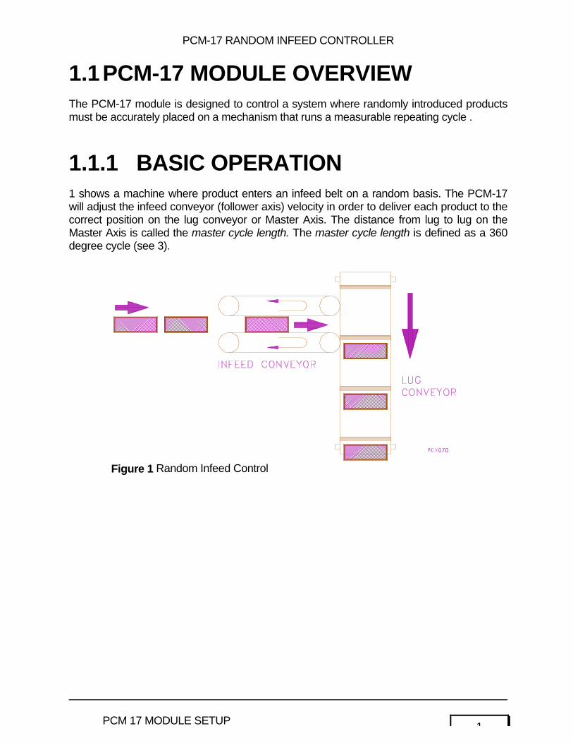
1.1.1 BASIC OPERATION1 shows a machine where product enters an infeed belt on a random basis. The PCM-17will adjust the infeed conveyor (follower axis) velocity in order to deliver each product to thecorrect position on the lug conveyor or Master Axis. The distance from lug to lug on theMaster Axis is called the master cycle length. The master cycle length is defined as a 360degree cycle (see 3).
Figure 1 Random Infeed Control

2 PCM 17 MODULE SETUP
3PCM 17 MODULE SETUP
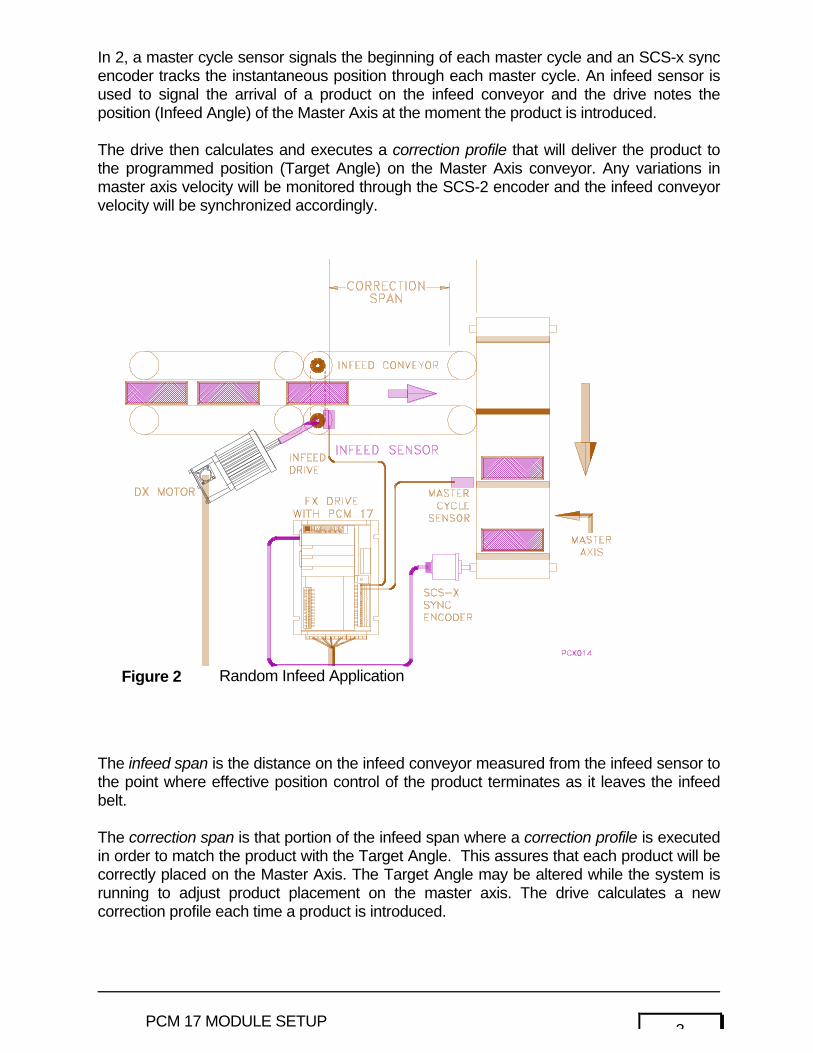
In 2, a master cycle sensor signals the beginning of each master cycle and an SCS-x syncencoder tracks the instantaneous position through each master cycle. An infeed sensor isused to signal the arrival of a product on the infeed conveyor and the drive notes theposition (Infeed Angle) of the Master Axis at the moment the product is introduced.
The drive then calculates and executes a correction profile that will deliver the product tothe programmed position (Target Angle) on the Master Axis conveyor. Any variations inmaster axis velocity will be monitored through the SCS-2 encoder and the infeed conveyorvelocity will be synchronized accordingly.
The infeed span is the distance on the infeed conveyor measured from the infeed sensor tothe point where effective position control of the product terminates as it leaves the infeedbelt.
The correction span is that portion of the infeed span where a correction profile is executedin order to match the product with the Target Angle. This assures that each product will becorrectly placed on the Master Axis. The Target Angle may be altered while the system isrunning to adjust product placement on the master axis. The drive calculates a newcorrection profile each time a product is introduced.
Figure 2 Random Infeed Application
4 PCM 17 MODULE SETUP
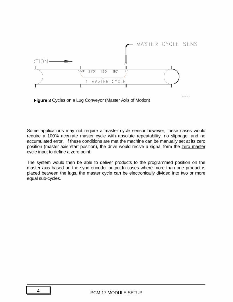
Some applications may not require a master cycle sensor however, these cases wouldrequire a 100% accurate master cycle with absolute repeatability, no slippage, and noaccumulated error. If these conditions are met the machine can be manually set at its zeroposition (master axis start position), the drive would recive a signal form the zero mastercycle input to define a zero point.
The system would then be able to deliver products to the programmed position on themaster axis based on the sync encoder output.In cases where more than one product isplaced between the lugs, the master cycle can be electronically divided into two or moreequal sub-cycles.
Figure 3 Cycles on a Lug Conveyor (Master Axis of Motion)
5PCM 17 MODULE SETUP
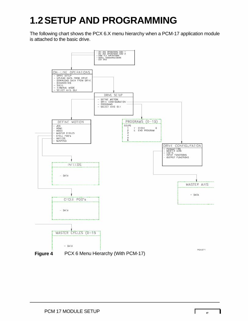
1.2SETUP AND PROGRAMMINGThe following chart shows the PCX 6.X menu hierarchy when a PCM-17 application moduleis attached to the basic drive.
Figure 4 PCX 6 Menu Hierarchy (With PCM-17)
6 PCM 17 MODULE SETUP
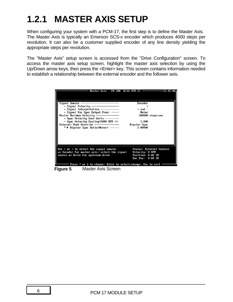
1.2.1 MASTER AXIS SETUPWhen configuring your system with a PCM-17, the first step is to define the Master Axis. The Master Axis is typically an Emerson SCS-x encoder which produces 4000 steps perrevolution. It can also be a customer supplied encoder of any line density yielding theappropriate steps per revolution.
The "Master Axis" setup screen is accessed from the "Drive Configuration" screen. Toaccess the master axis setup screen, highlight the master axis selection by using theUp/Down arrow keys, then press the <Enter> key. This screen contains information neededto establish a relationship between the external encoder and the follower axis.
Figure 5 Master Axis Screen
7PCM 17 MODULE SETUP
1.2.1.1 MASTER AXIS SCREENDEFINITIONS
Signal Source
Using the (+) or (-) keys to toggle between Drive and Encoder, the user selects theorigination of the signals used to determine the positional information of the Master Axis.
Signal Polarity
Defines the direction of the synchronization encoder that corresponds to a positivemaster position change. Clockwise is indicated with a (+), counterclockwise isindicated with a (-). Perspective is looking at the encoder shaft.

8 PCM 17 MODULE SETUP
Signal Interpretation
Use the arrow keys to toggle between the choices. The Signal Interpretation featureallows you to define how the follower reacts to clockwise and counterclockwisemotion of the synchronization encoder.
The following signal interpretation modes do not apply to the slip compensation or bipolarsync modes of operation. Signal interpretation modes apply only to ratio synchronization.
Mode #1 (+ and -): When the master axis moves either CW or CCW, the followeraxis will move in its commanded direction. If the master axischanges direction the follower axis will continue in the samecommanded direction. The follower axis will not reversedirection.
Mode #2 (+): The follower will only react to synchronization pulses when the masteraxis runs in the CW direction. CCW master axis pulses areignored.
Mode #3 (-): The follower will only react to synchronization pulses when themaster axis runs in the CCW direction. CW master axis pulsesare ignored.
Mode #4 (COMP +): The follower will only react to synchronization pulses when the masteraxis runs in the CW direction. The drive counts the pulsesreceived in the CCW direction and ignores that exact numberof CW pulses before follower motion in the CW directionoccurs. This feature compensates for master axis motion in theopposite (CCW) direction. For example, the master stops, theninadvertently backs up due to conveyor slack, etc.
Mode #5 (COMP -): The follower axis will only react to synchronization pulses when themaster axis runs in the CCW direction. The drive counts thepulses received in the CW direction and ignores that exactnumber of CCW pulses before follower motion in the CCWdirection occurs. This feature compensates for master axismotion in the opposite (CW) direction. For example, the masterstops, then inadvertently backs up due to conveyor slack, etc.
9PCM 17 MODULE SETUP
Signal For Sync Output From:
Use the arrow keys to toggle between the choices. If the user selects Motor, theamplifier will output a sync signal based on the performance of its own motor. If theuser selects Upstream Drive, the amplifier will output a signal that comes from themotor of the preceding amplifier.
Note: Encoder pulses are passed to all amplifiers in the synchronization chain. Theanswer to this question has no effect on the encoder signal.
Master Maximum Velocity
The Master Maximum Velocity is the maximum frequency that the Master Axis signalsource is expected to produce. To calculate the master maximum velocity use the followingformula:
Master Maximum Velocity (in steps per sec) =
Master's Drives Max Velocity (RPM) X Master Steps/Rev60 Second/Minutes
Master's Steps/Rev = Encoder Line Density X 4 (If Encoder is master)Master's Steps/Rev = 4096 (If Drive is Master)
Note: This value is the master encoder velocity at which synchronized time base andreal time base are equal. This parameter is used to calculate actual followervelocity while running in synchronized time base.
Sync Velocity User Units
Sets the units to be associated with all Sync velocities.
Sync Velocity Scaling (Max RPM Equals)
This parameter sets the sync velocity to equate to the maximum velocity of the drive.When an index is running in Sync Time Base the velocity is specified in user units(see Distance User Units in the Drive Parameters screen).
10 PCM 17 MODULE SETUP
External Mode Override
External mode override works in conjunction with input function #38 to override the currentmode of operation. When input function #38 is assigned and active the drive will exit it'scurrent operating mode and default to the mode selected with this parameter. Use thearrow keys to toggle between the three modes of operation which are Analog Velocity,Analog Torque or Bi-Polar Sync.
Analog Velocity/TorqueWhen set to analog velocity or torque mode, the drive will respond to aconventional ±10VDC signal. In either of the two analog modes of operation a ±10VDC signal is equated to either (CW) or (CCW) maximum programmed velocityor maximum full peak torque rating.
Bi-polar SyncWhen set to bi-polar sync, this parameter allows for bi-polar ratioing of the syncencoder to the drive motor.
Bi-polar Sync Ratio (motor)
The Bipolar Sync Ratio is the relationship of the Follower Axis position to theMaster axis position. If the Bipolar Sync Ratio is set to 3, for every 1 count ofthe Master Axis, there will be 3 counts of the Follower Axis. Thus, the BipolarSync Ratio would be 3:1. This ratio is used for Bipolar Sync mode.
11PCM 17 MODULE SETUP
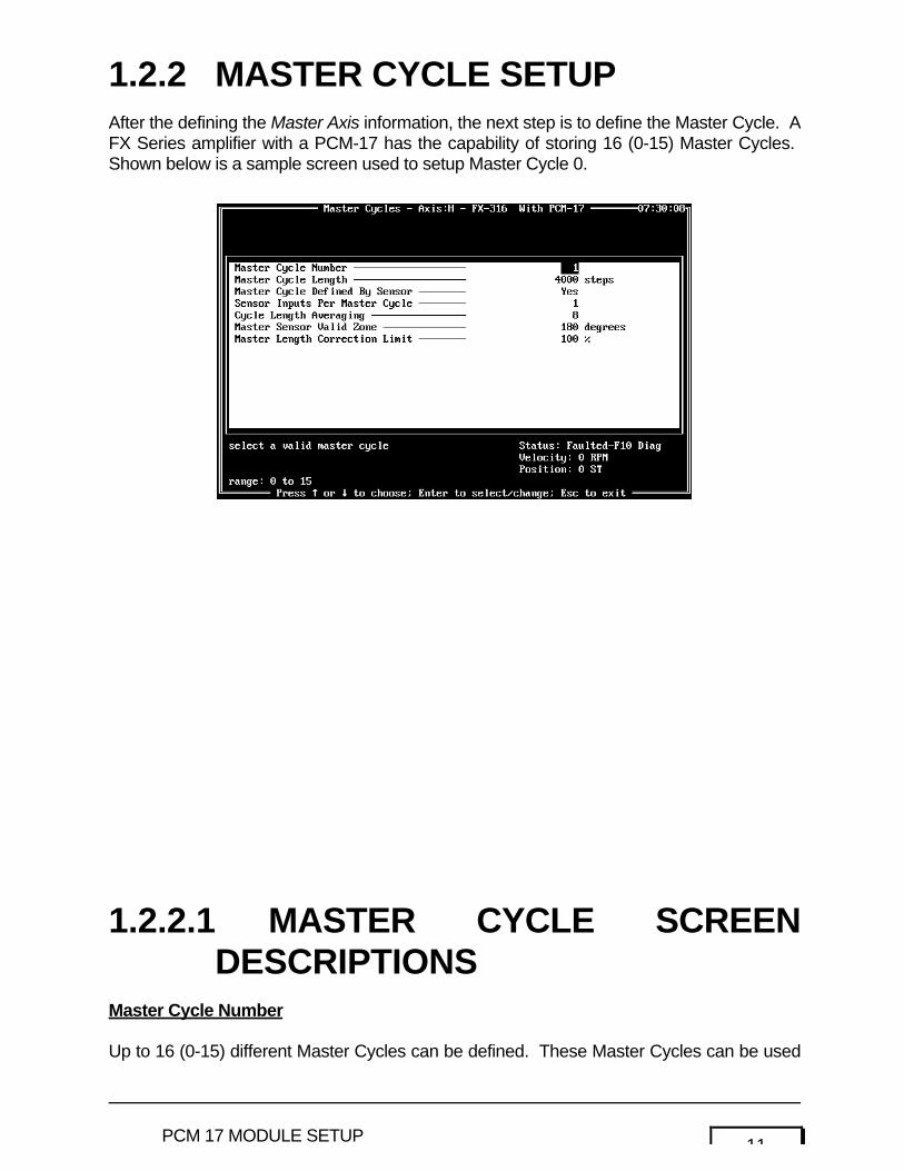
1.2.2 MASTER CYCLE SETUPAfter the defining the Master Axis information, the next step is to define the Master Cycle. AFX Series amplifier with a PCM-17 has the capability of storing 16 (0-15) Master Cycles. Shown below is a sample screen used to setup Master Cycle 0.
1.2.2.1 MASTER CYCLE SCREENDESCRIPTIONS
Master Cycle Number
Up to 16 (0-15) different Master Cycles can be defined. These Master Cycles can be used
12 PCM 17 MODULE SETUP
with any Infeed. In some processes only one Master Cycle is defined. This Master Cyclecan be used in conjunction with all 16 Infeeds.
Master Cycle Length
This entry defines the length of the Master Cycle in steps. This is the distance that amaster positioning drive, SCS-X encoder, or customer supplied encoder rotates througheach Master Cycle. This parameter is measured in steps.
NOTE: 1 revolution of SCS-X encoder = 4000 steps. 1 revolution of a masterpositioning amplifier = 4096. 1 revolution of a customer suppliedencoder is 4 * the encoder line count.

13PCM 17 MODULE SETUP
Master Cycle Defined by Sensor
This parameter defines how the master axis zero position (or start position) is defined. IfYES is entered, the zero degree position of the master axis is defined by the zero mastercycle sensor input line. If NO is entered, the zero degree position of the master axis will bedefined each time the number of steps entered in the master cycle length parameter iscounted by the master axis encoder.
Note: If NO is entered here, the last four master cycle parameters will not apply.
Sensor Inputs per Cycle
Allows the operator to vary the length of the cycle in terms of the number of sensor inputsrequired to measure one cycle i.e., 360° may equal one input or it may require the passingof 4 lugs (inputs) to complete one 360° cycle. This allows the Master Cycle to be dividedinto smaller sections. Two smaller divisions of the Master Cycle may not be greater than anequal number of steps per 1 Master Cycle.
Master Cycle Length Averaging
The amplifier will average the distance measured between successive Master CycleSensor input signals over a set number of cycles. For example, if (8) is entered for thevalue, the unit will average the last eight cycle length measurements to establish thecurrent cycle length. The current cycle length is then used to make any required phaseangle adjustment on the next cycle. This feature is employed to stabilize the measuredcycle length when minor variations in Master Cycle length occur.
Master Sensor Valid Zone
An area on both sides of the defined zero degree position in which a Zero Master CycleSensor input signal will be considered valid. For example; if the operator enters ±10° here,any input signal which appears on the Zero Master Cycle Sensor input which appearsbefore -10° or after +10° will be ignored. This is useful in applications where registrationmarks are printed in the same feed path as other printing (such as advertising, logos,instructions, etc.). The amplifier will ignore all inputs and outputs except those whichappear within the valid zone.
Master Length Correction Limit
This parameter limits the amount of correction made when master length error is detected. For example; if set ot 50%, the drive will use 50% of the error length to correct the masterlength.
14 PCM 17 MODULE SETUP
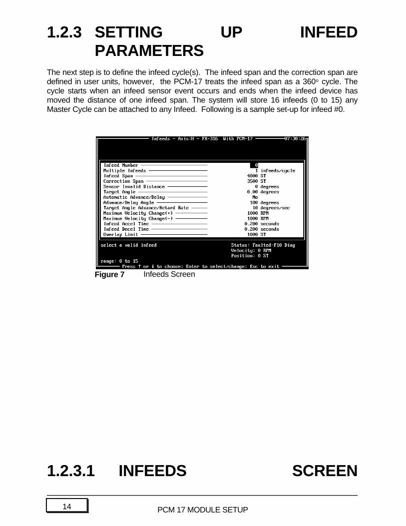
1.2.3 SETTING UP INFEEDPARAMETERS
The next step is to define the infeed cycle(s). The infeed span and the correction span aredefined in user units, however, the PCM-17 treats the infeed span as a 360° cycle. Thecycle starts when an infeed sensor event occurs and ends when the infeed device hasmoved the distance of one infeed span. The system will store 16 infeeds (0 to 15) anyMaster Cycle can be attached to any Infeed. Following is a sample set-up for infeed #0.
1.2.3.1 INFEEDS SCREEN
Figure 7 Infeeds Screen
15PCM 17 MODULE SETUP
DESCRIPTIONSInfeed Number
Each Infeed requires that a Master Cycle be attached. The same Master Cycle can beused for all 16 Infeeds.
Multiple Infeeds
This parameter allows the system to divide the Master Cycle into as many as 24 equalsubcycles. Each subcycle has its own zero point allowing the infeed controller to place asmany as 24 products into each Master Cycle.
Infeed Span
The Infeed Span is the distance (in user units) on the infeed conveyor measured fromwhere the infeed sensor detects an incoming product to where effective control of theproduct terminates as it leaves the infeed belt.
16 PCM 17 MODULE SETUP
Correction Span
The correction span is that portion of the infeed span where the correction profile isexecuted in order to place each product at the programmed Target Angle on the MasterAxis. The product must remain under control during execution of the entire correctionprofile.
Sensor Invalid Distance
Measured in degrees of the infeed cycle, this is a distance immediately following the initialinfeed sensor event during which any signal on the infeed sensor line will be ignored. Forexample: if this was an application where the product had through holes, several falsesensor events could occur after the initial sensor event . The system would respond only tothe initial signal and would ignore those inputs that occured in the invalid zone.
Target Angle
Measured in degrees of the Master Cycle, the Target Angle is the position on the MasterAxis where product is to be delivered. The position can be any value from 0 to 360 degrees,and may be altered while the amplifier is running. Changes can be made through the I/O,through a T-21, or through the use of ASCII commands. To view Target Angle changeswhile in PCX, exit from the Infeed screen and then re-enter.
Automatic Advance/Delay
If answered YES this feature will cause the system to attempt a positive correction profilewhenever possible. The drive calculations will include the Master Axis velocity. If the InfeedAngle is such that positive correction is not achievable then the drive will calculate anegative profile and the product will be delivered into the next Master Cycle. If answeredNO the drive will generate profiles based on the Advance/Delay Angle discussed below.
Advance/Delay Angle
Measured in degrees of the Master Axis, this position is essentially a decision point for thedrive. Any product whose Infeed Angle is less than this value will be given a positivecorrection profile, any product with an Infeed Angle that is greater will recieve a negativecorrection and will be placed in the next master cycle. The decision is based on position.
Target Angle Advance/Retard Rate
A signal on the Target Angle Advance or Retard Input will cause the programmed TargetAngle to change. This parameter establishes the rate at which this change occurs. It isdefined in degrees of the Master Axis.
17PCM 17 MODULE SETUP
Maximum Velocity Change (+)
Defines the maximum amount of velocity that can be added to the base ratio velocity in anyattempt to generate a positive correction profile.
Maximum Velocity Change (-)
Defines the maximum amount of velocity that can be subtracted from the base ratio velocityin any attempt to generate a negative correction profile.
Maximum Infeed Acceleration Rate
The acceleration rate employed any time an increase in the velocity of the infeed drive isrequired.
Maximum Infeed Deceleration
The deceleration rate employed any time a decrease in the velocity of the infeed drive isrequired.
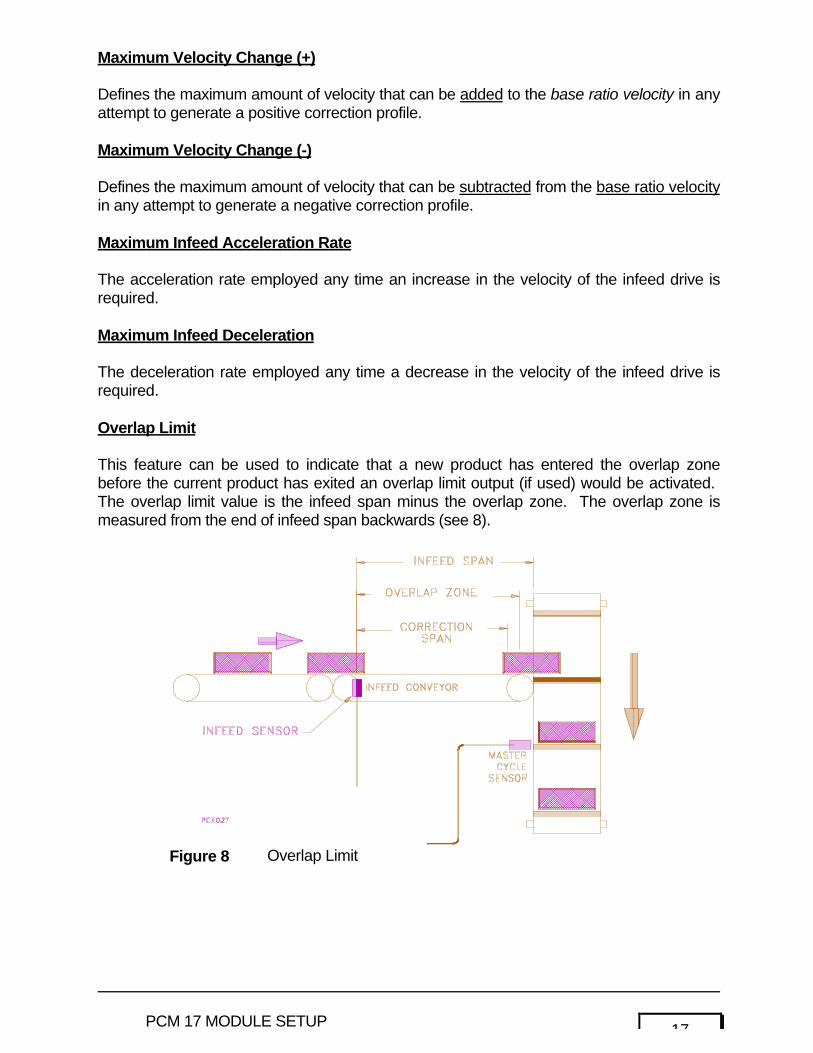
Overlap Limit
This feature can be used to indicate that a new product has entered the overlap zonebefore the current product has exited an overlap limit output (if used) would be activated. The overlap limit value is the infeed span minus the overlap zone. The overlap zone ismeasured from the end of infeed span backwards (see 8).
Figure 8 Overlap Limit
18 PCM 17 MODULE SETUP
Master Cycle Number
When the Infeed executes, this is the Master Cycle that will be used to determine where theproduct will be placed.
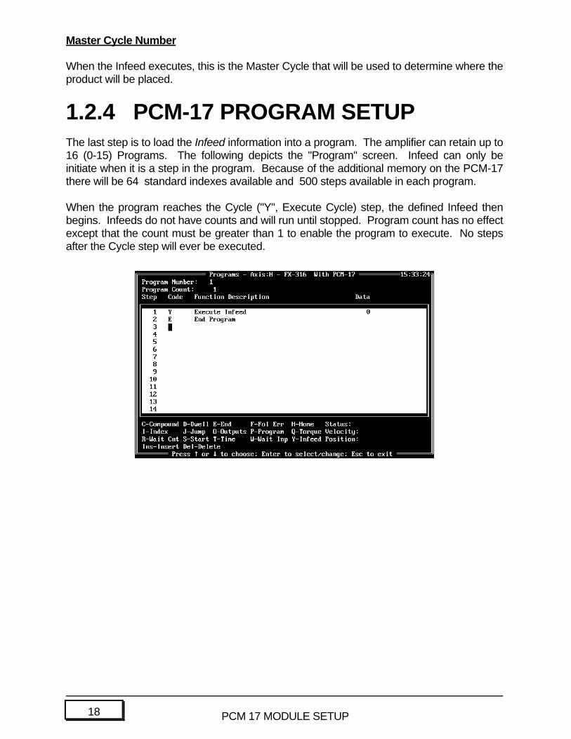
1.2.4 PCM-17 PROGRAM SETUPThe last step is to load the Infeed information into a program. The amplifier can retain up to16 (0-15) Programs. The following depicts the "Program" screen. Infeed can only beinitiate when it is a step in the program. Because of the additional memory on the PCM-17there will be 64 standard indexes available and 500 steps available in each program.
When the program reaches the Cycle ("Y", Execute Cycle) step, the defined Infeed thenbegins. Infeeds do not have counts and will run until stopped. Program count has no effectexcept that the count must be greater than 1 to enable the program to execute. No stepsafter the Cycle step will ever be executed.

19PCM 17 MODULE SETUP
1.2.5 INPUTS/OUTPUTSThe following logic control functions are added to the Input and Output screens any time aPCM-17 Module is employed.
1.2.5.1 INPUTS
FUNCTION# DESCRIPTION
45 Zero Master Cycle
Figure 10 Input Functions Screen
20 PCM 17 MODULE SETUP
Establishes master zero degree point each each cycle.
46 Infeed Sensor
Signals the drive that a product is entering the system.
47 Target Angle Advance
Target angle decreases at the programmed Target Angle or Advance/Retardrate.
48 Target Angle Retard
Target angle increases at the programmed Target Angle at theAdvance/Retard rate.
21PCM 17 MODULE SETUP
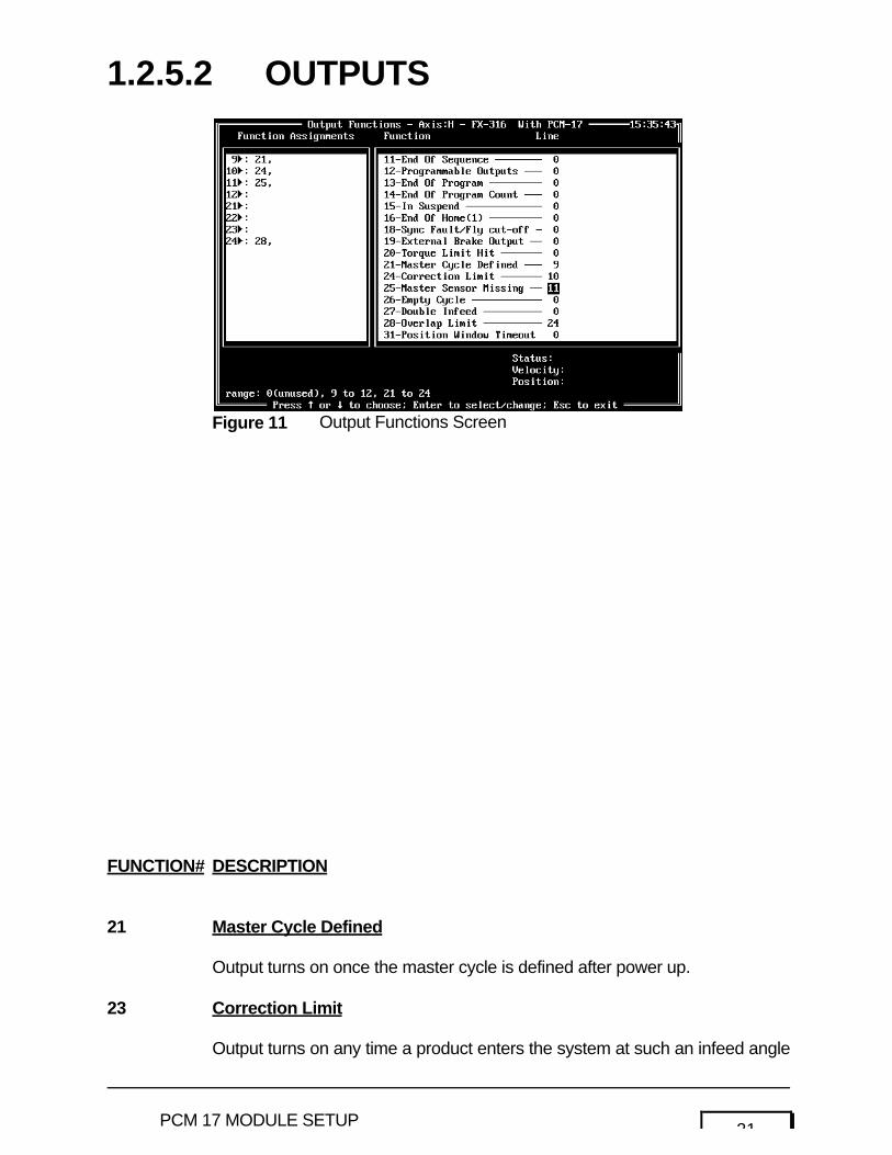
1.2.5.2 OUTPUTS
FUNCTION# DESCRIPTION
21 Master Cycle Defined
Output turns on once the master cycle is defined after power up.
23 Correction Limit
Output turns on any time a product enters the system at such an infeed angle
Figure 11 Output Functions Screen
22 PCM 17 MODULE SETUP
that the system cannot achieve the programmed target angle at the speedthat the Master Axis is running.
25 Master Cycle Missing
Output turns on once the master cycle sensor input fails to appear after amaster cycle distance is moved. The amount of distance after the expectedposition before the output comes on is programmed in dumb terminal modewith a default setting of 180°.
26 Empty Cycle
Output comes on any time a master cycle goes by without a product beinginserted.

23PCM 17 MODULE SETUP
27 Double Infeed
Output comes on any time a new product enters the correction span prior tothe time the previous product exits the correction span.
28 Overlap Limit
Output comes on any time a new product enters the overlap zone before thecurrent product has exited an overlap limit output (if used) would beactivated. The overlap limit value is the infeed span minus the overlap zone. The overlap zone is measured from the end of infeed span backwards (see 12).
Figure 12 Overlap Limit Output
24 PCM 17 MODULE SETUP
1.3PCM-17 OPERATION
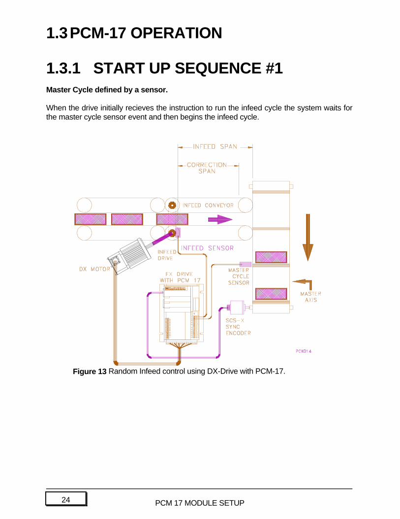
1.3.1 START UP SEQUENCE #1Master Cycle defined by a sensor.
When the drive initially recieves the instruction to run the infeed cycle the system waits forthe master cycle sensor event and then begins the infeed cycle.
Figure 13 Random Infeed control using DX-Drive with PCM-17.

25PCM 17 MODULE SETUP
1.3.2START UP SEQUENCE #2Master Cycle is NOT defined by a sensor.
when the drive recieves the infeed cycle instruction the system waits until a signal appearson the Zero Master Cycle input, and then proceeds to run the infeed cycle. This signalcould come from a PLC or a manual switch.

26 PCM 17 MODULE SETUP
Once the Master Axis Zero is established the system begins to run at a velocity that isratioed to the Master Axis. This is called the Base Ratio, and is derived at by the followingformula:
BASE RATIO = (INFEED SPAN in units) ÷÷ (MASTER CYCLE LENGTH in steps)
Upon receipt of the an Infeed Sensor signal the drive notes the Infeed Angle of the MasterAxis and compares it with the Target Angle. The drive calculates a Correction Profile whichcauses the product to move through the Infeed Span and match up with the Target Angle.This profile is added to the base ratio velocity and the Infeed delivers the product to theMaster.
The timing of the product entry determines the required amount of velocity change from thebase ratio. If the product frequency and timing are perfectly matched with the Master Cyclethen no velocity adjustments are required and the system runs at Base Ratio velocity. 14illustrates the relationship between Error Angle and Correction Profile velocities.
Figure 14 Correction Profile as a function of Error Angle

27PCM 17 MODULE SETUP
The correction profile is determined by the following formula:
Where τ = time duration of correction profileand _ = Error Angle (target angle minus infeed angle)
E o dµ ò t n t
28 PCM 17 MODULE SETUP
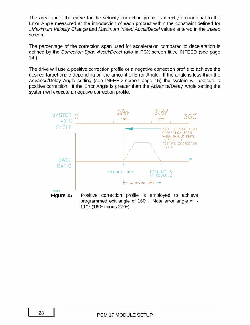
The area under the curve for the velocity correction profile is directly proportional to theError Angle measured at the introduction of each product within the constraint defined for±Maximum Velocity Change and Maximum Infeed Accel/Decel values entered in the Infeedscreen.
The percentage of the correction span used for acceleration compared to deceleration isdefined by the Correction Span Accel/Decel ratio in PCX screen titled INFEED (see page14 ).
The drive will use a positive correction profile or a negative correction profile to achieve thedesired target angle depending on the amount of Error Angle. If the angle is less than theAdvance/Delay Angle setting (see INFEED screen page 15) the system will execute apositive correction. If the Error Angle is greater than the Advance/Delay Angle setting thesystem will execute a negative correction profile.
Figure 15 Positive correction profile is employed to achieveprogrammed exit angle of 160°. Note error angle = -110° (160° minus 270°).

29PCM 17 MODULE SETUP
30 PCM 17 MODULE SETUP
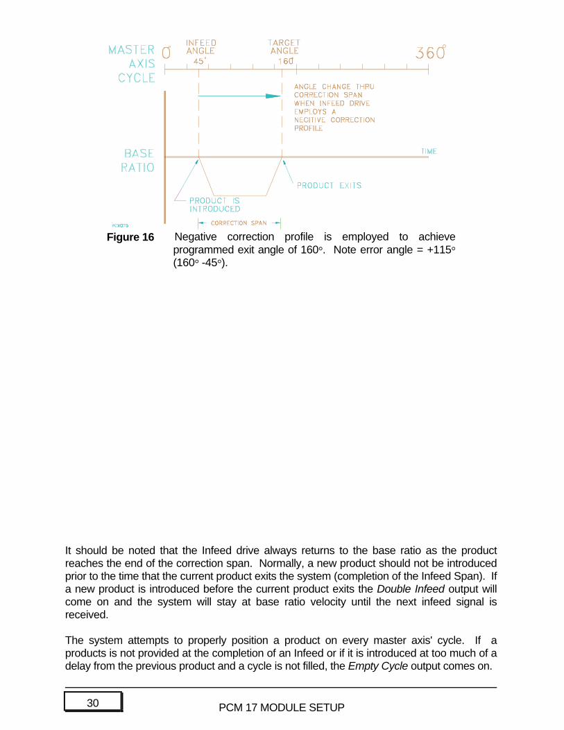
It should be noted that the Infeed drive always returns to the base ratio as the productreaches the end of the correction span. Normally, a new product should not be introducedprior to the time that the current product exits the system (completion of the Infeed Span). Ifa new product is introduced before the current product exits the Double Infeed output willcome on and the system will stay at base ratio velocity until the next infeed signal isreceived.
The system attempts to properly position a product on every master axis' cycle. If aproducts is not provided at the completion of an Infeed or if it is introduced at too much of adelay from the previous product and a cycle is not filled, the Empty Cycle output comes on.
Figure 16 Negative correction profile is employed to achieveprogrammed exit angle of 160°. Note error angle = +115°(160° -45°).
31PCM 17 MODULE SETUP
Depending on the speed of the master axis there may be some infeed angles at which nocorrection is possible. Any product introduced at such an angle will cause the CorrectionLimit Output to come on. This output will turn off at the completion of the current Infeedcycle.
32 PCM 17 MODULE SETUP
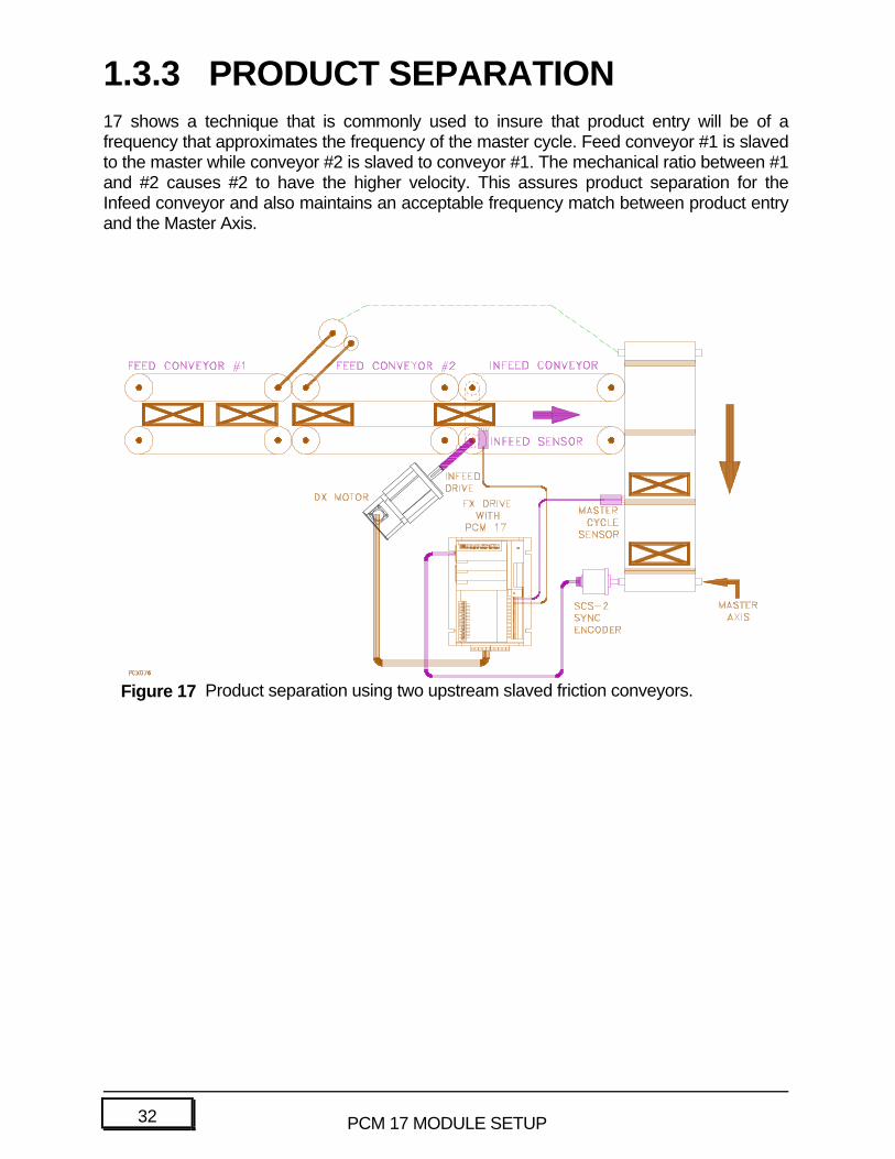
1.3.3 PRODUCT SEPARATION17 shows a technique that is commonly used to insure that product entry will be of afrequency that approximates the frequency of the master cycle. Feed conveyor #1 is slavedto the master while conveyor #2 is slaved to conveyor #1. The mechanical ratio between #1and #2 causes #2 to have the higher velocity. This assures product separation for theInfeed conveyor and also maintains an acceptable frequency match between product entryand the Master Axis.
Figure 17 Product separation using two upstream slaved friction conveyors.
33PCM 17 MODULE SETUP
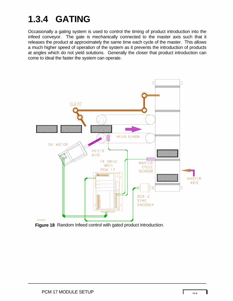
1.3.4 GATINGOccasionally a gating system is used to control the timing of product introduction into theinfeed conveyor. The gate is mechanically connected to the master axis such that itreleases the product at approximately the same time each cycle of the master. This allowsa much higher speed of operation of the system as it prevents the introduction of productsat angles which do not yield solutions. Generally the closer that product introduction cancome to ideal the faster the system can operate.
Figure 18 Random Infeed control with gated product introduction.

34 PCM 17 MODULE SETUP
35PCM 17 MODULE SETUP
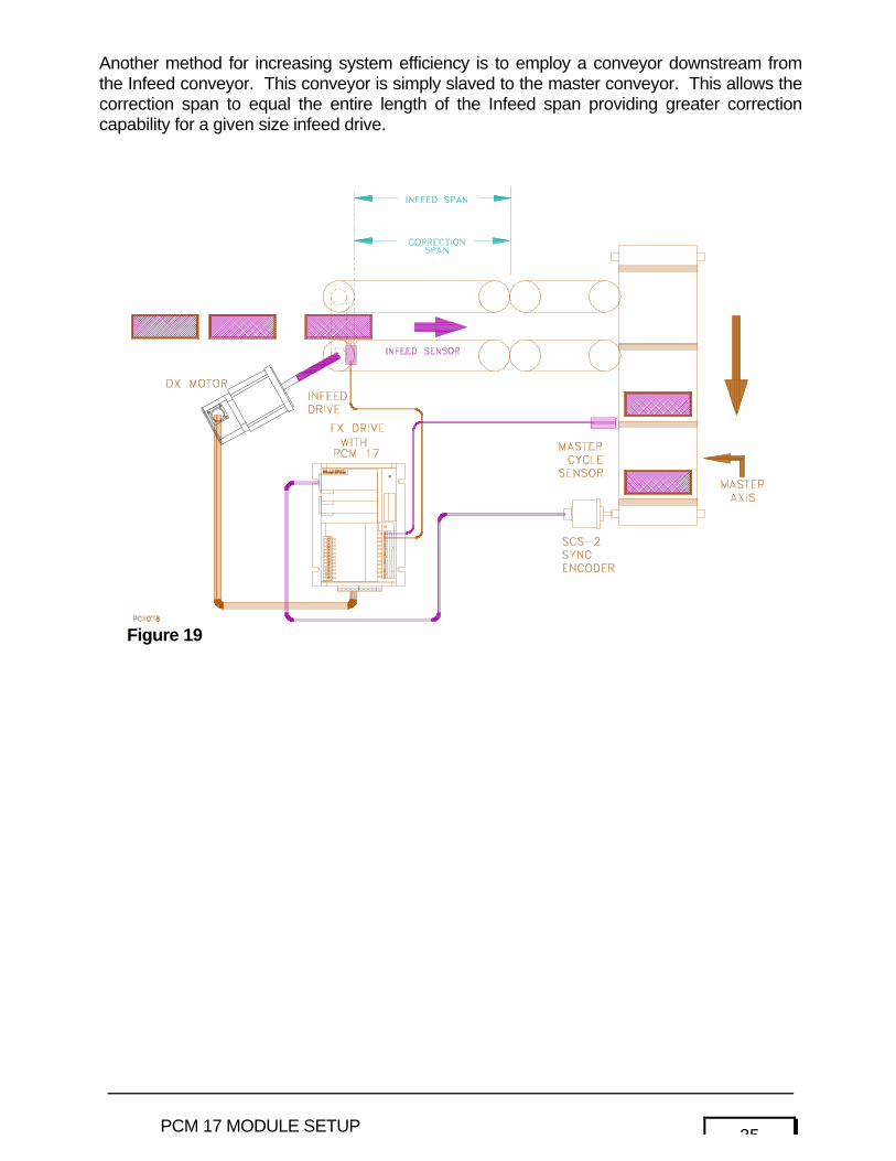
Another method for increasing system efficiency is to employ a conveyor downstream fromthe Infeed conveyor. This conveyor is simply slaved to the master conveyor. This allows thecorrection span to equal the entire length of the Infeed span providing greater correctioncapability for a given size infeed drive.
Figure 19
36 PCM 17 MODULE SETUP
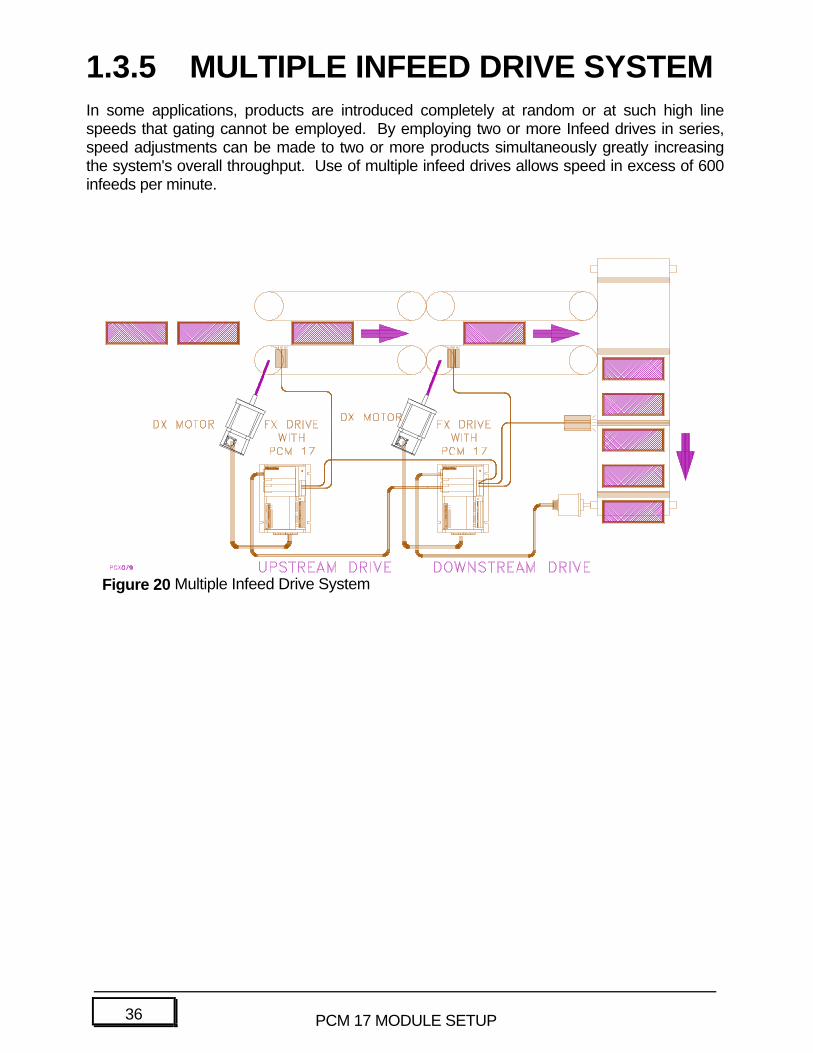
1.3.5 MULTIPLE INFEED DRIVE SYSTEMIn some applications, products are introduced completely at random or at such high linespeeds that gating cannot be employed. By employing two or more Infeed drives in series,speed adjustments can be made to two or more products simultaneously greatly increasingthe system's overall throughput. Use of multiple infeed drives allows speed in excess of 600infeeds per minute.
Figure 20 Multiple Infeed Drive System
37PCM 17 MODULE SETUP
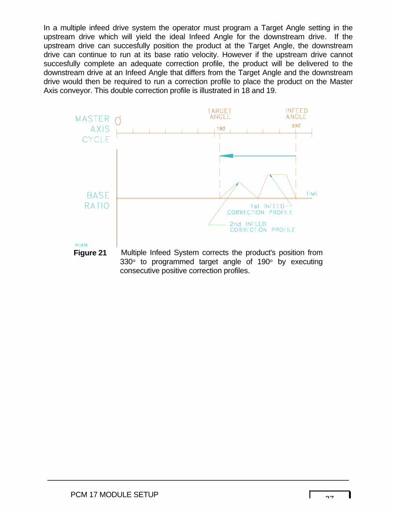
In a multiple infeed drive system the operator must program a Target Angle setting in theupstream drive which will yield the ideal Infeed Angle for the downstream drive. If theupstream drive can succesfully position the product at the Target Angle, the downstreamdrive can continue to run at its base ratio velocity. However if the upstream drive cannotsuccesfully complete an adequate correction profile, the product will be delivered to thedownstream drive at an Infeed Angle that differs from the Target Angle and the downstreamdrive would then be required to run a correction profile to place the product on the MasterAxis conveyor. This double correction profile is illustrated in 18 and 19.
Figure 21 Multiple Infeed System corrects the product's position from330° to programmed target angle of 190° by executingconsecutive positive correction profiles.
38 PCM 17 MODULE SETUP
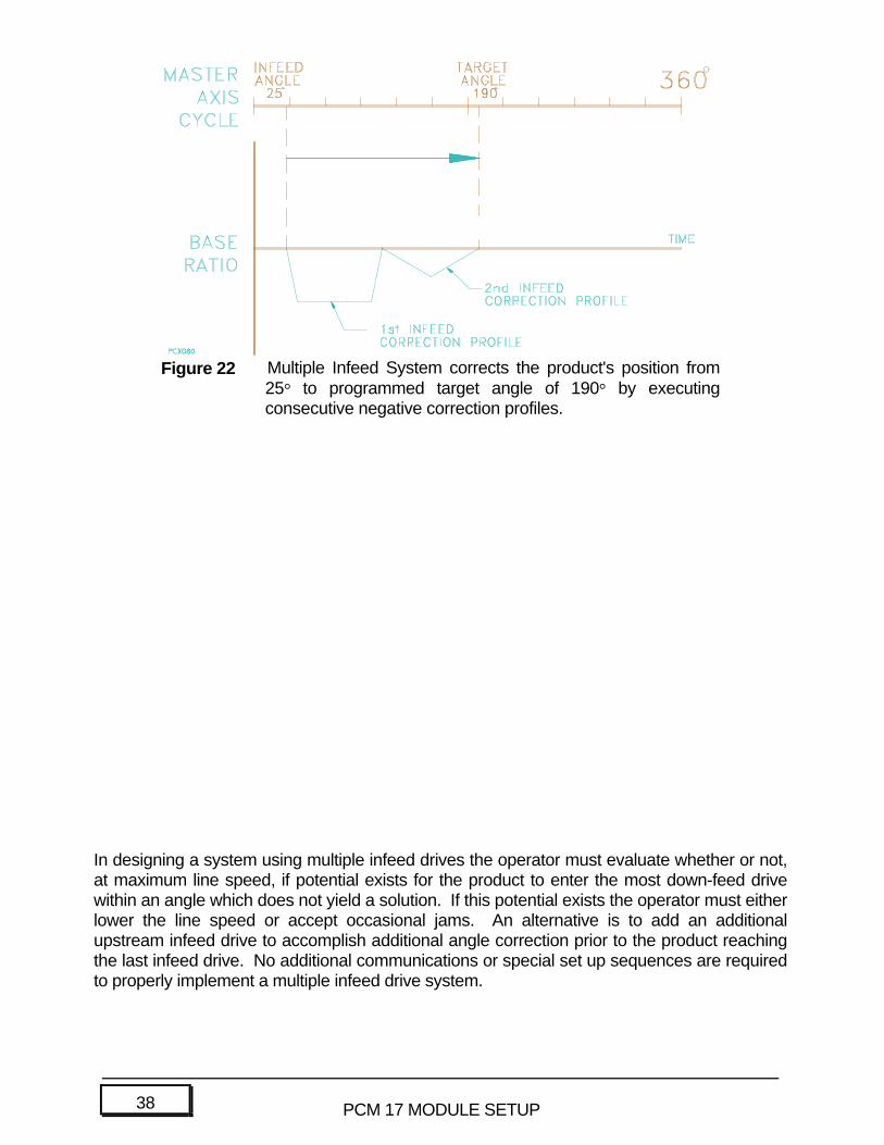
In designing a system using multiple infeed drives the operator must evaluate whether or not,at maximum line speed, if potential exists for the product to enter the most down-feed drivewithin an angle which does not yield a solution. If this potential exists the operator must eitherlower the line speed or accept occasional jams. An alternative is to add an additionalupstream infeed drive to accomplish additional angle correction prior to the product reachingthe last infeed drive. No additional communications or special set up sequences are requiredto properly implement a multiple infeed drive system.
Figure 22 Multiple Infeed System corrects the product's position from25° to programmed target angle of 190° by executingconsecutive negative correction profiles.
39PCM 17 MODULE SETUP
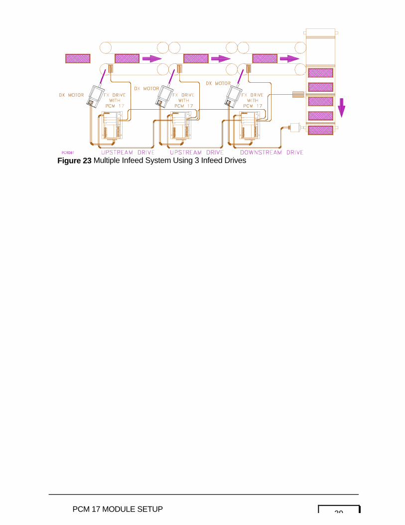
Figure 23 Multiple Infeed System Using 3 Infeed Drives

40 PCM 17 MODULE SETUP
Index
PCM-17Advance/Delay Angle........................................................................................................................... 12Analog Velocity/Torque......................................................................................................................... 8Automatic Advance/Delay .................................................................................................................. 12Base Ratio ............................................................................................................................................... 19Basic Operation ...................................................................................................................................... 1Bi-polar Sync ......................................................................................................................................... 8Bi-polar Sync Ratio (motor)................................................................................................................ 8Correction Limit Output...................................................................................................................... 16Correction Span .................................................................................................................................... 12Define Infeed Cycle(s).......................................................................................................................... 11Double Infeed Output ............................................................................................................................ 17Empty Cycle Output ............................................................................................................................. 16External Mode Override........................................................................................................................ 8Gating System.......................................................................................................................................... 23Infeed Number.......................................................................................................................................... 11Infeed Sensor Input................................................................................................................................ 15Infeed Span .............................................................................................................................................. 11Master Axis Setup................................................................................................................................... 5Master Cycle Not Defined By a Sensor ......................................................................................... 18Master Cycle Defined by Sensor...................................................................................................... 10Master Cycle Defined Output............................................................................................................ 16Master Cycle Length ............................................................................................................................. 9Master Cycle Length Averaging ....................................................................................................... 10Master Cycle Missing Output........................................................................................................... 16Master Cycle Number ...................................................................................................................... 9, 14Master Cycle Setup ............................................................................................................................... 9Master Maximum Velocity ..................................................................................................................... 7Master Sensor Valid Zone................................................................................................................... 10Maximum Infeed Acceleration Rate.................................................................................................... 13Maximum Infeed Deceleration.............................................................................................................. 13Maximum Velocity Change (+) .............................................................................................................. 13Maximum Velocity Change (-) .............................................................................................................. 13Multiple Infeed Drive System ............................................................................................................ 25Multiple Infeeds.................................................................................................................................... 11Overlap Limit ........................................................................................................................................ 13Overlap Limit Output .......................................................................................................................... 17Sensor Inputs per Cycle ..................................................................................................................... 10Sensor Invalid Distance ..................................................................................................................... 12Signal For Sync Output From: ............................................................................................................ 7Signal Interpretation ............................................................................................................................. 6Signal Polarity ...................................................................................................................................... 5Signal Source ........................................................................................................................................... 5Sync Velocity Scaling (Max RPM Equals)....................................................................................... 7Sync Velocity User Units...................................................................................................................... 7Target Angle............................................................................................................................................ 12Target Angle Advance Input................................................................................................................ 15Target Angle Advance/Retard Rate ................................................................................................... 12Target Angle Retard Input ................................................................................................................... 15Zero Master Cycle Input .................................................................................................................... 15