PCI-SIG ENGINEERING CHANGE NOTICE · 2015-11-10 · PCI-SIG ENGINEERING CHANGE NOTICE ......
34
Page 1 PCI-SIG ENGINEERING CHANGE NOTICE TITLE: Supporting PCIe and SATA BGA form factor for SSDs DATE: September 25, 2015 AFFECTED DOCUMENT: M.2 Spec Rev 1.0 SPONSOR: HP, Intel Corp., Lenovo, Micron, SanDisk, Seagate, Toshiba Part I 1. Summary of the Functional Changes This proposal is intended to define a new form-factor and electrical pinout to the M.2 family. This proposal will allow PCIe and SATA to be delivered using a BGA package, expanding the use of the PCIe and SATA protocols in small form-factor applications. The new BGA pinout content is based on the Socket 3 Key-M definitions. BGA pinout supports additional pins than defined for Socket-3, for soldered-down form- factors. 2. Benefits as a Result of the Changes Platform area savings (can benefit from increased battery size in turn), better thermals, lower z-height, support for lower signaling voltage (1.8 V, 1.2 V) aligning with industry current and future trends. Allows PCIe and SATA interface usage in small form-factor designs. 3. Assessment of the Impact Soldered-down ball-map definition will be added based on existing Socket 3 key-M signal definitions. Existing SSD Socket 2 and Socket 3 signal definitions will not be affected. BGA SSD supports industry standard IO signaling voltages of 1.8 V and futureproofing with 1.2 V. Connectorized modules need to implement voltage conversion/regulation from 3.3 V supply voltage to these lower IO signal voltages. The defined ball-map/pinouts will apply to soldered-down BGA SSDs. Component z-height options of S4 and S5 will be added to Socket 3 and SSD Socket 2. Connectorized module Type 2230 will also be added to Socket 3 options. 4. Analysis of the Hardware Implications New connectorized module sizes, BGA form-factor and footprints defined for soldered-down BGA SSD. 5. Analysis of the Software Implications N/A. 6. Analysis of the C&I Test Implications N/A.
Transcript of PCI-SIG ENGINEERING CHANGE NOTICE · 2015-11-10 · PCI-SIG ENGINEERING CHANGE NOTICE ......

Page 1
PCI-SIG ENGINEERING CHANGE NOTICE
TITLE: Supporting PCIe and SATA BGA form factor for SSDs
DATE: September 25, 2015
AFFECTED DOCUMENT: M.2 Spec Rev 1.0
SPONSOR: HP, Intel Corp., Lenovo, Micron, SanDisk, Seagate, Toshiba
Part I
1. Summary of the Functional Changes
This proposal is intended to define a new form-factor and electrical pinout to the M.2 family. This proposal will allow PCIe and SATA to be delivered using a BGA package, expanding the use of the PCIe and SATA protocols in small form-factor applications. The new BGA pinout content is based on the Socket 3 Key-M definitions. BGA pinout supports additional pins than defined for Socket-3, for soldered-down form-factors.
2. Benefits as a Result of the Changes
Platform area savings (can benefit from increased battery size in turn), better thermals, lower z-height, support for lower signaling voltage (1.8 V, 1.2 V) aligning with industry current and future trends. Allows PCIe and SATA interface usage in small form-factor designs.
3. Assessment of the Impact
Soldered-down ball-map definition will be added based on existing Socket 3 key-M signal definitions. Existing SSD Socket 2 and Socket 3 signal definitions will not be affected. BGA SSD supports industry standard IO signaling voltages of 1.8 V and futureproofing with 1.2 V. Connectorized modules need to implement voltage conversion/regulation from 3.3 V supply voltage to these lower IO signal voltages. The defined ball-map/pinouts will apply to soldered-down BGA SSDs. Component z-height options of S4 and S5 will be added to Socket 3 and SSD Socket 2. Connectorized module Type 2230 will also be added to Socket 3 options.
4. Analysis of the Hardware Implications
New connectorized module sizes, BGA form-factor and footprints defined for soldered-down BGA SSD.
5. Analysis of the Software Implications
N/A.
6. Analysis of the C&I Test Implications
N/A.

Page 2
Part II
Detailed Description of the change
Update section 1.3 as below:
HSIC - High-Speed Inter-Chip USB Electrical Specification, Version 1.0 (September 23, 2007), plus HSIC ECN Disconnect Supplement to High Speed Inter Chip Specification Revision 0.94 (Sep 20, 2012)
USB2.0 - Universal Serial Bus Specification, Revision 2.0, plus ECN and Errata, July 14, 2011, available from usb.org
USB3.0 - Universal Serial Bus 3.0 Specification, Revision 1 plus ECN and Errata, July 29 2011, available from usb.org
DisplayPort Standard Specifications, version 1.2
Serial ATA Revision 3.2 Gold or later, available from sata-io.org
I2C BUS Specifications, Version 2.1, January 2000
EIA-364 Electrical Connector/Socket Test Procedures including Environmental Classifications
EIA-364-1000.01: Environmental Test Methodology for Assessing the Performance of Electrical Connectors and Sockets Used in Business Office Applications
JTAG specification (IEEE 1149.1), available from ieee.org
System Management Bus (SMBus) Specification, Version 2.0, August 3, 2000, available from smbus.org

Page 3
Change Section 2.1 as follows to include BGA sizes:
2.1 Overview
This specification defines a family of M.2 modules and the corresponding system interconnects based on a 75 position edge card connection scheme or a derivation of the card edge and a soldered-down scheme for system interfaces.
The M.2 family comprised of several module sizes and designated by the following names (see Figure 2):
Type 1216
Type 1620
Type 1630
Type 2024
Type 2226
Type 2228
Type 2230
Type 2242
Type 2260
Type 2280
Type 2828
Type 3026
Type 3030
Type 3042
Type 22110

Page 4
Update Figure 2 and the subsequent text as shown below:
Figure 2. M.2 Family of Form Factors
The majority of M.2 types are connectorized using an edge connection scheme that can be either a single-sided or dual-sided assembly. There will be several component Z-height options defined in this specification. The type of edge connector will cater to different platform Z-height requirements. In all cases, the board thickness is 0.8 mm ±10%. The Type 1216, Type 2226, and Type 3026 are unique as they are soldered down solutions that will have an LGA pattern on the back. Therefore, they can only be single-sided and the board thickness does not need to adhere to the 0.8 mm ±10% requirement. The Type 1620, Type 2024, Type 2228 and Type 2828 are soldered-down solutions that have BGA pattern on the back and are defined for BGA SSDs. These BGA solutions can be placed directly on host platforms as standalone BGA SSDs, for which section 3.4 defines the interface specification. Some BGA types can also be mounted on SSD Socket 2 or SSD Socket 3 modules, for which sections 3.2 and 3.3 define interface specification. When a BGA SSD is mounted on SSD Socket 2 or SSD Socket 3 modules, the module is responsible for implementing the voltage conversion circuitry to provide 1.8 V and 1.2 V as required.

Page 5
The edge connector requires a mechanical key for accurate alignment. The location of the mechanical key along the Gold Finger contacts will make each key unique per a given socket connector. This prevents wrongful insertion of an incompatible board which prevents a safety hazard.
The board type, the type of assembly, the component Z-heights on top and bottom, and the mechanical key will make up the M.2 board naming convention detailed in the next section.
Update section 2.2 as follows:
2.2 Module Naming Convention
Because there are various types of M.2 solutions and configurations, a standard naming convention will be employed to define the main features of a specific solution.
The naming convention will identify the following:
The module size (width & length)
The component assembly maximum Z-height for the top and bottom sides of the module
The Mechanical Connector Key/Module key location/assignment or multiple locations/assignments
These naming conventions will clearly define the module functionality, what connector it coincides with, and what Z-heights are met. Figure 3 diagrams the naming convention.
The module width options are: 12 mm, 16 mm, 16.5 mm, 20 mm, 22 mm, 28 mm, and 30 mm.
The module length can scale to various lengths to support the content and expand as the content increases. The lengths supported are: 16 mm, 20 mm, 24 mm, 26 mm, 28 mm, 30 mm, 42 mm, 60 mm, 80 mm, and 110 mm.
Together these two dimensions make up the first part of the module type definition portion of the module name.
The next part of the name describes whether the module is single-sided or dual-sided and a secondary definition of what are the maximum Z-heights of the components on the top and bottom side of the module. Here we have specific Z-height limits that are either 2.0 mm, 1.75 mm, 1.5 mm, 1.35 mm, or 1.2 mm on the top side and 1.5mm, 1.35 mm, 0.7 mm and 0 mm on the bottom side. The letter S will designate Single-sided and the letter D will designate Dual-sided. This will be complimented with a number that designates the specific Z-height combination option.
The last section of the name will designate the mechanical connector key/module key name and the coinciding pin location. These will be designated by a letter from A to M. In cases where the module will have a dual key scheme to enable insertion of the module into two different keyed sockets, a second letter will be added to designate the second mechanical connector key/module key.
Key ID assignment must be approved by the PCI-SIG. Unauthorized Key IDs would render the modules incompatible with the M.2 specification.
Figure 4 on the following page shows an example of module Type 2242 – D2 – B – M.

Page 6
Update Figure-3 as follows:
Use ONLY when a double slot is being specified
Label included in height dimension
Key G is intended for custom use. Devices with this key will not be M.2-compliant. Use at your own risk!
Insulating label allowed on connector-based designs (1) For BGA SSD, Max Ht is measured with solder balls collapsed and is valid whether BGA is located directly
on a platform or mounted on a module board.

Page 7
Update Table 1 and preceding text as follows:
The board is 22 mm x 42 mm, Double Sided with a maximum Z-height of 1.35 mm on both the Top and Bottom, and it has two mechanical connector keys/module keys at locations B and M which will enable it to plug into two types of connectors (Key B or Key M).
Table 1 shows the various options for board configurations as a function of the Socket, Module Function and Module size.
Type 1216, Type 1620, Type 2024, Type 2226, Type 2228, Type 2828 and Type 3026 are unique as they are Soldered-Down solutions while all the others are connectorized with a PCB Gold Finger layout that coincides with an Edge Card connector. The Soldered-Down solutions do not have mechanical keys and their pin-out configuration needs to be specifically called out.
Table 1. Optional Module Configurations
Move Type 2230 specification (Section 2.3.3) and merge with section 2.3.4 Card Form Factors
for SSD Socket 2 and 3
TypeModule Height
Options
Pinout
Key
Connector
KeyType Module Height Options
Module
Key
1216 S1, S3 E N/A N/A N/A N/A
N/A N/A N/A A, E 1630 S1, D1, S3, D3, D4 A, E, A+E
2226 S1, S3 E A, E 2230 S1, D1, S3, D3, D4 A, E, A+E
3026 S1, S3 A+E A, E 3030 S1, D1, S3, D3, D4 A, E, A+E
Socket 2
WWAN/OtherN/A N/A N/A B 3042 S1, D1, S3, D3, D4 B
N/A N/A N/A B 2230 S2, D2, S3, D3, D5, S4, S5 B+M
N/A N/A N/A B 2242 S2, D2, S3, D3, D5, S4, S5 B+M
N/A N/A N/A B 2260 S2, D2, S3, D3, D5, S4, S5 B+M
N/A N/A N/A B 2280 S2, D2, S3, D3, D5, S4, S5 B+M
N/A N/A N/A B 22110 S2, D2, S3, D3, D5, S4, S5 B+M
1620 S1, S2, S3, S4, S5 N/A N/A N/A N/A N/A
2024 S1, S2, S3, S4, S5 N/A N/A N/A N/A N/A
2228 S1, S2, S3, S4, S5 N/A N/A N/A N/A N/A
2828 S1, S2, S3, S4, S5 N/A N/A N/A N/A N/AN/A
N/A N/A N/A M 2230 S2, D2, S3, D3, D5, S4, S5 M, B+M
N/A N/A N/A M 2242 S2, D2, S3, D3, D5, S4, S5 M, B+M
N/A N/A N/A M 2260 S2, D2, S3, D3, D5, S4, S5 M, B+M
N/A N/A N/A M 2280 S2, D2, S3, D3, D5, S4, S5 M, B+M
N/A N/A N/A M 22110 S2, D2, S3, D3, D5, S4, S5 M, B+M
1620 S1, S2, S3, S4, S5 N/A N/A N/A N/A N/A
2024 S1, S2, S3, S4, S5 N/A N/A N/A N/A N/A
2228 S1, S2, S3, S4, S5 N/A N/A N/A N/A N/A
2828 S1, S2, S3, S4, S5 N/A N/A N/A N/A N/A
Soldered Down Connectorized
Socket 1
Connectivity
Socket 2
SSD/Other
Socket 3
SSD Drive

Page 8
2.3.3 Card Form Factors for SSD Socket 2 and 3
2.3.3.1 Type 2230 Specification
Type 2230 is a M.2 board/module size used on Socket 2 and Socket 3. It is intended to support SSD solutions and possibly other PCI Express based solutions. The board is comprised of two sections:
Host I/F section Active Component section
The active component section including the mounting hole area has an overall length of 26 mm top side and 24.8 mm bottom side when applicable. Figure 10 shows Type 2230 board/module mechanical outline drawing.
22±0.15
(11)
30±0.15
4 MIN 5.20 MIN
1.35 MAX
TYPE 2230-D2-B 1.35 MAX
TOP SIDECOMPONENT
AREA
BOTTOM SIDE
COMPONENTAREA
TOP VIEW BOTTOM VIEWFOR CARD EDGE DETAIL SEESECTION 2.3.5
TOP
SIDE
BOTTOM
SIDE
MECHANICALGROUND PAD
MECHANICALGROUND PAD
22±0.15
(11)
30±0.15
4 MIN
1.35 MAX
TYPE 2230-S2-B
TOP VIEW
TOP
SIDE
BOTTOM
SIDE
BOTTOM VIEW
MECHANICALGROUND PAD
MECHANICALGROUND PAD
FOR CARD EDGE DETAIL SEESECTION 2.3.5
TOP SIDECOMPONENT
AREA
Figure 1. M.2 Type 2230-S2/D2 Mechanical Outline Diagram Examples

Page 9
Add following sections:
2.3.7 Soldered-Down Form Factors for BGA SSDs
Following different sizes are defined for the soldered-down BGA SSDs:
Type 1620
Type 2024
Type 2228
Type 2828
All these types are soldered-down and single sided. They have a BGA land pattern on the backside.
To help prevent module-warp, it is recommended to balance the copper area of the PCB layers. The guideline recommendation is for the difference between copper area of mirrored layers (for example, outer to outer layer, first inner on top to first inner on bottom, etc.) to be equal to or less than 15%.
The target differential impedance of the PCIe and SATA signals on the package is 85Ω. Differential coupling from other signals must be reduced to ensure signal integrity of the differential pair.
2.3.7.1 Type 1620 Specification
BGA package sizes of 2024, 2228 and 2828 contain the common core ball map of Type 1620. The larger packages of Type 2024, Type 2228 and Type 2828 have retention balls in addition to the core Type 1620 ball map.
Figure a shows the mechanical outline drawing for BGA Type 1620.

Page 10
Figure a: M.2 Type 1620-S5 Mechanical Outline Drawing Example

Page 11
Figure b shows a recommended land pattern for Type 1620 package. The dimensions shown in Figure b are nominal.
Figure b: Recommended Land Pattern for M.2 Type 1620 BGA (Top View)

Page 12
2.3.7.2 Type 2024 Specification
Figure c: M.2 Type 2024-S5 Mechanical Outline Drawing Example

Page 13
Figure d shows a recommended land pattern for Type 2024 package. The dimensions shown in Figure d are nominal.
Figure d: Recommended Land Pattern for M.2 Type 2024 BGA (Top View)

Page 14
2.3.7.3 Type 2228 Specification
Figure e: M.2 Type 2228-S5 Mechanical Outline Drawing Example

Page 15
Figure f shows a recommended land pattern for Type 2228 package. The dimensions shown in Figure f are nominal.
Figure f: Recommended Land Pattern for M.2 Type 2228 BGA (Top View)
Page 16
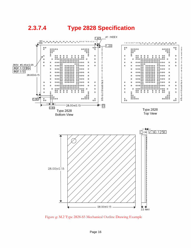
2.3.7.4 Type 2828 Specification
Figure g: M.2 Type 2828-S5 Mechanical Outline Drawing Example

Page 17
Figure h shows a recommended land pattern for Type 2828 package. The dimensions shown in Figure h are nominal.
Figure h: Recommended Land Pattern for M.2 Type 2828 BGA (Top View)
Update heading of section 2.3.7 RF Connectors to 2.3.8
2.3.8 RF Connectors

Page 18
Update Table 16 as follows:
Table 2. Power-Up CLKREQ# Timings
Symbol Parameter Min Max Units
TPVCRL Power Valid* to CLKREQ# Output active 100 µs
TPVPGL Power Valid* to PERST# Input inactive 1 ms
TPERST#-CLK REFCLK stable before PERST# inactive 100 µs
Note: *Power is valid when all the voltage supply rails have reached their respective Vmin.
3.1.3.2.2 Dynamic Clock Control
After a PCI Express device has powered up and whenever its upstream link enters the L1 link state, it shall allow its reference clock to be turned off (put into the parked clock state). To accomplish this, the device de-asserts CLKREQ# (high) and must allow that the reference clock will transition to the parked clock state within a delay (TCRHoff). Figure 80 shows the CLKREQ# clock control timing diagram.

Page 19
Add Section 3.4 and Table 34:
3.4. BGA SSD Interface Signals Table 34 contains a list of the signals defined for BGA SSDs. The I/O direction indicated is from BGA module’s perspective.
Table 34. BGA SSD System Interface Signal Table
Interface Signal Name I/O Function Voltage
Power and Grounds
+3.3 V (8 pins) I 3.3 V source 3.3 V
+1.8 V (12 pins) I 1.8 V source 1.8 V
+1.2 V (12 pins) I 1.2 V source 1.2 V
GND (104 pins) Return current path 0 V
PCIe PERp0, PERn0/ PETp0, PETn0
PERp1, PERn1/ PETp1, PETn1
PERp2, PERn2/ PETp2, PETn2
PERp3, PERn3/ PETp3, PETn3
I/O PCIe TX/RX Differential signals defined by the PCIe 3.0 specification.
REFCLKp/ REFCLKn I PCIe Reference Clock signals (100 MHz) defined by the PCIe 3.0 specification.
Note: This reference clock is the common ref clock that shall be used with PCIe.
PERST# I PE-Reset is a functional reset to the card as defined by the PCIe Mini CEM specification.
1.8 V
CLKREQ# I/O Clock Request is a reference clock request signal as defined by the PCIe Mini CEM specification; Also used by L1 PM Substates.
1.8 V
PEWAKE#/OBFF I/O PCIe WAKE#. Open Drain with pull up on platform. Active Low when used as PEWAKE#. When the add-in module supports wakeup, this signal is used to request that the system return from a sleep/suspend state to service a function initiated wake event. When the add-in module supports OBFF mechanism, the signal is used by the system to indicate OBFF or CPU Active State transitions.
1.8 V

Page 20
SATA SATA-A+, SATA-A-/
SATA-B+, SATA-B-
I/O Refer to Serial ATA specifications.
DEVSLP I
DAS/DSS# I/O
SSD Specific Signals
SUSCLK I 32.768 kHz clock supply input provided by the platform chipset to reduce power and cost for the module. SUSCLK will have a duty cycle that can be as low as 30% or as high as 70%. The tolerance for this clock is ±100 ppm.
1.8 V
PEDET O Host I/F Indication; To be grounded for SATA, No Connect for PCIe.
0 V/NC
RFU Reserved for future use.
DNU Do not use. Manufacturing purpose only.
SSD Specific Optional Signals
XTAL_IN I Connection to crystal unit.
XTAL_OUT O Connection to crystal unit.
CAL_P N/A PHY calibration resistor.
RZQ_1, RZQ_2 N/A Memory or NAND calibration resistor.
JTAG_TRST# I Refer to JTAG Specification (IEEE 1149.1), Test Access Port and Boundary Scan Architecture for definition of these balls.
3.3 V
JTAG_TCK I
JTAG_TMS I
JTAG_TDI I
JTAG_TDO O
SMB_CLK I/O SMBus Clock, Open Drain with pull up on platform.
1.8 V
SMB_DATA I/O SMBus Data, Open Drain with pull up on platform. 1.8 V
ALERT# O Alert notification to master; Open Drain with pull up on platform; Active Low.
1.8 V
DIAG0, DIAG1 I/O Engineering test mode balls have been specified to allow for special access to DIAG for debug purposes.

Page 21
Add sections 3.4.1 to 3.4.5:
3.4.1 BGA SSD Specific Power and Grounds
In the BGA SSD, there is provision for eight 3.3 V, twelve 1.8 V, twelve 1.2 V and 104 GND balls. Each ball shall tolerate a continuous load of up to 200 mA.
Note: While the maximum current that is possible to be passed to the BGA may be calculated by multiplying the number of power pins by 200 mA, actual power system requirements will
be determined between the platform and BGA SSD vendors.
3.4.2 PCI Express Interface
3.4.2.1 PERST#, CLKREQ#, PEWAKE# Definitions for these signals are the same as that in section 3.1.3, except that these signals are defined to be at signal levels of 1.8 V
See section 3.3.2 in this specification for a detailed description of the remaining PCIe signals.
3.4.3 SATA Interface (Informative)
See section 3.3.3 in this specification for a detailed description of the SATA signals.
3.4.4 SSD Specific Signals
3.4.4.1 SUSCLK Definition for this signal is the same as that in section 3.1.11.1 in this specification, except that this signal is defined to be at signal levels of 1.8 V.
3.4.4.2 PEDET The interface detect can be used by the host computer to determine the communication protocol that the M.2 module uses; SATA signaling (low) or PCIe signaling (high) in conjunction with a platform located pull-up resistor.
3.4.4.3 RFU Signals documented as RFU are reserved for future use. These balls shall be soldered to a platform board, but shall be electrically no-connect on the host or the module.
3.4.4.4 DNU (Do Not Use) Signals documented as DNU are for manufacturing only. These balls shall be soldered to a platform board, but shall be electrically no-connect on the host.

Page 22
3.4.5 SSD Specific Optional Signals
Note: Physical balls need to be present on the package for these signals even if they are not being implemented.
3.4.5.1 CAL_P
This signal is optional and is not required to be connected on the SSD BGA component and is not required to be implemented on the platform boards. It is used as impedance reference for controller calibration.
3.4.5.2 RZQ_1 and RZQ_2
These signals are optional and are not required to be connected on the SSD BGA component and are not required to be implemented on the platform boards. These signals can be used as impedance reference for calibrating DRAM or NAND memory interface.
3.4.5.3 XTAL_OUT
This signal is optional and is not required to be connected on the SSD BGA component and is not required to be implemented on the platform boards. It connects to optional crystal output from BGA SSD module. Crystal unit characteristics are vendor specific.
3.4.5.4 XTAL_IN
This signal is optional and is not required to be connected on the SSD BGA component and is not required to be implemented on the platform boards. It connects to optional crystal output from the platform. Crystal unit characteristics are vendor specific.

Page 23
3.4.5.5 JTAG Signals
This group of signals is optional. It is not required to be connected on the SSD BGA component and is not required to be implemented on the platform boards. IEEE Standard 1149.1 specifies the rules and permissions for designing an 1149.1-compliant interface. Inclusion of a Test Access Port (TAP) on a module allows boundary scan to be used for testing of the module on which it is installed. The TAP is comprised of five signals (the JTAG_TRST# signal is optional within the set of JTAG signals) that are used to interface serially with a TAP controller within the BGA based SSD device. The module vendor must specify TDO drive strength.
3.4.5.6 SMBus Pins
ALERT#, SMB_DATA and SMB_CLK signals are optional and are not required to be connected on the SSD BGA component and are not required to be implemented on the platform boards.
3.4.5.6.1 SMB_CLK
The SMB_CLK signal provides the clock signaling from the SMBus master to the SMBus slave device to be able to decode the data on the SMB_DATA line.
3.4.5.6.2 SMB_DATA
The SMB_DATA signal is used to transfer the data packets between the host and the device according to the SMBus protocol. The speed supported on this line depends on the host SMB_CLK signal speeds and the device processing capability.
3.4.5.6.3 ALERT#
The ALERT# signal is intended to indicate to the host that the SMBus device requires attention. This GPIO can be used to establish specific communication/signaling to the host from the device. This signal is Active Low.
Editors Note: The ECR in transit “MiniEx_M2_ECR_SMBus_for_SSD_Socket2_Socket3 - 0917_14” takes care of defining these signals. The specification draft 1.1 is being updated to reflect these changes from the SMBus ECN. Rather than duplicating sections 3.4.5.6.1- 3.4.5.6.3, they can just point to the descriptions added by the SMBus ECN.
3.4.5.7 DIAG0, DIAG1
These signals are optional for engineering or production implementation, are not required to be present on the SSD BGA component and are not required to be implemented on the platform boards.

Page 24
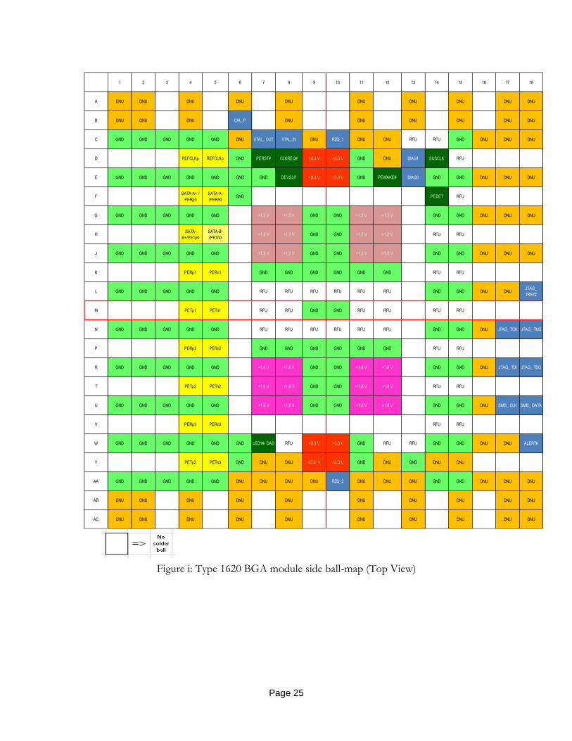
3.4.6 BGA SSD Soldered-Down Module Pin-out
All pinout tables in this section are written from the module point of view when referencing signal directions.
This section contains the module side pin-out map for Type 1620 BGA module.
Figure i shows module-side pin-out for Type 1620 BGA.
There are additional sizes of 2024, 2228 and 2828 defined for BGA SSD. Ball maps for these sizes encompass the Type1620 ball map with additional DNU balls for mechanical stability. Refer to section 2.3.6 for details on the location of these DNU balls for various BGA package sizes.
Optional signals are shown in blue. The optional signals are CAL_P, XTAL_OUT, XTAL_IN, RZQ_1, RZQ_2, DIAG0, DIAG1, JTAG_TRST, JTAG_TCK, JTAG_TMS, JTAG_TDI, JTAG_TDO, SMB_CLK, SMB_DATA, and ALERT#.
The optional signals will be handled as follows for the host and module.
Host: If not implemented, the landing pads shall not be electrically connected to the host. If implemented, the host routes the signals as described in this specification.
Module If not implemented, the balls shall not be electrically connected to the module. If implemented, the module routes the signals as described in this specification.
Page 25
Figure i: Type 1620 BGA module side ball-map (Top View)
1 2 3 4 5 6 7 8 9 10 11 12 13 14 15 16 17 18
A DNU DNU DNU DNU DNU DNU DNU DNU DNU DNU
B DNU DNU DNU CAL_P DNU DNU DNU DNU DNU DNU
C GND GND GND GND GND DNU XTAL_ OUT XTAL_IN DNU RZQ_1 DNU DNU RFU RFU GND DNU DNU DNU
D REFCLKp REFCLKn GND PERST# CLKREQ# +3.3 V +3.3 V GND DNU DIAG1 SUSCLK RFU
E GND GND GND GND GND GND GND DEVSLP +3.3 V +3.3 V GND PEWAKE# DIAG0 GND GND DNU DNU DNU
FSATA-A+ /
PERp0
SATA-A-
/PERn0GND PEDET RFU
G GND GND GND GND GND +1.2 V +1.2 V GND GND +1.2 V +1.2 V GND GND DNU DNU DNU
HSATA-
B+/PETp0
SATA-B-
/PETn0+1.2 V +1.2 V GND GND +1.2 V +1.2 V RFU RFU
J GND GND GND GND GND +1.2 V +1.2 V GND GND +1.2 V +1.2 V GND GND DNU DNU DNU
K PERp1 PERn1 GND GND GND GND GND GND RFU RFU
L GND GND GND GND GND RFU RFU RFU RFU RFU RFU GND GND DNU DNUJTAG_
TRST#
M PETp1 PETn1 RFU RFU GND GND RFU RFU RFU RFU
N GND GND GND GND GND RFU RFU RFU RFU RFU RFU GND GND DNU JTAG_ TCK JTAG_ TMS
P PERp2 PERn2 GND GND GND GND GND GND RFU RFU
R GND GND GND GND GND +1.8 V +1.8 V GND GND +1.8 V +1.8 V GND GND DNU JTAG_ TDI JTAG_ TDO
T PETp2 PETn2 +1.8 V +1.8 V GND GND +1.8 V +1.8 V RFU RFU
U GND GND GND GND GND +1.8 V +1.8 V GND GND +1.8 V +1.8 V GND GND DNU SMB_ CLK SMB_ DATA
V PERp3 PERn3 RFU RFU
W GND GND GND GND GND GND LED1#/ DAS RFU +3.3 V +3.3 V GND RFU RFU GND GND DNU DNU ALERT#
Y PETp3 PETn3 GND DNU DNU +3.3 V +3.3 V GND DNU GND DNU DNU
AA GND GND GND GND GND DNU DNU DNU DNU RZQ_2 DNU DNU DNU GND GND DNU DNU DNU
AB DNU DNU DNU DNU DNU DNU DNU DNU DNU DNU
AC DNU DNU DNU DNU DNU DNU DNU DNU DNU DNU

Page 26
Figure j: Type 1620 BGA module side ball map surrounded by Type 2024, Type 2228, Type 2828 module side ball-maps (Top View)
Type 2828 1 2 3 5 6 7 8 9 10 11 12 13 14 15 16 17 18 19 20 21 22 23 24 25 26 27 28 30 31 32
1 2 3 4 5 6 7 8 9 10 11 12 13 14 15 16 17 18 19 20 21 22 23 24
1 2 3 4 5 6 7 8 9 10 11 12 13 14 15 16 17 18
A DNU DNU DNU DNU
B A DNU DNU DNU DNU DNU DNU DNU DNU DNU DNU DNU DNU
C B A DNU DNU DNU DNU DNU DNU
D C B DNU DNU DNU DNU
E D C DNU DNU
F E D A DNU DNU DNU DNU DNU DNU DNU DNU DNU DNU DNU DNU DNU DNU
G F E B DNU DNU DNU CAL_P DNU DNU DNU DNU DNU DNU
H G F C DNU DNU GND GND GND GND GND DNU XTAL_OUT XTAL_IN DNU RZQ_1 DNU DNU RFU RFU GND DNU DNU DNU DNU DNU
J H G D REFCLKp REFCLKn GND PERST# CLKREQ# +3.3 V +3.3 V GND DNU DIAG1SUSCL
KRFU
K J H E DNU DNU GND GND GND GND GND GND GND DEVSLP +3.3 V +3.3 V GND PEWAKE# DIAG0 GND GND DNU DNU DNU DNU DNU
L K J FSATA-
A+/PERp0
SATA-A-
/PERn0GND PEDET RFU
M L K G DNU DNU GND GND GND GND GND +1.2 V +1.2 V GND GND +1.2 V +1.2 V GND GND DNU DNU DNU DNU DNU
N M L HSATA-
B+/PETp0
SATA-B-
/PETn0+1.2 V +1.2 V GND GND +1.2 V +1.2 V RFU RFU
P N M J DNU GND GND GND GND GND +1.2 V +1.2 V GND GND +1.2 V +1.2 V GND GND DNU DNU DNU DNU
R P N K PERp1 PERn1 GND GND GND GND GND GND RFU RFU
T R P L DNU GND GND GND GND GND RFU RFU RFU RFU RFU RFU GND GND DNU DNUJTAG_
TRST#DNU
U T R M PETp1 PETn1 RFU RFU GND GND RFU RFU RFU RFU
V U T N DNU GND GND GND GND GND RFU RFU RFU RFU RFU RFU GND GND DNUJTAG_T
CK
JTAG_
TMSDNU
W V U P PERp2 PERn2 GND GND GND GND GND GND RFU RFU
Y W V R DNU GND GND GND GND GND +1.8 V +1.8 V GND GND +1.8 V +1.8 V GND GND DNUJTAG_T
DI
JTAG_
TDODNU
AA Y W T PETp2 PETn2 +1.8 V +1.8 V GND GND +1.8 V +1.8 V RFU RFU
AB AA Y U DNU DNU GND GND GND GND GND +1.8 V +1.8 V GND GND +1.8 V +1.8 V GND GND DNUSMB_C
LK
SMB_
DATADNU DNU
AC AB AA V PERp3 PERn3 RFU RFU
AD AC AB W DNU DNU GND GND GND GND GND GNDLED1#/
DASRFU +3.3 V +3.3 V GND RFU RFU GND GND DNU DNU ALERT# DNU DNU
AE AD AC Y PETp3 PETn3 GND DNU DNU +3.3 V +3.3 V GND DNU GND DNU DNU
AF AE AD AA DNU DNU GND GND GND GND GND DNU DNU DNU DNU RZQ_2 DNU DNU DNU GND GND DNU DNU DNU DNU DNU
AG AF AE AB DNU DNU DNU DNU DNU DNU DNU DNU DNU DNU
AH AG AF AC DNU DNU DNU DNU DNU DNU DNU DNU DNU DNU DNU DNU DNU DNU
AJ AH AG DNU DNU
AK AJ AH DNU DNU DNU DNU
AL AK AJ DNU DNU DNU DNU DNU DNU
AM AL DNU DNU DNU DNU DNU DNU DNU DNU DNU DNU DNU DNU
AN DNU DNU DNU DNU
4 29
Type
2228Type 1620
Type
2024
Type 1620
Type 2024
Type 2228
Type 2828

Page 27
Update section 4.1 as follows:
Update section 4.2 to add more signals defined at 1.8V. Add section 4.3 to define electrical
requirements for the BGA package based SSDs.
4.2 1.8 V Logic Signal Requirements The 1.8 V card logic levels for single-ended digital signals (SDIO, UART, PCM/I2S, etc.) are given in Table 37. This table also defines the signaling levels for BGA SSD defined single-ended signals such as (PERST#, CLKREQ#, PEWAKE#, SUSCLK, SMB_CLK, SMB_DAT, ALERT#)
Table 37. DC Specification for 1.8 V Logic Signaling
Notes: (1) Applies to CLKREQ# pull-up on host system
Symbol Parameter Condition Min Max Unit Notes
VDD18 Supply Voltage 1.7 1.9 V
VIH Input High Voltage 0.7*VDD18 VDD18+0.3 V
VIL Input Low Voltage -0.3 0.3*VDD18 V
VOH Output High Voltage IOH = -1mA VDD18 Min
VDD18-0.45 V
VOL Output Low Voltage IOL = 1mA VDD18 Min
0.45 V
IIN Input Leakage Current 0 V to VDD18 -10 +10 μA
ILKG Output Leakage Current 0 V to VDD18 -50 +50 μA
CIN Input Pin Capacitance 10 pF
RPULL-UP Pull-up Resistance 9 60 kΩ 1

Page 28
4.3. Electrical requirements for BGA SSDs
4.3.1. Voltage Supply Power-On Sequencing
The host should apply the following recommendations for sequencing the voltages on the 3.3 V supply, the 1.8 V supply, and the 1.2 V supply during power-on:
After the voltage on the 1.8 V supply or the voltage on the 1.2 V supply reach 300 mV, the voltage on the 1.8 V supply should remain greater than the voltage on the 1.2 V supply by at least 200 mV.
The voltage on the 3.3 V supply has no timing relationship relative to the voltage on the 1.2 V supply or the voltage on the 1.8 V supply.
If the power-on sequencing recommendations are not followed, there is a risk that the device may not power-on correctly or the device may be damaged. These results are vendor specific, and the implications may not be seen immediately.
Figure k shows three valid power-on ramp examples.
Figure k: Power-On Sequencing
4.3.2. Voltage Supply Power-Off Sequencing
The host should apply the following recommendations for sequencing the voltages on the 3.3 V supply, the 1.8 V supply, and the 1.2 V supply during power-off:
Before the voltage on the 1.2 V supply and the voltage on the 1.8 V supply reach 300 mV, the voltage on the 1.8 V supply should remain greater than voltage on the 1.2 V supply by 200 mV.
After both the voltage on the 1.8 V supply and the voltage on the 1.2 V supply are below 300 mV, there is no specified relationship between them.
The voltage on the 3.3 V supply has no timing relationship relative to the voltage on the 1.2 V supply or the voltage on the 1.8 V supply.

Page 29
The voltage on all supplies should remain below 100 mV for at least 1 ms before the power-on sequence is restarted.
If the power-off sequencing recommendations are not followed, there is a risk that the device may not power-on correctly or the device may be damaged. These results are vendor specific, and the implications may not be seen immediately.
Figure l shows two valid power-off ramp examples.
Figure l: Power-Off sequence
4.3.3. Power Ramp Timing
The power ramp timing is defined as the time the power rail needs to ramp to a valid voltage shown in Table x. This timing is recommended for power-on only.
Table x: Power Ramp Timing
Supply Voltage Max*
3.3 V 35 ms
1.8 V 25 ms
1.2 V 20 ms
Note: *The minimum timing may be calculated from the maximum slew rate
recommendation in Table y.

Page 30
4.3.4. Power Rail Slew Rate
The maximum power rail slew rate is shown in Table y. These values are only defined for ESD protection purpose. They are not meant for inrush current control.
Table y: Power Rail Slew Rate
Symbol Parameter Max Condition
TSLEW_3.3 Voltage slew rate of the 3.3 V power rail
100 kV/s No Load
TSLEW_1.8 Voltage slew rate of the 1.8 V power rail
100 kV/s No Load
TSLEW_1.2 Voltage slew rate of the 1.2 V power rail
100 kV/s No Load
Update Table 38 as follows to add 1.8 V and 1.2 V
Table 38. Key Regulated Power Rail Parameters
Power Rail Voltage Tolerance Platform Rail Type
+3.3 V ± 5% Always On
+1.8 V ± 5.55% Always On
+1.2 V ± 5% Always On
Update section 5.4 as follows to add BGA Pin-Outs
5.4 Soldered-Down Pinout Definitions The Soldered-down pinout definitions are shown in the following figures:
Figure 92, Type 2226 LGA Pin-Out Using Socket 1-SD Based Pin-Out on Platform
Figure 93, Type 1216 LGA Pin-Out Using Socket 1-SD Based Pin-Out on Platform
Figure 94, Type 3026 LGA Pin-Out Using Socket 1-SD & 1-DP Based Pin-Out on Platform
Figure 95, Type 1620 BGA Pinout On Platform (Top View)
Figure 96, Type 1620, Type 2024, Type 2228, Type 2828 BGA Pinout On Platform (Top View)

Page 31
Figure 95. Type 1620 BGA Pinout On Platform (Top View)
1 2 3 4 5 6 7 8 9 10 11 12 13 14 15 16 17 18
A DNU DNU DNU DNU DNU DNU DNU DNU DNU DNU
B DNU DNU DNU CAL_P DNU DNU DNU DNU DNU DNU
C GND GND GND GND GND DNU XTAL_OUT XTAL_IN DNU RZQ_1 DNU DNU RFU RFU GND DNU DNU DNU
D REFCLKp REFCLKn GND PERST# CLKREQ# +3.3 V +3.3 V GND DNU DIAG1 SUSCLK RFU
E GND GND GND GND GND GND GND DEVSLP +3.3 V +3.3 V GND PEWAKE# DIAG0 GND GND DNU DNU DNU
FSATA-A+ /
PETp0
SATA-A-
/PETn0GND PEDET RFU
G GND GND GND GND GND +1.2 V +1.2 V GND GND +1.2 V +1.2 V GND GND DNU DNU DNU
HSATA-
B+/PERp0
SATA-B-
/PERn0+1.2 V +1.2 V GND GND +1.2 V +1.2 V RFU RFU
J GND GND GND GND GND +1.2 V +1.2 V GND GND +1.2 V +1.2 V GND GND DNU DNU DNU
K PETp1 PETn1 GND GND GND GND GND GND RFU RFU
L GND GND GND GND GND RFU RFU RFU RFU RFU RFU GND GND DNU DNUJTAG_
TRST#
M PERp1 PERn1 RFU RFU GND GND RFU RFU RFU RFU
N GND GND GND GND GND RFU RFU RFU RFU RFU RFU GND GND DNU JTAG_ TCK JTAG_ TMS
P PETp2 PETn2 GND GND GND GND GND GND RFU RFU
R GND GND GND GND GND +1.8 V +1.8 V GND GND +1.8 V +1.8 V GND GND DNU JTAG_ TDI JTAG_ TDO
T PERp2 PERn2 +1.8 V +1.8 V GND GND +1.8 V +1.8 V RFU RFU
U GND GND GND GND GND +1.8 V +1.8 V GND GND +1.8 V +1.8 V GND GND DNU SMB_ CLK SMB_ DATA
V PETp3 PETn3 RFU RFU
W GND GND GND GND GND GND LED1#/ DAS RFU +3.3 V +3.3 V GND RFU RFU GND GND DNU DNU ALERT#
Y PERp3 PERn3 GND DNU DNU +3.3 V +3.3 V GND DNU GND DNU DNU
AA GND GND GND GND GND DNU DNU DNU DNU RZQ_2 DNU DNU DNU GND GND DNU DNU DNU
AB DNU DNU DNU DNU DNU DNU DNU DNU DNU DNU
AC DNU DNU DNU DNU DNU DNU DNU DNU DNU DNU

Page 32
Figure 96. Type 1620, Type 2024, Type 2228, Type 2828 BGA Pinout On Platform (Top View)
Type 2828 1 2 3 5 6 7 8 9 10 11 12 13 14 15 16 17 18 19 20 21 22 23 24 25 26 27 28 30 31 32
1 2 3 4 5 6 7 8 9 10 11 12 13 14 15 16 17 18 19 20 21 22 23 24
1 2 3 4 5 6 7 8 9 10 11 12 13 14 15 16 17 18
A DNU DNU DNU DNU
B A DNU DNU DNU DNU DNU DNU DNU DNU DNU DNU DNU DNU
C B A DNU DNU DNU DNU DNU DNU
D C B DNU DNU DNU DNU
E D C DNU DNU
F E D A DNU DNU DNU DNU DNU DNU DNU DNU DNU DNU DNU DNU DNU DNU
G F E B DNU DNU DNU CAL_P DNU DNU DNU DNU DNU DNU
H G F C DNU DNU GND GND GND GND GND DNU XTAL_OUT XTAL_IN DNU RZQ_1 DNU DNU RFU RFU GND DNU DNU DNU DNU DNU
J H G D REFCLKp REFCLKn GND PERST# CLKREQ# +3.3 V +3.3 V GND DNU DIAG1 SUSCLK RFU
K J H E DNU DNU GND GND GND GND GND GND GND DEVSLP +3.3 V +3.3 V GND PEWAKE# DIAG0 GND GND DNU DNU DNU DNU DNU
L K J FSATA-A+
/PETp0
SATA-A-
/PETn0GND PEDET RFU
M L K G DNU DNU GND GND GND GND GND +1.2 V +1.2 V GND GND +1.2 V +1.2 V GND GND DNU DNU DNU DNU DNU
N M L HSATA-B+
/PERp0
SATA-B-
/PERn0+1.2 V +1.2 V GND GND +1.2 V +1.2 V RFU RFU
P N M J DNU GND GND GND GND GND +1.2 V +1.2 V GND GND +1.2 V +1.2 V GND GND DNU DNU DNU DNU
R P N K PETp1 PETn1 GND GND GND GND GND GND RFU RFU
T R P L DNU GND GND GND GND GND RFU RFU RFU RFU RFU RFU GND GND DNU DNUJTAG_
TRST#DNU
U T R M PERp1 PERn1 RFU RFU GND GND RFU RFU RFU RFU
V U T N DNU GND GND GND GND GND RFU RFU RFU RFU RFU RFU GND GND DNUJTAG_T
CK
JTAG_
TMSDNU
W V U P PETp2 PETn2 GND GND GND GND GND GND RFU RFU
Y W V R DNU GND GND GND GND GND +1.8 V +1.8 V GND GND +1.8 V +1.8 V GND GND DNUJTAG_T
DI
JTAG_
TDODNU
AA Y W T PERp2 PERn2 +1.8 V +1.8 V GND GND +1.8 V +1.8 V RFU RFU
AB AA Y U DNU DNU GND GND GND GND GND +1.8 V +1.8 V GND GND +1.8 V +1.8 V GND GND DNUSMB_C
LK
SMB_
DATADNU DNU
AC AB AA V PETp3 PETn3 RFU RFU
AD AC AB W DNU DNU GND GND GND GND GND GNDLED1#/
DASRFU +3.3 V +3.3 V GND RFU RFU GND GND DNU DNU ALERT# DNU DNU
AE AD AC Y PERp3 PERn3 GND DNU DNU +3.3 V +3.3 V GND DNU GND DNU DNU
AF AE AD AA DNU DNU GND GND GND GND GND DNU DNU DNU DNU RZQ_2 DNU DNU DNU GND GND DNU DNU DNU DNU DNU
AG AF AE AB DNU DNU DNU DNU DNU DNU DNU DNU DNU DNU
AH AG AF AC DNU DNU DNU DNU DNU DNU DNU DNU DNU DNU DNU DNU DNU DNU
AJ AH AG DNU DNU
AK AJ AH DNU DNU DNU DNU
AL AK AJ DNU DNU DNU DNU DNU DNU
AM AL DNU DNU DNU DNU DNU DNU DNU DNU DNU DNU DNU DNU
AN DNU DNU DNU DNU
4 29
Type
2228
Type
2024
Type 1620
Type 1620
Type 2024
Type 2228
Type 2828

Page 33
Update annex section as follows:
6. Annex
6.1. Glossary
A Amperage or Amp PCIe Peripheral Component Interconnect Express
DC Direct Current SATA Serial Advanced Technology Attachment or Serial ATA
DNU Do Not Use PCM Pulse Code Modulation
GND Ground RF Radio Frequency
GNSS Global Navigation Satellite System (GPS+GLONASS)
RFU Reserved for Future Use
HDR Hybrid Digital Radio RMS Root Mean Square
HSIC High Speed Inter-Chip RoHS Restriction of Hazardous Substances Directive
I/F Interface RSS Root Sum Square
I/O (O/I) Input/Output (Output/Input) RTC Real Time Clock
IR Current x Resistance = Voltage SDIO Secure Digital Input Output
I2C Inter-Integrated Circuit SIM Subscriber Identity Module
I2S Integrated Interchip Sound SSD Sold-State Drive
LED Light Emitting Diode SSIC Super Speed USB Inter-Chip
LGA Land Grid Array UIM User Identity Module
m milli Ohm USB Universal Serial Bus
mA milli Amp UART Universal Asynchronous Receive Transmit
mV milli Volt V Voltage
NFC Near Field Communications W Wattage or Watts
M.2 Formally called Next Generation Form Factor (NGFF)
WiGig 60 GHz multi-gigabit speed wireless communication
NB Notebook WLAN Wireless Local Area Network
NIC Network Interface Card WPAN Wireless Personal Area Network
N/C Not Connected WWAN Wireless Wide Area Network

Page 34
Update Table 49 in section 6.3 as follows:
Table 4. Signal Integrity Requirements and Test Procedures for M.2
Parameter Procedure Requirements
Differential Insertion Loss (DDIL)
EIA 364-101
The EIA standard shall be used with the following considerations:
The measured differential S parameter shall be referenced to 85 Ω differential impedance.
The test fixture shall meet the test fixture requirement defined in Section 6.3.1.
The test fixture effect shall be removed from the measured S parameters. See Note 1.
≥ -0.5 dB up to 2.5 GHz;
≥ -[0.8*(f-2.5)+0.5] dB for 2.5 GHz < f ≤ 5 GHz (for example, ≥ -2.5 dB at f = 5 GHz);
≥ -[3.0*(f-5)+2.5] dB for 5 GHz < f ≤ 12 GHz (for example, ≥ -10 dB at f = 7.5 GHz)
Differential Return Loss (DDRL)
EIA 364-108
The EIA standard shall be used with the following considerations:
The measured differential S parameter shall be referenced to 85 Ω differential impedance.
The test fixture shall meet the test fixture requirement defined in Section 6.3.1.
The test fixture effect shall be removed from the measured S parameters. See Note 1.
≤ -15 dB up to 3 GHz;
≤ 5*f - 30 dB for 3 GHz < f ≤ 5 GHz;
≤ -1 dB for 5 GHz < f ≤ 12 GHz
Intra-pair Skew
(Soldered-down BGA)
Intra-pair skew must be achieved by design; measurement not required.
1 ps max
Intra-pair Skew
(BGA mounted on the M.2 module)
Intra-pair skew must be achieved by design; measurement not required.
2 ps max
Differential Near End Crosstalk (DDNEXT) and Differential Far End Crosstalk (DDFEXT)
EIA 364-90
The EIA standard must be used with the following considerations:
The crosstalk requirement is with respect to all the adjacent differential pairs including the crosstalk from opposite sides of the connector.
This is a differential crosstalk requirement between a victim differential signal pair and all of its adjacent differential signal pairs. The measured differential S parameter shall be referenced to 85 Ω differential impedance.
≤ -32 dB up to 2.5 GHz;
≤ -26 dB for 2.5 GHz < f ≤ 5 GHz;
≤ -20 dB for 5 GHz < f ≤ 10 GHz
< -10 dB for 10 GHz < f ≤ 12 GHz