PCI Express Right Angle Connector System
16
www.erni.com PCI Express Right Angle Connector System Catalog E XXXXXX 09/08 Edition 1
Transcript of PCI Express Right Angle Connector System

www.erni.com
PCI Express Right Angle Connector System
Catalog E XXXXXX 09/08 Edition 1

Catalog E XXXXXX 09/08 Edition 1
www.erni.com
Catalog E XXXXXX 09/08 Edition 1 www.erni.com 1
PCI Express Right Angle Connector System
Table of Contents
General . . . . . . . . . . . . . . . . . . . . . . . . . . . . . . . . . . . . . . . . . . . . . . . . . . . . . . . . . . . . . . . . . . . . . . . . . . . . . . . . . . . . . . . . . . . . . . 2
Features . . . . . . . . . . . . . . . . . . . . . . . . . . . . . . . . . . . . . . . . . . . . . . . . . . . . . . . . . . . . . . . . . . . . . . . . . . . . . . . . . . . . . . . . . . . . . 2
Electrical and Mechanical Characteristics . . . . . . . . . . . . . . . . . . . . . . . . . . . . . . . . . . . . . . . . . . . . . . . . . . . . . . . . . . . . . . . . . . . . 3
X1 36 Pin. . . . . . . . . . . . . . . . . . . . . . . . . . . . . . . . . . . . . . . . . . . . . . . . . . . . . . . . . . . . . . . . . . . . . . . . . . . . . . . . . . . . . . . . . . 4, 5
X4 64 Pin. . . . . . . . . . . . . . . . . . . . . . . . . . . . . . . . . . . . . . . . . . . . . . . . . . . . . . . . . . . . . . . . . . . . . . . . . . . . . . . . . . . . . . . . . . 6, 7
X8 98 Pin. . . . . . . . . . . . . . . . . . . . . . . . . . . . . . . . . . . . . . . . . . . . . . . . . . . . . . . . . . . . . . . . . . . . . . . . . . . . . . . . . . . . . . . . . . 8, 9
X16 164 Pin. . . . . . . . . . . . . . . . . . . . . . . . . . . . . . . . . . . . . . . . . . . . . . . . . . . . . . . . . . . . . . . . . . . . . . . . . . . . . . . . . . . . . . 10, 11
Part Number Index . . . . . . . . . . . . . . . . . . . . . . . . . . . . . . . . . . . . . . . . . . . . . . . . . . . . . . . . . . . . . . . . . . . . . . . . . . . . . . . . . . . . 12

PCI Express Right Angle Connector System
2 Catalog E XXXXXX 09/08 Edition 1 www.erni.com
The PCI Express (PCIe) Architecture was introduced into the market place in 2004 as a result of OEMs, including Intel, working together to design a next generation Bus Architecture. The current PCI Bus protocol has evol-ved from a 32 Bit PCI to 64 Bit PCI, PCI-X, causing the industry’s demand for greater speeds to outstrip the capabilities of PCI. The development of the PCIe pro-tocol has allowed the industry to embrace a new bus architecture that will handle the demands for the next 10 years. Completely compatible with PCI, the PCIe will allow designers greater flexibility when designing new systems and upgrading existing systems.
The ERNI Right Angle PCIe connector‘s footprint is identical to the standard vertical mount configuration. The connec-tor pins are insert molded into the connector to allow for exact registration of the contacts on both the daughter card side and the board mount thru hole side. The con-nector itself is molded out of a high temperature plastic. This allows the connector to withstand the higher reflow and IR temperatures required for processing lead free components. The overall rugged construction of this connector is fabricated with the best materials available for the application requirements. The Right Angle de-sign of the connector will enable the engineer to con-sider more options while designing the product where height is at premium.
Angled PCIe connector allows the system designer • to solve space problems that cannot be solved with vertical PCIe connectorsConnector enables the add-on card to be mounted • parallel to the motherboard, saving space in the overall height of the computer box Available in X1, X4, X8 or X16 versions in stack • heights of 5.84mm, 11.18mm, and 16.69mmMeets all PCIe Local Bus Standards Rev. 2.0• Plastic cover protects connector from dust and debris• Insert molded with liquid crystal polymer to provide • stability in hybrid board applications involving SMCsCompatible with wave soldering process•
General Features

Catalog E XXXXXX 09/08 Edition 1 www.erni.com 3
PCI Express Right Angle Connector System
Electrical and Mechanical Characteristics
Standard Right Angle Edge Card Connector
Number of Pins X1=36
X4=64
X8=98
X16=164
Process-conditions
Dip soldering temperature max. IEC 68-2-20 10s at 260 °C
Reflow soldering temperature max. JEDEC
J-STD-020C
20-90s at 260 °C
Housing Materials
Plastic material LCP 30% glass-filled
UL flame rating UL 94 V-0
Contact Materials
Base material Cu alloy
Mating area Gold Flash over Ni
Termination area Gold Flash over Ni
Marking
Technical Data
Temperature range -40 to +105°C
Current rating 1.1 A continuous
Voltag rating max 300 V
Dielectric strength >500 VAC at 60 Hz
Conductor resistance <40 mΩ
Insulation resistance >1 x 10⁹Ω at 500 VDC
Capacitance at 1 kHz As advertised
Inductance at 10 kHz As advertised
Impedance As advertised
Crosstalk Next >30 dB at 2.0 GHz
Propagation delay As advertised
Insertion Loss(for connectors with Dim. B = 5.84 mm)
<1 dB at 1.0 GHz
<3 dB at 2.5 GHz
Return Loss(for connectors with Dim. B = 5.84 mm)
>12 dB at 1.25 GHz
>7 dB at 1.5 GHz
>4 dB at 2.0 GHz
Product-approvalUL In Preparation
CSA In Preparation

PCI Express Right Angle Connector System
4 Catalog E XXXXXX 09/08 Edition 1 www.erni.com
Dimensional Drawings
All dimensions in mm. All images in first angle projection
25,5
15,2
4
3,12
14,9
B
Offset von Führungssteg zu Referenzzapfen 0.15Offset from guiding bar to reference peg
PIN 1
6
14,75
10
7,65 11,66
1,78
XXXX_XX ERNI RC X
DatumDate code
25,5
A1
Board hole pattern (component mounting side)Lochbild für Leiterplatte (Bestückungsseite)
B12B18
A18A12
B1
B2
A2
±0,
08
2
4,48
2,35
3
6
(2x)
0,7
10
2
2,5
1
1,35
9,15
Mittellinie LeiterplatteCenterline of daughter card
4CA
15,24
X1 Link Width, 36 pin
Catalog E XXXXXX 09/08 Edition 1 www.erni.com 5
PCI Express Right Angle Connector System
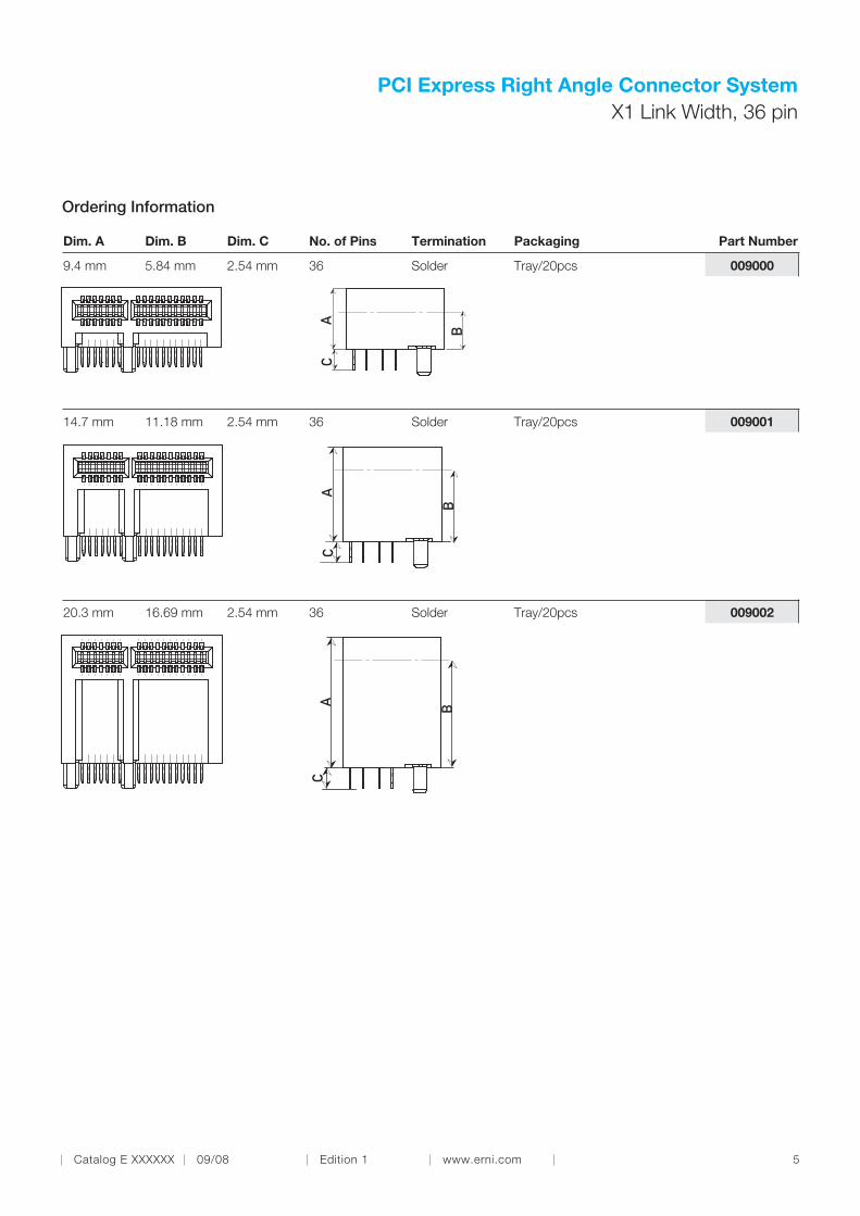
Dim. A Dim. B Dim. C No. of Pins Termination Packaging Part Number
X1 Link Width, 36 pin
AC
B
AC
B
AC
B
Ordering Information
0090009.4 mm 5.84 mm 2.54 mm 36 Solder Tray/20pcs
00900114.7 mm 11.18 mm 2.54 mm 36 Solder Tray/20pcs
00900220.3 mm 16.69 mm 2.54 mm 36 Solder Tray/20pcs

PCI Express Right Angle Connector System
6 Catalog E XXXXXX 09/08 Edition 1 www.erni.com
Dimensional Drawings
All dimensions in mm. All images in first angle projection
14,9
39,5
3,12
15,2
4
B
A12
Board hole pattern (component mounting side)Lochbild für Leiterplatte (Bestückungsseite)
B1
B2
A1
A2
B12
A32
B32
2,35
10
3
22
2,5
1
4,48
23,15
1,35 (2x)
0,7
±0,
08 20
XXXX_XX ERNI RC X
DatumDate code
39,5
Mittellinie LeiterplatteCenterline of daughter card
15,24
4CA
Offset from guiding bar to reference pegOffset von Führungssteg zu Referenzzapfen 0.15
PIN 1
11,6621,65
20 10
1,7814,75
X4 Link Width, 64 pin

Catalog E XXXXXX 09/08 Edition 1 www.erni.com 7
PCI Express Right Angle Connector System
X4 Link Width, 64 pin
Dim. A Dim. B Dim. C No. of Pins Termination Packaging Part Number
AC
B
AC
B
AC
B
Ordering Information
0090039.4 mm 5.84 mm 2.54 mm 64 Solder Tray/20pcs
00900414.7 mm 11.18 mm 2.54 mm 64 Solder Tray/20pcs
00900520.3 mm 16.69 mm 2.54 mm 64 Solder Tray/20pcs

PCI Express Right Angle Connector System
8 Catalog E XXXXXX 09/08 Edition 1 www.erni.com
Dimensional Drawings
All dimensions in mm. All images in first angle projection
B
56,5
14,9
3,12
15,2
4
Mittellinie LeiterplatteCenterline of daughter card
4CA
15,24
XXXX_XX ERNI RC X
DatumDate code
56,5
Board hole pattern ( component mounting side)Lochbild für Leiterplatte ( Bestückungsseite)
B12B49
A49
A12
B1B2
A1A2
2
2
±0,
08
2,5
40,15
1,35
2,35
3
37
(2x)
0,7
10
1
4,48
Offset von Führungssteg zu Referenzzapfen 0.15Offset from guiding bar to reference peg
PIN 1
37
11,6638,66
10
1,7814,75
X8 Link Width, 96 pin

Catalog E XXXXXX 09/08 Edition 1 www.erni.com 9
PCI Express Right Angle Connector System
AC
B
AC
B
AC
B
Dim. A Dim. B Dim. C No. of Pins Termination Packaging Part Number
Ordering Information
0090069.4 mm 5.84 mm 2.54 mm 96 Solder Tray/20pcs
00900714.7 mm 11.18 mm 2.54 mm 96 Solder Tray/20pcs
00900820.3 mm 16.69 mm 2.54 mm 96 Solder Tray/20pcs
X8 Link Width, 96 pin

PCI Express Right Angle Connector System
10 Catalog E XXXXXX 09/08 Edition 1 www.erni.com
89,5
14,9
3,12
15,2
4
B
Board hole pattern (component mounting side)Lochbild für Leiterplatte ( Bestückungsseite)
B2
B1
A1
A2
B12
A12A82
B82
73,15
2
±0,
08
2
2,5
2,35
370
(2x)
10
0,7
1,35
14,
48
Offset von Führungssteg zu Referenzzapfen 0.15Offset from guiding bar to reference peg
PIN 1
14,751,78
10
71,66 11,66
70
XXXX_XX ERNI RC X
DatumDate code
89,5
Mittellinie Leiterplattecenterline of daughter card
15,24
AC 4
Dimensional Drawings
All dimensions in mm. All images in first angle projection
X16 Link Width, 164 pin
Catalog E XXXXXX 09/08 Edition 1 www.erni.com 11
PCI Express Right Angle Connector System
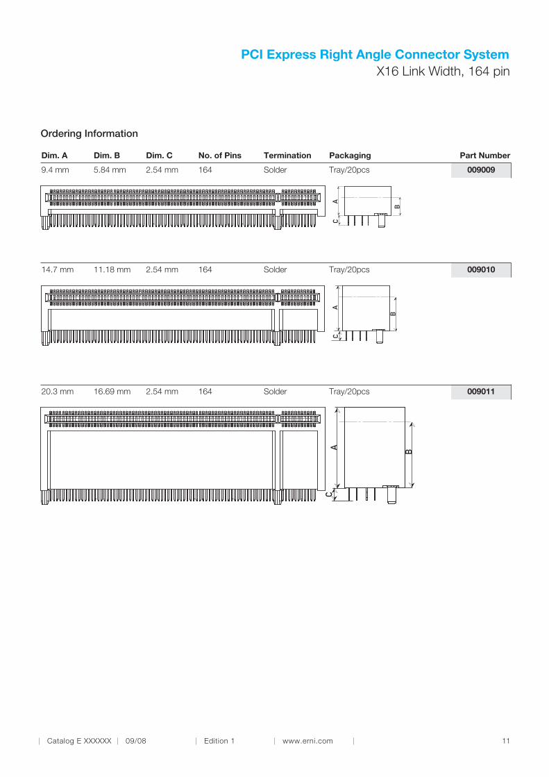
X16 Link Width, 164 pin
Dim. A Dim. B Dim. C No. of Pins Termination Packaging Part Number
AC
B
AC
B
AC
B
Ordering Information
0090099.4 mm 5.84 mm 2.54 mm 164 Solder Tray/20pcs
00901014.7 mm 11.18 mm 2.54 mm 164 Solder Tray/20pcs
00901120.3 mm 16.69 mm 2.54 mm 164 Solder Tray/20pcs

PCI Express Right Angle Connector System
12 Catalog E XXXXXX 09/08 Edition 1 www.erni.com
Part Number Index
009000 . . . . . . . . . . . . . . . . . . . . . . . . . . . . . . . . . . . . 4, 5
009001 . . . . . . . . . . . . . . . . . . . . . . . . . . . . . . . . . . . . 4, 5
009002 . . . . . . . . . . . . . . . . . . . . . . . . . . . . . . . . . . . . 4, 5
009003 . . . . . . . . . . . . . . . . . . . . . . . . . . . . . . . . . . . . 6, 7
009004 . . . . . . . . . . . . . . . . . . . . . . . . . . . . . . . . . . . . 6, 7
009005 . . . . . . . . . . . . . . . . . . . . . . . . . . . . . . . . . . . . 6, 7
009006 . . . . . . . . . . . . . . . . . . . . . . . . . . . . . . . . . . . . 8, 9
009007 . . . . . . . . . . . . . . . . . . . . . . . . . . . . . . . . . . . . 8, 9
009008 . . . . . . . . . . . . . . . . . . . . . . . . . . . . . . . . . . . . 8, 9
009009 . . . . . . . . . . . . . . . . . . . . . . . . . . . . . . . . . . 10, 11
009010 . . . . . . . . . . . . . . . . . . . . . . . . . . . . . . . . . . 10, 11
009011 . . . . . . . . . . . . . . . . . . . . . . . . . . . . . . . . . . 10, 11
Part Number Page

Catalog E XXXXXX 09/08 Edition 1
www.erni.com
Member

© ERNI Electronics GmbH 2008 • Printed in Germany. A policy of continuous improvement is followed and the right to alter any published data without notice is reserved. ERNI®,
MicroStac®, MicroSpeed
®, MiniBridge
®, MaxiBridge
®, ERmet
®, ERmet ZD
®, ERbic
® and ERNIPRESS
® are trademarks (registered or applied for in various countries) of ERNI Elec-
tronics GmbH.
ERNI Electronics GmbH Europe South America Africa Japan
Seestrasse 9
73099 Adelberg, Germany
Tel +49 7166 50-0
Fax +49 7166 50-282
ERNI Electronics, Inc. North America Canada Mexico
3005 E. Boundary Terrace
Midlothian, VA 23112
Tel +1 804 228-4100
Fax +1 804 228-4099
ERNI Asia Holding Pte Ltd. Asia
Blk 4008 Ang Mo Kio Avenue 10
#04-01/02 Techplace I
Singapore 569625
Tel +65 6 555 5885
Fax +65 6 555 5995
www.erni.com
Catalog E XXXXXX 09/08 Edition 1


![fileUSB 2. use 2 0 usg CIR 'Conector CIR CIR .ClR.pa3böV 'CIR:] PC Play pc WORLD . PCI xls PCI Express 2.0 2 C xlE 20116 20 x 16 O Connector use 2.0](https://static.fdocuments.in/doc/165x107/5cf67b4e88c993e14d8b60fc/2-use-2-0-usg-cir-conector-cir-cir-clrpa3boev-cir-pc-play-pc-world-pci.jpg)

![Programmable ECL IO with PCI DMAdyneng.com/pci_necl_xg1_man_a2.pdf · 2010. 12. 17. · The PCI-Serial-ECL has both ECL and TTL IO interfaced by a D100 connector. The TTL IO [11-0]](https://static.fdocuments.in/doc/165x107/60cdf6110356bf51da2c3b32/programmable-ecl-io-with-pci-2010-12-17-the-pci-serial-ecl-has-both-ecl-and.jpg)