PC Programming Manual - idehal.org · Pure IP-PBX PC Programming Manual Thank you for purchasing a...
1018
Pure IP-PBX PC Programming Manual Thank you for purchasing a Panasonic Pure IP-PBX. Please read this manual carefully before using this product and save this manual for future use. KX-TDE100/KX-TDE200: PMMPR Software File Version 3.0000 or later KX-TDE600: PGMPR Software File Version 3.0000 or later Model No. KX-TDE100 KX-TDE200/KX-TDE600
Transcript of PC Programming Manual - idehal.org · Pure IP-PBX PC Programming Manual Thank you for purchasing a...

Pure IP-PBX
PC Programming Manual
Thank you for purchasing a Panasonic Pure IP-PBX.
Please read this manual carefully before using this product and save this manual for future use.
KX-TDE100/KX-TDE200: PMMPR Software File Version 3.0000 or later
KX-TDE600: PGMPR Software File Version 3.0000 or later
Model No. KX-TDE100 KX-TDE200/KX-TDE600

IntroductionAbout this Programming Manual
The PC Programming Manual is designed to serve as a system programming reference for the PanasonicPure IP-PBX. It explains how to programme this PBX using the Maintenance Console software.The PC Programming Manual is divided into the following sections:
Section 1, OverviewProvides an overview of programming the PBX.
Section 2, Introduction of Maintenance ConsoleExplains the layout and menus of the Maintenance Console.
Section 3 – 13, Maintenance Console Operating InstructionsServes as reference operating instructions when using the Maintenance Console software to programme thePBX.
Section 14, AppendixProvides a list of changes from the previous version of each model.
Feature Programming ReferencesProvides a list of all related PC programming items for each feature.
References Found in the PC Programming ManualProgramming Manual ReferencesRelated sections of the PC Programming Manual are listed for your reference.
Feature Guide ReferencesThe Feature Guide explains what the PBX can do, as well as how to obtain the most of its many features andfacilities. Sections from the Feature Guide are listed throughout this manual for your reference.
Installation Manual ReferencesThe Installation Manual provides instructions detailing the installation and maintenance of the PBX.Sections from the Installation Manual are listed throughout this manual for your reference.
Links to Other Pages and ManualsIf you are viewing this manual with a PC, certain items are linked to different sections of this and other PBXmanuals. Click on a link to jump to that section.Linked items include:• Installation Manual References• PC Programming Manual References• Feature Guide References
Safety NoticesPlease observe the safety notices in this manual in order to avoid danger to users or other people, and preventdamage to property.The notices are classified as follows, according to the severity of injury or damage:
2 PC Programming Manual
Introduction
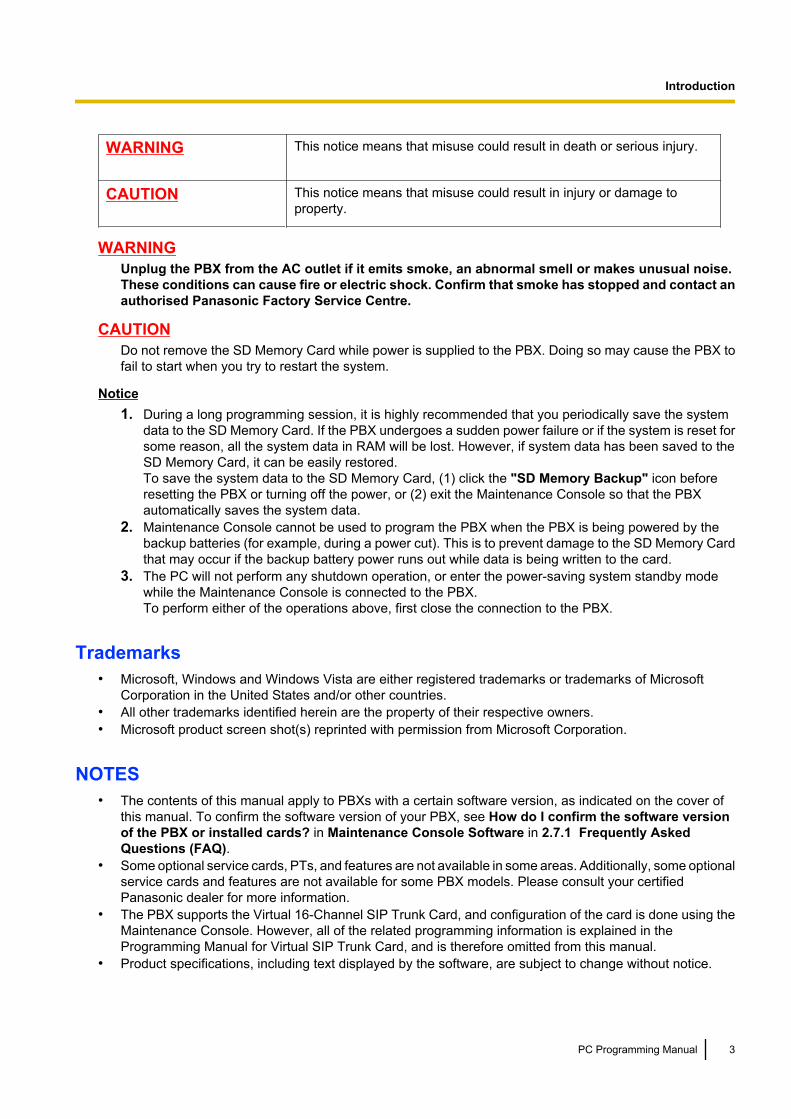
WARNING This notice means that misuse could result in death or serious injury.
CAUTION This notice means that misuse could result in injury or damage toproperty.
WARNINGUnplug the PBX from the AC outlet if it emits smoke, an abnormal smell or makes unusual noise.These conditions can cause fire or electric shock. Confirm that smoke has stopped and contact anauthorised Panasonic Factory Service Centre.
CAUTIONDo not remove the SD Memory Card while power is supplied to the PBX. Doing so may cause the PBX tofail to start when you try to restart the system.
Notice1. During a long programming session, it is highly recommended that you periodically save the system
data to the SD Memory Card. If the PBX undergoes a sudden power failure or if the system is reset forsome reason, all the system data in RAM will be lost. However, if system data has been saved to theSD Memory Card, it can be easily restored.To save the system data to the SD Memory Card, (1) click the "SD Memory Backup" icon beforeresetting the PBX or turning off the power, or (2) exit the Maintenance Console so that the PBXautomatically saves the system data.
2. Maintenance Console cannot be used to program the PBX when the PBX is being powered by thebackup batteries (for example, during a power cut). This is to prevent damage to the SD Memory Cardthat may occur if the backup battery power runs out while data is being written to the card.
3. The PC will not perform any shutdown operation, or enter the power-saving system standby modewhile the Maintenance Console is connected to the PBX.To perform either of the operations above, first close the connection to the PBX.
Trademarks• Microsoft, Windows and Windows Vista are either registered trademarks or trademarks of Microsoft
Corporation in the United States and/or other countries.• All other trademarks identified herein are the property of their respective owners.• Microsoft product screen shot(s) reprinted with permission from Microsoft Corporation.
NOTES• The contents of this manual apply to PBXs with a certain software version, as indicated on the cover of
this manual. To confirm the software version of your PBX, see How do I confirm the software versionof the PBX or installed cards? in Maintenance Console Software in 2.7.1 Frequently AskedQuestions (FAQ).
• Some optional service cards, PTs, and features are not available in some areas. Additionally, some optionalservice cards and features are not available for some PBX models. Please consult your certifiedPanasonic dealer for more information.
• The PBX supports the Virtual 16-Channel SIP Trunk Card, and configuration of the card is done using theMaintenance Console. However, all of the related programming information is explained in theProgramming Manual for Virtual SIP Trunk Card, and is therefore omitted from this manual.
• Product specifications, including text displayed by the software, are subject to change without notice.
PC Programming Manual 3
Introduction
In some cases, additional information, including updates to this and other manuals, is included in theMaintenance Console’s Information before programming. Install the latest version of MaintenanceConsole to view this information.
• In this manual, the suffix of each model number (e.g., KX-TDE100NE) is omitted unless necessary.
The KX-TDE100UK/KX-TDE200UK, KX-TDE100NE/KX-TDE200NE, KX-TDE100GR/KX-TDE200GR, and KX-TDE100CE/KX-TDE200CE are designed to interwork with the:• Analogue Public Switched Telephone Network (PSTN) of European countries• Pan-European Integrated Services Digital Network (ISDN) using ISDN basic rate
access• Pan-European Integrated Services Digital Network (ISDN) using ISDN primary rate
access• ONP 2048 kbit/s digital structured leased lines (D2048S)
The KX-TDE600UK, KX-TDE600NE, and KX-TDE600GR are designed to interwork withthe:• Analogue Public Switched Telephone Network (PSTN) of European countries• Pan-European Integrated Services Digital Network (ISDN) using ISDN basic rate
access• Pan-European Integrated Services Digital Network (ISDN) using ISDN primary rate
access• ONP 2048 kbit/s digital structured leased lines (D2048S)
Panasonic Communications Co., Ltd./Panasonic Communications Company (U.K.) Ltd. declares thatthis equipment is in compliance with the essential requirements and other relevant provisions of Radio& Telecommunications Terminal Equipment (R&TTE) Directive 1999/5/EC.Declarations of Conformity for the relevant Panasonic products described in this manual are availablefor download by visiting:
http://www.doc.panasonic.de
Contact to Authorised Representative:Panasonic Testing CentrePanasonic Marketing Europe GmbHWinsbergring 15, 22525 Hamburg, Germany
4 PC Programming Manual
Introduction

Table of Contents1 Overview .................................................................................................111.1 Introduction .....................................................................................................................121.1.1 Introduction .....................................................................................................................121.1.2 Entering Characters .......................................................................................................131.2 PC Programming .............................................................................................................171.2.1 Installing and Starting the Maintenance Console ...........................................................171.2.2 Password Security ..........................................................................................................22
2 Introduction of Maintenance Console ..................................................232.1 Introduction .....................................................................................................................242.1.1 Starting Maintenance Console and Software Modes .....................................................242.1.2 Access Levels ................................................................................................................272.1.3 Software Interface ..........................................................................................................312.1.4 Card Status ....................................................................................................................342.1.5 Display Options ..............................................................................................................352.1.6 Extension Number Setting ..............................................................................................362.2 Programme launcher ......................................................................................................372.2.1 Programme launcher—New ...........................................................................................372.2.2 Programme launcher—Open .........................................................................................382.2.3 Programme launcher—Connect—RS-232C ..................................................................392.2.4 Programme launcher—Connect—USB ..........................................................................402.2.5 Programme launcher—Connect—LAN ..........................................................................412.2.6 Programme launcher—Connect—Modem .....................................................................422.2.7 Programme launcher—Connect—ISDN Remote ...........................................................432.2.8 Programme launcher—Connect—Profile Setup .............................................................442.3 File ....................................................................................................................................452.3.1 File—Close .....................................................................................................................452.3.2 File—Save ......................................................................................................................462.3.3 File—Save As .................................................................................................................472.3.4 File—Exit ........................................................................................................................482.4 Disconnect .......................................................................................................................492.4.1 Disconnect—Disconnect ................................................................................................492.5 Tool ...................................................................................................................................502.5.1 Tool—SD memory backup .............................................................................................502.5.2 Tool—BRI Automatic Configuration ...............................................................................512.5.3 Tool—NDSS Link Data Clear .........................................................................................522.5.4 Tool—DXDP All OUS .....................................................................................................532.5.5 Tool—Simplified Voice Message—Delete All Recording ...............................................542.5.6 Tool—Simplified Voice Message—Check Current Usage .............................................552.5.7 Tool—Call Pickup for My Group .....................................................................................562.5.8 Tool—Extension List View ..............................................................................................572.5.9 Tool—Import ...................................................................................................................582.5.10 Tool—Export ..................................................................................................................622.5.11 Tool—Screen Customize—User Level/Administrator Level ...........................................632.6 Utility ................................................................................................................................642.6.1 Utility—Diagnosis ...........................................................................................................642.6.2 Utility—File Transfer PC to PBX (SD Card) ...................................................................672.6.3 Utility—File Transfer PBX (SD Card) to PC ...................................................................722.6.4 Utility—SD Card File View and Load ..............................................................................732.6.5 Utility—SD Card File Delete ...........................................................................................742.6.6 Utility—Message File Transfer PC to PBX .....................................................................752.6.7 Utility—Message File Transfer PBX to PC .....................................................................76
PC Programming Manual 5
Table of Contents

2.6.8 Utility—Error Log ............................................................................................................772.6.9 Utility—T1/E1 Signalling Bit Monitor ...............................................................................792.6.10 Utility—T1/E1 Line Trace ...............................................................................................802.6.11 Utility—ISDN/QSIG Protocol Trace ................................................................................812.6.12 Utility—V-IPGW16 Protocol Trace .................................................................................822.6.13 Utility—Digital Trunk Error Report ..................................................................................832.6.14 Utility—IP Extension Statistical Information ...................................................................842.6.15 Utility—CS Information ...................................................................................................852.6.16 Utility—PS Information ...................................................................................................862.6.17 Utility—CS Status Monitor ..............................................................................................872.6.18 Utility—Ping ....................................................................................................................882.6.19 Utility—File Transfer FTP to IP Equipment—IP-CS/NT400 ...........................................892.6.20 Utility—Card Software Timed Update ............................................................................902.6.21 Utility—System Reset—Reset by the Command ...........................................................912.7 Help ..................................................................................................................................932.7.1 Frequently Asked Questions (FAQ) ...............................................................................93
3 [1] Configuration ..................................................................................1033.1 [1-1] Slot .........................................................................................................................1043.2 [1-1] Slot—Summary .....................................................................................................1093.3 [1-1] Slot—Activation Key ............................................................................................1143.4 [1-1] Slot—Card Property - IPCMPR ............................................................................1173.5 [1-1] Slot—OPB3 Card Property ..................................................................................1373.6 [1-1] Slot—OPB3 Card Property—Card Command ....................................................1413.7 [1-1] Slot—Port Property - Virtual IP Gateway Port ...................................................1423.8 [1-1] Slot—Port Property - Virtual IP Gateway Port—Connection Command .........1443.9 [1-1] Slot—Shelf Property - Virtual IP Gateway ..........................................................1453.10 [1-1] Slot—Shelf Property - Virtual IP Gateway—GK Settings ..................................1693.11 [1-1] Slot—Shelf Property - Virtual IP Gateway—GW Settings .................................1703.12 [1-1] Slot—Shelf Property - Virtual IP Gateway—DN2IP ............................................1773.13 [1-1] Slot—Shelf Property - Virtual IP Gateway—Hunt Pattern .................................1793.14 [1-1] Slot—Card Property - Virtual IP Extension ........................................................1803.15 [1-1] Slot—Port Property - Virtual IP Extension .........................................................1873.16 [1-1] Slot—Port Property - Virtual IP Extension—Connection Command ...............1963.17 [1-1] Slot—Card Property - Virtual SIP Extension ......................................................1973.18 [1-1] Slot—Port Property - Virtual SIP Extension Port ...............................................2013.19 [1-1] Slot—Port Property - Virtual SIP Extension Port—Connection
Command .......................................................................................................................2063.20 [1-1] Slot—Card Property - Virtual IPCS .....................................................................2073.21 [1-1] Slot—Port Property - Virtual IPCS ......................................................................2143.22 [1-1] Slot—Port Property - Virtual IPCS—Connection Command ............................2233.23 [1-1] Slot—Card Property - Extension Type ...............................................................2243.24 [1-1] Slot—Port Property - Extension Port ..................................................................2303.25 [1-1] Slot—Port Property - Extension Port—Connection Command ........................2393.26 [1-1] Slot—Port Property - Extension Port—Port Type View ....................................2403.27 [1-1] Slot—Port Property - CSI/F Port ..........................................................................2413.28 [1-1] Slot—Port Property - CSI/F Port—Connection Command ................................2443.29 [1-1] Slot—Card Property - LCO type ..........................................................................2453.30 [1-1] Slot—Port Property - LCO Port ...........................................................................2583.31 [1-1] Slot—Port Property - LCO Port—Connection Command .................................2643.32 [1-1] Slot—Card Property - BRI type/PRI type ............................................................2653.33 [1-1] Slot—Port Property - BRI Port .............................................................................2803.34 [1-1] Slot—Port Property - BRI Port—Connection Command ...................................3053.35 [1-1] Slot—Port Property - PRI Port .............................................................................3063.36 [1-1] Slot—Port Property - PRI Port—Connection Command ...................................328
6 PC Programming Manual
Table of Contents

3.37 [1-1] Slot—Card Property - T1 type .............................................................................3293.38 [1-1] Slot—Port Property - T1 Port ...............................................................................3403.39 [1-1] Slot—Port Property - T1 Port—Connection Command .....................................3493.40 [1-1] Slot—Card Property - E1 type .............................................................................3503.41 [1-1] Slot—Card Property - E1 type—Line Signal Setting .........................................3593.42 [1-1] Slot—Card Property - E1 type—MFC-R2 Setting 1 ............................................3673.43 [1-1] Slot—Card Property - E1 type—MFC-R2 Setting 2 ............................................3733.44 [1-1] Slot—Port Property - E1 Port ..............................................................................3813.45 [1-1] Slot—Port Property - E1 Port—Connection Command ....................................3913.46 [1-1] Slot—Card Property - EM type ............................................................................3923.47 [1-1] Slot—Port Property - EM Port .............................................................................4013.48 [1-1] Slot—Port Property - EM Port—Connection Command ...................................4093.49 [1-1] Slot—Card Property - DID type ...........................................................................4103.50 [1-1] Slot—Port Property - DID Port .............................................................................4153.51 [1-1] Slot—Port Property - DID Port—Connection Command ...................................4223.52 [1-1] Slot—Card Property - IP Gateway .......................................................................4233.53 [1-1] Slot—Port Property - IP-GW Port ........................................................................4253.54 [1-1] Slot—Port Property - IP-GW Port—Connection Command ..............................4273.55 [1-1] Slot—Card Property - IP Extension ....................................................................4283.56 [1-1] Slot—Card Property - IP Extension—Common Settings ..................................4323.57 [1-1] Slot—Port Property - IP-Extension Port .............................................................4343.58 [1-1] Slot—OPB3 Card Property ..................................................................................4403.59 [1-1] Slot—OPB3 Card Property—Card Command ....................................................4463.60 [1-1] Slot—OPB3 Option Card Setup ...........................................................................4483.61 [1-2] Portable Station ....................................................................................................4503.62 [1-3] Option ....................................................................................................................4543.63 [1-4] Clock Priority ........................................................................................................456
4 [2] System .............................................................................................4574.1 [2-1-1] Date & Time—Date & Time Setting ..................................................................4584.2 [2-1-2] Date & Time—SNTP / Daylight Saving ............................................................4594.3 [2-1-2] Date & Time—SNTP / Daylight Saving—Daylight Saving ..............................4614.4 [2-2] Operator & BGM ...................................................................................................4634.5 [2-3] Timers & Counters ...............................................................................................4664.6 [2-4] Week Table ............................................................................................................4874.7 [2-4] Week Table—Time Setting ...................................................................................4884.8 [2-5] Holiday Table ........................................................................................................4914.9 [2-6-1] Numbering Plan—Main .....................................................................................4934.10 [2-6-2] Numbering Plan—Quick Dial ............................................................................5234.11 [2-6-3] Numbering Plan—B/NA DND Call Feature ......................................................5254.12 [2-7-1] Class of Service—COS Settings ......................................................................5294.13 [2-7-2] Class of Service—External Call Block ............................................................5444.14 [2-7-3] Class of Service—Internal Call Block ..............................................................5454.15 [2-8-1] Ring Tone Patterns—Call from CO ..................................................................5464.16 [2-8-2] Ring Tone Patterns—Call from Doorphone ....................................................5474.17 [2-8-3] Ring Tone Patterns—Call from Others ............................................................5484.18 [2-9] System Options ....................................................................................................5514.19 [2-10] Extension CID Settings ......................................................................................5794.20 [2-11-1] Audio Gain—Paging/MOH ..............................................................................5834.21 [2-11-2] Audio Gain—Card ...........................................................................................585
5 [3] Group ...............................................................................................5875.1 [3-1-1] Trunk Group—TRG Settings ............................................................................5885.2 [3-1-2] Trunk Group—Local Access Priority ..............................................................5965.3 [3-1-3] Caller ID Modification ........................................................................................597
PC Programming Manual 7
Table of Contents

5.4 [3-1-4] Dialling Plan .......................................................................................................6025.5 [3-1-4] Dialling Plan—Auto Assign ..............................................................................6045.6 [3-1-5] Trunk Group—Charge Rate ..............................................................................6055.7 [3-2] User Group ............................................................................................................6065.8 [3-3] Call Pickup Group ................................................................................................6075.9 [3-3] Call Pickup Group—All Setting ...........................................................................6095.10 [3-4] Paging Group ........................................................................................................6105.11 [3-4] Paging Group—All Setting ..................................................................................6125.12 [3-4] Paging Group—External Pager ...........................................................................6135.13 [3-5-1] Incoming Call Distribution Group—Group Settings ......................................6155.14 [3-5-1] Incoming Call Distribution Group—Group Settings—Member List .............6315.15 [3-5-2] Incoming Call Distribution Group—Queuing Time Table ..............................6335.16 [3-5-3] Incoming Call Distribution Group—Miscellaneous ........................................6345.17 [3-6] Extension Hunting Group ....................................................................................6365.18 [3-6] Extension Hunting Group—Member List ...........................................................6385.19 [3-7-1] VM(DPT) Group—System Settings ..................................................................6395.20 [3-7-2] VM(DPT) Group—Unit Settings ........................................................................6415.21 [3-7-2] VM(DPT) Group—Unit Settings—Member List ...............................................6425.22 [3-8-1] VM(DTMF) Group—System Settings ...............................................................6455.23 [3-8-2] VM(DTMF) Group—Group Settings .................................................................6545.24 [3-8-2] VM(DTMF) Group—Group Settings—Member List ........................................6565.25 [3-9] PS Ring Group ......................................................................................................6575.26 [3-9] PS Ring Group—Member List .............................................................................6595.27 [3-10] Conference Group ..............................................................................................6605.28 [3-10] Conference Group—Member List .....................................................................6615.29 [3-11] Air Synchronisation Group ................................................................................662
6 [4] Extension .........................................................................................6636.1 [4-1-1] Wired Extension—Extension Settings ............................................................6646.2 [4-1-1] Wired Extension—Extension Settings—CLIP Generate ................................7176.3 [4-1-2] Wired Extension—FWD/DND ............................................................................7206.4 [4-1-3] Wired Extension—Speed Dial ..........................................................................7226.5 [4-1-4] Wired Extension—Flexible Button ...................................................................7236.6 [4-1-4] Wired Extension—Flexible Button—Flexible button data copy ....................7416.7 [4-1-5] Wired Extension—PF Button ...........................................................................7426.8 [4-1-6] Wired Extension—NDSS Link Data - Send .....................................................7436.9 [4-1-7] Wired Extension—Simplified Voice Message .................................................7446.10 [4-2-1] Portable Station—Extension Settings .............................................................7476.11 [4-2-1] Portable Station—Extension Settings—CLIP Generate ................................7786.12 [4-2-2] Portable Station—FWD/DND ............................................................................7816.13 [4-2-3] Portable Station—Flexible Button ...................................................................7836.14 [4-2-3] Portable Station—Flexible Button—Flexible button data copy ....................7976.15 [4-2-4] Portable Station—NDSS Link Data - Send ......................................................7986.16 [4-2-5] Portable Station—Simplified Voice Message .................................................7996.17 [4-3] DSS Console .........................................................................................................8016.18 [4-3] DSS Console—DSS key data copy .....................................................................819
7 [5] Optional Device ...............................................................................8217.1 [5-1] Doorphone ............................................................................................................8227.2 [5-2] External Pager ......................................................................................................8267.3 [5-3-1] Voice Message—DISA System .........................................................................8277.4 [5-3-2] Voice Message—DISA Message ......................................................................8357.5 [5-3-3] Voice Message—SVM .......................................................................................8377.6 [5-4] External Relay .......................................................................................................8427.7 [5-5] External Sensor ....................................................................................................845
8 PC Programming Manual
Table of Contents
8 [6] Feature .............................................................................................8498.1 [6-1] System Speed Dial ...............................................................................................8508.2 [6-2] Hotel & Charge ......................................................................................................8528.3 [6-3] Verification Code ..................................................................................................8628.4 [6-4] Second Dial Tone .................................................................................................8658.5 [6-5] Absent Message ...................................................................................................8668.6 [6-6] Tenant ....................................................................................................................867
9 [7] TRS ...................................................................................................8699.1 [7-1] Denied Code ..........................................................................................................8709.2 [7-2] Exception Code ....................................................................................................8719.3 [7-3] Special Carrier ......................................................................................................8729.4 [7-4] Emergency Dial .....................................................................................................8739.5 [7-5] Miscellaneous .......................................................................................................874
10 [8] ARS ..................................................................................................87710.1 [8-1] System Setting ......................................................................................................87810.2 [8-2] Leading Number ...................................................................................................87910.3 [8-3] Routing Plan Time ................................................................................................88110.4 [8-3] Routing Plan Time—Time Setting .......................................................................88210.5 [8-4] Routing Plan Priority ............................................................................................88310.6 [8-5] Carrier ....................................................................................................................88410.7 [8-6] Leading Number Exception .................................................................................88710.8 [8-7] Authorisation Code for TRG ................................................................................888
11 [9] Private Network ...............................................................................88911.1 [9-1] TIE Table ................................................................................................................89011.2 [9-2] Network Data Transmission ................................................................................89411.3 [9-3] Network Operator (VoIP) ......................................................................................89811.4 [9-4] NDSS Key Table ....................................................................................................899
12 [10] CO & Incoming Call ......................................................................90112.1 [10-1] CO Line Settings .................................................................................................90212.2 [10-2] DIL Table & Port Settings ..................................................................................90512.3 [10-3] DDI / DID Table ....................................................................................................91612.4 [10-3] DDI/DID Table—Automatic Registration ...........................................................91912.5 [10-3] DDI/DID Table—Name Generate ........................................................................92112.6 [10-4] MSN Table ...........................................................................................................92312.7 [10-5] Miscellaneous .....................................................................................................928
13 [11] Maintenance ..................................................................................93113.1 [11-1] Main .....................................................................................................................93213.2 [11-2] PT Programming Access ...................................................................................95413.3 [11-3] Power Failure Transfer .......................................................................................95513.4 [11-4-1] SNMP—System Setting ..................................................................................95613.5 [11-4-2] SNMP—Manager ..............................................................................................95813.6 [11-5] Air Synchronisation ...........................................................................................961
14 Appendix ...............................................................................................96914.1 Revision History ............................................................................................................97014.1.1 KX-TDE100/KX-TDE200 PMMPR Software File Version 2.0xxx .................................97014.1.2 KX-TDE100/KX-TDE200 PMMPR Software File Version 2.01xx .................................97114.1.3 KX-TDE100/KX-TDE200 PMMPR Software File Version 3.0xxx .................................97214.1.4 KX-TDE600 PGMPR Software File Version 3.0xxx .....................................................974
PC Programming Manual 9
Table of Contents

Feature Programming References ...........................................................977
10 PC Programming Manual
Table of Contents

Section 1
Overview
This section provides an overview of programming thePBX.
PC Programming Manual 11
1.1 Introduction
1.1.1 IntroductionThese programming instructions are designed to serve as an overall system programming reference for thePBX. Each feature in the PBX has default settings that can be changed to customise the PBX to yourrequirements. These settings control the functions of the PBX, and changing them is referred to as "systemprogramming".Only one person can perform system programming at a time. Any other users trying to enter programmingmode will be denied access.
Ways to ProgrammeThere are two programming methods:• PC (Personal Computer) Programming
All features and settings of the PBX can be programmed through PC programming with MaintenanceConsole. Installing and starting the Maintenance Console is described in Section 1.2 PC Programming.Individual PC programming items are described in Section 2 Introduction of Maintenance Console.
• PT (Proprietary Telephone) ProgrammingA subset of the features and settings of the PBX can be programmed using a PT. PT programming isdescribed in the PT Programming Manual.
12 PC Programming Manual
1.1.1 Introduction

1.1.2 Entering CharactersThe characters on a white background below can be used when storing a name, message, password or othertext entry data using a PC. The available characters vary according to the model of PBX.
Table 1 (Standard)
PC Programming Manual 13
1.1.2 Entering Characters

Table 2 (For CE model)
14 PC Programming Manual
1.1.2 Entering Characters

Table 3 (For RU model)
PC Programming Manual 15
1.1.2 Entering Characters
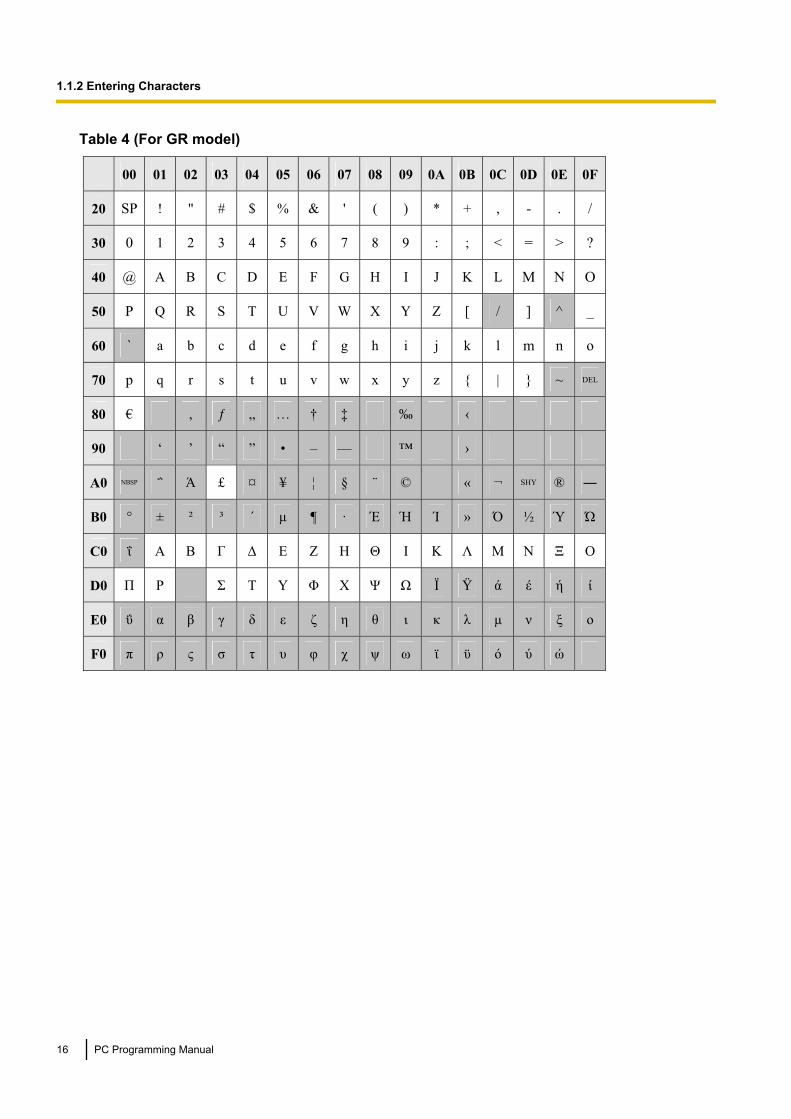
Table 4 (For GR model)
16 PC Programming Manual
1.1.2 Entering Characters

1.2 PC Programming
1.2.1 Installing and Starting the Maintenance ConsoleSystem programming, diagnosis and administration can be performed with a PC using the MaintenanceConsole.This section describes how to install and start the Maintenance Console.
System RequirementsRequired Operating System• Microsoft® Windows® XP or Windows Vista® Business operating systemMinimum Hardware Requirements• HDD: 100 MB of available hard disk spaceRecommended Display Settings• Screen resolution: XGA (1024 ´ 768)• DPI setting: Normal size (96 DPI)
PC Programming Manual 17
1.2.1 Installing and Starting the Maintenance Console

Installing the Maintenance ConsoleNote
• Make sure to install and use the latest version of the Maintenance Console.• To install or uninstall the software on a PC running Windows XP Professional, you must be logged in
as a user in either the "Administrators" or "Power Users" group.• To install or uninstall the software on a PC running Windows Vista Business, you must be logged in
as a user in the "Administrators" group.1. Copy the setup file of the Maintenance Console to your PC.2. Double-click the setup file to run the installer.3. Follow the on-screen instructions provided by the installation wizard.
Starting the Maintenance Console and Assigning the Basic Items (QuickSetup)
When you start the Maintenance Console with the Installer Level Programmer Code and connect to the PBXfor the first time after initialisation (with the factory default setting), Quick Setup will launch automatically. DuringQuick Setup, you will set up the following basic items. For details about the basic items, refer to "2.3.4 QuickSetup" in the Feature Guide.
1. Connect the PC to the PBX with an Ethernet straight cable or RS-232C cross cable.
2. Start the Maintenance Console from the Start menu.
3. "Information before programming" appears.
a. Carefully read this important additional information, which includes updates to this and othermanuals.
b. Click OK to close this window.
4. a. Enter the Installer Level Programmer Code (default: INSTALLER).
NoteThere are 2 other Programmer Codes with limited authorisation: Administrator Level (default:ADMIN), and User Level (default: USER). (® 1.2.2 Password Security)
b. Click OK.
5. Click Connect.
6. a. Select your PBX model from PBX Model.b. Select the LAN or RS-232C tab, depending on the type of PC connection with the PBX.c. Specify the settings as required. (See 2.1.1 Starting Maintenance Console and Software
Modes)
NoteWhen connecting to the PBX for the first time selecting LAN, the IP Address and PortNumber must be set to 192.168.0.101 and 35300 respectively.
d. Enter the system password for installer (default: 1234).e. Click Connect.
18 PC Programming Manual
1.2.1 Installing and Starting the Maintenance Console
7. When country/area data do not match:a. Click OK to replace the country/area data of the PBX. Replacement may take several minutes to
complete.b. Follow the procedure described in Section 3.16.1 Starting the PBX (for KX-TDE100/
KX-TDE200) or Section 3.15.1 Starting the PBX (for KX-TDE600) in the Installation Manual andrestart the PBX.
c. Repeat step 5 to reconnect the Maintenance Console to the PBX.
8. Follow the instructions of the Quick Setup wizard for the basic items in Quick Setup.
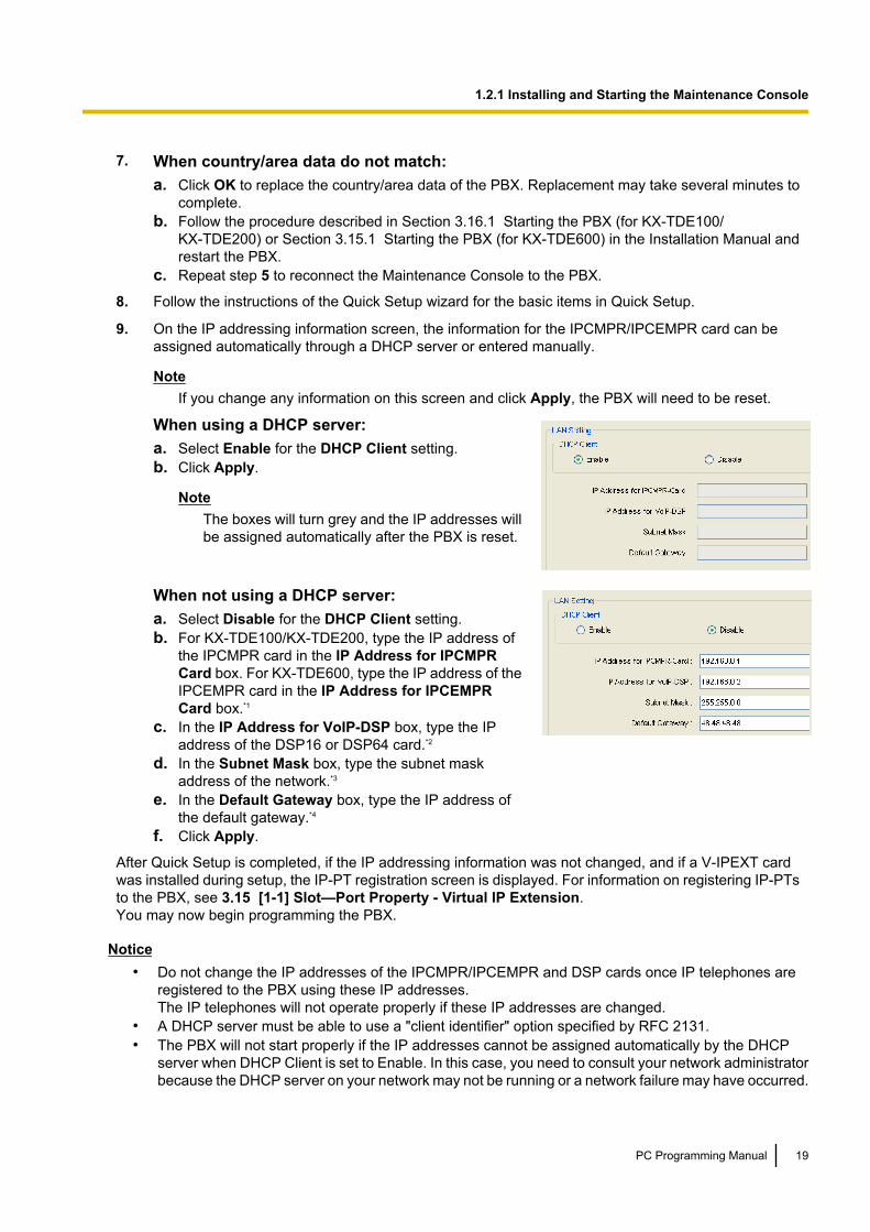
9. On the IP addressing information screen, the information for the IPCMPR/IPCEMPR card can beassigned automatically through a DHCP server or entered manually.
NoteIf you change any information on this screen and click Apply, the PBX will need to be reset.
When using a DHCP server:a. Select Enable for the DHCP Client setting.b. Click Apply.
NoteThe boxes will turn grey and the IP addresses willbe assigned automatically after the PBX is reset.
When not using a DHCP server:a. Select Disable for the DHCP Client setting.b. For KX-TDE100/KX-TDE200, type the IP address of
the IPCMPR card in the IP Address for IPCMPRCard box. For KX-TDE600, type the IP address of theIPCEMPR card in the IP Address for IPCEMPRCard box.*1
c. In the IP Address for VoIP-DSP box, type the IPaddress of the DSP16 or DSP64 card.*2
d. In the Subnet Mask box, type the subnet maskaddress of the network.*3
e. In the Default Gateway box, type the IP address ofthe default gateway.*4
f. Click Apply.
After Quick Setup is completed, if the IP addressing information was not changed, and if a V-IPEXT cardwas installed during setup, the IP-PT registration screen is displayed. For information on registering IP-PTsto the PBX, see 3.15 [1-1] Slot—Port Property - Virtual IP Extension.You may now begin programming the PBX.
Notice• Do not change the IP addresses of the IPCMPR/IPCEMPR and DSP cards once IP telephones are
registered to the PBX using these IP addresses.The IP telephones will not operate properly if these IP addresses are changed.
• A DHCP server must be able to use a "client identifier" option specified by RFC 2131.• The PBX will not start properly if the IP addresses cannot be assigned automatically by the DHCP
server when DHCP Client is set to Enable. In this case, you need to consult your network administratorbecause the DHCP server on your network may not be running or a network failure may have occurred.
PC Programming Manual 19
1.2.1 Installing and Starting the Maintenance Console

If the DHCP server is not available, change the DHCP Client setting to Disable and set fixed IPaddresses, then restart the PBX.To change the DHCP Client setting, connect the PC with an RS-232C cross cable or Ethernet straightcable. When connecting the PC with an Ethernet straight cable, make sure the PBX is disconnectedfrom the LAN and then connect the PC with an Ethernet straight cable using 192.168.0.101 for the IPaddress of the IPCMPR/IPCEMPR card.
*1 Valid IP address range: "1.0.0.0" to "223.255.255.255"*2 Valid IP address range: "1.0.0.0" to "223.255.255.255"*3 Valid subnet mask address range: "0–255.0–255.0–255.0–255" (except 0.0.0.0 and 255.255.255.255)*4 Valid IP address range: "0.0.0.0" to "223.255.255.255"
PBX Web ManagerIt is possible to use a PC with the Maintenance Console (PBX Unified PC Maintenance Console) installed, asa web server. This allows users to configure the PBX via a web browser on a local client, or a remote PCthrough the Internet.
PBXServer
Client
Remote PC
IP Network
If Maintenance Console is installed on the client PC, a web server is not necessary.
PBXServer/Client
Accessing PBX Web ManagerPBX Web Manager can be enabled during the installation of the Maintenance Console. It can also be enabledin Options.
Note• When starting the Maintenance Console, if there is less than 80 MB of available memory, this feature
is automatically disabled.• Only one user can access Maintenance Console or PBX Web Manager at any given time.
To start PBX Web Manager:
20 PC Programming Manual
1.2.1 Installing and Starting the Maintenance Console

1. If the PC is not the web server:Launch a web browsing application and enter thefollowing URL:"http://xxx:8181/INDEX.ASPX"’xxx’ should be replaced with the server’s IP address.
If the PC is the web server:Double-click the PBX Web Manager icon in the systemtray( ).
2. At the login screen input the PBX’s IP address, port, andpassword.Any profiles using LAN connection that have been savedwhen accessing the Maintenance Console directly willbe automatically displayed, for easy access to your PBX.
3. Click Connect.
PBX Web Manager Main MenuAfter successful login the main menu will appear where settings can be changed.
NoteWhile logged in, if there is no activity over a 5-minute period, PBX Web Manager will automaticallydisconnect.
PC Programming Manual 21
1.2.1 Installing and Starting the Maintenance Console

1.2.2 Password SecurityTo maintain system security, system passwords are required to access certain programming functions of thePBX. By giving different users access to different passwords, it is possible to control the amount ofprogramming that each user is able to perform.The following types of system passwords are available:
Password Description Format
System Password for User Used with the user-level programmer code to accessuser-level PC programming. The installer can specifywhich system programming settings are available.
4 – 10characters
System Password forAdministrator
Used with the administrator-level programmer code toaccess administrator-level PC programming. Theinstaller can specify which system programming settingsare available.
System Password forInstaller
Used with the installer-level programmer code to accessinstaller-level PC programming. All system programmingsettings are available.
The three programmer codes used for PC programming can be set through Maintenance Console. For moreinformation about programmer codes, see 2.1.2 Access Levels.
CAUTIONTo the Administrator or Installer regarding the system password1. Please provide all system passwords to the customer.2. To avoid unauthorised access and possible abuse of the PBX, keep the passwords secret, and inform
the customer of the importance of the passwords, and the possible dangers if they become known toothers.
3. The PBX has default passwords preset. For security, change these passwords the first time that youprogramme the PBX.
4. Change the passwords periodically.5. It is strongly recommended that passwords of 10 numbers or characters be used for maximum
protection against unauthorised access. For a list of numbers and characters that can be used in systempasswords, see 1.1.2 Entering Characters.
22 PC Programming Manual
1.2.2 Password Security

Section 2
Introduction of Maintenance Console
This section serves as reference operating instructionswhen using the Maintenance Console software toprogramme the PBX.
PC Programming Manual 23
2.1 Introduction
2.1.1 Starting Maintenance Console and Software ModesEvery time Maintenance Console is started, a dialogue box will appear. From here, you can enter any of the2 available software modes.• Batch mode
Batch mode allows you to create new system data files, and make modifications to system data files storedon your PC, without being connected to the PBX. When you connect to the PBX, the modified data will beuploaded at one time.
• Interactive modeInteractive mode allows you to directly modify the system data and settings stored in the PBX’s memoryfrom a PC that is connected to the PBX. This mode displays the system data that is currently being usedby the PBX, rather than the system data stored on the SD memory card. Data can be modified and resultsdisplayed in real time.
To start Maintenance Console in Batch mode1. Enter the relevant programmer code.2. Click OK.
The programme launcher will appear.3. Select an option.
• Select New to create a new system data file.• Select Open to open an existing system data file.
To start Maintenance Console in Interactive mode1. Enter the relevant programmer code.2. Click OK.
The programme launcher will appear.3. Click Connect.
Connection options will be displayed.• Select a Profile Name if you want to use a pre-saved profile. This option is only available when one
or more profiles have been previously stored.a. Select the profile to use from the drop-down list.b. If the system password for the PBX has not been stored with the profile, enter it.
If the system password has been stored with the selected profile, it does not need to be entered.• To enter the parameters manually, select the PBX Model and select the method of connecting to the
PBX.a. Specify the settings as required. For more details, see the tables below.b. Enter the system password for the PBX.
4. Click Connect.Maintenance Console will start, and automatically connect to the PBX. If this is the first time thatMaintenance Console has connected to the PBX, and the date and time of the PBX have not yet been set,the Quick Setup wizard will run. For more details, see Starting the Maintenance Console and Assigningthe Basic Items (Quick Setup).
24 PC Programming Manual
2.1.1 Starting Maintenance Console and Software Modes

Connection Settings for RS-232C
Setting Values Explanation
Port COMx Specify the number of the COM portassigned to the PC’s RS-232Cinterface. Only available COM portsare displayed.
Baud Rate (bps) 2400, 4800, 9600, 19200,38400, 57600, 115200
Specify the speed of datatransmission.
Connection Settings for Modem
Setting Values Explanation
Dial Number 1-9, 0, *, #, -, "," [comma], T, P,W
Enter the telephone number to bedialled to access the PBX.T: Converts the Dial Type from Pulseto Tone."," [comma], P, W: Inserts a pause.
Dial Type Auto(Tone), Auto(Pulse),Manual
Specify the outgoing dialling method.If Manual is chosen, dialling must bedone with a connected telephone.
Comment Max. 40 characters Enter a comment to identify the set ofvalues.
Port COMx Specify the number of the COM portassigned to the PC’s modeminterface.Only available COM ports will bedisplayed.
Baud Rate (bps) 1200, 2400, 4800, 9600,19200, 38400
Specify the speed of datatransmission.
Modem Initialise – Enter the modem initialise command,and click Initialise to send thecommand to the modem.For more details, refer to yourmodem’s instruction manual.
Connection Settings for LAN
Setting Values Explanation
IP Address 1.0.0.0–223.255.255.255 Specify the IP address of the PBX onthe LAN. Enter the same IP addressthat was input in IP Address forIPCMPR Card of 3.4 [1-1] Slot—Card Property - IPCMPR.It is also possible to search for the IPaddress by clicking Search.
PC Programming Manual 25
2.1.1 Starting Maintenance Console and Software Modes

Setting Values Explanation
Port Number 1–65535 Specify the port number used toaccess the PBX via LAN. Enter thesame port number that was input inMaintenance Port Number of3.4 [1-1] Slot—Card Property -IPCMPR.
Connection Setting for ISDN Remote
Setting Values Explanation
Dial Number 30 digits (consisting of 1-9, 0, *,#, -, and "," [comma])
Enter the telephone number to bedialled to access the PBX.
26 PC Programming Manual
2.1.1 Starting Maintenance Console and Software Modes

2.1.2 Access LevelsThere are three main levels of access to the Maintenance Console: User, Administrator and Installer. Eachlevel has its own Programmer Code, which must be entered to run the Maintenance Console. The allowedformat for each programmer code is as follows:
Item Length
User Level Programmer Code 0 – 16 characters
Administrator Level Programmer Code 4 – 16 characters
Installer Level Programmer Code 4 – 16 characters
Access to menu options within the Maintenance Console is restricted depending on the Programmer Code,and the current software mode (see 2.1.1 Starting Maintenance Console and Software Modes). When amenu option is limited to certain access levels, this is noted in this manual in the initial description of that menuoption, for example:"This option is only available at Installer level."If a sentence like this does not appear under the heading, the menu option is available at all levels.
The target users for each access level are as follows:
Access Level User
User For end users
Administrator For system administrators
Installer For dealers and system installers
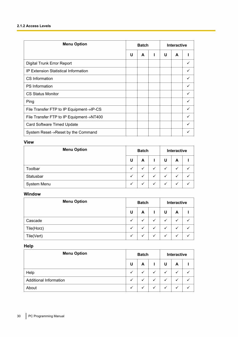
The options available in each mode and access level are shown below.The access levels are abbreviated as follows:U: User; A: Administrator; I: InstallerA check mark indicates that the menu option is available for that access level.
Programme launcherMenu Option Batch Interactive
U A I U A I
New ü ü
Open ü ü ü ü ü ü
Connect—RS-232C ü ü ü ü ü ü
Connect—USB ü ü ü ü ü ü
Connect—LAN ü ü ü ü ü ü
Connect—Modem ü ü ü ü ü ü
Connect—ISDN Remote ü ü ü ü ü ü
Connect—Profile Setup ü ü ü ü ü ü
PC Programming Manual 27
2.1.2 Access Levels

FileMenu Option Batch Interactive
U A I U A I
Close ü ü ü
Save ü ü ü
Save As ü ü ü
Exit ü ü ü ü ü ü
DisconnectMenu Option Batch Interactive
U A I U A I
Disconnect ü ü ü
ToolMenu Option Batch Interactive
U A I U A I
SD memory backup ü ü ü
BRI Automatic Configuration ü
NDSS Link Data Clear ü
DXDP All OUS ü
Simplified Voice Message®Delete All Recording ü
Simplified Voice Message®Check Current Usage ü
Call Pickup for My Group ü ü
Extension List View ü ü ü ü ü ü
Import®Feature - Speed Dial and Caller ID ü ü ü ü ü ü
Import®Incoming Call - DDI/DID Table ü ü
Import®ARS - Leading Digit ü ü
Import®ARS - Except Code ü ü
Import®ARS - Routing Plan ü ü
Import®Wired Extension ü ü
Import®PS Extension ü ü
Import®Quick Dial (Basic) ü ü
Import®Quick Dial (Expansion) ü ü
Import®SIP Extension ü ü
28 PC Programming Manual
2.1.2 Access Levels

Menu Option Batch Interactive
U A I U A I
Import®V-IPGW16 GW Settings ü ü
Import®V-IPGW16 DN2IP ü ü
Export®Feature - Speed Dial and Caller ID ü ü ü ü ü ü
Export®Incoming Call - DDI/DID Table ü ü
Export®ARS - Leading Digit ü ü
Export®ARS - Except Code ü ü
Export®ARS - Routing Plan ü ü
Export®Wired Extension ü ü
Export®PS Extension ü ü
Export®Quick Dial (Basic) ü ü
Export®Quick Dial (Expansion) ü ü
Export®SIP Extension ü ü
Export®V-IPGW16 GW Settings ü ü
Export®V-IPGW16 DN2IP ü ü
Screen Customize®User Level ü ü
Screen Customize®Administrator Level ü ü
UtilityMenu Option Batch Interactive
U A I U A I
Diagnosis ü ü ü
File Transfer PC to PBX (SD Card) ü
File Transfer PBX (SD Card) to PC ü
SD Card File View and Load ü
SD Card File Delete ü
Message File Transfer PC to PBX ü
Message File Transfer PBX to PC ü
Error Log ü ü ü
T1/E1 Signalling Bit Monitor ü
T1/E1 Line Trace ü
ISDN/QSIG Protocol Trace ü
V-IPGW16 Protocol Trace ü
PC Programming Manual 29
2.1.2 Access Levels
Menu Option Batch Interactive
U A I U A I
Digital Trunk Error Report ü
IP Extension Statistical Information ü
CS Information ü
PS Information ü
CS Status Monitor ü
Ping ü
File Transfer FTP to IP Equipment®IP-CS ü
File Transfer FTP to IP Equipment®NT400 ü
Card Software Timed Update ü
System Reset®Reset by the Command ü
ViewMenu Option Batch Interactive
U A I U A I
Toolbar ü ü ü ü ü ü
Statusbar ü ü ü ü ü ü
System Menu ü ü ü ü ü ü
WindowMenu Option Batch Interactive
U A I U A I
Cascade ü ü ü ü ü ü
Tile(Horz) ü ü ü ü ü ü
Tile(Vert) ü ü ü ü ü ü
HelpMenu Option Batch Interactive
U A I U A I
Help ü ü ü ü ü ü
Additional Information ü ü ü ü ü ü
About ü ü ü ü ü ü
30 PC Programming Manual
2.1.2 Access Levels
2.1.3 Software InterfaceThis section explains the functions of the various elements of the software interface.
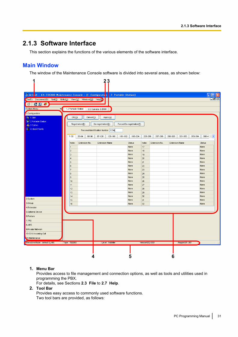
Main WindowThe window of the Maintenance Console software is divided into several areas, as shown below:
1 2 3
4 5 6
1. Menu BarProvides access to file management and connection options, as well as tools and utilities used inprogramming the PBX.For details, see Sections 2.3 File to 2.7 Help.
2. Tool BarProvides easy access to commonly used software functions.Two tool bars are provided, as follows:
PC Programming Manual 31
2.1.3 Software Interface
• FileContains the icon for saving files. For details, see Section 2.3.2 File—Save.
• ToolsContains icons for backing up PBX data to the SD Memory Card, viewing extension information, andaccessing Online Help. For details, see Sections 2.5.1 Tool—SD memory backup and 2.5.8 Tool—Extension List View.
These menus can be positioned freely. Click and drag the title bar of a menu to move it to another position.It will automatically snap in to position above, below, to the left, or to the right of the main window if releasedthere. Otherwise, it will float separately from the main window.Whether the tool bar is displayed or not can be chosen by selecting Toolbar from the View menu.
3. Tab BarThe name of each screen currently open is displayed in a tab in this tab bar. When multiple screens areopen at the same time, click on the tab of a screen to display the options associated with that screen.
4. System MenuProvides access to the settings used for programming the PBX, grouped into 11 topics.For details, see Sections Section 3 [1] Configuration to Section 13 [11] Maintenance.To display the individual screens within a topic, click the topic heading. It will expand to show the sub-topics.• If a sub-topic contains more than one screen, clicking the name of the sub-topic will display the names
of individual screens. Clicking an expanded sub-topic will hide the names of individual screens.Double-click on a screen name to open that screen in 6. Main Screen below.This menu can be positioned freely. Click and drag the title bar of the menu to move it to another position.It will automatically snap in to either the left side or right side of the main window if released there.Otherwise, it will float separately from the main window.Whether the system menu is displayed or not can be chosen by selecting System Menu from the Viewmenu.
5. Status BarThe status bar displays information on the current state of the Maintenance Console.Whether the status bar is displayed or not can be chosen by selecting Statusbar from the View menu.
The information displayed is as follows, in order from left to right:
Area Values Description
Programme Modeand ConnectionType
Programme Mode:Batch Mode xxxInteractive Mode yyy
Connection Type:RS-232CUSBLANModemISDN Remote
Displays the current programme mode andconnection type. See 2.1.1 StartingMaintenance Console and Software Modesabove."xxx" is replaced by the name of the currentsystem data file."yyy" is replaced by the name of the profile if used.
PBX Type Type: TDE100/TDE200/TDE600
Displays the type of PBX being programmed.
Access Level Level :UserAdministratorInstaller
Displays the current access level, determined bythe Programmer Code entered when startingMaintenance Console. See 2.1.2 AccessLevels for more information.
32 PC Programming Manual
2.1.3 Software Interface

Area Values Description
PBX System DataVersion
Versionxxx-xxx Displays the version number of the systemsoftware installed to the PBX.The first 3 digits are the version number, and thelast 3 digits are the revision number.
PBX Region Code Regionxxx-xxx Displays the region code assigned to the PBX andMaintenance Console.The first 3 digits represent the region codeassigned to the PBX, and the last 3 digitsrepresent the region code assigned to theMaintenance Console.
6. Main ScreenDisplays the screens selected from 4. System Menu above.For details, see Sections Section 3 [1] Configuration to Section 13 [11] Maintenance.
Standard Buttons and ElementsThere are several standard buttons that are displayed on many screens within the Maintenance Console.
The standard buttons are as follows:
Button Function
OK Implements changes and closes the current screen.
Cancel Abandons changes and returns to the previous screen.
Close Keeps any changes implemented, and closes the current screen.
Apply Implements changes and remains on the same screen.
Refresh Implements changes, updates displayed data, and remains on thecurrent screen.
Help Displays the relevant help topic for the current screen.
In addition, many screens within the software display a small open folder icon ( ) beside lists of setting items.Clicking this icon will collapse part of the list, allowing other items to be displayed. The icon will change to aclosed folder ( ).Clicking the closed folder icon will expand the list again.
PC Programming Manual 33
2.1.3 Software Interface

2.1.4 Card StatusCertain tools, utilities and settings require that the target card be set to out-of-service (OUS) or in-service (INS)status before the operation is carried out. Where required, this is noted in the description of each item. Cardstatus changes can only be performed when the software is in Interactive mode (see 2.1.1 StartingMaintenance Console and Software Modes).• "In service" means that the card is installed correctly in the PBX, and is capable of being used normally.• "Out of service" means that the card is installed correctly in the PBX, but has been temporarily removed
from use. This allows settings to be modified or software to be upgraded.• "Fault" means that the card is not installed in the PBX correctly, or is not functioning correctly. For more
information, see the Installation Manual.For details about how to change the status of a card, see To change the status (INS/OUS) of a card(Interactive mode only) on screen 3.1 [1-1] Slot.
34 PC Programming Manual
2.1.4 Card Status
2.1.5 Display OptionsThe View and Window menus provide options to control the display of items within the Maintenance Console.• View
– Toolbar: Displays or hides the tool bar of commonly used buttons.– Statusbar: Displays or hides the bar at the bottom of the Maintenance Console window.– System Menu: Displays or hides the menu of PBX setting screens.
• Window– Cascade: When multiple data screens are open, displays all open screens overlapped, with the title
bars visible.– Tile(Horz): When multiple data screens are open, displays all open screens side by side.– Tile(Vert): When multiple data screens are open, displays all open screens vertically.
PC Programming Manual 35
2.1.5 Display Options
2.1.6 Extension Number SettingMany screens within the Maintenance Console software allow you to select extensions as part of programmingvarious features (for example, as members of a group). These screens use a standard window to makeselecting multiple extensions easy, accessed by clicking a button. This section explains how to use thisExtension Number Setting window.
To select multiple extension numbers, select the type of extension to display, highlight the extensions you wishto add, then click the Add button. When finished, click OK. Data for the selected extensions will be added tothe first free spaces on the original screen.
Extension TypeSelects the types of extension numbers to display in Extension Numbers & Names List. Multiple itemscan be selected. Items that are not available are shown with a grey checkbox.
Value RangeWired Extension, Portable Station, VM Group(DPT), VM Group(DTMF), ICD Group, PS Ring Group,OGM(DISA), External Pager, Analogue MODEM, ISDN Remote
Extension Numbers & Names ListDisplays all available extensions of the types selected in Extension Type, and names. Click entries to selectthem, and click the Add button when finished, to add the selected extensions. To deselect an entry, click itagain.
Value RangeMatching extensions
Available ColumnSpecifies which fields in the original form to add extension data to. For example, if both extension numbersand names can be entered in the original form, it is possible to specify that extension name data not betransferred, by deselecting that field here.To select or deselect a field, click its name.
Value RangeAvailable fields
Selected Extension ListDisplays the extensions that have been selected to be added to member data. To remove an extension fromthis list, click it to select it and click Delete.
Value RangeSelected extensions
36 PC Programming Manual
2.1.6 Extension Number Setting

2.2 Programme launcher
2.2.1 Programme launcher—NewCreates a new system data file, used to programme the PBX in Batch mode. All settings are in their initial ordefault state.This option is only available at Installer level.To upload the file created here to the SD memory card installed in the PBX, see 2.6.2 Utility—File TransferPC to PBX (SD Card).
NoteSince selecting this option creates a blank system data file, uploading this file to the PBX will overwrite allprevious settings. Use only when necessary.
To create a new system data file1. From the programme launcher, select New.2. Click the appropriate model number.3. Click OK.
PC Programming Manual 37
2.2.1 Programme launcher—New

2.2.2 Programme launcher—OpenOpens a system data file previously saved on the PC, and enters Batch mode.
When opening a file created with an older version of the Maintenance Console, you will be asked whether youwant to convert the data for use with the current version or not. Using the data without converting may resultin some data being loaded to an incorrect destination, and is not recommended.
If the file is not supported by the PBX (e.g. a system data file from an incompatible PBX), it will not be opened.The only files that can be opened are files that were created by the Maintenance Console for a supported PBX.To upload a file opened here to the SD memory card installed in the PBX, see 2.6.2 Utility—File TransferPC to PBX (SD Card).
To open a system data file1. From the programme launcher, select Open.
The Open dialogue box will be displayed.2. Navigate to the folder containing the system data file you want to open.3. Select the file.4. Click Open.
If the file was created with an older version of the Maintenance Console, you will be asked if you want toconvert the data.• Click Yes to convert the data for use with the current version of the Maintenance Console. Enter a
name for the new converted system file.• Click No to open the file as it is.
38 PC Programming Manual
2.2.2 Programme launcher—Open

2.2.3 Programme launcher—Connect—RS-232CConnects to the PBX in Interactive mode through the serial RS-232C interface of the PBX.This option allows direct entry of connection parameters, for cases where the PC is used to connect to one orjust a few PBXs, and an individual profile for each PBX is not necessary. If you connect to multiple PBXs andwould prefer to choose from among pre-saved profiles instead, see 2.2.8 Programme launcher—Connect—Profile Setup for more details about creating profiles.
To connect to the PBX by RS-232C1. From the programme launcher, select Connect.
The Login window will be displayed.2. Select a connection option.
• Select a Profile Name if you want to use a pre-saved profile. This option is only available when oneor more profiles have been previously stored.a. Select the profile to use from the drop-down list.b. If the system password for the PBX has not been stored with the profile, enter it.
If the system password has been stored with the selected profile, it does not need to be entered.• To enter the parameters manually, select the PBX Model and confirm that the RS-232C radio button
is selected.a. Specify the settings as required. For more details, see the table below.b. Enter the system password for the PBX.
3. Click Connect.
Connection Settings for RS-232C
Setting Values Explanation
Port COMx Specify the number of the COM portassigned to the PC’s RS-232C interface.Only available COM ports are displayed.
Baud Rate (bps) 2400, 4800, 9600, 19200,38400, 57600, 115200
Specify the speed of data transmission.
PC Programming Manual 39
2.2.3 Programme launcher—Connect—RS-232C

2.2.4 Programme launcher—Connect—USBConnects to the PBX in Interactive mode through a USB port (USB Module) attached to the KX-DT300 seriesor KX-T7600 series DPT.
To connect to the PBX by USB1. From the programme launcher, select Connect.
The Login window will be displayed.2. Select a connection option.
• Select a Profile Name if you want to use a pre-saved profile.a. Select the profile to use from the drop-down list.b. If the system password for the PBX has not been stored with the profile, enter it.
If the system password has been stored with the selected profile, it does not need to be entered.• To enter the parameters manually, select the PBX Model and confirm that the USB radio button is
selected.a. Enter the system password for the PBX.
3. Click Connect.
40 PC Programming Manual
2.2.4 Programme launcher—Connect—USB

2.2.5 Programme launcher—Connect—LANConnects to the PBX in Interactive mode through the Local Area Network interface of the PBX.This option allows direct entry of connection parameters, for cases where the PC is used to connect to one orjust a few PBXs, and an individual profile for each PBX is not necessary. If you connect to multiple PBXs andwould prefer to choose from among pre-saved profiles instead, see 2.2.8 Programme launcher—Connect—Profile Setup for more details about creating profiles.
To connect to the PBX by LAN1. From the programme launcher, select Connect.
The Login window will be displayed.2. Select a connection option.
• Select a Profile Name if you want to use a pre-saved profile.a. Select the profile to use from the drop-down list.b. If the system password for the PBX has not been stored with the profile, enter it.
If the system password has been stored with the selected profile, it does not need to be entered.• To enter the parameters manually, select the PBX Model and confirm that the LAN radio button is
selected.a. Specify the settings as required. For more details, see the table below.b. Enter the system password for the PBX.
3. Click Connect.
Connection Settings for LAN
Setting Values Explanation
IP Address 1.0.0.0–223.255.255.255
Specify the IP address of the PBX on theLAN. Enter the same IP address that wasinput in IP Address for IPCMPR Card of3.4 [1-1] Slot—Card Property - IPCMPR.It is also possible to search for the IPaddress by clicking Search.
Port Number 1–65535 Specify the port number used to access thePBX via LAN. Enter the same port numberthat was input in Maintenance PortNumber of 3.4 [1-1] Slot—Card Property- IPCMPR.
PC Programming Manual 41
2.2.5 Programme launcher—Connect—LAN
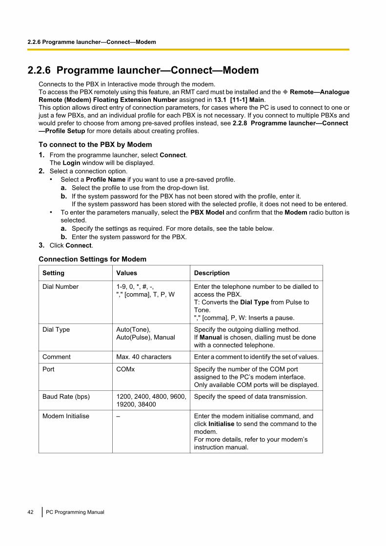
2.2.6 Programme launcher—Connect—ModemConnects to the PBX in Interactive mode through the modem.To access the PBX remotely using this feature, an RMT card must be installed and the Remote—AnalogueRemote (Modem) Floating Extension Number assigned in 13.1 [11-1] Main.This option allows direct entry of connection parameters, for cases where the PC is used to connect to one orjust a few PBXs, and an individual profile for each PBX is not necessary. If you connect to multiple PBXs andwould prefer to choose from among pre-saved profiles instead, see 2.2.8 Programme launcher—Connect—Profile Setup for more details about creating profiles.
To connect to the PBX by Modem1. From the programme launcher, select Connect.
The Login window will be displayed.2. Select a connection option.
• Select a Profile Name if you want to use a pre-saved profile.a. Select the profile to use from the drop-down list.b. If the system password for the PBX has not been stored with the profile, enter it.
If the system password has been stored with the selected profile, it does not need to be entered.• To enter the parameters manually, select the PBX Model and confirm that the Modem radio button is
selected.a. Specify the settings as required. For more details, see the table below.b. Enter the system password for the PBX.
3. Click Connect.
Connection Settings for Modem
Setting Values Description
Dial Number 1-9, 0, *, #, -,"," [comma], T, P, W
Enter the telephone number to be dialled toaccess the PBX.T: Converts the Dial Type from Pulse toTone."," [comma], P, W: Inserts a pause.
Dial Type Auto(Tone),Auto(Pulse), Manual
Specify the outgoing dialling method.If Manual is chosen, dialling must be donewith a connected telephone.
Comment Max. 40 characters Enter a comment to identify the set of values.
Port COMx Specify the number of the COM portassigned to the PC’s modem interface.Only available COM ports will be displayed.
Baud Rate (bps) 1200, 2400, 4800, 9600,19200, 38400
Specify the speed of data transmission.
Modem Initialise – Enter the modem initialise command, andclick Initialise to send the command to themodem.For more details, refer to your modem’sinstruction manual.
42 PC Programming Manual
2.2.6 Programme launcher—Connect—Modem
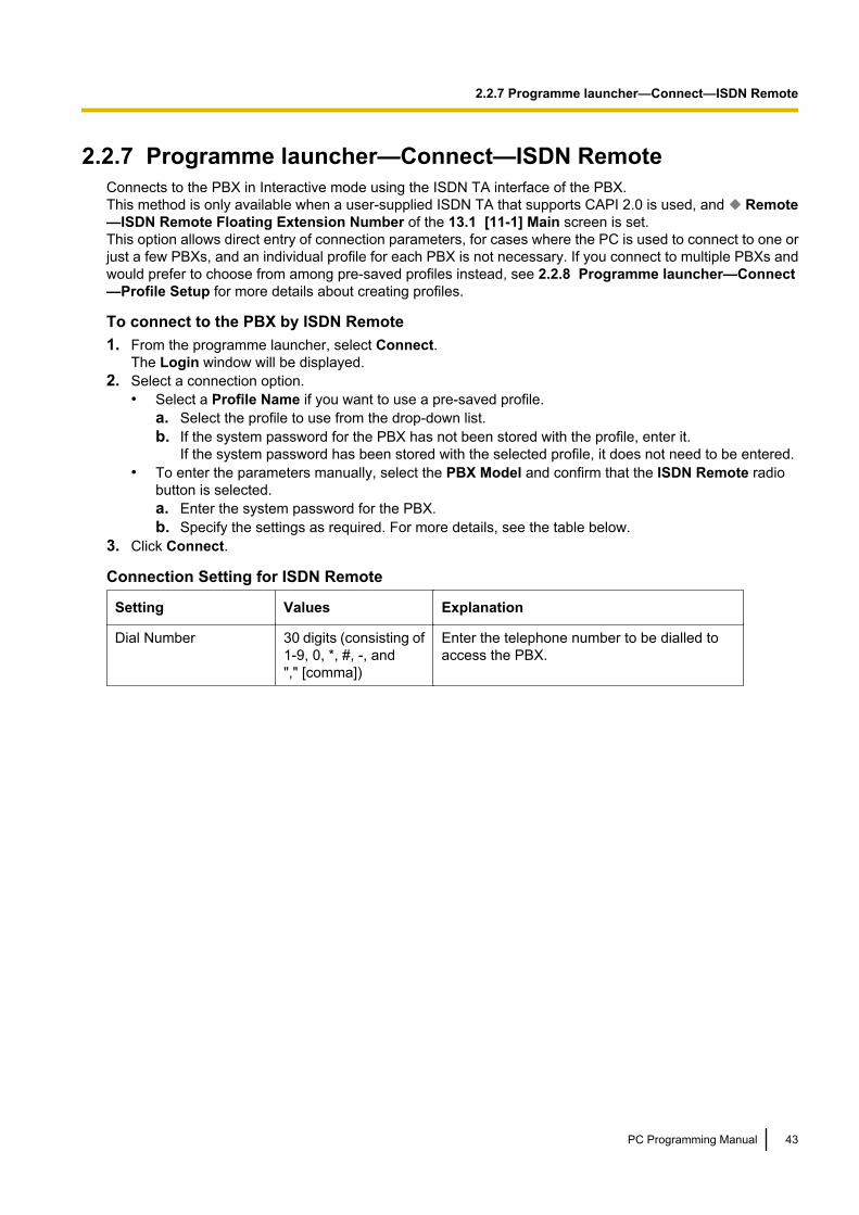
2.2.7 Programme launcher—Connect—ISDN RemoteConnects to the PBX in Interactive mode using the ISDN TA interface of the PBX.This method is only available when a user-supplied ISDN TA that supports CAPI 2.0 is used, and Remote—ISDN Remote Floating Extension Number of the 13.1 [11-1] Main screen is set.This option allows direct entry of connection parameters, for cases where the PC is used to connect to one orjust a few PBXs, and an individual profile for each PBX is not necessary. If you connect to multiple PBXs andwould prefer to choose from among pre-saved profiles instead, see 2.2.8 Programme launcher—Connect—Profile Setup for more details about creating profiles.
To connect to the PBX by ISDN Remote1. From the programme launcher, select Connect.
The Login window will be displayed.2. Select a connection option.
• Select a Profile Name if you want to use a pre-saved profile.a. Select the profile to use from the drop-down list.b. If the system password for the PBX has not been stored with the profile, enter it.
If the system password has been stored with the selected profile, it does not need to be entered.• To enter the parameters manually, select the PBX Model and confirm that the ISDN Remote radio
button is selected.a. Enter the system password for the PBX.b. Specify the settings as required. For more details, see the table below.
3. Click Connect.
Connection Setting for ISDN Remote
Setting Values Explanation
Dial Number 30 digits (consisting of1-9, 0, *, #, -, and"," [comma])
Enter the telephone number to be dialled toaccess the PBX.
PC Programming Manual 43
2.2.7 Programme launcher—Connect—ISDN Remote

2.2.8 Programme launcher—Connect—Profile SetupProfiles are useful when one PC is used to connect to multiple PBXs. Rather than manually adjusting theconnection settings each time a different PBX is accessed, it is possible to store the connection settings forseveral PBXs. Then, when you wish to connect to a specific PBX, you can simply choose that PBX’s profilefrom the list.
NoteWhen reinstalling or upgrading the Maintenance Console, it is possible to create a backup of all profiles.This allows you to use the original connection settings with the new Maintenance Console.
The functions of the buttons on this screen are as follows:
Button Function
Profile File Opens or saves profiles as separate files.
Save currentprofile
Overwrites the previous settings with the current settings when a profile already exists.A confirmation message will be displayed.
Save as newprofile
Saves the current settings as a new profile. A Profile Name is required.
Delete profile When an existing profile is selected, deletes that profile. A confirmation message willbe displayed.
44 PC Programming Manual
2.2.8 Programme launcher—Connect—Profile Setup

2.3 File
2.3.1 File—CloseCloses the system data file that is currently being modified, and returns to the programme launcher.
To close a system data file• From the File menu, select Close.
If the system data file has not been saved, a warning message will be displayed, giving you the option tosave the file.• Click Yes to save the file.• Click No to abandon the changes.
PC Programming Manual 45
2.3.1 File—Close

2.3.2 File—SaveOverwrites the previously saved system data file with the system data currently being modified in Batch mode.To upload a file saved here to the SD memory card installed in the PBX, see 2.6.2 Utility—File Transfer PCto PBX (SD Card).
To save a system data file• From the File menu, select Save.
If the data has never been saved, the Save dialogue box will be displayed. For more details, see 2.3.3 File—Save As.
46 PC Programming Manual
2.3.2 File—Save
2.3.3 File—Save AsSaves the system data file being modified in Batch mode with the name chosen by the user.To upload a file saved here to the SD memory card installed in the PBX, see 2.6.2 Utility—File Transfer PCto PBX (SD Card).
To save a system data file with a new name1. From the File menu, select Save As.2. Navigate to the folder in which you want to save the file.3. Enter a file name, or select a file to overwrite.4. Click Save.
If choosing to overwrite another file, a warning message will be displayed.• Click Yes to overwrite.• Click No to return to the previous screen.
PC Programming Manual 47
2.3.3 File—Save As
2.3.4 File—ExitCloses the Maintenance Console.
To exit the Maintenance Console• From the File menu, select Exit
If the system data file being modified has not been saved, a warning message will be displayed, giving youthe option to save the file.• Click Yes to save the file.• Click No to abandon the changes.
48 PC Programming Manual
2.3.4 File—Exit
2.4 Disconnect
2.4.1 Disconnect—DisconnectCloses the connection between the Maintenance Console and the PBX. When this option is chosen, systemdata is automatically backed up from the PBX to the SD memory card (see 2.5.1 Tool—SD memorybackup).
To disconnect1. From the Disconnect menu, select Disconnect.
A confirmation message will be displayed.2. Click Yes.
PC Programming Manual 49
2.4.1 Disconnect—Disconnect
2.5 Tool
2.5.1 Tool—SD memory backupSaves system data from the PBX to the SD memory card. Backup begins as soon as this option is chosen.
To back up system data• From the Tool menu, select SD memory backup.
50 PC Programming Manual
2.5.1 Tool—SD memory backup
2.5.2 Tool—BRI Automatic ConfigurationAutomatically configures the network settings of the BRI card.This option is only available at Installer level.This tool automatically inputs values into the fields L1 Mode, L2 Mode, Access Mode, and TEIMode, on the Network tab of the 3.33 [1-1] Slot—Port Property - BRI Port screen.
Note• Only one card can be configured at a time.• To use this tool, the card to be configured must be pre-set to OUS status. For more details, see
2.1.4 Card Status.When configuration is complete, the card is automatically returned to INS status.
• At any time on this screen, you can click Close to return to the previous screen without saving.
To configure the BRI card1. From the Tool menu, select BRI Automatic Configuration.2. Select the BRI card to configure by clicking the Check cell and setting it to ON.3. Click OK.
The ports associated with the selected BRI card will be displayed on a new screen.4. Enter suitable Subscriber Numbers for the ports you want to configure.
Only ports whose Subscriber Numbers have been entered will be configured.5. Click Execute.
The results of configuration will be displayed.6. Click the Check Box cell for the ports that have been configured.7. Click Data Apply to save these results to the BRI card.
PC Programming Manual 51
2.5.2 Tool—BRI Automatic Configuration

2.5.3 Tool—NDSS Link Data ClearClears NDSS Link Data stored in the connected PBX. While this tool clears both monitor extension andmonitored extension data, it only clears it at the connected PBX. To clear this data at other PBXs in the network,it is necessary to run this tool at those PBXs.
To clear the NDSS Link Data• From the Tool menu, select NDSS Link Data Clear.
A confirmation screen will be displayed.• Click OK to clear the data.• Click Cancel to keep the data, and close the screen.
52 PC Programming Manual
2.5.3 Tool—NDSS Link Data Clear

2.5.4 Tool—DXDP All OUSSets the status of all DXDP/XDP extension ports to "OUS" simultaneously.
To set all DXDP/XDP ports to OUS.1. From the Tool menu, select DXDP All OUS.2. Click OK.
PC Programming Manual 53
2.5.4 Tool—DXDP All OUS
2.5.5 Tool—Simplified Voice Message—Delete All RecordingDeletes all voice messages recorded by the SVM feature.
To delete voice messages1. From the Tool menu, point to Simplified Voice Message and select Delete All Recording.2. Select the card from which to delete messages.3. Click OK.
54 PC Programming Manual
2.5.5 Tool—Simplified Voice Message—Delete All Recording

2.5.6 Tool—Simplified Voice Message—Check Current UsageDisplays information on the voice messages stored by the SVM feature. For each message, the type ofmessage and the associated extension are displayed.
To view SVM message status• From the Tool menu, point to Simplified Voice Message and select Check Current Usage.
PC Programming Manual 55
2.5.6 Tool—Simplified Voice Message—Check Current Usage

2.5.7 Tool—Call Pickup for My GroupAllows you to automatically configure settings in 4.10 [2-6-2] Numbering Plan—Quick Dial and 6.4 [4-1-3]Wired Extension—Speed Dial so that users can answer calls to their Call Pickup Group by pressing " 0".
To activate this tool• From the Tool menu, select Call Pickup for My Group.
The Group Call Pickup feature number (default: 40) + the extension user group number of the extensionis assigned to first personal speed dial.
NoteThis tool can only be activated if all of the following conditions are met:– The first Quick Dial setting is empty or is already set to " 0".– " 0" is not used for another feature number.– The Group Call Pickup feature number has been assigned.– The Personal Speed Dialling feature number has been assigned.
56 PC Programming Manual
2.5.7 Tool—Call Pickup for My Group

2.5.8 Tool—Extension List ViewDisplays a list of all programmed extension numbers and types. It is possible to sort the information accordingto Extension Number, Type, Extension Name, Shelf, Slot, or Port. There is also a key-word searching feature.
The types that can be displayed are as follows:
Type Detail
Intercom Wired Extension
VM Voice Mail
Portable Station Wireless Extension (Portable Station)
ICDG Incoming Call Distribution Group
WG PS Ring Group
VM (DPT) VM (DPT) Group
VM (DTMF) VM (DTMF) Group
Pager External Pager
MODEM Analogue Modem
ISDN Remote ISDN Modem
OGM (DISA) DISA
DSS DSS Console
DPT-I/F CS PT-interface CS
SVM SVM Feature
SIP/IP-PT IP Telephone
To view extension information• From the Tool menu, select Extension List View.
PC Programming Manual 57
2.5.8 Tool—Extension List View

2.5.9 Tool—ImportAllows several types of system data files or tables to be imported.Except for Speed Dial and Caller ID, this option is only available at Installer level.The files from which data can be imported are files that were previously saved at this or another PBX usingthe Export tool (see 2.5.10 Tool—Export), or comma-separated value (CSV) files. Unsupported file typescannot be opened.For all tables except ARS - Routing Plan, it is possible to edit the CSV file directly using an appropriate editor,before importing.
The types of data that can be imported using this tool, and the matching destination fields, are as follows:
Feature - Speed Dial and Caller ID
Data Type Import Destination
System Speed DiallingNumber
Location
Name Name
CO Line Access Number +Telephone Number
Dial
CLI Destination CLI Destination
Related programming: 8.1 [6-1] System Speed Dial
Incoming Call - DDI/DID Table
Data Type Import Destination
Location Location
DDI/DID Number Dial In Number
DDI/DID Name Dial In Name
DDI/DID Destination-Day Destination-Day
DDI/DID Destination-Lunch Destination-Lunch
DDI/DID Destination-Break Destination-Break
DDI/DID Destination-Night Destination-Night
Tenant Number Tenant Number
VM Trunk Group No. Group Number for VPSanswer
CLI Ring for DDI/DID-Day CLI Ring - Day
CLI Ring for DDI/DID-Lunch CLI Ring - Lunch
CLI Ring for DDI/DID-Break CLI Ring - Break
CLI Ring for DDI/DID-Night CLI Ring - Night
Related programming: 12.3 [10-3] DDI / DID Table
58 PC Programming Manual
2.5.9 Tool—Import

ARS - Leading Digit
Data Type Import Destination
No. Location
Leading Number Leading Digit
Additional Number of Digits Additional Dial Digits
Routing Plan Number Route Plan Number
Related programming: 10.2 [8-2] Leading Number
ARS - Except Code
Data Type Import Destination
No. Location
Leading Number Exception Exception Code
Related programming: 10.7 [8-6] Leading Number Exception
ARS - Routing Plan
Data Type Import Destination
(no fields to select) (no fields to select)
Related programming: 10.3 [8-3] Routing Plan Time
Wired Extension
Data Type Import Destination
No. (selected automatically)
Extension Number Extension Number (selectedautomatically)
Extension Name Extension Name (selectedautomatically)
Related programming: 6.1 [4-1-1] Wired Extension—Extension Settings
PS Extension
Data Type Import Destination
No. Location (selectedautomatically)
Extension Number*1 Extension Number (selectedautomatically)
Extension Name Extension Name (selectedautomatically)
*1 This data can only be exported, and cannot be imported.
Related programming: 6.10 [4-2-1] Portable Station—Extension Settings
PC Programming Manual 59
2.5.9 Tool—Import

Quick Dial (Basic)
Data Type Import Destination
No. Location
Dial Dial
Phone Number Phone Number
Related programming: 4.10 [2-6-2] Numbering Plan—Quick Dial
Quick Dial (Expansion)
Data Type Import Destination
No. Location
Dial Dial
Phone Number Phone Number
Related programming: 4.10 [2-6-2] Numbering Plan—Quick Dial
SIP Extension
Data Type Import Destination
No. Location
Extension Number Extension Number
Password Password
Related programming: 3.18 [1-1] Slot—Port Property - Virtual SIP Extension Port
V-IPGW16 GW Settings
Data Type Import Destination
No. Location
GW Name GW Name
GW IP Address GW IP Address
GW Group GW Group No.
Connection for IP-GW16 Connection for IP-GW16
Protocol Protocol
Progress Tone Send Mode Progress Tone Send Mode
IP Codec Priority 1st IP Codec Priority 1st
IP Codec Priority 2nd IP Codec Priority 2nd
IP Codec Priority 3rd IP Codec Priority 3rd
Packet Sampling Time (G.711A)
Packet Sampling Time (G.711A)
60 PC Programming Manual
2.5.9 Tool—Import

Data Type Import Destination
Packet Sampling Time (G.711Mu)
Packet Sampling Time (G.711Mu)
Packet Sampling Time (G.729A)
Packet Sampling Time (G.729A)
Voice Activity Detection for G.711
Voice Activity Detection for G.711
FAX Detection Ability FAX Detection Ability
DTMF DTMF
Payload Type Payload Type
Related programming: 3.11 [1-1] Slot—Shelf Property - Virtual IP Gateway—GW Settings
V-IPGW16 DN2IP
Data Type Import Destination
No. Location
Leading Number Leading Number
Remaining Number of Digits Remaining Number of Digits
GW No./GW Group Selection GW No./GW Group Selection
GW Group GW Group
GW No. GW No.
Related programming: 3.12 [1-1] Slot—Shelf Property - Virtual IP Gateway—DN2IP
To import system data1. From the Tool menu, point to Import, and then click the type of data to import.2. Navigate to the folder containing the system data file you want to open.3. Select the file.4. Click Open to open the file.
If applicable, a list of field names found in the imported file will be displayed.5. For the Feature - Speed Dial and Caller ID table, select the Speed Dial table to which to import the data
(system or tenant) from the drop-down list.6. If required, select import fields.
When import fields can be selected, the selection screen is displayed automatically. Matching origin anddestination fields are entered by default.• To change the destination for an import field, select the preferred field from the drop-down list.• To not import a field, select the blank option from the drop-down list.
7. Click OK to perform the import operation.Depending on the type of data imported, the relevant programming screen may be displayed.• Click OK or Apply to complete the import operation.If data in a field being imported does not match the required format for the import destination, an errormessage will be displayed when the import operation is attempted, and the operation will be cancelled.This can occur when, for example, the destination field can only accept numeric data, but the data beingimported contains alphabet characters, as the correct fields were not linked together.
PC Programming Manual 61
2.5.9 Tool—Import
2.5.10 Tool—ExportAllows several types of system data to be exported to files. These files can be used with the Import tool (see2.5.9 Tool—Import) to update another PBX.Except for ARS - Routing Plan, tables are exported as comma-separated value (CSV) files.Except for Speed Dial and Caller ID, this option is only available at Installer level.
NoteThe separator used in CSV files created using the Export tool is decided by the unit specified in ListSeparator, in the Windows Regional Options Control Panel.
To export system data1. From the Tool menu, point to Export, and then click the type of data to export.2. Navigate to the folder in which you want to save the file.3. Enter a file name.4. Click Save.
• When export fields are automatically selected, the file will be saved.• When export fields can be selected, the selection screen will be displayed automatically.
5. For the Feature - Speed Dial and Caller ID table, select the Speed Dial table from which to export thedata (system or tenant) from the drop-down list.A list of field names that can be exported will be displayed.
6. Click the check box beside the name of each field that you want to export.7. Click OK.
62 PC Programming Manual
2.5.10 Tool—Export
2.5.11 Tool—Screen Customize—User Level/Administrator LevelAllows you to specify which menu screens, tools and utilities can be accessed in User and Administrator levels.This option is only available at Installer level.Selected check boxes will be displayed on the main screen of the Maintenance Console and in the menu barto users with the level of access being edited.
To modify displayed screens1. From the Tool menu, point to Screen Customize, and then click the access level to modify.2. Select the items that you want to have displayed.
• Clear the check box beside the names of items you do not want to have displayed.• Select the check box beside the names of items you want to have displayed.
3. Click OK.
PC Programming Manual 63
2.5.11 Tool—Screen Customize—User Level/Administrator Level

2.6 Utility
2.6.1 Utility—DiagnosisPerforms diagnostic tests on cards installed in the PBX, to identify the source of problems.If any of the tests listed here returns the result "NG" ("No Good"), contact your dealer. Test results can besaved as a TXT-format (text) file.When testing is complete, any cards that were set to OUS status must be returned to INS status if they are tobe used again.
Card TestTests the relevant functions of a card to ensure that it is operating correctly. The tests carried out vary accordingto the type of card being tested.
The tests that are performed on each card are as follows:
Test Type Available Cards
Local loop back diagnosis DHLC, DLC, SLC8, SLC16, MSLC16, ESLC16, EMSLC16,CSLC16, ECSLC24, CSIF, LCOT, ELCOT, T1, E1, BRI, PRI, OPB,E&M, DID, IP-EXT
Card CT Bus diagnosis(KX-TDE100/KX-TDE200 only)
DHLC, DLC, SLC8, SLC16, MSLC16, CSLC16, CSIF, LCOT, T1,E1, BRI, PRI, OPB, E&M, DID, IP-EXT
DTMF Receive test port DHLC, SLC8, SLC16, MSLC16, ESLC16, EMSLC16, CSLC16,ECSLC24, E&M, DID
PT loop back diagnosis DHLC, DLC
DSP DTMF generator/receiverdiagnosis
T1, E1
DSP DTMF receiver diagnosis T1, E1
Framer IC alarm signal detectiondiagnosis
T1, E1, PRI
Framer IC error detection diagnosis T1, E1, PRI
CS-INF loop back diagnosis CSIF
Super frame synchronizationdiagnosis
CSIF
Caller ID card loop back diagnosis LCOT, ELCOT
Extension mode setting test BRI
IP-GW H.323 call simulate diagnosis IP-GW4, IP-GW16
LAN loop back diagnosis IP-GW4
To perform a card test1. From the Utility menu, select Diagnosis.2. Click on the Status cell of the card to be tested, and set it to "OUS".
64 PC Programming Manual
2.6.1 Utility—Diagnosis

3. Click on the cell showing the card type.A new window will be displayed.
4. Select the Card Test option.A new window will be displayed.
5. Click Test to perform the test(s).The error report will be displayed. When all tests are completed, the words "Test End!" will be shown onthe last line of the output.
6. Select an option:• Click Capture if you want to save the displayed information.
1. Enter a file name, or select a file to overwrite.2. Click Save.
• Click Cancel to return to the Diagnosis screen.
Pair Port TestTests the combination of an extension port and trunk port to ensure that communication with the trunk port canbe carried out successfully.The pair port test can be carried out using one LCOT or ELCOT card and one DHLC, SLC8, SLC16,MSLC16, ESLC16, EMSLC16, CSLC16, or ECSLC24 card.
NoteWith the KX-TDE600, the pair of cards to be used for the pair port tests must be installed within the sameshelf.
The tests that are performed are as follows:
Line current OFF (Ext->CO) Line current from extension to trunk turns off.
Line current ON (Ext->CO) Line current from extension to trunk turns on.
Off hook detection (CO->Ext) Off-hook generation/detection from trunk to extension
DTMF detection (CO->Ext) DTMF generation/detection from trunk to extension
DP detection (CO->Ext) DP generation/detection from trunk to extension
BELL detection (Ext->CO) BELL generation/detection from extension to trunk
Speech path (Ext->CO) Speech path from extension to trunk
Speech path (CO->Ext) Speech path from trunk to extension
To perform a pair port test1. From the Utility menu, select Diagnosis.2. Click on the Status cell of the extension card to be tested, and set it to "OUS".3. Click on the cell showing the card type.
A new window will be displayed.4. Select the Pair Port Test option.
A new window will be displayed. The card you selected in Step 3 will be shown in the Extension Line SlotNo. drop-down list.
5. From the CO Line Slot No. drop-down list, select the slot number of the trunk card you want to test.6. From the CO Line Port No. drop-down list, select the port number of the trunk you want to test.7. Click Test.
The error report will be displayed.
PC Programming Manual 65
2.6.1 Utility—Diagnosis

8. Select an option:• Click Capture if you want to save the displayed information.
1. Enter a file name, or select a file to overwrite.2. Click Save.
• Click Cancel to return to the Diagnosis screen.
Network Loopback TestPerforms a remote loopback test on the PRI23 card.
Note• To perform this test, it is necessary to set Loopback Test started by Network in 3.35 [1-1] Slot
—Port Property - PRI Port to "Enable".• The version of the PRI23 card must be 2.000 or later.
To perform a network loopback test1. From the Utility menu, select Diagnosis.2. Click on the Status cell of the PRI23 card, and set it to "OUS".3. Click on the cell showing the card type.
A new window will be displayed.4. Select the Loopback Type option.
A new window will be displayed.5. Select Point1 or Point2 depending on the type of loopback test you want to perform
The available selections may vary depending on the hardware version of the card.6. Click Apply.
Preparation for the test is complete. The test will start automatically.7. After the test is complete, select Release and click Apply.8. Click Close to return to the Diagnosis screen.
66 PC Programming Manual
2.6.1 Utility—Diagnosis

2.6.2 Utility—File Transfer PC to PBX (SD Card)Copies PBX system files (programme files, data files and activation key files) from the connected PC to theSD memory card installed in the PBX. Pre-existing files on the SD memory card are overwritten.This option is only available at Installer level.
The following types of files can be copied using this tool:• Programme files: These contain the programmes used to operate cards within the PBX and CSs, acting
as on-board drivers.• Data files: These contain the initial configuration data for individual cards and settings.• Activation Key files: These contain the activation keys used to enable the use of IP trunks and IP telephones
through Virtual VoIP cards and upgrade the software.Not all files that are copied using this tool are automatically made active. To install new programme files, mainsystem data, or activation key for software upgrade to the PBX, use the System Reset—Reset by theCommand utility (see 2.6.21 Utility—System Reset—Reset by the Command) for PMMPR/PGMPR,DMSYS/DGSYS, and LIC files. Use the Activation Key button (see 3.3 [1-1] Slot—Activation Key) for otherLIC files, and the SD Card File View and Load utility (see 2.6.4 Utility—SD Card File View and Load) for allother files.
The PBX examines the header information of a file to determine 2 things: whether the file contains supporteddata, and which system component the file applies to.Only files whose header information matches that of a system file supported by the PBX can be transferred.Attempting to transfer any other type of file results in an error message.
The names of all files that can be stored on the SD memory card are as follows:
Main ProgrammeKX-TDE100/KX-TDE200
Name on SD Memory Card Corresponding Card
PMMPR IPCMPR
PMMPR_S IPCMPR*1
*1 PMMPR-file-format data that is transferred to the PBX from the PC is saved as "PMMPR_S".
KX-TDE600
Name on SD Memory Card Corresponding Card
PGMPR IPCEMPR
PGMPR_S IPCEMPR*1
*1 PGMPR-file-format data that is transferred to the PBX from the PC is saved as "PGMPR_S".
LPR ProgrammeName on SD Memory Card Corresponding Card
PCSINF CSIF
PDHLC DHLC8, DLC8, DLC16
PC Programming Manual 67
2.6.2 Utility—File Transfer PC to PBX (SD Card)

Name on SD Memory Card Corresponding Card
PSLC SLC8
PCSLC CSLC16
PT1 T1
PE1 E1
PEM E&M
PBRI BRI
PIPGWH IP-GW4
PIPGW16 IP-GW16
PPRI23 PRI23
PPRI30 PRI30
POPB3 OPB
PDID DID8
PIPEXT IP-EXT16
PVOIPEX IP-EXT16
PESLC ESLC16/EMSLC16 (KX-TDE600 only)
PEESLC ECSLC24 (KX-TDE600 only)
PELCOT ELCOT (KX-TDE600 only)
PEECHO EECHO (KX-TDE600 only)
PBUSS BUS-S (KX-TDE600 only)
CS ProgrammeName on SD Memory Card Corresponding Unit
PCSDECT CS using a CSIF card for DECT Portable Station
PDCSDECT CS using a DHLC/DLC card for DECT Portable Station
PHCSDECT High-density CS for DECT Portable Station
PCS24G CS using a CSIF card for 2.4 GHz Portable Station
PDCS24G CS using a DHLC/DLC card for 2.4 GHz Portable Station
System DataKX-TDE100/KX-TDE200
Name on SD Memory Card Corresponding Card
DMSYS IPCMPR
68 PC Programming Manual
2.6.2 Utility—File Transfer PC to PBX (SD Card)

Name on SD Memory Card Corresponding Card
DMSYS_S IPCMPR*1
*1 DMSYS-file-format data that is transferred to the PBX is saved as "DMSYS_S".
KX-TDE600
Name on SD Memory Card Corresponding Card
DGSYS IPCEMPR
DGSYS_S IPCEMPR*1
*1 DGSYS-file-format data that is transferred to the PBX from the PC is saved as "DGSYS_S".
Language DataName on SD Memory Card Corresponding Unit
DLNG0–DLNG5 PT
DVMLNG1–DVMLNG5 VPS (Display Guidance data)
Activation KeyName on SD Memory Card Corresponding Card
LIC00–LIC99 V-IPEXT32, V-SIPEXT32, V-IPGW16, V-SIPGW16
Default Value DataKX-TDE100/KX-TDE200
Name on SD Memory Card Corresponding Card
DMINI IPCMPR
DMIDHLC DHLC8
DMISLC SLC8/CSLC16
DMIDLC DLC8/DLC16
DMIBRI BRI
DMICSINF CSIF
DMILCOT LCOT8/LCOT16
DMIT1 T1
DMIE1 E1
DMIEM E&M
DMIOPB3 OPB3
PC Programming Manual 69
2.6.2 Utility—File Transfer PC to PBX (SD Card)

Name on SD Memory Card Corresponding Card
DMIEIO EIO
DMIIPGW2 IP-GW4
DMIIPGW3 IP-GW16
DMIPRI23 PRI23
DMIPRI30 PRI30
DMISLCLC SLC16
DMIDID DID8
DMIIPEXT IP-EXT16
DMIVIPGW V-IPGW16
DMIVSPGW V-SIPGW16
DMIVIPEX V-IPEXT32
DMIVSPEX V-SIPEXT32
KX-TDE600
Name on SD Memory Card Corresponding Card
DGINI IPCEMPR
DGIDHLC DHLC8
DGISLC SLC8, EMSLC16, ESLC16, CSLC16, ECSLC24
DGIDLC DLC8/DLC16
DGIBRI BRI
DGICSINF CSIF
DGILCOT ELCOT16
DGIT1 T1
DGIE1 E1
DGIEM E&M
DGIOPB3 OPB3
DGIEIO EIO
DGIIPGW2 IP-GW4
DGIIPGW3 IP-GW16
DGIPRI23 PRI23
DGIPRI30 PRI30
DGIDID DID8
DGIIPEXT IP-EXT16
70 PC Programming Manual
2.6.2 Utility—File Transfer PC to PBX (SD Card)

Name on SD Memory Card Corresponding Card
DGIVIPGW V-IPGW16
DGIVSPGW V-SIPGW16
DGIVIPEX V-IPEXT32
DGIVSPEX V-SIPEXT32
To transfer files to the SD memory card1. From the Utility menu, select File Transfer PC to PBX (SD Card).
The dialogue box will be displayed.2. Select the file to upload.
A window showing the upload progress will be displayed.While transferring files to the SD memory card, the PBX automatically renames them according to theheader information.A message will be displayed when the transfer is complete.
3. Click OK.
PC Programming Manual 71
2.6.2 Utility—File Transfer PC to PBX (SD Card)
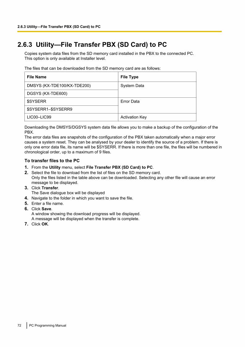
2.6.3 Utility—File Transfer PBX (SD Card) to PCCopies system data files from the SD memory card installed in the PBX to the connected PC.This option is only available at Installer level.
The files that can be downloaded from the SD memory card are as follows:
File Name File Type
DMSYS (KX-TDE100/KX-TDE200) System Data
DGSYS (KX-TDE600)
$SYSERR Error Data
$SYSERR1–$SYSERR9
LIC00–LIC99 Activation Key
Downloading the DMSYS/DGSYS system data file allows you to make a backup of the configuration of thePBX.The error data files are snapshots of the configuration of the PBX taken automatically when a major errorcauses a system reset. They can be analysed by your dealer to identify the source of a problem. If there isonly one error data file, its name will be $SYSERR. If there is more than one file, the files will be numbered inchronological order, up to a maximum of 9 files.
To transfer files to the PC1. From the Utility menu, select File Transfer PBX (SD Card) to PC.2. Select the file to download from the list of files on the SD memory card.
Only the files listed in the table above can be downloaded. Selecting any other file will cause an errormessage to be displayed.
3. Click Transfer.The Save dialogue box will be displayed
4. Navigate to the folder in which you want to save the file.5. Enter a file name.6. Click Save.
A window showing the download progress will be displayed.A message will be displayed when the transfer is complete.
7. Click OK.
72 PC Programming Manual
2.6.3 Utility—File Transfer PBX (SD Card) to PC

2.6.4 Utility—SD Card File View and LoadDisplays a list of files on the SD memory card, and allows you to update the programmes stored in LPR cards(cards with local processors) and Cell Stations (CSs).This option is only available at Installer level.To update the programme stored in an LPR card, the card must first be set to out of service (OUS). To updatethe programme stored in a CS, the port of the card (CSIF/DHLC/DLC) that the CS is attached to must be setto OUS, but the card itself must be set to in service (INS). Only cards that are in the correct status will bedisplayed.The name, date and time of creation, and size of files are displayed.This utility can also display information on activation key files stored in the SD memory card.The effective date, IPCMPR-ID/IPCEMPR-ID, activation key type, number of activation keys, and expirationdate of activation keys are displayed on the Detail screen. The expiration date of preinstalled activation keysis displayed as "Unlimited duration".
To view and load files on the SD memory card1. From the Utility menu, select SD Card File View and Load.2. Click on the name of the desired file.
Only files containing programme data (whose filenames start with "P") can be selected.3. Click Detail.
The Detail screen will be displayed. Header information from the chosen SD memory card file is displayedon the left.
4. From the Card drop-down list on the right, select the card(s) whose software you want to update.• To update a specific card or port:
• LPR cards: select the slot number and card name.• CSs: select the slot number and card name, and then select the related CS port from the drop-down
list directly below.• To update all matching cards simultaneously:
• Select "ALL".5. Click View to update the displayed header information of the selected files.
The file with the higher File Version and File Revision numbers is newer.6. Click Load to update the file stored on the PBX.
When the update is finished, a message will be displayed.7. Click OK.
The display will return to the Detail screen.
To view information on activation key files stored in the SD memory card (Interactive modeonly)1. From the Utility menu, select SD Card File View and Load.2. Click on the name of the desired activation key file.3. Click Detail.
The Detail screen will be displayed.
PC Programming Manual 73
2.6.4 Utility—SD Card File View and Load

2.6.5 Utility—SD Card File DeleteAllows you to delete files from the SD memory card.This option is only available at Installer level.The following essential system files cannot be deleted by this utility:KX-TDE100/KX-TDE200: PMMPR, DMSYSKX-TDE600: PGMPR, DGSYS
To delete files from the SD memory card1. From the Utility menu, select SD Card File Delete.2. Click on the file to be deleted.3. Click Delete.
A confirmation screen will be displayed.4. Click OK.
The display will return to the SD Card File Delete screen.
74 PC Programming Manual
2.6.5 Utility—SD Card File Delete

2.6.6 Utility—Message File Transfer PC to PBXTransfers Outgoing Message (OGM) files from the PC to the selected MSG/ESVM card/block mounted on anOPB/IPCMPR/IPCEMPR card.This option is only available at Installer level.
Note• When transferring to or from an MSG/ESVM card mounted on an OPB card, the OPB card must be
set to OUS status.• When transferring to or from the built-in ESVM block on the IPCMPR/IPCEMPR card, the ESVM block
must be set to OUS status.Files are stored on the MSG/ESVM card/block in the location specified by the file’s header information.Uploaded files are automatically renamed as necessary. If this location already contains an OGM, it will beoverwritten by the newly uploaded message.
To transfer OGMs to an MSG/ESVM card/block1. From the Utility menu, select Message File Transfer PC to PBX.2. Select the target MSG/ESVM card/block, or "ALL", from the drop-down list, and click OK.
The Open dialogue box will be displayed.3. Select the message files to upload.
It is possible to select multiple files.4. Click OK.
The files will be uploaded. Files that do not contain message data will be ignored.When complete, the display will return to the main screen.
PC Programming Manual 75
2.6.6 Utility—Message File Transfer PC to PBX

2.6.7 Utility—Message File Transfer PBX to PCTransfers Outgoing Message (OGM) files from the MSG/ESVM card/block mounted on an OPB/IPCMPR/IPCEMPR card to the PC.This option is only available at Installer level.
Note• When transferring to or from an MSG/ESVM card mounted on an OPB card, the OPB card must be
set to OUS status.• When transferring to or from the built-in ESVM block on the IPCMPR/IPCEMPR card, the ESVM block
must be set to OUS status.
To transfer OGMs to the PC1. From the Utility menu, select Message File Transfer PBX to PC.2. From the upper drop-down list, select the target MSG/ESVM card/block.3. From the lower drop-down list, select the messages to transfer.
• To transfer a certain message, select the number of that message.• To transfer all messages at once, select "ALL".The Save dialogue box will be displayed.
4. Enter a file name.5. Click Save.6. Click OK.
When you choose to transfer all messages, each message is saved as an individual file, with a numberappended to the file name corresponding to that message’s location on the MSG/ESVM card/block.When complete, the display will return to the main screen.
76 PC Programming Manual
2.6.7 Utility—Message File Transfer PBX to PC

2.6.8 Utility—Error LogCollects and displays system error information.Whenever there is a system failure, the PBX stores the error code generated. The connected PC collects allof these codes, along with other information, and displays an explanatory error message.
The functions of the buttons on this screen are as follows:
Button Function
Cancel Closes the Error Log screen without saving.
Capture Saves the currently displayed Error Log information as a text file.
Minor Displays minor errors, which affect only a certain part of systemoperation.
Major Displays major errors, which affect operation of the whole system, orresult in system failure.
Clear Erases the stored error log information from both the screen and thePBX.
Log Information Displays probable causes of the errors and their solutions.
The items displayed on screen are as follows:
Item Description
Index The ordinal number assigned to an error record in the current log.
Date The date of the error detection.
Time The time of the error detection.
Error Code The 3-digit error code assigned by the PBX.
PC Programming Manual 77
2.6.8 Utility—Error Log

Item Description
Sub Code The 6-digit sub code of the relevant hardware (WXYYZZ).• W: Shelf type
– Physical shelf: " " (blank)– Virtual shelf: "*" (asterisk)
• X: Shelf numberKX-TDE100/KX-TDE200: 1KX-TDE600:• 1: Basic Shelf• 2: Expansion Shelf 1• 3: Expansion Shelf 2• 4: Expansion Shelf 3
• YY: Slot number– KX-TDE100 (Physical slot): 00 to 06
(00: IPCMPR Card Slot; 01 to 06: Free Slots)– KX-TDE200 (Physical slot): 00 to 11
(00: IPCMPR Card Slot; 01 to 11: Free Slots)– KX-TDE600 (Physical slot):
• Basic Shelf: 00 to 10(00: IPCEMPR Card Slot; 01 to 10: Free Slots)
• Expansion Shelf: 01 to 12(01 to 11: Free Slots; 12: BUS-S Card Slot)
– KX-TDE100/KX-TDE200/KX-TDE600 (Virtual slot): 00 to 08(00: Built-in ESVM card; 01 to 04: Virtual Trunk Slots; 05 to08: Virtual Extension Slots)
• ZZ: Port number– For optional service cards except OPB3 card:
Port number (01 to 16) will be displayed.– For OPB3 card:
Sub slot number (1 to 3) + port number (1 to 4) will bedisplayed as follows:• Sub slot 1 of OPB3: 11 to 14• Sub slot 2 of OPB3: 21 to 24• Sub slot 3 of OPB3: 31 to 34
NoteWhen there is no parameter for slot and port number, YY and ZZwill be displayed as "00".Example: Sub code for IPCMPR card = " 10000"
Error Message A description of the error.
To view the error log• From the Utility menu, select Error Log.
78 PC Programming Manual
2.6.8 Utility—Error Log
2.6.9 Utility—T1/E1 Signalling Bit MonitorDisplays reference signalling bit information for all channels of the T1 or E1 card, by monitoring sent andreceived A, B, C and D bits. This utility is intended for use by dealers.This option is only available at Installer level, and requires that the target card be set to INS status.While monitoring is being performed, any displayed bits whose value changes from 0 to 1 or vice versa will behighlighted in red until the next screen refresh is performed.
To view signalling bit information1. From the Utility menu, select T1/E1 Signalling Bit Monitor.2. From the Slot No drop-down list, select the target slot.3. From the Interval Timer drop-down list, select the number of seconds between each automatic screen
refresh.4. Click Start.
Monitoring will be performed and the screen will refresh according to the interval specified.5. Click Stop to end monitoring.
To refresh the screen at any time while monitoring is stopped, click Refresh.
PC Programming Manual 79
2.6.9 Utility—T1/E1 Signalling Bit Monitor
2.6.10 Utility—T1/E1 Line TraceTraces the sent and received signalling bits and dial numbers on the specified channel of the T1 or E1 line.This utility is intended for use by dealers.This option is only available at Installer level, and requires that the target card be set to INS status.
To view trace data1. From the Utility menu, select T1/E1 Line Trace.2. From the Slot No drop-down list, select the target slot.3. From the CH No drop-down list, select the target channel.4. Click Start.
Trace information will be displayed. The information is automatically updated whenever the data beingmonitored changes.
5. Click Stop to end the trace.6. Select an option:
• Click Capture to save the displayed trace information.Information is saved as a text-format file.
• Click Clear to erase the information.
80 PC Programming Manual
2.6.10 Utility—T1/E1 Line Trace

2.6.11 Utility—ISDN/QSIG Protocol TraceThis utility collects protocol trace data from BRI, PRI or IP-GW cards, and displays it on the PC.This option is only available at Installer level, and requires that the target BRI, PRI or IP-GW card be set toINS status.Protocol trace data is continually accumulated on ISDN and IP-GW cards, and 3 types of data can bedownloaded:• Real Time Trace: Pseudo-real-time data is collected through data polling at one-second intervals. The
displayed information is updated beginning when the Start button is clicked.• Accumulation Trace: Previously accumulated data is retrieved and displayed.• Error Accumulation Trace: Previously accumulated error data is retrieved and displayed. This trace shows
the data snapshot that is taken just before a card resets.
To view trace data1. From the Utility menu, select ISDN/QSIG Protocol Trace.2. From the Slot No drop-down list, select the target slot.3. From the Trace Data Type drop-down list, select the type of data to view.4. Click Start.
Trace information will be displayed.5. Select an option:
• Click Capture to save the displayed trace information.• Click Clear to clear the screen display.
6. Click Cancel to return to the main screen.
PC Programming Manual 81
2.6.11 Utility—ISDN/QSIG Protocol Trace
2.6.12 Utility—V-IPGW16 Protocol TraceThis utility collects trace data of protocol activity from V-IPGW16 card.This option is only available at Installer level, and requires that the target V-IPGW16 card be set to INS status.
To save trace data to the SD Memory Card1. From the Utility menu, select V-IPGW16 Protocol Trace.
When the progress bar disappears, the protocol trace is complete. The trace data has been saved to theSD Memory Card (file name: "PRTH323").
To transfer trace data to the PC1. From the Utility menu, select File Transfer PBX (SD Card) to PC.
The trace data will be displayed.2. Select the desired trace data file.3. Click Transfer.4. Navigate to the folder in which you want to save the file.5. Enter a file name.6. Click Save.7. Click OK.
82 PC Programming Manual
2.6.12 Utility—V-IPGW16 Protocol Trace

2.6.13 Utility—Digital Trunk Error ReportDisplays accumulated information on various types of errors occurring on digital trunks.This option is only available at Installer level.The value displayed for each error item is the number of times that each error occurred during the time periodselected. Average values for these items vary depending upon many factors, such as the equipment beingused, and the distance from the telephone company.
The displayed items are as follows:
Item Description
Time Time of error
Slot Relevant slot and card type
Counter of Digital TrunkError Logs logged in"Minor Error" Log
Out of SYNC (#300) Digital trunk out of sync (Loss of Signal)
RAI (#301) Digital trunk RAI signal reception
AIS (#302) Digital trunk Alarm Indication Signal reception
Frame Failure (#300) Digital trunk frame failure (Loss of Frame)
Counter of minorcommunication error
CRC Cyclic Redundancy Check error
SF Severely errored frame (or Severe FramingError)
FE Frame synchronisation bit-error
LV Line Code Violation
SL Controlled slip
To view digital trunk information1. From the Utility menu, select Digital Trunk Error Report.2. From the Slot No drop-down list, select the target slot.
• To generate a report on a specific card, select the slot number and card name.• To generate a report on all matching cards simultaneously, select "ALL".
3. From the Display form drop-down list, select the time period to view.4. Click Execute.
The error report will be displayed.
PC Programming Manual 83
2.6.13 Utility—Digital Trunk Error Report

2.6.14 Utility—IP Extension Statistical InformationDisplays accumulated statistical information on IP extensions, IP-EXT cards, V-IPEXT32 cards, V-IPCS4cards, and the DSP card.
The displayed items are as follows:
Item Description
Collection Started Time Date and time the port was last reset.
Port No. Number of the port.
RTP Receive Packet Counter Total number of packets received.
RTP Receive Lost Packet Counter Total number of packets lost.
RTP Receive Abandoned Packet Counter Total number of packets abandoned.
RTP Arrive Packet Interval (MAX.) [ms] Maximum time taken for a packet toarrive.
RTP Arrive Packet Interval (MIN.) [ms] Minimum time taken for a packet toarrive.
To view IP extension information1. From the Utility menu, select IP Extension Statistical Information.2. From the Card Selection drop-down list, select the slot number for the card. "IPCMPR (VoIP-DSP)" can
be selected for the DSP card when DSP Card Status is enabled. See 3.4 [1-1] Slot—Card Property -IPCMPR.
3. Click Execute.The statistical information will be displayed.
4. Select an option:• Click Capture if you want to save the displayed information.
1. Enter a file name, or select a file to overwrite.2. Click Save.
• Click Clear to erase the information and reset the Collection Started Time.5. Click Cancel to return to the main screen.
84 PC Programming Manual
2.6.14 Utility—IP Extension Statistical Information
2.6.15 Utility—CS InformationDisplays information stored by the PBX regarding each Cell Station (CS).This option is only available at Installer level, and requires that the target CSIF, DHLC, DLC, or V-IPCS4 cardbe set to INS status.
The displayed items are as follows:
Item Description
Slot Number of the slot (for KX-TDE600, shelf and slot)
Port Number of the port
CS Name Name of the attached CS
Status Service status of the attached CS: INS, OUS, or FAULT.If the status is FAULT, subsequent data items for that port will be leftblank.
Version Version number of the programme file stored in the CS
Revision Revision number of the programme file stored in the CS
CSID 12-digit ID number of the CS
Path Number of the wireless extension currently using each path. In the caseof a group, several extensions may be using the same floating extensionnumber.When an extension number is not registered, the display shows"OFF". 2.4 GHz PSs can use up to 3 paths. DECT PSs can use up to4 paths. When using high-density CSs or IP-CSs, DECT PSs can useup to 8 paths.
Group Call Number of PSs registered to the attached CS that are members of a PSRing Group.
To view CS information1. From the Utility menu, select CS Information.2. From the Target CSI/F Slot No drop-down list, select the target slot.
• To display information on a single card, select the slot number and name of that card.• To display information on all matching cards, select "All".
3. From the Interval Timer drop-down list, select the number of seconds between each automatic screenrefresh.
4. Click Start to begin monitoring.Monitoring will be performed and the screen will refresh according to the interval specified.To refresh the screen manually at any time, click Refresh.
5. Click Stop to end monitoring.6. Select an option:
• Click Capture if you want to save the displayed information.1. Enter a file name, or select a file to overwrite.2. Click Start.
• Click Close to return to the main screen.
PC Programming Manual 85
2.6.15 Utility—CS Information

2.6.16 Utility—PS InformationDisplays Portable Station (PS) registration information, including the associated Cell Station (CS).This option is only available at Installer level.
The displayed items are as follows:
Item Description
PS No. PS location number.Only registered PSs will be displayed.
Extension Number Extension number of the PS.
Location—Slot Slot number of the CS that the PS is registered with.
Location—Port Port number of the CS that the PS is registered with.
To view PS information1. From the Utility menu, select PS Information.2. Click Refresh.
86 PC Programming Manual
2.6.16 Utility—PS Information
2.6.17 Utility—CS Status MonitorThis utility monitors the status of CSs within Air Synchronisation Groups. CSs receive data from other CSs thatthey are currently synchronised with, within the Air Synchronisation Group. Current Sync CS information isdisplayed for IP-CSs that are in INS status.This option is only available at Installer level.
The displayed items for the Current Sync CS of each CS are as follows:
Item Description
CS Type Type of CS that each CS is currently synchronised with.
Shelf Slot type (shelf) of the CS that each CS is currently synchronised with.
Slot Slot number of the CS that each CS is currently synchronised with.
Port Port number of the CS that each CS is currently synchronised with.
CS / Repeater Indicates whether the CS that each CS is currently synchronised with, is aCS or Repeater.
CS Name Name of the CS that each CS is currently synchronised with.
CS ID 12-digit ID number of the CS that each CS is currently synchronised with.
Monitored Value Monitored value (dBm) of the CS that each CS is currently synchronisedwith.
Monitored Level Monitored level (signal strength level) of the CS that each CS is currentlysynchronised with.
To monitor the status of CSs1. From the Utility menu, select CS Status Monitor.2. From the Air Sync Group No drop-down list, select an Air Synchronisation Group.
• For PMMPR/PGMPR Software File Version 3.0000, only Air Synchronisation Group 1 can be selected.3. From the Interval Timer drop-down list, select the number of seconds between each automatic screen
refresh.4. Click Start to begin monitoring.
Monitoring will be performed and the screen will refresh according to the interval specified.To refresh the screen manually at any time, click Refresh.
5. Click Stop to end monitoring.6. Select an option:
• Click Capture if you want to save the displayed information.1. Enter a file name, or select a file to overwrite.2. Click Start.
• Click Close to return to the main screen.
PC Programming Manual 87
2.6.17 Utility—CS Status Monitor

2.6.18 Utility—PingPerforms a connection test on network devices. This function sends echo requests to a particular IP addressacross an IP network, and displays the result of responses and round-trip time.This option is only available when the Maintenance Console is in Interactive mode.
To perform a Ping test1. Enter a specific IP address in the IP Address box.2. Click Test to perform the test.
The result will be displayed.3. Select an option:
• Click Capture if you want to save the displayed information.1. Enter a file name, or select a file to overwrite.2. Click Save.
• Click Close to return to the Ping screen.
88 PC Programming Manual
2.6.18 Utility—Ping

2.6.19 Utility—File Transfer FTP to IP Equipment—IP-CS/NT400Displays a list of files on the FTP server, and allows you to update the programmes stored in IP-CSs andKX-NT400 IP-PTs.This option is only available at Installer level.It is possible to perform the update in 2 ways:• Manual update• Timed (automatic) update
To update manually:1. From the Utility menu, select File Transfer FTP to IP Equipment, and then either IP-CS or NT400.2. Input the FTP Server Address and File Name.3. Put a check in the Select check boxes of the items to be updated.4. Click Execute.
To set timed update:1. From the Utility menu, select File Transfer FTP to IP Equipment, and then either IP-CS or NT400.2. Input the FTP Server Address and File Name.3. Put a check in the Select check boxes of the items to be updated.4. Click Timed Update.
The Timed Update screen appears. For information on setting this screen, see 2.6.20 Utility—CardSoftware Timed Update.
Note• Cards are automatically set to OUS status during an update, and returned to INS status when the
update is complete.• To display the file version of the file stored on the FTP server, click Load.• To refresh the status of all ports, click Refresh.• Timed updates can only be set for either LPR cards, IP-CSs, or KX-NT400 IP-PTs. They cannot be set
for more than one type of device.
PC Programming Manual 89
2.6.19 Utility—File Transfer FTP to IP Equipment—IP-CS/NT400

2.6.20 Utility—Card Software Timed UpdateUpdates programmes in the LPR cards (optional service cards with local processors) by comparing them withfiles found on the SD memory card on a preset schedule, and downloading newer files to the cards.This option is only available at Installer level.
Note• Timed updates can only be set for either LPR cards, IP-CSs, or KX-NT400 IP-PTs. They cannot be set
for more than one type of device.• Cards are automatically set to OUS status during an update, and returned to INS status when the
update is complete.• It is recommended to set the timed update to take place during the least active time period, for example
late at night.This utility does not apply to CS programmes. These must be updated manually using the SD Card File Viewand Load utility (see 2.6.4 Utility—SD Card File View and Load).When this utility has been set, all commands that would affect the status of cards are prevented from operating.The list of these commands is as follows:• Card status change (INS/OUS)• Diagnosis commands• Card installation• Card deletion• Remote reset• LPR programme download requests• ISDN automatic setup requests (BRI card)• Signalling Bit Monitor requests (T1/E1)• Line trace start requests (T1/E1)• ISDN/QSIG Protocol Data Trace start requests• Time setting• CS programme download requests• File deletionWhen a function other than those listed above, that cannot be performed while timed update has been set, isselected, an error message will be displayed.
To turn this utility on:1. From the Utility menu, select Card Software Timed Update.2. Select the Set option.
The time setting box will become available.3. Enter the desired time using the number keys.
Click in the hour or minute field and use the up and down arrows to adjust the displayed time in incrementsof one unit.
4. Click Apply.A message box will be displayed.
5. Click Yes.
To turn this utility off:1. From the Utility menu, select Card Software Timed Update.2. Select the Off (Cancel) option.3. Click Apply.
A message box will be displayed.4. Click Yes.
90 PC Programming Manual
2.6.20 Utility—Card Software Timed Update

2.6.21 Utility—System Reset—Reset by the CommandUpdates the main system programme and data files stored within the PBX using files taken from the SD memorycard, and resets the connected PBX.This option is only available at Installer level.
Two copies of each of the main system files can be stored on the SD memory card. The names of these filesare as follows:
KX-TDE100/KX-TDE200
File Name Description
DMSYS Main system data file. Contains all of the current configuration data forthe PBX.
DMSYS_S Backup main system data file
PMMPR PBX programme file. Contains the software to run the IPCMPR boardof the PBX.
PMMPR_S Backup PBX programme file
KX-TDE600
File Name Description
DGSYS Main system data file. Contains all of the current configuration data forthe PBX.
DGSYS_S Backup main system data file
PGMPR PBX programme file. Contains the software to run the IPCEMPR boardof the PBX.
PGMPR_S Backup PBX programme file
When new DMSYS/DGSYS and PMMPR/PGMPR files are transferred from a connected PC to the SD memorycard using the File Transfer PC to PBX (SD Card) utility (see 2.6.2 Utility—File Transfer PC to PBX (SDCard)), they are stored as the backup files. To use these files on the PBX, it is necessary to first swap themwith the currently active files on the SD memory card.
To update system files and reset the PBX1. From the Utility menu, point to System Reset and then click Reset by the Command.2. Choose whether to back up current system data or not.
• Click SD Backup to back up the current system data to the SD memory card before proceeding.Select this if you intend to use the current system data unchanged after reset.
• Click Skip to continue without backing up.Select this if you intend to replace the current system data with data that was uploaded from the PC.
The second screen will be displayed. A list of matching files found on the SD memory card, with dates andtimes, is shown at the top.
3. Select whether to replace the DMSYS/DGSYS and PMMPR/PGMPR files or not.When no backup file is found, the corresponding options are not available.
4. Click OK.A confirmation screen will be displayed.
5. Select an option:• Click OK to reset the PBX.
If OK is clicked, a final confirmation screen will be displayed.
PC Programming Manual 91
2.6.21 Utility—System Reset—Reset by the Command

• Click Cancel to return to the main screen without copying files.6. Click OK to reset the PBX, or Cancel to return to the main screen without copying files.
If the reset command was not carried out correctly, an error message will be displayed, and you will bereturned to the main screen.
After resetting the PBX with this command, it is necessary to reconnect to the PBX to continue programming.
92 PC Programming Manual
2.6.21 Utility—System Reset—Reset by the Command

2.7 Help
2.7.1 Frequently Asked Questions (FAQ)This section provides answers to some common questions about using the Maintenance Console software toprogramme the PBX. The information is divided into the following topics:
Title Description
Connection Connecting to the PBX using Maintenance Console.
Maintenance Console Software Using the Maintenance Console software.
Card Status Changing the status (INS/OUS) of cards.
Portable Stations Setting up portable stations, including registration and deregistration.
Numbering Changing the numbering plan for the PBX, or numbers of individualextensions or features.
Saving Modified Data Safely saving PBX data edited with Maintenance Console.
Setting Features Setting up individual features.
ConnectionQ The Maintenance Console cannot connect to the PBX via RS-232C cable.
A • Is the cable firmly connected to both the PC and the PBX?• Is the serial port that the PC uses correctly specified?• Is the baud rate correct?
The default setting, and a safe rate, is 19 200 bps.• Is the password correct?• Is the Maintenance Console not connected to the PBX by another connection method?
Q The Maintenance Console cannot connect to the PBX via USB.
A • Is the USB cable firmly connected to both the PC and the KX-DT300 series/KX-T7600 series DPT with a USB Module?
• Is the USB driver on the PC running?To confirm, open the Windows Device Manager, and look for "Panasonic KX-TDA USBMain Unit driver" in the USB Controllers section. If it is not present, re-install the USBdriver
• Is the password correct?• Is the Maintenance Console not connected to the PBX by another connection method?
Q The Maintenance Console cannot connect to the PBX via LAN.
A • Is the PC connected to the LAN?• Have the IP address and port number of the PBX been set correctly? For more details,
see 3.4 [1-1] Slot—Card Property - IPCMPR.• Is the password correct?• Is the Maintenance Console not connected to the PBX by another connection method?
PC Programming Manual 93
2.7.1 Frequently Asked Questions (FAQ)

Q The Maintenance Console cannot connect to the PBX via modem.
A • Is the dial number of the modem correct? For more details, see 13.1 [11-1] Main.• Has a modem been installed to the PBX?• Are the modem settings of the PBX and Maintenance Console correct? For more
details, see 13.1 [11-1] Main.• Is the password correct?• Is the Maintenance Console not connected to the PBX by another connection method?
Q The Maintenance Console cannot connect to the PBX via ISDN Remote.
A • Are the ISDN Remote settings of the PC correct? For more details, see 13.1 [11-1]Main.
• Is the ISDN Remote dial number correct?• Is the password correct?• Is the Maintenance Console not connected to the PBX by another connection method?
Q Can I perform initial setup of the PBX without being connected to the PBX?
A • Yes. This is possible in Batch mode.Create a new system data file using 2.2.1 Programme launcher—New, edit settingsas required, and then upload this file to the PBX later (see 2.6.2 Utility—File TransferPC to PBX (SD Card)).
Maintenance Console SoftwareQ How do I confirm the software version of the PBX or installed cards?
A • From 3.1 [1-1] Slot, click Summary. Summary information, including softwareversions, is displayed for all cards installed in the PBX.
Q Not all of the characters of a setting can be displayed because the column is toonarrow.
A • Move the mouse to the line between the names of 2 setting items, at the top of thetable.The pointer will change to a double arrow. Click and drag the line to the right until allcharacters are displayed.
Card StatusQ The status of a new card will not change to "INS".
A • With the new card installed, does the total number of extensions or trunks exceed themaximum supported by the PBX?
• Is the type of card installed in the slot different from the card type set as "Pre-install"for that slot? Confirm that the correct card is installed in the slot.
• Is the card firmly and fully installed in the slot? Confirm that the card is installedcorrectly in the slot.
• Confirm that the card is not damaged.
Q I want to set the status of only 1 port of the IP-GW4 card to "OUS".
94 PC Programming Manual
2.7.1 Frequently Asked Questions (FAQ)

A • This cannot be done, since the IP-GW4 card requires both channels of a port to beset to "OUS"/"INS" together.
Q I cannot change an LCO port to INS status.
A • Is the card installed in the appropriate slot?• Is the card installed in the correct slot, but not functioning correctly?
Check the condition of the card.• Is the card itself in INS status?
Set it to INS status.• Is a trunk line connected to the appropriate port?• Is the port in FAULT status, even though a trunk is connected?
Run diagnosis on the relevant slot.
Q How do I prevent newly installed cards automatically being changed to "INS"?
A • Change New Card Installation—Card Status for any Card in 3.62 [1-3]Option from "In Service (INS)" to "Out of Service (OUS)".
Portable StationsQ I cannot register Portable Stations using the method described in Portable Station
[1-2].
A • Is the status of the CSIF, DHLC or DLC card set to "INS"?• Is a CS connected to the CSIF, DHLC or DLC card? If not, connect one.• Do the PINs (Personal Identification Numbers) of the PBX and the Portable Station
match? Confirm that they are the same.• Is the Portable Station within transmission range of the CS?• Has the Portable Station previously been registered at another location?
It is not possible to register a Portable Station at 2 locations, so use the ForcedDe-registration option to delete the previous registration.
Q I cannot delete the extension number of a Portable Station.
A • First, de-register the Portable Station itself, and then delete the extension number.
Q I cannot de-register a Portable Station.
A • Is the Portable Station turned on? If not, turn it on.• Is the Portable Station within transmission range of the CS? If not, move it closer to
the CS and try the de-registration operation again.
Q The Portable Station I want to de-register is broken, and will not turn on, or is notavailable, or the registration information was deleted first from the Portable Station,so it cannot be de-registered.
A • The Portable Station can be forcibly de-registered by following the procedure shownin Forced De-registration of 3.61 [1-2] Portable Station.
Q I changed the extension number of a Portable Station, but the display of the PortableStation still shows the old extension number.
A • Turn the Portable Station off and back on again, to force it to re-register its location.
PC Programming Manual 95
2.7.1 Frequently Asked Questions (FAQ)

Q I changed the FCO of a Portable Station, but the display of the Portable Station stillshows the old FCO.
A • Turn the Portable Station off and back on again, to force it to re-register its location.
Q If I delete the extension number of a Portable Station, and then turn the PortableStation off and back on again, it does not function correctly.
A • Do not delete the extension number of the Portable Station, as this information isnecessary for it to operate.
NumberingQ How do I change the extension number of a wired extension?
A • Change the extension number of the target port to the new number, and click Apply.Next, set the port to OUS status, and then back to INS status.
Q I changed the extension number of a wired extension while the extension wasengaged in a call, but the display still shows the previous extension number.
A • The extension number will not change while the extension is in use. When theconversation is finished, set the port to OUS status, and then back to INS status.
Q How do I change the extension numbering plan from 3-digit numbers to 4-digitnumbers?
A • Perform the following steps:1. Open the 4.9 [2-6-1] Numbering Plan—Main screen.2. Enter a 2-digit number in Leading Number, or change No. of Additional
Digits from "x" to "xx".For more details, see What is the procedure to modify the Numbering Plan?in Numbering.
Q How do I set a 3-digit numbering plan?
A • There are 2 methods of creating a 3-digit numbering plan, using 4.9 [2-6-1]Numbering Plan—Main:1. Set the leading number to be 2 digits, with one additional digit. This method allows
a maximum of 10 extensions.Example: Leading Number = 10; No. of Additional Digits = xIn this example, extension numbers 100 to 109 can be used.
2. Set the leading number to be one digit, with 2 additional digits. This method allowsa maximum of 100 extensions.Example: Leading Number = 1; No. of Additional Digits = xxIn this example, extension numbers 100 to 199 can be used.
For more details, see What is the procedure to modify the Numbering Plan? inNumbering.
Q What is the procedure to modify the Numbering Plan?
96 PC Programming Manual
2.7.1 Frequently Asked Questions (FAQ)

A • Perform the following steps:1. Confirm that the Numbering Plan you will change is not currently being used by
any extensions (see 2.5.8 Tool—Extension List View).If it is being used by extensions, temporarily change the extension numbers ofthose extensions to that of another numbering plan, or delete the extensionnumber (see 6.1 [4-1-1] Wired Extension—Extension Settings and6.10 [4-2-1] Portable Station—Extension Settings).
2. Clear the Leading Number cell.3. Click Apply.4. Modify the No. of Additional Digits cell as required.5. Click Apply.6. Enter the desired value in the Leading Number cell.7. Click Apply.8. Set all extension ports to OUS status.9. On the relevant screens, set the extension numbers of extensions to the desired
values.10. Set all extension ports back to INS status.
Q When modifying the Numbering Plan, I cannot change the Leading Number.
A • It is not possible to use the same Leading Number for 2 extension blocks, or to use anumber that could possibly overlap with another Leading Number.So, for example, if "2" is already set as a Leading Number it is not possible to set"21" as another Leading Number because of the possible overlap of extensionnumbers.The number you are trying to store cannot be used if it is already being used by:• A feature number• Another extension block• A Dial setting (see 11.1 [9-1] TIE Table)• Quick Dialling (see 4.10 [2-6-2] Numbering Plan—Quick Dial)In any of these cases, choose another number.
Q When modifying the Numbering Plan, how do I set a 1-digit extension number?
A • Perform the following steps:1. Clear the Leading Number cell.2. Click Apply.3. Set No. of Additional Digits to "None".4. Click Apply.5. Enter the desired value in the Leading Number cell.6. Click Apply.7. Set all extension ports to OUS status.8. On the relevant screens, set the extension numbers of extensions to the desired
values.9. Set all extension ports back to INS status.
Q How do I change a feature number?
A • Perform the following steps:1. Open the 4.9 [2-6-1] Numbering Plan—Main screen.2. Change the value in the Dial cell of the desired feature.3. Click Apply.
PC Programming Manual 97
2.7.1 Frequently Asked Questions (FAQ)
Q I cannot change a feature number.
A • It is not possible to use the same number for 2 items.The number you are trying to store cannot be used if it is already being used by:• A feature number• An extension• A Dial setting (see 11.1 [9-1] TIE Table)• Quick Dialling (see 4.10 [2-6-2] Numbering Plan—Quick Dial)In any of these cases, choose another number.
Q How do I change the code used to access another PBX?
A • Perform the following steps:1. Open the 4.9 [2-6-1] Numbering Plan—Main screen.2. Select the Other PBX Extension tab.3. Change the value in the Dial cell of the desired feature.4. Click Apply.
Q I cannot change an Other PBX Extension code.
A • It is not possible to use the same number for 2 items.The number you are trying to store cannot be used if it is already being used by:• A feature number• An extension• A Dial setting (see 11.1 [9-1] TIE Table)• Quick Dialling (see 4.10 [2-6-2] Numbering Plan—Quick Dial)In any of these cases, choose another number.
Q I cannot change a feature number on the B/NA DND Call Feature screen.
A • The number you are trying to store is already being used by another call feature.Please choose a different number.
Q How do I prevent extension numbers being automatically assigned to a newlyinstalled card?
A • Change New Card Installation—Automatic Extension Number Set forExtension Card in the 3.62 [1-3] Option screen from "Automatic" to "Manual".
Saving Modified DataQ Modified settings have not been updated in the PBX.
A • Click Apply or OK in the sub-menu screen.
Q Modified settings are not saved even when I press the Apply button.
A • To save the system data files, choose Save from the File menu.
Q If I reset the PBX directly after modifying settings, the modified settings are notupdated in the PBX.
98 PC Programming Manual
2.7.1 Frequently Asked Questions (FAQ)

A • When you click Apply, the settings are updated in the PBX, but are not yet saved tothe SD memory card. If system data is not saved to the SD memory card, the PBX willrestore the data that was last saved to the card in the event that the PBX is reset, orpower is turned off and back on again.Therefore, before resetting the PBX, click the SD memory backup icon to save thesystem data to the SD memory card. Alternatively, exit the Maintenance Console. Thisautomatically saves system data to the SD memory card.
NoteDo not remove the SD memory card while power is supplied to the PBX. Doing somay cause the PBX to fail to start when you try to restart the system.
Q After reinitialising the PBX, I restored system data from a previous backup.However, some of the settings have not been restored to their previous values.
A • The following setting data is not saved to the SD memory card, so will be deleted whenthe PBX is initialised. This data is stored in the PBX’s battery backup memory.• Incoming Call Log• Outgoing Call Log (including Last Number Redial)• Message Waiting• SMDR• Advice of Charge (AOC)/Pay Tone• Hospitality guest billing data• ICD Group monitor log for supervisor• PBX date and time• Timed Reminder• LPR Timed Update time• PT handset/headset volume• PT SP-PHONE volume• PT ring volume• PT display contrast• ICD Group login status
(All extensions are set to Login by default.)• ICD Group Ready/Not Ready status
(All extensions are set to Ready by default.)• Live Call Screening (LCS) On/Off• Hands-free Answerback status• Absent Message status of extensions
(Absent Message data itself is not cleared.)• FWD/DND status
(FWD destinations are not cleared.)• Extension Dial Lock/Remote Extension Dial Lock• Extension PIN Lock/Extension PIN Lock counter• Verification Code PIN Lock/Verification Code PIN Lock counter• Password Lock counter for Remote System Programming• PBX Error Log• Digital Trunk Error Report dataIn addition, the following data cannot be restored:• SVM Log and messages (both greeting messages and voice messages left by
callers) recorded by the SVM feature.
PC Programming Manual 99
2.7.1 Frequently Asked Questions (FAQ)

Setting FeaturesQ How do I change the dialling mode of an analogue trunk?
A • From the 3.30 [1-1] Slot—Port Property - LCO Port screen, change the DiallingMode setting of the target port to "DTMF" or "Pulse", as required.
Q How do I set disconnect detection (CPC Detection) for an analogue trunk?
A • From the 3.30 [1-1] Slot—Port Property - LCO Port screen, modify the CPCSignal Detection Time—Outgoing, Incoming setting of the target port.The required value varies by carrier. Transmission and reception can be setseparately.
Q What settings do I change to enable use of an extension ISDN telephone?
A • From the 3.33 [1-1] Slot—Port Property - BRI Port screen, set the Port Type ofthe port you want to use to "Extension".
Q When using a TE with an extension ISDN, how do I enable power output?
A • From the 3.33 [1-1] Slot—Port Property - BRI Port screen, set ISDN TE Poweron the ISDN Extension tab to "Enable".
Q How do I connect to another PBX using QSIG?
A • From the 3.33 [1-1] Slot—Port Property - BRI Port or 3.35 [1-1] Slot—PortProperty - PRI Port screen, set the Port Type of the port you want to use to either"QSIG-Slave" or "QSIG-Master".
Q How do I change the type of an extension port?
A • Set the port to OUS status. Then, change DPT Type—Type in the 3.24 [1-1] Slot—Port Property - Extension Port window
Q I have set the type of an extension port to "DSS Console", but I cannot apply thissetting. (Error E000402)
A • The number entered in DPT Type—Location No. on the 3.24 [1-1] Slot—PortProperty - Extension Port screen is the same as that entered for another DSSConsole. Change this so that the numbers do not overlap.
Q I have set the type of an extension port to "VM (DPT)", but I cannot apply this setting.(Error E000403)
A • The DPT Type—VM Unit No. and DPT Type—VM Port No. settings entered onthe 3.24 [1-1] Slot—Port Property - Extension Port screen are the same as thoseentered for another VM (DPT). Change this so that the numbers do not overlap.
Q I have set the type of an extension port to "PC Console", but I cannot apply thissetting. (Error E000402)
A • The number entered in DPT Type—Location No. on the 3.24 [1-1] Slot—PortProperty - Extension Port screen is the same as that entered for another PC Console.Change this so that the numbers do not overlap.
100 PC Programming Manual
2.7.1 Frequently Asked Questions (FAQ)

Q What programming do I have to perform to use a headset with an extension?
A • Set Headset OFF/ON on the 3.24 [1-1] Slot—Port Property - Extension Portscreen to "Headset ON".
Q What programming do I have to perform to use XDP with an extension port?
A • Set XDP Mode on the 3.24 [1-1] Slot—Port Property - Extension Port screen to"On".
Q How do I edit a Class of Service, or create a new Class of Service?
A • Class of Service feature restrictions can be set from the 4.12 [2-7-1] Class of Service—COS Settings screen.
Q How do I restrict calls between 2 extensions?
A • Calls between extensions can be restricted from the 4.14 [2-7-3] Class of Service—Internal Call Block screen. Click in the relevant cells to select the COS levels whoseextensions are blocked from calling each other.
Q How do I restrict trunk calls made by extensions?
A • Trunk calls made by extensions can be restricted from the 4.13 [2-7-2] Class ofService—External Call Block screen. Click in the relevant cells to select the trunkgroups that cannot be used by extensions associated with a particular COS in eachtime mode.To prevent extensions associated with a COS from making trunk calls, set all trunkgroups for that COS to "Block" (blue).
Q How do I modify the hold operation for SLTs?
A • It is possible to choose how to hold a line and transfer a call with an SLT using the SLT—SLT Hold Mode option on the 4.18 [2-9] System Options screen.For more details, see "1.13.1 Call Hold" of the Feature Guide.
Q How do I set up an Incoming Call Distribution (ICD) group to receive trunk callsdirectly?
A • Perform the following steps:1. On the 5.13 [3-5-1] Incoming Call Distribution Group—Group Settings screen,
enter the floating extension number you chose for the ICD group in the FloatingExtension Number cell.
2. Click Apply.3. On the 5.14 [3-5-1] Incoming Call Distribution Group—Group Settings—
Member List screen, select the ICD group you created from the Incoming CallDistribution drop-down list.
4. Enter the extension numbers of member extensions in the ExtensionNumber column.
5. Click Apply.6. On the DIL tab of the 12.2 [10-2] DIL Table & Port Settings screen, enter the
floating extension number of the ICD group as the DIL Destination—Day,Lunch, Break, Night of each time mode.
7. Modify other settings as required from the Group—Incoming Call DistributionGroup submenu.
PC Programming Manual 101
2.7.1 Frequently Asked Questions (FAQ)

Q How do I set the queuing operation for an Incoming Call Distribution group?
A • Perform the following steps:1. On the 5.15 [3-5-2] Incoming Call Distribution Group—Queuing Time Table
screen, set the actions as required for each queuing table.2. On the 5.13 [3-5-1] Incoming Call Distribution Group—Group Settings screen,
from the Queuing Time Table tab, select the number of the Queuing Time Tableto use in each time mode.
Q How do I add an extension as a member of an Incoming Call Distribution (ICD)group?
A • Perform the following steps:1. On the 5.14 [3-5-1] Incoming Call Distribution Group—Group Settings—
Member List screen, from the Incoming Call Distribution drop-down list, selectthe group you want to modify.The ICD group must have an extension number set.
2. Enter the extension number of the extension you want to add in a blank cell of theExtension Number column.
3. Set Delayed Ring as necessary.4. Click Apply.
Note that it is necessary to set the extension number of the ICD group in advance.
Q I cannot set system speed dialling numbers from PC Console.
A • Set the COS of the extension to which PC Console is connected to Manager class, bysetting Manager on the Extension Feature tab of the 4.12 [2-7-1] Class ofService—COS Settings screen to "Enable".
• System speed dialling numbers can only be edited by one PC Console at a time.
Q I have set FWD through system programming, but calls are still not being forwarded.
A • Perform the following steps:1. Check that the Forward / DND settings of the target extension on the 6.3 [4-1-2]
Wired Extension—FWD/DND or 6.12 [4-2-2] Portable Station—FWD/DNDscreen are set to one of the forwarding settings.
2. Create a FWD button on the target extension if one does not already exist.3. Press the FWD button so that it changes to FWD status.
102 PC Programming Manual
2.7.1 Frequently Asked Questions (FAQ)

Section 3
[1] Configuration
PC Programming Manual 103

3.1 [1-1] SlotThe operating characteristics associated with each service card can be programmed.Move the mouse pointer over an installed card to display the menu of options for that card. To view a summaryof status and MPR versions for all cards installed in the PBX, click the Summary button (see 3.2 [1-1] Slot—Summary).
To install a new card to the PBX1. Click on the name of the card to install in the list on the right.
An image of the card will be displayed to the left of the list, and information about the card will be shownbelow.
2. Click and drag the image of the card to the free slot it is to be installed in, and release it.The card will move into the slot space.
3. Click Yes to confirm.
To switch between physical and virtual shelves of the PBX1. Move the mouse pointer over the white PBX image at the bottom of the screen for the virtual slots.
Select Shelf will be shown under the mouse pointer.2. Click Select Shelf.
To install a new shelf to the PBX (KX-TDE600 only)1. Move the mouse pointer over the first greyed PBX image at the bottom of the screen.
Pre-Install will be shown under the mouse pointer.2. Click Pre-Install.3. Click Yes to confirm.
To select a different shelf of the PBX (KX-TDE600 only)1. Move the mouse pointer over the white PBX image at the bottom of the screen for the Expansion Shelf
you wish to select.Select Shelf will be shown under the mouse pointer.
2. Click Select Shelf.
To access card properties1. Move the mouse pointer over a card.
A menu will be shown under the mouse pointer.2. Select Card Property.
The property screen for that card will be displayed.
To access port properties1. Move the mouse pointer over a card.
A menu will be shown under the mouse pointer.2. Select Port Property.
The property screen for that card’s port or ports will be displayed.
104 PC Programming Manual
3.1 [1-1] Slot

To remove a card from the PBX1. Move the mouse pointer over the card to remove.
A menu will be shown under the mouse pointer.2. Select Delete.3. Click Yes to confirm.
The card will be removed.
To change the status (INS/OUS) of a card (Interactive mode only)1. Move the mouse pointer over the card.
A menu will be shown under the mouse pointer.2. Select the desired status:
• Click INS to set the card to in-service status.• Click OUS to set the card to out-of-service status.
To install an option card on an OPB3 card1. Move the mouse pointer over the card.
A menu will be shown under the mouse pointer.2. Select Option Card.
The OPB3 Option Card Setup screen will be displayed. See 3.60 [1-1] Slot—OPB3 Option CardSetup.
To access IP-PT port properties1. Click the IP Phone Registration button.
Supported Card TypesKX-TDE100/KX-TDE200
Card Maximum Quantity Card Programming
IPCMPR: IP Convergence MainProcessing Card 1 (fixed in Slot 00) 3.4 [1-1] Slot—Card Property -
IPCMPR
PC Programming Manual 105
3.1 [1-1] Slot
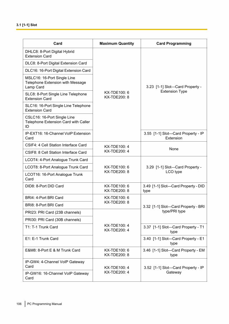
Card Maximum Quantity Card Programming
DHLC8: 8-Port Digital HybridExtension Card
KX-TDE100: 6KX-TDE200: 8
3.23 [1-1] Slot—Card Property -Extension Type
DLC8: 8-Port Digital Extension Card
DLC16: 16-Port Digital Extension Card
MSLC16: 16-Port Single LineTelephone Extension with MessageLamp Card
SLC8: 8-Port Single Line TelephoneExtension Card
SLC16: 16-Port Single Line TelephoneExtension Card
CSLC16: 16-Port Single LineTelephone Extension Card with CallerID
IP-EXT16: 16-Channel VoIP ExtensionCard
3.55 [1-1] Slot—Card Property - IPExtension
CSIF4: 4 Cell Station Interface Card KX-TDE100: 4KX-TDE200: 4 None
CSIF8: 8 Cell Station Interface Card
LCOT4: 4-Port Analogue Trunk Card
KX-TDE100: 6KX-TDE200: 8
3.29 [1-1] Slot—Card Property -LCO type
LCOT8: 8-Port Analogue Trunk Card
LCOT16: 16-Port Analogue TrunkCard
DID8: 8-Port DID Card KX-TDE100: 6KX-TDE200: 8
3.49 [1-1] Slot—Card Property - DIDtype
BRI4: 4-Port BRI Card KX-TDE100: 6KX-TDE200: 8
3.32 [1-1] Slot—Card Property - BRItype/PRI type
BRI8: 8-Port BRI Card
PRI23: PRI Card (23B channels)
KX-TDE100: 4KX-TDE200: 4
PRI30: PRI Card (30B channels)
T1: T-1 Trunk Card 3.37 [1-1] Slot—Card Property - T1type
E1: E-1 Trunk Card 3.40 [1-1] Slot—Card Property - E1type
E&M8: 8-Port E & M Trunk Card KX-TDE100: 6KX-TDE200: 8
3.46 [1-1] Slot—Card Property - EMtype
IP-GW4: 4-Channel VoIP GatewayCard KX-TDE100: 4
KX-TDE200: 43.52 [1-1] Slot—Card Property - IP
GatewayIP-GW16: 16-Channel VoIP GatewayCard
106 PC Programming Manual
3.1 [1-1] Slot

Card Maximum Quantity Card Programming
OPB3: Optional 3-Slot Base Card KX-TDE100: 4KX-TDE200: 4
3.58 [1-1] Slot—OPB3 CardProperty
V-IPEXT32: Virtual 32-Channel VoIPExtension Card
KX-TDE100: 4KX-TDE200: 4
3.14 [1-1] Slot—Card Property -Virtual IP Extension
V-SIPEXT32: Virtual 32-Channel SIPExtension Card
KX-TDE100: 4KX-TDE200: 4
3.17 [1-1] Slot—Card Property -Virtual SIP Extension
V-IPGW16: Virtual 16-Channel VoIPGateway Card
KX-TDE100: 2KX-TDE200: 2
3.9 [1-1] Slot—Shelf Property -Virtual IP Gateway
V-IPCS4: Virtual 4 IP Cell StationInterface Card
KX-TDE100: 4KX-TDE200: 4
3.20 [1-1] Slot—Card Property -Virtual IPCS
For more information on the IPCMPR card, virtual cards and other optional cards, see the following sectionsin the KX-TDE100/KX-TDE200 Installation Manual:→ 1.3.1 Optional Equipment→ 3.3.1 IPCMPR Card→ 3.4.1 Virtual Cards
KX-TDE600
Card Maximum Quantity Card Programming
IPCEMPR: IP Convergence MainProcessing Card
1 (fixed in Slot 11) 3.4 [1-1] Slot—Card Property -IPCMPR
DHLC8: 8-Port Digital HybridExtension Card
40
3.23 [1-1] Slot—Card Property -Extension Type
DLC8: 8-Port Digital Extension Card
DLC16: 16-Port Digital Extension Card
EMSLC16: 16-Port Single LineTelephone Extension with MessageLamp Card
SLC8: 8-Port Single Line TelephoneExtension Card
ESLC16: 16-Port Single LineTelephone Extension Card
CSLC16: 16-Port Single LineTelephone Extension Card with CallerID
ECSLC24: 24-Port Single LineTelephone Extension Card with CallerID
IP-EXT16: 16-Channel VoIP ExtensionCard
3.55 [1-1] Slot—Card Property - IPExtension
CSIF4: 4 Cell Station Interface Card16 None
CSIF8: 8 Cell Station Interface Card
PC Programming Manual 107
3.1 [1-1] Slot
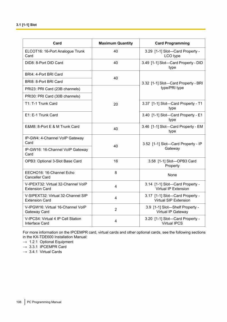
Card Maximum Quantity Card Programming
ELCOT16: 16-Port Analogue TrunkCard
40 3.29 [1-1] Slot—Card Property -LCO type
DID8: 8-Port DID Card 40 3.49 [1-1] Slot—Card Property - DIDtype
BRI4: 4-Port BRI Card40
3.32 [1-1] Slot—Card Property - BRItype/PRI type
BRI8: 8-Port BRI Card
PRI23: PRI Card (23B channels)
20
PRI30: PRI Card (30B channels)
T1: T-1 Trunk Card 3.37 [1-1] Slot—Card Property - T1type
E1: E-1 Trunk Card 3.40 [1-1] Slot—Card Property - E1type
E&M8: 8-Port E & M Trunk Card 40 3.46 [1-1] Slot—Card Property - EMtype
IP-GW4: 4-Channel VoIP GatewayCard
40 3.52 [1-1] Slot—Card Property - IPGatewayIP-GW16: 16-Channel VoIP Gateway
Card
OPB3: Optional 3-Slot Base Card 16 3.58 [1-1] Slot—OPB3 CardProperty
EECHO16: 16-Channel EchoCanceller Card
8 None
V-IPEXT32: Virtual 32-Channel VoIPExtension Card 4 3.14 [1-1] Slot—Card Property -
Virtual IP Extension
V-SIPEXT32: Virtual 32-Channel SIPExtension Card 4 3.17 [1-1] Slot—Card Property -
Virtual SIP Extension
V-IPGW16: Virtual 16-Channel VoIPGateway Card 2 3.9 [1-1] Slot—Shelf Property -
Virtual IP Gateway
V-IPCS4: Virtual 4 IP Cell StationInterface Card 4 3.20 [1-1] Slot—Card Property -
Virtual IPCS
For more information on the IPCEMPR card, virtual cards and other optional cards, see the following sectionsin the KX-TDE600 Installation Manual:→ 1.2.1 Optional Equipment→ 3.3.1 IPCEMPR Card→ 3.4.1 Virtual Cards
108 PC Programming Manual
3.1 [1-1] Slot

3.2 [1-1] Slot—SummarySummary information is displayed for all cards installed in the PBX.For the KX-TDE600, when the PBX has more than two shelves, click a tab to select the shelves to view.
Physical ShelfNo.Indicates the slot number (reference only).
Value RangeAvailable slot numbers.
Maintenance Console Location3.2 [1-1] Slot—Summary
Programming Manual References3.1 [1-1] Slot
Feature Guide ReferencesNone
Card TypeIndicates the type of service card installed in each slot of the physical shelf (reference only). Note that forIPCMPR/IPCEMPR cards, the PBX model code is displayed in parentheses after the name.
Value RangeCard Type for KX-TDE100/KX-TDE200:DHLC8: 8-Port Digital Hybrid Extension CardDLC16: 16-Port Digital Extension CardDLC8: 8-Port Digital Extension CardMSLC16: 16-Port Single Line Telephone Extension Card with Message Lamp CardSLC8: 8-Port Single Line Telephone Extension CardSLC16: 16-Port Single Line Telephone Extension CardCSLC16: 16-Port Single Line Telephone Extension Card with Caller IDCSI/F: 8 or 4 Cell Station Interface CardLCOT16: 16-Port Analogue Trunk CardLCOT8: 8-Port Analogue Trunk CardLCOT4: 4-Port Analogue Trunk CardBRI8: 8-Port BRI CardBRI4: 4-Port BRI CardPRI23: PRI CardPRI30: PRI CardT1: T-1 Trunk CardE1: E-1 Trunk CardE&M8: 8-Port E & M Trunk CardDID8: 8-Port DID CardIP-GW4: 4-Channel VoIP Gateway Card
PC Programming Manual 109
3.2 [1-1] Slot—Summary
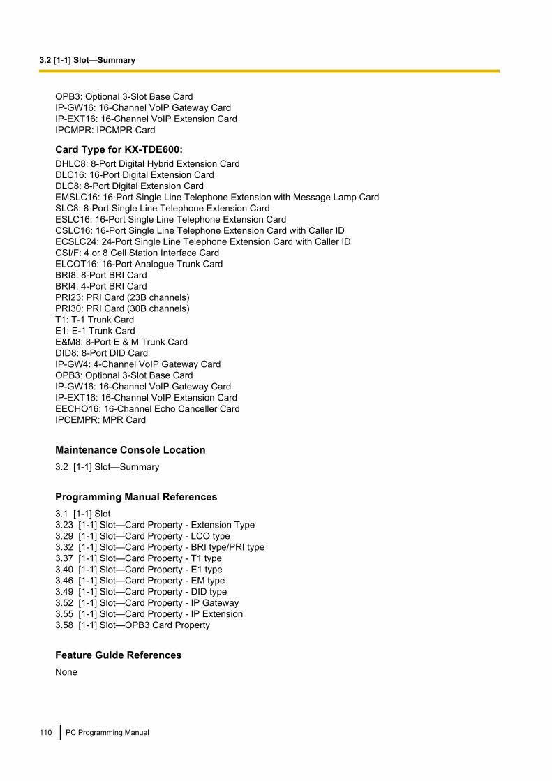
OPB3: Optional 3-Slot Base CardIP-GW16: 16-Channel VoIP Gateway CardIP-EXT16: 16-Channel VoIP Extension CardIPCMPR: IPCMPR Card
Card Type for KX-TDE600:DHLC8: 8-Port Digital Hybrid Extension CardDLC16: 16-Port Digital Extension CardDLC8: 8-Port Digital Extension CardEMSLC16: 16-Port Single Line Telephone Extension with Message Lamp CardSLC8: 8-Port Single Line Telephone Extension CardESLC16: 16-Port Single Line Telephone Extension CardCSLC16: 16-Port Single Line Telephone Extension Card with Caller IDECSLC24: 24-Port Single Line Telephone Extension Card with Caller IDCSI/F: 4 or 8 Cell Station Interface CardELCOT16: 16-Port Analogue Trunk CardBRI8: 8-Port BRI CardBRI4: 4-Port BRI CardPRI23: PRI Card (23B channels)PRI30: PRI Card (30B channels)T1: T-1 Trunk CardE1: E-1 Trunk CardE&M8: 8-Port E & M Trunk CardDID8: 8-Port DID CardIP-GW4: 4-Channel VoIP Gateway CardOPB3: Optional 3-Slot Base CardIP-GW16: 16-Channel VoIP Gateway CardIP-EXT16: 16-Channel VoIP Extension CardEECHO16: 16-Channel Echo Canceller CardIPCEMPR: MPR Card
Maintenance Console Location3.2 [1-1] Slot—Summary
Programming Manual References3.1 [1-1] Slot3.23 [1-1] Slot—Card Property - Extension Type3.29 [1-1] Slot—Card Property - LCO type3.32 [1-1] Slot—Card Property - BRI type/PRI type3.37 [1-1] Slot—Card Property - T1 type3.40 [1-1] Slot—Card Property - E1 type3.46 [1-1] Slot—Card Property - EM type3.49 [1-1] Slot—Card Property - DID type3.52 [1-1] Slot—Card Property - IP Gateway3.55 [1-1] Slot—Card Property - IP Extension3.58 [1-1] Slot—OPB3 Card Property
Feature Guide ReferencesNone
110 PC Programming Manual
3.2 [1-1] Slot—Summary
StatusIndicates the card status (reference only)Note that IPCMPR/IPCEMPR card status is always displayed as "-".
Value RangeINS: The port is in service.OUS: The port is out of service.Fault: The port is not communicating with the network.Pre-Install: A card has been added to the slot.Idle: No card is installed in the slot.
Maintenance Console Location3.2 [1-1] Slot—Summary
Programming Manual References3.1 [1-1] Slot
Feature Guide ReferencesNone
VersionIndicates the LPR version of the installed card (reference only).For IP-EXT cards, both the LPR version and the VoIP version are displayed. The LPR version is shown on theleft, and the VoIP version on the right, as follows:(Example) 1.002 / 1.001
Value RangeVersion number
Maintenance Console Location3.2 [1-1] Slot—Summary
Programming Manual References3.1 [1-1] Slot
Feature Guide ReferencesNone
IPCMPR Virtual Slot (for KX-TDE100/KX-TDE200)/IPCEMPR Virtual Slot (forKX-TDE600)
No.Indicates the slot number (reference only).
PC Programming Manual 111
3.2 [1-1] Slot—Summary

Value Range1–8
Maintenance Console Location3.2 [1-1] Slot—Summary
Programming Manual References3.1 [1-1] Slot
Feature Guide ReferencesNone
Slot TypeIndicates the slot type (reference only).
Value RangeTrunk, Extension
Maintenance Console Location3.2 [1-1] Slot—Summary
Programming Manual References3.1 [1-1] Slot
Feature Guide ReferencesNone
Card TypeIndicates the type of virtual VoIP card installed in each slot of the virtual shelf (reference only).
Value RangeV-IPEXT32: Virtual 32-Channel VoIP Extension CardV-SIPEXT32: Virtual 32-Channel SIP Extension CardV-IPGW16: Virtual 16-Channel VoIP Gateway CardV-SIPGW16: Virtual 16-Channel SIP Trunk CardV-IPCS4: Virtual 4 IP Cell Station Interface Card
Maintenance Console Location3.2 [1-1] Slot—Summary
112 PC Programming Manual
3.2 [1-1] Slot—Summary
Programming Manual References3.14 [1-1] Slot—Card Property - Virtual IP Extension3.17 [1-1] Slot—Card Property - Virtual SIP Extension3.9 [1-1] Slot—Shelf Property - Virtual IP Gateway3.20 [1-1] Slot—Card Property - Virtual IPCS
Feature Guide ReferencesNone
StatusIndicates the card status (reference only).
Value RangeINS: The port is in service.OUS: The port is out of service.Fault: The port is not communicating with the network.Pre-Install: A card has been added to the slot.Idle: No card is installed in the slot.
Maintenance Console Location3.2 [1-1] Slot—Summary
Programming Manual References3.1 [1-1] Slot
Feature Guide ReferencesNone
PC Programming Manual 113
3.2 [1-1] Slot—Summary

3.3 [1-1] Slot—Activation KeyRefreshes and displays information on activation keys provided by activation key files on the SD memory cardand pre-installed activation keys of the DSP card.It is possible to programme the number of provided IP Trunk channels to be used for H.323 and SIP trunks.In the The number of activated IP-GW box, type the number of IP Trunk channels to be used for H.323 trunks.The remaining number of IP Trunk channels will be used for SIP trunks.Similarly, you can programme how many IP softphones can be used through the IP Softphone/IP ProprietaryTelephone activation key. In the The number of activated IP Softphone box, type the number of IP softphonesto be used through the IP Softphone/IP Proprietary Telephone activation key. The remainder is the number ofIP-PTs that can be used through the IP Softphone/IP Proprietary Telephone activation key. At default, only IPsoftphones can be used.
IPCMPR-ID (for KX-TDE100/KX-TDE200)/IPCEMPR-ID (for KX-TDE600)Indicates the ID number of the IPCMPR/IPCEMPR card (reference only).
Value RangeID number of the IPCMPR/IPCEMPR card
Maintenance Console Location3.3 [1-1] Slot—Activation Key
Programming Manual ReferencesNone
Feature Guide ReferencesNone
Activated FeatureIndicates the type of activation keys (reference only).Note that the types of activation keys are subject to change without notice. For CA activation keys, refer to thedocumentation for CA.
Value RangeIP Trunk (ch): IP Trunk Activation KeyIP Proprietary Telephone (ch): IP Proprietary Telephone Activation KeyIP Proprietary Telephone/IP Softphone (ch): IP Softphone/IP Proprietary Telephone Activation KeySIP Extension (ch): SIP Extension Activation KeyEnhanced Features: Activation Key for Software Upgrade to Enhanced VersionCA Basic (user): Activation Key for CA BasicCA Pro (user): Activation Key for CA ProCA Supervisor (user): Activation Key for CA ICD Group Monitor
Maintenance Console Location3.3 [1-1] Slot—Activation Key
114 PC Programming Manual
3.3 [1-1] Slot—Activation Key

Programming Manual ReferencesNone
Feature Guide ReferencesNone
The number of activated feature by—VoIP-DSP CardIndicates the number of channels provided by the DSP card (reference only).
Value RangeFor DSP16 card:IP Trunk (ch): 4IP Proprietary Telephone (ch): 8
For DSP64 card:IP Trunk (ch): 16IP Proprietary Telephone (ch): 32
Maintenance Console Location3.3 [1-1] Slot—Activation Key
Programming Manual ReferencesNone
Feature Guide ReferencesNone
The number of activated feature by—Activation Key File in SD CardIndicates the number of channels (or CA users) provided by activation key files on the SD memory card(reference only).
Value RangeNot applicable.
Maintenance Console Location3.3 [1-1] Slot—Activation Key
Programming Manual ReferencesNone
Feature Guide ReferencesNone
PC Programming Manual 115
3.3 [1-1] Slot—Activation Key

The number of activated feature by—TotalIndicates the total number of channels (or CA users) provided by the DSP card and activation key files on theSD memory card (reference only).
Value RangeNot applicable.
Maintenance Console Location3.3 [1-1] Slot—Activation Key
Programming Manual ReferencesNone
Feature Guide ReferencesNone
116 PC Programming Manual
3.3 [1-1] Slot—Activation Key

3.4 [1-1] Slot—Card Property - IPCMPRThe properties of the IPCMPR card can be specified.For the KX-TDE600, this card is known as the IPCEMPR card.
LAN SettingDHCP ClientEnables the DHCP Client function to assign IP address information automatically to the IPCMPR card.
Value RangeDisable, Enable
Maintenance Console Location3.4 [1-1] Slot—Card Property - IPCMPR
Programming Manual ReferencesNone
Feature Guide References2.4.5 Dynamic Host Configuration Protocol (DHCP) Assignment
MAC Address for IPCMPR CardIndicates the MAC address of the IPCMPR card (reference only).
Value Range00:00:00:00:00:00–FF:FF:FF:FF:FF:FF
Maintenance Console Location3.4 [1-1] Slot—Card Property - IPCMPR
Programming Manual ReferencesNone
Feature Guide ReferencesNone
IP Address for IPCMPR CardSpecifies the IP address of the IPCMPR card. This parameter is only available for entering values when DHCPClient is disabled.
Value Range1.0.0.0–223.255.255.255
PC Programming Manual 117
3.4 [1-1] Slot—Card Property - IPCMPR

Maintenance Console Location3.4 [1-1] Slot—Card Property - IPCMPR
Programming Manual ReferencesNone
Feature Guide ReferencesNone
MAC Address for VoIP-DSPIndicates the MAC address of either the DSP16 or DSP64 card (reference only).
Value Range00:00:00:00:00:00–FF:FF:FF:FF:FF:FF
Maintenance Console Location3.4 [1-1] Slot—Card Property - IPCMPR
Programming Manual ReferencesNone
Feature Guide ReferencesNone
IP Address for VoIP-DSPSpecifies the IP address of either the DSP16 or DSP64 card. This parameter is only available for enteringvalues when DHCP Client is disabled.
Value Range1.0.0.0–223.255.255.255
Maintenance Console Location3.4 [1-1] Slot—Card Property - IPCMPR
Programming Manual ReferencesNone
Feature Guide ReferencesNone
118 PC Programming Manual
3.4 [1-1] Slot—Card Property - IPCMPR

Subnet MaskSpecifies the subnet mask address of the IPCMPR card. This parameter is only available for entering valueswhen DHCP Client is disabled.
Value Range0–255.0–255.0–255.0–255 (except 0.0.0.0 and 255.255.255.255)
Maintenance Console Location3.4 [1-1] Slot—Card Property - IPCMPR
Programming Manual ReferencesNone
Feature Guide ReferencesNone
Default GatewaySpecifies the IP address of the default gateway for the network. This parameter is only available for enteringvalues when DHCP Client is disabled.
Value Range0.0.0.0–223.255.255.255
Maintenance Console Location3.4 [1-1] Slot—Card Property - IPCMPR
Programming Manual ReferencesNone
Feature Guide ReferencesNone
Speed/Duplex for Main PortSpecifies the connection mode of the main port. The connection is made in 100Mbps/half duplex when AutoNegotiation fails.
Value RangeAuto Negotiation100Mbps/full duplex100Mbps/half duplex10Mbps/full duplex10Mbps/half duplex
PC Programming Manual 119
3.4 [1-1] Slot—Card Property - IPCMPR

Maintenance Console Location3.4 [1-1] Slot—Card Property - IPCMPR
Programming Manual ReferencesNone
Feature Guide ReferencesNone
Speed/Duplex for Maintenance PortSpecifies the connection mode of the maintenance port. The connection is made in 100Mbps/half duplex whenAuto Negotiation fails.
Value RangeAuto Negotiation100Mbps/full duplex100Mbps/half duplex10Mbps/full duplex10Mbps/half duplex
Maintenance Console Location3.4 [1-1] Slot—Card Property - IPCMPR
Programming Manual ReferencesNone
Feature Guide ReferencesNone
LAN Disconnect Decision TimeSpecifies the length of time that the PBX waits before disconnecting LAN connection when no communicationvia the LAN is detected.
Value Range1–10 s
Maintenance Console Location3.4 [1-1] Slot—Card Property - IPCMPR
Programming Manual ReferencesNone
120 PC Programming Manual
3.4 [1-1] Slot—Card Property - IPCMPR

Feature Guide ReferencesNone
DHCP Port NumberSpecifies the port number used by a DHCP server.
Value Range1–65535
Maintenance Console Location3.4 [1-1] Slot—Card Property - IPCMPR
Programming Manual ReferencesNone
Feature Guide References2.4.5 Dynamic Host Configuration Protocol (DHCP) Assignment
DHCP Time OutSpecifies the length of time that the PBX waits to receive IP addressing information from a DHCP server.
Value Range1–30 s
Maintenance Console Location3.4 [1-1] Slot—Card Property - IPCMPR
Programming Manual ReferencesNone
Feature Guide References2.4.5 Dynamic Host Configuration Protocol (DHCP) Assignment
VoIP-DSP OptionDSP Card TypeIndicates the type of the installed DSP card (reference only).
Value RangeNone, DSP16, DSP64
PC Programming Manual 121
3.4 [1-1] Slot—Card Property - IPCMPR

Maintenance Console Location3.4 [1-1] Slot—Card Property - IPCMPR
Programming Manual ReferencesNone
Feature Guide ReferencesNone
DSP Card StatusIndicates whether the DSP card is enabled for use (reference only).
Value RangeDisable, Enable
Maintenance Console Location3.4 [1-1] Slot—Card Property - IPCMPR
Programming Manual ReferencesNone
Feature Guide ReferencesNone
IPCMPR-SVM TS Circuit AvailabilitySpecifies whether the built-in ESVM card of the PBX is enabled or disabled.
Value RangeDisable, Enable
Maintenance Console Location3.4 [1-1] Slot—Card Property - IPCMPR
Programming Manual ReferencesNone
Feature Guide References1.17.7 Built-in Simplified Voice Message (SVM)
122 PC Programming Manual
3.4 [1-1] Slot—Card Property - IPCMPR

IP Extension Count of BGMSpecifies how many IP-PTs connected to the IPCMPR card can send out BGM.
Value RangeWhen using the built-in ESVM card:0–49
When not using the built-in ESVM card:0–53
Maintenance Console Location3.4 [1-1] Slot—Card Property - IPCMPR
Programming Manual References3.6 [1-1] Slot—OPB3 Card Property—Card Command
Feature Guide References1.17.4 Background Music (BGM)
VersionIndicates the programme software file version of the installed DSP card (reference only).
Value RangeVersion number
Maintenance Console Location3.4 [1-1] Slot—Card Property - IPCMPR
Programming Manual ReferencesNone
Feature Guide ReferencesNone
Jitter Compensation Operation for G.711Enables the use of a jitter buffer feature for voice communications using the G.711 codec.
Value RangeDisable, Enable
Maintenance Console Location3.4 [1-1] Slot—Card Property - IPCMPR
PC Programming Manual 123
3.4 [1-1] Slot—Card Property - IPCMPR
Programming Manual ReferencesNone
Feature Guide ReferencesNone
Jitter Compensation Operation for G.711 FAXEnables the use of a jitter buffer feature for fax communications using the G.711 codec.
Value RangeDisable, Enable
Maintenance Console Location3.4 [1-1] Slot—Card Property - IPCMPR
Programming Manual ReferencesNone
Feature Guide ReferencesNone
Jitter Compensation Operation for G.729AEnables the use of a jitter buffer feature for communications using the G.729A codec.
Value RangeDisable, Enable
Maintenance Console Location3.4 [1-1] Slot—Card Property - IPCMPR
Programming Manual ReferencesNone
Feature Guide ReferencesNone
Jitter Buffer Delay Min. for VoiceSpecifies the minimum size of the jitter buffer for voice communications.
Value Range0–200 ms
124 PC Programming Manual
3.4 [1-1] Slot—Card Property - IPCMPR
Maintenance Console Location3.4 [1-1] Slot—Card Property - IPCMPR
Programming Manual ReferencesNone
Feature Guide ReferencesNone
Jitter Buffer Delay Max. for VoiceSpecifies the maximum size of the jitter buffer for voice communications.
Value Range0–200 ms
Maintenance Console Location3.4 [1-1] Slot—Card Property - IPCMPR
Programming Manual ReferencesNone
Feature Guide ReferencesNone
Jitter Buffer Delay Init. for VoiceSpecifies the initial size of the jitter buffer for voice communications.
Value Range0–200 ms
Maintenance Console Location3.4 [1-1] Slot—Card Property - IPCMPR
Programming Manual ReferencesNone
Feature Guide ReferencesNone
PC Programming Manual 125
3.4 [1-1] Slot—Card Property - IPCMPR

Jitter Buffer Adaptation Period for VoiceSpecifies the length of time that the jitter buffer is applied for voice communications.
Value Range1000–65530 ms
Maintenance Console Location3.4 [1-1] Slot—Card Property - IPCMPR
Programming Manual ReferencesNone
Feature Guide ReferencesNone
Jitter Buffer Delay Min. for FAXSpecifies the minimum size of the jitter buffer for fax communications.
Value Range0–200 ms
Maintenance Console Location3.4 [1-1] Slot—Card Property - IPCMPR
Programming Manual ReferencesNone
Feature Guide ReferencesNone
Jitter Buffer Delay Max. for FAXSpecifies the maximum size of the jitter buffer for fax communications.
Value Range0–200 ms
Maintenance Console Location3.4 [1-1] Slot—Card Property - IPCMPR
Programming Manual ReferencesNone
126 PC Programming Manual
3.4 [1-1] Slot—Card Property - IPCMPR
Feature Guide ReferencesNone
Jitter Buffer Delay Init. for FAXSpecifies the initial size of the jitter buffer for fax communications.
Value Range0–200 ms
Maintenance Console Location3.4 [1-1] Slot—Card Property - IPCMPR
Programming Manual ReferencesNone
Feature Guide ReferencesNone
Jitter Buffer Adaptation Period for FAXSpecifies the length of time that the jitter buffer is applied for fax communications.
Value Range1000–65530 ms
Maintenance Console Location3.4 [1-1] Slot—Card Property - IPCMPR
Programming Manual ReferencesNone
Feature Guide ReferencesNone
DTMF Detection Level for G.711ASpecifies the level of DTMF detection for the G.711A codec.
Value Range-45– -12 dB
Maintenance Console Location3.4 [1-1] Slot—Card Property - IPCMPR
PC Programming Manual 127
3.4 [1-1] Slot—Card Property - IPCMPR
Programming Manual ReferencesNone
Feature Guide ReferencesNone
DTMF Detection Level for G.711µSpecifies the level of DTMF detection for the G.711µ codec.
Value Range-39– -6 dB
Maintenance Console Location3.4 [1-1] Slot—Card Property - IPCMPR
Programming Manual ReferencesNone
Feature Guide ReferencesNone
CNG Signal Effective Detection Width 1 (ON)Specifies the length of time that the PBX detects the CNG signal.
Value Range20–5000 ms
Maintenance Console Location3.4 [1-1] Slot—Card Property - IPCMPR
Programming Manual ReferencesNone
Feature Guide ReferencesNone
CNG Signal Effective Detection Width 2 (OFF)Specifies the length of time that the PBX waits until another CNG signal is detected.
Value Range20–5000 ms
128 PC Programming Manual
3.4 [1-1] Slot—Card Property - IPCMPR

Maintenance Console Location3.4 [1-1] Slot—Card Property - IPCMPR
Programming Manual ReferencesNone
Feature Guide ReferencesNone
CNG Signal Fixation Detection CounterSpecifies the number of times the CNG signal must be detected before the PBX proceeds the fax operation.
Value Range1–3
Maintenance Console Location3.4 [1-1] Slot—Card Property - IPCMPR
Programming Manual ReferencesNone
Feature Guide ReferencesNone
CED Signal Fixation Detection TimeSpecifies the minimum length of time required for the CED (called station identification) signal to be detectedby the PBX.
Value Range50 ´ n (n=1–100) ms
Maintenance Console Location3.4 [1-1] Slot—Card Property - IPCMPR
Programming Manual ReferencesNone
Feature Guide ReferencesNone
PC Programming Manual 129
3.4 [1-1] Slot—Card Property - IPCMPR

T.38 FAX Transmit Level (Network to PBX) A-LawSpecifies the transmission level of G3 fax signals after being converted from T.38 protocol packets, when thecodec used is G.711A.
Value Range-13–2 dB
Maintenance Console Location3.4 [1-1] Slot—Card Property - IPCMPR
Programming Manual ReferencesNone
Feature Guide ReferencesNone
T.38 FAX Transmit Level (Network to PBX) µ-LawSpecifies the transmission level of G3 fax signals after being converted from T.38 protocol packets, when thecodec used is G.711µ.
Value Range-7–8 dB
Maintenance Console Location3.4 [1-1] Slot—Card Property - IPCMPR
Programming Manual ReferencesNone
Feature Guide ReferencesNone
DSP CODEC G.711 only (SIP extension)Specifies whether or not to only use the G.711 codec for SIP extension calls.
Value RangeEnable, Disable
Maintenance Console Location3.4 [1-1] Slot—Card Property - IPCMPR
130 PC Programming Manual
3.4 [1-1] Slot—Card Property - IPCMPR

Programming Manual References3.18 [1-1] Slot—Port Property - Virtual SIP Extension Port
Feature Guide ReferencesNone
DSP CODEC G.711 only (IP-GW)Specifies whether or not to only use the G.711 codec for IP trunk calls.
Value RangeEnable, Disable
Maintenance Console Location3.4 [1-1] Slot—Card Property - IPCMPR
Programming Manual References3.11 [1-1] Slot—Shelf Property - Virtual IP Gateway—GW Settings
Feature Guide ReferencesNone
DSP CODEC Priority-1 value only (others)Specifies whether or not to only use the priority 1 codec set for the following types of calls:• IP extension calls• SIP trunk calls
Value RangeEnable, Disable
Maintenance Console Location3.4 [1-1] Slot—Card Property - IPCMPR
Programming Manual References3.15 [1-1] Slot—Port Property - Virtual IP Extension3.21 [1-1] Slot—Port Property - Virtual IPCS
Feature Guide ReferencesNone
PC Programming Manual 131
3.4 [1-1] Slot—Card Property - IPCMPR

Port NumberMaintenance Port NumberSpecifies the port number used to operate Maintenance Console via the LAN.
Value Range1–65535
Maintenance Console Location3.4 [1-1] Slot—Card Property - IPCMPR
Programming Manual ReferencesNone
Feature Guide ReferencesNone
LOGIN Port NumberSpecifies the port number used to login to the PBX via the LAN.
Value Range1–65535
Maintenance Console Location3.4 [1-1] Slot—Card Property - IPCMPR
Programming Manual ReferencesNone
Feature Guide ReferencesNone
CTI Port NumberSpecifies the port number used to operate CTI via the LAN.
Value Range0–65535
Maintenance Console Location3.4 [1-1] Slot—Card Property - IPCMPR
132 PC Programming Manual
3.4 [1-1] Slot—Card Property - IPCMPR

Programming Manual ReferencesNone
Feature Guide References1.32 Computer Telephony Integration (CTI) Features
Built-in Communication Assistant ServerSpecifies the port number for the Communication Assistant (CA) application.
Value Range1024–65535
Maintenance Console Location3.4 [1-1] Slot—Card Property - IPCMPR
Programming Manual References6.1 [4-1-1] Wired Extension—Extension Settings—Option 9— Built-in Communication Assistant6.10 [4-2-1] Portable Station—Extension Settings—Option 9— Built-in Communication Assistant
Feature Guide References1.32.3 CA (Communication Assistant)
LAN StatusLINK for Main PortIndicates the current connection status of the main port (reference only).
Value RangeDisconnect, Connect
Maintenance Console Location3.4 [1-1] Slot—Card Property - IPCMPR
Programming Manual ReferencesNone
Feature Guide ReferencesNone
LINK for Maintenance PortIndicates the current connection status of the maintenance port (reference only).
PC Programming Manual 133
3.4 [1-1] Slot—Card Property - IPCMPR
Value RangeDisconnect, Connect
Maintenance Console Location3.4 [1-1] Slot—Card Property - IPCMPR
Programming Manual ReferencesNone
Feature Guide ReferencesNone
DHCPDHCP ClientIndicates the DHCP client function status of the IPCMPR card (reference only).
Value RangeDisable, Enable
Maintenance Console Location3.4 [1-1] Slot—Card Property - IPCMPR
Programming Manual ReferencesNone
Feature Guide References2.4.5 Dynamic Host Configuration Protocol (DHCP) Assignment
IP Address for IPCMPR CardIndicates the IP address of the IPCMPR card (reference only).
Value Range1.0.0.0–223.255.255.255
Maintenance Console Location3.4 [1-1] Slot—Card Property - IPCMPR
Programming Manual ReferencesNone
134 PC Programming Manual
3.4 [1-1] Slot—Card Property - IPCMPR

Feature Guide ReferencesNone
IP Address for VoIP-DSPIndicates the IP address of either the DSP16 or DSP64 card (reference only).
Value Range1.0.0.0–223.255.255.255
Maintenance Console Location3.4 [1-1] Slot—Card Property - IPCMPR
Programming Manual ReferencesNone
Feature Guide ReferencesNone
Subnet MaskIndicates the subnet mask address of the IPCMPR card (reference only).
Value Range0–255.0–255.0–255.0–255 (except 0.0.0.0 and 255.255.255.255)
Maintenance Console Location3.4 [1-1] Slot—Card Property - IPCMPR
Programming Manual ReferencesNone
Feature Guide ReferencesNone
Default GatewayIndicates the IP address of the default gateway for the network (reference only).
Value Range0.0.0.0–223.255.255.255
Maintenance Console Location3.4 [1-1] Slot—Card Property - IPCMPR
PC Programming Manual 135
3.4 [1-1] Slot—Card Property - IPCMPR

Programming Manual ReferencesNone
Feature Guide ReferencesNone
IPCMPRMemory Version:Indicates the hardware version of the IPCMEC card when it is mounted on the IPCMPR card (reference only).
Value RangeNone: Not mounted2: Standard IPCMEC card3: Optional IPCMEC card (6M)
Maintenance Console Location3.4 [1-1] Slot—Card Property - IPCMPR
Programming Manual ReferencesNone
Feature Guide References2.3.8 Software Upgrading
136 PC Programming Manual
3.4 [1-1] Slot—Card Property - IPCMPR
3.5 [1-1] Slot—OPB3 Card PropertyThe properties of the built-in 2-channel SVM (Simplified Voice Message) and OGM (Outgoing Message)features can be specified. To change the status of the built-in ESVM card, click Command.Only the following parameters can be set. Other parameters on this screen are only applicable for the OptionalBase card. See 3.58 [1-1] Slot—OPB3 Card Property for details.
NoteTo reach this screen, move the mouse pointer over the IPCMPR/IPCEMPR card and click SVMProperty.
SlotIndicates the slot type (reference only).
Value RangeNot applicable.
Maintenance Console Location3.5 [1-1] Slot—OPB3 Card Property
Programming Manual ReferencesNone
Feature Guide ReferencesNone
Sub-SlotIndicates the sub-slot number (reference only).
Value RangeSub-slot number
Maintenance Console Location3.5 [1-1] Slot—OPB3 Card Property
Programming Manual ReferencesNone
Feature Guide ReferencesNone
Feature Card TypeIndicates the feature type of each sub-slot (reference only).
PC Programming Manual 137
3.5 [1-1] Slot—OPB3 Card Property

Value RangeIn sub-slot 1–2:Reserve: No feature is installed.
In sub-slot 3:ESVM2: Built-in ESVM card is installed.
Maintenance Console Location3.5 [1-1] Slot—OPB3 Card Property
Programming Manual ReferencesNone
Feature Guide ReferencesNone
StatusIndicates the status of the feature type of each slot (reference only).The sub-slot 3 column offers two ways to open the screen to select the card command:• Click the desired cell in the column.• Select the desired cell in the column, and then click Command.
Value RangeFor sub-slot 1–2:Not applicable.
For sub-slot 3:INS: Built-in ESVM card is activated.OUS: Built-in ESVM card is not activated.
Maintenance Console Location3.5 [1-1] Slot—OPB3 Card Property
Programming Manual References3.6 [1-1] Slot—OPB3 Card Property—Card Command
Feature Guide ReferencesNone
Port NumberIndicates the port number of the built-in ESVM card (reference only).
138 PC Programming Manual
3.5 [1-1] Slot—OPB3 Card Property

Value RangePort number
Maintenance Console Location3.5 [1-1] Slot—OPB3 Card Property
Programming Manual ReferencesNone
Feature Guide ReferencesNone
Port StatusIndicates the port status of the built-in ESVM card (reference only).
Value RangeFor sub-slot 1–2:Not applicable.
For sub-slot 3:INS: The card is activated.OUS: The card is not activated.
Maintenance Console Location3.5 [1-1] Slot—OPB3 Card Property
Programming Manual ReferencesNone
Feature Guide ReferencesNone
SVM FeatureSpecifies whether or not to use the ESVM card for the SVM feature. It is possible to use the ESVM card forthe SVM feature, as an MSG card (OGM feature), or both.
Value RangeDisable, Enable
Maintenance Console Location3.5 [1-1] Slot—OPB3 Card Property
PC Programming Manual 139
3.5 [1-1] Slot—OPB3 Card Property

Programming Manual References3.58 [1-1] Slot—OPB3 Card Property— SVM Feature
Feature Guide References1.17.5 Outgoing Message (OGM)1.17.7 Built-in Simplified Voice Message (SVM)
MSG FeatureSpecifies whether or not to use the ESVM card as an MSG card (OGM feature). It is possible to use theESVM card for the SVM feature, as an MSG card (OGM feature), or both.
Value RangeDisable, Enable
Maintenance Console Location3.5 [1-1] Slot—OPB3 Card Property
Programming Manual References3.58 [1-1] Slot—OPB3 Card Property— MSG Feature
Feature Guide References1.17.5 Outgoing Message (OGM)1.17.7 Built-in Simplified Voice Message (SVM)
140 PC Programming Manual
3.5 [1-1] Slot—OPB3 Card Property
3.6 [1-1] Slot—OPB3 Card Property—Card CommandCommands for the built-in ESVM card can be programmed.
INSPuts the feature in service.
Value RangeNot applicable.
Maintenance Console Location3.6 [1-1] Slot—OPB3 Card Property—Card Command
Programming Manual ReferencesNone
Feature Guide ReferencesNone
OUSTakes the feature out of service.
Value RangeNot applicable.
Maintenance Console Location3.6 [1-1] Slot—OPB3 Card Property—Card Command
Programming Manual ReferencesNone
Feature Guide ReferencesNone
PC Programming Manual 141
3.6 [1-1] Slot—OPB3 Card Property—Card Command

3.7 [1-1] Slot—Port Property - Virtual IP Gateway PortVarious settings can be programmed for each virtual IP Gateway port.To change the status of virtual IP Gateway ports, click Command.
SlotIndicates the slot position (reference only).
Value RangeSlot number
Maintenance Console Location3.7 [1-1] Slot—Port Property - Virtual IP Gateway Port
Programming Manual ReferencesNone
Feature Guide ReferencesNone
PortIndicates the port number (reference only).
Value RangePort number
Maintenance Console Location3.7 [1-1] Slot—Port Property - Virtual IP Gateway Port
Programming Manual ReferencesNone
Feature Guide ReferencesNone
ConnectionIndicates the port status (reference only).This column offers two ways to open the screen to select the port command:• Click the desired cell in the column.• Select the desired cell in the column, and then click Command.
142 PC Programming Manual
3.7 [1-1] Slot—Port Property - Virtual IP Gateway Port
Value RangeINS: The port is in service.OUS: The port is out of service.Fault: The port is not communicating with the network.
Maintenance Console Location3.7 [1-1] Slot—Port Property - Virtual IP Gateway Port
Programming Manual ReferencesNone
Feature Guide ReferencesNone
Call Distribution Port GroupSpecifies a call distribution port group to which incoming trunk calls are directed through the virtual VoIPgateway port.
Value Range1–16
Maintenance Console Location3.7 [1-1] Slot—Port Property - Virtual IP Gateway Port
Programming Manual ReferencesNone
Feature Guide References1.30.2.3 Call Distribution Port Group
PC Programming Manual 143
3.7 [1-1] Slot—Port Property - Virtual IP Gateway Port

3.8 [1-1] Slot—Port Property - Virtual IP Gateway Port—Connection Command
Commands for the virtual IP gateway ports can be programmed.
INSPuts the port in service.
Value RangeNot applicable.
Maintenance Console Location3.8 [1-1] Slot—Port Property - Virtual IP Gateway Port—Connection Command
Programming Manual References3.7 [1-1] Slot—Port Property - Virtual IP Gateway Port
Feature Guide ReferencesNone
OUSTakes the port out of service.
Value RangeNot applicable.
Maintenance Console Location3.8 [1-1] Slot—Port Property - Virtual IP Gateway Port—Connection Command
Programming Manual References3.7 [1-1] Slot—Port Property - Virtual IP Gateway Port
Feature Guide ReferencesNone
144 PC Programming Manual
3.8 [1-1] Slot—Port Property - Virtual IP Gateway Port—Connection Command

3.9 [1-1] Slot—Shelf Property - Virtual IP GatewayCommon settings for all of the V-IPGW cards installed in the Virtual Shelf can be programmed.
MainGatekeeper AvailableSpecifies whether to use a gatekeeper. This setting can only be changed when all V-IPGW cards are set toOUS.
Value RangeDisable, Enable
Maintenance Console Location3.9 [1-1] Slot—Shelf Property - Virtual IP Gateway
Programming Manual ReferencesNone
Feature Guide ReferencesNone
Call Signalling ModelSpecifies whether to carry out a call control (H.225) process directly between the cards or through a gatekeeper.
Value RangeDirect, GateKeeper
Maintenance Console Location3.9 [1-1] Slot—Shelf Property - Virtual IP Gateway
Programming Manual ReferencesNone
Feature Guide ReferencesNone
Gatekeeper Connection Checking Interval (*60s)Specifies the time between periodic checks of connection to the gatekeeper.
Value Range0 (disabled), 1–1440
PC Programming Manual 145
3.9 [1-1] Slot—Shelf Property - Virtual IP Gateway

Maintenance Console Location3.9 [1-1] Slot—Shelf Property - Virtual IP Gateway
Programming Manual ReferencesNone
Feature Guide ReferencesNone
Primary Gatekeeper IP AddressSpecifies the IP address of the primary gatekeeper.
Value Range1.0.0.0–223.255.255.255
Maintenance Console Location3.9 [1-1] Slot—Shelf Property - Virtual IP Gateway
Programming Manual ReferencesNone
Feature Guide ReferencesNone
Primary Gatekeeper Port NumberSpecifies the port number of the primary gatekeeper.
Value Range1–65535
Maintenance Console Location3.9 [1-1] Slot—Shelf Property - Virtual IP Gateway
Programming Manual ReferencesNone
Feature Guide ReferencesNone
146 PC Programming Manual
3.9 [1-1] Slot—Shelf Property - Virtual IP Gateway

Secondary Gatekeeper IP AddressSpecifies the IP address of the secondary gatekeeper.
Value Range1.0.0.0–223.255.255.255
Maintenance Console Location3.9 [1-1] Slot—Shelf Property - Virtual IP Gateway
Programming Manual ReferencesNone
Feature Guide ReferencesNone
Secondary Gatekeeper Port NumberSpecifies the port number of the secondary gatekeeper.
Value Range1–65535
Maintenance Console Location3.9 [1-1] Slot—Shelf Property - Virtual IP Gateway
Programming Manual ReferencesNone
Feature Guide ReferencesNone
H.225 Port NumberSpecifies the port number for the H.225 protocol (call control) in an H.323 protocol suite.
Value Range1–65535
Maintenance Console Location3.9 [1-1] Slot—Shelf Property - Virtual IP Gateway
Programming Manual ReferencesNone
PC Programming Manual 147
3.9 [1-1] Slot—Shelf Property - Virtual IP Gateway

Feature Guide ReferencesNone
RAS Port NumberSpecifies the port number for the H.225 protocol (RAS) in an H.323 protocol suite.
Value Range1–65535
Maintenance Console Location3.9 [1-1] Slot—Shelf Property - Virtual IP Gateway
Programming Manual ReferencesNone
Feature Guide ReferencesNone
QSIG Connectionless Tunneling TCP Port NumberSpecifies the TCP port number for connectionless tunnelling between gateway devices at different locationsin a QSIG network.
Value Range1–65535
Maintenance Console Location3.9 [1-1] Slot—Shelf Property - Virtual IP Gateway
Programming Manual ReferencesNone
Feature Guide ReferencesNone
QSIG Connectionless Tunneling UDP Port NumberSpecifies the UDP port number for connectionless tunnelling between gateway devices at different locationsin a QSIG network.
Value Range1–65535
148 PC Programming Manual
3.9 [1-1] Slot—Shelf Property - Virtual IP Gateway

Maintenance Console Location3.9 [1-1] Slot—Shelf Property - Virtual IP Gateway
Programming Manual ReferencesNone
Feature Guide ReferencesNone
H.323 Dynamic Port NumberSpecifies the starting port number from which 448 contiguous ports are used as dynamic ports.
Value Range1–65000
Maintenance Console Location3.9 [1-1] Slot—Shelf Property - Virtual IP Gateway
Programming Manual ReferencesNone
Feature Guide ReferencesNone
RTCP Packet Sending AbilitySpecifies whether to enable the PBX to send RTCP packets.
Value RangeDisable, Enable
Maintenance Console Location3.9 [1-1] Slot—Shelf Property - Virtual IP Gateway
Programming Manual ReferencesNone
Feature Guide ReferencesNone
PC Programming Manual 149
3.9 [1-1] Slot—Shelf Property - Virtual IP Gateway

RTCP Packet IntervalSpecifies the length of time until the PBX retries to send RTCP packets when no reply is received.
Value Range5–60 s
Maintenance Console Location3.9 [1-1] Slot—Shelf Property - Virtual IP Gateway
Programming Manual ReferencesNone
Feature Guide ReferencesNone
RTP QoS AvailableSpecifies the type of value to be stored in the ToS field of the packet.
Value RangeToS, DSCP, HEX
Maintenance Console Location3.9 [1-1] Slot—Shelf Property - Virtual IP Gateway
Programming Manual ReferencesNone
Feature Guide ReferencesNone
RTP QoS-ToS PrioritySpecifies the priority level in the ToS field.
Value Range0–7
Maintenance Console Location3.9 [1-1] Slot—Shelf Property - Virtual IP Gateway
Programming Manual ReferencesNone
150 PC Programming Manual
3.9 [1-1] Slot—Shelf Property - Virtual IP Gateway

Feature Guide ReferencesNone
RTP QoS-ToS TypeSpecifies the ToS type in the ToS field.
Value RangeNormal, Monetary Cost, Reliability, Throughput, Delay
Maintenance Console Location3.9 [1-1] Slot—Shelf Property - Virtual IP Gateway
Programming Manual ReferencesNone
Feature Guide ReferencesNone
RTP QoS-DSCPSpecifies the value in the ToS field by a DSCP for DiffServ.
Value Range0–63
Maintenance Console Location3.9 [1-1] Slot—Shelf Property - Virtual IP Gateway
Programming Manual ReferencesNone
Feature Guide ReferencesNone
RTP QoS-HEXSpecifies the value in the ToS field by a hexadecimal number.
Value Range00–FF
Maintenance Console Location3.9 [1-1] Slot—Shelf Property - Virtual IP Gateway
PC Programming Manual 151
3.9 [1-1] Slot—Shelf Property - Virtual IP Gateway

Programming Manual ReferencesNone
Feature Guide ReferencesNone
Echo Canceller AbilitySpecifies the echo canceller ability time.
Value RangeOFF, 48 ms, 128 ms
Maintenance Console Location3.9 [1-1] Slot—Shelf Property - Virtual IP Gateway
Programming Manual ReferencesNone
Feature Guide References1.31.1 IP Proprietary Telephone (IP-PT)
DSP Digital Gain (Down)Specifies the DSP Digital Gain for the down voice path.
Value Range-14–6 dB
Maintenance Console Location3.9 [1-1] Slot—Shelf Property - Virtual IP Gateway
Programming Manual ReferencesNone
Feature Guide References1.31.1 IP Proprietary Telephone (IP-PT)
DSP Digital Gain (Up)Specifies the DSP Digital Gain for the up voice path.
Value Range-14–6 dB
152 PC Programming Manual
3.9 [1-1] Slot—Shelf Property - Virtual IP Gateway
Maintenance Console Location3.9 [1-1] Slot—Shelf Property - Virtual IP Gateway
Programming Manual ReferencesNone
Feature Guide References1.31.1 IP Proprietary Telephone (IP-PT)
EC GainSpecifies the Echo Canceller Gain.
Value Range-14–6 dB
Maintenance Console Location3.9 [1-1] Slot—Shelf Property - Virtual IP Gateway
Programming Manual ReferencesNone
Feature Guide References1.31.1 IP Proprietary Telephone (IP-PT)
NLP SettingSpecifies the NLP (Non-Linear Processor) setting to control echo sound quality.
Value RangeDisable, Weak, Normal, Strong
Maintenance Console Location3.9 [1-1] Slot—Shelf Property - Virtual IP Gateway
Programming Manual ReferencesNone
Feature Guide References1.31.1 IP Proprietary Telephone (IP-PT)
PC Programming Manual 153
3.9 [1-1] Slot—Shelf Property - Virtual IP Gateway
QSIG-CTEnables a call to be transferred to a destination extension at another PBX in a QSIG network.
Value RangeNo, Yes
Maintenance Console Location3.9 [1-1] Slot—Shelf Property - Virtual IP Gateway
Programming Manual ReferencesNone
Feature Guide References1.30.4.4 Call Transfer (CT)—by QSIG
QSIG-CFEnables a call to be forwarded to a destination extension at another PBX in a QSIG network. When using theCentralised VM feature, set this to "No".
Value RangeNo, Yes
Maintenance Console Location3.9 [1-1] Slot—Shelf Property - Virtual IP Gateway
Programming Manual ReferencesNone
Feature Guide References1.30.4.3 Call Forwarding (CF)—by QSIG
Trunk PropertyIndicates the networking type of each trunk.
Value RangePublic, Private, VPN
Maintenance Console Location3.9 [1-1] Slot—Shelf Property - Virtual IP Gateway
154 PC Programming Manual
3.9 [1-1] Slot—Shelf Property - Virtual IP Gateway
Programming Manual ReferencesNone
Feature Guide ReferencesNone
Outgoing CallEn-bloc Dialling settingSelects the call dialling mode.
Value RangeEn-bloc: The PBX sends all of the dialled digits at once after the extension user completes dialling. The PBXrecognises the end of dialling when (1) # is dialled, if programmed, (2) a preprogrammed telephone numberis dialled, or (3) the inter-digit timer expires.Overlap: The PBX sends dialled digits one at a time.
Maintenance Console Location3.9 [1-1] Slot—Shelf Property - Virtual IP Gateway
Programming Manual ReferencesNone
Feature Guide References1.30.2 Voice over Internet Protocol (VoIP) Network
Overlap—First-digit Timer (T302-1)Specifies the length of time within which the first digit of a dial number must be dialled after seizing a virtual IPtrunk.
Value Range5–30 s
Maintenance Console Location3.9 [1-1] Slot—Shelf Property - Virtual IP Gateway
Programming Manual ReferencesNone
Feature Guide ReferencesNone
PC Programming Manual 155
3.9 [1-1] Slot—Shelf Property - Virtual IP Gateway

Overlap—Inter-digit Timer (T302-2)Specifies the length of time within which subsequent digits of a dial number must be dialled.
Value Range1–10 s
Maintenance Console Location3.9 [1-1] Slot—Shelf Property - Virtual IP Gateway
Programming Manual ReferencesNone
Feature Guide ReferencesNone
Overlap—Dial End CodeSpecifies the delimiter code to be used to signal the end of a dialled number.
Value Range0–9, #, *
Maintenance Console Location3.9 [1-1] Slot—Shelf Property - Virtual IP Gateway
Programming Manual ReferencesNone
Feature Guide ReferencesNone
Incoming CallVoice Activity Detection for G.711Enables the use of the Voice Activity Detection feature for the G.711 codec. This feature conserves bandwidthby detecting silent periods during a call and suppressing the packets of silence from being sent to the network.
Value RangeDisable, Enable
Maintenance Console Location3.9 [1-1] Slot—Shelf Property - Virtual IP Gateway
156 PC Programming Manual
3.9 [1-1] Slot—Shelf Property - Virtual IP Gateway

Programming Manual ReferencesNone
Feature Guide ReferencesNone
Voice Codec Priority 1stSpecifies the highest priority codec type. For fax communications, it is necessary to specify G.711A or G.711µ for this parameter.
Value RangeG.711A, G.711µ, G.729A
Maintenance Console Location3.9 [1-1] Slot—Shelf Property - Virtual IP Gateway
Programming Manual ReferencesNone
Feature Guide ReferencesNone
Voice Codec Priority 2ndSpecifies the second highest priority codec type.
Value RangeNone, G.711A, G.711µ, G.729A
Maintenance Console Location3.9 [1-1] Slot—Shelf Property - Virtual IP Gateway
Programming Manual ReferencesNone
Feature Guide ReferencesNone
Voice Codec Priority 3rdSpecifies the third highest priority codec type.
PC Programming Manual 157
3.9 [1-1] Slot—Shelf Property - Virtual IP Gateway

Value RangeNone, G.711A, G.711µ, G.729A
Maintenance Console Location3.9 [1-1] Slot—Shelf Property - Virtual IP Gateway
Programming Manual ReferencesNone
Feature Guide ReferencesNone
Packet Sampling Time for G.711ASpecifies the time interval between measurements (samples) of sound data during a conversation. The smallerthis number, the higher the quality of the transmitted sound.
Value Range10 ms, 20 ms, 30 ms, 40 ms, 50 ms, 60 ms
Maintenance Console Location3.9 [1-1] Slot—Shelf Property - Virtual IP Gateway
Programming Manual ReferencesNone
Feature Guide ReferencesNone
Packet Sampling Time for G.711µSpecifies the time interval between measurements (samples) of sound data during a conversation. The smallerthis number, the higher the quality of the transmitted sound.
Value Range10 ms, 20 ms, 30 ms, 40 ms, 50 ms, 60 ms
Maintenance Console Location3.9 [1-1] Slot—Shelf Property - Virtual IP Gateway
Programming Manual ReferencesNone
158 PC Programming Manual
3.9 [1-1] Slot—Shelf Property - Virtual IP Gateway

Feature Guide ReferencesNone
Packet Sampling Time for G.729ASpecifies the time interval between measurements (samples) of sound data during a conversation. The smallerthis number, the higher the quality of the transmitted sound.
Value Range10 ms, 20 ms, 30 ms, 40 ms, 50 ms, 60 ms
Maintenance Console Location3.9 [1-1] Slot—Shelf Property - Virtual IP Gateway
Programming Manual ReferencesNone
Feature Guide ReferencesNone
FAX Detection AbilityEnables the use of the FAX Detection Ability feature. Since fax signals using a codec other than G.711 cannotbe received accurately at the destination, this feature automatically switches the codec to G.711 to enableend-to-end fax signal relay over the network.
Value RangeDisable, Enable
Maintenance Console Location3.9 [1-1] Slot—Shelf Property - Virtual IP Gateway
Programming Manual References3.9 [1-1] Slot—Shelf Property - Virtual IP Gateway—Incoming Call— Voice Codec Priority 1st
Feature Guide ReferencesNone
DTMFSpecifies the type of DTMF tone to be sent out.
Value RangeInband, Outband (RFC2833), Outband (H.245)
PC Programming Manual 159
3.9 [1-1] Slot—Shelf Property - Virtual IP Gateway

Maintenance Console Location3.9 [1-1] Slot—Shelf Property - Virtual IP Gateway
Programming Manual ReferencesNone
Feature Guide ReferencesNone
Payload TypeSpecifies the payload type for DTMF tones using RFC2833. Programming this parameter is only necessary ifDTMF is set to Outband (RFC2833).
Value Range96–127
Maintenance Console Location3.9 [1-1] Slot—Shelf Property - Virtual IP Gateway
Programming Manual ReferencesNone
Feature Guide ReferencesNone
T.38 FAX Max DatagramSpecifies the maximum datagram size when using the T.38 protocol.
Value Range272–512
Maintenance Console Location3.9 [1-1] Slot—Shelf Property - Virtual IP Gateway
Programming Manual ReferencesNone
Feature Guide ReferencesNone
160 PC Programming Manual
3.9 [1-1] Slot—Shelf Property - Virtual IP Gateway

T.38 FAX UDPTL Error Correction – RedundancySpecifies whether to enable the redundancy feature when using the T.38 protocol.
Value RangeDisable, Enable
Maintenance Console Location3.9 [1-1] Slot—Shelf Property - Virtual IP Gateway
Programming Manual ReferencesNone
Feature Guide ReferencesNone
T.38 FAX UDPTL Redundancy count for T.30 messagesSpecifies the redundancy count for T.30 messages when using the T.38 protocol.
Value Range0–7
Maintenance Console Location3.9 [1-1] Slot—Shelf Property - Virtual IP Gateway
Programming Manual ReferencesNone
Feature Guide ReferencesNone
T.38 FAX UDPTL Redundancy count for dataSpecifies the redundancy count for data when using the T.38 protocol.
Value Range0–3
Maintenance Console Location3.9 [1-1] Slot—Shelf Property - Virtual IP Gateway
Programming Manual ReferencesNone
PC Programming Manual 161
3.9 [1-1] Slot—Shelf Property - Virtual IP Gateway
Feature Guide ReferencesNone
T.38 FAX Rate Management MethodSpecifies the rate management method when using the T.38 protocol.
Value RangeTransferred TCF, Local TCF
Maintenance Console Location3.9 [1-1] Slot—Shelf Property - Virtual IP Gateway
Programming Manual ReferencesNone
Feature Guide ReferencesNone
TimerT301Specifies the maximum time that the PBX waits for a reply after making a call.
Value Range0–18000 ´ 100 ms
Maintenance Console Location3.9 [1-1] Slot—Shelf Property - Virtual IP Gateway
Programming Manual ReferencesNone
Feature Guide ReferencesNone
T302Specifies the maximum time allowed between each digit on an incoming call. Applies to overlap receiving.
Value Range0–600 ´ 100 ms
162 PC Programming Manual
3.9 [1-1] Slot—Shelf Property - Virtual IP Gateway

Maintenance Console Location3.9 [1-1] Slot—Shelf Property - Virtual IP Gateway
Programming Manual ReferencesNone
Feature Guide ReferencesNone
T303Specifies the maximum time that the PBX waits for a reply after sending the SETUP (call setting) message.
Value Range0–600 ´ 100 ms
Maintenance Console Location3.9 [1-1] Slot—Shelf Property - Virtual IP Gateway
Programming Manual ReferencesNone
Feature Guide ReferencesNone
T304Specifies the maximum time allowed between each digit on an outgoing call. Applies to overlap sending.
Value Range0–3000 ´ 100 ms
Maintenance Console Location3.9 [1-1] Slot—Shelf Property - Virtual IP Gateway
Programming Manual ReferencesNone
Feature Guide ReferencesNone
PC Programming Manual 163
3.9 [1-1] Slot—Shelf Property - Virtual IP Gateway

T305Specifies the maximum time that the PBX waits for a reply after sending the DISC (disconnection) message.
Value Range0–3000 ´ 100 ms
Maintenance Console Location3.9 [1-1] Slot—Shelf Property - Virtual IP Gateway
Programming Manual ReferencesNone
Feature Guide ReferencesNone
T308Specifies the maximum time that the PBX waits for a reply after receiving the Release message.
Value Range0–600 ´ 100 ms
Maintenance Console Location3.9 [1-1] Slot—Shelf Property - Virtual IP Gateway
Programming Manual ReferencesNone
Feature Guide ReferencesNone
T309Specifies the length of time after which the PBX tries to disconnect the data link, before disconnecting the call.
Value Range0–3000 ´ 100 ms
Maintenance Console Location3.9 [1-1] Slot—Shelf Property - Virtual IP Gateway
Programming Manual ReferencesNone
164 PC Programming Manual
3.9 [1-1] Slot—Shelf Property - Virtual IP Gateway

Feature Guide ReferencesNone
T310Specifies the maximum time that the PBX waits for a continuance message after receiving the Incoming CallProceeding message.
Value Range0–3000 ´ 100 ms
Maintenance Console Location3.9 [1-1] Slot—Shelf Property - Virtual IP Gateway
Programming Manual ReferencesNone
Feature Guide ReferencesNone
T313Specifies the maximum time that the PBX waits for a reply after sending the Connect message.
Value Range0–600 ´ 100 ms
Maintenance Console Location3.9 [1-1] Slot—Shelf Property - Virtual IP Gateway
Programming Manual ReferencesNone
Feature Guide ReferencesNone
T316Specifies the maximum time that the PBX waits for a reply after sending the Restart message.
Value Range0–3000 ´ 100 ms
PC Programming Manual 165
3.9 [1-1] Slot—Shelf Property - Virtual IP Gateway

Maintenance Console Location3.9 [1-1] Slot—Shelf Property - Virtual IP Gateway
Programming Manual ReferencesNone
Feature Guide ReferencesNone
T318Specifies the maximum time that the PBX waits for a reply after sending the Resume message.
Value Range0–600 ´ 100 ms
Maintenance Console Location3.9 [1-1] Slot—Shelf Property - Virtual IP Gateway
Programming Manual ReferencesNone
Feature Guide ReferencesNone
T319Specifies the maximum time that the PBX waits for a reply after sending the Suspend message.
Value Range0–600 ´ 100 ms
Maintenance Console Location3.9 [1-1] Slot—Shelf Property - Virtual IP Gateway
Programming Manual ReferencesNone
Feature Guide ReferencesNone
166 PC Programming Manual
3.9 [1-1] Slot—Shelf Property - Virtual IP Gateway

T322Specifies the maximum time that the PBX waits for a reply after sending the Status enquiry message.
Value Range0–600 ´ 100 ms
Maintenance Console Location3.9 [1-1] Slot—Shelf Property - Virtual IP Gateway
Programming Manual ReferencesNone
Feature Guide ReferencesNone
T3D3Specifies the length of time after which the PBX tries to establish L2 in "Permanent" mode.
Value Range0–3000 ´ 100 ms
Maintenance Console Location3.9 [1-1] Slot—Shelf Property - Virtual IP Gateway
Programming Manual ReferencesNone
Feature Guide ReferencesNone
T3D9Specifies the length of time after which the PBX tries to disconnect L2 in "Call by Call" mode.
Value Range0–3000 ´ 100 ms
Maintenance Console Location3.9 [1-1] Slot—Shelf Property - Virtual IP Gateway
Programming Manual ReferencesNone
PC Programming Manual 167
3.9 [1-1] Slot—Shelf Property - Virtual IP Gateway
Feature Guide ReferencesNone
168 PC Programming Manual
3.9 [1-1] Slot—Shelf Property - Virtual IP Gateway

3.10 [1-1] Slot—Shelf Property - Virtual IP Gateway—GK Settings
Gatekeeper registration information can be programmed.
Destination NumberSpecifies a telephone number to register with a gatekeeper.
Value RangeMax. 30 digits (consisting of 0–9)
Maintenance Console Location3.10 [1-1] Slot—Shelf Property - Virtual IP Gateway—GK Settings
Programming Manual ReferencesNone
Feature Guide ReferencesNone
Device NameSpecifies the name of the device for programming reference.
Value RangeMax. 20 characters
Maintenance Console Location3.10 [1-1] Slot—Shelf Property - Virtual IP Gateway—GK Settings
Programming Manual ReferencesNone
Feature Guide ReferencesNone
PC Programming Manual 169
3.10 [1-1] Slot—Shelf Property - Virtual IP Gateway—GK Settings

3.11 [1-1] Slot—Shelf Property - Virtual IP Gateway—GW Settings
The settings related to destination gateway devices can be programmed. The following parameters can bespecified for a maximum of 100 destination gateway devices.
MainGW NameSpecifies the name of the destination gateway device for programming reference.
Value RangeMax. 20 characters
Maintenance Console Location3.11 [1-1] Slot—Shelf Property - Virtual IP Gateway—GW Settings
Programming Manual ReferencesNone
Feature Guide ReferencesNone
GW IP AddressSpecifies the IP address of the destination gateway device.
Value Range1.0.0.0–223.255.255.255
Maintenance Console Location3.11 [1-1] Slot—Shelf Property - Virtual IP Gateway—GW Settings
Programming Manual ReferencesNone
Feature Guide ReferencesNone
GW GroupSpecifies the number of the gateway group to which the gateway entry belongs. A maximum of 256 gatewaygroups can be created.
170 PC Programming Manual
3.11 [1-1] Slot—Shelf Property - Virtual IP Gateway—GW Settings

Value Range1–256, None
Maintenance Console Location3.11 [1-1] Slot—Shelf Property - Virtual IP Gateway—GW Settings
Programming Manual ReferencesNone
Feature Guide ReferencesNone
Connection for IP-GW16Enables the use of the Voice Activity Detection feature between the V-IPGW and IP-GW cards.
Value RangeDisable (TDE), Enable (TDA)
Maintenance Console Location3.11 [1-1] Slot—Shelf Property - Virtual IP Gateway—GW Settings
Programming Manual ReferencesNone
Feature Guide ReferencesNone
ProtocolSpecifies the type of protocol for connectionless tunnelling between gateway devices at different locations ina QSIG network.
Value RangeTCP, UDP
Maintenance Console Location3.11 [1-1] Slot—Shelf Property - Virtual IP Gateway—GW Settings
Programming Manual ReferencesNone
PC Programming Manual 171
3.11 [1-1] Slot—Shelf Property - Virtual IP Gateway—GW Settings
Feature Guide ReferencesNone
Progress Tone Send ModeSpecifies whether to send call progress tones to the destination. When selecting External, call progress tonesare audible at the destination.
Value RangeExternal, Internal
Maintenance Console Location3.11 [1-1] Slot—Shelf Property - Virtual IP Gateway—GW Settings
Programming Manual ReferencesNone
Feature Guide ReferencesNone
Option 1GW NameSpecifies the name of the destination gateway device for programming reference.
Value RangeMax. 20 characters
Maintenance Console Location3.11 [1-1] Slot—Shelf Property - Virtual IP Gateway—GW Settings
Programming Manual ReferencesNone
Feature Guide ReferencesNone
IP Codec Priority—1st, 2nd, 3rdSpecifies the priority of the codecs to be used. For fax communications, it is necessary to specify G.711A orG.711Mu for 1st priority.
172 PC Programming Manual
3.11 [1-1] Slot—Shelf Property - Virtual IP Gateway—GW Settings

Value RangeFor 1st:G.711A, G.711Mu, G.729A
For 2nd and 3rd:None, G.711A, G.711Mu, G.729A
Maintenance Console Location3.11 [1-1] Slot—Shelf Property - Virtual IP Gateway—GW Settings
Programming Manual ReferencesNone
Feature Guide ReferencesNone
Packet Sampling Time (G.711A)Specifies the time interval between measurements (samples) of sound data during a conversation. The smallerthis number, the higher the quality of the transmitted sound.
Value Range10 ms, 20 ms, 30 ms, 40 ms, 50 ms, 60 ms
Maintenance Console Location3.11 [1-1] Slot—Shelf Property - Virtual IP Gateway—GW Settings
Programming Manual ReferencesNone
Feature Guide ReferencesNone
Packet Sampling Time (G.711Mu)Specifies the time interval between measurements (samples) of sound data during a conversation. The smallerthis number, the higher the quality of the transmitted sound.
Value Range10 ms, 20 ms, 30 ms, 40 ms, 50 ms, 60 ms
Maintenance Console Location3.11 [1-1] Slot—Shelf Property - Virtual IP Gateway—GW Settings
PC Programming Manual 173
3.11 [1-1] Slot—Shelf Property - Virtual IP Gateway—GW Settings

Programming Manual ReferencesNone
Feature Guide ReferencesNone
Packet Sampling Time (G.729A)Specifies the time interval between measurements (samples) of sound data during a conversation. The smallerthis number, the higher the quality of the transmitted sound.
Value Range10 ms, 20 ms, 30 ms, 40 ms, 50 ms, 60 ms
Maintenance Console Location3.11 [1-1] Slot—Shelf Property - Virtual IP Gateway—GW Settings
Programming Manual ReferencesNone
Feature Guide ReferencesNone
Option 2GW NameSpecifies the name of the destination gateway device for programming reference.
Value RangeMax. 20 characters
Maintenance Console Location3.11 [1-1] Slot—Shelf Property - Virtual IP Gateway—GW Settings
Programming Manual ReferencesNone
Feature Guide ReferencesNone
Voice Activity Detection for G.711Enables the use of the Voice Activity Detection feature for the G.711 codec. This feature conserves bandwidthby detecting silent periods during a call and suppressing the packets of silence from being sent to the network.
174 PC Programming Manual
3.11 [1-1] Slot—Shelf Property - Virtual IP Gateway—GW Settings
Value RangeDisable, Enable
Maintenance Console Location3.11 [1-1] Slot—Shelf Property - Virtual IP Gateway—GW Settings
Programming Manual ReferencesNone
Feature Guide ReferencesNone
FAX Detection AbilityEnables the use of the FAX Detection Ability feature. Since fax signals using a codec other than G.711 cannotbe received accurately at the destination, this feature automatically switches the codec to G.711 to enableend-to-end fax signal relay over the network.
Value RangeDisable, Enable
Maintenance Console Location3.11 [1-1] Slot—Shelf Property - Virtual IP Gateway—GW Settings
Programming Manual References3.11 [1-1] Slot—Shelf Property - Virtual IP Gateway—GW Settings—Option 1— IP Codec Priority—1st, 2nd,3rd
Feature Guide ReferencesNone
DTMFSpecifies the method to transport DTMF tones.
Value RangeInband, Outband (RFC2833), Outband (H.245)
Maintenance Console Location3.11 [1-1] Slot—Shelf Property - Virtual IP Gateway—GW Settings
Programming Manual ReferencesNone
PC Programming Manual 175
3.11 [1-1] Slot—Shelf Property - Virtual IP Gateway—GW Settings

Feature Guide ReferencesNone
Payload TypeSpecifies the payload type for DTMF tones using RFC2833. Programming this parameter is only necessary ifDTMF is set to Outband (RFC2833).
Value Range96–127
Maintenance Console Location3.11 [1-1] Slot—Shelf Property - Virtual IP Gateway—GW Settings
Programming Manual ReferencesNone
Feature Guide ReferencesNone
176 PC Programming Manual
3.11 [1-1] Slot—Shelf Property - Virtual IP Gateway—GW Settings

3.12 [1-1] Slot—Shelf Property - Virtual IP Gateway—DN2IP
The related settings of the address translation of telephone numbers and IP addresses can be programmed.
Leading NumberSpecifies the leading digits in dialled numbers by which to associate calls with the appropriate destination.
Value RangeMax. 30 digits (consisting of 0–9)
Maintenance Console Location3.12 [1-1] Slot—Shelf Property - Virtual IP Gateway—DN2IP
Programming Manual ReferencesNone
Feature Guide ReferencesNone
Remaining Number of DigitsSpecifies the number of digits to be dialled following the leading number to access the destination.
Value Range0–29
Maintenance Console Location3.12 [1-1] Slot—Shelf Property - Virtual IP Gateway—DN2IP
Programming Manual ReferencesNone
Feature Guide ReferencesNone
GW No./GW Group SelectionSpecifies the type of destination when making calls: a gateway device or a gateway group.
Value RangeGW Group, GW No.
PC Programming Manual 177
3.12 [1-1] Slot—Shelf Property - Virtual IP Gateway—DN2IP

Maintenance Console Location3.12 [1-1] Slot—Shelf Property - Virtual IP Gateway—DN2IP
Programming Manual ReferencesNone
Feature Guide ReferencesNone
GW GroupSpecifies the number of the destination gateway group. This setting is only available when GW No./GW GroupSelection on this screen is set to GW Group.
Value Range1–256
Maintenance Console Location3.12 [1-1] Slot—Shelf Property - Virtual IP Gateway—DN2IP
Programming Manual ReferencesNone
Feature Guide ReferencesNone
GW No.Specifies the number of the destination gateway device. This setting is only available when GW No./GW GroupSelection on this screen is set to GW No..
Value Range1–100
Maintenance Console Location3.12 [1-1] Slot—Shelf Property - Virtual IP Gateway—DN2IP
Programming Manual ReferencesNone
Feature Guide ReferencesNone
178 PC Programming Manual
3.12 [1-1] Slot—Shelf Property - Virtual IP Gateway—DN2IP

3.13 [1-1] Slot—Shelf Property - Virtual IP Gateway—Hunt Pattern
The related settings of hunt patterns can be programmed. The hunt pattern determines how to route incomingcalls through virtual IP trunks to the PBX.A maximum of 32 hunt patterns can be programmed.
Hunt Pattern 1–16Leading NumberSpecifies the leading digits of dialled numbers by which to determine the call distribution port group to directincoming calls.
Value RangeMax. 30 digits (consisting of 0–9)
Maintenance Console Location3.13 [1-1] Slot—Shelf Property - Virtual IP Gateway—Hunt Pattern
Programming Manual ReferencesNone
Feature Guide ReferencesNone
Call Distribution Port Group—1st–16thSpecifies the number of the call distribution port group to which incoming calls are directed in priority.
Value RangeFor 1st:CDPG1–CDPG16
For 2nd–16th:None, CDPG1–CDPG16
Maintenance Console Location3.13 [1-1] Slot—Shelf Property - Virtual IP Gateway—Hunt Pattern
Programming Manual References3.7 [1-1] Slot—Port Property - Virtual IP Gateway Port— Call Distribution Port Group
Feature Guide References1.30.2.3 Call Distribution Port Group
PC Programming Manual 179
3.13 [1-1] Slot—Shelf Property - Virtual IP Gateway—Hunt Pattern
3.14 [1-1] Slot—Card Property - Virtual IP ExtensionThe properties of the V-IPEXT card can be specified.
Signalling (PTAP) UDP Port No. (Server)Specifies the UDP port used by the V-IPEXT card to transmit and receive PTAP (Panasonic TelephonyAdministration Protocol) data. This must be changed if another network application is using the same port.To change the value displayed here, click Common Settings and set the desired value.
Value Range1–65535
Maintenance Console Location3.14 [1-1] Slot—Card Property - Virtual IP Extension
Programming Manual ReferencesNone
Feature Guide References1.31.1 IP Proprietary Telephone (IP-PT)
Signalling (MGCP) UDP Port No. (Server)Specifies the UDP port used by the V-IPEXT card to transmit and receive MGCP (Media Gateway ControlProtocol) data. This must be changed if another network application is using the same port.To change the value displayed here, click Common Settings and set the desired value.
Value Range1–65535
Maintenance Console Location3.14 [1-1] Slot—Card Property - Virtual IP Extension
Programming Manual ReferencesNone
Feature Guide References1.31.1 IP Proprietary Telephone (IP-PT)
Signalling (MGCP) UDP Port No. (IP-PT)Specifies the UDP port used to transmit and receive MGCP (Media Gateway Control Protocol) data on theIP-PT side. This must be changed if another network application is using the same port.To change the value displayed here, click Common Settings and set the desired value.
180 PC Programming Manual
3.14 [1-1] Slot—Card Property - Virtual IP Extension

Value Range1–65535
Maintenance Console Location3.14 [1-1] Slot—Card Property - Virtual IP Extension
Programming Manual ReferencesNone
Feature Guide References1.31.1 IP Proprietary Telephone (IP-PT)
Voice (RTP) UDP Port No. (Server)Specifies the UDP port used by the V-IPEXT card to transmit and receive RTP (Realtime Transfer Protocol)data. This must be changed if another network application is using the same port.For voice communications, the V-IPEXT card uses 128 contiguous UDP ports, starting from the port numberspecified here.To change the value displayed here, click Common Settings and set the desired value.
Value Range1–65024
Maintenance Console Location3.14 [1-1] Slot—Card Property - Virtual IP Extension
Programming Manual ReferencesNone
Feature Guide References1.31.1 IP Proprietary Telephone (IP-PT)
Voice (RTP) UDP Port No. (IP-PT)Specifies the UDP port used to transmit and receive RTP (Realtime Transfer Protocol) data on the IP-PT side.This must be changed if another network application is using the same port.For voice communications, an IP-PT uses 128 contiguous UDP ports, starting from the port number specifiedhere.To change the value displayed here, click Common Settings and set the desired value.
Value Range1–65024
PC Programming Manual 181
3.14 [1-1] Slot—Card Property - Virtual IP Extension

Maintenance Console Location3.14 [1-1] Slot—Card Property - Virtual IP Extension
Programming Manual ReferencesNone
Feature Guide References1.31.1 IP Proprietary Telephone (IP-PT)
Keep Alive Time-OutSpecifies the length of time that the PBX will continue to consider an IP-PT to be active even if it receives notransmissions from that IP-PT. The PBX constantly confirms the status of IP-PTs. If no communications arereceived from an IP-PT for the duration specified here, the PBX considers the IP-PT to be unreachable, andsets the port status to Fault.During operation, set between 10 s and 60 s. Settings over 60 s, and Disable, are used for debugging purposes,and IP-PTs cannot be guaranteed to function normally in these circumstances. Do not use debugging settingsunless instructed to do so.To change the value displayed here, click Common Settings and set the desired value.
Value RangeDisable, 10–120 s
Maintenance Console Location3.14 [1-1] Slot—Card Property - Virtual IP Extension
Programming Manual ReferencesNone
Feature Guide References1.31.1 IP Proprietary Telephone (IP-PT)
First Resending Time (PTAP)Specifies the length of time that the PBX waits before starting to resend PTAP (Panasonic TelephonyAdministration Protocol).To change the value displayed here, click Common Settings and set the desired value.
Value Range500 ´ n (n=1–16) ms
Maintenance Console Location3.14 [1-1] Slot—Card Property - Virtual IP Extension
182 PC Programming Manual
3.14 [1-1] Slot—Card Property - Virtual IP Extension
Programming Manual ReferencesNone
Feature Guide References1.31.1 IP Proprietary Telephone (IP-PT)
Resending Time Out (PTAP)Specifies the length of time after which the PBX terminates resending PTAP (Panasonic TelephonyAdministration Protocol).To change the value displayed here, click Common Settings and set the desired value.
Value Range150–240 s
Maintenance Console Location3.14 [1-1] Slot—Card Property - Virtual IP Extension
Programming Manual ReferencesNone
Feature Guide References1.31.1 IP Proprietary Telephone (IP-PT)
First Resending Time (MGCP)Specifies the length of time that the PBX waits before starting to resend MGCP (Media Gateway ControlProtocol).To change the value displayed here, click Common Settings and set the desired value.
Value Range500 ´ n (n=1–8) ms
Maintenance Console Location3.14 [1-1] Slot—Card Property - Virtual IP Extension
Programming Manual ReferencesNone
Feature Guide References1.31.1 IP Proprietary Telephone (IP-PT)
PC Programming Manual 183
3.14 [1-1] Slot—Card Property - Virtual IP Extension

Resending Time Out (MGCP)Specifies the length of time after which the PBX terminates resending MGCP (Media Gateway ControlProtocol).To change the value displayed here, click Common Settings and set the desired value.
Value Range75–120 s
Maintenance Console Location3.14 [1-1] Slot—Card Property - Virtual IP Extension
Programming Manual ReferencesNone
Feature Guide References1.31.1 IP Proprietary Telephone (IP-PT)
Echo Canceller AbilitySpecifies the echo canceller ability time.
Value RangeOFF, 48 ms, 128 ms
Maintenance Console Location3.14 [1-1] Slot—Card Property - Virtual IP Extension
Programming Manual ReferencesNone
Feature Guide References1.31.1 IP Proprietary Telephone (IP-PT)
DSP Digital Gain (Down)Specifies the DSP Digital Gain for the down voice path.
Value Range-14–6 dB
Maintenance Console Location3.14 [1-1] Slot—Card Property - Virtual IP Extension
184 PC Programming Manual
3.14 [1-1] Slot—Card Property - Virtual IP Extension

Programming Manual ReferencesNone
Feature Guide References1.31.1 IP Proprietary Telephone (IP-PT)
DSP Digital Gain (Up)Specifies the DSP Digital Gain for the up voice path.
Value Range-14–6 dB
Maintenance Console Location3.14 [1-1] Slot—Card Property - Virtual IP Extension
Programming Manual ReferencesNone
Feature Guide References1.31.1 IP Proprietary Telephone (IP-PT)
EC GainSpecifies the Echo Canceller Gain.
Value Range-14–6 dB
Maintenance Console Location3.14 [1-1] Slot—Card Property - Virtual IP Extension
Programming Manual ReferencesNone
Feature Guide References1.31.1 IP Proprietary Telephone (IP-PT)
NLP SettingSpecifies the NLP (Non-Linear Processor) setting to control echo sound quality.
Value RangeDisable, Weak, Normal, Strong
PC Programming Manual 185
3.14 [1-1] Slot—Card Property - Virtual IP Extension

Maintenance Console Location3.14 [1-1] Slot—Card Property - Virtual IP Extension
Programming Manual ReferencesNone
Feature Guide References1.31.1 IP Proprietary Telephone (IP-PT)
186 PC Programming Manual
3.14 [1-1] Slot—Card Property - Virtual IP Extension

3.15 [1-1] Slot—Port Property - Virtual IP ExtensionVarious settings can be programmed for each virtual IP extension port.To change the status of virtual IP extension ports, click Command.
IP-PT Registration and De-registrationAn IP-PT must be registered to the PBX by programming the PBX and IP-PT before it can be used.Programming instructions for the PBX are given below.It is possible to de-register the IP-PT later.
PreparationOpen 3.4 [1-1] Slot—Card Property - IPCMPR, and confirm that the IP addresses of the IPCMPR/IPCEMPR and DSP cards, subnet mask address, and default gateway address are set.
RegistrationFollow the steps below to register the IP-PT.1. Connect the IP-PT to be registered to the network and, if necessary, the power supply.2. Click Registration.
A dialogue box will appear. Non-registered (available) extension numbers and names are displayed on theleft.
3. Highlight numbers and names and click the right arrow to select them for registration. Click Next.4. If the registration is still in progress, the dialogue box will show "Registration Executing".
If the registration is successful, the dialogue box will show "Registration Completed". Click Close.Once the IP-PT is successfully registered, the status of the IP-PT will update to show "Registered".
De-registrationFollow the steps below to de-register the IP-PT.1. Click De-registration.
A dialogue box will appear. Registered extension numbers and names are displayed on the left.2. Highlight numbers and names and click the right arrow to select them for de-registration. Click Next.
A dialogue box will appear.3. Click Confirm.
If the de-registration is successful, the dialogue box will show "De-registration Succeed".4. Click Close.
If the IP-PT is successfully de-registered, the status of the IP-PT will update to show "None".
Forced De-registrationFollow the steps below to forcibly de-register the IP-PT when normal de-registration has been unsuccessfulor IP address settings have been changed or deleted only on the IP-PT.1. Click Forced De-registration.
A dialogue box will appear. Registered extension numbers and names are displayed on the left.2. Highlight numbers and names and click the right arrow to select them for forced de-registration. Click
Next.A dialogue box will appear.
3. Click OK.A dialogue box will appear.
PC Programming Manual 187
3.15 [1-1] Slot—Port Property - Virtual IP Extension
4. Click Confirm.• If the de-registration is successful, the dialogue box will show "Forced De-registration Succeed".
5. Click Close.Once the IP-PT is successfully de-registered, the status of the IP-PT will update to show "None".
MainSlotIndicates the slot position (reference only).
Value RangeSlot number
Maintenance Console Location3.15 [1-1] Slot—Port Property - Virtual IP Extension
Programming Manual ReferencesNone
Feature Guide References1.31.1 IP Proprietary Telephone (IP-PT)
PortIndicates the port number (reference only).
Value RangePort number
Maintenance Console Location3.15 [1-1] Slot—Port Property - Virtual IP Extension
Programming Manual ReferencesNone
Feature Guide References1.31.1 IP Proprietary Telephone (IP-PT)
Extension NumberSpecifies the extension number of the port.
Value RangeMax. 5 digits (consisting of 0–9)
188 PC Programming Manual
3.15 [1-1] Slot—Port Property - Virtual IP Extension

Maintenance Console Location3.15 [1-1] Slot—Port Property - Virtual IP Extension
Programming Manual ReferencesNone
Feature Guide References1.31.1 IP Proprietary Telephone (IP-PT)
Extension NameSpecifies the extension name of the port.
Value RangeMax. 20 characters
Maintenance Console Location3.15 [1-1] Slot—Port Property - Virtual IP Extension
Programming Manual ReferencesNone
Feature Guide References1.31.1 IP Proprietary Telephone (IP-PT)
ConnectionIndicates the port status (reference only).This column offers two ways to open the screen to select the port command:• Click the desired cell in the column.• Select the desired cell in the column, and then click Command.This cell is only active when Status on this screen shows Registered.
Value RangeINS: The port is in service.OUS: The port is out of service.Fault: The port is not communicating with the network.
Maintenance Console Location3.15 [1-1] Slot—Port Property - Virtual IP Extension
Programming Manual ReferencesNone
PC Programming Manual 189
3.15 [1-1] Slot—Port Property - Virtual IP Extension

Feature Guide References1.31.1 IP Proprietary Telephone (IP-PT)
StatusIndicates whether a certain IP-PT is registered (reference only).
Value RangeNone, Registered
Maintenance Console Location3.15 [1-1] Slot—Port Property - Virtual IP Extension
Programming Manual ReferencesNone
Feature Guide References1.31.1 IP Proprietary Telephone (IP-PT)
IP Phone Registration ID (MAC Address)Specifies the MAC address of the IP-PT.This parameter can only be modified when Connection on this screen is set to OUS.
Value Range00:00:00:00:00:00–FF:FF:FF:FF:FF:FF
Maintenance Console Location3.15 [1-1] Slot—Port Property - Virtual IP Extension
Programming Manual ReferencesNone
Feature Guide References1.31.1 IP Proprietary Telephone (IP-PT)
Current IP AddressIndicates the current IP address of the IP-PT (reference only).
Value Range1.0.0.0–223.255.255.255
190 PC Programming Manual
3.15 [1-1] Slot—Port Property - Virtual IP Extension

Maintenance Console Location3.15 [1-1] Slot—Port Property - Virtual IP Extension
Programming Manual ReferencesNone
Feature Guide References1.31.1 IP Proprietary Telephone (IP-PT)
Program Ver.Indicates the programme software file version of the IP-PT (reference only).
Value RangeVersion number
Maintenance Console Location3.15 [1-1] Slot—Port Property - Virtual IP Extension
Programming Manual ReferencesNone
Feature Guide References1.31.1 IP Proprietary Telephone (IP-PT)
OptionSlotIndicates the slot position (reference only).
Value RangeSlot number
Maintenance Console Location3.15 [1-1] Slot—Port Property - Virtual IP Extension
Programming Manual ReferencesNone
Feature Guide References1.31.1 IP Proprietary Telephone (IP-PT)
PC Programming Manual 191
3.15 [1-1] Slot—Port Property - Virtual IP Extension

PortIndicates the port number (reference only).
Value RangePort number
Maintenance Console Location3.15 [1-1] Slot—Port Property - Virtual IP Extension
Programming Manual ReferencesNone
Feature Guide References1.31.1 IP Proprietary Telephone (IP-PT)
Extension NumberSpecifies the extension number of the port.
Value RangeMax. 5 digits (consisting of 0–9)
Maintenance Console Location3.15 [1-1] Slot—Port Property - Virtual IP Extension
Programming Manual ReferencesNone
Feature Guide References1.31.1 IP Proprietary Telephone (IP-PT)
Extension NameSpecifies the extension name of the port.
Value RangeMax. 20 characters
Maintenance Console Location3.15 [1-1] Slot—Port Property - Virtual IP Extension
Programming Manual ReferencesNone
192 PC Programming Manual
3.15 [1-1] Slot—Port Property - Virtual IP Extension
Feature Guide References1.31.1 IP Proprietary Telephone (IP-PT)
ConnectionIndicates the port status (reference only).This column offers two ways to open the screen to select the port command:• Click the desired cell in the column.• Select the desired cell in the column, and then click Command.This cell is only active when Status on this screen shows Registered.
Value RangeINS: The port is in service.OUS: The port is out of service.Fault: The port is not communicating with the network.
Maintenance Console Location3.15 [1-1] Slot—Port Property - Virtual IP Extension
Programming Manual ReferencesNone
Feature Guide References1.31.1 IP Proprietary Telephone (IP-PT)
Headset OFF/ONTurns on or off the use of a headset with the IP-PT.
Value RangeHeadset OFF, Headset ON
Maintenance Console Location3.15 [1-1] Slot—Port Property - Virtual IP Extension
Programming Manual ReferencesNone
Feature Guide References1.31.1 IP Proprietary Telephone (IP-PT)
Ringing ToneSelects the dual-tone switching pattern of the ring tone for incoming calls.
PC Programming Manual 193
3.15 [1-1] Slot—Port Property - Virtual IP Extension
Value RangeA: 64 ms (697 Hz), 64 ms (852 Hz)B: 32 ms (697 Hz), 32 ms (852 Hz)C: 128 ms (697 Hz), 128 ms (852 Hz)D: 32 ms (697 Hz), 96 ms (852 Hz)
Maintenance Console Location3.15 [1-1] Slot—Port Property - Virtual IP Extension
Programming Manual ReferencesNone
Feature Guide References1.31.1 IP Proprietary Telephone (IP-PT)
IP Codec PrioritySpecifies the codec used for compression and decompression of transmitted data.Some codecs may become unavailable depending on the value set here, as follows:– When G.722 is selected, the priority is G.722 ® G.711 ® G.729A.– When G.711 is selected, the priority is G.711 ® G.729A (G.722 is unavailable).– When G.729A is selected, both G.711 and G.722 are unavailable.
Value RangeG.711, G.729A, G.722
Maintenance Console Location3.15 [1-1] Slot—Port Property - Virtual IP Extension
Programming Manual ReferencesNone
Feature Guide References1.31.1 IP Proprietary Telephone (IP-PT)
Packet Sampling Time (G.711/G.722)Specifies the time interval between measurements (samples) of sound data during a conversation.The smaller this number, the higher the quality of the transmitted sound.
Value Range20 ms, 30 ms, 40 ms, 60 ms
194 PC Programming Manual
3.15 [1-1] Slot—Port Property - Virtual IP Extension

Maintenance Console Location3.15 [1-1] Slot—Port Property - Virtual IP Extension
Programming Manual ReferencesNone
Feature Guide References1.31.1 IP Proprietary Telephone (IP-PT)
Packet Sampling Time (G.729A)Specifies the time interval between measurements (samples) of sound data during a conversation.The smaller this number, the higher the quality of the transmitted sound.
Value Range20 ms, 30 ms, 40 ms, 60 ms
Maintenance Console Location3.15 [1-1] Slot—Port Property - Virtual IP Extension
Programming Manual ReferencesNone
Feature Guide References1.31.1 IP Proprietary Telephone (IP-PT)
PC Programming Manual 195
3.15 [1-1] Slot—Port Property - Virtual IP Extension

3.16 [1-1] Slot—Port Property - Virtual IP Extension—Connection Command
Commands for the virtual IP extension ports can be programmed.
INSPuts the port in service.
Value RangeNot applicable.
Maintenance Console Location3.16 [1-1] Slot—Port Property - Virtual IP Extension—Connection Command
Programming Manual References3.15 [1-1] Slot—Port Property - Virtual IP Extension
Feature Guide ReferencesNone
OUSTakes the port out of service.
Value RangeNot applicable.
Maintenance Console Location3.16 [1-1] Slot—Port Property - Virtual IP Extension—Connection Command
Programming Manual References3.15 [1-1] Slot—Port Property - Virtual IP Extension
Feature Guide ReferencesNone
196 PC Programming Manual
3.16 [1-1] Slot—Port Property - Virtual IP Extension—Connection Command
3.17 [1-1] Slot—Card Property - Virtual SIP ExtensionThe properties of the virtual SIP Extension card can be specified.
UDP Port No. for SIP Extension ServerSpecifies the UDP port number used for the SIP Extension server.To change the value displayed here, click Common Settings and set the desired value.
Value Range1–65535
Maintenance Console Location3.17 [1-1] Slot—Card Property - Virtual SIP Extension
Programming Manual ReferencesNone
Feature Guide References1.31.2 SIP (Session Initiation Protocol) Extension
SIP Location Hold Time Max.Specifies the maximum length of time that the PBX holds information on the location of SIP Extensions.To change the value displayed here, click Common Settings and set the desired value.
Value Range10–3600 s
Maintenance Console Location3.17 [1-1] Slot—Card Property - Virtual SIP Extension
Programming Manual ReferencesNone
Feature Guide References1.31.2 SIP (Session Initiation Protocol) Extension
SIP Location Hold Time Min.Specifies the minimum length of time that the PBX holds information on the location of SIP Extensions.To change the value displayed here, click Common Settings and set the desired value.
Value Range10–3600 s
PC Programming Manual 197
3.17 [1-1] Slot—Card Property - Virtual SIP Extension

Maintenance Console Location3.17 [1-1] Slot—Card Property - Virtual SIP Extension
Programming Manual ReferencesNone
Feature Guide References1.31.2 SIP (Session Initiation Protocol) Extension
SIP Location Hold Time IntervalSpecifies the interval time that the PBX waits before starting to hold information on location of SIP Extensions.To change the value displayed here, click Common Settings and set the desired value.
Value Range1–10 s
Maintenance Console Location3.17 [1-1] Slot—Card Property - Virtual SIP Extension
Programming Manual ReferencesNone
Feature Guide References1.31.2 SIP (Session Initiation Protocol) Extension
SIP Session Timer Min.Specifies the minimum length of time that the PBX waits before disconnecting SIP sessions when nocommunication is detected.To change the value displayed here, click Common Settings and set the desired value.
Value Range90–3600 s
Maintenance Console Location3.17 [1-1] Slot—Card Property - Virtual SIP Extension
Programming Manual ReferencesNone
Feature Guide References1.31.2 SIP (Session Initiation Protocol) Extension
198 PC Programming Manual
3.17 [1-1] Slot—Card Property - Virtual SIP Extension

Echo Canceller AbilitySpecifies the echo canceller ability time.
Value RangeOFF, 48 ms, 128 ms
Maintenance Console Location3.17 [1-1] Slot—Card Property - Virtual SIP Extension
Programming Manual ReferencesNone
Feature Guide References1.31.2 SIP (Session Initiation Protocol) Extension
DSP Digital Gain (Down)Specifies the DSP Digital Gain for the down voice path.
Value Range-14–6 dB
Maintenance Console Location3.17 [1-1] Slot—Card Property - Virtual SIP Extension
Programming Manual ReferencesNone
Feature Guide References1.31.2 SIP (Session Initiation Protocol) Extension
DSP Digital Gain (Up)Specifies the DSP Digital Gain for the up voice path.
Value Range-14–6 dB
Maintenance Console Location3.17 [1-1] Slot—Card Property - Virtual SIP Extension
Programming Manual ReferencesNone
PC Programming Manual 199
3.17 [1-1] Slot—Card Property - Virtual SIP Extension

Feature Guide References1.31.2 SIP (Session Initiation Protocol) Extension
EC GainSpecifies the Echo Canceller Gain.
Value Range-14–6 dB
Maintenance Console Location3.17 [1-1] Slot—Card Property - Virtual SIP Extension
Programming Manual ReferencesNone
Feature Guide References1.31.2 SIP (Session Initiation Protocol) Extension
NLP SettingSpecifies the NLP (Non-Linear Processor) setting to control echo sound quality.
Value RangeDisable, Weak, Normal, Strong
Maintenance Console Location3.17 [1-1] Slot—Card Property - Virtual SIP Extension
Programming Manual ReferencesNone
Feature Guide References1.31.2 SIP (Session Initiation Protocol) Extension
200 PC Programming Manual
3.17 [1-1] Slot—Card Property - Virtual SIP Extension
3.18 [1-1] Slot—Port Property - Virtual SIP ExtensionPort
Various settings can be programmed for each virtual SIP extension port.To change the status of virtual SIP extension ports, click Command.
SlotIndicates the slot position (reference only).
Value RangeSlot number
Maintenance Console Location3.18 [1-1] Slot—Port Property - Virtual SIP Extension Port
Programming Manual ReferencesNone
Feature Guide References1.31.2 SIP (Session Initiation Protocol) Extension
PortIndicates the port number (reference only).
Value RangePort number
Maintenance Console Location3.18 [1-1] Slot—Port Property - Virtual SIP Extension Port
Programming Manual ReferencesNone
Feature Guide References1.31.2 SIP (Session Initiation Protocol) Extension
Extension NumberSpecifies the extension number of the port.
Value RangeMax. 5 digits (consisting of 0–9)
PC Programming Manual 201
3.18 [1-1] Slot—Port Property - Virtual SIP Extension Port

Maintenance Console Location3.18 [1-1] Slot—Port Property - Virtual SIP Extension Port
Programming Manual ReferencesNone
Feature Guide References1.31.2 SIP (Session Initiation Protocol) Extension
PasswordSpecifies the password used for registering a SIP Extension to the PBX. While it is possible to enter a passwordmanually for each SIP Extension, you can copy Extension Number to Password clicking Copy to button. Thisparameter can only be modified when the virtual SIP extension port is set to OUS.
Value Range3–16 characters (consisting of 0–9, a–z, A–Z)
Maintenance Console Location3.18 [1-1] Slot—Port Property - Virtual SIP Extension Port
Programming Manual ReferencesNone
Feature Guide References1.31.2 SIP (Session Initiation Protocol) Extension
ConnectionIndicates the port status (reference only).This column offers two ways to open the screen to select the port command:• Click the desired cell in the column.• Select the desired cell in the column, and then click Command.This cell is only active when Status on this screen shows Registered.
Value RangeINS: The port is in service.OUS: The port is out of service.Fault: The port is not communicating with the network.
Maintenance Console Location3.18 [1-1] Slot—Port Property - Virtual SIP Extension Port
Programming Manual ReferencesNone
202 PC Programming Manual
3.18 [1-1] Slot—Port Property - Virtual SIP Extension Port

Feature Guide References1.31.2 SIP (Session Initiation Protocol) Extension
Current IP AddressIndicates the current IP address of the SIP Extension (reference only).
Value Range1.0.0.0–223.255.255.255
Maintenance Console Location3.18 [1-1] Slot—Port Property - Virtual SIP Extension Port
Programming Manual ReferencesNone
Feature Guide References1.31.2 SIP (Session Initiation Protocol) Extension
BearerSelects the bearer mode. When Automatic is selected, the bearer mode is set to Speech automatically.
Value RangeAutomatic, Speech, Audio
Maintenance Console Location3.18 [1-1] Slot—Port Property - Virtual SIP Extension Port
Programming Manual ReferencesNone
Feature Guide References1.31.2 SIP (Session Initiation Protocol) Extension
Packet Sampling Time (G.711/G.722)Specifies the time interval between measurements (samples) of sound data during a conversation.The smaller this number, the higher the quality of the transmitted sound.
Value Range10 ms, 20 ms, 30 ms, 40 ms, 50 ms, 60 ms
PC Programming Manual 203
3.18 [1-1] Slot—Port Property - Virtual SIP Extension Port
Maintenance Console Location3.18 [1-1] Slot—Port Property - Virtual SIP Extension Port
Programming Manual ReferencesNone
Feature Guide References1.31.2 SIP (Session Initiation Protocol) Extension
Packet Sampling Time (G.729A)Specifies the time interval between measurements (samples) of sound data during a conversation.The smaller this number, the higher the quality of the transmitted sound.
Value Range10 ms, 20 ms, 30 ms, 40 ms, 50 ms, 60 ms
Maintenance Console Location3.18 [1-1] Slot—Port Property - Virtual SIP Extension Port
Programming Manual ReferencesNone
Feature Guide References1.31.2 SIP (Session Initiation Protocol) Extension
Voice Activity Detection for G.711Enables the use of the Voice Activity Detection feature for the G.711 codec. This feature conserves bandwidthby detecting silent periods during a call and suppressing the packets of silence from being sent to the network.
Value RangeOFF, ON
Maintenance Console Location3.18 [1-1] Slot—Port Property - Virtual SIP Extension Port
Programming Manual ReferencesNone
Feature Guide References1.31.2 SIP (Session Initiation Protocol) Extension
204 PC Programming Manual
3.18 [1-1] Slot—Port Property - Virtual SIP Extension Port

Voice Activity Detection for G.729AEnables the use of the Voice Activity Detection feature for the G.729A codec. This feature conserves bandwidthby detecting silent periods during a call and suppressing the packets of silence from being sent to the network.
Value RangeOFF, ON
Maintenance Console Location3.18 [1-1] Slot—Port Property - Virtual SIP Extension Port
Programming Manual ReferencesNone
Feature Guide References1.31.2 SIP (Session Initiation Protocol) Extension
PC Programming Manual 205
3.18 [1-1] Slot—Port Property - Virtual SIP Extension Port

3.19 [1-1] Slot—Port Property - Virtual SIP ExtensionPort—Connection Command
Commands for the virtual SIP extension ports can be programmed.
INSPuts the port in service.
Value RangeNot applicable.
Maintenance Console Location3.19 [1-1] Slot—Port Property - Virtual SIP Extension Port—Connection Command
Programming Manual References3.18 [1-1] Slot—Port Property - Virtual SIP Extension Port
Feature Guide References1.31.2 SIP (Session Initiation Protocol) Extension
OUSTakes the port out of service.
Value RangeNot applicable.
Maintenance Console Location3.19 [1-1] Slot—Port Property - Virtual SIP Extension Port—Connection Command
Programming Manual References3.18 [1-1] Slot—Port Property - Virtual SIP Extension Port
Feature Guide References1.31.2 SIP (Session Initiation Protocol) Extension
206 PC Programming Manual
3.19 [1-1] Slot—Port Property - Virtual SIP Extension Port—Connection Command
3.20 [1-1] Slot—Card Property - Virtual IPCSThe properties of the V-IPCS card can be specified.
Signalling (PTAP) UDP Port No. (Server)Specifies the UDP port used by the V-IPCS card to transmit and receive PTAP (Panasonic TelephonyAdministration Protocol) data. This must be changed if another network application is using the same port.To change the value displayed here, click Common Settings and set the desired value.
Value Range1–65535
Maintenance Console Location3.20 [1-1] Slot—Card Property - Virtual IPCS
Programming Manual ReferencesNone
Feature Guide ReferencesNone
Signalling (MGCP) UDP Port No. (Server)Specifies the UDP port used by the V-IPCS card to transmit and receive MGCP (Media Gateway ControlProtocol) data. This must be changed if another network application is using the same port.To change the value displayed here, click Common Settings and set the desired value.
Value Range1–65535
Maintenance Console Location3.20 [1-1] Slot—Card Property - Virtual IPCS
Programming Manual ReferencesNone
Feature Guide ReferencesNone
Signalling (MGCP) UDP Port No. (IP-CS)Specifies the UDP port used to transmit and receive MGCP (Media Gateway Control Protocol) data on theIP-CS side. This must be changed if another network application is using the same port.To change the value displayed here, click Common Settings and set the desired value.
PC Programming Manual 207
3.20 [1-1] Slot—Card Property - Virtual IPCS

Value Range1–65535
Maintenance Console Location3.20 [1-1] Slot—Card Property - Virtual IPCS
Programming Manual ReferencesNone
Feature Guide ReferencesNone
Voice (RTP) UDP Port No. (Server)Specifies the UDP port used by the V-IPCS card to transmit and receive RTP (Realtime Transfer Protocol)data. This must be changed if another network application is using the same port.For voice communications, the V-IPCS card uses 128 contiguous UDP ports, starting from the port numberspecified here.To change the value displayed here, click Common Settings and set the desired value.
Value Range1–65024
Maintenance Console Location3.20 [1-1] Slot—Card Property - Virtual IPCS
Programming Manual ReferencesNone
Feature Guide ReferencesNone
Voice (RTP) UDP Port No. (IP-CS)Specifies the UDP port used to transmit and receive RTP (Realtime Transfer Protocol) data on the IP-CS side.This must be changed if another network application is using the same port.For voice communications, an IP-CS uses 128 contiguous UDP ports, starting from the port number specifiedhere.To change the value displayed here, click Common Settings and set the desired value.
Value Range1–65024
208 PC Programming Manual
3.20 [1-1] Slot—Card Property - Virtual IPCS
Maintenance Console Location3.20 [1-1] Slot—Card Property - Virtual IPCS
Programming Manual ReferencesNone
Feature Guide ReferencesNone
Keep Alive Time-OutSpecifies the length of time that the PBX will continue to consider an IP-CS to be active even if it receives notransmissions from that IP-CS. The PBX constantly confirms the status of IP-CSs. If no communications arereceived from an IP-CS for the duration specified here, the PBX considers the IP-CS to be unreachable, andsets the port status to Fault.During operation, set between 10 s and 60 s. Settings over 60 s, and Disable, are used for debugging purposes,and IP-CSs cannot be guaranteed to function normally in these circumstances. Do not use debugging settingsunless instructed to do so.To change the value displayed here, click Common Settings and set the desired value.
Value RangeDisable, 10–120 s
Maintenance Console Location3.20 [1-1] Slot—Card Property - Virtual IPCS
Programming Manual ReferencesNone
Feature Guide ReferencesNone
First Resending Time (PTAP)Specifies the length of time that the PBX waits before starting to resend PTAP (Panasonic TelephonyAdministration Protocol).To change the value displayed here, click Common Settings and set the desired value.
Value Range500 ´ n (n=1–16) ms
Maintenance Console Location3.20 [1-1] Slot—Card Property - Virtual IPCS
PC Programming Manual 209
3.20 [1-1] Slot—Card Property - Virtual IPCS
Programming Manual ReferencesNone
Feature Guide ReferencesNone
Resending Time Out (PTAP)Specifies the length of time after which the PBX terminates resending PTAP (Panasonic TelephonyAdministration Protocol).To change the value displayed here, click Common Settings and set the desired value.
Value Range150–240 s
Maintenance Console Location3.20 [1-1] Slot—Card Property - Virtual IPCS
Programming Manual ReferencesNone
Feature Guide ReferencesNone
First Resending Time (MGCP)Specifies the length of time that the PBX waits before starting to resend MGCP (Media Gateway ControlProtocol).To change the value displayed here, click Common Settings and set the desired value.
Value Range500 ´ n (n=1–8) ms
Maintenance Console Location3.20 [1-1] Slot—Card Property - Virtual IPCS
Programming Manual ReferencesNone
Feature Guide ReferencesNone
210 PC Programming Manual
3.20 [1-1] Slot—Card Property - Virtual IPCS

Resending Time Out (MGCP)Specifies the length of time after which the PBX terminates resending MGCP (Media Gateway ControlProtocol).To change the value displayed here, click Common Settings and set the desired value.
Value Range75–120 s
Maintenance Console Location3.20 [1-1] Slot—Card Property - Virtual IPCS
Programming Manual ReferencesNone
Feature Guide ReferencesNone
Echo Canceller AbilitySpecifies the echo canceller ability time.
Value RangeOFF, 48 ms, 128 ms
Maintenance Console Location3.20 [1-1] Slot—Card Property - Virtual IPCS
Programming Manual ReferencesNone
Feature Guide ReferencesNone
DSP Digital Gain (Down)Specifies the DSP Digital Gain for the down voice path.
Value Range-14–6 dB
Maintenance Console Location3.20 [1-1] Slot—Card Property - Virtual IPCS
PC Programming Manual 211
3.20 [1-1] Slot—Card Property - Virtual IPCS
Programming Manual ReferencesNone
Feature Guide ReferencesNone
DSP Digital Gain (Up)Specifies the DSP Digital Gain for the up voice path.
Value Range-14–6 dB
Maintenance Console Location3.20 [1-1] Slot—Card Property - Virtual IPCS
Programming Manual ReferencesNone
Feature Guide ReferencesNone
EC GainSpecifies the Echo Canceller Gain.
Value Range-14–6 dB
Maintenance Console Location3.20 [1-1] Slot—Card Property - Virtual IPCS
Programming Manual ReferencesNone
Feature Guide ReferencesNone
NLP SettingSpecifies the NLP (Non-Linear Processor) setting to control echo sound quality.
Value RangeDisable, Weak, Normal, Strong
212 PC Programming Manual
3.20 [1-1] Slot—Card Property - Virtual IPCS

Maintenance Console Location3.20 [1-1] Slot—Card Property - Virtual IPCS
Programming Manual ReferencesNone
Feature Guide ReferencesNone
PC Programming Manual 213
3.20 [1-1] Slot—Card Property - Virtual IPCS
3.21 [1-1] Slot—Port Property - Virtual IPCSVarious settings can be programmed for each virtual IP-CS port.To change the status of virtual IP-CS ports, click Command.
IP-CS Registration and De-registrationAn IP-CS must be registered to the PBX by programming the PBX and IP-CS before it can be used.Programming instructions for the PBX are given below.It is possible to de-register the IP-CS later.
PreparationOpen 3.4 [1-1] Slot—Card Property - IPCMPR, and confirm that the IP addresses of the IPCMPR and DSPcards, subnet mask address, and default gateway address are set.
RegistrationFollow the steps below to register the IP-CS.1. Connect the IP-CS to be registered to the network and, if necessary, the power supply.2. Click Registration.
A dialogue box will appear. Non-registered (available) IP-CSs are displayed on the left.3. Highlight IP-CSs and click the right arrow to select them for registration. Click Next.4. If the registration is still in progress, the dialogue box will show "Registration Executing".
If the registration is successful, the dialogue box will show "Registration Completed". Click Close.Once the IP-CS is successfully registered, the status of the IP-CS will update to show "Registered".
De-registrationFollow the steps below to de-register the IP-CS.1. Click De-registration.
A dialogue box will appear. Registered IP-CSs are displayed on the left.2. Highlight IP-CSs and click the right arrow to select them for de-registration. Click Next.
A dialogue box will appear.3. Click Confirm.
If the de-registration is successful, the dialogue box will show "De-registration Succeed".4. Click Close.
If the IP-CS is successfully de-registered, the status of the IP-CS will update to show "None".
Forced De-registrationFollow the steps below to forcibly de-register the IP-CS when normal de-registration has been unsuccessfulor IP address settings have been changed or deleted only on the IP-CS.1. Click Forced De-registration.
A dialogue box will appear. Registered IP-CSs are displayed on the left.2. Highlight IP-CSs and click the right arrow to select them for forced de-registration. Click Next.
A dialogue box will appear.3. Click OK.
A dialogue box will appear.4. Click Confirm.
• If the de-registration is successful, the dialogue box will show "Forced De-registration Succeed".
214 PC Programming Manual
3.21 [1-1] Slot—Port Property - Virtual IPCS
5. Click Close.Once the IP-CS is successfully de-registered, the status of the IP-CS will update to show "None".
MainSlotIndicates the slot position (reference only).
Value RangeSlot number
Maintenance Console Location3.21 [1-1] Slot—Port Property - Virtual IPCS
Programming Manual ReferencesNone
Feature Guide ReferencesNone
PortIndicates the port number (reference only).
Value RangePort number
Maintenance Console Location3.21 [1-1] Slot—Port Property - Virtual IPCS
Programming Manual ReferencesNone
Feature Guide ReferencesNone
CS NameSpecifies the CS name of the port.
Value RangeMax. 20 characters
PC Programming Manual 215
3.21 [1-1] Slot—Port Property - Virtual IPCS

Maintenance Console Location3.21 [1-1] Slot—Port Property - Virtual IPCS
Programming Manual ReferencesNone
Feature Guide ReferencesNone
ConnectionIndicates the port status (reference only).This column offers two ways to open the screen to select the port command:• Click the desired cell in the column.• Select the desired cell in the column, and then click Command.This cell is only active when Status on this screen shows Registered.
Value RangeINS: The port is in service.OUS: The port is out of service.Fault: The port is not communicating with the network.
Maintenance Console Location3.21 [1-1] Slot—Port Property - Virtual IPCS
Programming Manual ReferencesNone
Feature Guide ReferencesNone
StatusIndicates whether a certain IP-CS is registered (reference only).
Value RangeNone, Registered
Maintenance Console Location3.21 [1-1] Slot—Port Property - Virtual IPCS
Programming Manual ReferencesNone
216 PC Programming Manual
3.21 [1-1] Slot—Port Property - Virtual IPCS

Feature Guide ReferencesNone
MAC AddressIndicates the MAC address of the IP-CS (reference only).
Value Range00:00:00:00:00:00–FF:FF:FF:FF:FF:FF
Maintenance Console Location3.21 [1-1] Slot—Port Property - Virtual IPCS
Programming Manual ReferencesNone
Feature Guide ReferencesNone
Current IP AddressIndicates the current IP address of the IP-CS (reference only).
Value Range1.0.0.0–223.255.255.255
Maintenance Console Location3.21 [1-1] Slot—Port Property - Virtual IPCS
Programming Manual ReferencesNone
Feature Guide ReferencesNone
Program Ver.Indicates the programme software file version of the IP-CS (reference only).
Value RangeVersion number
Maintenance Console Location3.21 [1-1] Slot—Port Property - Virtual IPCS
PC Programming Manual 217
3.21 [1-1] Slot—Port Property - Virtual IPCS

Programming Manual ReferencesNone
Feature Guide ReferencesNone
Air Sync Group NoAssigns an Air Synchronisation Group number to the IP-CS.
Value RangeNone, 1
Maintenance Console Location3.21 [1-1] Slot—Port Property - Virtual IPCS
Programming Manual References5.29 [3-11] Air Synchronisation Group13.6 [11-5] Air Synchronisation
Feature Guide ReferencesNone
Air Sync Group NameIndicates the name of the Air Synchronisation Group of the IP-CS (reference only).
Value RangeNot applicable.
Maintenance Console Location3.21 [1-1] Slot—Port Property - Virtual IPCS
Programming Manual References5.29 [3-11] Air Synchronisation Group13.6 [11-5] Air Synchronisation
Feature Guide ReferencesNone
OptionSlotIndicates the slot position (reference only).
218 PC Programming Manual
3.21 [1-1] Slot—Port Property - Virtual IPCS

Value RangeSlot number
Maintenance Console Location3.21 [1-1] Slot—Port Property - Virtual IPCS
Programming Manual ReferencesNone
Feature Guide ReferencesNone
PortIndicates the port number (reference only).
Value RangePort number
Maintenance Console Location3.21 [1-1] Slot—Port Property - Virtual IPCS
Programming Manual ReferencesNone
Feature Guide ReferencesNone
CS NameSpecifies the CS name of the port.
Value RangeMax. 20 characters
Maintenance Console Location3.21 [1-1] Slot—Port Property - Virtual IPCS
Programming Manual ReferencesNone
PC Programming Manual 219
3.21 [1-1] Slot—Port Property - Virtual IPCS

Feature Guide ReferencesNone
ConnectionIndicates the port status (reference only).This column offers two ways to open the screen to select the port command:• Click the desired cell in the column.• Select the desired cell in the column, and then click Command.This cell is only active when Status on this screen shows Registered.
Value RangeINS: The port is in service.OUS: The port is out of service.Fault: The port is not communicating with the network.
Maintenance Console Location3.21 [1-1] Slot—Port Property - Virtual IPCS
Programming Manual ReferencesNone
Feature Guide ReferencesNone
IP Codec PrioritySpecifies the codec used for compression and decompression of transmitted data.
Value RangeG.711, G.729A
Maintenance Console Location3.21 [1-1] Slot—Port Property - Virtual IPCS
Programming Manual ReferencesNone
Feature Guide ReferencesNone
Packet Sampling Time (G.711)Specifies the time interval between measurements (samples) of sound data during a conversation.The smaller this number, the higher the quality of the transmitted sound.
220 PC Programming Manual
3.21 [1-1] Slot—Port Property - Virtual IPCS

Value Range10 ms, 20 ms, 30 ms, 40 ms, 50 ms, 60 ms
Maintenance Console Location3.21 [1-1] Slot—Port Property - Virtual IPCS
Programming Manual ReferencesNone
Feature Guide ReferencesNone
Packet Sampling Time (G.729A)Specifies the time interval between measurements (samples) of sound data during a conversation.The smaller this number, the higher the quality of the transmitted sound.
Value Range10 ms, 20 ms, 30 ms, 40 ms, 50 ms, 60 ms
Maintenance Console Location3.21 [1-1] Slot—Port Property - Virtual IPCS
Programming Manual ReferencesNone
Feature Guide ReferencesNone
Voice Activity Detection for G.711Enables the use of the Voice Activity Detection feature for the G.711 codec. This feature conserves bandwidthby detecting silent periods during a call and suppressing the packets of silence from being sent to the network.
Value RangeDisable, Enable
Maintenance Console Location3.21 [1-1] Slot—Port Property - Virtual IPCS
Programming Manual ReferencesNone
PC Programming Manual 221
3.21 [1-1] Slot—Port Property - Virtual IPCS
Feature Guide ReferencesNone
222 PC Programming Manual
3.21 [1-1] Slot—Port Property - Virtual IPCS

3.22 [1-1] Slot—Port Property - Virtual IPCS—Connection Command
Commands for the virtual IP-CS ports can be programmed.
INSPuts the port in service.
Value RangeNot applicable.
Maintenance Console Location3.22 [1-1] Slot—Port Property - Virtual IPCS—Connection Command
Programming Manual References3.21 [1-1] Slot—Port Property - Virtual IPCS
Feature Guide ReferencesNone
OUSTakes the port out of service.
Value RangeNot applicable.
Maintenance Console Location3.22 [1-1] Slot—Port Property - Virtual IPCS—Connection Command
Programming Manual References3.21 [1-1] Slot—Port Property - Virtual IPCS
Feature Guide ReferencesNone
PC Programming Manual 223
3.22 [1-1] Slot—Port Property - Virtual IPCS—Connection Command

3.23 [1-1] Slot—Card Property - Extension TypeThe property for the extension cards can be specified.
KX-T7250 Transfer/Hold Key ModeSelects whether the control signals sent by the Transfer and Hold buttons on KX-T7250 PTs are reversed ornot.
Value RangeMode 1: Does not switch the control signalsMode 2: Switches the control signals
Maintenance Console Location3.23 [1-1] Slot—Card Property - Extension Type
Programming Manual ReferencesNone
Feature Guide ReferencesNone
SLT Pulse Dial ModeSelects the type of pulse dial transmission appropriate to your area.
Value RangeNormal, Sweden, New Zealand
Maintenance Console Location3.23 [1-1] Slot—Card Property - Extension Type
Programming Manual ReferencesNone
Feature Guide ReferencesNone
SLT Off Hook TimeSpecifies the minimum length that a pulse dial sent from an SLT must be for the PBX to recognise it as anoff-hook signal.
Value Range8 ´ n (n=3–255) ms
224 PC Programming Manual
3.23 [1-1] Slot—Card Property - Extension Type

Maintenance Console Location3.23 [1-1] Slot—Card Property - Extension Type
Programming Manual ReferencesNone
Feature Guide ReferencesNone
SLT Off Hook Guard TimeSpecifies the length of guard time used for off-hook signals from SLTs, to prevent the PBX mistaking them forpulse dials.
Value Range8 ´ n (n=12–63) ms
Maintenance Console Location3.23 [1-1] Slot—Card Property - Extension Type
Programming Manual ReferencesNone
Feature Guide ReferencesNone
SLT Pulse Maximum Break WidthSpecifies the maximum length of the break signal in a pulse dial.
Value Range8 ´ n (n=9–20) ms
Maintenance Console Location3.23 [1-1] Slot—Card Property - Extension Type
Programming Manual ReferencesNone
Feature Guide ReferencesNone
PC Programming Manual 225
3.23 [1-1] Slot—Card Property - Extension Type

SLT Pulse Minimum Make WidthSpecifies the minimum length of the make signal in a pulse dial.
Value Range8 ´ n (n=1–5) ms
Maintenance Console Location3.23 [1-1] Slot—Card Property - Extension Type
Programming Manual ReferencesNone
Feature Guide ReferencesNone
SLT Flash DetectionEnables the PBX to detect the flash signal sent when an SLT user presses the hookswitch or the Flash/Recallbutton.
Value RangeDisable: The PBX disconnects the line to prevent placing the call on hold.Enable: The PBX places the call on consultation hold.
Maintenance Console Location3.23 [1-1] Slot—Card Property - Extension Type
Programming Manual ReferencesNone
Feature Guide References1.13.3 Call Splitting
Flash Timing - Min.Specifies the minimum length that a signal sent from an SLT must be for the PBX to recognise it as a hookswitchflash signal.
Value Range8 ´ n (n=3–63) ms
Maintenance Console Location3.23 [1-1] Slot—Card Property - Extension Type
226 PC Programming Manual
3.23 [1-1] Slot—Card Property - Extension Type

Programming Manual ReferencesNone
Feature Guide ReferencesNone
Flash Timing - RangeSpecifies the maximum length that a signal sent from an SLT can be for the PBX to recognise it as a hookswitchflash signal.
Value Range8 ´ n (n=3–191) ms
Maintenance Console Location3.23 [1-1] Slot—Card Property - Extension Type
Programming Manual ReferencesNone
Feature Guide ReferencesNone
DTMF-R STD Detection TimeSpecifies the minimum length that a DTMF tone must be for the PBX to recognise it as a DTMF tone.
Value Range2 ´ n (n=1–31) ms
Maintenance Console Location3.23 [1-1] Slot—Card Property - Extension Type
Programming Manual ReferencesNone
Feature Guide ReferencesNone
SLT Power SupplySelects the voltage that enables an SLT to activate the Message Waiting lamp. This setting is only availablewith MSLC card.
PC Programming Manual 227
3.23 [1-1] Slot—Card Property - Extension Type

Value Range85 V, 145 V
Maintenance Console Location3.23 [1-1] Slot—Card Property - Extension Type
Programming Manual ReferencesNone
Feature Guide References1.19.1 Message Waiting
Optional EquipmentIndicates whether an Extension Caller ID card is mounted on the SLC8 card (reference only). This is onlyavailable with SLC8 cards.
Value RangeNone, Caller ID
Maintenance Console Location3.23 [1-1] Slot—Card Property - Extension Type
Installation Manual ReferencesFor KX-TDE100/KX-TDE200:3.6.6 EXT-CID Card (KX-TDA0168)For KX-TDE600:3.8.6 EXT-CID Card (KX-TDA0168)
Programming Manual ReferencesNone
Feature Guide ReferencesNone
APT/SLT Parallel RingEnables an SLT connected in parallel to an APT to ring with the APT for calls.
Value RangeDisable, Enable
228 PC Programming Manual
3.23 [1-1] Slot—Card Property - Extension Type

Maintenance Console Location3.23 [1-1] Slot—Card Property - Extension Type
Programming Manual ReferencesNone
Feature Guide References1.11.9 Parallelled Telephone
PC Programming Manual 229
3.23 [1-1] Slot—Card Property - Extension Type
3.24 [1-1] Slot—Port Property - Extension PortVarious settings can be programmed for each extension port.To change the status of extension ports, click Command. To view total numbers of each type of extensionconnected, click Port Type View.
Shelf (KX-TDE600 only)Indicates the shelf position (reference only).
Value RangeShelf number
Maintenance Console Location3.24 [1-1] Slot—Port Property - Extension Port
Programming Manual ReferencesNone
Feature Guide ReferencesNone
SlotIndicates the slot position (reference only).
Value RangeSlot number
Maintenance Console Location3.24 [1-1] Slot—Port Property - Extension Port
Programming Manual ReferencesNone
Feature Guide ReferencesNone
PortIndicates the port or channel number (reference only).
Value RangePort or channel number
230 PC Programming Manual
3.24 [1-1] Slot—Port Property - Extension Port
Maintenance Console Location3.24 [1-1] Slot—Port Property - Extension Port
Programming Manual ReferencesNone
Feature Guide References2.1.1 Extension Port Configuration
Port TypeIndicates the port type (reference only).
Value RangeDPT: DPT port (DLC)SLT: SLT port (SLC/MSLC/CSLC)S-Hybrid: Super Hybrid port (DHLC)S-Hybrid(SLT): XDP port of Super Hybrid port (DHLC)S-Hybrid(S-DPT): Digital XDP port of Super Hybrid port (DHLC)DPT(S-DPT): Digital XDP port of DPT port (DLC)IP-EXT: Virtual IP-Extension port (V-IPEXT)SIP: Virtual SIP Extension port (V-SIPEXT)
Maintenance Console Location3.24 [1-1] Slot—Port Property - Extension Port
Programming Manual ReferencesNone
Feature Guide References2.1.1 Extension Port Configuration
Telephone TypeIndicates the connected telephone type (reference only).The number of all connected telephones and Cell Stations can be viewed by clicking Port Type View.
Value RangeDPT (40V): DPT is connected.APT (15V): APT is connected.DSS: DSS Console is connected.VM: VPS is connected.SLT: SLT is connected (or no telephone is connected to the Super Hybrid or SLT port).CS: CS is connected.CS-M: High-density CS is connected with its master port.CS-S1–3: High-density CS is connected with its slave port.
PC Programming Manual 231
3.24 [1-1] Slot—Port Property - Extension Port

Maintenance Console Location3.24 [1-1] Slot—Port Property - Extension Port
Programming Manual References3.26 [1-1] Slot—Port Property - Extension Port—Port Type View
Feature Guide References2.1.1 Extension Port Configuration
ConnectionIndicates the port status (reference only).This column offers two ways to open the screen to select the port command as follows:• Click the desired cell in the column.• Select the desired cell in the column, and then click Command.
Value RangeINS: The port is in service.OUS: The port is out of service.Fault: The port is not communicating with the PBX.
Maintenance Console Location3.24 [1-1] Slot—Port Property - Extension Port
Programming Manual References3.25 [1-1] Slot—Port Property - Extension Port—Connection Command
Feature Guide ReferencesNone
Extension NumberSpecifies the extension number of the port.
Value RangeMax. 5 digits (consisting of 0–9)
Maintenance Console Location3.24 [1-1] Slot—Port Property - Extension Port
Programming Manual References3.25 [1-1] Slot—Port Property - Extension Port—Connection Command
232 PC Programming Manual
3.24 [1-1] Slot—Port Property - Extension Port
Feature Guide ReferencesNone
Extension NameSpecifies the extension name of the port.
Value RangeMax. 20 characters
Maintenance Console Location3.24 [1-1] Slot—Port Property - Extension Port
Programming Manual ReferencesNone
Feature Guide ReferencesNone
XDP ModeTurns XDP mode on or off for the port. This setting is only available when Port Type on this screen is set toS-Hybrid.
Value RangeOn: XDP enabled (The main telephone and sub telephone have different extension numbers. This is calledXDP Mode.)Off: XDP disabled (The main telephone and sub telephone both have the main telephone’s extension number.This is called Parallel Mode.)
Maintenance Console Location3.24 [1-1] Slot—Port Property - Extension Port
Programming Manual ReferencesNone
Feature Guide References1.11.9 Parallelled Telephone2.1.1 Extension Port Configuration
Parallel Telephone RingingSpecifies whether the sub telephone (SLT) rings at the same time as the main telephone (DPT) for an incomingcall. This setting is only available when Port Type on this screen is set to S-Hybrid.
PC Programming Manual 233
3.24 [1-1] Slot—Port Property - Extension Port

Value RangeYes, No
Maintenance Console Location3.24 [1-1] Slot—Port Property - Extension Port
Programming Manual ReferencesNone
Feature Guide References1.11.9 Parallelled Telephone
DPT Type—TypeSelects the port type.To change the port type of an extension port, follow the steps below:1. Set the status of the extension port to "OUS".2. Change the port type of the extension port, then click Apply.3. Set the status of the extension port to "INS".
When changing the port type of an extension port for which Wireless XDP has been set on the6.1 [4-1-1] Wired Extension—Extension Settings screen, the Wireless XDP setting must be deletedfirst.When changing the type of a port for which one or more SDN buttons are set (except when changingbetween PC Console and Telephone), all SDN buttons customised for that device will be deleted. Whenyou attempt to apply the new settings, a warning message is displayed showing the slot and port numberfor which SDN buttons will be deleted. If you do not wish to delete SDN buttons for this port, clickCancel.
Value RangeNormal: For connecting a DPT or CSDSS: For connecting a DSS Console (A maximum of 8 [with the KX-TDE100/KX-TDE200] or 64 [with theKX-TDE600] DSS Consoles can be connected to the PBX.)VM (DPT): For connecting a Panasonic VPS through DPT IntegrationPC Console: For connecting a PC Console (A maximum of 8 PC Consoles can be connected to the PBX.)
Maintenance Console Location3.24 [1-1] Slot—Port Property - Extension Port
Programming Manual References3.25 [1-1] Slot—Port Property - Extension Port—Connection Command
Feature Guide References1.24.1 Voice Mail (VM) Group1.32.1 Computer Telephony Integration (CTI)
234 PC Programming Manual
3.24 [1-1] Slot—Port Property - Extension Port

DPT Type—Location No.Specifies the location number of the connected DSS Console or PC Console. This setting is only availablewhen DPT Type—Type on this screen is set to DSS or PC Console.Note that, depending on system traffic, there may be a limit to the number of PC Consoles that can be supportedby a single DLC/DHLC card.When changing the location number of a DSS Console for which one or more SDN buttons are set, all SDNbuttons customised for that device will be deleted. When you attempt to apply the new settings, a warningmessage is displayed showing the slot and port number for which SDN buttons will be deleted. If you do notwish to delete SDN buttons for this port, click Cancel.
Value RangeFor KX-TDE100/KX-TDE200:1–8
For KX-TDE600:Location number for DSS Console: 1–64Location number for PC Console: 1–8
Maintenance Console Location3.24 [1-1] Slot—Port Property - Extension Port
Programming Manual ReferencesNone
Feature Guide References1.32.1 Computer Telephony Integration (CTI)
DPT Type—VM Unit No.Selects the unit number of the connected VPS. This setting is only available when DPT Type—Type on thisscreen is set to VM (DPT).
Value RangeFor KX-TDE100/KX-TDE200:1, 2
For KX-TDE600:1–8
Maintenance Console Location3.24 [1-1] Slot—Port Property - Extension Port
Programming Manual ReferencesNone
PC Programming Manual 235
3.24 [1-1] Slot—Port Property - Extension Port

Feature Guide References1.24.1 Voice Mail (VM) Group
DPT Type—VM Port No.Specifies the VM port number for the port. This setting is only available when DPT Type—Type on this screenis set to VM (DPT).
Value Range1–12
Maintenance Console Location3.24 [1-1] Slot—Port Property - Extension Port
Programming Manual ReferencesNone
Feature Guide References1.24.1 Voice Mail (VM) Group
DPT Type—Air Sync Group NoAssigns an Air Synchronisation Group number to the CS. This setting is only available when DPT Type—Type on this screen is set to Normal.
Value RangeNone, 1
Maintenance Console Location3.24 [1-1] Slot—Port Property - Extension Port
Programming Manual References5.29 [3-11] Air Synchronisation Group13.6 [11-5] Air Synchronisation
Feature Guide ReferencesNone
DPT Type—Air Sync Group NameIndicates the name of the Air Synchronisation Group of the CS (reference only).
Value RangeNot applicable.
236 PC Programming Manual
3.24 [1-1] Slot—Port Property - Extension Port
Maintenance Console Location3.24 [1-1] Slot—Port Property - Extension Port
Programming Manual References5.29 [3-11] Air Synchronisation Group13.6 [11-5] Air Synchronisation
Feature Guide ReferencesNone
Headset OFF/ONTurns on or off the use of a headset with a DPT. This setting is only available when Port Type on this screenis set to DPT, DPT(S-DPT), S-Hybrid, or S-Hybrid(S-DPT).
Value RangeHeadset OFF, Headset ON
Maintenance Console Location3.24 [1-1] Slot—Port Property - Extension Port
Programming Manual ReferencesNone
Feature Guide References1.11.4 Headset Operation
Ringing ToneSelects the dual-tone switching pattern of the ring tone for incoming calls when Port Type on this screen isset to DPT, DPT(S-DPT), S-Hybrid, S-Hybrid(SLT), or S-Hybrid(S-DPT). This setting is not available for theKX-T7200, the KX-T7451, APTs, or SLTs.
Value RangeA: 64 ms (697 Hz), 64 ms (852 Hz)B: 32 ms (697 Hz), 32 ms (852 Hz)C: 128 ms (697 Hz), 128 ms (852 Hz)D: 32 ms (697 Hz), 96 ms (852 Hz)
Maintenance Console Location3.24 [1-1] Slot—Port Property - Extension Port
Programming Manual ReferencesNone
PC Programming Manual 237
3.24 [1-1] Slot—Port Property - Extension Port

Feature Guide ReferencesNone
238 PC Programming Manual
3.24 [1-1] Slot—Port Property - Extension Port

3.25 [1-1] Slot—Port Property - Extension Port—Connection Command
Commands for the extension ports can be programmed.
INSPuts the port in service.
Value RangeNot applicable.
Maintenance Console Location3.25 [1-1] Slot—Port Property - Extension Port—Connection Command
Programming Manual References3.24 [1-1] Slot—Port Property - Extension Port
Feature Guide ReferencesNone
OUSTakes the port out of service. This enables a temporary non-use of the port, for example, for the purpose ofrepair.
Value RangeNot applicable.
Maintenance Console Location3.25 [1-1] Slot—Port Property - Extension Port—Connection Command
Programming Manual References3.24 [1-1] Slot—Port Property - Extension Port
Feature Guide ReferencesNone
PC Programming Manual 239
3.25 [1-1] Slot—Port Property - Extension Port—Connection Command

3.26 [1-1] Slot—Port Property - Extension Port—PortType View
Displays the number of connected telephones and Cell Stations (CSs).This screen can only be accessed in Interactive mode.
TypeIndicates the types of telephone (reference only).
Value RangeNew-DPT (KX-DT300 series/KX-T7600 series DPTs), Old-DPT (DPTs other than KX-DT300 series/KX-T7600 series), APT, SLT, DSS Console, VM, Other, CS, High-density CS, IP-EXT, IP-PT, SIP
Maintenance Console Location3.26 [1-1] Slot—Port Property - Extension Port—Port Type View
Programming Manual References3.24 [1-1] Slot—Port Property - Extension Port
Feature Guide ReferencesNone
Total CountIndicates the total number of each type of telephone and CS connected to the PBX (reference only). CSs arecounted on the basis of the number of CSIF ports in service plus the number of extension ports to which CSsare connected.
Value RangeNot applicable.
Maintenance Console Location3.26 [1-1] Slot—Port Property - Extension Port—Port Type View
Programming Manual References3.24 [1-1] Slot—Port Property - Extension Port3.27 [1-1] Slot—Port Property - CSI/F Port
Feature Guide ReferencesNone
240 PC Programming Manual
3.26 [1-1] Slot—Port Property - Extension Port—Port Type View
3.27 [1-1] Slot—Port Property - CSI/F PortThe status of the CSIF ports can be referred to, or set to INS (in-service) or OUS (out-of-service). To changethe status of ports, click Command.
Shelf (KX-TDE600 only)Indicates the shelf position (reference only).
Value RangeShelf number
Maintenance Console Location3.27 [1-1] Slot—Port Property - CSI/F Port
Programming Manual ReferencesNone
Feature Guide ReferencesNone
SlotIndicates the slot position (reference only).
Value RangeSlot number
Maintenance Console Location3.27 [1-1] Slot—Port Property - CSI/F Port
Programming Manual ReferencesNone
Feature Guide ReferencesNone
PortIndicates the port number (reference only).
Value RangePort number
PC Programming Manual 241
3.27 [1-1] Slot—Port Property - CSI/F Port

Maintenance Console Location3.27 [1-1] Slot—Port Property - CSI/F Port
Programming Manual ReferencesNone
Feature Guide ReferencesNone
StatusIndicates the port status (reference only).This column offers two ways to open the screen to select the port command:• Click the desired cell in the column.• Select the desired cell in the column, and then click Command.
Value RangeINS: The Cell Station (CS) is in service.OUS: The CS is out of service.Fault: The port is not communicating with the CS.
Maintenance Console Location3.27 [1-1] Slot—Port Property - CSI/F Port
Programming Manual References3.28 [1-1] Slot—Port Property - CSI/F Port—Connection Command
Feature Guide ReferencesNone
CS NameSpecifies the name of the CSIF port.
Value RangeMax. 20 characters
Maintenance Console Location3.27 [1-1] Slot—Port Property - CSI/F Port
Programming Manual ReferencesNone
242 PC Programming Manual
3.27 [1-1] Slot—Port Property - CSI/F Port

Feature Guide ReferencesNone
Air Sync Group NoAssigns an Air Synchronisation Group number to the CS.
Value RangeNone, 1
Maintenance Console Location3.27 [1-1] Slot—Port Property - CSI/F Port
Programming Manual References5.29 [3-11] Air Synchronisation Group13.6 [11-5] Air Synchronisation
Feature Guide ReferencesNone
Air Sync Group NameIndicates the name of the Air Synchronisation Group of the CS (reference only).
Value RangeNot applicable.
Maintenance Console Location3.27 [1-1] Slot—Port Property - CSI/F Port
Programming Manual References5.29 [3-11] Air Synchronisation Group13.6 [11-5] Air Synchronisation
Feature Guide ReferencesNone
PC Programming Manual 243
3.27 [1-1] Slot—Port Property - CSI/F Port

3.28 [1-1] Slot—Port Property - CSI/F Port—Connection Command
Commands for the CSIF ports can be programmed.
INSPuts the Cell Station (CS) in service.
Value RangeNot applicable.
Maintenance Console Location3.28 [1-1] Slot—Port Property - CSI/F Port—Connection Command
Programming Manual References3.27 [1-1] Slot—Port Property - CSI/F Port
Feature Guide ReferencesNone
OUSTakes the CS out of service. This enables a temporary non-use of the CS, for example, for the purpose ofrepair.
Value RangeNot applicable.
Maintenance Console Location3.28 [1-1] Slot—Port Property - CSI/F Port—Connection Command
Programming Manual References3.27 [1-1] Slot—Port Property - CSI/F Port
Feature Guide ReferencesNone
244 PC Programming Manual
3.28 [1-1] Slot—Port Property - CSI/F Port—Connection Command

3.29 [1-1] Slot—Card Property - LCO typeThe properties of the analogue trunk cards can be specified.
Outgoing Guard TimeSpecifies the length of time after a trunk is disconnected, during which the PBX cannot seize the line.
Value Range3–6 s
Maintenance Console Location3.29 [1-1] Slot—Card Property - LCO type
Programming Manual ReferencesNone
Feature Guide ReferencesNone
First Dial Timer (CO)Specifies the minimum time that the PBX waits after seizing a trunk, before sending the dialled digits to thetelephone company. This allows the telephone company to have enough time to accept the dialled digitscorrectly.
Value Range0.5 ´ n (n=1–16) s
Maintenance Console Location3.29 [1-1] Slot—Card Property - LCO type
Programming Manual ReferencesNone
Feature Guide ReferencesNone
CO Feed Back ToneSpecifies whether the pulse feedback tone is turned on or not. For outgoing trunk calls, audible tones can beheard as the dialled number is sent out, which informs the extension user that the number has been dialled.
Value RangeNo, Yes
PC Programming Manual 245
3.29 [1-1] Slot—Card Property - LCO type
Maintenance Console Location3.29 [1-1] Slot—Card Property - LCO type
Programming Manual ReferencesNone
Feature Guide ReferencesNone
Bell Detection—Bell Start Detection TimerSpecifies the minimum length of a bell signal that can be recognised by the PBX as the bell signal sent fromthe telephone company, before the PBX detects an arriving call.
Value Range24 ´ n (n=1–50) ms
Maintenance Console Location3.29 [1-1] Slot—Card Property - LCO type
Programming Manual ReferencesNone
Feature Guide ReferencesNone
Bell Detection—Bell Off Detection TimerSpecifies the duration of the bell off detection timer. If the PBX receives no bell signal from the telephonecompany for the length of time specified here, the PBX treats the call as lost.
Value Range1.0 s–15.0 s
Maintenance Console Location3.29 [1-1] Slot—Card Property - LCO type
Programming Manual ReferencesNone
Feature Guide ReferencesNone
246 PC Programming Manual
3.29 [1-1] Slot—Card Property - LCO type

Pulse / DTMF Dial—DTMF Inter-digit PauseSpecifies the length of the DTMF inter-digit pause. This allows the telephone company to have enough timeto accept the dialled digits correctly.
Value Range64 + 16 ´ n (n=0–11) ms
Maintenance Console Location3.29 [1-1] Slot—Card Property - LCO type
Programming Manual ReferencesNone
Feature Guide ReferencesNone
Pulse / DTMF Dial—Pulse Inter-digit PauseSpecifies the length of the pulse inter-digit pause. This allows the telephone company to have enough time toaccept the dialled digits correctly.
Value Range630 ms, 830 ms, 1030 ms
Maintenance Console Location3.29 [1-1] Slot—Card Property - LCO type
Programming Manual ReferencesNone
Feature Guide ReferencesNone
Low Speed Pulse Dial—Pulse % BreakSpecifies the % break for a low speed pulse dial. This is the ratio between the break (on-hook) signal and make(off-hook) signal in a pulse dial.
Value RangeOther, 60 %, 67 %
Maintenance Console Location3.29 [1-1] Slot—Card Property - LCO type
PC Programming Manual 247
3.29 [1-1] Slot—Card Property - LCO type

Programming Manual References3.30 [1-1] Slot—Port Property - LCO Port
Feature Guide ReferencesNone
Low Speed Pulse Dial—Break WidthSpecifies the maximum length of the break signal in a low speed pulse dial. Low Speed Pulse Dial—Pulse% Break on this screen determines the value that can be specified here.
Value Range4 ´ n (n=6–20) ms
Maintenance Console Location3.29 [1-1] Slot—Card Property - LCO type
Programming Manual References3.30 [1-1] Slot—Port Property - LCO Port
Feature Guide ReferencesNone
Low Speed Pulse Dial—Make WidthSpecifies the minimum length of the make signal in a low speed pulse dial. Low Speed Pulse Dial—Pulse% Break on this screen determines the value that can be specified here.
Value Range4 ´ n (n=3–15) ms
Maintenance Console Location3.29 [1-1] Slot—Card Property - LCO type
Programming Manual References3.30 [1-1] Slot—Port Property - LCO Port
Feature Guide ReferencesNone
High Speed Pulse Dial—Pulse % BreakSpecifies the % break for a high speed pulse dial. This is the ratio between the break (on-hook) signal andmake (off-hook) signal in a pulse dial.
248 PC Programming Manual
3.29 [1-1] Slot—Card Property - LCO type
Value RangeOther, 60 %, 67 %
Maintenance Console Location3.29 [1-1] Slot—Card Property - LCO type
Programming Manual References3.30 [1-1] Slot—Port Property - LCO Port
Feature Guide ReferencesNone
High Speed Pulse Dial—Break WidthSpecifies the maximum length of the break signal in a high speed pulse dial. High Speed Pulse Dial—Pulse % Break on this screen determines the value that can be specified here.
Value Range4 ´ n (n=4–18) ms
Maintenance Console Location3.29 [1-1] Slot—Card Property - LCO type
Programming Manual References3.30 [1-1] Slot—Port Property - LCO Port
Feature Guide ReferencesNone
High Speed Pulse Dial—Make WidthSpecifies the minimum length of the make signal in a high speed pulse dial. High Speed Pulse Dial—Pulse% Break on this screen determines the value that can be specified here.
Value Range4 ´ n (n=3–15) ms
Maintenance Console Location3.29 [1-1] Slot—Card Property - LCO type
Programming Manual References3.30 [1-1] Slot—Port Property - LCO Port
PC Programming Manual 249
3.29 [1-1] Slot—Card Property - LCO type
Feature Guide ReferencesNone
Pulse TypeSelects the type of pulse dial transmission appropriate to your area.
Value RangeNormal, Sweden, New Zealand
Maintenance Console Location3.29 [1-1] Slot—Card Property - LCO type
Programming Manual ReferencesNone
Feature Guide ReferencesNone
Option Card Equipment—Option 1 and Option 2Indicates the type of the card that is installed on the LCOT card (reference only).
Value RangeNone, Caller ID Card
Maintenance Console Location3.29 [1-1] Slot—Card Property - LCO type
Programming Manual References3.30 [1-1] Slot—Port Property - LCO Port— Caller ID Detection
Feature Guide References1.18.1 Caller ID
Caller ID—Caller ID SignallingSelects the type of Caller ID signalling provided by the telephone company.
Value RangeFSK, FSK (with Visual Caller ID), DTMF
Maintenance Console Location3.29 [1-1] Slot—Card Property - LCO type
250 PC Programming Manual
3.29 [1-1] Slot—Card Property - LCO type

Programming Manual ReferencesNone
Feature Guide References1.18.1 Caller ID
Caller ID—Max Receive TimeSpecifies the maximum number of Caller ID series that are sent from the network.
Value Range0 (no limit), 1, 2, 3
Maintenance Console Location3.29 [1-1] Slot—Card Property - LCO type
Programming Manual ReferencesNone
Feature Guide References1.18.1 Caller ID
Caller ID—Caller ID (FSK) Carrier DetectionEnables the PBX to detect the carrier when receiving Caller ID. To enable this setting, Caller ID—Caller IDSignalling on this screen should be set to FSK.
Value RangeDisable, Enable
Maintenance Console Location3.29 [1-1] Slot—Card Property - LCO type
Programming Manual ReferencesNone
Feature Guide References1.18.1 Caller ID
Caller ID—Caller ID (FSK) END DetectionSelects the method used to detect the end of Caller ID information.
PC Programming Manual 251
3.29 [1-1] Slot—Card Property - LCO type

Value RangeLength + Timer, Timer
Maintenance Console Location3.29 [1-1] Slot—Card Property - LCO type
Programming Manual ReferencesNone
Feature Guide References1.18.1 Caller ID
Caller ID—Caller ID (FSK) Header ExaminationEnables the PBX to check the header of received Caller ID information. To enable this setting, Caller ID—Caller ID Signalling on this screen should be set to FSK.
Value RangeDisable, Enable
Maintenance Console Location3.29 [1-1] Slot—Card Property - LCO type
Programming Manual ReferencesNone
Feature Guide References1.18.1 Caller ID
Caller ID—Caller ID (FSK) Detection Start TimerSpecifies the length of time that the PBX waits before attempting to detect Caller ID information, after receivinga call. To enable this setting, Caller ID—Caller ID Signalling on this screen should be set to FSK.
Value RangeNone, 80 ´ n (n=1–15) ms
Maintenance Console Location3.29 [1-1] Slot—Card Property - LCO type
Programming Manual ReferencesNone
252 PC Programming Manual
3.29 [1-1] Slot—Card Property - LCO type

Feature Guide References1.18.1 Caller ID
Caller ID—Caller ID (FSK) Detection TimerSpecifies the total time required by the PBX to detect Caller ID information. To enable this setting, CallerID—Caller ID Signalling on this screen should be set to FSK.
Value Range80 ´ n (n=13–50) ms
Maintenance Console Location3.29 [1-1] Slot—Card Property - LCO type
Programming Manual ReferencesNone
Feature Guide References1.18.1 Caller ID
Caller ID—Caller ID (DTMF) Start Code 1 and Start Code 2Selects the DTMF code used to detect the beginning of a Caller ID series. Start Code 1 is prior to Start Code2.
Value RangeNone, *, #, A, B, C, D
Maintenance Console Location3.29 [1-1] Slot—Card Property - LCO type
Programming Manual ReferencesNone
Feature Guide References1.18.1 Caller ID
Caller ID—Caller ID (DTMF) Information Start CodeSelects the DTMF code used to detect the beginning of the information segment of a Caller ID series.
Value RangeNone, *, #, A, B, C, D
PC Programming Manual 253
3.29 [1-1] Slot—Card Property - LCO type
Maintenance Console Location3.29 [1-1] Slot—Card Property - LCO type
Programming Manual ReferencesNone
Feature Guide References1.18.1 Caller ID
Caller ID—Caller ID (DTMF) End CodeSelects the DTMF code used to detect the end of a Caller ID series.
Value RangeNone, *, #, A, B, C, D
Maintenance Console Location3.29 [1-1] Slot—Card Property - LCO type
Programming Manual ReferencesNone
Feature Guide References1.18.1 Caller ID
Caller ID—Caller ID (DTMF) Information Code-PRIVATE, OUT OF AREA,TECHNICAL REASON, UNKNOWN NUMBER, RESTRICTED NUMBER
Specifies the number used to identify each type of information code.
Value RangeMax. 16 digits (consisting of 0–9, *, and #)
Maintenance Console Location3.29 [1-1] Slot—Card Property - LCO type
Programming Manual ReferencesNone
Feature Guide References1.18.1 Caller ID
254 PC Programming Manual
3.29 [1-1] Slot—Card Property - LCO type

Caller ID—Caller ID Header [03]Selects the type of the 3rd header in a Caller ID signal.
Value RangeDDN, Caller ID
Maintenance Console Location3.29 [1-1] Slot—Card Property - LCO type
Programming Manual ReferencesNone
Feature Guide References1.18.1 Caller ID
Pay Tone—Pay Tone FrequencySelects the frequency of the pay tone appropriate to your telephone company.
Value Range12kHz, 16kHz
Maintenance Console Location3.29 [1-1] Slot—Card Property - LCO type
Programming Manual ReferencesNone
Feature Guide References1.26.3 Call Charge Services
Pay Tone—Pay Tone GainSpecifies the signal strength of the pay tone.
Value Range0–31 dB
Maintenance Console Location3.29 [1-1] Slot—Card Property - LCO type
Programming Manual ReferencesNone
PC Programming Manual 255
3.29 [1-1] Slot—Card Property - LCO type
Feature Guide References1.26.3 Call Charge Services
Pay Tone—Pay Tone Pulse - MINSpecifies the minimum length that a received pay tone signal must be for the PBX to recognise it as a pay tonesignal.
Value Range8 ´ n (n=1–250) ms
Maintenance Console Location3.29 [1-1] Slot—Card Property - LCO type
Programming Manual ReferencesNone
Feature Guide References1.26.3 Call Charge Services
Pay Tone—Pay Tone Pulse - MAXSpecifies the maximum length that a received pay tone signal can be for the PBX to recognise it as a pay tonesignal.
Value RangeNone, 8 ´ n (n=1–250) ms
Maintenance Console Location3.29 [1-1] Slot—Card Property - LCO type
Programming Manual ReferencesNone
Feature Guide References1.26.3 Call Charge Services
Pay Tone—Pay Tone Pulse - IntervalSpecifies the maximum length of time between pay tone signals.
Value Range8 ´ n (n=1–250) ms
256 PC Programming Manual
3.29 [1-1] Slot—Card Property - LCO type

Maintenance Console Location3.29 [1-1] Slot—Card Property - LCO type
Programming Manual ReferencesNone
Feature Guide References1.26.3 Call Charge Services
Pay Tone—Sending Flash while end talkEnables the PBX to send a flash signal at the end of call to demand a pay tone signal.
Value RangeDisable, Enable
Maintenance Console Location3.29 [1-1] Slot—Card Property - LCO type
Programming Manual ReferencesNone
Feature Guide References1.26.3 Call Charge Services
PC Programming Manual 257
3.29 [1-1] Slot—Card Property - LCO type

3.30 [1-1] Slot—Port Property - LCO PortVarious settings can be programmed for each analogue trunk port.To change the status of ports, click Command.
Shelf (KX-TDE600 only)Indicates the shelf position (reference only).
Value RangeShelf number
Maintenance Console Location3.30 [1-1] Slot—Port Property - LCO Port
Programming Manual ReferencesNone
Feature Guide ReferencesNone
SlotIndicates the slot position (reference only).
Value RangeSlot number
Maintenance Console Location3.30 [1-1] Slot—Port Property - LCO Port
Programming Manual ReferencesNone
Feature Guide ReferencesNone
PortIndicates the port number (reference only).
Value RangePort number
258 PC Programming Manual
3.30 [1-1] Slot—Port Property - LCO Port

Maintenance Console Location3.30 [1-1] Slot—Port Property - LCO Port
Programming Manual ReferencesNone
Feature Guide ReferencesNone
ConnectionIndicates the port status (reference only).This column offers two ways to open the screen to select the port command:• Click the desired cell in the column.• Select the desired cell in the column, and then click Command.
Value RangeINS: The port is in service.OUS: The port is out of service.
Maintenance Console Location3.30 [1-1] Slot—Port Property - LCO Port
Programming Manual References3.31 [1-1] Slot—Port Property - LCO Port—Connection Command
Feature Guide ReferencesNone
Busy Out StatusIndicates the Busy Out status (reference only).
Value RangeNormal, Busy Out
Maintenance Console Location3.30 [1-1] Slot—Port Property - LCO Port
Programming Manual ReferencesNone
PC Programming Manual 259
3.30 [1-1] Slot—Port Property - LCO Port
Feature Guide References1.5.4.6 Trunk Busy Out
Dialling ModeSelects the type of signal used to dial out to the analogue trunk.
Value RangeDTMF, Pulse
Maintenance Console Location3.30 [1-1] Slot—Port Property - LCO Port
Programming Manual ReferencesNone
Feature Guide References1.5.4.4 Dial Type Selection
CPC Signal Detection Time—Outgoing, IncomingSpecifies the length of time required by the PBX to detect a CPC signal on outgoing or incoming trunk callsbefore disconnecting the line. When None is selected here, the line will not be disconnected when a CPCsignal is not detected.
Value RangeNone, 6.5 ms, 8 ´ n (n=1–112) ms
Maintenance Console Location3.30 [1-1] Slot—Port Property - LCO Port
Programming Manual ReferencesNone
Feature Guide References1.11.10 Calling Party Control (CPC) Signal Detection
DTMF WidthSelects the length of the DTMF tone sent to the analogue trunk.
Value Range80 ms, 160 ms
260 PC Programming Manual
3.30 [1-1] Slot—Port Property - LCO Port
Maintenance Console Location3.30 [1-1] Slot—Port Property - LCO Port
Programming Manual ReferencesNone
Feature Guide ReferencesNone
Pulse SpeedSelects the speed at which pulse dials are sent to the analogue trunk.
Value RangeLow, High
Maintenance Console Location3.30 [1-1] Slot—Port Property - LCO Port
Programming Manual ReferencesNone
Feature Guide ReferencesNone
Reverse DetectionSelects the type of trunk call for which the reverse signal from the telephone company is detected.
Value RangeDisable: For no trunk callOutgoing: For outgoing trunk calls onlyBoth Call: For both outgoing and incoming trunk calls
Maintenance Console Location3.30 [1-1] Slot—Port Property - LCO Port
Programming Manual ReferencesNone
Feature Guide References1.5.4.5 Reverse Circuit
PC Programming Manual 261
3.30 [1-1] Slot—Port Property - LCO Port

Caller ID DetectionEnables the PBX to detect a Caller ID signal from the analogue trunk.
Value RangeDisable, Enable
Maintenance Console Location3.30 [1-1] Slot—Port Property - LCO Port
Programming Manual References3.29 [1-1] Slot—Card Property - LCO type
Feature Guide References1.18.1 Caller ID
Paytone DetectionEnables the PBX to receive a pay tone signal from the telephone company.
Value RangeDisable, Enable
Maintenance Console Location3.30 [1-1] Slot—Port Property - LCO Port
Programming Manual ReferencesNone
Feature Guide References1.26.3 Call Charge Services
Pause TimeSpecifies the length of a pause.
Value Range1.5 s, 2.5 s, 3.5 s, 4.5 s
Maintenance Console Location3.30 [1-1] Slot—Port Property - LCO Port
Programming Manual ReferencesNone
262 PC Programming Manual
3.30 [1-1] Slot—Port Property - LCO Port
Feature Guide References1.5.4.7 Pause Insertion1.5.4.8 Host PBX Access Code (Access Code to the Telephone Company from a Host PBX)1.5.4.9 Special Carrier Access Code
Flash TimeSpecifies the length of a flash signal.
Value RangeNone, 16 ´ n (n=1–255) ms
Maintenance Console Location3.30 [1-1] Slot—Port Property - LCO Port
Programming Manual ReferencesNone
Feature Guide References1.11.7 External Feature Access (EFA)
Disconnect TimeSpecifies the length of time after a trunk is disconnected, during which the PBX cannot seize the line.
Value Range0.5 s, 1.5 s, 2.0 s, 4.0 s, 12.0 s
Maintenance Console Location3.30 [1-1] Slot—Port Property - LCO Port
Programming Manual ReferencesNone
Feature Guide References1.11.6 Flash/Recall/Terminate
PC Programming Manual 263
3.30 [1-1] Slot—Port Property - LCO Port

3.31 [1-1] Slot—Port Property - LCO Port—Connection Command
Commands for the LCO ports can be programmed.
INSPuts the port in service.
Value RangeNot applicable.
Maintenance Console Location3.31 [1-1] Slot—Port Property - LCO Port—Connection Command
Programming Manual References3.30 [1-1] Slot—Port Property - LCO Port
Feature Guide ReferencesNone
OUSTakes the port out of service. This enables a temporary non-use of the port, for example, for the purpose ofrepair.
Value RangeNot applicable.
Maintenance Console Location3.31 [1-1] Slot—Port Property - LCO Port—Connection Command
Programming Manual References3.30 [1-1] Slot—Port Property - LCO Port
Feature Guide ReferencesNone
264 PC Programming Manual
3.31 [1-1] Slot—Port Property - LCO Port—Connection Command

3.32 [1-1] Slot—Card Property - BRI type/PRI typeThe properties of the BRI or PRI card can be specified.
ISDN CO / QSIG Master / QSIG Slave—T200Specifies the maximum time that the PBX waits for a reply after sending the L2 command to ISDN.
Value Range0–600 ´ 100 ms
Maintenance Console Location3.32 [1-1] Slot—Card Property - BRI type/PRI type
Programming Manual ReferencesNone
Feature Guide ReferencesNone
ISDN CO / QSIG Master / QSIG Slave—T202Specifies the maximum time that the PBX waits for a reply after resending the request to use an ISDN line asa TIE line.
Value Range0–600 ´ 100 ms
Maintenance Console Location3.32 [1-1] Slot—Card Property - BRI type/PRI type
Programming Manual ReferencesNone
Feature Guide References1.30.1 TIE Line Service
ISDN CO / QSIG Master / QSIG Slave—T203Specifies the length of time to detect no communication status of L2.
Value Range0–600 ´ 100 ms
PC Programming Manual 265
3.32 [1-1] Slot—Card Property - BRI type/PRI type

Maintenance Console Location3.32 [1-1] Slot—Card Property - BRI type/PRI type
Programming Manual ReferencesNone
Feature Guide ReferencesNone
ISDN CO / QSIG Master / QSIG Slave—T301Specifies the maximum time that the PBX waits for a reply after making a call to ISDN.
Value Range0–18000 ´ 100 ms
Maintenance Console Location3.32 [1-1] Slot—Card Property - BRI type/PRI type
Programming Manual ReferencesNone
Feature Guide ReferencesNone
ISDN CO / QSIG Master / QSIG Slave—T302Specifies the maximum time allowed between each digit on an incoming call. Applies to overlap receiving.
Value Range0–600 ´ 100 ms
Maintenance Console Location3.32 [1-1] Slot—Card Property - BRI type/PRI type
Programming Manual ReferencesNone
Feature Guide ReferencesNone
266 PC Programming Manual
3.32 [1-1] Slot—Card Property - BRI type/PRI type

ISDN CO / QSIG Master / QSIG Slave—T303Specifies the maximum time that the PBX waits for a reply after sending the SETUP (call setting) message toISDN.
Value Range0–600 ´ 100 ms
Maintenance Console Location3.32 [1-1] Slot—Card Property - BRI type/PRI type
Programming Manual ReferencesNone
Feature Guide ReferencesNone
ISDN CO / QSIG Master / QSIG Slave—T304Specifies the maximum time allowed between each digit on an outgoing call. Applies to overlap sending.
Value Range0–3000 ´ 100 ms
Maintenance Console Location3.32 [1-1] Slot—Card Property - BRI type/PRI type
Programming Manual ReferencesNone
Feature Guide ReferencesNone
ISDN CO / QSIG Master / QSIG Slave—T305Specifies the maximum time that the PBX waits for a reply after sending the DISC (disconnection) messageto ISDN.
Value Range0–3000 ´ 100 ms
Maintenance Console Location3.32 [1-1] Slot—Card Property - BRI type/PRI type
PC Programming Manual 267
3.32 [1-1] Slot—Card Property - BRI type/PRI type

Programming Manual ReferencesNone
Feature Guide ReferencesNone
ISDN CO / QSIG Master / QSIG Slave—T308Specifies the maximum time that the PBX waits for a reply after receiving the Release message from ISDN.
Value Range0–600 ´ 100 ms
Maintenance Console Location3.32 [1-1] Slot—Card Property - BRI type/PRI type
Programming Manual ReferencesNone
Feature Guide ReferencesNone
ISDN CO / QSIG Master / QSIG Slave—T309Specifies the length of time that the PBX tries to disconnect the data link, before disconnecting the call.
Value Range0–3000 ´ 100 ms
Maintenance Console Location3.32 [1-1] Slot—Card Property - BRI type/PRI type
Programming Manual ReferencesNone
Feature Guide ReferencesNone
ISDN CO / QSIG Master / QSIG Slave—T310Specifies the maximum time that the PBX waits for a continuance message after receiving the Incoming CallProceeding message.
268 PC Programming Manual
3.32 [1-1] Slot—Card Property - BRI type/PRI type
Value Range0–3000 ´ 100 ms
Maintenance Console Location3.32 [1-1] Slot—Card Property - BRI type/PRI type
Programming Manual ReferencesNone
Feature Guide ReferencesNone
ISDN CO / QSIG Master / QSIG Slave—T313Specifies the maximum time that the PBX waits for a reply after sending the Connect message.
Value Range0–600 ´ 100 ms
Maintenance Console Location3.32 [1-1] Slot—Card Property - BRI type/PRI type
Programming Manual ReferencesNone
Feature Guide ReferencesNone
ISDN CO / QSIG Master / QSIG Slave—T316Specifies the maximum time that the PBX waits for a reply after sending the Restart message.
Value Range0–3000 ´ 100 ms
Maintenance Console Location3.32 [1-1] Slot—Card Property - BRI type/PRI type
Programming Manual ReferencesNone
PC Programming Manual 269
3.32 [1-1] Slot—Card Property - BRI type/PRI type
Feature Guide ReferencesNone
ISDN CO / QSIG Master / QSIG Slave—T318Specifies the maximum time that the PBX waits for a reply after sending the Resume message.
Value Range0–600 ´ 100 ms
Maintenance Console Location3.32 [1-1] Slot—Card Property - BRI type/PRI type
Programming Manual ReferencesNone
Feature Guide ReferencesNone
ISDN CO / QSIG Master / QSIG Slave—T319Specifies the maximum time that the PBX waits for a reply after sending the Suspend message.
Value Range0–600 ´ 100 ms
Maintenance Console Location3.32 [1-1] Slot—Card Property - BRI type/PRI type
Programming Manual ReferencesNone
Feature Guide ReferencesNone
ISDN CO / QSIG Master / QSIG Slave—T322Specifies the maximum time that the PBX waits for a reply after sending the Status enquiry message.
Value Range0–600 ´ 100 ms
Maintenance Console Location3.32 [1-1] Slot—Card Property - BRI type/PRI type
270 PC Programming Manual
3.32 [1-1] Slot—Card Property - BRI type/PRI type

Programming Manual ReferencesNone
Feature Guide ReferencesNone
ISDN CO / QSIG Master / QSIG Slave—T3D3Specifies the length of time that the PBX tries to establish L2 in "Permanent" mode.
Value Range0–3000 ´ 100 ms
Maintenance Console Location3.32 [1-1] Slot—Card Property - BRI type/PRI type
Programming Manual ReferencesNone
Feature Guide ReferencesNone
ISDN CO / QSIG Master / QSIG Slave—T3D9Specifies the length of time that the PBX tries to disconnect L2 in "Call by Call" mode.
Value Range0–3000 ´ 100 ms
Maintenance Console Location3.32 [1-1] Slot—Card Property - BRI type/PRI type
Programming Manual ReferencesNone
Feature Guide ReferencesNone
ISDN Extension—T200Specifies the maximum time that the PBX waits for a reply after sending the L2 command to ISDN.
Value Range0–600 ´ 100 ms
PC Programming Manual 271
3.32 [1-1] Slot—Card Property - BRI type/PRI type
Maintenance Console Location3.32 [1-1] Slot—Card Property - BRI type/PRI type
Programming Manual ReferencesNone
Feature Guide ReferencesNone
ISDN Extension—T201Specifies the maximum time that the PBX waits for a reply after resending the TEI check request to ISDN.
Value Range0–600 ´ 100 ms
Maintenance Console Location3.32 [1-1] Slot—Card Property - BRI type/PRI type
Programming Manual ReferencesNone
Feature Guide ReferencesNone
ISDN Extension—T203Specifies the length of time to detect no communication status of L2.
Value Range0–600 ´ 100 ms
Maintenance Console Location3.32 [1-1] Slot—Card Property - BRI type/PRI type
Programming Manual ReferencesNone
Feature Guide ReferencesNone
272 PC Programming Manual
3.32 [1-1] Slot—Card Property - BRI type/PRI type
ISDN Extension—T301Specifies the maximum time that the PBX waits for a reply after making a call to ISDN.
Value Range0–18000 ´ 100 ms
Maintenance Console Location3.32 [1-1] Slot—Card Property - BRI type/PRI type
Programming Manual ReferencesNone
Feature Guide ReferencesNone
ISDN Extension—T302Specifies the maximum time allowed between each digit on an incoming call. Applies to overlap receiving.
Value Range0–600 ´ 100 ms
Maintenance Console Location3.32 [1-1] Slot—Card Property - BRI type/PRI type
Programming Manual ReferencesNone
Feature Guide ReferencesNone
ISDN Extension—T303Specifies the maximum time that the PBX waits for a reply after sending the SETUP (call setting) message toISDN.
Value Range0–600 ´ 100 ms
Maintenance Console Location3.32 [1-1] Slot—Card Property - BRI type/PRI type
PC Programming Manual 273
3.32 [1-1] Slot—Card Property - BRI type/PRI type

Programming Manual ReferencesNone
Feature Guide ReferencesNone
ISDN Extension—T304Specifies the maximum time allowed between each digit on an outgoing call. Applies to overlap sending.
Value Range0–3000 ´ 100 ms
Maintenance Console Location3.32 [1-1] Slot—Card Property - BRI type/PRI type
Programming Manual ReferencesNone
Feature Guide ReferencesNone
ISDN Extension—T305Specifies the maximum time that the PBX waits for a reply after sending the DISC (disconnection) messageto ISDN.
Value Range0–3000 ´ 100 ms
Maintenance Console Location3.32 [1-1] Slot—Card Property - BRI type/PRI type
Programming Manual ReferencesNone
Feature Guide ReferencesNone
ISDN Extension—T306Specifies the maximum time that the PBX waits for a reply after sending the DISC (disconnection) messageto ISDN. This setting is used when inband tones are supplied.
274 PC Programming Manual
3.32 [1-1] Slot—Card Property - BRI type/PRI type
Value Range0–3000 ´ 100 ms
Maintenance Console Location3.32 [1-1] Slot—Card Property - BRI type/PRI type
Programming Manual ReferencesNone
Feature Guide ReferencesNone
ISDN Extension—T307Specifies the maximum time that the PBX maintains a suspended call, before restarting.
Value Range0–6000 ´ 100 ms
Maintenance Console Location3.32 [1-1] Slot—Card Property - BRI type/PRI type
Programming Manual ReferencesNone
Feature Guide ReferencesNone
ISDN Extension—T308Specifies the maximum time that the PBX waits for a reply after receiving the Release message from ISDN.
Value Range0–600 ´ 100 ms
Maintenance Console Location3.32 [1-1] Slot—Card Property - BRI type/PRI type
Programming Manual ReferencesNone
PC Programming Manual 275
3.32 [1-1] Slot—Card Property - BRI type/PRI type

Feature Guide ReferencesNone
ISDN Extension—T309Specifies the length of time that the PBX tries to disconnect the data link, before disconnecting the call.
Value Range0–3000 ´ 100 ms
Maintenance Console Location3.32 [1-1] Slot—Card Property - BRI type/PRI type
Programming Manual ReferencesNone
Feature Guide ReferencesNone
ISDN Extension—T310Specifies the maximum time that the PBX waits for a reply after receiving the Incoming Call Proceedingmessage.
Value Range0–3000 ´ 100 ms
Maintenance Console Location3.32 [1-1] Slot—Card Property - BRI type/PRI type
Programming Manual ReferencesNone
Feature Guide ReferencesNone
ISDN Extension—T312Specifies the maximum time that the PBX waits for a reply after sending the SETUP (call setting) message toISDN.
Value Range0–600 ´ 100 ms
276 PC Programming Manual
3.32 [1-1] Slot—Card Property - BRI type/PRI type
Maintenance Console Location3.32 [1-1] Slot—Card Property - BRI type/PRI type
Programming Manual ReferencesNone
Feature Guide ReferencesNone
ISDN Extension—T316Specifies the maximum time that the PBX waits for a reply after sending the Restart message.
Value Range0–3000 ´ 100 ms
Maintenance Console Location3.32 [1-1] Slot—Card Property - BRI type/PRI type
Programming Manual ReferencesNone
Feature Guide ReferencesNone
ISDN Extension—T320Specifies the maximum time that the PBX waits for packet protocol.
Value Range0–3000 ´ 100 ms
Maintenance Console Location3.32 [1-1] Slot—Card Property - BRI type/PRI type
Programming Manual ReferencesNone
Feature Guide ReferencesNone
PC Programming Manual 277
3.32 [1-1] Slot—Card Property - BRI type/PRI type
ISDN Extension—T322Specifies the maximum time that the PBX waits for a reply after sending the Status enquiry message.
Value Range0–600 ´ 100 ms
Maintenance Console Location3.32 [1-1] Slot—Card Property - BRI type/PRI type
Programming Manual ReferencesNone
Feature Guide ReferencesNone
ISDN Extension—T3D3Specifies the length of time that the PBX tries to establish L2 in "Permanent" mode.
Value Range0–3000 ´ 100 ms
Maintenance Console Location3.32 [1-1] Slot—Card Property - BRI type/PRI type
Programming Manual ReferencesNone
Feature Guide ReferencesNone
ISDN Extension—T3D9Specifies the length of time that the PBX tries to disconnect L2 in "Call by Call" mode.
Value Range0–3000 ´ 100 ms
Maintenance Console Location3.32 [1-1] Slot—Card Property - BRI type/PRI type
Programming Manual ReferencesNone
278 PC Programming Manual
3.32 [1-1] Slot—Card Property - BRI type/PRI type

Feature Guide ReferencesNone
PC Programming Manual 279
3.32 [1-1] Slot—Card Property - BRI type/PRI type

3.33 [1-1] Slot—Port Property - BRI PortVarious settings can be programmed for each BRI port.To change the status of ports, click Command.
MainShelf (KX-TDE600 only)Indicates the shelf position (reference only).
Value RangeShelf number
Maintenance Console Location3.33 [1-1] Slot—Port Property - BRI Port
Programming Manual ReferencesNone
Feature Guide ReferencesNone
SlotIndicates the slot position (reference only).
Value RangeSlot number
Maintenance Console Location3.33 [1-1] Slot—Port Property - BRI Port
Programming Manual ReferencesNone
Feature Guide ReferencesNone
PortIndicates the port number (reference only).
Value RangePort number
280 PC Programming Manual
3.33 [1-1] Slot—Port Property - BRI Port

Maintenance Console Location3.33 [1-1] Slot—Port Property - BRI Port
Programming Manual ReferencesNone
Feature Guide ReferencesNone
Port TypeSelects the port type.Each ISDN connection in a QSIG network must have a master port on one PBX and a slave port on anotherPBX. ISDN extensions can belong to an incoming call distribution group or idle extension hunting group. Inthis case, an MSN can be assigned.
Value RangeCO: For connecting to public networkExtension: For connecting to extensionQSIG-Slave: For connecting to private network (slave port)QSIG-Master: For connecting to private network (master port)
Maintenance Console Location3.33 [1-1] Slot—Port Property - BRI Port
Programming Manual ReferencesNone
Feature Guide References1.21.1.1 Integrated Services Digital Network (ISDN)—SUMMARY1.30.4.1 QSIG Standard Features—SUMMARY
ConnectionIndicates the port status (reference only).This column offers two ways to open the screen to select the port command:• Click the desired cell in the column.• Select the desired cell in the column, and then click Command.
Value RangeINS: The port is in service.OUS: The port is out of service.Fault: The port is not communicating with the network.
Maintenance Console Location3.33 [1-1] Slot—Port Property - BRI Port
PC Programming Manual 281
3.33 [1-1] Slot—Port Property - BRI Port

Programming Manual References3.34 [1-1] Slot—Port Property - BRI Port—Connection Command
Feature Guide ReferencesNone
LLC InformationEnables the PBX to send LLC (Low Level Compatibility) information to the network when an outgoing call ismade when the ISDN bearer mode is speech.
Value RangeDisable, Enable
Maintenance Console Location3.33 [1-1] Slot—Port Property - BRI Port
Programming Manual ReferencesNone
Feature Guide ReferencesNone
Status MessageSpecifies whether the Status Message is sent to the network.
Value RangeNo Transmission: Status Message is not sent.When Mandatory error detection: Send the Status Message when an error (Mandatory) is detected.When Option / Mandatory error detection: Send the Status Message when an error (Option or Mandatory) isdetected.
Maintenance Console Location3.33 [1-1] Slot—Port Property - BRI Port
Programming Manual ReferencesNone
Feature Guide ReferencesNone
282 PC Programming Manual
3.33 [1-1] Slot—Port Property - BRI Port
Status ReceiveSelects what happens to a call when the Status Message from the network does not match the actual statusof the call.
Value RangeIgnore: Ignore the Status Message from the network.Disconnect: Disconnect the call.
Maintenance Console Location3.33 [1-1] Slot—Port Property - BRI Port
Programming Manual ReferencesNone
Feature Guide ReferencesNone
ISDN COParameters for ISDN CO are not applicable for the BRI extension port.
Shelf (KX-TDE600 only)Indicates the shelf position (reference only).
Value RangeShelf number
Maintenance Console Location3.33 [1-1] Slot—Port Property - BRI Port
Programming Manual ReferencesNone
Feature Guide ReferencesNone
SlotIndicates the slot position (reference only).
Value RangeSlot number
PC Programming Manual 283
3.33 [1-1] Slot—Port Property - BRI Port

Maintenance Console Location3.33 [1-1] Slot—Port Property - BRI Port
Programming Manual ReferencesNone
Feature Guide ReferencesNone
PortIndicates the port number (reference only).
Value RangePort number
Maintenance Console Location3.33 [1-1] Slot—Port Property - BRI Port
Programming Manual ReferencesNone
Feature Guide ReferencesNone
Port TypeSelects the port type.Each ISDN connection in a QSIG network must have a master port on one PBX and a slave port on anotherPBX. ISDN extensions can belong to an incoming call distribution group or idle extension hunting group. Inthis case, an MSN can be assigned.
Value RangeCO: For connecting to public networkExtension: For connecting to extensionQSIG-Slave: For connecting to private network (slave port)QSIG-Master: For connecting to private network (master port)
Maintenance Console Location3.33 [1-1] Slot—Port Property - BRI Port
Programming Manual ReferencesNone
284 PC Programming Manual
3.33 [1-1] Slot—Port Property - BRI Port

Feature Guide ReferencesNone
ConnectionIndicates the port status (reference only).This column offers two ways to open the screen to select the port command:• Click the desired cell in the column.• Select the desired cell in the column, and then click Command.
Value RangeINS: The port is in service.OUS: The port is out of service.Fault: The port is not communicating with the network.
Maintenance Console Location3.33 [1-1] Slot—Port Property - BRI Port
Programming Manual References3.34 [1-1] Slot—Port Property - BRI Port—Connection Command
Feature Guide ReferencesNone
Subscriber NumberSpecifies the number used as the CLIP number.
Value RangeMax. 16 digits (consisting of 0–9, *, and #)
Maintenance Console Location3.33 [1-1] Slot—Port Property - BRI Port
Programming Manual ReferencesNone
Feature Guide References1.21.1.2 Calling/Connected Line Identification Presentation (CLIP/COLP)
Ringback Tone to Outside CallerEnables the PBX to send a ringback tone to an outside caller when the network cannot send the tone.
PC Programming Manual 285
3.33 [1-1] Slot—Port Property - BRI Port

Value RangeDisable, Enable
Maintenance Console Location3.33 [1-1] Slot—Port Property - BRI Port
Programming Manual ReferencesNone
Feature Guide ReferencesNone
ISDN Outgoing Call TypeSelects the method used to send dialled digits to the network.
Value RangeEn-bloc: The PBX sends all of the dialled digits at once after the extension user completes dialling. The PBXrecognises the end of dialling when (1) # is dialled, if programmed, (2) a preprogrammed telephone numberis dialled, or (3) the inter-digit timer expires.Overlap: The PBX sends dialled digits one at a time.
Maintenance Console Location3.33 [1-1] Slot—Port Property - BRI Port
Programming Manual References3.1 [1-1] Slot4.5 [2-3] Timers & Counters—Dial / IRNA / Recall / Tone— Dial—Extension Inter-digit4.18 [2-9] System Options—Option 2— ISDN en Bloc Dial—[#] as End of Dial for en Bloc mode5.4 [3-1-4] Dialling Plan
Feature Guide References1.21.1.1 Integrated Services Digital Network (ISDN)—SUMMARY
ISDN CentrexEnables the use of the telephone company’s ISDN Centrex Service features.
Value RangeDisable, Enable
Maintenance Console Location3.33 [1-1] Slot—Port Property - BRI Port
286 PC Programming Manual
3.33 [1-1] Slot—Port Property - BRI Port

Programming Manual ReferencesNone
Feature Guide References1.21.1.1 Integrated Services Digital Network (ISDN)—SUMMARY
BRI Data Link (P-MP) ModeAssigns one or two TEIs (Terminal Endpoint Identifier) to the BRI CO port. To use the ISDN Hold supplementaryservice with point-to-multipoint configuration, this parameter should be set to 2-link in some countries/areas.
Value Range1-link: One TEI is assigned to the BRI CO port.2-link: Two TEIs are assigned to the BRI CO port. (Available when Access Mode on the Network tab is setto P-MP.)
Maintenance Console Location3.33 [1-1] Slot—Port Property - BRI Port
Programming Manual ReferencesNone
Feature Guide ReferencesNone
Networking Data TransferEnables transmission of extension status data to connected PBXs in a network. This setting is only availablewhen Port Type on this screen has been set to QSIG-Slave or QSIG-Master.A maximum of two ports of each BRI card can be assigned to transmit extension status information.
Value RangeNo, Yes
Maintenance Console Location3.33 [1-1] Slot—Port Property - BRI Port
Programming Manual ReferencesSection 11 [9] Private Network
Feature Guide References1.30.5.1 Network Direct Station Selection (NDSS)
PC Programming Manual 287
3.33 [1-1] Slot—Port Property - BRI Port

ISDN ExtensionParameters for ISDN Extension are not applicable for BRI ports assigned as CO ports.
Shelf (KX-TDE600 only)Indicates the shelf position (reference only).
Value RangeShelf number
Maintenance Console Location3.33 [1-1] Slot—Port Property - BRI Port
Programming Manual ReferencesNone
Feature Guide ReferencesNone
SlotIndicates the slot position (reference only).
Value RangeSlot number
Maintenance Console Location3.33 [1-1] Slot—Port Property - BRI Port
Programming Manual ReferencesNone
Feature Guide References1.21.1.11 ISDN Extension
PortIndicates the port number (reference only).
Value RangePort number
Maintenance Console Location3.33 [1-1] Slot—Port Property - BRI Port
288 PC Programming Manual
3.33 [1-1] Slot—Port Property - BRI Port
Programming Manual ReferencesNone
Feature Guide References1.21.1.11 ISDN Extension
Port TypeSelects the port type.Each ISDN connection in a QSIG network must have a master port on one PBX and a slave port on anotherPBX. ISDN extensions can belong to an incoming call distribution group or idle extension hunting group. Inthis case, an MSN can be assigned.
Value RangeCO: For connecting to public networkExtension: For connecting to extensionQSIG-Slave: For connecting to private network (slave port)QSIG-Master: For connecting to private network (master port)
Maintenance Console Location3.33 [1-1] Slot—Port Property - BRI Port
Programming Manual ReferencesNone
Feature Guide References1.21.1.11 ISDN Extension
ConnectionIndicates the port status (reference only).This column offers two ways to open the screen to select the port command:• Click the desired cell in the column.• Select the desired cell in the column, and then click Command.
Value RangeINS: The port is in service.OUS: The port is out of service.Fault: The port is not communicating with the network.
Maintenance Console Location3.33 [1-1] Slot—Port Property - BRI Port
Programming Manual References3.34 [1-1] Slot—Port Property - BRI Port—Connection Command
PC Programming Manual 289
3.33 [1-1] Slot—Port Property - BRI Port

Feature Guide References1.21.1.11 ISDN Extension
ISDN TE PowerEnables the PBX to supply power to the ISDN TE (Terminal Equipment). This setting is only available whenPort Type on this screen is set to Extension.
Value RangeDisable, Enable
Maintenance Console Location3.33 [1-1] Slot—Port Property - BRI Port
Programming Manual ReferencesNone
Feature Guide References1.21.1.11 ISDN Extension
Ring Mode (ISDN MSN Last No. 0 or 00)Selects the ring mode when receiving an incoming call with an MSN ending with "0" or "00". This setting is onlyavailable when Port Type on this screen is set to Extension.
Value RangeRing All Extension for MSN: Ring all ISDN extensions that are addressed with MSN.Ring an Extension for MSN: Ring only one of the ISDN extensions that are addressed with MSN.
Maintenance Console Location3.33 [1-1] Slot—Port Property - BRI Port
Programming Manual ReferencesNone
Feature Guide References1.21.1.11 ISDN Extension
ISDN Extension Progress ToneEnables the PBX to send call progress tones to the ISDN extension. This setting is only available when PortType on this screen is set to Extension.
Value RangeDisable, Enable
290 PC Programming Manual
3.33 [1-1] Slot—Port Property - BRI Port
Maintenance Console Location3.33 [1-1] Slot—Port Property - BRI Port
Programming Manual ReferencesNone
Feature Guide References1.21.1.11 ISDN Extension
NetworkShelf (KX-TDE600 only)Indicates the shelf position (reference only).
Value RangeShelf number
Maintenance Console Location3.33 [1-1] Slot—Port Property - BRI Port
Programming Manual ReferencesNone
Feature Guide ReferencesNone
SlotIndicates the slot position (reference only).
Value RangeSlot number
Maintenance Console Location3.33 [1-1] Slot—Port Property - BRI Port
Programming Manual ReferencesNone
Feature Guide ReferencesNone
PC Programming Manual 291
3.33 [1-1] Slot—Port Property - BRI Port

PortIndicates the port number (reference only).
Value RangePort number
Maintenance Console Location3.33 [1-1] Slot—Port Property - BRI Port
Programming Manual ReferencesNone
Feature Guide ReferencesNone
Port TypeSelects the port type.Each ISDN connection in a QSIG network must have a master port on one PBX and a slave port on anotherPBX. ISDN extensions can belong to an incoming call distribution group or idle extension hunting group. Inthis case, an MSN can be assigned.
Value RangeCO: For connecting to public networkExtension: For connecting to extensionQSIG-Slave: For connecting to private network (slave port)QSIG-Master: For connecting to private network (master port)
Maintenance Console Location3.33 [1-1] Slot—Port Property - BRI Port
Programming Manual ReferencesNone
Feature Guide ReferencesNone
ConnectionIndicates the port status (reference only).This column offers two ways to open the screen to select the port command:• Click the desired cell in the column.• Select the desired cell in the column, and then click Command.
Value RangeINS: The port is in service.
292 PC Programming Manual
3.33 [1-1] Slot—Port Property - BRI Port
OUS: The port is out of service.Fault: The port is not communicating with the network.
Maintenance Console Location3.33 [1-1] Slot—Port Property - BRI Port
Programming Manual References3.34 [1-1] Slot—Port Property - BRI Port—Connection Command
Feature Guide ReferencesNone
Network TypeSelects the network type of the port.
Value Range0–56(2 UK (Domestic), 5 Netherlands, 6 SwissNET2, 7 SwissNET3, 8 Euro ISDN (Standard), 14 France(Domestic), 19 Finland, 20 Norway, 27 Australia, 51 US National ISDN 2)
Maintenance Console Location3.33 [1-1] Slot—Port Property - BRI Port
Programming Manual ReferencesNone
Feature Guide References1.21.1.1 Integrated Services Digital Network (ISDN)—SUMMARY
L1 ModeSelects the active mode of L1 (Layer 1) on the BRI port.
Value RangeCall, Permanent
Maintenance Console Location3.33 [1-1] Slot—Port Property - BRI Port
Programming Manual ReferencesNone
PC Programming Manual 293
3.33 [1-1] Slot—Port Property - BRI Port

Feature Guide References1.21.1.1 Integrated Services Digital Network (ISDN)—SUMMARY
L2 ModeSelects the active mode of L2 (Layer 2) on the BRI port.
Value RangeCall, Permanent
Maintenance Console Location3.33 [1-1] Slot—Port Property - BRI Port
Programming Manual ReferencesNone
Feature Guide References1.21.1.1 Integrated Services Digital Network (ISDN)—SUMMARY
Access ModeSelects the configuration of the BRI port.
Value RangeP-P: Point-to-PointP-MP: Point-to-multipoint
Maintenance Console Location3.33 [1-1] Slot—Port Property - BRI Port
Programming Manual ReferencesNone
Feature Guide References1.21.1.1 Integrated Services Digital Network (ISDN)—SUMMARY
TEI ModeSpecifies the TEI mode assigned to the BRI port.
Value RangeAutomatic, Fix 0–Fix 63
294 PC Programming Manual
3.33 [1-1] Slot—Port Property - BRI Port

Maintenance Console Location3.33 [1-1] Slot—Port Property - BRI Port
Programming Manual ReferencesNone
Feature Guide References1.21.1.1 Integrated Services Digital Network (ISDN)—SUMMARY
Network Numbering PlanShelf (KX-TDE600 only)Indicates the shelf position (reference only).
Value RangeShelf number
Maintenance Console Location3.33 [1-1] Slot—Port Property - BRI Port
Programming Manual ReferencesNone
Feature Guide ReferencesNone
SlotIndicates the slot position (reference only).
Value RangeSlot number
Maintenance Console Location3.33 [1-1] Slot—Port Property - BRI Port
Programming Manual ReferencesNone
Feature Guide ReferencesNone
PC Programming Manual 295
3.33 [1-1] Slot—Port Property - BRI Port
PortIndicates the port number (reference only).
Value RangePort number
Maintenance Console Location3.33 [1-1] Slot—Port Property - BRI Port
Programming Manual ReferencesNone
Feature Guide ReferencesNone
Port TypeSelects the port type.Each ISDN connection in a QSIG network must have a master port on one PBX and a slave port on anotherPBX. ISDN extensions can belong to an incoming call distribution group or idle extension hunting group. Inthis case, an MSN can be assigned.
Value RangeCO: For connecting to public networkExtension: For connecting to extensionQSIG-Slave: For connecting to private network (slave port)QSIG-Master: For connecting to private network (master port)
Maintenance Console Location3.33 [1-1] Slot—Port Property - BRI Port
Programming Manual ReferencesNone
Feature Guide ReferencesNone
ConnectionIndicates the port status (reference only).This column offers two ways to open the screen to select the port command:• Click the desired cell in the column.• Select the desired cell in the column, and then click Command.
Value RangeINS: The port is in service.
296 PC Programming Manual
3.33 [1-1] Slot—Port Property - BRI Port

OUS: The port is out of service.Fault: The port is not communicating with the network.
Maintenance Console Location3.33 [1-1] Slot—Port Property - BRI Port
Programming Manual References3.34 [1-1] Slot—Port Property - BRI Port—Connection Command
Feature Guide ReferencesNone
Trunk PropertySelects the trunk property of the port.
Value RangePublic: Public networkVPN: Virtual Private Network
Maintenance Console Location3.33 [1-1] Slot—Port Property - BRI Port
Programming Manual ReferencesNone
Feature Guide References1.30.1 TIE Line Service1.30.3 Virtual Private Network (VPN)
Calling Party number—Numbering Plan ID—Public, PrivateSelects the numbering plan ID that applies to outgoing trunk calls routed through public and private networks.
Value RangeUnknown, ISDN-Telephony, National Standard, Private
Maintenance Console Location3.33 [1-1] Slot—Port Property - BRI Port
Programming Manual ReferencesNone
PC Programming Manual 297
3.33 [1-1] Slot—Port Property - BRI Port
Feature Guide ReferencesNone
Calling Party number—Type of Number—Public, PrivateSelects the type of number that applies to outgoing trunk calls routed through public or private networks.
Value RangeUnknown, International, National, Network, Subscriber
Maintenance Console Location3.33 [1-1] Slot—Port Property - BRI Port
Programming Manual ReferencesNone
Feature Guide ReferencesNone
Called Party number—Numbering Plan ID—Public, PrivateSelects the numbering plan ID that applies to incoming trunk calls routed through public and private networks.
Value RangeUnknown, ISDN-Telephony, National Standard, Private
Maintenance Console Location3.33 [1-1] Slot—Port Property - BRI Port
Programming Manual ReferencesNone
Feature Guide ReferencesNone
Called Party number—Type of Number—Public, PrivateSelects the type of number that applies to incoming trunk calls routed through public and private networks.
Value RangeUnknown, International, National, Network, Subscriber
Maintenance Console Location3.33 [1-1] Slot—Port Property - BRI Port
298 PC Programming Manual
3.33 [1-1] Slot—Port Property - BRI Port

Programming Manual ReferencesNone
Feature Guide ReferencesNone
Supplementary ServiceShelf (KX-TDE600 only)Indicates the shelf position (reference only).
Value RangeShelf number
Maintenance Console Location3.33 [1-1] Slot—Port Property - BRI Port
Programming Manual ReferencesNone
Feature Guide ReferencesNone
SlotIndicates the slot position (reference only).
Value RangeSlot number
Maintenance Console Location3.33 [1-1] Slot—Port Property - BRI Port
Programming Manual ReferencesNone
Feature Guide ReferencesNone
PortIndicates the port number (reference only).
PC Programming Manual 299
3.33 [1-1] Slot—Port Property - BRI Port

Value RangePort number
Maintenance Console Location3.33 [1-1] Slot—Port Property - BRI Port
Programming Manual ReferencesNone
Feature Guide ReferencesNone
Port TypeSelects the port type.Each ISDN connection in a QSIG network must have a master port on one PBX and a slave port on anotherPBX. ISDN extensions can belong to an incoming call distribution group or idle extension hunting group. Inthis case, an MSN can be assigned.
Value RangeCO: For connecting to public networkExtension: For connecting to extensionQSIG-Slave: For connecting to private network (slave port)QSIG-Master: For connecting to private network (master port)
Maintenance Console Location3.33 [1-1] Slot—Port Property - BRI Port
Programming Manual ReferencesNone
Feature Guide ReferencesNone
ConnectionIndicates the port status (reference only).This column offers two ways to open the screen to select the port command:• Click the desired cell in the column.• Select the desired cell in the column, and then click Command.
Value RangeINS: The port is in service.OUS: The port is out of service.Fault: The port is not communicating with the network.
300 PC Programming Manual
3.33 [1-1] Slot—Port Property - BRI Port

Maintenance Console Location3.33 [1-1] Slot—Port Property - BRI Port
Programming Manual References3.34 [1-1] Slot—Port Property - BRI Port—Connection Command
Feature Guide ReferencesNone
COLP, CLIR, COLR, CNIP, CONP, CNIR, CONR, CF (Rerouting), CT, CCBS,AOC-D, AOC-E, 3PTY
Specifies whether each ISDN or QSIG supplementary service is used.When using the Centralised VM feature, set CF (Rerouting) to "No".
Value RangeFor COLP, CLIR, COLR, CNIP, CONP, CNIR, CONR, CF (Rerouting), CT, CCBS, AOC-D, AOC-E:No, Yes
For 3PTY:No, Yes-3Pty
Maintenance Console Location3.33 [1-1] Slot—Port Property - BRI Port
Programming Manual ReferencesNone
Feature Guide References1.21.1.2 Calling/Connected Line Identification Presentation (CLIP/COLP)1.21.1.3 Advice of Charge (AOC)1.21.1.5 Call Forwarding (CF)—by ISDN (P-P)1.21.1.7 Call Transfer (CT)—by ISDN1.21.1.8 Three-party Conference (3PTY)—by ISDN1.21.1.10 Completion of Calls to Busy Subscriber (CCBS)1.30.4.2 Calling/Connected Line Identification Presentation (CLIP/COLP) and Calling/Connected NameIdentification Presentation (CNIP/CONP)—by QSIG1.30.4.3 Call Forwarding (CF)—by QSIG1.30.4.4 Call Transfer (CT)—by QSIG1.30.4.5 Completion of Calls to Busy Subscriber (CCBS)—by QSIG
CCBS OptionShelf (KX-TDE600 only)Indicates the shelf position (reference only).
PC Programming Manual 301
3.33 [1-1] Slot—Port Property - BRI Port
Value RangeShelf number
Maintenance Console Location3.33 [1-1] Slot—Port Property - BRI Port
Programming Manual ReferencesNone
Feature Guide ReferencesNone
SlotIndicates the slot position (reference only).
Value RangeSlot number
Maintenance Console Location3.33 [1-1] Slot—Port Property - BRI Port
Programming Manual ReferencesNone
Feature Guide ReferencesNone
PortIndicates the port number (reference only).
Value RangePort number
Maintenance Console Location3.33 [1-1] Slot—Port Property - BRI Port
Programming Manual ReferencesNone
302 PC Programming Manual
3.33 [1-1] Slot—Port Property - BRI Port
Feature Guide ReferencesNone
Port TypeSelects the port type.Each ISDN connection in a QSIG network must have a master port on one PBX and a slave port on anotherPBX. ISDN extensions can belong to an incoming call distribution group or idle extension hunting group. Inthis case, an MSN can be assigned.
Value RangeCO: For connecting to public networkExtension: For connecting to extensionQSIG-Slave: For connecting to private network (slave port)QSIG-Master: For connecting to private network (master port)
Maintenance Console Location3.33 [1-1] Slot—Port Property - BRI Port
Programming Manual ReferencesNone
Feature Guide ReferencesNone
ConnectionIndicates the port status (reference only).This column offers two ways to open the screen to select the port command:• Click the desired cell in the column.• Select the desired cell in the column, and then click Command.
Value RangeINS: The port is in service.OUS: The port is out of service.Fault: The port is not communicating with the network.
Maintenance Console Location3.33 [1-1] Slot—Port Property - BRI Port
Programming Manual References3.34 [1-1] Slot—Port Property - BRI Port—Connection Command
Feature Guide ReferencesNone
PC Programming Manual 303
3.33 [1-1] Slot—Port Property - BRI Port

CCBS TypeSelects the type of the call from the network initiated by the CCBS (Completion of Calls to Busy Subscriber)feature, from which the specified number of digits are deleted.
CCBS Delete Digits on this screen specifies the number of digits to delete from the received number.
Value RangeALL, Unknown, International, National, Network specific, Subscriber, Abbreviated
Maintenance Console Location3.33 [1-1] Slot—Port Property - BRI Port
Programming Manual ReferencesNone
Feature Guide References1.21.1.10 Completion of Calls to Busy Subscriber (CCBS)
CCBS Delete DigitsSpecifies the number of digits to delete from the received number when receiving a call of the specified typeinitiated by the CCBS feature from the network. CCBS Type on this screen specifies the applicable type ofcall.
Value Range0–15
Maintenance Console Location3.33 [1-1] Slot—Port Property - BRI Port
Programming Manual ReferencesNone
Feature Guide References1.21.1.10 Completion of Calls to Busy Subscriber (CCBS)
304 PC Programming Manual
3.33 [1-1] Slot—Port Property - BRI Port
3.34 [1-1] Slot—Port Property - BRI Port—Connection Command
Commands for the BRI ports can be programmed.
INSPuts the port in service.
Value RangeNot applicable.
Maintenance Console Location3.34 [1-1] Slot—Port Property - BRI Port—Connection Command
Programming Manual References3.33 [1-1] Slot—Port Property - BRI Port
Feature Guide ReferencesNone
OUSTakes the port out of service. This enables a temporary non-use of the port, for example, for the purpose ofrepair.
Value RangeNot applicable.
Maintenance Console Location3.34 [1-1] Slot—Port Property - BRI Port—Connection Command
Programming Manual References3.33 [1-1] Slot—Port Property - BRI Port
Feature Guide ReferencesNone
PC Programming Manual 305
3.34 [1-1] Slot—Port Property - BRI Port—Connection Command
3.35 [1-1] Slot—Port Property - PRI PortVarious settings can be programmed for each PRI port.
MainShelf (KX-TDE600 only)Indicates the shelf position (reference only).
Value RangeShelf number
Maintenance Console Location3.35 [1-1] Slot—Port Property - PRI Port
Programming Manual ReferencesNone
Feature Guide ReferencesNone
SlotIndicates the slot position (reference only).
Value RangeSlot number
Maintenance Console Location3.35 [1-1] Slot—Port Property - PRI Port
Programming Manual ReferencesNone
Feature Guide ReferencesNone
PortIndicates the port number (reference only).
Value RangePort number
306 PC Programming Manual
3.35 [1-1] Slot—Port Property - PRI Port

Maintenance Console Location3.35 [1-1] Slot—Port Property - PRI Port
Programming Manual ReferencesNone
Feature Guide ReferencesNone
Port TypeSelects the port type.
Note• Each ISDN connection in a QSIG network must have a master port on one PBX and a slave port on
another PBX.• ISDN extensions can belong to an incoming call distribution group or idle extension hunting group. In
this case, an MSN can be assigned.
Value RangeCO: For connecting to public networkExtension: For connecting to extensionQSIG-Slave: For connecting to private network (slave port)QSIG-Master: For connecting to private network (master port)
Maintenance Console Location3.35 [1-1] Slot—Port Property - PRI Port
Programming Manual ReferencesNone
Feature Guide References1.21.1.1 Integrated Services Digital Network (ISDN)—SUMMARY1.30.4.1 QSIG Standard Features—SUMMARY
ConnectionIndicates the port status (reference only).This column offers two ways to open the screen to select the port command:• Click the desired cell in the column.• Select the desired cell in the column, and then click Command.
Value RangeINS: The port is in service.OUS: The port is out of service.Fault: The port is not communicating with the network.
PC Programming Manual 307
3.35 [1-1] Slot—Port Property - PRI Port
Maintenance Console Location3.35 [1-1] Slot—Port Property - PRI Port
Programming Manual References3.36 [1-1] Slot—Port Property - PRI Port—Connection Command
Feature Guide ReferencesNone
Status MessageSpecifies whether the Status Message is sent to the network.
Value RangeNo Transmission: Status Message is not sent.When error detection (Mandatory): Send the Status Message when an error (Mandatory) is detected.When error detection (Option / Mandatory): Send the Status Message when an error (Option or Mandatory) isdetected.
Maintenance Console Location3.35 [1-1] Slot—Port Property - PRI Port
Programming Manual ReferencesNone
Feature Guide ReferencesNone
Status ReceiveSelects what happens to a call when the Status Message from the network does not match the actual statusof the call.
Value RangeIgnore: Ignore the Status Message from the network.Disconnect: Disconnect the call.
Maintenance Console Location3.35 [1-1] Slot—Port Property - PRI Port
Programming Manual ReferencesNone
308 PC Programming Manual
3.35 [1-1] Slot—Port Property - PRI Port
Feature Guide ReferencesNone
CRC4 ModeEnables the use of CRC4 for error checking. CRC (Cyclic Redundancy Check) is an error checking controltechnique that uses a specific binary prime divisor that results in a unique remainder. It is usually a 16- to 32-bitcharacter. (Assignable only when using the PRI30 card.)
Value RangeDisable, Enable
Maintenance Console Location3.35 [1-1] Slot—Port Property - PRI Port
Programming Manual ReferencesNone
Feature Guide ReferencesNone
Line CodingSelects the line coding type of the PRI PCM (Pulse Code Modulation) for the port. This setting is only availablewhen using the PRI23 card.
Value RangeB8ZS, AMI
Maintenance Console Location3.35 [1-1] Slot—Port Property - PRI Port
Programming Manual ReferencesNone
Feature Guide ReferencesNone
Frame SequenceSelects the type of frame sequence for the port. This setting is only available when using the PRI23 card.
Value RangeExtend Multi frame (ESF), 4-Frame Multi frame (F4), 12-Frame Multi frame (F12)
PC Programming Manual 309
3.35 [1-1] Slot—Port Property - PRI Port

Maintenance Console Location3.35 [1-1] Slot—Port Property - PRI Port
Programming Manual ReferencesNone
Feature Guide ReferencesNone
CO SettingCO Setting parameters are not applicable to ports assigned as Extension in Port Type.
Shelf (KX-TDE600 only)Indicates the shelf position (reference only).
Value RangeShelf number
Maintenance Console Location3.35 [1-1] Slot—Port Property - PRI Port
Programming Manual ReferencesNone
Feature Guide ReferencesNone
SlotIndicates the slot position (reference only).
Value RangeSlot number
Maintenance Console Location3.35 [1-1] Slot—Port Property - PRI Port
Programming Manual ReferencesNone
310 PC Programming Manual
3.35 [1-1] Slot—Port Property - PRI Port

Feature Guide ReferencesNone
PortIndicates the port number (reference only).
Value RangePort number
Maintenance Console Location3.35 [1-1] Slot—Port Property - PRI Port
Programming Manual ReferencesNone
Feature Guide ReferencesNone
Port TypeSelects the port type.
Note• Each ISDN connection in a QSIG network must have a master port on one PBX and a slave port on
another PBX.• ISDN extensions can belong to an incoming call distribution group or idle extension hunting group. In
this case, an MSN can be assigned.
Value RangeCO: For connecting to public networkExtension: For connecting to extensionQSIG-Slave: For connecting to private network (slave port)QSIG-Master: For connecting to private network (master port)
Maintenance Console Location3.35 [1-1] Slot—Port Property - PRI Port
Programming Manual ReferencesNone
Feature Guide ReferencesNone
PC Programming Manual 311
3.35 [1-1] Slot—Port Property - PRI Port

ConnectionIndicates the port status (reference only).This column offers two ways to open the screen to select the port command:• Click the desired cell in the column.• Select the desired cell in the column, and then click Command.
Value RangeINS: The port is in service.OUS: The port is out of service.Fault: The port is not communicating with the network.
Maintenance Console Location3.35 [1-1] Slot—Port Property - PRI Port
Programming Manual References3.36 [1-1] Slot—Port Property - PRI Port—Connection Command
Feature Guide ReferencesNone
Subscriber NumberSpecifies the number used as the CLIP number.
Value RangeMax. 16 digits (consisting of 0–9, *, and #)
Maintenance Console Location3.35 [1-1] Slot—Port Property - PRI Port
Programming Manual ReferencesNone
Feature Guide References1.21.1.2 Calling/Connected Line Identification Presentation (CLIP/COLP)
Ringback Tone to Outside CallerEnables the PBX to send a ringback tone to an outside caller when the network cannot send the tone.
Value RangeDisable, Enable
312 PC Programming Manual
3.35 [1-1] Slot—Port Property - PRI Port
Maintenance Console Location3.35 [1-1] Slot—Port Property - PRI Port
Programming Manual ReferencesNone
Feature Guide ReferencesNone
ISDN Outgoing Call TypeSelects the method used to send dialled digits to the network.
Value RangeEn-bloc: The PBX sends all of the dialled digits at once after the extension user completes dialling. The PBXrecognises the end of dialling when (1) # is dialled, if programmed, (2) a preprogrammed telephone numberis dialled, or (3) the inter-digit timer expires.Overlap: The PBX sends dialled digits one at a time.
Maintenance Console Location3.35 [1-1] Slot—Port Property - PRI Port
Programming Manual References3.1 [1-1] Slot4.5 [2-3] Timers & Counters—Dial / IRNA / Recall / Tone— Dial—Extension Inter-digit4.18 [2-9] System Options—Option 2— ISDN en Bloc Dial—[#] as End of Dial for en Bloc mode5.4 [3-1-4] Dialling Plan
Feature Guide References1.21.1.1 Integrated Services Digital Network (ISDN)—SUMMARY
ISDN CentrexEnables the use of the telephone company’s ISDN Centrex Service features.
Value RangeDisable, Enable
Maintenance Console Location3.35 [1-1] Slot—Port Property - PRI Port
Programming Manual ReferencesNone
PC Programming Manual 313
3.35 [1-1] Slot—Port Property - PRI Port

Feature Guide References1.21.1.1 Integrated Services Digital Network (ISDN)—SUMMARY
Networking Data TransferEnables transmission of extension status data to connected PBXs in a network. This setting is only availablewhen Port Type on this screen has been set to QSIG-Slave or QSIG-Master.
Value RangeNo, Yes
Maintenance Console Location3.35 [1-1] Slot—Port Property - PRI Port
Programming Manual ReferencesSection 11 [9] Private Network
Feature Guide References1.30.5.1 Network Direct Station Selection (NDSS)
Loopback Test started by NetworkEnables a loopback test started from the network side, to be performed on the PRI23 card.
NoteThe version of the PRI23 card must be 2.000 or later.
Value RangeDisable, Enable
Maintenance Console Location3.35 [1-1] Slot—Port Property - PRI Port
Programming Manual ReferencesNetwork Loopback Test
Feature Guide ReferencesNone
Extension SettingExtension Setting parameters are applicable only for the PRI extension port.
314 PC Programming Manual
3.35 [1-1] Slot—Port Property - PRI Port

Shelf (KX-TDE600 only)Indicates the shelf position (reference only).
Value RangeShelf number
Maintenance Console Location3.35 [1-1] Slot—Port Property - PRI Port
Programming Manual ReferencesNone
Feature Guide ReferencesNone
SlotIndicates the slot position (reference only).
Value RangeSlot number
Maintenance Console Location3.35 [1-1] Slot—Port Property - PRI Port
Programming Manual ReferencesNone
Feature Guide ReferencesNone
PortIndicates the port number (reference only).
Value RangePort number
Maintenance Console Location3.35 [1-1] Slot—Port Property - PRI Port
Programming Manual ReferencesNone
PC Programming Manual 315
3.35 [1-1] Slot—Port Property - PRI Port
Feature Guide ReferencesNone
Port TypeSelects the type of the port.
Note• Each ISDN connection in a QSIG network must have a master port on one PBX and a slave port on
another PBX.• ISDN extensions can belong to an incoming call distribution group or idle extension hunting group. In
this case, an MSN can be assigned.
Value RangeCO: For connecting to public networkExtension: For connecting to extensionQSIG-Slave: For connecting to private network (slave port)QSIG-Master: For connecting to private network (master port)
Maintenance Console Location3.35 [1-1] Slot—Port Property - PRI Port
Programming Manual ReferencesNone
Feature Guide ReferencesNone
ConnectionIndicates the port status (reference only).This column offers two ways to open the screen to select the port command:• Click the desired cell in the column.• Select the desired cell in the column, and then click Command.
Value RangeINS: The port is in service.OUS: The port is out of service.Fault: The port is not communicating with the network.
Maintenance Console Location3.35 [1-1] Slot—Port Property - PRI Port
Programming Manual References3.36 [1-1] Slot—Port Property - PRI Port—Connection Command
316 PC Programming Manual
3.35 [1-1] Slot—Port Property - PRI Port
Feature Guide ReferencesNone
Ring Mode (ISDN MSN Last No. 0 or 00)Selects the ring mode when receiving an incoming call with an MSN ending with "0" or "00".
Value RangeRing All Extension for MSN: Ring all ISDN extensions that are addressed with MSN.Ring AN Extension for MSN: Ring only one of the ISDN extensions that are addressed with MSN.
Maintenance Console Location3.35 [1-1] Slot—Port Property - PRI Port
Programming Manual ReferencesNone
Feature Guide References1.21.1.11 ISDN Extension
Network ConfigurationShelf (KX-TDE600 only)Indicates the shelf position (reference only).
Value RangeShelf number
Maintenance Console Location3.35 [1-1] Slot—Port Property - PRI Port
Programming Manual ReferencesNone
Feature Guide ReferencesNone
SlotIndicates the slot position (reference only).
Value RangeSlot number
PC Programming Manual 317
3.35 [1-1] Slot—Port Property - PRI Port

Maintenance Console Location3.35 [1-1] Slot—Port Property - PRI Port
Programming Manual ReferencesNone
Feature Guide ReferencesNone
PortIndicates the port number (reference only).
Value RangePort number
Maintenance Console Location3.35 [1-1] Slot—Port Property - PRI Port
Programming Manual ReferencesNone
Feature Guide ReferencesNone
Port TypeSelects the port type.
Note• Each ISDN connection in a QSIG network must have a master port on one PBX and a slave port on
another PBX.• ISDN extensions can belong to an incoming call distribution group or idle extension hunting group. In
this case, an MSN can be assigned.
Value RangeCO: For connecting to public networkExtension: For connecting to extensionQSIG-Slave: For connecting to private network (slave port)QSIG-Master: For connecting to private network (master port)
Maintenance Console Location3.35 [1-1] Slot—Port Property - PRI Port
318 PC Programming Manual
3.35 [1-1] Slot—Port Property - PRI Port
Programming Manual ReferencesNone
Feature Guide ReferencesNone
ConnectionIndicates the port status (reference only).This column offers two ways to open the screen to select the port command:• Click the desired cell in the column.• Select the desired cell in the column, and then click Command.
Value RangeINS: The port is in service.OUS: The port is out of service.Fault: The port is not communicating with the network.
Maintenance Console Location3.35 [1-1] Slot—Port Property - PRI Port
Programming Manual References3.36 [1-1] Slot—Port Property - PRI Port—Connection Command
Feature Guide ReferencesNone
Network TypeSelects the network type of the port.
Value Range0–56(2 UK (Domestic), 5 Netherlands, 6 SwissNET2, 7 SwissNET3, 8 Euro ISDN (Standard), 14 France(Domestic), 19 Finland, 20 Norway, 27 Australia, 51 US National ISDN 2)
Maintenance Console Location3.35 [1-1] Slot—Port Property - PRI Port
Programming Manual ReferencesNone
Feature Guide References1.21.1.1 Integrated Services Digital Network (ISDN)—SUMMARY
PC Programming Manual 319
3.35 [1-1] Slot—Port Property - PRI Port
Network Numbering PlanShelf (KX-TDE600 only)Indicates the shelf position (reference only).
Value RangeShelf number
Maintenance Console Location3.35 [1-1] Slot—Port Property - PRI Port
Programming Manual ReferencesNone
Feature Guide ReferencesNone
SlotIndicates the slot position (reference only).
Value RangeSlot number
Maintenance Console Location3.35 [1-1] Slot—Port Property - PRI Port
Programming Manual ReferencesNone
Feature Guide ReferencesNone
PortIndicates the port number (reference only).
Value RangePort number
Maintenance Console Location3.35 [1-1] Slot—Port Property - PRI Port
320 PC Programming Manual
3.35 [1-1] Slot—Port Property - PRI Port

Programming Manual ReferencesNone
Feature Guide ReferencesNone
Port TypeSelects the port type.
Note• Each ISDN connection in a QSIG network must have a master port on one PBX and a slave port on
another PBX.• ISDN extensions can belong to an incoming call distribution group or idle extension hunting group. In
this case, an MSN can be assigned.
Value RangeCO: For connecting to public networkExtension: For connecting to extensionQSIG-Slave: For connecting to private network (slave port)QSIG-Master: For connecting to private network (master port)
Maintenance Console Location3.35 [1-1] Slot—Port Property - PRI Port
Programming Manual ReferencesNone
Feature Guide ReferencesNone
ConnectionIndicates the port status (reference only).This column offers two ways to open the screen to select the port command:• Click the desired cell in the column.• Select the desired cell in the column, and then click Command.
Value RangeINS: The port is in service.OUS: The port is out of service.Fault: The port is not communicating with the network.
Maintenance Console Location3.35 [1-1] Slot—Port Property - PRI Port
PC Programming Manual 321
3.35 [1-1] Slot—Port Property - PRI Port

Programming Manual ReferencesNone
Feature Guide ReferencesNone
Trunk PropertySelects the trunk property of the port.
Value RangePublic: Public networkVPN: Virtual Private Network
Maintenance Console Location3.35 [1-1] Slot—Port Property - PRI Port
Programming Manual ReferencesNone
Feature Guide References1.30.1 TIE Line Service1.30.3 Virtual Private Network (VPN)
Calling Party Number—Numbering Plan ID—Public, PrivateSelects the numbering plan ID that applies to outgoing trunk calls routed through public and private networks.
Value RangeUnknown, ISDN-Telephony, National Standard, Private
Maintenance Console Location3.35 [1-1] Slot—Port Property - PRI Port
Programming Manual ReferencesNone
Feature Guide ReferencesNone
Calling Party Number—Type of Number—Public, PrivateSelects the type of number that applies to outgoing trunk calls routed through public or private networks.
322 PC Programming Manual
3.35 [1-1] Slot—Port Property - PRI Port
Value RangeUnknown, International, National, Network, Subscriber
Maintenance Console Location3.35 [1-1] Slot—Port Property - PRI Port
Programming Manual ReferencesNone
Feature Guide ReferencesNone
Called Party Number—Numbering Plan ID—Public, PrivateSelects the numbering plan ID that applies to incoming trunk calls routed through public and private networks.
Value RangeUnknown, ISDN-Telephony, National Standard, Private
Maintenance Console Location3.35 [1-1] Slot—Port Property - PRI Port
Programming Manual ReferencesNone
Feature Guide ReferencesNone
Called Party Number—Type of Number—Public, PrivateSelects the type of number that applies to incoming trunk calls routed through public and private networks.
Value RangeUnknown, International, National, Network, Subscriber
Maintenance Console Location3.35 [1-1] Slot—Port Property - PRI Port
Programming Manual ReferencesNone
PC Programming Manual 323
3.35 [1-1] Slot—Port Property - PRI Port
Feature Guide ReferencesNone
Supplementary ServiceShelf (KX-TDE600 only)Indicates the shelf position (reference only).
Value RangeShelf number
Maintenance Console Location3.35 [1-1] Slot—Port Property - PRI Port
Programming Manual ReferencesNone
Feature Guide ReferencesNone
SlotIndicates the slot position (reference only).
Value RangeSlot number
Maintenance Console Location3.35 [1-1] Slot—Port Property - PRI Port
Programming Manual ReferencesNone
Feature Guide ReferencesNone
PortIndicates the port number (reference only).
Value RangePort number
324 PC Programming Manual
3.35 [1-1] Slot—Port Property - PRI Port

Maintenance Console Location3.35 [1-1] Slot—Port Property - PRI Port
Programming Manual ReferencesNone
Feature Guide ReferencesNone
Port TypeSelects the port type.
Note• Each ISDN connection in a QSIG network must have a master port on one PBX and a slave port on
another PBX.• ISDN extensions can belong to an incoming call distribution group or idle extension hunting group. In
this case, an MSN can be assigned.
Value RangeCO: For connecting to public networkExtension: For connecting to extensionQSIG-Slave: For connecting to private network (slave port)QSIG-Master: For connecting to private network (master port)
Maintenance Console Location3.35 [1-1] Slot—Port Property - PRI Port
Programming Manual ReferencesNone
Feature Guide ReferencesNone
ConnectionIndicates the port status (reference only).This column offers two ways to open the screen to select the port command:• Click the desired cell in the column.• Select the desired cell in the column, and then click Command.
Value RangeINS: The port is in service.OUS: The port is out of service.Fault: The port is not communicating with the network.
PC Programming Manual 325
3.35 [1-1] Slot—Port Property - PRI Port

Maintenance Console Location3.35 [1-1] Slot—Port Property - PRI Port
Programming Manual ReferencesNone
Feature Guide ReferencesNone
COLP, CLIR, COLR, CNIP, CONP, CNIR, CONR, CF (Rerouting), CT, CCBS,AOC-D, AOC-E, E911, 3PTY
Specifies whether each ISDN or QSIG supplementary service is used.The available services depend on the setting of Port Type on this screen.When using the Centralised VM feature, set CF (Rerouting) to "No".
Value RangeFor COLP, CLIR, COLR, CNIP, CONP, CNIR, CONR, CF (Rerouting), CT, CCBS, AOC-D, AOC-E, E911:No, Yes
For 3PTY:No, Yes-3Pty
Maintenance Console Location3.35 [1-1] Slot—Port Property - PRI Port
Programming Manual ReferencesNone
Feature Guide References1.21.1.2 Calling/Connected Line Identification Presentation (CLIP/COLP)1.21.1.3 Advice of Charge (AOC)1.21.1.5 Call Forwarding (CF)—by ISDN (P-P)1.21.1.7 Call Transfer (CT)—by ISDN1.21.1.8 Three-party Conference (3PTY)—by ISDN1.21.1.10 Completion of Calls to Busy Subscriber (CCBS)1.30.4.2 Calling/Connected Line Identification Presentation (CLIP/COLP) and Calling/Connected NameIdentification Presentation (CNIP/CONP)—by QSIG1.30.4.3 Call Forwarding (CF)—by QSIG1.30.4.4 Call Transfer (CT)—by QSIG1.30.4.5 Completion of Calls to Busy Subscriber (CCBS)—by QSIG
CCBS TypeSelects the type of call from the network initiated by the CCBS (Completion of Calls to Busy Subscriber) feature,from which the specified number of digits are deleted.
CCBS Delete Digits on this screen specifies the number of digits to delete from the received number.
326 PC Programming Manual
3.35 [1-1] Slot—Port Property - PRI Port

Value RangeALL, Unknown, International, National, Network specific, Subscriber, Abbreviated
Maintenance Console Location3.35 [1-1] Slot—Port Property - PRI Port
Programming Manual ReferencesNone
Feature Guide References1.21.1.10 Completion of Calls to Busy Subscriber (CCBS)
CCBS Delete DigitsSpecifies the number of digits to delete from the received number when receiving a call of the specified typeinitiated by the CCBS feature from the network. CCBS Type on this screen specifies the applicable type ofcall.
Value Range0–15
Maintenance Console Location3.35 [1-1] Slot—Port Property - PRI Port
Programming Manual ReferencesNone
Feature Guide References1.21.1.10 Completion of Calls to Busy Subscriber (CCBS)
PC Programming Manual 327
3.35 [1-1] Slot—Port Property - PRI Port

3.36 [1-1] Slot—Port Property - PRI Port—ConnectionCommand
Commands for the PRI ports can be programmed.
INSPuts the port in service.
Value RangeNot applicable.
Maintenance Console Location3.36 [1-1] Slot—Port Property - PRI Port—Connection Command
Programming Manual References3.35 [1-1] Slot—Port Property - PRI Port
Feature Guide ReferencesNone
OUSTakes the port out of service. This enables a temporary non-use of the port, for example, for the purpose ofrepair.
Value RangeNot applicable.
Maintenance Console Location3.36 [1-1] Slot—Port Property - PRI Port—Connection Command
Programming Manual References3.35 [1-1] Slot—Port Property - PRI Port
Feature Guide ReferencesNone
328 PC Programming Manual
3.36 [1-1] Slot—Port Property - PRI Port—Connection Command

3.37 [1-1] Slot—Card Property - T1 typeThe properties of the T1 card can be specified.
Line CodingSelects the line coding type of T1 PCM (Pulse Code Modulation) used.
Value RangeB8ZS, AMI
Maintenance Console Location3.37 [1-1] Slot—Card Property - T1 type
Programming Manual ReferencesNone
Feature Guide ReferencesNone
Frame SequenceSelects the type of frame sequence used for communications.
Value RangeD4, ESF
Maintenance Console Location3.37 [1-1] Slot—Card Property - T1 type
Programming Manual ReferencesNone
Feature Guide ReferencesNone
ESF Frame SequenceSelects the values for C-bit and D-bit. To enable this setting, Frame Sequence on this screen should beset to ESF.
Value RangeC=A, D=B; C=0, D=0; C=0, D=1; C=1, D=0; C=1, D=1
PC Programming Manual 329
3.37 [1-1] Slot—Card Property - T1 type

Maintenance Console Location3.37 [1-1] Slot—Card Property - T1 type
Programming Manual ReferencesNone
Feature Guide ReferencesNone
LIU Send OptionSelects the transmitting level (Transmit Pulse Amplitude) of LIU.
Value RangeMode-1–Mode-8
Maintenance Console Location3.37 [1-1] Slot—Card Property - T1 type
Programming Manual ReferencesNone
Feature Guide ReferencesNone
LIU Receive OptionSelects the receiving level (Receive Equalisation) of LIU.
Value RangeAutomatic, 6 dB, 12 dB, 18 dB, 24 dB
Maintenance Console Location3.37 [1-1] Slot—Card Property - T1 type
Programming Manual ReferencesNone
Feature Guide ReferencesNone
330 PC Programming Manual
3.37 [1-1] Slot—Card Property - T1 type
First Dial Timer (CO)Specifies the minimum time that the PBX waits after seizing a trunk, before sending the dialled digits to thetelephone company. This allows the telephone company to have enough time to accept the dialled digitscorrectly.
Value Range0.5 ´ n (n=1–16) s
Maintenance Console Location3.37 [1-1] Slot—Card Property - T1 type
Programming Manual ReferencesNone
Feature Guide ReferencesNone
First Dial Timer (DDI/DID/TIE)Specifies the minimum time that the PBX waits after seizing a DDI/DID or TIE line, before sending the dialleddigits to the telephone company or to another PBX. This allows the telephone company or the other PBX tohave enough time to accept the dialled digits correctly.
Value Range32 ´ n (n=1–255) ms
Maintenance Console Location3.37 [1-1] Slot—Card Property - T1 type
Programming Manual ReferencesNone
Feature Guide ReferencesNone
Answer Detection TimerSpecifies the length of time required by the PBX to recognise the answer signal. This allows the telephonecompany to have enough time to accept the dialled digits correctly.
Value Range32 ´ n (n=1–255) ms
PC Programming Manual 331
3.37 [1-1] Slot—Card Property - T1 type

Maintenance Console Location3.37 [1-1] Slot—Card Property - T1 type
Programming Manual ReferencesNone
Feature Guide ReferencesNone
Wink Signal WidthSpecifies the length of a wink signal.
Value Range32 ´ n (n=4–9) ms
Maintenance Console Location3.37 [1-1] Slot—Card Property - T1 type
Programming Manual ReferencesNone
Feature Guide ReferencesNone
DTMF Tone—DTMF Inter-digit PauseSpecifies the length of the DTMF inter-digit pause. This allows the telephone company to have enough timeto accept the dialled digits correctly.
Value Range64 + 16 ´ n (n=0–11) ms
Maintenance Console Location3.37 [1-1] Slot—Card Property - T1 type
Programming Manual ReferencesNone
Feature Guide ReferencesNone
332 PC Programming Manual
3.37 [1-1] Slot—Card Property - T1 type
DTMF Tone—DTMF TransmitSpecifies the volume of the DTMF tone to be transmitted.
Value Range3-n (n=0–15) dB
Maintenance Console Location3.37 [1-1] Slot—Card Property - T1 type
Programming Manual ReferencesNone
Feature Guide ReferencesNone
DTMF Tone—DTMF ReceiveSpecifies the volume of the DTMF tone to be received.
Value Rangen-42–0 (n=0–31) dB
Maintenance Console Location3.37 [1-1] Slot—Card Property - T1 type
Programming Manual ReferencesNone
Feature Guide ReferencesNone
Pulse Dial—Pulse % BreakSpecifies the % break for pulse digits. This is the ratio between the break (on-hook) signal and make (off-hook)signal in a pulse dial.
Value Range60 %, 67 %
Maintenance Console Location3.37 [1-1] Slot—Card Property - T1 type
PC Programming Manual 333
3.37 [1-1] Slot—Card Property - T1 type

Programming Manual ReferencesNone
Feature Guide ReferencesNone
Pulse Dial—Pulse TypeSelects the type of pulse dial transmission appropriate to your area.
Value RangeNormal, Sweden, New Zealand
Maintenance Console Location3.37 [1-1] Slot—Card Property - T1 type
Programming Manual ReferencesNone
Feature Guide ReferencesNone
Pulse Dial—Pulse Inter-digit PauseSpecifies the length of the pulse inter-digit pause. This allows the telephone company to have enough time toaccept the dialled digits correctly.
Value Range630 ms, 830 ms, 1030 ms
Maintenance Console Location3.37 [1-1] Slot—Card Property - T1 type
Programming Manual ReferencesNone
Feature Guide ReferencesNone
Pulse Dial—CO Feed Back ToneSpecifies whether the pulse feedback tone is turned on or not. For outgoing trunk calls, audible tones can beheard as the dialled number is sent out, which informs the extension user that the number has been dialled.
334 PC Programming Manual
3.37 [1-1] Slot—Card Property - T1 type
Value RangeNo, Yes
Maintenance Console Location3.37 [1-1] Slot—Card Property - T1 type
Programming Manual ReferencesNone
Feature Guide ReferencesNone
Pulse Dial—Maximum BREAK WidthSpecifies the maximum length of the break signal in a pulse dial.
Value Range8 ´ n (n=9–20) ms
Maintenance Console Location3.37 [1-1] Slot—Card Property - T1 type
Programming Manual ReferencesNone
Feature Guide ReferencesNone
Pulse Dial—Minimum MAKE WidthSpecifies the minimum length of the make signal in a pulse dial.
Value Range8 ´ n (n=1–5) ms
Maintenance Console Location3.37 [1-1] Slot—Card Property - T1 type
Programming Manual ReferencesNone
PC Programming Manual 335
3.37 [1-1] Slot—Card Property - T1 type

Feature Guide ReferencesNone
Flash—Flash Signal Detection (OPX)Enables the PBX to detect hookswitch flash signals from an SLT connected to an OPX.
Value RangeDisable, Enable
Maintenance Console Location3.37 [1-1] Slot—Card Property - T1 type
Programming Manual ReferencesNone
Feature Guide ReferencesNone
Flash—Minimum BREAK Width (OPX)Specifies the minimum length of the break signal in a flash signal from an SLT connected to an OPX.
Value Range8 ´ n (n=3–63) ms
Maintenance Console Location3.37 [1-1] Slot—Card Property - T1 type
Programming Manual ReferencesNone
Feature Guide ReferencesNone
Flash—Flash Width (OPX)Specifies the maximum length of a flash signal sent from an SLT connected to an OPX that the PBX canrecognise as a hookswitch flash signal.
Value Range8 ´ n (n=3–191) ms
336 PC Programming Manual
3.37 [1-1] Slot—Card Property - T1 type

Maintenance Console Location3.37 [1-1] Slot—Card Property - T1 type
Programming Manual ReferencesNone
Feature Guide ReferencesNone
Flash—Flash Signal Detection (TIE)Enables the PBX to detect a hookswitch flash signal sent from a TIE line.
Value RangeDisable, Enable
Maintenance Console Location3.37 [1-1] Slot—Card Property - T1 type
Programming Manual ReferencesNone
Feature Guide ReferencesNone
Flash—Minimum BREAK Width (TIE)Specifies the minimum length of the break signal in a flash signal sent from a TIE line.
Value Range8 ´ n (n=3–63) ms
Maintenance Console Location3.37 [1-1] Slot—Card Property - T1 type
Programming Manual ReferencesNone
Feature Guide ReferencesNone
PC Programming Manual 337
3.37 [1-1] Slot—Card Property - T1 type

Flash—Flash Width (TIE)Specifies the maximum length of a flash signal received from a TIE line that the PBX can recognise as ahookswitch flash signal.
Value Range8 ´ n (n=3–191) ms
Maintenance Console Location3.37 [1-1] Slot—Card Property - T1 type
Programming Manual ReferencesNone
Feature Guide ReferencesNone
Caller ID—Caller ID Start CodeSelects the DTMF code used to detect the beginning of a Caller ID series.
Value Range*, #, A–D
Maintenance Console Location3.37 [1-1] Slot—Card Property - T1 type
Programming Manual ReferencesNone
Feature Guide References1.18.1 Caller ID
Caller ID—Caller ID Information End CodeSelects the delimiter used to separate multiple parameters in a Caller ID series.
Value Range*, #, A–D
Maintenance Console Location3.37 [1-1] Slot—Card Property - T1 type
338 PC Programming Manual
3.37 [1-1] Slot—Card Property - T1 type

Programming Manual ReferencesNone
Feature Guide References1.18.1 Caller ID
Caller ID—Caller ID End CodeSelects the DTMF code used to detect the end of a Caller ID series.
Value Range*, #, A–D
Maintenance Console Location3.37 [1-1] Slot—Card Property - T1 type
Programming Manual ReferencesNone
Feature Guide References1.18.1 Caller ID
PC Programming Manual 339
3.37 [1-1] Slot—Card Property - T1 type

3.38 [1-1] Slot—Port Property - T1 PortVarious settings can be programmed for each T1 channel.To change the status of ports, click Command.
Shelf (KX-TDE600 only)Indicates the shelf position (reference only).
Value RangeShelf number
Maintenance Console Location3.38 [1-1] Slot—Port Property - T1 Port
Programming Manual ReferencesNone
Feature Guide ReferencesNone
SlotIndicates the slot position (reference only).
Value RangeSlot number
Maintenance Console Location3.38 [1-1] Slot—Port Property - T1 Port
Programming Manual ReferencesNone
Feature Guide ReferencesNone
CHIndicates the channel number (reference only).
Value RangeChannel number
340 PC Programming Manual
3.38 [1-1] Slot—Port Property - T1 Port

Maintenance Console Location3.38 [1-1] Slot—Port Property - T1 Port
Programming Manual ReferencesNone
Feature Guide ReferencesNone
ConnectionIndicates the channel status (reference only).This column offers two ways to open the screen to select the channel command:• Click the desired cell in the column.• Select the desired cell in the column, and then click Command.
Value RangeINS: The channel is in service.OUS: The channel is out of service.Fault: The channel is not communicating with the network.
Maintenance Console Location3.38 [1-1] Slot—Port Property - T1 Port
Programming Manual ReferencesNone
Feature Guide ReferencesNone
Subscriber NumberSpecifies the number used as the CLIP number.
Value RangeMax. 16 digits (consisting of 0–9, *, and #)
Maintenance Console Location3.38 [1-1] Slot—Port Property - T1 Port
Programming Manual ReferencesNone
PC Programming Manual 341
3.38 [1-1] Slot—Port Property - T1 Port

Feature Guide References1.21.1.2 Calling/Connected Line Identification Presentation (CLIP/COLP)
CO Dial ModeSelects the type of signal used to dial out to a trunk.
Value RangeDTMF, Pulse
Maintenance Console Location3.38 [1-1] Slot—Port Property - T1 Port
Programming Manual ReferencesNone
Feature Guide References1.5.4.4 Dial Type Selection
Channel TypeSelects the channel type.
Value RangeUndefined: Not assignedGCOT: Ground Start Central OfficeLCOT: Loop Start Central OfficeDDI/DID: Direct Dialling In/Direct Inward DiallingTIE: TIE LineOPX: Off Premise Extension
Maintenance Console Location3.38 [1-1] Slot—Port Property - T1 Port
Programming Manual ReferencesNone
Feature Guide References1.23.1 T1 Line Service
Trunk PropertySelects the trunk property of the TIE channel.
Value RangePublic: Use the DIL/DDI/DID method to distribute incoming trunk calls.
342 PC Programming Manual
3.38 [1-1] Slot—Port Property - T1 Port

Private: Use the TIE line service between two or more PBXs.
Maintenance Console Location3.38 [1-1] Slot—Port Property - T1 Port
Programming Manual ReferencesNone
Feature Guide References1.1.1.1 Incoming Trunk Call Features—SUMMARY1.21.1.1 Integrated Services Digital Network (ISDN)—SUMMARY1.30.1 TIE Line Service
CPC Signal Detection (DID)—Outgoing, IncomingSpecifies the length of time required by the PBX to detect a CPC signal on outgoing or incoming trunk callsbefore disconnecting the line. When None is selected here, the line will not be disconnected when a CPCsignal is not detected.This setting is only available when Channel Type on this screen is set to DDI/DID.
Value RangeNone, 80 ´ n (n=2–75) ms
Maintenance Console Location3.38 [1-1] Slot—Port Property - T1 Port
Programming Manual ReferencesNone
Feature Guide References1.11.10 Calling Party Control (CPC) Signal Detection
CPC Signal Detection (LCO/GCO)—Outgoing, IncomingSpecifies the length of time required by the PBX to detect a CPC signal on outgoing or incoming trunk callsbefore disconnecting the line. When None is selected here, the line will not be disconnected when a CPCsignal is not detected.This setting is only available when Channel Type on this screen is set to GCOT or LCOT.
Value RangeNone, 8 ´ n (n=2–112) ms
Maintenance Console Location3.38 [1-1] Slot—Port Property - T1 Port
PC Programming Manual 343
3.38 [1-1] Slot—Port Property - T1 Port

Programming Manual ReferencesNone
Feature Guide References1.11.10 Calling Party Control (CPC) Signal Detection
DTMF WidthSelects the length of the DTMF tone sent to the T1 channel.
Value Range80 ms, 160 ms
Maintenance Console Location3.38 [1-1] Slot—Port Property - T1 Port
Programming Manual ReferencesNone
Feature Guide ReferencesNone
CO Pulse SpeedSelects the speed at which pulse dials are sent to the T1 channel.
Value Range10 pulse/s, 20 pulse/s
Maintenance Console Location3.38 [1-1] Slot—Port Property - T1 Port
Programming Manual ReferencesNone
Feature Guide References1.5.4.4 Dial Type Selection
Wink Signal Time-OutSpecifies the length of time that the PBX waits to receive a wink signal after seizing a trunk. If a wink signal isnot received before this timer expires, the trunk is released.
344 PC Programming Manual
3.38 [1-1] Slot—Port Property - T1 Port
Value Range64 ´ n (n=1–128) ms
Maintenance Console Location3.38 [1-1] Slot—Port Property - T1 Port
Programming Manual ReferencesNone
Feature Guide ReferencesNone
Start Signal TypeSelects the type of the start signal.
Value RangeImmediate: Sends the dialled digits to the trunk when the First Dial Timer expires.Wink: Sends the dialled digits to the trunk when the wink signal is received.
Maintenance Console Location3.38 [1-1] Slot—Port Property - T1 Port
Programming Manual ReferencesNone
Feature Guide ReferencesNone
Sending Caller ID to TIESpecifies whether Caller ID information is sent when the channel type is TIE.
Value RangeYes, No
Maintenance Console Location3.38 [1-1] Slot—Port Property - T1 Port
Programming Manual ReferencesNone
PC Programming Manual 345
3.38 [1-1] Slot—Port Property - T1 Port

Feature Guide ReferencesNone
Receiving Caller ID from TIESpecifies whether Caller ID information is received when the channel type is TIE.
Value RangeYes, No
Maintenance Console Location3.38 [1-1] Slot—Port Property - T1 Port
Programming Manual ReferencesNone
Feature Guide ReferencesNone
Ringback Tone to Outside CallerEnables the PBX to send a ringback tone to an outside caller when the network cannot send the tone.This setting is only available when Channel Type on this screen is set to DDI/DID.
Value RangeDisable, Enable
Maintenance Console Location3.38 [1-1] Slot—Port Property - T1 Port
Programming Manual ReferencesNone
Feature Guide ReferencesNone
Dial Tone to ExtensionEnables the PBX to send a dial tone to an extension making a call when the network cannot send the tone.
Value RangeDisable, Enable
346 PC Programming Manual
3.38 [1-1] Slot—Port Property - T1 Port

Maintenance Console Location3.38 [1-1] Slot—Port Property - T1 Port
Programming Manual ReferencesNone
Feature Guide ReferencesNone
Pause TimeSpecifies the length of a pause.
Value Range1.5 s, 2.5 s, 3.5 s, 4.5 s
Maintenance Console Location3.38 [1-1] Slot—Port Property - T1 Port
Programming Manual ReferencesNone
Feature Guide References1.5.4.7 Pause Insertion1.5.4.8 Host PBX Access Code (Access Code to the Telephone Company from a Host PBX)1.5.4.9 Special Carrier Access Code
Flash TimeSpecifies the length of a flash signal.
Value RangeNone, 16 ´ n (n=1–255) ms
Maintenance Console Location3.38 [1-1] Slot—Port Property - T1 Port
Programming Manual ReferencesNone
Feature Guide References1.11.7 External Feature Access (EFA)
PC Programming Manual 347
3.38 [1-1] Slot—Port Property - T1 Port

Disconnect TimeSpecifies the length of time after a trunk is disconnected, during which the PBX cannot seize the line.
Value Range0.5 s, 1.5 s, 2.0 s, 4.0 s, 12.0 s
Maintenance Console Location3.38 [1-1] Slot—Port Property - T1 Port
Programming Manual ReferencesNone
Feature Guide References1.11.6 Flash/Recall/Terminate
348 PC Programming Manual
3.38 [1-1] Slot—Port Property - T1 Port

3.39 [1-1] Slot—Port Property - T1 Port—ConnectionCommand
Commands for the T1 channels can be programmed.
INSPuts the channel in service.
Value RangeNot applicable.
Maintenance Console Location3.39 [1-1] Slot—Port Property - T1 Port—Connection Command
Programming Manual References3.38 [1-1] Slot—Port Property - T1 Port
Feature Guide ReferencesNone
OUSTakes the channel out of service. This enables a temporary non-use of the port, for example, for the purposeof repair.
Value RangeNot applicable.
Maintenance Console Location3.39 [1-1] Slot—Port Property - T1 Port—Connection Command
Programming Manual References3.38 [1-1] Slot—Port Property - T1 Port
Feature Guide ReferencesNone
PC Programming Manual 349
3.39 [1-1] Slot—Port Property - T1 Port—Connection Command

3.40 [1-1] Slot—Card Property - E1 typeThe properties of the E1 card can be specified.To adjust related settings, click Line Signal Setting, MFC-R2 Setting 1, and MFC-R2 Setting 2.
Line CodingSelects the line coding type of E1 PCM (Pulse Code Modulation) for the E1 card.
Value RangeHDB3, AMI
Maintenance Console Location3.40 [1-1] Slot—Card Property - E1 type
Programming Manual ReferencesNone
Feature Guide ReferencesNone
Frame SequenceSelects the type of frame sequence for the E1 card.
Value RangePCM30, PCM30-CRC
Maintenance Console Location3.40 [1-1] Slot—Card Property - E1 type
Programming Manual ReferencesNone
Feature Guide ReferencesNone
Frame OptionSelects the value for C-bit and D-bit.
Value RangeC=A, D=B; C=0, D=0; C=0, D=1; C=1, D=0; C=1, D=1
350 PC Programming Manual
3.40 [1-1] Slot—Card Property - E1 type
Maintenance Console Location3.40 [1-1] Slot—Card Property - E1 type
Programming Manual ReferencesNone
Feature Guide ReferencesNone
First Dial Timer (DDI/DID/TIE)Specifies the minimum time that the PBX waits after seizing a DDI/DID or TIE line, before sending the dialleddigits to the telephone company or to another PBX. This allows the telephone company or the other PBX tohave enough time to accept the dialled digits correctly.
Value Range32 ´ n (n=1–255) ms
Maintenance Console Location3.40 [1-1] Slot—Card Property - E1 type
Programming Manual ReferencesNone
Feature Guide ReferencesNone
Answer Detection TimerSpecifies the length of time required by the PBX to recognise the answer signal. This allows the telephonecompany to have enough time to accept the dialled digits correctly.
Value Range32 ´ n (n=1–255) ms
Maintenance Console Location3.40 [1-1] Slot—Card Property - E1 type
Programming Manual ReferencesNone
Feature Guide ReferencesNone
PC Programming Manual 351
3.40 [1-1] Slot—Card Property - E1 type

Seizure ACK Wait TimerSpecifies the length of time that the PBX waits for the seizure ACK signal.
Value Range0.5 ´ n (n=1–20) s
Maintenance Console Location3.40 [1-1] Slot—Card Property - E1 type
Programming Manual ReferencesNone
Feature Guide ReferencesNone
LIU Send OptionIndicates the transmitting level (Transmit Pulse Amplitude) of LIU (reference only).
Value RangeMode 1–Mode 8
Maintenance Console Location3.40 [1-1] Slot—Card Property - E1 type
Programming Manual ReferencesNone
Feature Guide ReferencesNone
LIU Receive OptionSelects the receiving level (Receive Equalisation) of LIU.
Value RangeAutomatic, 6 dB, 12 dB, 18 dB, 24 dB
Maintenance Console Location3.40 [1-1] Slot—Card Property - E1 type
Programming Manual ReferencesNone
352 PC Programming Manual
3.40 [1-1] Slot—Card Property - E1 type

Feature Guide ReferencesNone
RAI Signal Detection ModeSelects the RAI signal detection mode.
Value RangeType 1, Type 2
Maintenance Console Location3.40 [1-1] Slot—Card Property - E1 type
Programming Manual ReferencesNone
Feature Guide ReferencesNone
DTMF Tone—DTMF Inter-digit PauseSpecifies the length of the DTMF inter-digit pause.
Value Range64 + 16 ´ n (n=0–11) ms
Maintenance Console Location3.40 [1-1] Slot—Card Property - E1 type
Programming Manual ReferencesNone
Feature Guide ReferencesNone
Pulse Dial—Pulse % BreakSpecifies the % break for pulse digits. This is the ratio between the break (on-hook) signal and make (off-hook)signal in a pulse dial.
Value Range60 %, 67 %
PC Programming Manual 353
3.40 [1-1] Slot—Card Property - E1 type
Maintenance Console Location3.40 [1-1] Slot—Card Property - E1 type
Programming Manual ReferencesNone
Feature Guide ReferencesNone
Pulse Dial—Pulse TypeSelects the type of pulse dial transmission appropriate to your area.
Value RangeNormal, Sweden, New Zealand
Maintenance Console Location3.40 [1-1] Slot—Card Property - E1 type
Programming Manual ReferencesNone
Feature Guide ReferencesNone
Pulse Dial—Pulse Inter-digit PauseSpecifies the length of the pulse inter-digit pause. This allows the telephone company to have enough time toaccept the dialled digits correctly.
Value Range630 ms, 830 ms, 1030 ms
Maintenance Console Location3.40 [1-1] Slot—Card Property - E1 type
Programming Manual ReferencesNone
Feature Guide ReferencesNone
354 PC Programming Manual
3.40 [1-1] Slot—Card Property - E1 type

Pulse Dial—CO Feed Back ToneSpecifies whether the pulse feedback tone is turned on or not. For outgoing trunk calls, audible tones can beheard as the dialled number is sent out, which informs the extension user that the number has been dialled.
Value RangeNo, Yes
Maintenance Console Location3.40 [1-1] Slot—Card Property - E1 type
Programming Manual ReferencesNone
Feature Guide ReferencesNone
Pulse Dial—Maximum BREAK WidthSpecifies the maximum length of the break signal in a pulse dial.
Value Range8 ´ n (n=9–20) ms
Maintenance Console Location3.40 [1-1] Slot—Card Property - E1 type
Programming Manual ReferencesNone
Feature Guide ReferencesNone
Pulse Dial—Minimum MAKE WidthSpecifies the minimum length of the make signal in a pulse dial.
Value Range8 ´ n (n=1–5) ms
Maintenance Console Location3.40 [1-1] Slot—Card Property - E1 type
PC Programming Manual 355
3.40 [1-1] Slot—Card Property - E1 type
Programming Manual ReferencesNone
Feature Guide ReferencesNone
Flash—Flash DetectionEnables the PBX to detect a hookswitch flash signal sent from an E1 line.
Value RangeDisable, Enable
Maintenance Console Location3.40 [1-1] Slot—Card Property - E1 type
Programming Manual ReferencesNone
Feature Guide ReferencesNone
Flash—Minimum BREAK WidthSpecifies the minimum length of the break signal in a flash signal sent from an E1 line.
Value Range8 ´ n (n=3–63) ms
Maintenance Console Location3.40 [1-1] Slot—Card Property - E1 type
Programming Manual ReferencesNone
Feature Guide ReferencesNone
Flash—Flash WidthSpecifies the maximum length of a flash signal sent from an E1 line that the PBX can recognise as a hookswitchflash signal.
356 PC Programming Manual
3.40 [1-1] Slot—Card Property - E1 type

Value Range8 ´ n (n=3–191) ms
Maintenance Console Location3.40 [1-1] Slot—Card Property - E1 type
Programming Manual ReferencesNone
Feature Guide ReferencesNone
Caller ID—Caller ID Start CodeSelects the DTMF code used to detect the beginning of a Caller ID series.
Value Range*, #, A–D
Maintenance Console Location3.40 [1-1] Slot—Card Property - E1 type
Programming Manual ReferencesNone
Feature Guide References1.18.1 Caller ID
Caller ID—Caller ID Information End CodeSelects the delimiter used to separate multiple parameters in a Caller ID series.
Value Range*, #, A–D
Maintenance Console Location3.40 [1-1] Slot—Card Property - E1 type
Programming Manual ReferencesNone
PC Programming Manual 357
3.40 [1-1] Slot—Card Property - E1 type

Feature Guide References1.18.1 Caller ID
Caller ID—Caller ID End CodeSelects the DTMF code used to detect the end of a Caller ID series.
Value Range*, #, A–D
Maintenance Console Location3.40 [1-1] Slot—Card Property - E1 type
Programming Manual ReferencesNone
Feature Guide References1.18.1 Caller ID
358 PC Programming Manual
3.40 [1-1] Slot—Card Property - E1 type

3.41 [1-1] Slot—Card Property - E1 type—Line SignalSetting
DR2 Setting TypeSelects the control type of the DR2 (Digital System R2) signal.
Value RangeNormal, Option-1, Option-3
Maintenance Console Location3.41 [1-1] Slot—Card Property - E1 type—Line Signal Setting
Programming Manual ReferencesNone
Feature Guide ReferencesNone
Inter-digit TimerSpecifies the pseudo-answer time. This setting is available only when Option-1 or Option-3 is selected in DR2 Setting Type on this screen.
Value Range3–15
Maintenance Console Location3.41 [1-1] Slot—Card Property - E1 type—Line Signal Setting
Programming Manual ReferencesNone
Feature Guide ReferencesNone
Bit Position for Dial PulseSelects the position of the pulse dial control bit in a DR2 signal.
Value RangeA-bit, B-bit
PC Programming Manual 359
3.41 [1-1] Slot—Card Property - E1 type—Line Signal Setting

Maintenance Console Location3.41 [1-1] Slot—Card Property - E1 type—Line Signal Setting
Programming Manual ReferencesNone
Feature Guide ReferencesNone
Bit Position for Clear BackSelects the position of the clear-back signal control bit in a DR2 signal.
Value RangeA-bit, B-bit, A&B-bit
Maintenance Console Location3.41 [1-1] Slot—Card Property - E1 type—Line Signal Setting
Programming Manual ReferencesNone
Feature Guide ReferencesNone
Forced ReleaseEnables the PBX to send a forced release signal.
Value RangeDisable, Enable
Maintenance Console Location3.41 [1-1] Slot—Card Property - E1 type—Line Signal Setting
Programming Manual ReferencesNone
Feature Guide ReferencesNone
360 PC Programming Manual
3.41 [1-1] Slot—Card Property - E1 type—Line Signal Setting
Forced Release PatternSelects the bit pattern for a forced release signal.
Value RangeA=0/B=0, A=0/B=1, A=1/B=0, A=1/B=1
Maintenance Console Location3.41 [1-1] Slot—Card Property - E1 type—Line Signal Setting
Programming Manual ReferencesNone
Feature Guide ReferencesNone
E&M Signalling TypeSelects the control bit of an E & M signal.
Value RangeType-1:A bit=0, Type-2:A bit=1, Type-3:B bit=0, Type-4:B bit=1, Type-5:A bit=1,B bit=1
Maintenance Console Location3.41 [1-1] Slot—Card Property - E1 type—Line Signal Setting
Programming Manual ReferencesNone
Feature Guide ReferencesNone
Wink Signal WidthSpecifies the length of a wink signal.
Value Range32 ´ n (n=4–9) ms
Maintenance Console Location3.41 [1-1] Slot—Card Property - E1 type—Line Signal Setting
Programming Manual ReferencesNone
PC Programming Manual 361
3.41 [1-1] Slot—Card Property - E1 type—Line Signal Setting

Feature Guide ReferencesNone
E&M-P Pulse Length—SeizureSpecifies the length of a seizure signal.
Value Range150 ms, 600 ms
Maintenance Console Location3.41 [1-1] Slot—Card Property - E1 type—Line Signal Setting
Programming Manual ReferencesNone
Feature Guide ReferencesNone
E&M-P Pulse Length—AnswerSpecifies the length of an answer signal.
Value Range150 ms, 600 ms
Maintenance Console Location3.41 [1-1] Slot—Card Property - E1 type—Line Signal Setting
Programming Manual ReferencesNone
Feature Guide ReferencesNone
E&M-P Pulse Length—ClearSpecifies the length of a clear signal.
Value Range150 ms, 600 ms
Maintenance Console Location3.41 [1-1] Slot—Card Property - E1 type—Line Signal Setting
362 PC Programming Manual
3.41 [1-1] Slot—Card Property - E1 type—Line Signal Setting

Programming Manual ReferencesNone
Feature Guide ReferencesNone
E&M-P Pulse Length—E&M-P Seizure ACKSpecifies whether the PBX waits for an E & M-P seizure ACK signal.
Value RangeNo, Yes
Maintenance Console Location3.41 [1-1] Slot—Card Property - E1 type—Line Signal Setting
Programming Manual ReferencesNone
Feature Guide ReferencesNone
Meter Pulse Detection—ModeSpecifies the mode for call charge meter pulses.
Value RangeNo Detection: Meter pulses are not sent or received.Outgoing call only: Sends a call charge meter pulse for outgoing trunk calls.Both calls: Sends and receives call charge meter pulses.
Maintenance Console Location3.41 [1-1] Slot—Card Property - E1 type—Line Signal Setting
Programming Manual ReferencesNone
Feature Guide ReferencesNone
Meter Pulse Detection—Bit PositionSpecifies the bit position of a call charge meter pulse.
PC Programming Manual 363
3.41 [1-1] Slot—Card Property - E1 type—Line Signal Setting

Value RangeA-bit, B-bit, C-bit, D-bit
Maintenance Console Location3.41 [1-1] Slot—Card Property - E1 type—Line Signal Setting
Programming Manual ReferencesNone
Feature Guide ReferencesNone
Meter Pulse Detection—LengthSpecifies the length that a call charge meter pulse must be for the PBX to recognise it as a call charge meterpulse.
Value Range8 ´ n (n=1–80) ms
Maintenance Console Location3.41 [1-1] Slot—Card Property - E1 type—Line Signal Setting
Programming Manual ReferencesNone
Feature Guide ReferencesNone
DSP Gain Adjustment—DTMF TransmitSpecifies the output power of the DTMF signal sent from the DSP (Digital Signal Processor).
Value Range-12 dB–3 dB
Maintenance Console Location3.41 [1-1] Slot—Card Property - E1 type—Line Signal Setting
Programming Manual ReferencesNone
364 PC Programming Manual
3.41 [1-1] Slot—Card Property - E1 type—Line Signal Setting

Feature Guide ReferencesNone
DSP Gain Adjustment—DTMF ReceiveSpecifies the strength range within which a DTMF signal must be for the DSP to recognise it as a DTMF signal.
Value Range-42 - 0 dB – -11- 0 dB
Maintenance Console Location3.41 [1-1] Slot—Card Property - E1 type—Line Signal Setting
Programming Manual ReferencesNone
Feature Guide ReferencesNone
DSP Gain Adjustment—MFC-R2 TransmitSpecifies the output power of MFC-R2 signals sent from the DSP.
Value Range-31 dB–0 dB
Maintenance Console Location3.41 [1-1] Slot—Card Property - E1 type—Line Signal Setting
Programming Manual ReferencesNone
Feature Guide ReferencesNone
DSP Gain Adjustment—MFC-R2 ReceiveSpecifies the strength range within which an MFC-R2 signal must be for the DSP to recognise it as an MFC-R2signal.
Value Range-38 - 0 dB – -23 - 0 dB
PC Programming Manual 365
3.41 [1-1] Slot—Card Property - E1 type—Line Signal Setting
Maintenance Console Location3.41 [1-1] Slot—Card Property - E1 type—Line Signal Setting
Programming Manual ReferencesNone
Feature Guide ReferencesNone
Frame Error Detection—Error DetectionSpecifies whether the PBX detects frame synchronisation errors.
Value RangeNo, Yes
Maintenance Console Location3.41 [1-1] Slot—Card Property - E1 type—Line Signal Setting
Programming Manual ReferencesNone
Feature Guide ReferencesNone
Frame Error Detection—Error RateSpecifies the number of frame errors per second which the PBX needs to recognise a remote alarm. To enablethis setting, Frame Error Detection—Error Detection on this screen should be set to Yes.
Value RangeNo limit, 16 ´ n (n=1–7) errors/s
Maintenance Console Location3.41 [1-1] Slot—Card Property - E1 type—Line Signal Setting
Programming Manual ReferencesNone
Feature Guide ReferencesNone
366 PC Programming Manual
3.41 [1-1] Slot—Card Property - E1 type—Line Signal Setting

3.42 [1-1] Slot—Card Property - E1 type—MFC-R2Setting 1
ANI Service—ModeSelects the ANI (Automatic Number Identification) service mode.
Value RangeNone: ANI service is not activated.Incoming call only: Receives the caller’s number from the E1 line.Outgoing call only: Sends the caller’s number to the E1 line.Both calls: Sends and receives the caller’s number through the E1 line.
Maintenance Console Location3.42 [1-1] Slot—Card Property - E1 type—MFC-R2 Setting 1
Programming Manual ReferencesNone
Feature Guide ReferencesNone
ANI Service—ANI Max. digitsSpecifies the maximum number of digits to be received via ANI when receiving a call with ANI.
Value RangeNone, 1–16
Maintenance Console Location3.42 [1-1] Slot—Card Property - E1 type—MFC-R2 Setting 1
Programming Manual ReferencesNone
Feature Guide ReferencesNone
MFC-R2 Timer—ForwardSpecifies the maximum time that the PBX waits for an MFC-R2 forward signal sent from the telephonecompany.
Value Range1–30 s
PC Programming Manual 367
3.42 [1-1] Slot—Card Property - E1 type—MFC-R2 Setting 1
Maintenance Console Location3.42 [1-1] Slot—Card Property - E1 type—MFC-R2 Setting 1
Programming Manual ReferencesNone
Feature Guide ReferencesNone
MFC-R2 Timer—BackwardSpecifies the maximum time that the PBX waits for an MFC-R2 backward signal sent from the telephonecompany.
Value Range1–30 s
Maintenance Console Location3.42 [1-1] Slot—Card Property - E1 type—MFC-R2 Setting 1
Programming Manual ReferencesNone
Feature Guide ReferencesNone
MFC-R2 Timer—DisappearanceSpecifies the maximum time that the PBX waits for an MFC-R2 disappearance signal sent from the telephonecompany.
Value Range1–30 s
Maintenance Console Location3.42 [1-1] Slot—Card Property - E1 type—MFC-R2 Setting 1
Programming Manual ReferencesNone
Feature Guide ReferencesNone
368 PC Programming Manual
3.42 [1-1] Slot—Card Property - E1 type—MFC-R2 Setting 1
Group-l Code Assignment—ANI StartSpecifies the code used to indicate the beginning of an ANI number.
Value RangeUndefined, 1–15
Maintenance Console Location3.42 [1-1] Slot—Card Property - E1 type—MFC-R2 Setting 1
Programming Manual ReferencesNone
Feature Guide ReferencesNone
Group-l Code Assignment—ANI Complete (1)–(4)Specifies the code used to indicate the end of an ANI number.
Value RangeANI Complete (1): 1–15ANI Complete (2)–(4): Undefined, 1–15
Maintenance Console Location3.42 [1-1] Slot—Card Property - E1 type—MFC-R2 Setting 1
Programming Manual ReferencesNone
Feature Guide ReferencesNone
Group-l Code Assignment—ANI RejectSpecifies the code used to reject an ANI number.
Value Range1–15
Maintenance Console Location3.42 [1-1] Slot—Card Property - E1 type—MFC-R2 Setting 1
PC Programming Manual 369
3.42 [1-1] Slot—Card Property - E1 type—MFC-R2 Setting 1
Programming Manual ReferencesNone
Feature Guide ReferencesNone
Group-l Code Assignment—End of DigitSpecifies the code used to recognise the end of each digit in an ANI number.
Value RangeUndefined, 1–15
Maintenance Console Location3.42 [1-1] Slot—Card Property - E1 type—MFC-R2 Setting 1
Programming Manual ReferencesNone
Feature Guide ReferencesNone
Group-l Code Assignment—End of Digit TimerSpecifies the length of time that the PBX waits for further signal before detecting the end of digit of an ANInumber.
Value Range1–15
Maintenance Console Location3.42 [1-1] Slot—Card Property - E1 type—MFC-R2 Setting 1
Programming Manual ReferencesNone
Feature Guide ReferencesNone
Group-ll Code Assignment—G-ll Code Outgoing CallSpecifies the code for sending Group-ll code to the telephone company.
370 PC Programming Manual
3.42 [1-1] Slot—Card Property - E1 type—MFC-R2 Setting 1

Value Range1–15
Maintenance Console Location3.42 [1-1] Slot—Card Property - E1 type—MFC-R2 Setting 1
Programming Manual ReferencesNone
Feature Guide ReferencesNone
Group-ll Code Assignment—G-ll Code Incoming Call [1]–[15]Specifies the destination of incoming trunk calls for each Group-ll code respectively.
Value RangeUndefined, Subscriber, Operator, Collect Call
Maintenance Console Location3.42 [1-1] Slot—Card Property - E1 type—MFC-R2 Setting 1
Programming Manual ReferencesNone
Feature Guide ReferencesNone
Group-ll Code Assignment—Group-ll ANISpecifies the Group-ll ANI start code.
Value Range1–15
Maintenance Console Location3.42 [1-1] Slot—Card Property - E1 type—MFC-R2 Setting 1
Programming Manual ReferencesNone
PC Programming Manual 371
3.42 [1-1] Slot—Card Property - E1 type—MFC-R2 Setting 1

Feature Guide ReferencesNone
MFC-R2 Group-1[*][#]—E1 MFC-R2 Group1[*] codeSpecifies the code value of the Group-1 code when the received Group-1 code is [*].
Value Range11–15
Maintenance Console Location3.42 [1-1] Slot—Card Property - E1 type—MFC-R2 Setting 1
Programming Manual ReferencesNone
Feature Guide ReferencesNone
MFC-R2 Group-1[*][#]—E1 MFC-R2 Group1[#] codeSpecifies the code value of the Group-1 code when the received Group-1 code is [#].
Value Range11–15
Maintenance Console Location3.42 [1-1] Slot—Card Property - E1 type—MFC-R2 Setting 1
Programming Manual ReferencesNone
Feature Guide ReferencesNone
372 PC Programming Manual
3.42 [1-1] Slot—Card Property - E1 type—MFC-R2 Setting 1

3.43 [1-1] Slot—Card Property - E1 type—MFC-R2Setting 2
Group-A Code Assignment—Address CompleteSpecifies the address complete (completion of dial reception) code sent to the telephone company.
Value Range1–15
Maintenance Console Location3.43 [1-1] Slot—Card Property - E1 type—MFC-R2 Setting 2
Programming Manual ReferencesNone
Feature Guide ReferencesNone
Group-A Code Assignment—ANI RequestSpecifies the code used to request the telephone company to send an ANI number.
Value Range1–15
Maintenance Console Location3.43 [1-1] Slot—Card Property - E1 type—MFC-R2 Setting 2
Programming Manual ReferencesNone
Feature Guide ReferencesNone
Group-A Code Assignment—ANI (N+1)Specifies the code used to request the telephone company to send the (N+1)th digit of an ANI number.
Value Range1–15
Maintenance Console Location3.43 [1-1] Slot—Card Property - E1 type—MFC-R2 Setting 2
PC Programming Manual 373
3.43 [1-1] Slot—Card Property - E1 type—MFC-R2 Setting 2
Programming Manual ReferencesNone
Feature Guide ReferencesNone
Group-A Code Assignment—ANI (N+1) Additional CodeSpecifies the second code when two codes are needed to request the telephone company to send the (N+1)thdigit of an ANI number.
Value RangeUndefined, 1–15
Maintenance Console Location3.43 [1-1] Slot—Card Property - E1 type—MFC-R2 Setting 2
Programming Manual ReferencesNone
Feature Guide ReferencesNone
Group-A Code Assignment—Set up Speech PathSpecifies the setup speech path code sent to the telephone company.
Value RangeUndefined, 1–15
Maintenance Console Location3.43 [1-1] Slot—Card Property - E1 type—MFC-R2 Setting 2
Programming Manual ReferencesNone
Feature Guide ReferencesNone
Group-A Code Assignment—(First) RequestSpecifies the code used to request the telephone company to send the first digit of an ANI number.
374 PC Programming Manual
3.43 [1-1] Slot—Card Property - E1 type—MFC-R2 Setting 2

Value RangeUndefined, 1–15
Maintenance Console Location3.43 [1-1] Slot—Card Property - E1 type—MFC-R2 Setting 2
Programming Manual ReferencesNone
Feature Guide ReferencesNone
Group-A Code Assignment—(N) RequestSpecifies the code used to request the telephone company to send the (N)th digit of an ANI number.
Value RangeUndefined, 1–15
Maintenance Console Location3.43 [1-1] Slot—Card Property - E1 type—MFC-R2 Setting 2
Programming Manual ReferencesNone
Feature Guide ReferencesNone
Group-A Code Assignment—(N-1) RequestSpecifies the code used to request the telephone company to send the (N-1)th digit of an ANI number.
Value RangeUndefined, 1–15
Maintenance Console Location3.43 [1-1] Slot—Card Property - E1 type—MFC-R2 Setting 2
Programming Manual ReferencesNone
PC Programming Manual 375
3.43 [1-1] Slot—Card Property - E1 type—MFC-R2 Setting 2

Feature Guide ReferencesNone
Group-A Code Assignment—(N-2) RequestSpecifies the code used to request the telephone company to send the (N-2)th digit of an ANI number.
Value RangeUndefined, 1–15
Maintenance Console Location3.43 [1-1] Slot—Card Property - E1 type—MFC-R2 Setting 2
Programming Manual ReferencesNone
Feature Guide ReferencesNone
Group-A Code Assignment—(N-3) RequestSpecifies the code used to request the telephone company to send the (N-3)th digit of an ANI number.
Value RangeUndefined, 1–15
Maintenance Console Location3.43 [1-1] Slot—Card Property - E1 type—MFC-R2 Setting 2
Programming Manual ReferencesNone
Feature Guide ReferencesNone
Group-B Code Assignment—Idle (1)Specifies the code used normally to inform the telephone company that the status of the called destination isidle.
Value RangeUndefined, 1–15
376 PC Programming Manual
3.43 [1-1] Slot—Card Property - E1 type—MFC-R2 Setting 2

Maintenance Console Location3.43 [1-1] Slot—Card Property - E1 type—MFC-R2 Setting 2
Programming Manual ReferencesNone
Feature Guide ReferencesNone
Group-B Code Assignment—Idle (2)Specifies the code used in special circumstances, such as an international call, to inform the telephonecompany that the status of the called destination is idle.
Value RangeUndefined, 1–15
Maintenance Console Location3.43 [1-1] Slot—Card Property - E1 type—MFC-R2 Setting 2
Programming Manual ReferencesNone
Feature Guide ReferencesNone
Group-B Code Assignment—Idle (3)Specifies the code used to inform the telephone company that the status of the called destination is idle whenthe call is disconnected by the caller.
Value RangeUndefined, 1–15
Maintenance Console Location3.43 [1-1] Slot—Card Property - E1 type—MFC-R2 Setting 2
Programming Manual ReferencesNone
Feature Guide ReferencesNone
PC Programming Manual 377
3.43 [1-1] Slot—Card Property - E1 type—MFC-R2 Setting 2
Group-B Code Assignment—BusySpecifies the code used to inform the telephone company that the status of the called destination is busy.
Value RangeUndefined, 1–15
Maintenance Console Location3.43 [1-1] Slot—Card Property - E1 type—MFC-R2 Setting 2
Programming Manual ReferencesNone
Feature Guide ReferencesNone
Group-B Code Assignment—UnallocatedSpecifies the code used to inform the telephone company that the received number is not defined.
Value RangeUndefined, 1–15
Maintenance Console Location3.43 [1-1] Slot—Card Property - E1 type—MFC-R2 Setting 2
Programming Manual ReferencesNone
Feature Guide ReferencesNone
Group-B Code Assignment—CongestionSpecifies the code used to inform the telephone company that the network is congested.
Value RangeUndefined, 1–15
Maintenance Console Location3.43 [1-1] Slot—Card Property - E1 type—MFC-R2 Setting 2
Programming Manual ReferencesNone
378 PC Programming Manual
3.43 [1-1] Slot—Card Property - E1 type—MFC-R2 Setting 2
Feature Guide ReferencesNone
Group-B Code Assignment—Out-of-ServiceSpecifies the code used to inform the telephone company that the status of the called destination is out ofservice.
Value RangeUndefined, 1–15
Maintenance Console Location3.43 [1-1] Slot—Card Property - E1 type—MFC-R2 Setting 2
Programming Manual ReferencesNone
Feature Guide ReferencesNone
Group-B Code Assignment—No BillingSpecifies the code used to inform the telephone company that the call is not charged.
Value RangeUndefined, 1–15
Maintenance Console Location3.43 [1-1] Slot—Card Property - E1 type—MFC-R2 Setting 2
Programming Manual ReferencesNone
Feature Guide ReferencesNone
Group-B Code Assignment—Collect Call RejectSpecifies the code used to inform the telephone company that the collect call has been rejected.
Value RangeUndefined, 1–15
PC Programming Manual 379
3.43 [1-1] Slot—Card Property - E1 type—MFC-R2 Setting 2

Maintenance Console Location3.43 [1-1] Slot—Card Property - E1 type—MFC-R2 Setting 2
Programming Manual ReferencesNone
Feature Guide ReferencesNone
380 PC Programming Manual
3.43 [1-1] Slot—Card Property - E1 type—MFC-R2 Setting 2

3.44 [1-1] Slot—Port Property - E1 PortVarious settings can be programmed for each E1 channel.To change the status of ports, click Command.
Shelf (KX-TDE600 only)Indicates the shelf position (reference only).
Value RangeShelf number
Maintenance Console Location3.44 [1-1] Slot—Port Property - E1 Port
Programming Manual ReferencesNone
Feature Guide ReferencesNone
SlotIndicates the slot position (reference only).
Value RangeSlot number
Maintenance Console Location3.44 [1-1] Slot—Port Property - E1 Port
Programming Manual ReferencesNone
Feature Guide ReferencesNone
CHIndicates the channel number (reference only).
Value Rangechannel number
PC Programming Manual 381
3.44 [1-1] Slot—Port Property - E1 Port

Maintenance Console Location3.44 [1-1] Slot—Port Property - E1 Port
Programming Manual ReferencesNone
Feature Guide ReferencesNone
ConnectionIndicates the channel status (reference only).This column offers two ways to open the screen to select the channel command:• Click the desired cell in the column.• Select the desired cell in the column, and then click Command.
Value RangeINS: The channel is in service.OUS: The channel is out of service.Fault: The channel is not communicating with the network.
Maintenance Console Location3.44 [1-1] Slot—Port Property - E1 Port
Programming Manual ReferencesNone
Feature Guide ReferencesNone
Subscriber NumberSpecifies the number used as the CLIP number.
Value RangeMax. 16 digits (consisting of 0–9, *, and #)
Maintenance Console Location3.44 [1-1] Slot—Port Property - E1 Port
Programming Manual ReferencesNone
382 PC Programming Manual
3.44 [1-1] Slot—Port Property - E1 Port
Feature Guide References1.21.1.2 Calling/Connected Line Identification Presentation (CLIP/COLP)
Channel TypeSelects the channel type.
Value RangeUndefined: Not assignedDR2: Digital System R2E&M-P: Pulsed E & ME&M-C: Continuous E & M
Maintenance Console Location3.44 [1-1] Slot—Port Property - E1 Port
Programming Manual ReferencesNone
Feature Guide References1.22.1 E1 Line Service
Trunk PropertySelects the trunk property of the E & M channel.
Value RangePublic: Use the DIL/DDI/DID method to distribute incoming trunk calls.Private: Use the TIE line service between two or more PBXs.
Maintenance Console Location3.44 [1-1] Slot—Port Property - E1 Port
Programming Manual ReferencesNone
Feature Guide References1.1.1.1 Incoming Trunk Call Features—SUMMARY1.21.1.1 Integrated Services Digital Network (ISDN)—SUMMARY1.30.1 TIE Line Service
CO Dial ModeSelects the type of signal used to dial out to a trunk.If MFC-R2 is selected, the PBX (not the telephone company) sends a dial tone to the caller when making atrunk call using an E1 line.
PC Programming Manual 383
3.44 [1-1] Slot—Port Property - E1 Port

Value RangeDTMF, Pulse, MFC-R2
Maintenance Console Location3.44 [1-1] Slot—Port Property - E1 Port
Programming Manual ReferencesNone
Feature Guide References1.5.4.4 Dial Type Selection1.22.1 E1 Line Service
E1 Receiver TypeSelects the type of signal the PBX receives from the E1 line.This should be set to MFC-R2 when receiving ANI (Automatic Number Identification) numbers from the E1line.
Value RangeDTMF, Pulse, MFC-R2, Undefined
Maintenance Console Location3.44 [1-1] Slot—Port Property - E1 Port
Programming Manual ReferencesNone
Feature Guide References1.22.1 E1 Line Service
Receive DigitsSpecifies the maximum number of digits to be received from a DDI/DID number when receiving a call with theDDI/DID number.
Value Range0–15
Maintenance Console Location3.44 [1-1] Slot—Port Property - E1 Port
384 PC Programming Manual
3.44 [1-1] Slot—Port Property - E1 Port
Programming Manual ReferencesNone
Feature Guide ReferencesNone
CPC Detection Time—Out, InSpecifies the length of time required by the PBX to detect a CPC signal on outgoing or incoming trunk callsbefore disconnecting the line. When None is selected here, the line will not be disconnected when a CPCsignal is not detected.
Value RangeNone, 80 ´ n (n=2–75) ms
Maintenance Console Location3.44 [1-1] Slot—Port Property - E1 Port
Programming Manual ReferencesNone
Feature Guide References1.11.10 Calling Party Control (CPC) Signal Detection
DTMF WidthSelects the length of the DTMF tone sent to the E1 channel.
Value Range80 ms, 160 ms
Maintenance Console Location3.44 [1-1] Slot—Port Property - E1 Port
Programming Manual ReferencesNone
Feature Guide ReferencesNone
CO Pulse SpeedSelects the speed at which pulse dials are sent to the E1 channel.
PC Programming Manual 385
3.44 [1-1] Slot—Port Property - E1 Port
Value Range10 pulse/s, 20 pulse/s
Maintenance Console Location3.44 [1-1] Slot—Port Property - E1 Port
Programming Manual ReferencesNone
Feature Guide References1.5.4.4 Dial Type Selection
Wink Signal Time-OutSpecifies the length of time that the PBX waits to receive a wink signal after seizing a trunk. If a wink signal isnot received before this timer expires, the trunk is released.
Value Range64 ´ n (n=1–128) ms
Maintenance Console Location3.44 [1-1] Slot—Port Property - E1 Port
Programming Manual ReferencesNone
Feature Guide ReferencesNone
Start Signal TypeSelects the type of the start signal.
Value RangeImmediate: Sends the dialled digits to the trunk when the First Dial Timer expires.Wink: Sends the dialled digits to the trunk when the wink signal is received.
Maintenance Console Location3.44 [1-1] Slot—Port Property - E1 Port
Programming Manual ReferencesNone
386 PC Programming Manual
3.44 [1-1] Slot—Port Property - E1 Port

Feature Guide ReferencesNone
Sending Caller ID to TIESpecifies whether Caller ID information is sent when Channel Type on this screen is set to E&M-P orE&M-C.
Value RangeNo, Yes
Maintenance Console Location3.44 [1-1] Slot—Port Property - E1 Port
Programming Manual ReferencesNone
Feature Guide ReferencesNone
Receiving Caller ID from TIESpecifies whether Caller ID information is received when Channel Type on this screen is set to E&M-P orE&M-C.
Value RangeNo, Yes
Maintenance Console Location3.44 [1-1] Slot—Port Property - E1 Port
Programming Manual ReferencesNone
Feature Guide ReferencesNone
Ringback Tone to Outside CallerEnables the PBX to send a ringback tone to an outside caller when the network cannot send the tone.
Value RangeDisable, Enable
PC Programming Manual 387
3.44 [1-1] Slot—Port Property - E1 Port

Maintenance Console Location3.44 [1-1] Slot—Port Property - E1 Port
Programming Manual ReferencesNone
Feature Guide ReferencesNone
Dial Tone to ExtensionEnables the PBX to send a dial tone to an extension making a call when the network cannot send the tone.
Value RangeDisable, Enable
Maintenance Console Location3.44 [1-1] Slot—Port Property - E1 Port
Programming Manual ReferencesNone
Feature Guide ReferencesNone
Answer Wait Timer (*60s)Selects the length of time that the PBX waits for the called outside party to answer an outgoing trunk call. Theline will be disconnected automatically when this timer expires.
Value RangeNone, 1–4
Maintenance Console Location3.44 [1-1] Slot—Port Property - E1 Port
Programming Manual ReferencesNone
Feature Guide ReferencesNone
388 PC Programming Manual
3.44 [1-1] Slot—Port Property - E1 Port

Pause TimeSpecifies the length of a pause.
Value Range1.5 s, 2.5 s, 3.5 s, 4.5 s
Maintenance Console Location3.44 [1-1] Slot—Port Property - E1 Port
Programming Manual ReferencesNone
Feature Guide References1.5.4.7 Pause Insertion1.5.4.8 Host PBX Access Code (Access Code to the Telephone Company from a Host PBX)1.5.4.9 Special Carrier Access Code
Flash TimeSpecifies the length of a flash signal.
Value RangeNone, 16 ´ n (n=1–255) ms
Maintenance Console Location3.44 [1-1] Slot—Port Property - E1 Port
Programming Manual ReferencesNone, 16 ´ n (n=1–255) ms
Feature Guide ReferencesNone
Disconnect TimeSpecifies the length of time after a trunk is disconnected, during which the PBX cannot seize the line.
Value Range0.5 s, 1.5 s, 2.0 s, 4.0 s, 12.0 s
Maintenance Console Location3.44 [1-1] Slot—Port Property - E1 Port
PC Programming Manual 389
3.44 [1-1] Slot—Port Property - E1 Port

Programming Manual ReferencesNone
Feature Guide References1.11.6 Flash/Recall/Terminate
390 PC Programming Manual
3.44 [1-1] Slot—Port Property - E1 Port

3.45 [1-1] Slot—Port Property - E1 Port—ConnectionCommand
Commands for the E1 channels can be programmed.
INSPuts the channel in service.
Value RangeNot applicable.
Maintenance Console Location3.45 [1-1] Slot—Port Property - E1 Port—Connection Command
Programming Manual References3.44 [1-1] Slot—Port Property - E1 Port
Feature Guide ReferencesNone
OUSTakes the channel out of service. This enables a temporary non-use of the channel, for example, for thepurpose of repair.
Value RangeNot applicable.
Maintenance Console Location3.45 [1-1] Slot—Port Property - E1 Port—Connection Command
Programming Manual References3.44 [1-1] Slot—Port Property - E1 Port
Feature Guide ReferencesNone
PC Programming Manual 391
3.45 [1-1] Slot—Port Property - E1 Port—Connection Command
3.46 [1-1] Slot—Card Property - EM typeThe properties for the E & M card can be specified.
InterfaceSelects E & M signal type.
Value RangeContinuous, Pulsed with Answer, Pulsed without Answer, Continuous No Answer
Maintenance Console Location3.46 [1-1] Slot—Card Property - EM type
Programming Manual ReferencesNone
Feature Guide ReferencesNone
First Dial Timer (TIE)Specifies the minimum time that the PBX waits after seizing a DDI/DID or TIE line, before sending the dialleddigits to the telephone company or to another PBX. This allows the telephone company or the other PBX tohave enough time to accept the dialled digits correctly.
Value Range32 ´ n (n=1–255) ms
Maintenance Console Location3.46 [1-1] Slot—Card Property - EM type
Programming Manual ReferencesNone
Feature Guide ReferencesNone
Answer Detection TimerSpecifies the length of time required by the PBX to recognise the answer signal. This allows the telephonecompany to have enough time to accept the dialled digits correctly.
Value Range32 ´ n (n=1–255) ms
392 PC Programming Manual
3.46 [1-1] Slot—Card Property - EM type
Maintenance Console Location3.46 [1-1] Slot—Card Property - EM type
Programming Manual ReferencesNone
Feature Guide ReferencesNone
Inter-digit TimerSpecifies the pseudo-answer time.
Value Range3–15 s
Maintenance Console Location3.46 [1-1] Slot—Card Property - EM type
Programming Manual ReferencesNone
Feature Guide ReferencesNone
DTMF Tone—DTMF Inter-digit PauseSpecifies the length of the DTMF inter-digit pause. This allows the telephone company to have enough timeto accept the dialled digits correctly.
Value Range64 + 16 ´ n (n=0–11) ms
Maintenance Console Location3.46 [1-1] Slot—Card Property - EM type
Programming Manual ReferencesNone
Feature Guide ReferencesNone
PC Programming Manual 393
3.46 [1-1] Slot—Card Property - EM type

Pulse Dial—Pulse % BreakSpecifies the % break for pulse digits. This is the ratio between the break (on-hook) signal and make (off-hook)signal in a pulse dial.
Value Range60 %, 67 %
Maintenance Console Location3.46 [1-1] Slot—Card Property - EM type
Programming Manual ReferencesNone
Feature Guide ReferencesNone
Pulse Dial—Pulse TypeSelects the type of pulse dial transmission appropriate to your area.
Value RangeNormal, Sweden, New Zealand
Maintenance Console Location3.46 [1-1] Slot—Card Property - EM type
Programming Manual ReferencesNone
Feature Guide ReferencesNone
Pulse Dial—Pulse Inter-digit PauseSpecifies the length of the pulse inter-digit pause. This allows the telephone company to have enough time toaccept the dialled digits correctly.
Value Range630 ms, 830 ms, 1030 ms
Maintenance Console Location3.46 [1-1] Slot—Card Property - EM type
394 PC Programming Manual
3.46 [1-1] Slot—Card Property - EM type

Programming Manual ReferencesNone
Feature Guide ReferencesNone
Pulse Dial—Pulse Feed Back ToneSpecifies whether the pulse feedback tone is turned on or not. For outgoing trunk calls, audible tones can beheard as the dialled number is sent out, which informs the extension user that the number has been dialled.
Value RangeNo, Yes
Maintenance Console Location3.46 [1-1] Slot—Card Property - EM type
Programming Manual ReferencesNone
Feature Guide ReferencesNone
Pulse Dial—Pulse Maximum BREAK WidthSpecifies the maximum length of the break signal in a pulse dial.
Value Range8 ´ n (n=9–20) ms
Maintenance Console Location3.46 [1-1] Slot—Card Property - EM type
Programming Manual ReferencesNone
Feature Guide ReferencesNone
Pulse Dial—Pulse Minimum MAKE WidthSpecifies the minimum length of the make signal in a pulse dial.
PC Programming Manual 395
3.46 [1-1] Slot—Card Property - EM type

Value Range8 ´ n (n=1–5) ms
Maintenance Console Location3.46 [1-1] Slot—Card Property - EM type
Programming Manual ReferencesNone
Feature Guide ReferencesNone
Flash—Flash DetectionEnables the PBX to detect hookswitch flash signals.
Value RangeDisable, Enable
Maintenance Console Location3.46 [1-1] Slot—Card Property - EM type
Programming Manual ReferencesNone
Feature Guide ReferencesNone
Flash—Minimum Break WidthSpecifies the minimum length of the break signal in a flash signal.
Value Range8 ´ n (n=3–63) ms
Maintenance Console Location3.46 [1-1] Slot—Card Property - EM type
Programming Manual ReferencesNone
396 PC Programming Manual
3.46 [1-1] Slot—Card Property - EM type
Feature Guide ReferencesNone
Flash—Flash WidthSpecifies the maximum length of a hookswitch signal sent from an SLT that can be recognised by the PBX asa flash signal.
Value Range8 ´ n (n=3–191) ms
Maintenance Console Location3.46 [1-1] Slot—Card Property - EM type
Programming Manual ReferencesNone
Feature Guide ReferencesNone
Line Signal Setting—E&M-P Pulse Length—SeizureSelects the length of a seizure pulse.
Value Range150 ms, 600 ms
Maintenance Console Location3.46 [1-1] Slot—Card Property - EM type
Programming Manual ReferencesNone
Feature Guide ReferencesNone
Line Signal Setting—E&M-P Pulse Length—AnswerSelects the length of an answer pulse.
Value Range150 ms, 600 ms
PC Programming Manual 397
3.46 [1-1] Slot—Card Property - EM type
Maintenance Console Location3.46 [1-1] Slot—Card Property - EM type
Programming Manual ReferencesNone
Feature Guide ReferencesNone
Line Signal Setting—E&M-P Pulse Length—ClearSelects the length of a clear pulse.
Value Range150 ms, 600 ms
Maintenance Console Location3.46 [1-1] Slot—Card Property - EM type
Programming Manual ReferencesNone
Feature Guide ReferencesNone
Line Signal Setting—E&M-P Pulse Length—E&M-P Seizure ACKEnables the PBX to wait for an E & M-P seizure ACK signal.
Value RangeNo, Yes
Maintenance Console Location3.46 [1-1] Slot—Card Property - EM type
Programming Manual ReferencesNone
Feature Guide ReferencesNone
398 PC Programming Manual
3.46 [1-1] Slot—Card Property - EM type

Line Signal Setting—E&M-P Pulse Length—Wink Signal WidthSpecifies the length of a wink signal.
Value Range32 ´ n (n=4–9) ms
Maintenance Console Location3.46 [1-1] Slot—Card Property - EM type
Programming Manual ReferencesNone
Feature Guide ReferencesNone
Caller ID—Caller ID Start CodeSelects the DTMF code used to detect the beginning of a Caller ID series.
Value Range*, #, A–D
Maintenance Console Location3.46 [1-1] Slot—Card Property - EM type
Programming Manual ReferencesNone
Feature Guide References1.18.1 Caller ID
Caller ID—Caller ID Information End CodeSelects the delimiter used to separate multiple parameters in a Caller ID series.
Value Range*, #, A–D
Maintenance Console Location3.46 [1-1] Slot—Card Property - EM type
Programming Manual ReferencesNone
PC Programming Manual 399
3.46 [1-1] Slot—Card Property - EM type
Feature Guide References1.18.1 Caller ID
Caller ID—Caller ID End CodeSelects the DTMF code used to detect the end of a Caller ID series.
Value Range*, #, A–D
Maintenance Console Location3.46 [1-1] Slot—Card Property - EM type
Programming Manual ReferencesNone
Feature Guide References1.18.1 Caller ID
400 PC Programming Manual
3.46 [1-1] Slot—Card Property - EM type

3.47 [1-1] Slot—Port Property - EM PortVarious settings can be programmed for each E & M channel.To change the status of channels, click Command.
Shelf (KX-TDE600 only)Indicates the shelf position (reference only).
Value RangeShelf number
Maintenance Console Location3.47 [1-1] Slot—Port Property - EM Port
Programming Manual ReferencesNone
Feature Guide ReferencesNone
SlotIndicates the slot position (reference only).
Value RangeSlot number
Maintenance Console Location3.47 [1-1] Slot—Port Property - EM Port
Programming Manual ReferencesNone
Feature Guide ReferencesNone
CHIndicates the channel number (reference only).
Value RangeChannel number
PC Programming Manual 401
3.47 [1-1] Slot—Port Property - EM Port

Maintenance Console Location3.47 [1-1] Slot—Port Property - EM Port
Programming Manual ReferencesNone
Feature Guide ReferencesNone
ConnectionIndicates the channel status (reference only).This column offers two ways to open the screen to select the channel command:• Click the desired cell in the column.• Select the desired cell in the column, and then click Command.
Value RangeINS: The channel is in service.OUS: The channel is out of service.Fault: The channel is not communicating with the network.
Maintenance Console Location3.47 [1-1] Slot—Port Property - EM Port
Programming Manual References3.48 [1-1] Slot—Port Property - EM Port—Connection Command
Feature Guide ReferencesNone
Trunk PropertySelects the trunk property of the channel.
Value RangePublic: Use the DIL method to distribute incoming trunk calls.Private: Use the TIE line service between two or more PBXs.
Maintenance Console Location3.47 [1-1] Slot—Port Property - EM Port
Programming Manual ReferencesNone
402 PC Programming Manual
3.47 [1-1] Slot—Port Property - EM Port
Feature Guide References1.1.1.1 Incoming Trunk Call Features—SUMMARY1.21.1.1 Integrated Services Digital Network (ISDN)—SUMMARY1.30.1 TIE Line Service
Dialling ModeSelects the type of signal used to dial out to the E & M line.
Value RangeDTMF, Pulse
Maintenance Console Location3.47 [1-1] Slot—Port Property - EM Port
Programming Manual ReferencesNone
Feature Guide References1.5.4.4 Dial Type Selection
Gain AdjustmentIndicates the value for hardware adjustment (fixed, reference only).
Value Range1
Maintenance Console Location3.47 [1-1] Slot—Port Property - EM Port
Programming Manual ReferencesNone
Feature Guide ReferencesNone
DTMF WidthSelects the length of the DTMF tone sent to the E & M line.
Value Range80 ms, 160 ms
PC Programming Manual 403
3.47 [1-1] Slot—Port Property - EM Port
Maintenance Console Location3.47 [1-1] Slot—Port Property - EM Port
Programming Manual ReferencesNone
Feature Guide ReferencesNone
CO Pulse SpeedSelects the speed at which pulse dials are sent to the E & M line.
Value Range10 pulse/s, 20 pulse/s
Maintenance Console Location3.47 [1-1] Slot—Port Property - EM Port
Programming Manual ReferencesNone
Feature Guide References1.5.4.4 Dial Type Selection
Wink Signal Time-OutSpecifies the length of time that the PBX waits to receive a wink signal after seizing a trunk. If a wink signal isnot received before this timer expires, the trunk is released.
Value Range64 ´ n (n=1–128) ms
Maintenance Console Location3.47 [1-1] Slot—Port Property - EM Port
Programming Manual ReferencesNone
Feature Guide ReferencesNone
404 PC Programming Manual
3.47 [1-1] Slot—Port Property - EM Port

Start Signal TypeSelects the type of the start signal.
Value RangeImmediate: Sends the dialled digits to the trunk when the First Dial Timer expires.Wink: Sends the dialled digits to the trunk when the wink signal is received.
Maintenance Console Location3.47 [1-1] Slot—Port Property - EM Port
Programming Manual ReferencesNone
Feature Guide ReferencesNone
E&M TIE Line TypeSelects the type of the voice path for an E & M line.
Value Range2 wires, 4 wires
Maintenance Console Location3.47 [1-1] Slot—Port Property - EM Port
Programming Manual ReferencesNone
Feature Guide ReferencesNone
Sending Caller ID to TIESpecifies whether Caller ID information is sent when Trunk Property on this screen is set to Private.
Value RangeNo, Yes
Maintenance Console Location3.47 [1-1] Slot—Port Property - EM Port
PC Programming Manual 405
3.47 [1-1] Slot—Port Property - EM Port
Programming Manual ReferencesNone
Feature Guide ReferencesNone
Receiving Caller ID from TIESpecifies whether Caller ID information is received when Trunk Property on this screen is set to Private.
Value RangeNo, Yes
Maintenance Console Location3.47 [1-1] Slot—Port Property - EM Port
Programming Manual ReferencesNone
Feature Guide ReferencesNone
Send Ringback Tone to Outside CallerEnables the PBX to send a ringback tone to an outside caller when the network cannot send the tone.
Value RangeDisable, Enable
Maintenance Console Location3.47 [1-1] Slot—Port Property - EM Port
Programming Manual ReferencesNone
Feature Guide ReferencesNone
Dial Tone to ExtensionEnables the PBX to send a dial tone to an extension making a call when the network cannot send the tone.
Value RangeDisable, Enable
406 PC Programming Manual
3.47 [1-1] Slot—Port Property - EM Port

Maintenance Console Location3.47 [1-1] Slot—Port Property - EM Port
Programming Manual ReferencesNone
Feature Guide ReferencesNone
Pause TimeSpecifies the length of a pause.
Value Range1.5 s, 2.5 s, 3.5 s, 4.5 s
Maintenance Console Location3.47 [1-1] Slot—Port Property - EM Port
Programming Manual ReferencesNone
Feature Guide References1.5.4.7 Pause Insertion1.5.4.8 Host PBX Access Code (Access Code to the Telephone Company from a Host PBX)1.5.4.9 Special Carrier Access Code
Flash TimeSpecifies the length of a flash signal.
Value RangeNone, 16 ´ n (n=1–255) ms
Maintenance Console Location3.47 [1-1] Slot—Port Property - EM Port
Programming Manual ReferencesNone
Feature Guide References1.11.7 External Feature Access (EFA)
PC Programming Manual 407
3.47 [1-1] Slot—Port Property - EM Port

Disconnect TimeSpecifies the length of time after a trunk is disconnected, during which the PBX cannot seize the line.
Value Range0.5 s, 1.5 s, 2.0 s, 4.0 s, 12.0 s
Maintenance Console Location3.47 [1-1] Slot—Port Property - EM Port
Programming Manual ReferencesNone
Feature Guide References1.11.6 Flash/Recall/Terminate
408 PC Programming Manual
3.47 [1-1] Slot—Port Property - EM Port

3.48 [1-1] Slot—Port Property - EM Port—ConnectionCommand
Commands for the E & M channels can be programmed.
INSPuts the channel in service.
Value RangeNot applicable.
Maintenance Console Location3.48 [1-1] Slot—Port Property - EM Port—Connection Command
Programming Manual References3.47 [1-1] Slot—Port Property - EM Port
Feature Guide ReferencesNone
OUSTakes the channel out of service. This enables a temporary non-use of the channel, for example, for thepurpose of repair.
Value RangeNot applicable.
Maintenance Console Location3.48 [1-1] Slot—Port Property - EM Port—Connection Command
Programming Manual References3.47 [1-1] Slot—Port Property - EM Port
Feature Guide ReferencesNone
PC Programming Manual 409
3.48 [1-1] Slot—Port Property - EM Port—Connection Command

3.49 [1-1] Slot—Card Property - DID typeThe property for the DID card can be specified.
First Dial TimerSpecifies the minimum time that the PBX waits after seizing a DID line, before sending the dialled digits to thetelephone company or to another PBX. This allows the telephone company or the other PBX to have enoughtime to accept the dialled digits correctly.
Value Range32 ´ n (n=1–255) ms
Maintenance Console Location3.49 [1-1] Slot—Card Property - DID type
Programming Manual ReferencesNone
Feature Guide ReferencesNone
DTMF Tone—DTMF Inter-digit PauseSpecifies the length of the DTMF inter-digit pause. This allows the telephone company to have enough timeto accept the dialled digits correctly.
Value Range64 + 16 ´ n (n=0–11) ms
Maintenance Console Location3.49 [1-1] Slot—Card Property - DID type
Programming Manual ReferencesNone
Feature Guide ReferencesNone
Pulse Dial—Pulse % BreakSpecifies the % break for pulse digits. This is the ratio between the break (on-hook) signal and make (off-hook)signal in a pulse dial.
Value Range60 %, 67 %
410 PC Programming Manual
3.49 [1-1] Slot—Card Property - DID type

Maintenance Console Location3.49 [1-1] Slot—Card Property - DID type
Programming Manual ReferencesNone
Feature Guide ReferencesNone
Pulse Dial—Pulse TypeSelects the type of pulse dial transmission appropriate to your area.
Value RangeNormal, Sweden, New Zealand
Maintenance Console Location3.49 [1-1] Slot—Card Property - DID type
Programming Manual ReferencesNone
Feature Guide ReferencesNone
Pulse Dial—Pulse Inter-digit PauseSpecifies the length of the pulse inter-digit pause. This allows the telephone company to have enough time toaccept the dialled digits correctly.
Value Range630 ms, 830 ms, 1030 ms
Maintenance Console Location3.49 [1-1] Slot—Card Property - DID type
Programming Manual ReferencesNone
Feature Guide ReferencesNone
PC Programming Manual 411
3.49 [1-1] Slot—Card Property - DID type

Pulse Dial—Pulse Feed Back ToneSpecifies whether the pulse feedback tone is turned on or not. For outgoing trunk calls, audible tones can beheard as the dialled number is sent out, which informs the extension user that the number has been dialled.
Value RangeNo, Yes
Maintenance Console Location3.49 [1-1] Slot—Card Property - DID type
Programming Manual ReferencesNone
Feature Guide ReferencesNone
Pulse Dial—Pulse Maximum BREAK WidthSpecifies the maximum length of the break signal in a pulse dial.
Value Range8 ´ n (n=9–20) ms
Maintenance Console Location3.49 [1-1] Slot—Card Property - DID type
Programming Manual ReferencesNone
Feature Guide ReferencesNone
Pulse Dial—Pulse Minimum MAKE WidthSpecifies the minimum length of the make signal in a pulse dial.
Value Range8 ´ n (n=1–5) ms
Maintenance Console Location3.49 [1-1] Slot—Card Property - DID type
412 PC Programming Manual
3.49 [1-1] Slot—Card Property - DID type

Programming Manual ReferencesNone
Feature Guide ReferencesNone
Line Signal Setting—Wink Signal WidthSpecifies the length of a wink signal.
Value Range32 ´ n (n=4–9) ms
Maintenance Console Location3.49 [1-1] Slot—Card Property - DID type
Programming Manual ReferencesNone
Feature Guide ReferencesNone
Caller ID—Caller ID Start CodeSelects the DTMF code used to detect the beginning of a Caller ID series.
Value Range*, #, A–D
Maintenance Console Location3.49 [1-1] Slot—Card Property - DID type
Programming Manual ReferencesNone
Feature Guide References1.18.1 Caller ID
Caller ID—Caller ID Information End CodeSelects the delimiter used to separate multiple parameters in a Caller ID series.
Value Range*, #, A–D
PC Programming Manual 413
3.49 [1-1] Slot—Card Property - DID type

Maintenance Console Location3.49 [1-1] Slot—Card Property - DID type
Programming Manual ReferencesNone
Feature Guide References1.18.1 Caller ID
Caller ID—Caller ID End CodeSelects the DTMF code used to detect the end of a Caller ID series.
Value Range*, #, A–D
Maintenance Console Location3.49 [1-1] Slot—Card Property - DID type
Programming Manual ReferencesNone
Feature Guide References1.18.1 Caller ID
414 PC Programming Manual
3.49 [1-1] Slot—Card Property - DID type
3.50 [1-1] Slot—Port Property - DID PortVarious settings can be programmed for each DID port.To change the status of ports, click Command.
Shelf (KX-TDE600 only)Indicates the shelf position (reference only).
Value RangeShelf number
Maintenance Console Location3.50 [1-1] Slot—Port Property - DID Port
Programming Manual ReferencesNone
Feature Guide ReferencesNone
SlotIndicates the slot position (reference only).
Value RangeSlot number
Maintenance Console Location3.50 [1-1] Slot—Port Property - DID Port
Programming Manual ReferencesNone
Feature Guide ReferencesNone
PortIndicates the port number (reference only).
Value RangePort number
PC Programming Manual 415
3.50 [1-1] Slot—Port Property - DID Port

Maintenance Console Location3.50 [1-1] Slot—Port Property - DID Port
Programming Manual ReferencesNone
Feature Guide ReferencesNone
ConnectionIndicates the port status (reference only).This column offers two ways to open the screen to select the port command:• Click the desired cell in the column.• Select the desired cell in the column, and then click Command.
Value RangeINS: The port is in service.OUS: The port is out of service.Fault: The port is not communicating with the network.
Maintenance Console Location3.50 [1-1] Slot—Port Property - DID Port
Programming Manual References3.51 [1-1] Slot—Port Property - DID Port—Connection Command
Feature Guide ReferencesNone
Dialling ModeSelects the type of signal used to dial out to the DID line.
Value RangeDTMF, Pulse
Maintenance Console Location3.50 [1-1] Slot—Port Property - DID Port
Programming Manual ReferencesNone
416 PC Programming Manual
3.50 [1-1] Slot—Port Property - DID Port

Feature Guide References1.5.4.4 Dial Type Selection
DTMF WidthSelects the length of the DTMF tone sent to the DID line.
Value Range80 ms, 160 ms
Maintenance Console Location3.50 [1-1] Slot—Port Property - DID Port
Programming Manual ReferencesNone
Feature Guide ReferencesNone
CO Pulse SpeedSelects the speed at which pulse dials are sent to the line.
Value Range10 pulse/s, 20 pulse/s
Maintenance Console Location3.50 [1-1] Slot—Port Property - DID Port
Programming Manual ReferencesNone
Feature Guide References1.5.4.4 Dial Type Selection
Wink Signal Time OutSpecifies the length of time that the PBX waits to receive a wink signal after seizing a trunk. If a wink signal isnot received before this timer expires, the trunk is released.
Value Range64 ´ n (n=1–128) ms
PC Programming Manual 417
3.50 [1-1] Slot—Port Property - DID Port

Maintenance Console Location3.50 [1-1] Slot—Port Property - DID Port
Programming Manual ReferencesNone
Feature Guide ReferencesNone
Start Signal TypeSelects the type of the start signal.
Value RangeImmediate: Sends the dialled digits to the trunk when the First Dial Timer expires.Wink: Sends the dialled digits to the trunk when the wink signal is received.
Maintenance Console Location3.50 [1-1] Slot—Port Property - DID Port
Programming Manual ReferencesNone
Feature Guide ReferencesNone
CPC Detection Time—Out (DID), In (DID)Specifies the length of time required by the PBX to detect a CPC signal on outgoing or incoming trunk callsbefore disconnecting the line. When None is selected here, the line will not be disconnected when a CPCsignal is not detected.
Value RangeNone, 80 ´ n (n=2–75) ms
Maintenance Console Location3.50 [1-1] Slot—Port Property - DID Port
Programming Manual ReferencesNone
Feature Guide References1.11.10 Calling Party Control (CPC) Signal Detection
418 PC Programming Manual
3.50 [1-1] Slot—Port Property - DID Port
Sending Caller ID to COSpecifies whether Caller ID information is sent to an analogue trunk.
Value RangeNo, Yes
Maintenance Console Location3.50 [1-1] Slot—Port Property - DID Port
Programming Manual ReferencesNone
Feature Guide ReferencesNone
Receiving Caller ID from COSpecifies whether Caller ID information is received from an analogue trunk.
Value RangeNo, Yes
Maintenance Console Location3.50 [1-1] Slot—Port Property - DID Port
Programming Manual ReferencesNone
Feature Guide ReferencesNone
Send Ringback Tone to Outside CallerEnables the PBX to send a ringback tone to an outside caller when the network cannot send the tone.
Value RangeDisable, Enable
Maintenance Console Location3.50 [1-1] Slot—Port Property - DID Port
Programming Manual ReferencesNone
PC Programming Manual 419
3.50 [1-1] Slot—Port Property - DID Port
Feature Guide ReferencesNone
Dial Tone to ExtensionEnables the PBX to send a dial tone to an extension making a call when the network cannot send the tone.
Value RangeDisable, Enable
Maintenance Console Location3.50 [1-1] Slot—Port Property - DID Port
Programming Manual ReferencesNone
Feature Guide ReferencesNone
Pause TimeSpecifies the length of a pause.
Value Range1.5 s, 2.5 s, 3.5 s, 4.5 s
Maintenance Console Location3.50 [1-1] Slot—Port Property - DID Port
Programming Manual ReferencesNone
Feature Guide References1.5.4.7 Pause Insertion1.5.4.8 Host PBX Access Code (Access Code to the Telephone Company from a Host PBX)1.5.4.9 Special Carrier Access Code
Flash TimeSpecifies the length of a flash signal.
Value RangeNone, 16 ´ n (n=1–255) ms
420 PC Programming Manual
3.50 [1-1] Slot—Port Property - DID Port

Maintenance Console Location3.50 [1-1] Slot—Port Property - DID Port
Programming Manual ReferencesNone
Feature Guide References1.11.7 External Feature Access (EFA)
Disconnect TimeSpecifies the length of time after a trunk is disconnected, during which the PBX cannot seize the line.
Value Range0.5 s, 1.5 s, 2.0 s, 4.0 s, 12.0 s
Maintenance Console Location3.50 [1-1] Slot—Port Property - DID Port
Programming Manual ReferencesNone
Feature Guide References1.11.6 Flash/Recall/Terminate
PC Programming Manual 421
3.50 [1-1] Slot—Port Property - DID Port

3.51 [1-1] Slot—Port Property - DID Port—Connection Command
Commands for the DID ports can be programmed.
INSPuts the port in service.
Value RangeNot applicable.
Maintenance Console Location3.51 [1-1] Slot—Port Property - DID Port—Connection Command
Programming Manual References3.50 [1-1] Slot—Port Property - DID Port
Feature Guide ReferencesNone
OUSTakes the port out of service. This enables a temporary non-use of the port, for example, for the purpose ofrepair.
Value RangeNot applicable.
Maintenance Console Location3.51 [1-1] Slot—Port Property - DID Port—Connection Command
Programming Manual References3.50 [1-1] Slot—Port Property - DID Port
Feature Guide ReferencesNone
422 PC Programming Manual
3.51 [1-1] Slot—Port Property - DID Port—Connection Command

3.52 [1-1] Slot—Card Property - IP GatewayThe properties of the VoIP Gateway card can be specified.
En-bloc Dialling settingSelects the call dialling mode.
Value RangeEn-bloc: The PBX sends all of the dialled digits at once after the extension user completes dialling. The PBXrecognises the end of dialling when (1) # is dialled, if programmed, (2) a preprogrammed telephone numberis dialled, or (3) the inter-digit timer expires.Overlap: The PBX sends dialled digits one at a time.
Maintenance Console Location3.52 [1-1] Slot—Card Property - IP Gateway
Programming Manual References4.5 [2-3] Timers & Counters—Dial / IRNA / Recall / Tone— Dial—Extension Inter-digit4.18 [2-9] System Options—Option 2— ISDN en Bloc Dial—[#] as End of Dial for en Bloc mode5.4 [3-1-4] Dialling Plan
Feature Guide References1.30.2 Voice over Internet Protocol (VoIP) Network
QSIG-CTEnables a call to be transferred to a destination extension at another PBX in a QSIG network.
Value RangeYes, No
Maintenance Console Location3.52 [1-1] Slot—Card Property - IP Gateway
Programming Manual ReferencesNone
Feature Guide References1.30.4.4 Call Transfer (CT)—by QSIG
QSIG-CFEnables a call to be forwarded to a destination extension at another PBX in a QSIG network.When using the Centralised VM feature, set this to "No".
PC Programming Manual 423
3.52 [1-1] Slot—Card Property - IP Gateway

Value RangeYes, No
Maintenance Console Location3.52 [1-1] Slot—Card Property - IP Gateway
Programming Manual ReferencesNone
Feature Guide References1.30.4.3 Call Forwarding (CF)—by QSIG
424 PC Programming Manual
3.52 [1-1] Slot—Card Property - IP Gateway

3.53 [1-1] Slot—Port Property - IP-GW PortStatus of the IP-GW ports can be referred to, or set to INS (in service) or OUS (out of service).To change the status of ports, click Command.
Shelf (KX-TDE600 only)Indicates the shelf position (reference only).
Value RangeShelf number
Maintenance Console Location3.53 [1-1] Slot—Port Property - IP-GW Port
Programming Manual ReferencesNone
Feature Guide ReferencesNone
SlotIndicates the slot position (reference only).
Value RangeSlot number
Maintenance Console Location3.53 [1-1] Slot—Port Property - IP-GW Port
Programming Manual ReferencesNone
Feature Guide ReferencesNone
PortIndicates the port number (reference only).
Value RangePort number
PC Programming Manual 425
3.53 [1-1] Slot—Port Property - IP-GW Port

Maintenance Console Location3.53 [1-1] Slot—Port Property - IP-GW Port
Programming Manual ReferencesNone
Feature Guide ReferencesNone
ConnectionIndicates the port status (reference only).This column offers two ways to open the screen to select the port command:• Click the desired cell in the column.• Select the desired cell in the column, and then click Command.
Value RangeINS: The port is in service.OUS: The port is out of service.Fault: The port is not communicating with the network.
Maintenance Console Location3.53 [1-1] Slot—Port Property - IP-GW Port
Programming Manual References3.54 [1-1] Slot—Port Property - IP-GW Port—Connection Command
Feature Guide ReferencesNone
426 PC Programming Manual
3.53 [1-1] Slot—Port Property - IP-GW Port
3.54 [1-1] Slot—Port Property - IP-GW Port—Connection Command
Commands for the IP-GW ports can be programmed.
INSPuts the port in service.
Value RangeNot applicable.
Maintenance Console Location3.54 [1-1] Slot—Port Property - IP-GW Port—Connection Command
Programming Manual References3.53 [1-1] Slot—Port Property - IP-GW Port
Feature Guide ReferencesNone
OUSTakes the port out of service. This enables a temporary non-use of the port, for example, for the purpose ofrepair.
Value RangeNot applicable.
Maintenance Console Location3.54 [1-1] Slot—Port Property - IP-GW Port—Connection Command
Programming Manual References3.53 [1-1] Slot—Port Property - IP-GW Port
Feature Guide ReferencesNone
PC Programming Manual 427
3.54 [1-1] Slot—Port Property - IP-GW Port—Connection Command
3.55 [1-1] Slot—Card Property - IP ExtensionThe properties of the VoIP Extension card can be specified.To adjust settings related to IP-PT network data transmission, click Common Settings (see 3.56 [1-1] Slot—Card Property - IP Extension—Common Settings).
IP AddressSpecifies the IP address of the card.
Value Range1.0.0.0–223.255.255.255
Maintenance Console Location3.55 [1-1] Slot—Card Property - IP Extension
Programming Manual ReferencesNone
Feature Guide References1.31.1 IP Proprietary Telephone (IP-PT)
Subnet MaskSpecifies the subnet mask of the card.
Value Range0–255.0–255.0–255.0–255 (except 0.0.0.0 and 255.255.255.255)
Maintenance Console Location3.55 [1-1] Slot—Card Property - IP Extension
Programming Manual ReferencesNone
Feature Guide References1.31.1 IP Proprietary Telephone (IP-PT)
Gateway Address [Common Settings]Displays the default gateway address of the network for IP-PTs (reference only).To change the value displayed here, click Common Setting, and set the desired value for GatewayAddress.
Value Range0.0.0.0–223.255.255.255
428 PC Programming Manual
3.55 [1-1] Slot—Card Property - IP Extension
Maintenance Console Location3.55 [1-1] Slot—Card Property - IP Extension
Programming Manual References3.56 [1-1] Slot—Card Property - IP Extension—Common Settings
Feature Guide References1.31.1 IP Proprietary Telephone (IP-PT)
Keep Alive Time OutSpecifies the length of time that the PBX will continue to consider an IP-PT to be active even if it receives notransmissions from that IP-PT. The PBX constantly confirms the status of IP-PTs. If no communications arereceived from an IP-PT for the duration specified here, the PBX considers the IP-PT to be unreachable, andsets the port status to Fault.During operation, set between 10 s and 60 s. Settings over 60 s, and Disable, are used for debugging purposes,and IP-PTs cannot be guaranteed to function normally in these circumstances. Do not use debugging settingsunless instructed to do so.
Value RangeDisable, 10–120 s
Maintenance Console Location3.55 [1-1] Slot—Card Property - IP Extension
Programming Manual ReferencesNone
Feature Guide References1.31.1 IP Proprietary Telephone (IP-PT)
Echo Canceller AbilitySpecifies the echo canceller ability time.
Value RangeOFF, 48 ms, 128 ms
Maintenance Console Location3.55 [1-1] Slot—Card Property - IP Extension
Programming Manual ReferencesNone
PC Programming Manual 429
3.55 [1-1] Slot—Card Property - IP Extension
Feature Guide References1.31.1 IP Proprietary Telephone (IP-PT)
DSP Digital Gain (Down)Specifies the DSP Digital Gain for the down voice path.
Value Range-14–6 dB
Maintenance Console Location3.55 [1-1] Slot—Card Property - IP Extension
Programming Manual ReferencesNone
Feature Guide References1.31.1 IP Proprietary Telephone (IP-PT)
DSP Digital Gain (Up)Specifies the DSP Digital Gain for the up voice path.
Value Range-14–6 dB
Maintenance Console Location3.55 [1-1] Slot—Card Property - IP Extension
Programming Manual ReferencesNone
Feature Guide References1.31.1 IP Proprietary Telephone (IP-PT)
EC GainSpecifies the Echo Canceller Gain.
Value Range-14–6 dB
Maintenance Console Location3.55 [1-1] Slot—Card Property - IP Extension
430 PC Programming Manual
3.55 [1-1] Slot—Card Property - IP Extension

Programming Manual ReferencesNone
Feature Guide References1.31.1 IP Proprietary Telephone (IP-PT)
NLP SettingSelects whether the NLP (Non-Linear Processor) is used to control echo sound quality.
Value RangeUse Non-Linear Processor, Use Fixed TX Gain
Maintenance Console Location3.55 [1-1] Slot—Card Property - IP Extension
Programming Manual ReferencesNone
Feature Guide References1.31.1 IP Proprietary Telephone (IP-PT)
PC Programming Manual 431
3.55 [1-1] Slot—Card Property - IP Extension

3.56 [1-1] Slot—Card Property - IP Extension—Common Settings
IP-PT network data transmission settings can be programmed. To activate any changes made to settings onthis screen, it is necessary to set all installed IP-EXT cards to OUS, then back to INS.
Gateway AddressSpecifies the default gateway address of the network for IP-PTs.
Value Range0.0.0.0–223.255.255.255
Maintenance Console Location3.56 [1-1] Slot—Card Property - IP Extension—Common Settings
Programming Manual References3.55 [1-1] Slot—Card Property - IP Extension— Gateway Address [Common Settings]
Feature Guide References1.31.1 IP Proprietary Telephone (IP-PT)
Voice (RTP) UDP Port No. (Server)Specifies the UDP port used by the IP-EXT card to transmit and receive RTP (Realtime Transfer Protocol)data. This must be changed if another network application is using the same port.For voice communications, an IP-EXT card uses 64 contiguous UDP ports, starting from the port numberspecified here.
Value Range1024–65472
Maintenance Console Location3.56 [1-1] Slot—Card Property - IP Extension—Common Settings
Programming Manual ReferencesNone
Feature Guide References1.31.1 IP Proprietary Telephone (IP-PT)
Voice (RTP) UDP Port No. (IP-PT)Specifies the UDP port used to transmit and receive RTP (Realtime Transfer Protocol) data on the IP-PT side.This must be changed if another network application is using the same port.
432 PC Programming Manual
3.56 [1-1] Slot—Card Property - IP Extension—Common Settings

For voice communications, an IP-PT uses 64 contiguous UDP ports, starting from the port number specifiedhere.
Value Range1024–65472
Maintenance Console Location3.56 [1-1] Slot—Card Property - IP Extension—Common Settings
Programming Manual ReferencesNone
Feature Guide References1.31.1 IP Proprietary Telephone (IP-PT)
PC Programming Manual 433
3.56 [1-1] Slot—Card Property - IP Extension—Common Settings

3.57 [1-1] Slot—Port Property - IP-Extension PortVarious settings can be programmed for each IP extension port.To change the status of extension ports, click Command.
IP-PT Registration and De-registrationAn IP-PT must be registered to the PBX by programming both the PBX and IP-PT before it can be used.Programming instructions for the PBX are given below.It is possible to de-register the IP-PT later.
PreparationFollow the steps below to prepare before registering an IP-PT.1. Open 3.55 [1-1] Slot—Card Property - IP Extension, and confirm that the IP address and subnet mask
settings of the IP-EXT16 card are correct.2. Open 3.56 [1-1] Slot—Card Property - IP Extension—Common Settings and set the gateway address.
RegistrationFollow the steps below to register the IP-PT.1. Connect the IP-PT to be registered to the network and, if necessary, the power supply.2. Click Registration.
A dialogue box will appear. Non-registered (available) extension numbers and names are displayed on theleft.
3. Highlight numbers and names and click the right arrow to select them for registration. Click Next.4. If the registration is still in progress, the dialogue box will show "Registration Executing".
If the registration is successful, the dialogue box will show "Registration Completed". Click Close.Once the IP-PT is successfully registered, the status of the IP-PT will update to show "Registered".
De-registrationFollow the steps below to de-register the IP-PT.1. Click De-registration.
A dialogue box will appear. Registered extension numbers and names are displayed on the left.2. Highlight numbers and names and click the right arrow to select them for de-registration. Click Next.
A dialogue box will appear.3. Click Confirm.
If the de-registration is successful, the dialogue box will show "De-registration Succeed".4. Click Close.
If the IP-PT is successfully de-registered, the status of the IP-PT will update to show "None".
Forced De-registrationFollow the steps below to forcibly de-register the IP-PT when normal de-registration has been unsuccessfulor IP address settings have been changed or deleted only on the IP-PT.1. Click Forced De-registration.
A dialogue box will appear. Registered extension numbers and names are displayed on the left.2. Highlight numbers and names and click the right arrow to select them for forced de-registration. Click
Next.A dialogue box will appear.
434 PC Programming Manual
3.57 [1-1] Slot—Port Property - IP-Extension Port
3. Click OK.A dialogue box will appear.
4. Click Confirm.• If the de-registration is successful, the dialogue box will show "Forced De-registration Succeed".
5. Click Close.Once the IP-PT is successfully de-registered, the status of the IP-PT will update to show "None".
Shelf (KX-TDE600 only)Indicates the shelf position (reference only).
Value RangeShelf number
Maintenance Console Location3.57 [1-1] Slot—Port Property - IP-Extension Port
Programming Manual ReferencesNone
Feature Guide ReferencesNone
SlotIndicates the slot position (reference only).
Value RangeSlot number
Maintenance Console Location3.57 [1-1] Slot—Port Property - IP-Extension Port
Programming Manual ReferencesNone
Feature Guide References1.31.1 IP Proprietary Telephone (IP-PT)
PortIndicates the port number (reference only).
Value RangePort number
PC Programming Manual 435
3.57 [1-1] Slot—Port Property - IP-Extension Port

Maintenance Console Location3.57 [1-1] Slot—Port Property - IP-Extension Port
Programming Manual ReferencesNone
Feature Guide References1.31.1 IP Proprietary Telephone (IP-PT)
Extension NumberSpecifies the extension number of the port.
Value RangeMax. 5 digits (consisting of 0–9)
Maintenance Console Location3.57 [1-1] Slot—Port Property - IP-Extension Port
Programming Manual ReferencesNone
Feature Guide References1.31.1 IP Proprietary Telephone (IP-PT)
ConnectionIndicates the port status (reference only).This column offers two ways to open the screen to select the port command:• Click the desired cell in the column.• Select the desired cell in the column, and then click Command.This cell is only active when Status on this screen shows Registered.
Value RangeINS: The port is in service.OUS: The port is out of service.Fault: The port is not communicating with the network.
Maintenance Console Location3.57 [1-1] Slot—Port Property - IP-Extension Port
Programming Manual ReferencesNone
436 PC Programming Manual
3.57 [1-1] Slot—Port Property - IP-Extension Port

Feature Guide References1.31.1 IP Proprietary Telephone (IP-PT)
StatusIndicates whether a certain IP-PT is registered (reference only).
Value RangeNone, Registered
Maintenance Console Location3.57 [1-1] Slot—Port Property - IP-Extension Port
Programming Manual ReferencesNone
Feature Guide References1.31.1 IP Proprietary Telephone (IP-PT)
IP AddressIndicates the IP address of the IP-PT (reference only).
Value Range1.0.0.0–223.255.255.255
Maintenance Console Location3.57 [1-1] Slot—Port Property - IP-Extension Port
Programming Manual ReferencesNone
Feature Guide References1.31.1 IP Proprietary Telephone (IP-PT)
Headset OFF/ONTurns on or off the use of a headset with the IP-PT.
Value RangeHeadset OFF, Headset ON
Maintenance Console Location3.57 [1-1] Slot—Port Property - IP-Extension Port
PC Programming Manual 437
3.57 [1-1] Slot—Port Property - IP-Extension Port

Programming Manual ReferencesNone
Feature Guide References1.11.4 Headset Operation1.31.1 IP Proprietary Telephone (IP-PT)
Ringing ToneSelects the dual-tone switching pattern of the ring tone for incoming calls.
Value RangeA: 64 ms (697 Hz), 64 ms (852 Hz)B: 32 ms (697 Hz), 32 ms (852 Hz)C: 128 ms (697 Hz), 128 ms (852 Hz)D: 32 ms (697 Hz), 96 ms (852 Hz)
Maintenance Console Location3.57 [1-1] Slot—Port Property - IP-Extension Port
Programming Manual ReferencesNone
Feature Guide References1.31.1 IP Proprietary Telephone (IP-PT)
IP CodecSpecifies the codec used for compression and decompression of transmitted data.
Value RangeG.711, G.729
Maintenance Console Location3.57 [1-1] Slot—Port Property - IP-Extension Port
Programming Manual ReferencesNone
Feature Guide References1.31.1 IP Proprietary Telephone (IP-PT)
438 PC Programming Manual
3.57 [1-1] Slot—Port Property - IP-Extension Port

Packet Sampling TimeSpecifies the time interval between measurements (samples) of sound data during a conversation. The smallerthis number, the higher the quality of the transmitted sound.When IP Codec on this screen is set to G.711, only 20 ms and 30 ms are available.
Value Range20 ms, 30 ms, 40 ms, 60 ms
Maintenance Console Location3.57 [1-1] Slot—Port Property - IP-Extension Port
Programming Manual ReferencesNone
Feature Guide References1.31.1 IP Proprietary Telephone (IP-PT)
PC Programming Manual 439
3.57 [1-1] Slot—Port Property - IP-Extension Port

3.58 [1-1] Slot—OPB3 Card PropertyThe properties of the Optional Base card can be specified.To change the status of slots on the OPB card, click Command.The properties of the built-in 2-channel SVM (Simplified Voice Message) and OGM (Outgoing Message)features can also be specified on this screen. See 3.5 [1-1] Slot—OPB3 Card Property for details.
Shelf (KX-TDE600 only)Indicates the shelf position (reference only).
Value RangeShelf number
Maintenance Console Location3.58 [1-1] Slot—OPB3 Card Property
Programming Manual ReferencesNone
Feature Guide ReferencesNone
SlotIndicates the slot position (reference only).
Value RangeSlot number
Maintenance Console Location3.58 [1-1] Slot—OPB3 Card Property
Programming Manual ReferencesNone
Feature Guide ReferencesNone
Sub-SlotIndicates the sub-slot number (reference only).
Value RangeSub-slot number
440 PC Programming Manual
3.58 [1-1] Slot—OPB3 Card Property
Maintenance Console Location3.58 [1-1] Slot—OPB3 Card Property
Programming Manual ReferencesNone
Feature Guide ReferencesNone
Feature Card TypeIndicates the type of option card that is installed or pre-installed in each sub-slot (reference only).Note that only one ECHO16 card can be installed per OPB3 card.
Value RangeMSG4: 4-Channel Message CardDPH4: 4-Port Doorphone CardDPH2: 2-Port Doorphone CardECHO16: 16-Channel Echo Canceller CardEIO4: 4-Port External Input/Output CardESVM2: 2-Channel Simplified Voice Message CardESVM4: 4-Channel Simplified Voice Message Card
Maintenance Console Location3.58 [1-1] Slot—OPB3 Card Property
Installation Manual ReferencesFor KX-TDE100/KX-TDE200:1.3.1 Optional EquipmentFor KX-TDE600:1.2.1 Optional Equipment
Programming Manual ReferencesNone
Feature Guide ReferencesNone
StatusIndicates the status of the option card in each slot (reference only).This column offers two ways to open the screen to select the card command:• Click the desired cell in the column.• Select the desired cell in the column, and then click Command.
PC Programming Manual 441
3.58 [1-1] Slot—OPB3 Card Property
Value RangeINS: The card is in service.OUS: The card is out of service.Fault: The card has been removed from the sub-slot, or is not communicating with the PBX.Pre-Install: There is no card in the sub-slot, but the card type is programmed for the sub-slot.Idle: There is no card in the sub-slot, no programming of the card type for the sub-slot.
Maintenance Console Location3.58 [1-1] Slot—OPB3 Card Property
Programming Manual References3.59 [1-1] Slot—OPB3 Card Property—Card Command
Feature Guide ReferencesNone
Port NumberIndicates the port number of the mounted option card (reference only).
Value RangePort number
Maintenance Console Location3.58 [1-1] Slot—OPB3 Card Property
Programming Manual ReferencesNone
Feature Guide ReferencesNone
Port StatusIndicates the port status of the mounted option card (reference only).
Value RangeINS: The card is in service.OUS: The card is out of service.Fault: The card is pulled out from the sub-slot, or is not communicating with the PBX.
Maintenance Console Location3.58 [1-1] Slot—OPB3 Card Property
442 PC Programming Manual
3.58 [1-1] Slot—OPB3 Card Property

Programming Manual ReferencesNone
Feature Guide ReferencesNone
Device TypeSelects the type of connected output device (for output ports only).
Value RangeRelay, Ringer
Maintenance Console Location3.58 [1-1] Slot—OPB3 Card Property
Programming Manual ReferencesNone
Feature Guide References1.17.9 External Relay Control
Input Signal Decision TimeSpecifies the minimum duration of continuous input from the triggered sensor before the PBX recognises theinput and makes a sensor call.
Value Range32 ´ n (n=2–255) ms
Maintenance Console Location3.58 [1-1] Slot—OPB3 Card Property
Programming Manual ReferencesNone
Feature Guide References1.17.8 External Sensor
Input Signal Detection Reopening TimeSpecifies the length of time after the sensor has been triggered during which any further input from the sensorwill be ignored.
PC Programming Manual 443
3.58 [1-1] Slot—OPB3 Card Property

Value Range10 ´ n (n=1–255) s
Maintenance Console Location3.58 [1-1] Slot—OPB3 Card Property
Programming Manual ReferencesNone
Feature Guide References1.17.8 External Sensor
SVM FeatureSpecifies whether or not to use the ESVM card for the SVM feature. It is possible to use the ESVM card forthe SVM feature, as an MSG card (OGM feature), or both.
Value RangeDisable, Enable
Maintenance Console Location3.58 [1-1] Slot—OPB3 Card Property
Programming Manual ReferencesNone
Feature Guide References1.17.5 Outgoing Message (OGM)1.17.7 Built-in Simplified Voice Message (SVM)
MSG FeatureSpecifies whether or not to use the ESVM card as an MSG card. It is possible to use the ESVM card for theSVM feature, as an MSG card (OGM feature), or both.
Value RangeDisable, Enable
Maintenance Console Location3.58 [1-1] Slot—OPB3 Card Property
Programming Manual ReferencesNone
444 PC Programming Manual
3.58 [1-1] Slot—OPB3 Card Property
Feature Guide References1.17.5 Outgoing Message (OGM)1.17.7 Built-in Simplified Voice Message (SVM)
PC Programming Manual 445
3.58 [1-1] Slot—OPB3 Card Property

3.59 [1-1] Slot—OPB3 Card Property—CardCommand
Commands for the service cards installed on the OPB card can be programmed.
INSPuts the card in service.
Value RangeNot applicable.
Maintenance Console Location3.59 [1-1] Slot—OPB3 Card Property—Card Command
Programming Manual ReferencesNone
Feature Guide ReferencesNone
OUSTakes the card out of service.
Value RangeNot applicable.
Maintenance Console Location3.59 [1-1] Slot—OPB3 Card Property—Card Command
Programming Manual ReferencesNone
Feature Guide ReferencesNone
Pre-INSAssigns the card type to a certain sub-slot (Pre-installation).
Value RangeMSG4: 4-Channel Message CardDPH4: 4-Port Doorphone CardDPH2: 2-Port Doorphone Card
446 PC Programming Manual
3.59 [1-1] Slot—OPB3 Card Property—Card Command

ECHO16: 16-Channel Echo Canceller CardEIO4: 4-Port External Input/Output CardESVM2: 2-Channel Simplified Voice Message CardESVM4: 4-Channel Simplified Voice Message Card
Maintenance Console Location3.59 [1-1] Slot—OPB3 Card Property—Card Command
Installation Manual ReferencesFor KX-TDE100/KX-TDE200:1.3.1 Optional EquipmentFor KX-TDE600:1.2.1 Optional Equipment
Programming Manual ReferencesNone
Feature Guide ReferencesNone
DeleteAssigns the card type to be deleted from the sub-slot.
Value RangeNot applicable.
Maintenance Console Location3.59 [1-1] Slot—OPB3 Card Property—Card Command
Programming Manual ReferencesNone
Feature Guide ReferencesNone
PC Programming Manual 447
3.59 [1-1] Slot—OPB3 Card Property—Card Command
3.60 [1-1] Slot—OPB3 Option Card SetupOption cards can be installed to and removed from the OPB3 cards installed in the PBX.Click the right and left arrow buttons (">", "<") to add or remove option cards.
Option Card TypeSelects the type of option card to install to the OPB3 card.
Value RangeMSG4: 4-Channel Message CardDPH4: 4-Port Doorphone CardDPH2: 2-Port Doorphone CardECHO16: 16-Channel Echo Canceller CardEIO4: 4-Port External Input/Output CardESVM2: 2-Channel Simplified Voice Message CardESVM4: 4-Channel Simplified Voice Message Card
Maintenance Console Location3.60 [1-1] Slot—OPB3 Option Card Setup
Installation Manual ReferencesFor KX-TDE100/KX-TDE200:1.3.1 Optional EquipmentFor KX-TDE600:1.2.1 Optional Equipment
Programming Manual References3.1 [1-1] Slot3.58 [1-1] Slot—OPB3 Card Property
Feature Guide ReferencesNone
Slot 1–Slot 3Selects the slot on the OPB3 card to install or remove the option card for.
Value RangeNot applicable.
Maintenance Console Location3.60 [1-1] Slot—OPB3 Option Card Setup
448 PC Programming Manual
3.60 [1-1] Slot—OPB3 Option Card Setup
Programming Manual References3.1 [1-1] Slot3.58 [1-1] Slot—OPB3 Card Property
Feature Guide ReferencesNone
Card InsertedDisplays the type of option card currently installed to each slot of the OPB3 card
Value RangeMSG4: 4-Channel Message CardDPH4: 4-Port Doorphone CardDPH2: 2-Port Doorphone CardECHO16: 16-Channel Echo Canceller CardEIO4: 4-Port External Input/Output CardESVM2: 2-Channel Simplified Voice Message CardESVM4: 4-Channel Simplified Voice Message Card
Maintenance Console Location3.60 [1-1] Slot—OPB3 Option Card Setup
Programming Manual References3.1 [1-1] Slot3.58 [1-1] Slot—OPB3 Card Property
Feature Guide ReferencesNone
PC Programming Manual 449
3.60 [1-1] Slot—OPB3 Option Card Setup

3.61 [1-2] Portable StationVarious portable station (PS) settings can be programmed. A maximum of 128 (with the KX-TDE100/KX-TDE200) or 512 (with the KX-TDE600) PSs can be registered.Information on 32 PSs is displayed at a time. To display other PSs, click the applicable tab.
PS Registration and De-registrationA PS must be registered to the PBX by programming both the PBX and PS before it can be used. Programminginstructions of the PBX are given below; programming instructions of the PS are found in the InstallationManual.It is possible to de-register the PS later.
RegistrationFollow the steps below to register the PS.1. Click Registration.
A dialogue box will appear. Non-registered (available) extension numbers and names are displayed on theleft.
2. Highlight numbers and names and click the right arrow to select them for registration. Click Next.3. If the registration is still in progress, the dialogue box will show "Registration Executing".
If the registration is successful, the dialogue box will show "Registration Completed". Click Close.Once a PS is successfully registered, the status of the PS will update to show "Registered".
De-registrationFollow the steps below to de-register the PS.1. Click De-registration.
A dialogue box will appear. Registered extension numbers and names are displayed on the left.2. Highlight numbers and names and click the right arrow to select them for de-registration. Click Next.
A dialogue box will appear.3. Click Confirm.
If the de-registration is successful, the dialogue box will show "De-registration Succeed".4. Click Close.
If the PS is successfully de-registered, the status of the PS will update to show "None".
Forced De-registrationFollow the steps below to forcibly de-register the PS when normal de-registration has been unsuccessful orde-registration has been performed only on the PS.1. Click Forced De-registration.
A dialogue box will appear. Registered extension numbers and names are displayed on the left.2. Highlight numbers and names and click the right arrow to select them for forced de-registration. Click
Next.A dialogue box will appear.
3. Click OK.A dialogue box will appear.
4. Click Confirm.• If the de-registration is successful, the dialogue box will show "Forced De-registration Succeed".
5. Click Close.Once the PS is successfully de-registered, the status of the PS will update to show "None".
450 PC Programming Manual
3.61 [1-2] Portable Station

Personal Identification NumberSpecifies the Personal Identification Number (PIN) of the PBX, used to avoid registering a PS to the wrongPBX.Note that the same PIN should be entered at the PS, before the PS is registered to the PBX.
Value Range4 digits (consisting of 0–9)
Maintenance Console Location3.61 [1-2] Portable Station
Programming Manual ReferencesNone
Feature Guide References1.25.1 Portable Station (PS) Connection
IndexIndicates the PS number (reference only).
Value RangeFor KX-TDE100/KX-TDE200:1–128
For KX-TDE600:1–512
Maintenance Console Location3.61 [1-2] Portable Station
Programming Manual ReferencesNone
Feature Guide References1.25.1 Portable Station (PS) Connection
Extension No.Specifies the extension number of the PS.In Wireless XDP Parallel Mode, the PS can be used as a sub telephone with a wired main telephone (PT/SLT),and two of them will share one extension number of the main telephone. However, note that the PS extensionnumber specified here will not be altered by the extension number of the main telephone even if the PS is inWireless XDP Parallel Mode.
PC Programming Manual 451
3.61 [1-2] Portable Station

Value RangeMax. 5 digits (consisting of 0–9)
Maintenance Console Location3.61 [1-2] Portable Station
Programming Manual ReferencesNone
Feature Guide References1.25.1 Portable Station (PS) Connection1.25.5 Wireless XDP Parallel Mode
Extension NameSpecifies the name of the PS.
Value RangeMax. 20 characters
Maintenance Console Location3.61 [1-2] Portable Station
Programming Manual References6.10 [4-2-1] Portable Station—Extension Settings—Main— Extension Name
Feature Guide References1.25.1 Portable Station (PS) Connection
StatusIndicates whether a certain PS is registered (reference only).
Value RangeNone, Registered
Maintenance Console Location3.61 [1-2] Portable Station
Programming Manual ReferencesNone
452 PC Programming Manual
3.61 [1-2] Portable Station

Feature Guide References1.25.1 Portable Station (PS) Connection
PC Programming Manual 453
3.61 [1-2] Portable Station

3.62 [1-3] OptionSystem options can be programmed.It is possible to clear the master CS information (Master CS Port and Radio System ID) by following theprocedure below in batch mode:1. Click Clear Master CS.2. Click Yes. To abort the procedure, click No.If the system data is downloaded to the PBX after the master CS information has been cleared, it is necessaryto register all PSs again in the interactive mode. Master CS information will be assigned automatically whena CS is connected to the PBX. Without the Radio System ID, PSs cannot be registered.
System Wireless—System IDIndicates the radio system ID used to register a PS (reference only).
Value RangeNot applicable.
Maintenance Console Location3.62 [1-3] Option
Programming Manual ReferencesNone
Feature Guide ReferencesNone
New Card Installation—Card Status for any CardSelects the initial status of cards after installation.
Value RangeIn Service, Out of Service
Maintenance Console Location3.62 [1-3] Option
Programming Manual ReferencesNone
Feature Guide ReferencesNone
454 PC Programming Manual
3.62 [1-3] Option
New Card Installation—Automatic Extension Number Set for Extension CardSelects whether extension numbers are assigned to extension ports automatically or manually.
Value RangeDisable, Enable
Maintenance Console Location3.62 [1-3] Option
Programming Manual ReferencesNone
Feature Guide ReferencesNone
New Card Installation—ISDN Standard Mode for PRI23 CardSpecifies whether a PRI23 card is automatically set to ISDN Standard mode or T1-LCOT mode when it isinstalled for the first time.
Value RangeISDN Standard mode: The CCBS, CF, CT, and Centralised VM features are supported. DIL and DID calldistribution are available for the D channel.T1-LCOT mode: DIL and DID call distribution are available for all 23B channels. The CCBS, CF, CT, andCentralised VM features are not available in this mode.
Maintenance Console Location3.62 [1-3] Option
Programming Manual ReferencesNone
Feature Guide References1.1.1.2 Direct In Line (DIL)1.1.1.3 Direct Inward Dialling (DID)/Direct Dialling In (DDI)1.30.4.3 Call Forwarding (CF)—by QSIG1.30.4.4 Call Transfer (CT)—by QSIG1.30.4.5 Completion of Calls to Busy Subscriber (CCBS)—by QSIG1.30.5.2 Centralised Voice Mail
PC Programming Manual 455
3.62 [1-3] Option

3.63 [1-4] Clock PrioritySlot Number (KX-TDE100/KX-TDE200), Shelf-Slot Number (KX-TDE600)Selects and prioritises slot numbers for the BRI, PRI, T1, and E1 cards that are used to forward a clock pulsefrom an external source to the PBX.Obtain the master clock time from the outside line that the telephone company provides.To change Clock Priority, follow the steps below:1. Assign a Clock Priority to each BRI, PRI, T1 and/or E1 card.2. Set the status of the present clock source card to "OUS", then "INS".
NoteIf multiple PBXs are used to establish a private network (TIE line service, QSIG network, etc.) without beingconnected through the telephone company, assign only one PBX as the clock source on the network. ThatPBX should have a card connected to a telephone company line selected as its clock source. All otherPBXs should have cards connected to the network selected as the clock source. This enables all PBXs onthe network to synchronise their timing.
Value RangeNone, BRI4, BRI8, PRI23, PRI30, T1, E1
Maintenance Console Location3.63 [1-4] Clock Priority
Feature Guide ReferencesNone
456 PC Programming Manual
3.63 [1-4] Clock Priority

Section 4
[2] System
PC Programming Manual 457
4.1 [2-1-1] Date & Time—Date & Time SettingThe date and time of the PBX can be programmed. The date and time will be shown on the display of extensions(e.g., PT, PS).This option is only available in Interactive mode.
Date & TimeIndicates the current date and time. Values can be entered by clicking the parameter you want to change andtyping the new value, or by clicking the up/down arrows beside the date and time.
Value RangeYear: 2000–2099Month: 01–12Day: 01–31Hour: 00–23Minute: 00–59Second: 00–59
Maintenance Console Location4.1 [2-1-1] Date & Time—Date & Time Setting
Programming Manual ReferencesNone
Feature Guide ReferencesNone
458 PC Programming Manual
4.1 [2-1-1] Date & Time—Date & Time Setting
4.2 [2-1-2] Date & Time—SNTP / Daylight SavingAutomatic clock adjustment and Summer time (daylight saving time) settings of the PBX can be programmed.Automatic clock adjustment can be performed using one of two methods, ISDN & Caller ID or SNTP (SimpleNetwork Time Protocol).To set Summer time, click 4.3 [2-1-2] Date & Time—SNTP / Daylight Saving—Daylight Saving.
Automatic Time AdjustmentEnables the PBX to automatically adjust its clock every day according to the time information provided by thenetwork.
Value RangeDisable, ISDN & Caller ID (FSK), SNTP
Maintenance Console Location4.2 [2-1-2] Date & Time—SNTP / Daylight Saving
Programming Manual ReferencesNone
Feature Guide References2.3.5 Automatic Setup
SNTP—SNTP Server—IP AddressSpecifies the IP address of an SNTP server.
Value Range1.0.0.0–223.255.255.255
Maintenance Console Location4.2 [2-1-2] Date & Time—SNTP / Daylight Saving
Programming Manual ReferencesNone
Feature Guide References2.3.5 Automatic Setup
SNTP—SNTP Server—Port NumberSpecifies the port number used for communication with an SNTP server.
Value Range1–65535
PC Programming Manual 459
4.2 [2-1-2] Date & Time—SNTP / Daylight Saving
Maintenance Console Location4.2 [2-1-2] Date & Time—SNTP / Daylight Saving
Programming Manual ReferencesNone
Feature Guide References2.3.5 Automatic Setup
SNTP—Time Zone—Time ZoneSpecifies your local UTC (Coordinated Universal Time) time zone using the up and down arrows.
Value Range-14:00–+14:00
Maintenance Console Location4.2 [2-1-2] Date & Time—SNTP / Daylight Saving
Programming Manual ReferencesNone
Feature Guide References2.3.5 Automatic Setup
SNTP—Time Zone—Time Zone for PCIndicates the UTC (Coordinated Universal Time) time zone of the PC (reference only).
Value Range-14:00–+14:00
Maintenance Console Location4.2 [2-1-2] Date & Time—SNTP / Daylight Saving
Programming Manual ReferencesNone
Feature Guide References2.3.5 Automatic Setup
460 PC Programming Manual
4.2 [2-1-2] Date & Time—SNTP / Daylight Saving

4.3 [2-1-2] Date & Time—SNTP / Daylight Saving—Daylight Saving
Summer time can be programmed. Summer time sets the clock one hour forward at 2:00 AM on the start date,and one hour back at 2:00 AM on the end date. The start and end dates of a maximum of 20 different summertimes can be programmed.
SettingEnables Summer time.
Value RangeDisable, Enable
Maintenance Console Location4.3 [2-1-2] Date & Time—SNTP / Daylight Saving—Daylight Saving
Programming Manual References4.2 [2-1-2] Date & Time—SNTP / Daylight Saving
Feature Guide References2.3.5 Automatic Setup
Start Date—Year, Month, DaySpecifies the start date of daylight savings time.
Value RangeYear: 2000–2099Month: 1–12Day: 1–31
Maintenance Console Location4.3 [2-1-2] Date & Time—SNTP / Daylight Saving—Daylight Saving
Programming Manual References4.2 [2-1-2] Date & Time—SNTP / Daylight Saving
Feature Guide References2.3.5 Automatic Setup
PC Programming Manual 461
4.3 [2-1-2] Date & Time—SNTP / Daylight Saving—Daylight Saving

End Date—Year, Month, DaySpecifies the end date of daylight savings time.
Value RangeYear: 2000–2099Month: 1–12Day: 1–31
Maintenance Console Location4.3 [2-1-2] Date & Time—SNTP / Daylight Saving—Daylight Saving
Programming Manual References4.2 [2-1-2] Date & Time—SNTP / Daylight Saving
Feature Guide References2.3.5 Automatic Setup
462 PC Programming Manual
4.3 [2-1-2] Date & Time—SNTP / Daylight Saving—Daylight Saving
4.4 [2-2] Operator & BGMSettings related to the PBX operator and audio sources can be specified.
PBX Operator—Day, Lunch, Break, NightSpecifies the extension number or floating extension number of incoming call distribution group to bedesignated as the PBX operator in each time mode (day/lunch/break/night). To select an extension number,click Destination Setting (see 2.1.6 Extension Number Setting).
Value RangeMax. 5 digits (consisting of 0–9)
Maintenance Console Location4.4 [2-2] Operator & BGM
Programming Manual References4.6 [2-4] Week Table4.9 [2-6-1] Numbering Plan—Main5.13 [3-5-1] Incoming Call Distribution Group—Group Settings
Feature Guide References2.2.5 Operator Features
BGM and Music on Hold—Music Source of BGM2Selects the audio source of BGM2.
Value RangeExternal BGM Port 2, Internal BGM 1, Internal BGM 2
Maintenance Console Location4.4 [2-2] Operator & BGM
Programming Manual ReferencesNone
Feature Guide References1.13.4 Music on Hold1.17.4 Background Music (BGM)
BGM and Music on Hold—Music Source of BGM3–8—OGM No.Selects the OGM number and name of the audio source of BGM.
PC Programming Manual 463
4.4 [2-2] Operator & BGM

NoteTo use this feature it is necessary to disable the SVM Feature setting for the corresponding card.
Value RangeNone, OGM1–OGM64
Maintenance Console Location4.4 [2-2] Operator & BGM
Programming Manual References3.5 [1-1] Slot—OPB3 Card Property— SVM Feature3.58 [1-1] Slot—OPB3 Card Property— SVM Feature
Feature Guide References1.13.4 Music on Hold1.17.4 Background Music (BGM)1.17.5 Outgoing Message (OGM)
BGM and Music on Hold—Music Source of BGM3–8—CardSelects the card (IPCMPR [ESVM Circuit] or ESVM) of the audio source of BGM. Cards must have the MSGFeature setting enabled to be available for selection.
Value RangeAvailable cards
Maintenance Console Location4.4 [2-2] Operator & BGM
Programming Manual References3.5 [1-1] Slot—OPB3 Card Property— MSG Feature3.58 [1-1] Slot—OPB3 Card Property— MSG Feature
Feature Guide References1.13.4 Music on Hold1.17.4 Background Music (BGM)1.17.5 Outgoing Message (OGM)
BGM and Music on Hold—Music on HoldSelects the audio source for Music on Hold.
Value RangeTone, BGM, BGM2, BGM3, BGM4, BGM5, BGM6, BGM7, BGM8
464 PC Programming Manual
4.4 [2-2] Operator & BGM

Maintenance Console Location4.4 [2-2] Operator & BGM
Programming Manual ReferencesNone
Feature Guide References1.13.4 Music on Hold
BGM and Music on Hold—Sound on TransferSelects the audio source for Music for Transfer (either the same music source chosen for the Music on Hold,or ringback tone).
Value RangeSame as Music on Hold, Ringback Tone
Maintenance Console Location4.4 [2-2] Operator & BGM
Programming Manual ReferencesNone
Feature Guide References1.12.1 Call Transfer
PC Programming Manual 465
4.4 [2-2] Operator & BGM

4.5 [2-3] Timers & CountersVarious system timers and counters can be programmed.
Dial / IRNA / Recall / ToneAutomatic Redial—Repeat CounterSpecifies the number of times Automatic Redial is attempted before being cancelled.
Value Range0–15
Maintenance Console Location4.5 [2-3] Timers & Counters
Programming Manual ReferencesNone
Feature Guide References1.6.1.4 Last Number Redial
Automatic Redial—Repeat IntervalSpecifies the length of time between repeated Automatic Redial attempts.
Value Range10 ´ n (n=1–360) s
Maintenance Console Location4.5 [2-3] Timers & Counters
Programming Manual ReferencesNone
Feature Guide References1.6.1.4 Last Number Redial
Automatic Redial—Redial Call Ring DurationSpecifies the length of time that the PBX waits for the called party to answer an Automatic Redial attempt. Thisis the length of time that the called party’s extension will ring for each attempt.
Value Range10 ´ n (n=1–30) s
466 PC Programming Manual
4.5 [2-3] Timers & Counters
Maintenance Console Location4.5 [2-3] Timers & Counters
Programming Manual ReferencesNone
Feature Guide References1.6.1.4 Last Number Redial
Automatic Redial—Analogue CO Mute / Busy Detection TimerSpecifies the length of time before the PBX stops muting the caller’s voice and cancels busy tone detectionwhen Automatic Redial to analogue trunk is performed.
Value Range0–15 s
Maintenance Console Location4.5 [2-3] Timers & Counters
Programming Manual ReferencesNone
Feature Guide References1.6.1.4 Last Number Redial
Dial—Hot Line (Pickup Dial) StartSpecifies the length of time between going off-hook and the start of automatic dialling when the Hot Line featureis set.
Value Range0–15 s
Maintenance Console Location4.5 [2-3] Timers & Counters
Programming Manual ReferencesNone
Feature Guide References1.6.1.7 Hot Line
PC Programming Manual 467
4.5 [2-3] Timers & Counters

Dial—Extension First DigitSpecifies the length of time after going off-hook within which the first digit of a feature number or destinationmust be dialled before a reorder tone is heard.
Value Range1–250 s
Maintenance Console Location4.5 [2-3] Timers & Counters
Programming Manual ReferencesNone
Feature Guide References1.5.2 Automatic Extension Release
Dial—Extension Inter-digitSpecifies the length of time within which subsequent digits must be dialled before the PBX sends a reordertone.
Value Range1–250 s
Maintenance Console Location4.5 [2-3] Timers & Counters
Programming Manual ReferencesNone
Feature Guide References1.5.2 Automatic Extension Release
Dial—Analogue CO First DigitSpecifies the length of time within which the first digit of a telephone number must be sent to an analoguetrunk. If no digit is sent before this time expires, the PBX recognises end of dialling and stops muting thecaller’s voice over the analogue trunk.
Value Range1–15 s
Maintenance Console Location4.5 [2-3] Timers & Counters
468 PC Programming Manual
4.5 [2-3] Timers & Counters

Programming Manual ReferencesNone
Feature Guide ReferencesNone
Dial—Analogue CO Inter-digitSpecifies the length of time within which subsequent digits of a telephone number must be sent to an analoguetrunk. If no digit is sent before this time expires, the PBX recognises end of dialling and stops muting thecaller’s voice over the analogue trunk.
Value Range1–15 s
Maintenance Console Location4.5 [2-3] Timers & Counters
Programming Manual ReferencesNone
Feature Guide ReferencesNone
Dial—Analogue CO Call Duration StartSpecifies the length of time between the end of dialling and the start of the SMDR timer for outgoing analoguetrunk calls.
Value Range0–60 s
Maintenance Console Location4.5 [2-3] Timers & Counters
Programming Manual ReferencesNone
Feature Guide References1.26.1.1 Station Message Detail Recording (SMDR)
PC Programming Manual 469
4.5 [2-3] Timers & Counters

Intercept Routing No Answer (IRNA)—Day, Lunch, Break, NightSpecifies the length of time until an unanswered trunk call is redirected to the intercept routing destination ineach time mode.Note that this setting is only valid for extensions whose Intercept No Answer Time—Day, Lunch, Break,Night is set to "0".
Value Range1–240 s
Maintenance Console Location4.5 [2-3] Timers & Counters
Programming Manual References6.1 [4-1-1] Wired Extension—Extension Settings—Intercept No Answer Time— Intercept No Answer Time—Day, Lunch, Break, Night
Feature Guide References1.1.1.6 Intercept Routing
Recall—Hold RecallSpecifies the length of time until the holding extension receives a Hold Recall ring or alarm tone when a heldcall remains unretrieved.
Value Range0 (disable the Hold Recall)–240 s
Maintenance Console Location4.5 [2-3] Timers & Counters
Programming Manual ReferencesNone
Feature Guide References1.13.1 Call Hold
Recall—Transfer RecallSpecifies the length of time that a transferred call waits to be answered, before being redirected to the TransferRecall destination assigned to the original transferring extension.
Value Range1–240 s
470 PC Programming Manual
4.5 [2-3] Timers & Counters
Maintenance Console Location4.5 [2-3] Timers & Counters
Programming Manual References6.1 [4-1-1] Wired Extension—Extension Settings6.10 [4-2-1] Portable Station—Extension Settings
Feature Guide References1.12.1 Call Transfer
Recall—Call Park RecallSpecifies the length of time that a parked call waits to be retrieved, before the Transfer Recall destinationassigned to the extension that parked the call hears a Call Park Recall ring.
Value Range1–240 s
Maintenance Console Location4.5 [2-3] Timers & Counters
Programming Manual References6.1 [4-1-1] Wired Extension—Extension Settings6.10 [4-2-1] Portable Station—Extension Settings
Feature Guide References1.13.2 Call Park
Recall—Disconnect after RecallSpecifies the length of time after an extension with a trunk call on hold receives a Hold Recall tone that theheld call is disconnected.
Value Range60 ´ n (n = 1–30) s
Maintenance Console Location4.5 [2-3] Timers & Counters
Programming Manual ReferencesNone
PC Programming Manual 471
4.5 [2-3] Timers & Counters

Feature Guide References1.13.1 Call Hold
Tone Length—Busy Tone / DND ToneSpecifies the length of time that a busy/DND tone is heard when a call is made to an extension in busy statusor DND mode. A reorder tone will be sent when this timer expires. (For a call through DISA, the call will bedisconnected when this timer expires.)
Value Range0 (continuous)–15 s
Maintenance Console Location4.5 [2-3] Timers & Counters
Programming Manual ReferencesNone
Feature Guide References1.3.1.3 Do Not Disturb (DND)1.8 Busy Line/Busy Party Features
Tone Length—Reorder Tone for PT HandsetSpecifies the length of time that a reorder tone is heard when using a PT handset. The PT will return to idlestatus when this timer expires.
Value Range1–15 s
Maintenance Console Location4.5 [2-3] Timers & Counters
Programming Manual ReferencesNone
Feature Guide References1.5.2 Automatic Extension Release
Tone Length—Reorder Tone for PT Hands-freeSpecifies the length of time that a reorder tone is heard from the built-in speaker of a PT in hands-free mode.The PT will return to idle status when this timer expires. This setting is applied to PSs as well as PTs.
Value Range1–15 s
472 PC Programming Manual
4.5 [2-3] Timers & Counters

Maintenance Console Location4.5 [2-3] Timers & Counters
Programming Manual ReferencesNone
Feature Guide References1.5.2 Automatic Extension Release1.11.1 Hands-free Operation
DISA / Door / Reminder / U. ConfDISA—Delayed Answer TimerSpecifies the length of time that the caller hears a ringback tone before hearing an OGM.
Value Range0–30 s
Maintenance Console Location4.5 [2-3] Timers & Counters
Programming Manual References7.4 [5-3-2] Voice Message—DISA Message
Feature Guide References1.17.6 Direct Inward System Access (DISA)
DISA—Mute & OGM Start Timer after answeringSpecifies the length of time until the caller hears an OGM after reaching the DISA line.
Value Range0.0–12.0 s
Maintenance Console Location4.5 [2-3] Timers & Counters
Programming Manual References7.4 [5-3-2] Voice Message—DISA Message
Feature Guide References1.17.6 Direct Inward System Access (DISA)
PC Programming Manual 473
4.5 [2-3] Timers & Counters

DISA—No Dial Intercept TimerSpecifies the length of time after the OGM finishes playing in which the caller must begin dialling before thecall is redirected to the operator.
Value Range0–120 s
Maintenance Console Location4.5 [2-3] Timers & Counters
Programming Manual References4.4 [2-2] Operator & BGM7.4 [5-3-2] Voice Message—DISA Message8.6 [6-6] Tenant— Operator (Extension Number)
Feature Guide References1.17.6 Direct Inward System Access (DISA)
DISA—2nd Dial Timer for AASpecifies the length of time in which the caller must dial the second digit before the DISA AA Service activates.
Value Range0–5 s
Maintenance Console Location4.5 [2-3] Timers & Counters
Programming Manual References7.4 [5-3-2] Voice Message—DISA Message
Feature Guide References1.17.6 Direct Inward System Access (DISA)
DISA—Intercept Timer—Day, Lunch, Break, NightSpecifies the length of time until an unanswered DISA call is intercepted and redirected to the intercept routingdestination after the original destination receives the call in each time mode.
Value Range0–60 s
Maintenance Console Location4.5 [2-3] Timers & Counters
474 PC Programming Manual
4.5 [2-3] Timers & Counters

Programming Manual References6.1 [4-1-1] Wired Extension—Extension Settings—Intercept Destination— Intercept Destination—Whencalled party does not answer—Day, Lunch, Break, Night6.10 [4-2-1] Portable Station—Extension Settings—Intercept Destination— Intercept Destination—Whencalled party does not answer—Day, Lunch, Break, Night7.4 [5-3-2] Voice Message—DISA Message
Feature Guide References1.1.1.6 Intercept Routing1.17.6 Direct Inward System Access (DISA)
DISA—Disconnect Timer after InterceptSpecifies the length of time that an intercepted DISA call rings at the intercept routing destination before beingdisconnected.
Value Range0–60 s
Maintenance Console Location4.5 [2-3] Timers & Counters
Programming Manual References7.4 [5-3-2] Voice Message—DISA Message
Feature Guide References1.17.6 Direct Inward System Access (DISA)
DISA—CO-to-CO Call Prolong CounterSpecifies the number of times that the caller can prolong a trunk-to-trunk call on a DISA line. (Selecting "0"enables the caller to prolong the trunk-to-trunk call without restriction.)
Value Range0–15
Maintenance Console Location4.5 [2-3] Timers & Counters
Programming Manual References7.4 [5-3-2] Voice Message—DISA Message
Feature Guide References1.17.6 Direct Inward System Access (DISA)
PC Programming Manual 475
4.5 [2-3] Timers & Counters

DISA—CO-to-CO Call Prolong TimeSpecifies the length of time that a trunk-to-trunk call on a DISA line is prolonged each time that the callerprolongs the call. (Selecting "0" prevents the caller from prolonging the trunk-to-trunk call.)
Value Range60 ´ n (n = 0–7) s
Maintenance Console Location4.5 [2-3] Timers & Counters
Programming Manual References7.4 [5-3-2] Voice Message—DISA Message
Feature Guide References1.17.6 Direct Inward System Access (DISA)
DISA—Progress Tone Continuation Time before Recording MessageSpecifies the length of time that a progress tone is sent to the manager extension before recording an OGM.
Value Range0–7 s
Maintenance Console Location4.5 [2-3] Timers & Counters
Programming Manual References7.4 [5-3-2] Voice Message—DISA Message
Feature Guide References1.17.5 Outgoing Message (OGM)
DISA—Reorder Tone DurationSpecifies the length of time that a reorder tone is sent to the caller before the call is disconnected.
Value Range1–15 s
Maintenance Console Location4.5 [2-3] Timers & Counters
476 PC Programming Manual
4.5 [2-3] Timers & Counters
Programming Manual References7.4 [5-3-2] Voice Message—DISA Message
Feature Guide References1.17.6 Direct Inward System Access (DISA)
Doorphone—Call Ring DurationSpecifies the length of time that a call from a doorphone rings until the call is cancelled when there is no answer.
Value Range10 ´ n (n=1–15) s
Maintenance Console Location4.5 [2-3] Timers & Counters
Programming Manual References7.1 [5-1] Doorphone
Feature Guide References1.17.1 Doorphone Call
Doorphone—Call DurationSpecifies the length of time until an answered doorphone call is disconnected.
Value Range10 ´ n (n=0–30) s
Maintenance Console Location4.5 [2-3] Timers & Counters
Programming Manual References7.1 [5-1] Doorphone
Feature Guide References1.17.1 Doorphone Call
Doorphone—Open DurationSpecifies the length of time that a door stays unlocked after being opened from an extension.
Value Range2–7 s
PC Programming Manual 477
4.5 [2-3] Timers & Counters

Maintenance Console Location4.5 [2-3] Timers & Counters
Programming Manual References7.1 [5-1] Doorphone
Feature Guide References1.17.2 Door Open
Timed Reminder—Repeat CounterSpecifies the number of times that an alarm is repeated.
Value Range1–15
Maintenance Console Location4.5 [2-3] Timers & Counters
Programming Manual ReferencesNone
Feature Guide References1.28.4 Timed Reminder
Timed Reminder—Interval TimeSpecifies the length of time between the repeated alarms.
Value Range10 ´ n (n=1–120) s
Maintenance Console Location4.5 [2-3] Timers & Counters
Programming Manual ReferencesNone
Feature Guide References1.28.4 Timed Reminder
478 PC Programming Manual
4.5 [2-3] Timers & Counters

Timed Reminder—Alarm Ringing DurationSpecifies the length of time that an alarm rings.
Value Range10 ´ n (n=1–30) s
Maintenance Console Location4.5 [2-3] Timers & Counters
Programming Manual ReferencesNone
Feature Guide References1.28.4 Timed Reminder
Unattended Conference—Recall Start TimerSpecifies the length of time until the conference originator receives an Unattended Conference Recall tone.
Value Range60 ´ n (n = 0–60) s
Maintenance Console Location4.5 [2-3] Timers & Counters
Programming Manual ReferencesNone
Feature Guide References1.14.1.2 Conference
Unattended Conference—Warning Tone Start TimerSpecifies the length of time until the parties involved in an Unattended Conference receive a warning tone afterthe conference originator receives the Unattended Conference Recall tone but does not return to theconference.
Value Range0–240 s
Maintenance Console Location4.5 [2-3] Timers & Counters
PC Programming Manual 479
4.5 [2-3] Timers & Counters

Programming Manual ReferencesNone
Feature Guide References1.14.1.2 Conference
Unattended Conference—Disconnect TimerSpecifies the length of time until an Unattended Conference is disconnected after the parties involved in theconference receive a warning tone but the conference originator does not return to the conference.
Value Range0–240 s
Maintenance Console Location4.5 [2-3] Timers & Counters
Programming Manual ReferencesNone
Feature Guide References1.14.1.2 Conference
MiscellaneousCaller ID—Waiting to receiveSpecifies the length of time that the PBX waits to receive Caller ID from an analogue trunk. If the Caller ID isreceived through an analogue trunk card on which no Caller ID card is mounted or through a port to whichCaller ID Detection is disabled, this timer is not applicable.
Value Range0–15 s
Maintenance Console Location4.5 [2-3] Timers & Counters
Programming Manual References5.3 [3-1-3] Caller ID Modification8.1 [6-1] System Speed Dial
Feature Guide References1.18.1 Caller ID
480 PC Programming Manual
4.5 [2-3] Timers & Counters

Caller ID—Visual Caller ID DisplaySpecifies the length of time that a Caller ID number, with the Call Waiting tone offered by an analogue linefrom the telephone company, is shown on the display. The Caller ID number flashes on the display for fiveseconds, followed by a 10-second pause, then flashes again for five seconds.
Value Range0–250 s
Maintenance Console Location4.5 [2-3] Timers & Counters
Programming Manual ReferencesNone
Feature Guide References1.1.3.3 Call Waiting1.8.4.2 Call Waiting Tone1.18.1 Caller ID
Extension PIN—Lock CounterSpecifies the number of successive incorrect PIN entries allowed before the extension PIN is locked. A lockedextension PIN can not be used until reset from the extension assigned as manager. (Specifying "None" disablesthis counter.)
Value RangeNone, 1–15
Maintenance Console Location4.5 [2-3] Timers & Counters
Programming Manual ReferencesNone
Feature Guide References1.9.5 Walking COS1.9.6 Verification Code Entry1.28.1 Extension Personal Identification Number (PIN)
External Sensor—Ring DurationSpecifies the length of time that the PBX waits for the called party to answer before cancelling a sensor call.
Value Range10 ´ n (n=1–15) s
PC Programming Manual 481
4.5 [2-3] Timers & Counters

Maintenance Console Location4.5 [2-3] Timers & Counters
Programming Manual ReferencesNone
Feature Guide References1.17.8 External Sensor
Incoming Call Inter-digit Timer—DDI / DIDSpecifies the length of time between digits when receiving a DDI/DID number from a public network. The callwill be redirected to a PBX operator when this timer expires.
Value Range0–30 s
Maintenance Console Location4.5 [2-3] Timers & Counters
Programming Manual References12.3 [10-3] DDI / DID Table
Feature Guide References1.1.1.3 Direct Inward Dialling (DID)/Direct Dialling In (DDI)
Incoming Call Inter-digit Timer—TIESpecifies the length of time between digits when receiving a dialled number from a TIE line. The call will beredirected to a PBX operator when this timer expires.
Value Range3–30 s
Maintenance Console Location4.5 [2-3] Timers & Counters
Programming Manual References11.1 [9-1] TIE Table
Feature Guide References1.30.1 TIE Line Service
482 PC Programming Manual
4.5 [2-3] Timers & Counters

PT Display—PT Last Display Duration in Idle ModeSpecifies the length of time that the current information remains on the display after the extension returns toidle status.
Value Range1–15 s
Maintenance Console Location4.5 [2-3] Timers & Counters
Programming Manual ReferencesNone
Feature Guide ReferencesNone
Air Synchronisation—Watching DegeneracySpecifies the length of time that a Slave CS can maintain an ongoing call after air synchronisation is lost.
Value Range0–300 s
Maintenance Console Location4.5 [2-3] Timers & Counters
Programming Manual References5.29 [3-11] Air Synchronisation Group13.6 [11-5] Air Synchronisation
Feature Guide ReferencesNone
Voice Mail (Caller from VM to CO)—On-hook Wait TimeSpecifies the length of time from when the VPS seizes a trunk (for example, to transfer a call) until the VPSgoes on hook. If the time specified here is too short, the VPS will be unable to dial the number and make aconnection.
Value Range1–30 s
Maintenance Console Location4.5 [2-3] Timers & Counters
PC Programming Manual 483
4.5 [2-3] Timers & Counters
Programming Manual ReferencesNone
Feature Guide References1.24 Voice Mail Features
During Conversation—DTMF Signal LengthSpecifies the length of time that a DTMF signal is sent when a number is dialled from a PT or PS during aconversation.
Value Range80 ms, 160 ms, 240 ms, 320 ms
Maintenance Console Location4.5 [2-3] Timers & Counters
Programming Manual ReferencesNone
Feature Guide ReferencesNone
During Conversation—DTMF Inter-digit PauseSpecifies the length of time between DTMF signals when numbers are dialled in succession from a PT or PSduring a conversation.
Value Range64 + 16 ´ n (n=0–15) ms
Maintenance Console Location4.5 [2-3] Timers & Counters
Programming Manual ReferencesNone
Feature Guide ReferencesNone
During Conversation—Pause Signal TimeSpecifies the length of the pause inserted when the PAUSE button is pressed during a conversation.
484 PC Programming Manual
4.5 [2-3] Timers & Counters

Value Range1.5 s, 2.5 s, 3.5 s, 4.5 s
Maintenance Console Location4.5 [2-3] Timers & Counters
Programming Manual ReferencesNone
Feature Guide References1.5.4.7 Pause Insertion
System Wireless—PS Out of Range TimerWhen the destination of an incoming call is a PS, specifies the length of time the PBX searches for the PSbefore setting its status to Out of Range.If "0" is assigned, the timer is controlled by the cell station.
Value Range0 s, 4 s, 8 s
Maintenance Console Location4.5 [2-3] Timers & Counters
Programming Manual References4.18 [2-9] System Options— System Wireless—Out of Range Registration
Feature Guide References1.30.6.1 PS Roaming by Network ICD Group
SVM—Recording TimeSpecifies the maximum length of a message recorded by the SVM feature.
Value Range1–600 s
Maintenance Console Location4.5 [2-3] Timers & Counters
Programming Manual References6.9 [4-1-7] Wired Extension—Simplified Voice Message6.16 [4-2-5] Portable Station—Simplified Voice Message
PC Programming Manual 485
4.5 [2-3] Timers & Counters
Feature Guide References1.17.7 Built-in Simplified Voice Message (SVM)
SVM—Dial Tone Continuous TimeSpecifies the length of time that dial tone 3 is heard after all messages stored by the SVM feature for anextension are finished playing.
Value Range1–60 s
Maintenance Console Location4.5 [2-3] Timers & Counters
Programming Manual References6.9 [4-1-7] Wired Extension—Simplified Voice Message6.16 [4-2-5] Portable Station—Simplified Voice Message
Feature Guide References1.17.7 Built-in Simplified Voice Message (SVM)
Conference Group Call—Ring DurationSpecifies the length of time that a conference group call will ring. The conference group call will be establishedwith members who answer within this time. If no members answer the call before this timer expires, the call iscancelled.
Value Range0–120 s
Maintenance Console Location4.5 [2-3] Timers & Counters
Programming Manual References4.9 [2-6-1] Numbering Plan—Main—Features— Conference Group Call Operation4.12 [2-7-1] Class of Service—COS Settings—Miscellaneous— Conference Group Call Operation5.27 [3-10] Conference Group
Feature Guide References1.15.1 Conference Group Call
486 PC Programming Manual
4.5 [2-3] Timers & Counters
4.6 [2-4] Week TableA specific time mode (day, night, lunch, or break) can be selected for operation depending on the time of day.The time mode can be switched either automatically or manually. Select the desired switching mode from theTime Service Switching Mode option.Time Table numbers correspond to tenant numbers (for example, Tenant 1 uses Time Table 1). Select thedesired Time Table from the Time Table No. list.When in Automatic Switching mode, the time modes of the tenant are switched as programmed in thecorresponding Time Table. Manual switching is possible only from an authorised extension (determined byCOS).• To adjust the currently displayed Time Table, click and drag the divisions between two time periods.• To programme the time blocks of the currently displayed Time Table, including adding or deleting time
blocks, click Time Setting.
PC Programming Manual 487
4.6 [2-4] Week Table

4.7 [2-4] Week Table—Time SettingThe start times of 4 different time blocks can be programmed for each day of the week, for the selected TimeTable, as well as the start and end times of up to 3 break periods.
1. Day/Lunch/Night—Day1 Start, Lunch Start, Day2 Start, Night Start—SettingEnables the setting of the start time for each time block.
Value RangeDisable, Enable
Maintenance Console Location4.7 [2-4] Week Table—Time Setting
Programming Manual ReferencesNone
Feature Guide References2.2.3 Tenant Service2.2.4 Time Service
1. Day/Lunch/Night—Day1 Start, Lunch Start, Day2 Start, Night Start—Hour,Minute
Specifies the start time for each time block. Times can only be set when 1. Day/Lunch/Night—Day1 Start,Lunch Start, Day2 Start, Night Start—Setting is set to Enable.
Value Range00:00–23:59
Maintenance Console Location4.7 [2-4] Week Table—Time Setting
Programming Manual ReferencesNone
Feature Guide References2.2.3 Tenant Service2.2.4 Time Service
2. Break—Break 1–3 Start—SettingEnables the setting of the start time for each break period.
488 PC Programming Manual
4.7 [2-4] Week Table—Time Setting

Value RangeDisable, Enable
Maintenance Console Location4.7 [2-4] Week Table—Time Setting
Programming Manual ReferencesNone
Feature Guide References2.2.3 Tenant Service2.2.4 Time Service
2. Break—Break 1–3 Start—Hour, MinuteSpecifies the start time for each break period. Times can only be set when 2. Break—Break 1–3 Start—Setting is set to Enable.
Value Range00:00–23:59
Maintenance Console Location4.7 [2-4] Week Table—Time Setting
Programming Manual ReferencesNone
Feature Guide References2.2.3 Tenant Service2.2.4 Time Service
2. Break—Break 1–3 End—Hour, MinuteSpecifies the end time for each break period. Times can only be set when 2. Break—Break 1–3 Start—Setting is set to Enable.
Value Range00:00–23:59
Maintenance Console Location4.7 [2-4] Week Table—Time Setting
PC Programming Manual 489
4.7 [2-4] Week Table—Time Setting

Programming Manual ReferencesNone
Feature Guide References2.2.3 Tenant Service2.2.4 Time Service
490 PC Programming Manual
4.7 [2-4] Week Table—Time Setting

4.8 [2-5] Holiday TableA specific time mode (day, night, lunch, or break) can be selected for operation during holidays. Select thedesired time mode from the Holiday Mode list.The start and end dates of a maximum of 24 different holidays can be programmed.
Holiday Table—SettingEnables the setting of the holiday.
Value RangeDisable, Enable
Maintenance Console Location4.8 [2-5] Holiday Table
Programming Manual ReferencesNone
Feature Guide References2.2.4 Time Service
Holiday Table—Start Date—MonthSpecifies the month of the holiday start date.
Value Range1–12
Maintenance Console Location4.8 [2-5] Holiday Table
Programming Manual ReferencesNone
Feature Guide References2.2.4 Time Service
Holiday Table—Start Date—DaySpecifies the day of the holiday start date.
Value Range1–31
PC Programming Manual 491
4.8 [2-5] Holiday Table
Maintenance Console Location4.8 [2-5] Holiday Table
Programming Manual ReferencesNone
Feature Guide References2.2.4 Time Service
Holiday Table—End Date—MonthSpecifies the month of the holiday end date.
Value Range1–12
Maintenance Console Location4.8 [2-5] Holiday Table
Programming Manual ReferencesNone
Feature Guide References2.2.4 Time Service
Holiday Table—End Date—DaySpecifies the day of the holiday end date.
Value Range1–31
Maintenance Console Location4.8 [2-5] Holiday Table
Programming Manual ReferencesNone
Feature Guide References2.2.4 Time Service
492 PC Programming Manual
4.8 [2-5] Holiday Table
4.9 [2-6-1] Numbering Plan—MainDetails of the extension numbering schemes, feature access numbers, numbers to access other PBXs in anetwork, and KX-T7710 One-touch Dialling numbers can be programmed here.For more information on flexible numbering, see "2.3.6 Flexible Numbering/Fixed Numbering" in the FeatureGuide.
ExtensionThe leading numbers and the number of additional digits of the extension numbers for a maximum of 64different extension numbering schemes can be programmed.
Leading NumberSpecifies the leading number of extension numbers and floating extension numbers.
Value RangeMax. 3 digits (consisting of 0–9)
Maintenance Console Location4.9 [2-6-1] Numbering Plan—Main
Programming Manual References5.13 [3-5-1] Incoming Call Distribution Group—Group Settings5.20 [3-7-2] VM(DPT) Group—Unit Settings5.23 [3-8-2] VM(DTMF) Group—Group Settings6.1 [4-1-1] Wired Extension—Extension Settings6.10 [4-2-1] Portable Station—Extension Settings7.4 [5-3-2] Voice Message—DISA Message13.1 [11-1] Main
Feature Guide ReferencesNone
No. of Additional DigitsSpecifies the number of additional digits following the leading number.
Value RangeNone: 0 digitX: 1 digitXX: 2 digits
Maintenance Console Location4.9 [2-6-1] Numbering Plan—Main
PC Programming Manual 493
4.9 [2-6-1] Numbering Plan—Main

Programming Manual ReferencesNone
Feature Guide ReferencesNone
FeaturesFeature numbers to access various PBX features can be programmed. The following features are availablewhile hearing a dial tone.
Operator CallSpecifies the feature number used to call the operator.
Value RangeMax. 4 digits (consisting of 0–9, *, and #)
Maintenance Console Location4.9 [2-6-1] Numbering Plan—Main
Programming Manual References4.4 [2-2] Operator & BGM8.6 [6-6] Tenant
Feature Guide References2.2.5 Operator Features
Idle Line Access (Local Access)Specifies the feature number used to make a trunk call by Idle Line Access (selects an idle trunk automatically).
Value RangeMax. 4 digits (consisting of 0–9, *, and #)
Maintenance Console Location4.9 [2-6-1] Numbering Plan—Main
Programming Manual References5.2 [3-1-2] Trunk Group—Local Access Priority
Feature Guide References1.5.5.3 Trunk Access
494 PC Programming Manual
4.9 [2-6-1] Numbering Plan—Main

Trunk Group AccessSpecifies the feature number used to make a trunk call using an idle trunk from a certain trunk group.
Value RangeMax. 4 digits (consisting of 0–9, *, and #)
Maintenance Console Location4.9 [2-6-1] Numbering Plan—Main
Programming Manual References12.1 [10-1] CO Line Settings
Feature Guide ReferencesNone
TIE Line AccessSpecifies the feature number used to make a TIE line call.
Value RangeMax. 4 digits (consisting of 0–9, *, and #)
Maintenance Console Location4.9 [2-6-1] Numbering Plan—Main
Programming Manual References11.1 [9-1] TIE Table
Feature Guide References1.30.1 TIE Line Service
RedialSpecifies the feature number used to redial the last number dialled.
Value RangeMax. 4 digits (consisting of 0–9, *, and #)
Maintenance Console Location4.9 [2-6-1] Numbering Plan—Main
Programming Manual ReferencesNone
PC Programming Manual 495
4.9 [2-6-1] Numbering Plan—Main

Feature Guide References1.6.1.4 Last Number Redial
System Speed Dialling / Personal Speed DiallingSpecifies the feature number used to make a call using a System/Personal Speed Dialling number.
Value RangeMax. 4 digits (consisting of 0–9, *, and #)
Maintenance Console Location4.9 [2-6-1] Numbering Plan—Main
Programming Manual References6.4 [4-1-3] Wired Extension—Speed Dial8.1 [6-1] System Speed Dial
Feature Guide References1.6.1.5 Speed Dialling—Personal/System
Personal Speed Dialling - ProgrammingSpecifies the feature number used to programme Personal Speed Dialling numbers at an extension.
Value RangeMax. 4 digits (consisting of 0–9, *, and #)
Maintenance Console Location4.9 [2-6-1] Numbering Plan—Main
Programming Manual ReferencesNone
Feature Guide References1.6.1.5 Speed Dialling—Personal/System
Doorphone CallSpecifies the feature number used to make a call to a doorphone.
Value RangeMax. 4 digits (consisting of 0–9, *, and #)
496 PC Programming Manual
4.9 [2-6-1] Numbering Plan—Main

Maintenance Console Location4.9 [2-6-1] Numbering Plan—Main
Programming Manual References7.1 [5-1] Doorphone
Feature Guide References1.17.1 Doorphone Call
Group PagingSpecifies the feature number used to page a certain paging group.
Value RangeMax. 4 digits (consisting of 0–9, *, and #)
Maintenance Console Location4.9 [2-6-1] Numbering Plan—Main
Programming Manual References5.10 [3-4] Paging Group
Feature Guide References1.16.1 Paging
External BGM On / OffSpecifies the feature number, available for manager extensions, used to turn on or off the external BGM.
Value RangeMax. 4 digits (consisting of 0–9, *, and #)
Maintenance Console Location4.9 [2-6-1] Numbering Plan—Main
Programming Manual References4.4 [2-2] Operator & BGM4.12 [2-7-1] Class of Service—COS Settings—Programming & Manager— Manager
Feature Guide References1.17.4 Background Music (BGM)
PC Programming Manual 497
4.9 [2-6-1] Numbering Plan—Main

OGM Record / Clear / PlaybackSpecifies the feature number, available for manager extensions, used to record, clear, or play back a certainOGM.
Value RangeMax. 4 digits (consisting of 0–9, *, and #)
Maintenance Console Location4.9 [2-6-1] Numbering Plan—Main
Programming Manual References7.4 [5-3-2] Voice Message—DISA Message4.12 [2-7-1] Class of Service—COS Settings—Programming & Manager— Manager
Feature Guide References1.17.5 Outgoing Message (OGM)
Single CO Line AccessSpecifies the feature number used to make a trunk call using a certain trunk.
Value RangeMax. 4 digits (consisting of 0–9, *, and #)
Maintenance Console Location4.9 [2-6-1] Numbering Plan—Main
Programming Manual References12.1 [10-1] CO Line Settings
Feature Guide References1.5.5.3 Trunk Access
Parallel Telephone (Ring) Mode Set / CancelSpecifies the feature number used to set or cancel an SLT connected in parallel with a DPT to ring whenreceiving an incoming call.
Value RangeMax. 4 digits (consisting of 0–9, *, and #)
Maintenance Console Location4.9 [2-6-1] Numbering Plan—Main
498 PC Programming Manual
4.9 [2-6-1] Numbering Plan—Main

Programming Manual ReferencesNone
Feature Guide References1.11.9 Parallelled Telephone
Group Call PickupSpecifies the feature number used to answer a call ringing at a certain call pickup group.
Value RangeMax. 4 digits (consisting of 0–9, *, and #)
Maintenance Console Location4.9 [2-6-1] Numbering Plan—Main
Programming Manual References5.8 [3-3] Call Pickup Group
Feature Guide References1.4.1.3 Call Pickup
Directed Call PickupSpecifies the feature number used to answer a call ringing at a certain extension.
Value RangeMax. 4 digits (consisting of 0–9, *, and #)
Maintenance Console Location4.9 [2-6-1] Numbering Plan—Main
Programming Manual References6.1 [4-1-1] Wired Extension—Extension Settings—Option 3— Call Pickup Deny6.10 [4-2-1] Portable Station—Extension Settings—Option 3— Call Pickup Deny
Feature Guide References1.4.1.3 Call Pickup
TAFAS AnswerSpecifies the feature number used to answer a trunk call notified through an external pager.
PC Programming Manual 499
4.9 [2-6-1] Numbering Plan—Main

Value RangeMax. 4 digits (consisting of 0–9, *, and #)
Maintenance Console Location4.9 [2-6-1] Numbering Plan—Main
Programming Manual References7.2 [5-2] External Pager
Feature Guide References1.17.3 Trunk Answer From Any Station (TAFAS)
Group Paging AnswerSpecifies the feature number used to answer a page to a paging group.
Value RangeMax. 4 digits (consisting of 0–9, *, and #)
Maintenance Console Location4.9 [2-6-1] Numbering Plan—Main
Programming Manual References5.10 [3-4] Paging Group
Feature Guide References1.16.1 Paging
Automatic Callback Busy CancelSpecifies the feature number used to cancel Automatic Callback Busy.
Value RangeMax. 4 digits (consisting of 0–9, *, and #)
Maintenance Console Location4.9 [2-6-1] Numbering Plan—Main
Programming Manual ReferencesNone
500 PC Programming Manual
4.9 [2-6-1] Numbering Plan—Main

Feature Guide References1.8.1 Automatic Callback Busy (Camp-on)
User Remote Operation / Walking COS / Verification CodeSpecifies the feature number used to change the COS of an extension temporarily, and also change the featuresettings (for example, FWD, DND) of an extension from another extension or through DISA.
Value RangeMax. 4 digits (consisting of 0–9, *, and #)
Maintenance Console Location4.9 [2-6-1] Numbering Plan—Main
Programming Manual References4.12 [2-7-1] Class of Service—COS Settings—Optional Device & Other Extensions— Remote Operationby Other Extension
Feature Guide References1.9.5 Walking COS1.9.6 Verification Code Entry
Wireless XDP Parallel Mode Set / CancelSpecifies the feature number used to set or cancel Wireless XDP Parallel mode.
Value RangeMax. 4 digits (consisting of 0–9, *, and #)
Maintenance Console Location4.9 [2-6-1] Numbering Plan—Main
Programming Manual References4.12 [2-7-1] Class of Service—COS Settings—Optional Device & Other Extensions— Accept Wireless XDPParallel Mode Set by PS
Feature Guide References1.25.5 Wireless XDP Parallel Mode
Account Code EntrySpecifies the feature number used to enter an Account Code.
Value RangeMax. 4 digits (consisting of 0–9, *, and #)
PC Programming Manual 501
4.9 [2-6-1] Numbering Plan—Main
Maintenance Console Location4.9 [2-6-1] Numbering Plan—Main
Programming Manual ReferencesNone
Feature Guide References1.5.4.3 Account Code Entry
Call Hold / Call Hold RetrieveSpecifies the feature number used to hold a call or retrieve a call on hold from the holding extension.
Value RangeMax. 4 digits (consisting of 0–9, *, and #)
Maintenance Console Location4.9 [2-6-1] Numbering Plan—Main
Programming Manual ReferencesNone
Feature Guide References1.13.1 Call Hold
Call Hold Retrieve : Specified with a Holding Extension NumberSpecifies the feature number used to retrieve a held call from a different extension by specifying a holdingextension number.
Value RangeMax. 4 digits (consisting of 0–9, *, and #)
Maintenance Console Location4.9 [2-6-1] Numbering Plan—Main
Programming Manual ReferencesNone
Feature Guide References1.13.1 Call Hold
502 PC Programming Manual
4.9 [2-6-1] Numbering Plan—Main

Call Park / Call Park RetrieveSpecifies the feature number used to hold a call in a parking zone or retrieve a call held in a parking zone.
Value RangeMax. 4 digits (consisting of 0–9, *, and #)
Maintenance Console Location4.9 [2-6-1] Numbering Plan—Main
Programming Manual ReferencesNone
Feature Guide References1.13.2 Call Park
Hold Retrieve : Specified with a Held CO Line NumberSpecifies the feature number used to retrieve a held trunk call from a different extension by specifying the heldtrunk number.
Value RangeMax. 4 digits (consisting of 0–9, *, and #)
Maintenance Console Location4.9 [2-6-1] Numbering Plan—Main
Programming Manual ReferencesNone
Feature Guide References1.13.1 Call Hold
Door OpenSpecifies the feature number used to open a door.
Value RangeMax. 4 digits (consisting of 0–9, *, and #)
Maintenance Console Location4.9 [2-6-1] Numbering Plan—Main
PC Programming Manual 503
4.9 [2-6-1] Numbering Plan—Main
Programming Manual References7.1 [5-1] Doorphone
Feature Guide References1.17.2 Door Open
External Relay AccessSpecifies the feature number used to activate a relay.
Value RangeMax. 4 digits (consisting of 0–9, *, and #)
Maintenance Console Location4.9 [2-6-1] Numbering Plan—Main
Programming Manual References7.6 [5-4] External Relay
Feature Guide References1.17.9 External Relay Control
External Feature AccessSpecifies the feature number used to access the features of a host PBX or the telephone company.
Value RangeMax. 4 digits (consisting of 0–9, *, and #)
Maintenance Console Location4.9 [2-6-1] Numbering Plan—Main
Programming Manual ReferencesNone
Feature Guide References1.11.7 External Feature Access (EFA)
ISDN HoldSpecifies the feature number used to hold a call using the ISDN service of the telephone company, instead ofthe PBX feature.
504 PC Programming Manual
4.9 [2-6-1] Numbering Plan—Main

Value RangeMax. 4 digits (consisting of 0–9, *, and #)
Maintenance Console Location4.9 [2-6-1] Numbering Plan—Main
Programming Manual ReferencesNone
Feature Guide References1.21.1.6 Call Hold (HOLD)—by ISDN
COLR Set / CancelSpecifies the feature number used to set or cancel COLR, which suppresses the presentation of the calledparty’s number to the caller.
Value RangeMax. 4 digits (consisting of 0–9, *, and #)
Maintenance Console Location4.9 [2-6-1] Numbering Plan—Main
Programming Manual References3.33 [1-1] Slot—Port Property - BRI Port—Supplementary Service— COLP, CLIR, COLR, CNIP, CONP,CNIR, CONR, CF (Rerouting), CT, CCBS, AOC-D, AOC-E, 3PTY3.35 [1-1] Slot—Port Property - PRI Port—Supplementary Service— COLP, CLIR, COLR, CNIP, CONP,CNIR, CONR, CF (Rerouting), CT, CCBS, AOC-D, AOC-E, E911, 3PTY
Feature Guide References1.21.1.2 Calling/Connected Line Identification Presentation (CLIP/COLP)1.30.4.2 Calling/Connected Line Identification Presentation (CLIP/COLP) and Calling/Connected NameIdentification Presentation (CNIP/CONP)—by QSIG
CLIR Set / CancelSpecifies the feature number used to set or cancel CLIR, which suppresses the presentation of the caller’snumber to the called party.
Value RangeMax. 4 digits (consisting of 0–9, *, and #)
Maintenance Console Location4.9 [2-6-1] Numbering Plan—Main
PC Programming Manual 505
4.9 [2-6-1] Numbering Plan—Main
Programming Manual References3.33 [1-1] Slot—Port Property - BRI Port—Supplementary Service— COLP, CLIR, COLR, CNIP, CONP,CNIR, CONR, CF (Rerouting), CT, CCBS, AOC-D, AOC-E, 3PTY3.35 [1-1] Slot—Port Property - PRI Port—Supplementary Service— COLP, CLIR, COLR, CNIP, CONP,CNIR, CONR, CF (Rerouting), CT, CCBS, AOC-D, AOC-E, E911, 3PTY
Feature Guide References1.21.1.2 Calling/Connected Line Identification Presentation (CLIP/COLP)1.30.4.2 Calling/Connected Line Identification Presentation (CLIP/COLP) and Calling/Connected NameIdentification Presentation (CNIP/CONP)—by QSIG
Switch CLIP of CO Line / ExtensionSpecifies the feature number used to send either the CLIP number of the trunk in use (subscriber’s number)or the extension to the network.
Value RangeMax. 4 digits (consisting of 0–9, *, and #)
Maintenance Console Location4.9 [2-6-1] Numbering Plan—Main
Programming Manual References3.33 [1-1] Slot—Port Property - BRI Port—ISDN CO— Subscriber Number3.35 [1-1] Slot—Port Property - PRI Port—CO Setting— Subscriber Number6.1 [4-1-1] Wired Extension—Extension Settings—ISDN CLIP— CLIP ID6.10 [4-2-1] Portable Station—Extension Settings—ISDN CLIP— CLIP ID
Feature Guide References1.21.1.2 Calling/Connected Line Identification Presentation (CLIP/COLP)
MCIDSpecifies the feature number used to ask the telephone company to trace a malicious call. This feature canbe used during a call or while hearing a reorder tone after the caller hangs up.
Value RangeMax. 4 digits (consisting of 0–9, *, and #)
Maintenance Console Location4.9 [2-6-1] Numbering Plan—Main
Programming Manual ReferencesNone
506 PC Programming Manual
4.9 [2-6-1] Numbering Plan—Main
Feature Guide References1.21.1.9 Malicious Call Identification (MCID)
ISDN-FWD (MSN) Set / Cancel / ConfirmSpecifies the feature number used to set or cancel the FWD of incoming ISDN calls to an outside party usingthe ISDN service of the telephone company (instead of the PBX), or confirm the FWD setting.Extension users can set the FWD destination to the network on an MSN basis.
Value RangeMax. 4 digits (consisting of 0–9, *, and #)
Maintenance Console Location4.9 [2-6-1] Numbering Plan—Main
Programming Manual ReferencesNone
Feature Guide References1.21.1.4 Call Forwarding (CF)—by ISDN (P-MP)1.21.1.5 Call Forwarding (CF)—by ISDN (P-P)
Message Waiting Set / Cancel / Call BackSpecifies the feature number used to set or cancel Message Waiting, or call back the caller.
Value RangeMax. 4 digits (consisting of 0–9, *, and #)
Maintenance Console Location4.9 [2-6-1] Numbering Plan—Main
Programming Manual ReferencesNone
Feature Guide References1.19.1 Message Waiting
FWD/DND Set / Cancel: Call from CO & ExtensionSpecifies the feature number used to set or cancel FWD/DND for incoming trunk and intercom calls.
Value RangeMax. 4 digits (consisting of 0–9, *, and #)
PC Programming Manual 507
4.9 [2-6-1] Numbering Plan—Main
Maintenance Console Location4.9 [2-6-1] Numbering Plan—Main
Programming Manual References6.3 [4-1-2] Wired Extension—FWD/DND6.12 [4-2-2] Portable Station—FWD/DND
Feature Guide References1.3.1 Call Forwarding (FWD)/Do Not Disturb (DND)
FWD/DND Set / Cancel: Call from COSpecifies the feature number used to set or cancel FWD/DND for incoming trunk calls.
Value RangeMax. 4 digits (consisting of 0–9, *, and #)
Maintenance Console Location4.9 [2-6-1] Numbering Plan—Main
Programming Manual References6.3 [4-1-2] Wired Extension—FWD/DND6.12 [4-2-2] Portable Station—FWD/DND
Feature Guide References1.3.1 Call Forwarding (FWD)/Do Not Disturb (DND)
FWD/DND Set / Cancel: Call from ExtensionSpecifies the feature number used to set or cancel FWD/DND for incoming intercom calls.
Value RangeMax. 4 digits (consisting of 0–9, *, and #)
Maintenance Console Location4.9 [2-6-1] Numbering Plan—Main
Programming Manual References6.3 [4-1-2] Wired Extension—FWD/DND6.12 [4-2-2] Portable Station—FWD/DND
Feature Guide References1.3.1 Call Forwarding (FWD)/Do Not Disturb (DND)
508 PC Programming Manual
4.9 [2-6-1] Numbering Plan—Main

FWD No Answer Timer SetSpecifies the feature number used to set the length of time before a call is forwarded.
Value RangeMax. 4 digits (consisting of 0–9, *, and #)
Maintenance Console Location4.9 [2-6-1] Numbering Plan—Main
Programming Manual References6.3 [4-1-2] Wired Extension—FWD/DND6.12 [4-2-2] Portable Station—FWD/DND
Feature Guide References1.3.1.2 Call Forwarding (FWD)
Group FWD Set / Cancel: Call from CO & ExtensionSpecifies the feature number used to set or cancel FWD for incoming trunk and intercom calls to an incomingcall distribution group.
Value RangeMax. 4 digits (consisting of 0–9, *, and #)
Maintenance Console Location4.9 [2-6-1] Numbering Plan—Main
Programming Manual References5.13 [3-5-1] Incoming Call Distribution Group—Group Settings
Feature Guide References1.3 Call Forwarding (FWD)/Do Not Disturb (DND) Features1.3.1.1 Call Forwarding (FWD)/Do Not Disturb (DND)—SUMMARY
Group FWD Set / Cancel: Call from COSpecifies the feature number used to set or cancel FWD for incoming trunk calls to an incoming call distributiongroup.
Value RangeMax. 4 digits (consisting of 0–9, *, and #)
Maintenance Console Location4.9 [2-6-1] Numbering Plan—Main
PC Programming Manual 509
4.9 [2-6-1] Numbering Plan—Main
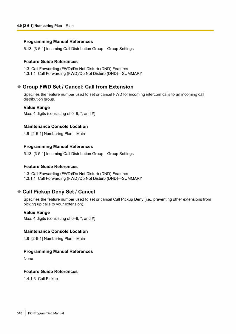
Programming Manual References5.13 [3-5-1] Incoming Call Distribution Group—Group Settings
Feature Guide References1.3 Call Forwarding (FWD)/Do Not Disturb (DND) Features1.3.1.1 Call Forwarding (FWD)/Do Not Disturb (DND)—SUMMARY
Group FWD Set / Cancel: Call from ExtensionSpecifies the feature number used to set or cancel FWD for incoming intercom calls to an incoming calldistribution group.
Value RangeMax. 4 digits (consisting of 0–9, *, and #)
Maintenance Console Location4.9 [2-6-1] Numbering Plan—Main
Programming Manual References5.13 [3-5-1] Incoming Call Distribution Group—Group Settings
Feature Guide References1.3 Call Forwarding (FWD)/Do Not Disturb (DND) Features1.3.1.1 Call Forwarding (FWD)/Do Not Disturb (DND)—SUMMARY
Call Pickup Deny Set / CancelSpecifies the feature number used to set or cancel Call Pickup Deny (i.e., preventing other extensions frompicking up calls to your extension).
Value RangeMax. 4 digits (consisting of 0–9, *, and #)
Maintenance Console Location4.9 [2-6-1] Numbering Plan—Main
Programming Manual ReferencesNone
Feature Guide References1.4.1.3 Call Pickup
510 PC Programming Manual
4.9 [2-6-1] Numbering Plan—Main

Paging Deny Set / CancelSpecifies the feature number used to set or cancel Paging Deny (i.e., preventing other extensions from pagingyour extension).
Value RangeMax. 4 digits (consisting of 0–9, *, and #)
Maintenance Console Location4.9 [2-6-1] Numbering Plan—Main
Programming Manual References5.10 [3-4] Paging Group
Feature Guide References1.16.1 Paging
Walking ExtensionSpecifies the feature number used to use the same extension settings at a new extension.
Value RangeMax. 4 digits (consisting of 0–9, *, and #)
Maintenance Console Location4.9 [2-6-1] Numbering Plan—Main
Programming Manual ReferencesNone
Feature Guide References1.28.3 Walking Extension Features
Data Line Security Set / CancelSpecifies the feature number used to set or cancel Data Line Security (i.e., preventing signals from otherextensions during data transmission).
Value RangeMax. 4 digits (consisting of 0–9, *, and #)
Maintenance Console Location4.9 [2-6-1] Numbering Plan—Main
PC Programming Manual 511
4.9 [2-6-1] Numbering Plan—Main

Programming Manual ReferencesNone
Feature Guide References1.11.5 Data Line Security
Manual Call Waiting for Extension CallSpecifies the feature number used to set or change the method of receiving a Call Waiting notification from anextension.
Value RangeMax. 4 digits (consisting of 0–9, *, and #)
Maintenance Console Location4.9 [2-6-1] Numbering Plan—Main
Programming Manual ReferencesNone
Feature Guide References1.1.3.3 Call Waiting
Automatic Call WaitingSpecifies the feature number used to set or cancel a Call Waiting notification from a trunk, doorphone, or acall via an incoming call distribution group.
Value RangeMax. 4 digits (consisting of 0–9, *, and #)
Maintenance Console Location4.9 [2-6-1] Numbering Plan—Main
Programming Manual ReferencesNone
Feature Guide References1.1.3.3 Call Waiting
Executive Override Deny Set / CancelSpecifies the feature number used to set or cancel Executive Busy Override (i.e., preventing other extensionsfrom joining your conversation).
512 PC Programming Manual
4.9 [2-6-1] Numbering Plan—Main
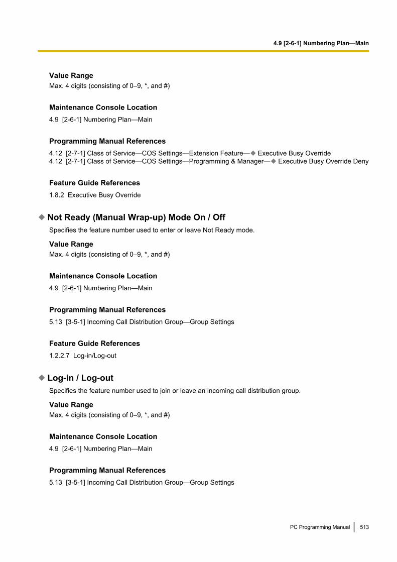
Value RangeMax. 4 digits (consisting of 0–9, *, and #)
Maintenance Console Location4.9 [2-6-1] Numbering Plan—Main
Programming Manual References4.12 [2-7-1] Class of Service—COS Settings—Extension Feature— Executive Busy Override4.12 [2-7-1] Class of Service—COS Settings—Programming & Manager— Executive Busy Override Deny
Feature Guide References1.8.2 Executive Busy Override
Not Ready (Manual Wrap-up) Mode On / OffSpecifies the feature number used to enter or leave Not Ready mode.
Value RangeMax. 4 digits (consisting of 0–9, *, and #)
Maintenance Console Location4.9 [2-6-1] Numbering Plan—Main
Programming Manual References5.13 [3-5-1] Incoming Call Distribution Group—Group Settings
Feature Guide References1.2.2.7 Log-in/Log-out
Log-in / Log-outSpecifies the feature number used to join or leave an incoming call distribution group.
Value RangeMax. 4 digits (consisting of 0–9, *, and #)
Maintenance Console Location4.9 [2-6-1] Numbering Plan—Main
Programming Manual References5.13 [3-5-1] Incoming Call Distribution Group—Group Settings
PC Programming Manual 513
4.9 [2-6-1] Numbering Plan—Main
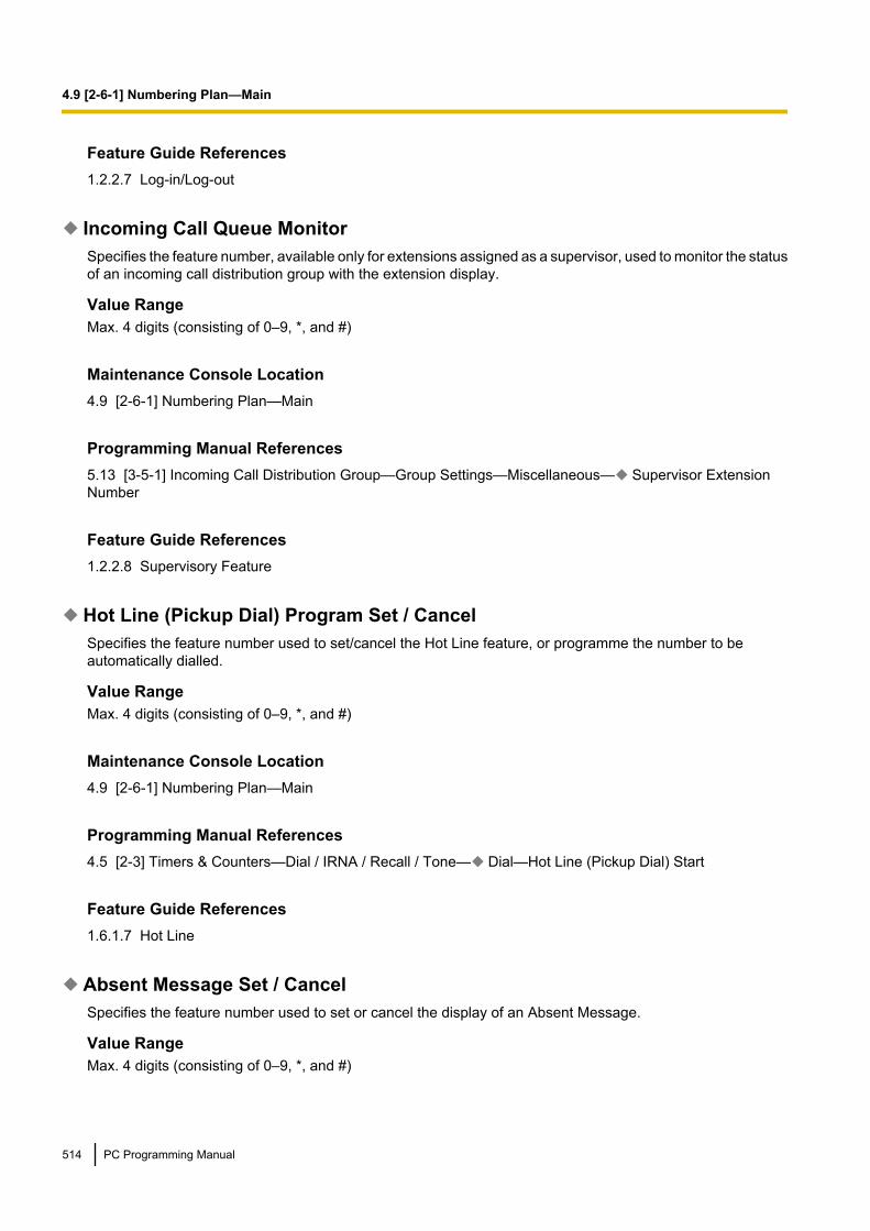
Feature Guide References1.2.2.7 Log-in/Log-out
Incoming Call Queue MonitorSpecifies the feature number, available only for extensions assigned as a supervisor, used to monitor the statusof an incoming call distribution group with the extension display.
Value RangeMax. 4 digits (consisting of 0–9, *, and #)
Maintenance Console Location4.9 [2-6-1] Numbering Plan—Main
Programming Manual References5.13 [3-5-1] Incoming Call Distribution Group—Group Settings—Miscellaneous— Supervisor ExtensionNumber
Feature Guide References1.2.2.8 Supervisory Feature
Hot Line (Pickup Dial) Program Set / CancelSpecifies the feature number used to set/cancel the Hot Line feature, or programme the number to beautomatically dialled.
Value RangeMax. 4 digits (consisting of 0–9, *, and #)
Maintenance Console Location4.9 [2-6-1] Numbering Plan—Main
Programming Manual References4.5 [2-3] Timers & Counters—Dial / IRNA / Recall / Tone— Dial—Hot Line (Pickup Dial) Start
Feature Guide References1.6.1.7 Hot Line
Absent Message Set / CancelSpecifies the feature number used to set or cancel the display of an Absent Message.
Value RangeMax. 4 digits (consisting of 0–9, *, and #)
514 PC Programming Manual
4.9 [2-6-1] Numbering Plan—Main

Maintenance Console Location4.9 [2-6-1] Numbering Plan—Main
Programming Manual ReferencesNone
Feature Guide References1.19.2 Absent Message
BGM Set / CancelSpecifies the feature number used to set or cancel the BGM heard through the telephone speaker whileon-hook.
Value RangeMax. 4 digits (consisting of 0–9, *, and #)
Maintenance Console Location4.9 [2-6-1] Numbering Plan—Main
Programming Manual References4.4 [2-2] Operator & BGM
Feature Guide References1.17.4 Background Music (BGM)
Remote Timed Reminder (Remote Wakeup Call)Specifies the feature number used to set or cancel a Timed Reminder remotely (Wake-up Call).
Value RangeMax. 4 digits (consisting of 0–9, *, and #)
Maintenance Console Location4.9 [2-6-1] Numbering Plan—Main
Programming Manual ReferencesNone
Feature Guide References1.28.4 Timed Reminder
PC Programming Manual 515
4.9 [2-6-1] Numbering Plan—Main

Timed Reminder Set / CancelSpecifies the feature number used to set or cancel a Timed Reminder.
Value RangeMax. 4 digits (consisting of 0–9, *, and #)
Maintenance Console Location4.9 [2-6-1] Numbering Plan—Main
Programming Manual ReferencesNone
Feature Guide References1.28.4 Timed Reminder
Printing MessageSpecifies the feature number used to select a Printing Message to be output on SMDR.
Value RangeMax. 4 digits (consisting of 0–9, *, and #)
Maintenance Console Location4.9 [2-6-1] Numbering Plan—Main
Programming Manual References8.2 [6-2] Hotel & Charge—Main— SMDR for External Hotel Application 2—Printing Message 1–8
Feature Guide References1.26.2 Printing Message
Extension Dial Lock Set / CancelSpecifies the feature number used to lock or unlock an extension to make certain trunk calls and change theforwarding destination, using the Extension Dial Lock feature.
Value RangeMax. 4 digits (consisting of 0–9, *, and #)
Maintenance Console Location4.9 [2-6-1] Numbering Plan—Main
516 PC Programming Manual
4.9 [2-6-1] Numbering Plan—Main

Programming Manual ReferencesNone
Feature Guide References1.9.3 Extension Dial Lock
Time Service (Day / Lunch / Break / Night) SwitchSpecifies the feature number, available for manager extensions, used to change the time mode manually.
Value RangeMax. 4 digits (consisting of 0–9, *, and #)
Maintenance Console Location4.9 [2-6-1] Numbering Plan—Main
Programming Manual References4.12 [2-7-1] Class of Service—COS Settings—Programming & Manager— Time Service Switch4.12 [2-7-1] Class of Service—COS Settings—Programming & Manager— Manager
Feature Guide References2.2.4 Time Service
Remote Extension Dial Lock OffSpecifies the feature number, available for manager extensions, used to unlock other extensions using theExtension Dial Lock feature.
Value RangeMax. 4 digits (consisting of 0–9, *, and #)
Maintenance Console Location4.9 [2-6-1] Numbering Plan—Main
Programming Manual References4.12 [2-7-1] Class of Service—COS Settings—Programming & Manager— Manager
Feature Guide References1.9.3 Extension Dial Lock
Remote Extension Dial Lock OnSpecifies the feature number, available for manager extensions, used to lock other extensions using theExtension Dial Lock feature.
PC Programming Manual 517
4.9 [2-6-1] Numbering Plan—Main

Value RangeMax. 4 digits (consisting of 0–9, *, and #)
Maintenance Console Location4.9 [2-6-1] Numbering Plan—Main
Programming Manual References4.12 [2-7-1] Class of Service—COS Settings—Programming & Manager— Manager
Feature Guide References1.9.3 Extension Dial Lock
Extension Feature ClearSpecifies the feature number used to reset certain features of an extension to the default values.
Value RangeMax. 4 digits (consisting of 0–9, *, and #)
Maintenance Console Location4.9 [2-6-1] Numbering Plan—Main
Programming Manual ReferencesNone
Feature Guide References1.28.2 Extension Feature Clear
Extension PIN Set / CancelSpecifies the feature number used to set a PIN for an extension.
Value RangeMax. 4 digits (consisting of 0–9, *, and #)
Maintenance Console Location4.9 [2-6-1] Numbering Plan—Main
Programming Manual ReferencesNone
518 PC Programming Manual
4.9 [2-6-1] Numbering Plan—Main

Feature Guide References1.28.1 Extension Personal Identification Number (PIN)
Dial Information (CTI)Specifies the feature number used to send dial information to the CTI feature instead of the PBX.
Value RangeMax. 4 digits (consisting of 0–9, *, and #)
Maintenance Console Location4.9 [2-6-1] Numbering Plan—Main
Programming Manual ReferencesNone
Feature Guide References1.32.1 Computer Telephony Integration (CTI)
Conference Group Call OperationSpecifies the feature number used to make a conference group call.
Value RangeMax. 4 digits (consisting of 0–9, *, and #)
Maintenance Console Location4.9 [2-6-1] Numbering Plan—Main
Programming Manual References4.5 [2-3] Timers & Counters—Miscellaneous— Conference Group Call—Ring Duration4.12 [2-7-1] Class of Service—COS Settings—Miscellaneous— Conference Group Call Operation5.27 [3-10] Conference Group
Feature Guide References1.15.1 Conference Group Call
Centralised BLF Monitor CancelSpecifies the feature number used to cancel monitoring of an extension using an NDSS button.
Value RangeMax. 4 digits (consisting of 0–9, *, and #)
PC Programming Manual 519
4.9 [2-6-1] Numbering Plan—Main
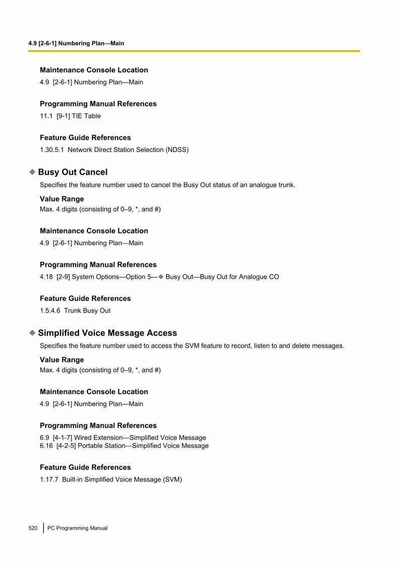
Maintenance Console Location4.9 [2-6-1] Numbering Plan—Main
Programming Manual References11.1 [9-1] TIE Table
Feature Guide References1.30.5.1 Network Direct Station Selection (NDSS)
Busy Out CancelSpecifies the feature number used to cancel the Busy Out status of an analogue trunk.
Value RangeMax. 4 digits (consisting of 0–9, *, and #)
Maintenance Console Location4.9 [2-6-1] Numbering Plan—Main
Programming Manual References4.18 [2-9] System Options—Option 5— Busy Out—Busy Out for Analogue CO
Feature Guide References1.5.4.6 Trunk Busy Out
Simplified Voice Message AccessSpecifies the feature number used to access the SVM feature to record, listen to and delete messages.
Value RangeMax. 4 digits (consisting of 0–9, *, and #)
Maintenance Console Location4.9 [2-6-1] Numbering Plan—Main
Programming Manual References6.9 [4-1-7] Wired Extension—Simplified Voice Message6.16 [4-2-5] Portable Station—Simplified Voice Message
Feature Guide References1.17.7 Built-in Simplified Voice Message (SVM)
520 PC Programming Manual
4.9 [2-6-1] Numbering Plan—Main

Other PBX ExtensionOther PBX extension numbers can be used to easily call extensions connected to PBXs at different locationsin a TIE line network. The leading numbers of all PBXs in the network that will be called should be entered inthis table. A maximum of 16 leading numbers can be programmed.
DialSpecifies the leading extension number of the other PBX.
Value RangeMax. 3 digits (consisting of 0–9, *, and #)
Maintenance Console Location4.9 [2-6-1] Numbering Plan—Main
Programming Manual References11.1 [9-1] TIE Table— Leading Number
Feature Guide References1.30.1 TIE Line Service
KX-T7710The settings of the MESSAGE button and One-touch buttons on the KX-T7710 can be programmed.
DialIndicates the DTMF tone dial required by the PBX to recognise it and dial the preprogrammed number for eachbutton (reference only).
Value RangeB: For MESSAGE buttonA1: For One-touch button 1A2: For One-touch button 2A3: For One-touch button 3A4: For One-touch button 4A5: For One-touch button 5A6: For One-touch button 6A7: For One-touch button 7A8: For One-touch button 8
Maintenance Console Location4.9 [2-6-1] Numbering Plan—Main
Programming Manual ReferencesNone
PC Programming Manual 521
4.9 [2-6-1] Numbering Plan—Main
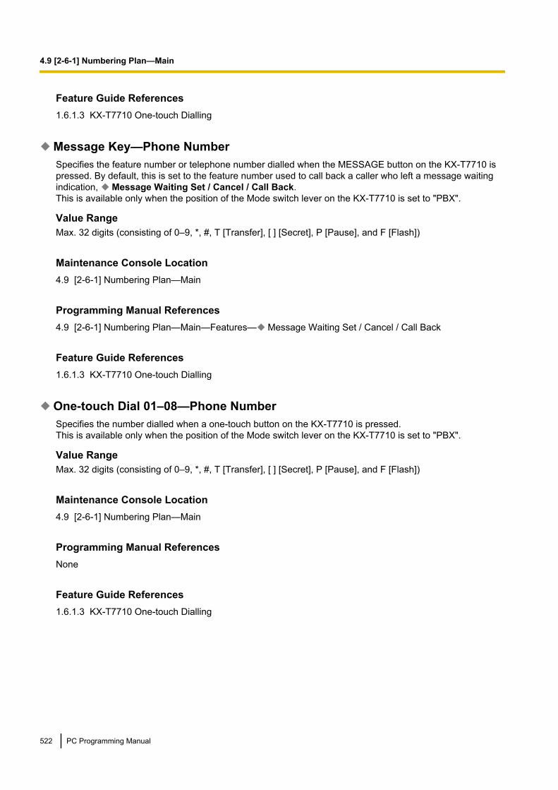
Feature Guide References1.6.1.3 KX-T7710 One-touch Dialling
Message Key—Phone NumberSpecifies the feature number or telephone number dialled when the MESSAGE button on the KX-T7710 ispressed. By default, this is set to the feature number used to call back a caller who left a message waitingindication, Message Waiting Set / Cancel / Call Back.This is available only when the position of the Mode switch lever on the KX-T7710 is set to "PBX".
Value RangeMax. 32 digits (consisting of 0–9, *, #, T [Transfer], [ ] [Secret], P [Pause], and F [Flash])
Maintenance Console Location4.9 [2-6-1] Numbering Plan—Main
Programming Manual References4.9 [2-6-1] Numbering Plan—Main—Features— Message Waiting Set / Cancel / Call Back
Feature Guide References1.6.1.3 KX-T7710 One-touch Dialling
One-touch Dial 01–08—Phone NumberSpecifies the number dialled when a one-touch button on the KX-T7710 is pressed.This is available only when the position of the Mode switch lever on the KX-T7710 is set to "PBX".
Value RangeMax. 32 digits (consisting of 0–9, *, #, T [Transfer], [ ] [Secret], P [Pause], and F [Flash])
Maintenance Console Location4.9 [2-6-1] Numbering Plan—Main
Programming Manual ReferencesNone
Feature Guide References1.6.1.3 KX-T7710 One-touch Dialling
522 PC Programming Manual
4.9 [2-6-1] Numbering Plan—Main

4.10 [2-6-2] Numbering Plan—Quick DialQuick Dialling numbers are used to call extensions or outside parties, or access certain features without havingto dial their full numbers. It is possible to register Quick Dialling numbers that overlap with other registerednumbers (refer to "Automatic Rerouting of VoIP Calls to Public Trunks" in the Feature Guide).A maximum of 80 Quick Dialling numbers can be programmed in Basic Memory, and a maximum of 4000Quick Dialling numbers can be programmed in Expansion. To display other sets of numbers, click theapplicable tab.For more information on flexible numbering, see "2.3.6 Flexible Numbering/Fixed Numbering" in the FeatureGuide.
Use quick dial for rerouting to public CO when TIE line does not workSpecifies whether to check if the quick dial numbering plan is compatible (does not overlap) with the mainnumbering plan.
Value RangeDisable: Checks whether the quick dial numbering plan is compatible with the main numbering plan.Enable: Does not check whether the quick dial numbering plan is compatible with the main numbering plan.
Maintenance Console Location4.10 [2-6-2] Numbering Plan—Quick Dial
Programming Manual ReferencesNone
Feature Guide References1.6.1.6 Quick Dialling1.30.2 Voice over Internet Protocol (VoIP) Network2.3.6 Flexible Numbering/Fixed Numbering
DialSpecifies the Quick Dialling number.
Value RangeBasic Memory: Max. 4 digits (consisting of 0–9, *, and #)Expand 1–4000: Max. 8 digits (consisting of 0–9, *, and #)
Maintenance Console Location4.10 [2-6-2] Numbering Plan—Quick Dial
Programming Manual ReferencesNone
PC Programming Manual 523
4.10 [2-6-2] Numbering Plan—Quick Dial
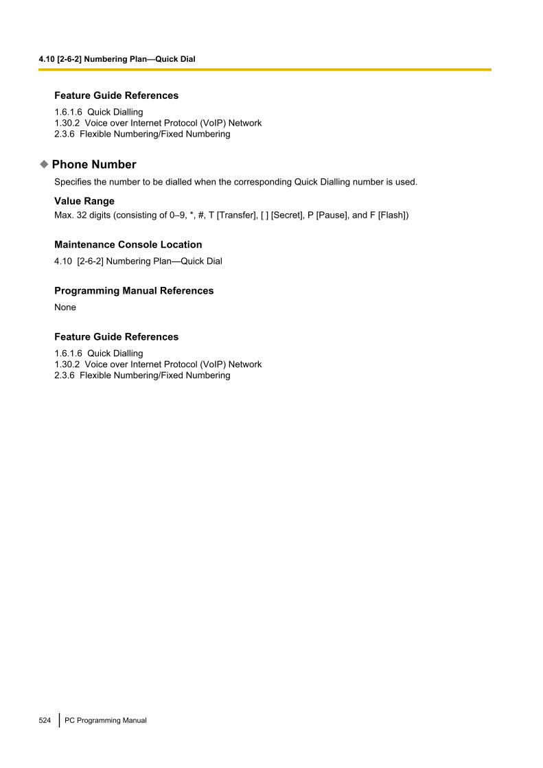
Feature Guide References1.6.1.6 Quick Dialling1.30.2 Voice over Internet Protocol (VoIP) Network2.3.6 Flexible Numbering/Fixed Numbering
Phone NumberSpecifies the number to be dialled when the corresponding Quick Dialling number is used.
Value RangeMax. 32 digits (consisting of 0–9, *, #, T [Transfer], [ ] [Secret], P [Pause], and F [Flash])
Maintenance Console Location4.10 [2-6-2] Numbering Plan—Quick Dial
Programming Manual ReferencesNone
Feature Guide References1.6.1.6 Quick Dialling1.30.2 Voice over Internet Protocol (VoIP) Network2.3.6 Flexible Numbering/Fixed Numbering
524 PC Programming Manual
4.10 [2-6-2] Numbering Plan—Quick Dial

4.11 [2-6-3] Numbering Plan—B/NA DND Call FeatureFeature numbers used to access various PBX features can be programmed. The following features areavailable while hearing a busy, DND, or ringback tone. Each feature must have a unique feature number.For more information on flexible numbering, see "2.3.6 Flexible Numbering/Fixed Numbering" in the FeatureGuide.
BSS / OHCA / Whisper OHCA / DND OverrideSpecifies the feature number used to notify a busy extension of a second call by Call Waiting, or call anextension in DND mode.
Value Range1 digit (0–9, *, or #)
Maintenance Console Location4.11 [2-6-3] Numbering Plan—B/NA DND Call Feature
Programming Manual References6.1 [4-1-1] Wired Extension—Extension Settings—Option 2— Manual C. Waiting for Extension Call6.10 [4-2-1] Portable Station—Extension Settings—Option 2— Manual C. Waiting for Extension Call
Feature Guide References1.1.3.3 Call Waiting1.3.1.3 Do Not Disturb (DND)1.8.4.2 Call Waiting Tone1.8.4.3 Off-hook Call Announcement (OHCA)1.8.4.4 Whisper OHCA
Executive Busy OverrideSpecifies the feature number used to interrupt an existing call to establish a three-party conference call.
Value Range1 digit (0–9, *, or #)
Maintenance Console Location4.11 [2-6-3] Numbering Plan—B/NA DND Call Feature
Programming Manual References4.12 [2-7-1] Class of Service—COS Settings—Extension Feature— Executive Busy Override6.1 [4-1-1] Wired Extension—Extension Settings—Option 3— Executive Override Deny6.10 [4-2-1] Portable Station—Extension Settings—Option 3— Executive Override Deny
Feature Guide References1.8.2 Executive Busy Override
PC Programming Manual 525
4.11 [2-6-3] Numbering Plan—B/NA DND Call Feature

Alternate Calling - Ring / VoiceSpecifies the feature number used to allow a caller to change the called extension’s preset call receivingmethod to ring tone or voice.
Value Range1 digit (0–9, *, or #)
Maintenance Console Location4.11 [2-6-3] Numbering Plan—B/NA DND Call Feature
Programming Manual ReferencesNone
Feature Guide References1.5.3 Intercom Call
Message Waiting SetSpecifies the feature number used to leave a Message Waiting notification.
Value Range1 digit (0–9, *, or #)
Maintenance Console Location4.11 [2-6-3] Numbering Plan—B/NA DND Call Feature
Programming Manual ReferencesNone
Feature Guide References1.19.1 Message Waiting
Call MonitorSpecifies the feature number used to listen to a busy extension’s conversation.
Value Range1 digit (0–9, *, or #)
Maintenance Console Location4.11 [2-6-3] Numbering Plan—B/NA DND Call Feature
526 PC Programming Manual
4.11 [2-6-3] Numbering Plan—B/NA DND Call Feature
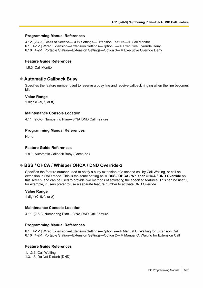
Programming Manual References4.12 [2-7-1] Class of Service—COS Settings—Extension Feature— Call Monitor6.1 [4-1-1] Wired Extension—Extension Settings—Option 3— Executive Override Deny6.10 [4-2-1] Portable Station—Extension Settings—Option 3— Executive Override Deny
Feature Guide References1.8.3 Call Monitor
Automatic Callback BusySpecifies the feature number used to reserve a busy line and receive callback ringing when the line becomesidle.
Value Range1 digit (0–9, *, or #)
Maintenance Console Location4.11 [2-6-3] Numbering Plan—B/NA DND Call Feature
Programming Manual ReferencesNone
Feature Guide References1.8.1 Automatic Callback Busy (Camp-on)
BSS / OHCA / Whisper OHCA / DND Override-2Specifies the feature number used to notify a busy extension of a second call by Call Waiting, or call anextension in DND mode. This is the same setting as BSS / OHCA / Whisper OHCA / DND Override onthis screen, and can be used to provide two methods of activating the specified features. This can be useful,for example, if users prefer to use a separate feature number to activate DND Override.
Value Range1 digit (0–9, *, or #)
Maintenance Console Location4.11 [2-6-3] Numbering Plan—B/NA DND Call Feature
Programming Manual References6.1 [4-1-1] Wired Extension—Extension Settings—Option 2— Manual C. Waiting for Extension Call6.10 [4-2-1] Portable Station—Extension Settings—Option 2— Manual C. Waiting for Extension Call
Feature Guide References1.1.3.3 Call Waiting1.3.1.3 Do Not Disturb (DND)
PC Programming Manual 527
4.11 [2-6-3] Numbering Plan—B/NA DND Call Feature

1.8.4.2 Call Waiting Tone1.8.4.3 Off-hook Call Announcement (OHCA)1.8.4.4 Whisper OHCA
528 PC Programming Manual
4.11 [2-6-3] Numbering Plan—B/NA DND Call Feature

4.12 [2-7-1] Class of Service—COS SettingsEach extension, doorphone port, incoming call distribution group, and trunk group is assigned a Class ofService (COS). Certain features can be programmed to behave differently depending on the COS. A maximumof 64 COS levels can be programmed.
TRSRestrictions to features related to making trunk calls can be programmed for each COS.
COS NameSpecifies the name of the COS.
Value RangeMax. 20 characters
Maintenance Console Location4.12 [2-7-1] Class of Service—COS Settings
Programming Manual ReferencesNone
Feature Guide References2.2.1 Class of Service (COS)
TRS Level—Day, Lunch, Break, NightSpecifies the Toll Restriction (TRS)/Call Barring (Barring) level for making trunk calls in each time mode.
Value Range1: Allows all trunk calls2–6: Restricts trunk calls according to the combination of the Denied and Exception Code Tables7: Restricts all trunk calls
Maintenance Console Location4.12 [2-7-1] Class of Service—COS Settings
Programming Manual References4.6 [2-4] Week Table5.1 [3-1-1] Trunk Group—TRG Settings—Main— COS5.13 [3-5-1] Incoming Call Distribution Group—Group Settings—Main— COS6.1 [4-1-1] Wired Extension—Extension Settings—Main— COS6.10 [4-2-1] Portable Station—Extension Settings—Main— COS7.1 [5-1] Doorphone— COS9.1 [7-1] Denied Code9.2 [7-2] Exception Code
PC Programming Manual 529
4.12 [2-7-1] Class of Service—COS Settings

Feature Guide References1.9.1 Toll Restriction (TRS)/Call Barring (Barring)
TRS Level on Extension LockSpecifies the TRS/Barring level for making trunk calls when an extension is locked using the Extension DialLock feature.
Value Range1: Allows all trunk calls2–6: Restricts trunk calls according to the combination of the Denied and Exception Code Tables7: Restricts all trunk calls
Maintenance Console Location4.12 [2-7-1] Class of Service—COS Settings
Programming Manual References6.1 [4-1-1] Wired Extension—Extension Settings—Main— COS6.10 [4-2-1] Portable Station—Extension Settings—Main— COS9.1 [7-1] Denied Code9.2 [7-2] Exception Code
Feature Guide References1.9.3 Extension Dial Lock
TRS Level for System Speed DiallingSpecifies the TRS/Barring level for making a trunk call using System Speed Dialling numbers, which overridesthe TRS/Barring set for the current time mode.
Value Range1: Allows all trunk calls2–6: Restricts trunk calls according to the combination of the Denied and Exception Code Tables7: Restricts all trunk calls
Maintenance Console Location4.12 [2-7-1] Class of Service—COS Settings
Programming Manual References6.1 [4-1-1] Wired Extension—Extension Settings—Main— COS6.10 [4-2-1] Portable Station—Extension Settings—Main— COS8.1 [6-1] System Speed Dial9.5 [7-5] Miscellaneous— TRS Override by System Speed Dialling
Feature Guide References1.6.1.5 Speed Dialling—Personal/System
530 PC Programming Manual
4.12 [2-7-1] Class of Service—COS Settings

1.9.1 Toll Restriction (TRS)/Call Barring (Barring)
CO & SMDRCOS NameSpecifies the name of the COS.
Value RangeMax. 20 characters
Maintenance Console Location4.12 [2-7-1] Class of Service—COS Settings
Programming Manual ReferencesNone
Feature Guide References2.2.1 Class of Service (COS)
Extension-CO Line Call Duration LimitEnables the extension-to-trunk call duration feature. The maximum call duration can be set using Extension-CO Duration Time (*60s) on 5.1 [3-1-1] Trunk Group—TRG Settings.
Value RangeDisable, Enable
Maintenance Console Location4.12 [2-7-1] Class of Service—COS Settings
Programming Manual References4.18 [2-9] System Options—Option 2— Extension - CO Call Limitation—For Incoming Call5.1 [3-1-1] Trunk Group—TRG Settings—Main— COS6.1 [4-1-1] Wired Extension—Extension Settings—Main— COS6.10 [4-2-1] Portable Station—Extension Settings—Main— COS
Feature Guide References1.11.8 Trunk Call Limitation
Transfer to COEnables the transferring of calls to trunks.
Value RangeDisable, Enable
PC Programming Manual 531
4.12 [2-7-1] Class of Service—COS Settings

Maintenance Console Location4.12 [2-7-1] Class of Service—COS Settings
Programming Manual References6.1 [4-1-1] Wired Extension—Extension Settings—Main— COS6.10 [4-2-1] Portable Station—Extension Settings—Main— COS
Feature Guide References1.12.1 Call Transfer
Call Forward to COEnables the forwarding of calls to trunks.
Value RangeDisable, Enable
Maintenance Console Location4.12 [2-7-1] Class of Service—COS Settings
Programming Manual References6.1 [4-1-1] Wired Extension—Extension Settings—Main— COS6.3 [4-1-2] Wired Extension—FWD/DND6.10 [4-2-1] Portable Station—Extension Settings—Main— COS6.12 [4-2-2] Portable Station—FWD/DND
Feature Guide References1.3.1.2 Call Forwarding (FWD)
Account Code ModeSpecifies whether the entry of an account code is optional or mandatory when making a trunk call.
Value RangeOption, Forced
Maintenance Console Location4.12 [2-7-1] Class of Service—COS Settings
Programming Manual References6.1 [4-1-1] Wired Extension—Extension Settings—Main— COS6.10 [4-2-1] Portable Station—Extension Settings—Main— COS
532 PC Programming Manual
4.12 [2-7-1] Class of Service—COS Settings

Feature Guide References1.5.4.3 Account Code Entry
CF (MSN)Enables forwarding of ISDN calls to an outside party using the ISDN service of the telephone company, insteadof the PBX, on an MSN basis.
Value RangeDisable, Enable
Maintenance Console Location4.12 [2-7-1] Class of Service—COS Settings
Programming Manual ReferencesNone
Feature Guide References1.21.1.4 Call Forwarding (CF)—by ISDN (P-MP)1.21.1.5 Call Forwarding (CF)—by ISDN (P-P)
Outgoing CO Call Printout (SMDR)Enables the automatic recording of information about outgoing trunk calls on SMDR.
Value RangeDisable, Enable
Maintenance Console Location4.12 [2-7-1] Class of Service—COS Settings
Programming Manual References6.1 [4-1-1] Wired Extension—Extension Settings—Main— COS6.10 [4-2-1] Portable Station—Extension Settings—Main— COS13.1 [11-1] Main
Feature Guide References1.26.1.1 Station Message Detail Recording (SMDR)
Extension FeatureThe use of features related to extension operations can be programmed for each COS.
PC Programming Manual 533
4.12 [2-7-1] Class of Service—COS Settings

COS NameSpecifies the name of the COS.
Value RangeMax. 20 characters
Maintenance Console Location4.12 [2-7-1] Class of Service—COS Settings
Programming Manual ReferencesNone
Feature Guide References2.2.1 Class of Service (COS)
Executive Busy OverrideEnables interrupting an existing call to establish a three-party conference call.
Value RangeDisable, Enable
Maintenance Console Location4.12 [2-7-1] Class of Service—COS Settings
Programming Manual References6.1 [4-1-1] Wired Extension—Extension Settings—Main— COS6.10 [4-2-1] Portable Station—Extension Settings—Main— COS
Feature Guide References1.8.2 Executive Busy Override
DND OverrideEnables making a call to an extension in DND mode by entering the feature number.
Value RangeDisable, Enable
Maintenance Console Location4.12 [2-7-1] Class of Service—COS Settings
534 PC Programming Manual
4.12 [2-7-1] Class of Service—COS Settings

Programming Manual References6.1 [4-1-1] Wired Extension—Extension Settings—Main— COS6.3 [4-1-2] Wired Extension—FWD/DND6.10 [4-2-1] Portable Station—Extension Settings—Main— COS6.12 [4-2-2] Portable Station—FWD/DND
Feature Guide References1.3.1.3 Do Not Disturb (DND)
OHCA / Whisper OHCAEnables using OHCA/Whisper OHCA as a method of second call notification by entering the feature number.
Value RangeDisable, Enable
Maintenance Console Location4.12 [2-7-1] Class of Service—COS Settings
Programming Manual References6.1 [4-1-1] Wired Extension—Extension Settings—Main— COS6.10 [4-2-1] Portable Station—Extension Settings—Main— COS
Feature Guide References1.8.4 Second Call Notification to Busy Extension1.8.4.3 Off-hook Call Announcement (OHCA)1.8.4.4 Whisper OHCA
Call MonitorEnables listening to a busy extension’s conversation.
Value RangeDisable, Enable
Maintenance Console Location4.12 [2-7-1] Class of Service—COS Settings
Programming Manual References6.1 [4-1-1] Wired Extension—Extension Settings—Main— COS6.10 [4-2-1] Portable Station—Extension Settings—Main— COS
Feature Guide References1.8.3 Call Monitor
PC Programming Manual 535
4.12 [2-7-1] Class of Service—COS Settings

Call Pickup by DSSEnables using a DSS button to pick up a call to a specified extension.
Value RangeDisable, Enable
Maintenance Console Location4.12 [2-7-1] Class of Service—COS Settings
Programming Manual References6.1 [4-1-1] Wired Extension—Extension Settings—Main— COS6.5 [4-1-4] Wired Extension—Flexible Button6.10 [4-2-1] Portable Station—Extension Settings—Main— COS6.13 [4-2-3] Portable Station—Flexible Button6.17 [4-3] DSS Console
Feature Guide References1.4.1.3 Call Pickup
Programming & ManagerCOS NameSpecifies the name of the COS.
Value RangeMax. 20 characters
Maintenance Console Location4.12 [2-7-1] Class of Service—COS Settings
Programming Manual ReferencesNone
Feature Guide References2.2.1 Class of Service (COS)
Executive Busy Override DenyEnables preventing other extensions from interrupting calls.
Value RangeDisable, Enable
536 PC Programming Manual
4.12 [2-7-1] Class of Service—COS Settings

Maintenance Console Location4.12 [2-7-1] Class of Service—COS Settings
Programming Manual References6.1 [4-1-1] Wired Extension—Extension Settings—Main— COS6.10 [4-2-1] Portable Station—Extension Settings—Main— COS
Feature Guide References2.2.1 Class of Service (COS)
Group Forward SetEnables setting call forwarding for calls to an incoming call distribution group.
Value RangeDisable: An extension cannot set call forwarding for any group.Enable-All: An extension can set call forwarding for all groups.Enable-Group: An extension can only set call forwarding for the group to which the extension belongs.
Maintenance Console Location4.12 [2-7-1] Class of Service—COS Settings
Programming Manual References5.14 [3-5-1] Incoming Call Distribution Group—Group Settings—Member List6.1 [4-1-1] Wired Extension—Extension Settings—Main— COS6.10 [4-2-1] Portable Station—Extension Settings—Main— COS
Feature Guide References1.3.1.2 Call Forwarding (FWD)
Programming Mode LevelSpecifies the level of authorisation for performing PT programming.
Value RangeDisable: A PT user cannot perform any programming.PROG Only: A PT user can perform only personal programming.PROG and PROG **/*#: A PT user can perform both personal and system programming.
Maintenance Console Location4.12 [2-7-1] Class of Service—COS Settings
Programming Manual References6.1 [4-1-1] Wired Extension—Extension Settings—Main— COS6.10 [4-2-1] Portable Station—Extension Settings—Main— COS
PC Programming Manual 537
4.12 [2-7-1] Class of Service—COS Settings

Feature Guide References2.3.2 PT Programming
ManagerSpecifies the authorisation to use manager features.
Value RangeDisable, Enable
Maintenance Console Location4.12 [2-7-1] Class of Service—COS Settings
Programming Manual References6.1 [4-1-1] Wired Extension—Extension Settings—Main— COS6.10 [4-2-1] Portable Station—Extension Settings—Main— COS
Feature Guide References2.2.6 Manager Features
Time Service SwitchEnables manual switching of time modes.
Value RangeDisable, Enable
Maintenance Console Location4.12 [2-7-1] Class of Service—COS Settings
Programming Manual References4.6 [2-4] Week Table6.1 [4-1-1] Wired Extension—Extension Settings—Main— COS6.10 [4-2-1] Portable Station—Extension Settings—Main— COS
Feature Guide References2.2.4 Time Service
PDN/SDNAn SDN button allows a PT user to see the current status of the corresponding PDN extension, and to pick upor transfer calls to that extension easily. The settings here control how SDN buttons operate for extensions ateach COS level.
538 PC Programming Manual
4.12 [2-7-1] Class of Service—COS Settings
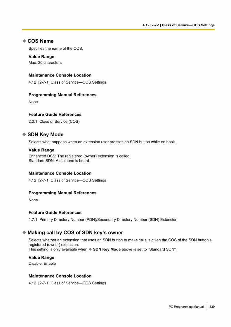
COS NameSpecifies the name of the COS.
Value RangeMax. 20 characters
Maintenance Console Location4.12 [2-7-1] Class of Service—COS Settings
Programming Manual ReferencesNone
Feature Guide References2.2.1 Class of Service (COS)
SDN Key ModeSelects what happens when an extension user presses an SDN button while on hook.
Value RangeEnhanced DSS: The registered (owner) extension is called.Standard SDN: A dial tone is heard.
Maintenance Console Location4.12 [2-7-1] Class of Service—COS Settings
Programming Manual ReferencesNone
Feature Guide References1.7.1 Primary Directory Number (PDN)/Secondary Directory Number (SDN) Extension
Making call by COS of SDN key’s ownerSelects whether an extension that uses an SDN button to make calls is given the COS of the SDN button’sregistered (owner) extension.This setting is only available when SDN Key Mode above is set to "Standard SDN".
Value RangeDisable, Enable
Maintenance Console Location4.12 [2-7-1] Class of Service—COS Settings
PC Programming Manual 539
4.12 [2-7-1] Class of Service—COS Settings

Programming Manual References4.12 [2-7-1] Class of Service—COS Settings—PDN/SDN— COS Name
Feature Guide References1.7.1 Primary Directory Number (PDN)/Secondary Directory Number (SDN) Extension
SDN Key Assignment by PT ProgramSelects whether PT users can create SDN buttons on their own extensions using PT programming.
Value RangeDisable, Enable
Maintenance Console Location4.12 [2-7-1] Class of Service—COS Settings
Programming Manual ReferencesNone
Feature Guide References1.7.1 Primary Directory Number (PDN)/Secondary Directory Number (SDN) Extension
Optional Device & Other ExtensionsCOS NameSpecifies the name of the COS.
Value RangeMax. 20 characters
Maintenance Console Location4.12 [2-7-1] Class of Service—COS Settings
Programming Manual ReferencesNone
Feature Guide References2.2.1 Class of Service (COS)
Door UnlockEnables using the door opener feature.
540 PC Programming Manual
4.12 [2-7-1] Class of Service—COS Settings

Value RangeDisable, Enable
Maintenance Console Location4.12 [2-7-1] Class of Service—COS Settings
Programming Manual References6.1 [4-1-1] Wired Extension—Extension Settings—Main— COS6.10 [4-2-1] Portable Station—Extension Settings—Main— COS
Feature Guide References1.17.2 Door Open
External Relay AccessEnables access to external relays.
Value RangeDisable, Enable
Maintenance Console Location4.12 [2-7-1] Class of Service—COS Settings
Programming Manual References7.6 [5-4] External Relay
Feature Guide References1.17.9 External Relay Control
Accept the Call from DISAEnables reception of calls from DISA.
Value RangeDisable, Enable
Maintenance Console Location4.12 [2-7-1] Class of Service—COS Settings
Programming Manual References6.1 [4-1-1] Wired Extension—Extension Settings—Main— COS6.10 [4-2-1] Portable Station—Extension Settings—Main— COS7.4 [5-3-2] Voice Message—DISA Message
PC Programming Manual 541
4.12 [2-7-1] Class of Service—COS Settings

Feature Guide References1.17.6 Direct Inward System Access (DISA)
Remote Operation by Other ExtensionAllows the Walking COS feature to be used from a remote location (inside the PBX, or outside the PBX usingDISA).
Value RangeAllow, Deny
Maintenance Console Location4.12 [2-7-1] Class of Service—COS Settings
Programming Manual References6.1 [4-1-1] Wired Extension—Extension Settings—Main— COS6.10 [4-2-1] Portable Station—Extension Settings—Main— COS
Feature Guide References1.9.5 Walking COS
Accept Wireless XDP Parallel Mode Set by PSAllows Wireless XDP Parallel Mode to be set by a PS.
Value RangeAllow, Deny
Maintenance Console Location4.12 [2-7-1] Class of Service—COS Settings
Programming Manual References6.1 [4-1-1] Wired Extension—Extension Settings—Main— COS
Feature Guide References1.25.5 Wireless XDP Parallel Mode
MiscellaneousCOS NameSpecifies the name of the COS.
Value RangeMax. 20 characters
542 PC Programming Manual
4.12 [2-7-1] Class of Service—COS Settings
Maintenance Console Location4.12 [2-7-1] Class of Service—COS Settings
Programming Manual ReferencesNone
Feature Guide References2.2.1 Class of Service (COS)
Conference Group Call OperationEnables making conference group calls.
Value RangeDisable, Enable
Maintenance Console Location4.12 [2-7-1] Class of Service—COS Settings
Programming Manual References4.5 [2-3] Timers & Counters—Miscellaneous— Conference Group Call—Ring Duration4.9 [2-6-1] Numbering Plan—Main—Features— Conference Group Call Operation5.27 [3-10] Conference Group
Feature Guide References1.15.1 Conference Group Call
Accept a collect call (for Brazil)Enables accepting collect calls.
Value RangeDisable, Enable
Maintenance Console Location4.12 [2-7-1] Class of Service—COS Settings
Programming Manual ReferencesNone
Feature Guide ReferencesNone
PC Programming Manual 543
4.12 [2-7-1] Class of Service—COS Settings

4.13 [2-7-2] Class of Service—External Call BlockEach COS can have different trunk groups available for making trunk calls, depending on the time mode (day/lunch/break/night). Select the desired time mode from the list.
Outgoing Trunk Group 1–64 (KX-TDE100/KX-TDE200) or 1–96 (KX-TDE600)Specifies the available trunk groups.
Value RangeBlock (blue), Non Block
Maintenance Console Location4.13 [2-7-2] Class of Service—External Call Block
Programming Manual References4.6 [2-4] Week Table6.1 [4-1-1] Wired Extension—Extension Settings6.10 [4-2-1] Portable Station—Extension Settings12.1 [10-1] CO Line Settings
Feature Guide References1.5.5.3 Trunk Access
544 PC Programming Manual
4.13 [2-7-2] Class of Service—External Call Block

4.14 [2-7-3] Class of Service—Internal Call BlockInternal Call Block determines the restrictions placed on making intercom calls. The extensions, incoming calldistribution groups, and doorphones belonging to a certain COS can be programmed to not receive intercomcalls from those belonging to a certain COS.
COS Number of the Extension Which Receive the Call from Other Extension 1–64
Specifies the combinations of COS levels for which intercom calls are blocked.
Value RangeBlock (blue), Non Block
Maintenance Console Location4.14 [2-7-3] Class of Service—Internal Call Block
Programming Manual References5.13 [3-5-1] Incoming Call Distribution Group—Group Settings—Main— COS6.1 [4-1-1] Wired Extension—Extension Settings—Main— COS6.10 [4-2-1] Portable Station—Extension Settings—Main— COS7.1 [5-1] Doorphone— COS
Feature Guide References1.1.2.2 Internal Call Block
PC Programming Manual 545
4.14 [2-7-3] Class of Service—Internal Call Block

4.15 [2-8-1] Ring Tone Patterns—Call from CODifferent ring tone patterns can be selected for incoming trunk calls depending on the trunk group that the callsare received on. A maximum of 8 Ring Tone Pattern Tables can be programmed, and any pattern table canbe selected for use by an extension.
Ring Tone Pattern Plan 1–8Specifies the ring tone pattern for incoming trunk calls.
Value RangeSingle, Double, Triple, Option1, Option2
Maintenance Console Location4.15 [2-8-1] Ring Tone Patterns—Call from CO
Programming Manual References12.1 [10-1] CO Line Settings— Trunk Group Number6.1 [4-1-1] Wired Extension—Extension Settings—Option 1— Ring Pattern Table6.10 [4-2-1] Portable Station—Extension Settings—Option 1— Ring Pattern Table
Feature Guide References1.1.3.2 Ring Tone Pattern Selection
546 PC Programming Manual
4.15 [2-8-1] Ring Tone Patterns—Call from CO

4.16 [2-8-2] Ring Tone Patterns—Call fromDoorphone
Different ring tone patterns can be selected for incoming doorphone calls depending on the doorphone portthat the calls originate from. A maximum of 8 Ring Tone Pattern Tables can be programmed, and any patterntable can be selected for use by an extension.
Ring Tone Pattern Plan 1–8Specifies the ring tone pattern for incoming doorphone calls.
Value RangeSingle, Double, Triple, S-Double, Option 1, Option 2
Maintenance Console Location4.16 [2-8-2] Ring Tone Patterns—Call from Doorphone
Programming Manual References6.1 [4-1-1] Wired Extension—Extension Settings—Option 1— Ring Pattern Table6.10 [4-2-1] Portable Station—Extension Settings—Option 1— Ring Pattern Table7.1 [5-1] Doorphone
Feature Guide References1.1.3.2 Ring Tone Pattern Selection1.17.1 Doorphone Call
PC Programming Manual 547
4.16 [2-8-2] Ring Tone Patterns—Call from Doorphone

4.17 [2-8-3] Ring Tone Patterns—Call from OthersDifferent ring tone patterns can be selected for incoming intercom calls and ringing triggered by certain PBXfeatures (Timed Reminder, Call Back, and Live Call Screening). A maximum of 8 Ring Tone Pattern Tablescan be programmed, and any pattern table can be selected for use by an extension.For more information on ring tone patterns, see "1.1.3.2 Ring Tone Pattern Selection" in the Feature Guide.
Extension—Ring Tone Pattern Plan 1–8Specifies the ring tone pattern for incoming intercom calls.
Value RangeSingle, Double, Triple, Option 1, Option 2
Maintenance Console Location4.17 [2-8-3] Ring Tone Patterns—Call from Others
Programming Manual References6.1 [4-1-1] Wired Extension—Extension Settings—Option 1— Ring Pattern Table6.10 [4-2-1] Portable Station—Extension Settings—Option 1— Ring Pattern Table
Feature Guide ReferencesNone
Timed Reminder—Ring Tone Pattern Plan 1–8Specifies the ring tone pattern for Timed Reminder alarms.
Value RangeSingle, Double, Triple, Option 1, Option 2
Maintenance Console Location4.17 [2-8-3] Ring Tone Patterns—Call from Others
Programming Manual References6.1 [4-1-1] Wired Extension—Extension Settings—Option 1— Ring Pattern Table6.10 [4-2-1] Portable Station—Extension Settings—Option 1— Ring Pattern Table
Feature Guide ReferencesNone
Call Back—Ring Tone Pattern Plan 1–8Specifies the ring tone pattern for callback ringing by Automatic Callback Busy.
548 PC Programming Manual
4.17 [2-8-3] Ring Tone Patterns—Call from Others
Value RangeSingle, Double, Triple, S-Double, Option 1, Option 2
Maintenance Console Location4.17 [2-8-3] Ring Tone Patterns—Call from Others
Programming Manual References6.1 [4-1-1] Wired Extension—Extension Settings—Option 1— Ring Pattern Table6.10 [4-2-1] Portable Station—Extension Settings—Option 1— Ring Pattern Table
Feature Guide ReferencesNone
Live Call Screening—Ring Tone Pattern Plan 1–8Specifies the ring tone pattern for LCS warning tones.
Value RangeSingle, Double, Triple, Option 1, Option 2
Maintenance Console Location4.17 [2-8-3] Ring Tone Patterns—Call from Others
Programming Manual References6.1 [4-1-1] Wired Extension—Extension Settings—Option 1— Ring Pattern Table6.10 [4-2-1] Portable Station—Extension Settings—Option 1— Ring Pattern Table
Feature Guide ReferencesNone
External Sensor—Ring Tone Pattern Plan 1–8Specifies the ring tone pattern for calls from an external sensor.
Value RangeSingle, Double, Triple, Option 1, Option 2
Maintenance Console Location4.17 [2-8-3] Ring Tone Patterns—Call from Others
Programming Manual References6.1 [4-1-1] Wired Extension—Extension Settings—Option 1— Ring Pattern Table6.10 [4-2-1] Portable Station—Extension Settings—Option 1— Ring Pattern Table
PC Programming Manual 549
4.17 [2-8-3] Ring Tone Patterns—Call from Others
Feature Guide ReferencesNone
550 PC Programming Manual
4.17 [2-8-3] Ring Tone Patterns—Call from Others

4.18 [2-9] System OptionsVarious system settings can be programmed.
Option 1PT LCD—Date DisplaySelects the order that the month and date are shown on the displays of extensions.
Value RangeDate-Month, Month-Date
Maintenance Console Location4.18 [2-9] System Options
Programming Manual ReferencesNone
Feature Guide ReferencesNone
PT LCD—Time DisplaySelects the time format shown on the displays of extensions. The time display format assigned here applieswhen setting the Timed Reminder feature.
Value Range12H, 24H
Maintenance Console Location4.18 [2-9] System Options
Programming Manual ReferencesNone
Feature Guide References1.28.4 Timed Reminder
PT LCD—Password / PIN DisplaySelects whether passwords and PINs (Personal Identification Number) are hidden or shown on the displaysof extensions while being entered.
Value RangeHide, Display
PC Programming Manual 551
4.18 [2-9] System Options
Maintenance Console Location4.18 [2-9] System Options
Programming Manual ReferencesNone
Feature Guide References1.28.1 Extension Personal Identification Number (PIN)
PT Fwd / DND—Fwd LEDSelects the light pattern of the FWD/DND button while the FWD feature is activated.
Value RangeOn (Solid): Red onFlash: Slow red flashing
Maintenance Console Location4.18 [2-9] System Options
Programming Manual References6.3 [4-1-2] Wired Extension—FWD/DND6.12 [4-2-2] Portable Station—FWD/DND
Feature Guide References1.3 Call Forwarding (FWD)/Do Not Disturb (DND) Features1.20.3 LED Indication
PT Fwd / DND—DND LEDSelects the light pattern of the FWD/DND button while the DND feature is activated.
Value RangeOn (Solid): Red onFlash: Slow red flashing
Maintenance Console Location4.18 [2-9] System Options
Programming Manual References6.3 [4-1-2] Wired Extension—FWD/DND6.12 [4-2-2] Portable Station—FWD/DND
552 PC Programming Manual
4.18 [2-9] System Options

Feature Guide References1.3 Call Forwarding (FWD)/Do Not Disturb (DND) Features1.20.3 LED Indication
PT Fwd / DND—Fwd/DND key mode when IdleSelects the function of the FWD/DND button (fixed button) when it is pressed in idle status. (A FWD/DND buttoncustomised on a flexible button is always in FWD/DND Cycle Switch mode, and the mode cannot be changed.)
Value RangeFWD/DND Setting Mode: Enter programming mode for the FWD/DND setting.FWD/DND Cycle Switch: Switch the FWD on/DND on/Off mode instead of entering the programming modefor the FWD/DND setting. (When there are separate FWD/DND settings for calls from trunks and calls fromextensions, mode switching cannot be performed.)
Maintenance Console Location4.18 [2-9] System Options
Programming Manual References6.3 [4-1-2] Wired Extension—FWD/DND6.12 [4-2-2] Portable Station—FWD/DND
Feature Guide References1.3 Call Forwarding (FWD)/Do Not Disturb (DND) Features
PT Fwd / DND—Paging to DND ExtensionSpecifies whether extensions can receive paging when in DND mode.
Value RangeDo Not Page, Page
Maintenance Console Location4.18 [2-9] System Options
Programming Manual References6.3 [4-1-2] Wired Extension—FWD/DND6.12 [4-2-2] Portable Station—FWD/DND5.10 [3-4] Paging Group
Feature Guide References1.16.1 Paging
PC Programming Manual 553
4.18 [2-9] System Options

PT Operation—Off Hook Monitor for KX-T74xx/T75xx/T76xxEnables the use of Off-Hook Monitor with KX-T7400, KX-T7500, KX-T7600, or KX-DT300 series telephonesand IP-PTs.
Value RangeDisable: The PT user’s voice is sent through the handsfree microphone. The other party’s voice is heardthrough the hands-free speaker.Enable: The PT user’s voice is sent through the handset microphone. The other party’s voice is heard throughboth the hands-free speaker and the handset.
Maintenance Console Location4.18 [2-9] System Options
Programming Manual ReferencesNone
Feature Guide References1.11.2 Off-hook Monitor
PT Operation—Privacy Release by SCO keySelects the function of the S-CO button during a trunk call.
Value RangeEnable: Pressing the S-CO button activates the Privacy Release featureDisable: Pressing the S-CO button switches the information shown on the PT display.
Maintenance Console Location4.18 [2-9] System Options
Programming Manual ReferencesNone
Feature Guide References1.14.1.3 Privacy Release
PT Operation—JOG Dial SpeedSelects the speed at which items scroll on the display when the Jog Dial is used.
Value RangeNormal, High Speed
Maintenance Console Location4.18 [2-9] System Options
554 PC Programming Manual
4.18 [2-9] System Options

Programming Manual ReferencesNone
Feature Guide ReferencesNone
PT Operation—PT Ring Off SettingSpecifies whether incoming call ringing can be turned off at individual extensions. If disabled, users cannotprevent incoming calls from ringing.
Value RangeDisable, Enable
Maintenance Console Location4.18 [2-9] System Options
Programming Manual ReferencesNone
Feature Guide References1.1.3.2 Ring Tone Pattern Selection
PT Operation—Automatic Answer for Call from CO afterSpecifies the number of times a PT in Hands-free Answerback mode will ring before a conversation isestablished automatically when it receives a call from a trunk.
Value RangeNo Ring, 1 Ring, 2 Rings, 3 Rings
Maintenance Console Location4.18 [2-9] System Options
Programming Manual ReferencesNone
Feature Guide References1.4.1.4 Hands-free Answerback
PT Operation—Automatic Hold by ICM / CO / ICD Group keySelects whether calls are disconnected or held when an INTERCOM, PDN, CO, or ICD Group button is pressedwhile having a conversation.
PC Programming Manual 555
4.18 [2-9] System Options

Value RangeDisable (Disconnect), Enable
Maintenance Console Location4.18 [2-9] System Options
Programming Manual References6.5 [4-1-4] Wired Extension—Flexible Button6.13 [4-2-3] Portable Station—Flexible Button
Feature Guide References1.13.1 Call Hold
PT Operation—Hold Key ModeSelects which extensions can retrieve a held call or a call that is transferred by Call Transfer withoutAnnouncement feature.
Value RangeHold: Any extension can retrieve a held call.Exclusive Hold: Only the holding extension can retrieve a held call.
Maintenance Console Location4.18 [2-9] System Options
Programming Manual ReferencesNone
Feature Guide References1.13.1 Call Hold
Option 2Extension Clear—Call WaitingSpecifies whether the Call Waiting setting is cleared when Extension Feature Clear is performed.
Value RangeClear, Do not clear
Maintenance Console Location4.18 [2-9] System Options
556 PC Programming Manual
4.18 [2-9] System Options

Programming Manual ReferencesNone
Feature Guide References1.28.2 Extension Feature Clear
Extension Clear—Fwd/DNDSpecifies whether the FWD/DND setting is cleared when Extension Feature Clear is performed.
Value RangeClear, Do not clear
Maintenance Console Location4.18 [2-9] System Options
Programming Manual ReferencesNone
Feature Guide References1.28.2 Extension Feature Clear
Extension Clear—Hot Line (Pickup Dial)Specifies whether the Hot Line setting is cleared when Extension Feature Clear is performed.
Value RangeClear, Do not clear
Maintenance Console Location4.18 [2-9] System Options
Programming Manual ReferencesNone
Feature Guide References1.28.2 Extension Feature Clear
CODEC—System CODECSelects the codec type for DPTs and PSs.
Value RangeA-Law, µ-Law
PC Programming Manual 557
4.18 [2-9] System Options

Maintenance Console Location4.18 [2-9] System Options
Programming Manual ReferencesNone
Feature Guide ReferencesNone
CODEC—Network CODECSelects the codec type for ISDN or T1/E1 lines.
Value RangeA-Law, µ-Law
Maintenance Console Location4.18 [2-9] System Options
Programming Manual ReferencesNone
Feature Guide ReferencesNone
ISDN en Bloc Dial—[#] as End of Dial for en Bloc modeSpecifies whether to automatically send "#" as an end code when dialling to an ISDN line; if used as the endcode, "#" will not be dialled out as part of a number even when the "#" key is pressed.
Value RangeDisable, Enable
Maintenance Console Location4.18 [2-9] System Options
Programming Manual References3.33 [1-1] Slot—Port Property - BRI Port—ISDN CO— ISDN Outgoing Call Type3.35 [1-1] Slot—Port Property - PRI Port—CO Setting— ISDN Outgoing Call Type
Feature Guide References1.21.1.1 Integrated Services Digital Network (ISDN)—SUMMARY
558 PC Programming Manual
4.18 [2-9] System Options
Redial—Automatic Redial when No Answer (ISDN)Selects whether Automatic Redial to an ISDN line is performed when the called party does not answer withina preprogrammed time period.
Value RangeDisable, Enable
Maintenance Console Location4.18 [2-9] System Options
Programming Manual References4.5 [2-3] Timers & Counters— Automatic Redial—Redial Call Ring Duration
Feature Guide References1.6.1.4 Last Number Redial
Redial—Automatic Redial for Analogue COSelects whether Automatic Redial to an analogue CO line is performed when the called party does not answerwithin a preprogrammed time period.
Value RangeDisable, Enable
Maintenance Console Location4.18 [2-9] System Options
Programming Manual References4.5 [2-3] Timers & Counters— Automatic Redial—Redial Call Ring Duration
Feature Guide References1.6.1.4 Last Number Redial
Redial—Save Dial After Connection to Redial MemorySpecifies whether any digits dialled after the called party answers (for example, to access a specific extensionwithin another company) are also saved as part of the redial number.
Value RangeDisable, Enable
Maintenance Console Location4.18 [2-9] System Options
PC Programming Manual 559
4.18 [2-9] System Options
Programming Manual ReferencesNone
Feature Guide References1.6.1.4 Last Number Redial
Redial—Call Log by Redial keyEnables display of the Outgoing Call Log on a DPT by pressing the REDIAL button while on hook.
Value RangeDisable, Enable
Maintenance Console Location4.18 [2-9] System Options
Programming Manual ReferencesNone
Feature Guide References1.6.1.4 Last Number Redial
Extension - CO Call Limitation—For Incoming CallSelects whether the time limit for extension-to-trunk calls applies to outgoing calls only or for both outgoingand incoming calls. COS determines the use of this feature, and the length of the time limit can be assignedon a trunk group basis.
Value RangeDisable, Enable
Maintenance Console Location4.18 [2-9] System Options
Programming Manual References4.12 [2-7-1] Class of Service—COS Settings—CO & SMDR— Extension-CO Line Call Duration Limit5.1 [3-1-1] Trunk Group—TRG Settings—Main— Extension-CO Duration Time (*60s)
Feature Guide References1.11.8 Trunk Call Limitation
560 PC Programming Manual
4.18 [2-9] System Options
Option 3Confirmation Tone—Tone 1 : Called by VoiceEnables the PBX to send Confirmation Tone 1. Confirmation Tone 1 is heard from a PT when it receives a callin voice-calling mode.
Value RangeDisable, Enable
Maintenance Console Location4.18 [2-9] System Options
Programming Manual ReferencesNone
Feature Guide References1.17.1 Doorphone Call1.29.2 Confirmation Tone
Confirmation Tone—Tone 2 : Paged / Automatic AnswerEnables the PBX to send Confirmation Tone 2. Confirmation Tone 2 is heard from a PT when it receives a callin Hands-free Answerback mode, or paging.
Value RangeDisable, Enable
Maintenance Console Location4.18 [2-9] System Options
Programming Manual ReferencesNone
Feature Guide References1.4.1.4 Hands-free Answerback1.16.1 Paging1.29.2 Confirmation Tone
Confirmation Tone—Tone 3-1 : Start Talking after Making Call / Call fromDoorphone
Enables the PBX to send Confirmation Tone 3-1. Confirmation Tone 3-1 is heard from an extension when, forexample, it pages another extension, or from a doorphone when the doorphone button is pressed.
Value RangeDisable, Enable
PC Programming Manual 561
4.18 [2-9] System Options
Maintenance Console Location4.18 [2-9] System Options
Programming Manual ReferencesNone
Feature Guide References1.29.2 Confirmation Tone
Confirmation Tone—Tone 3-2 : Start Talking after Answering CallEnables the PBX to send Confirmation Tone 3-2. Confirmation Tone 3-2 is heard from an extension whenanswering a call by, for example, the Call Pickup feature.
Value RangeDisable, Enable
Maintenance Console Location4.18 [2-9] System Options
Programming Manual ReferencesNone
Feature Guide References1.29.2 Confirmation Tone
Confirmation Tone—Tone 4-1 : Start ConferenceEnables the PBX to send Confirmation Tone 4-1. Confirmation Tone 4-1 is heard from an extension when anew party joins a conference call.
Value RangeDisable, Enable
Maintenance Console Location4.18 [2-9] System Options
Programming Manual ReferencesNone
Feature Guide References1.14.1.2 Conference1.29.2 Confirmation Tone
562 PC Programming Manual
4.18 [2-9] System Options
Confirmation Tone—Tone 4-2 : Finish ConferenceEnables the PBX to send Confirmation Tone 4-2. Confirmation Tone 4-2 is heard from an extension when aparty leaves a conference call.
Value RangeDisable, Enable
Maintenance Console Location4.18 [2-9] System Options
Programming Manual ReferencesNone
Feature Guide References1.14.1.2 Conference1.29.2 Confirmation Tone
Confirmation Tone—Tone 5 : HoldEnables the PBX to send Confirmation Tone 5. Confirmation Tone 5 is heard from an extension when it holdsa call.
Value RangeDisable, Enable
Maintenance Console Location4.18 [2-9] System Options
Programming Manual ReferencesNone
Feature Guide References1.29.2 Confirmation Tone
Dial Tone—Distinctive Dial ToneEnables the PBX to send dial tones at different frequencies depending on the setting of the extension.
Value RangeDisable, Enable
Maintenance Console Location4.18 [2-9] System Options
PC Programming Manual 563
4.18 [2-9] System Options

Programming Manual ReferencesNone
Feature Guide References1.29.1 Dial Tone
Dial Tone—Dial Tone for ExtensionSelects the dial tone the PBX sends to extensions to inform about the features activated on them.
Value RangeType A, Type B
Maintenance Console Location4.18 [2-9] System Options
Programming Manual ReferencesNone
Feature Guide References1.29.1 Dial Tone
Dial Tone—Dial Tone for ARSSelects the dial tone the PBX (instead of the network) sends to the caller when a call is made using the ARSfeature, or ISDN En Bloc dialling.
Value RangeType A, Type B
Maintenance Console Location4.18 [2-9] System Options
Programming Manual References3.33 [1-1] Slot—Port Property - BRI Port3.35 [1-1] Slot—Port Property - PRI Port10.1 [8-1] System Setting
Feature Guide References1.10.1 Automatic Route Selection (ARS)1.29.1 Dial Tone
564 PC Programming Manual
4.18 [2-9] System Options

Echo Cancel—ConferenceEnables the use of the ECHO/EECHO card for conference calls.
Value RangeDisable, Enable
Maintenance Console Location4.18 [2-9] System Options
Programming Manual ReferencesNone
Feature Guide References1.14.1.2 Conference
Echo Cancel—CO-to-COEnables the use of the ECHO/EECHO card for trunk-to-trunk calls.
Value RangeDisable, Enable
Maintenance Console Location4.18 [2-9] System Options
Programming Manual ReferencesNone
Feature Guide ReferencesNone
Echo Cancel—Extension to Analogue LineEnables the use of the ECHO/EECHO card for extension-to-analogue trunk calls.
Value RangeDisable, Enable
Maintenance Console Location4.18 [2-9] System Options
Programming Manual ReferencesNone
PC Programming Manual 565
4.18 [2-9] System Options
Feature Guide ReferencesNone
Echo Cancel—Extension to Digital LineEnables the use of the ECHO/EECHO card for extension-to-ISDN/T1/E1 line calls.If set to "Enable", the echo canceller card is used for extension-to-ISDN/T1/E1 line calls.If set to "Disable", the echo canceller card is not used for extension-to-ISDN/T1/E1 line calls.
Value RangeDisable, Enable
Maintenance Console Location4.18 [2-9] System Options
Programming Manual ReferencesNone
Feature Guide ReferencesNone
Option 4DSS Key—DSS key mode for Incoming CallEnables the use of a DSS button to pick up an incoming call to another extension or an ICD group.
Value RangeON or Flash, OFF
Maintenance Console Location4.18 [2-9] System Options
Programming Manual ReferencesNone
Feature Guide References1.4.1.3 Call Pickup1.20.3 LED Indication
DSS Key—Call Pick-up by DSS key for Direct Incoming CallSpecifies whether a DSS button will light up or flash when a call rings at the specified extension. To enablethis setting, DSS Key—DSS key mode for Incoming Call on this screen must be set to ON or Flash.
566 PC Programming Manual
4.18 [2-9] System Options
Value RangeDisable: The DSS button will light up when a call arrives, but pressing it will not pick up the call.Enable: The DSS button will flash when a call arrives, and pressing it will pick up the call.
Maintenance Console Location4.18 [2-9] System Options
Programming Manual ReferencesNone
Feature Guide References1.4.1.3 Call Pickup
DSS Key—Call Pick-up by DSS key for ICD Group CallSpecifies whether a DSS button will light up or flash when a call rings at the specified incoming call distributiongroup.To enable this setting, DSS Key—DSS key mode for Incoming Call on this screen must be set to ON orFlash.
Value RangeDisable: The DSS button will light up when a call arrives, but pressing it will not pick up the call.Enable: The DSS button will flash when a call arrives, and pressing it will pick up the call.
Maintenance Console Location4.18 [2-9] System Options
Programming Manual ReferencesNone
Feature Guide References1.4.1.3 Call Pickup
DSS Key—Automatic Transfer for Extension CallSpecifies whether pressing a DSS or SDN button during an extension-to-extension call disconnects the currentcall or places the call on consultation hold.
Value RangeDisable: The PBX disconnects the current call, and calls the extension assigned to the DSS or SDN button.Enable: The PBX places the current call on consultation hold.
Maintenance Console Location4.18 [2-9] System Options
PC Programming Manual 567
4.18 [2-9] System Options

Programming Manual ReferencesNone
Feature Guide References1.12.1 Call Transfer
Transfer—Transfer to busy Extension without BSS OperationEnables a transferred call to be queued when the transfer destination is busy.
Value RangeDisable: The call is not transferred. (If the transfer destination has enabled the call waiting notification feature,it is possible to inform the destination about the call transfer.)Enable: The transferred call is queued for the time period specified in Recall—Transfer Recall in 4.5 [2-3]Timers & Counters.
Maintenance Console Location4.18 [2-9] System Options
Programming Manual References4.5 [2-3] Timers & Counters— Recall—Transfer Recall
Feature Guide References1.2.2.4 Queuing Feature1.12.1 Call Transfer
Transfer—Automatic Answer for Transferred CallEnables transferred calls (including direct extension calls) to be automatically answered, when using theHands-free Answerback feature.
Value RangeDisable, Enable
Maintenance Console Location4.18 [2-9] System Options
Programming Manual ReferencesNone
Feature Guide References1.4.1.4 Hands-free Answerback
568 PC Programming Manual
4.18 [2-9] System Options

Send CLIP of CO Caller—when call is transferred to CO (CLIP of held party)Enables the transfer of related CLIP information when a party on hold is transferred. When set to "Enable", thetransfer destination will receive the original caller’s CLIP information, not the information of the extension thatperformed the transfer.
Value RangeDisable, Enable
Maintenance Console Location4.18 [2-9] System Options
Programming Manual ReferencesNone
Feature Guide References1.21.1.2 Calling/Connected Line Identification Presentation (CLIP/COLP)
Send CLIP of CO Caller—when call is forwarded to COSelects whether the CLIP number of the calling party or the CLIP number of the forwarding extension or virtualPS is sent to the forwarding destination to identify the origin of a trunk call.
Value RangeDisable: The CLIP number assigned to the forwarding extension or virtual PS is sent.Enable: The CLIP number of the calling party is sent.
Maintenance Console Location4.18 [2-9] System Options
Programming Manual ReferencesNone
Feature Guide References1.2.2.3 Outside Destinations in Incoming Call Distribution Group1.30.6 Network ICD Group
Private Network—Public Call through Private Network—Minimum Public CallerID Digits
Specifies the minimum length of Caller ID required for a call from a private network to be considered as a callfrom a public network.
Value Range0–15
PC Programming Manual 569
4.18 [2-9] System Options

Maintenance Console Location4.18 [2-9] System Options
Programming Manual ReferencesNone
Feature Guide References1.18.1 Caller ID
Private Network—TIE Call by Extension Numbering (Activation Key Required)Enables extensions at two PBXs connected in a network (not including a VoIP network) to have the sameleading number. For example, extension 101 is registered at PBX 1, and extension 102 is registered at PBX2. Only the Extension Number Method is supported.If disabled, different leading numbers need to be assigned for extensions at each PBX.
Value RangeDisable, Enable
Maintenance Console Location4.18 [2-9] System Options
Programming Manual References11.1 [9-1] TIE Table— Leading Number
Feature Guide References1.30.1 TIE Line Service
System Wireless—Out of Range RegistrationSelects whether the PBX can set the status of a PS to Out of Range if no signal is received from the PS for apreset length of time. This feature must be enabled to allow PS roaming.
Value RangeDisable, Enable
Maintenance Console Location4.18 [2-9] System Options
Programming Manual References4.5 [2-3] Timers & Counters— System Wireless—PS Out of Range Timer
Feature Guide References1.30.6.1 PS Roaming by Network ICD Group
570 PC Programming Manual
4.18 [2-9] System Options
System Wireless—SDN Delayed Ringing with LCDSelects whether call information (such as Caller ID) is shown on the display of a PDN extension PS (i.e., a PSwith one or more PDN buttons) when a call is received while delayed ringing is set.
Value RangeDisable, Enable
Maintenance Console Location4.18 [2-9] System Options
Programming Manual References6.13 [4-2-3] Portable Station—Flexible Button— Parameter Selection (for SDN)
Feature Guide References1.7.1 Primary Directory Number (PDN)/Secondary Directory Number (SDN) Extension
Option 5SLT—SLT Hold ModeSelects how to hold a line and transfer a call with an SLT. For details of each mode, see "1.13.1 Call Hold" inthe Feature Guide.
Value RangeMode 1, Mode 2, Mode 3, Mode 4
Maintenance Console Location4.18 [2-9] System Options
Programming Manual ReferencesNone
Feature Guide References1.13.1 Call Hold
SLT—Message Waiting Lamp PatternSpecifies the Message Waiting Lamp light pattern of SLTs.
Value Range1–12
Maintenance Console Location4.18 [2-9] System Options
PC Programming Manual 571
4.18 [2-9] System Options

Programming Manual ReferencesNone
Feature Guide References1.19.1 Message Waiting
Whisper OHCA—for SLT / APT / KX-T72xxEnables the use of Whisper OHCA to SLTs and IP-PTs, and DPTs other than KX-T7400 series, KX-T7500series, KX-T7600 series, or KX-DT300 series.
Value RangeDisable, Enable
Maintenance Console Location4.18 [2-9] System Options
Programming Manual ReferencesNone
Feature Guide References1.8.4.4 Whisper OHCA
Call Waiting—Automatic Call Waiting for Extension CallSelects whether Busy Station Signalling (BSS) is automatically performed when an extension user calls a busyextension.
Value RangeDisable, Enable
Maintenance Console Location4.18 [2-9] System Options
Programming Manual ReferencesNone
Feature Guide References1.1.3.3 Call Waiting
Busy Out—Busy Out for Analogue COEnables the PBX to automatically set a trunk to Busy Out status when a loop current is not detected, preventingthat trunk from being used.
572 PC Programming Manual
4.18 [2-9] System Options
Value RangeDisable, Enable
Maintenance Console Location4.18 [2-9] System Options
Programming Manual ReferencesNone
Feature Guide References1.5.4.6 Trunk Busy Out
ISDN Voice Path Connection—Connect when "Alert" is sent from ISDNEnables the voice path of an ISDN line to connect even when an "Alert" signal is received from the telephonecompany.
Value RangeDisable, Enable
Maintenance Console Location4.18 [2-9] System Options
Programming Manual ReferencesNone
Feature Guide ReferencesNone
PT Feature Access—No. 1–8Specifies the System Feature Access Menu (1–8) shown on the display of an extension.
Value RangeNone, Call Back Cancel, Call Pickup Direct, Call Pickup Group, Doorphone Call, Door Open, Relay On,External BGM, Paging
Maintenance Console Location4.18 [2-9] System Options
Programming Manual ReferencesNone
PC Programming Manual 573
4.18 [2-9] System Options
Feature Guide ReferencesNone
ISDN Option—Fwd from ISDN to ISDNSpecifies whether alert messages are sent to the ISDN network. This setting should be enabled for networksthat disconnect a call if an alert message is not received.
Value RangeMode1: DisableMode2: Enable
Maintenance Console Location4.18 [2-9] System Options
Programming Manual ReferencesNone
Feature Guide ReferencesNone
Conference Group Call—Broadcast ModeSpecifies whether only the original caller can speak or up to 8 people can speak at the start of a conferencegroup call.
Value RangeDisable: The original caller and up to 7 participants can speak at the start of a conference group call.Enable: Only the original caller can speak at the start of a conference group call.
Maintenance Console Location4.18 [2-9] System Options
Programming Manual References5.27 [3-10] Conference Group
Feature Guide References1.15.1 Conference Group Call
Option 6 (CTI)Built-in Communication Assistant—System status retry interval timerSpecifies the length of time until the alive check is retried when no response is received, for First Party CallControl CTI.
574 PC Programming Manual
4.18 [2-9] System Options

Value Range0–60 s
Maintenance Console Location4.18 [2-9] System Options
Programming Manual ReferencesNone
Feature Guide References1.32.1 Computer Telephony Integration (CTI)
Built-in Communication Assistant—System status retry counterSpecifies the number of times that the alive check is repeated for First Party Call Control CTI. When the alivecheck has been attempted the programmed number times without success, the PBX assumes that the logicalconnection with the CTI application software has been lost.
Value Range0–10
Maintenance Console Location4.18 [2-9] System Options
Programming Manual ReferencesNone
Feature Guide References1.32.1 Computer Telephony Integration (CTI)
3rd Party CTI—System status retry interval timerSpecifies the length of time until the alive check is retried when no response is received, for Third Party CallControl CTI.
Value Range0–60 s
Maintenance Console Location4.18 [2-9] System Options
Programming Manual ReferencesNone
PC Programming Manual 575
4.18 [2-9] System Options
Feature Guide References1.32.1 Computer Telephony Integration (CTI)
3rd Party CTI—System status retry counterSpecifies the number of times that the alive check is repeated for Third Party Call Control CTI. When the alivecheck has been attempted the programmed number of times without success, the PBX assumes that the logicalconnection with the CTI application software has been lost.
Value Range0–10
Maintenance Console Location4.18 [2-9] System Options
Programming Manual ReferencesNone
Feature Guide References1.32.1 Computer Telephony Integration (CTI)
3rd Party CTI—CDR retry interval timerSpecifies the length of time until the alive check of CDR is retried when no response is received, for Third PartyCall Control CTI.
Value Range0–60 s
Maintenance Console Location4.18 [2-9] System Options
Programming Manual ReferencesNone
Feature Guide References1.32.1 Computer Telephony Integration (CTI)
3rd Party CTI—CDR retry counterSpecifies the number of times that the alive check of CDR is repeated for Third Party Call Control CTI. Whenthe alive check has been attempted the programmed number times, the association is released automatically.
Value Range0–10
576 PC Programming Manual
4.18 [2-9] System Options
Maintenance Console Location4.18 [2-9] System Options
Programming Manual ReferencesNone
Feature Guide References1.32.1 Computer Telephony Integration (CTI)
CTI Multi PBX Control—PBX NameSpecifies the name of the PBX, for network programming reference.
Value RangeMax. 20 characters
Maintenance Console Location4.18 [2-9] System Options
Programming Manual ReferencesNone
Feature Guide ReferencesNone
CTI Multi PBX Control—USB Serial NumberSpecifies the serial number assigned to this PBX’s USB data transfers, used when multiple PBXs areconnected via USB to one PC (for example, for CTI).
Value Range1–8
Maintenance Console Location4.18 [2-9] System Options
Programming Manual ReferencesNone
Feature Guide ReferencesNone
PC Programming Manual 577
4.18 [2-9] System Options
CTI Make Call—SLT RingSpecifies whether to ring an SLT when a call is made from CTI, instead of the SLT.
Value RangeDisable, Enable
Maintenance Console Location4.18 [2-9] System Options
Programming Manual ReferencesNone
Feature Guide ReferencesNone
578 PC Programming Manual
4.18 [2-9] System Options

4.19 [2-10] Extension CID SettingsVarious settings for extension Caller ID can be programmed.
Extension Caller ID Modulation TypeSpecifies the modulation frequency to be used when sending Caller ID information to an SLT.
Value RangeV.23(ETSI), Bell202(Bellcore)
Maintenance Console Location4.19 [2-10] Extension CID Settings
Programming Manual ReferencesNone
Feature Guide References1.18.1 Caller ID
Channel Seizure Signal BitsSpecifies the number of seizure bits to send when sending Caller ID information to an SLT.
Value Range10 ´ n (n=3–40) bits
Maintenance Console Location4.19 [2-10] Extension CID Settings
Programming Manual ReferencesNone
Feature Guide References1.18.1 Caller ID
Mark Signal BitsSpecifies the number of mark bits to send when sending Caller ID information to an SLT.
Value Range10 ´ n (n=3–40) bits
PC Programming Manual 579
4.19 [2-10] Extension CID Settings
Maintenance Console Location4.19 [2-10] Extension CID Settings
Programming Manual ReferencesNone
Feature Guide References1.18.1 Caller ID
Channel Seizure Wait TimeSpecifies the length of time that the PBX waits before starting to send the seizure signal following the first ringwhen sending Caller ID information to an SLT.
Value Range64 ´ n (n=5–35) ms
Maintenance Console Location4.19 [2-10] Extension CID Settings
Programming Manual ReferencesNone
Feature Guide References1.18.1 Caller ID
Caller ID Signal TypeSpecifies the type of signal modulation to be used when sending Caller ID information to an SLT (referenceonly).
Value RangeFSK
Maintenance Console Location4.19 [2-10] Extension CID Settings
Programming Manual ReferencesNone
Feature Guide References1.18.1 Caller ID
580 PC Programming Manual
4.19 [2-10] Extension CID Settings

Additional Local Trunk Access Code to Extension Caller IDEnables the PBX to automatically add a Trunk Access number to the received telephone number when sendingthe Caller ID number of an incoming trunk call to an SLT.
Value RangeDisable, Enable
Maintenance Console Location4.19 [2-10] Extension CID Settings
Programming Manual ReferencesNone
Feature Guide References1.18.1 Caller ID
Send Caller ID Date & Time to ExtensionEnables the PBX to send the date and time of an incoming call when sending Caller ID information to an SLT.
Value RangeDisable, Enable
Maintenance Console Location4.19 [2-10] Extension CID Settings
Programming Manual ReferencesNone
Feature Guide References1.18.1 Caller ID
Send Caller ID Name to ExtensionEnables the PBX to send the caller’s name when sending Caller ID information to an SLT.
Value RangeDisable, Enable
Maintenance Console Location4.19 [2-10] Extension CID Settings
PC Programming Manual 581
4.19 [2-10] Extension CID Settings
Programming Manual ReferencesNone
Feature Guide References1.18.1 Caller ID
Send Caller ID Long Distance to ExtensionEnables the PBX to send a call qualifier (Long Distance) (if received from the trunk) when sending Caller IDinformation to an SLT.
Value RangeDisable, Enable
Maintenance Console Location4.19 [2-10] Extension CID Settings
Programming Manual ReferencesNone
Feature Guide References1.18.1 Caller ID
FSK Transmission LevelSpecifies the transmission level for FSK signal modulation.
Value Range-14 dB, -12 dB, -10 dB, -8 dB, -6 dB, -4 dB, -2 dB, 0 dB
Maintenance Console Location4.19 [2-10] Extension CID Settings
Programming Manual ReferencesNone
Feature Guide References1.18.1 Caller ID
582 PC Programming Manual
4.19 [2-10] Extension CID Settings

4.20 [2-11-1] Audio Gain—Paging/MOHGain levels for the External Pager/External BGM ports can be programmed.
Paging—EPG 1 (External Pager 1)Specifies the paging volume for External Pager port 1.
Value Range-15–15 dB
Maintenance Console Location4.20 [2-11-1] Audio Gain—Paging/MOH
Programming Manual References5.10 [3-4] Paging Group
Feature Guide References1.16.1 Paging
Paging—EPG 2 (External Pager 2)Specifies the paging volume for External Pager port 2.
Value Range-15–15 dB
Maintenance Console Location4.20 [2-11-1] Audio Gain—Paging/MOH
Programming Manual References5.10 [3-4] Paging Group
Feature Guide References1.16.1 Paging
Paging—Paging Level from PT SpeakerSpecifies the volume when paging is broadcast through the speaker of a PT.
Value Range-15dB, -12dB, -9dB, -6dB, -3dB, 0dB, 3dB, 6dB
PC Programming Manual 583
4.20 [2-11-1] Audio Gain—Paging/MOH

Maintenance Console Location4.20 [2-11-1] Audio Gain—Paging/MOH
Programming Manual References5.10 [3-4] Paging Group
Feature Guide References1.16.1 Paging
MOH—MOH 1 (Music On Hold 1)Specifies the music volume for External BGM port 1.
Value Range-11–11 dB
Maintenance Console Location4.20 [2-11-1] Audio Gain—Paging/MOH
Programming Manual References4.4 [2-2] Operator & BGM
Feature Guide References1.13.4 Music on Hold1.17.4 Background Music (BGM)
MOH—MOH 2 (Music On Hold 2)Specifies the music volume for External BGM port 2.
Value Range-11–11 dB
Maintenance Console Location4.20 [2-11-1] Audio Gain—Paging/MOH
Programming Manual References4.4 [2-2] Operator & BGM
Feature Guide References1.13.4 Music on Hold1.17.4 Background Music (BGM)
584 PC Programming Manual
4.20 [2-11-1] Audio Gain—Paging/MOH

4.21 [2-11-2] Audio Gain—CardGain levels can be programmed for each type of card.
Up Gain (To PBX)Specifies the volume for audio signals from the selected type of card to the PBX.
Value Range-15–15 dB
Maintenance Console Location4.21 [2-11-2] Audio Gain—Card
Programming Manual ReferencesNone
Feature Guide ReferencesNone
Down Gain (From PBX)Specifies the volume for audio signals from the PBX to the selected type of card.
Value Range-15–15 dB
Maintenance Console Location4.21 [2-11-2] Audio Gain—Card
Programming Manual ReferencesNone
Feature Guide ReferencesNone
PC Programming Manual 585
4.21 [2-11-2] Audio Gain—Card

586 PC Programming Manual
4.21 [2-11-2] Audio Gain—Card

Section 5
[3] Group
PC Programming Manual 587

5.1 [3-1-1] Trunk Group—TRG SettingsTrunks can be organised into trunk groups. The settings of each trunk group determine the settings of thetrunks within that group. A maximum of 64 (with the KX-TDE100/KX-TDE200) or 96 (with the KX-TDE600)trunk groups can be programmed.For more information on trunk groups, see "2.2.2 Group" in the Feature Guide.
MainGroup NameSpecifies the name of the trunk group for programming reference.
Value RangeMax. 20 characters
Maintenance Console Location5.1 [3-1-1] Trunk Group—TRG Settings
Programming Manual References12.1 [10-1] CO Line Settings
Feature Guide ReferencesNone
COSSpecifies the COS of the trunk group, applied when making a call from a trunk to another trunk with TIE LineService.If you wish to prevent such calls from being made, ensure that the COS specified here has a TRS levelof "7" assigned for all relevant time modes in 4.12 [2-7-1] Class of Service—COS Settings.
Value Range1–64
Maintenance Console Location5.1 [3-1-1] Trunk Group—TRG Settings
Programming Manual References4.12 [2-7-1] Class of Service—COS Settings12.1 [10-1] CO Line Settings
Feature Guide References1.30.1 TIE Line Service
588 PC Programming Manual
5.1 [3-1-1] Trunk Group—TRG Settings
Line Hunting OrderSpecifies the trunk hunting sequence for the trunk group. The hunting sequence can be programmed to startfrom the lowest or highest numbered trunks, or to rotate uniformly among all trunks.
Value RangeHigh -> Low, Low -> High, Rotation
Maintenance Console Location5.1 [3-1-1] Trunk Group—TRG Settings
Programming Manual References12.1 [10-1] CO Line Settings
Feature Guide References1.5.5.3 Trunk Access
CO-CO Duration Time (*60s)Specifies the length of time that a trunk-to-trunk call can be maintained before being disconnected.
Value RangeNone, 60 ´ n (n = 1–60) s
Maintenance Console Location5.1 [3-1-1] Trunk Group—TRG Settings
Programming Manual References12.1 [10-1] CO Line Settings
Feature Guide References1.11.8 Trunk Call Limitation
Extension-CO Duration Time (*60s)Specifies the length of time that an extension-to-trunk call can be maintained before being disconnected.
Value RangeNone, 60 ´ n (n = 1–60) s
Maintenance Console Location5.1 [3-1-1] Trunk Group—TRG Settings
PC Programming Manual 589
5.1 [3-1-1] Trunk Group—TRG Settings

Programming Manual References4.12 [2-7-1] Class of Service—COS Settings4.18 [2-9] System Options12.1 [10-1] CO Line Settings
Feature Guide References1.11.8 Trunk Call Limitation
Caller ID Modification TableSpecifies the table to be used for modifying caller information (telephone number).
Value Range1–4
Maintenance Console Location5.1 [3-1-1] Trunk Group—TRG Settings
Programming Manual References5.3 [3-1-3] Caller ID Modification12.1 [10-1] CO Line Settings
Feature Guide References1.18.1 Caller ID
Dialling Plan TableSpecifies the table to be used for en-bloc dialling.
Value Range1–4
Maintenance Console Location5.1 [3-1-1] Trunk Group—TRG Settings
Programming Manual References5.4 [3-1-4] Dialling Plan
Feature Guide ReferencesNone
590 PC Programming Manual
5.1 [3-1-1] Trunk Group—TRG Settings
Tone DetectionGroup NameSpecifies the name of the trunk group for programming reference.
Value RangeMax. 20 characters
Maintenance Console Location5.1 [3-1-1] Trunk Group—TRG Settings
Programming Manual References12.1 [10-1] CO Line Settings
Feature Guide ReferencesNone
DISA Tone Detection—SilenceEnables the disconnection of a DISA-originated trunk-to-trunk call by silence detection.
Value RangeDisable, Enable
Maintenance Console Location5.1 [3-1-1] Trunk Group—TRG Settings
Programming Manual References7.3 [5-3-1] Voice Message—DISA System12.1 [10-1] CO Line Settings
Feature Guide References1.17.6 Direct Inward System Access (DISA)
DISA Tone Detection—ContinuousEnables the disconnection of a DISA-originated trunk-to-trunk call by continuous signal detection.
Value RangeDisable, Enable
Maintenance Console Location5.1 [3-1-1] Trunk Group—TRG Settings
PC Programming Manual 591
5.1 [3-1-1] Trunk Group—TRG Settings
Programming Manual References7.3 [5-3-1] Voice Message—DISA System12.1 [10-1] CO Line Settings
Feature Guide References1.17.6 Direct Inward System Access (DISA)
DISA Tone Detection—CyclicEnables the disconnection of a DISA-originated trunk-to-trunk call by cyclic signal detection.
Value RangeDisable, Enable
Maintenance Console Location5.1 [3-1-1] Trunk Group—TRG Settings
Programming Manual References7.3 [5-3-1] Voice Message—DISA System12.1 [10-1] CO Line Settings
Feature Guide References1.17.6 Direct Inward System Access (DISA)
Simplified Voice Message Tone Detection—SilenceEnables the disconnection of an SVM-originated trunk-to-trunk call by silence detection.
Value RangeDisable, Enable
Maintenance Console Location5.1 [3-1-1] Trunk Group—TRG Settings
Programming Manual ReferencesNone
Feature Guide References1.17.7 Built-in Simplified Voice Message (SVM)
Simplified Voice Message Tone Detection—ContinuousEnables the disconnection of an SVM-originated trunk-to-trunk call by continuous signal detection.
592 PC Programming Manual
5.1 [3-1-1] Trunk Group—TRG Settings
Value RangeDisable, Enable
Maintenance Console Location5.1 [3-1-1] Trunk Group—TRG Settings
Programming Manual ReferencesNone
Feature Guide References1.17.7 Built-in Simplified Voice Message (SVM)
Simplified Voice Message Tone Detection—CyclicEnables the disconnection of an SVM-originated trunk-to-trunk call by cyclic signal detection.
Value RangeDisable, Enable
Maintenance Console Location5.1 [3-1-1] Trunk Group—TRG Settings
Programming Manual ReferencesNone
Feature Guide References1.17.7 Built-in Simplified Voice Message (SVM)
Host PBX Access CodeGroup NameSpecifies the name of the trunk group for programming reference.
Value RangeMax. 20 characters
Maintenance Console Location5.1 [3-1-1] Trunk Group—TRG Settings
Programming Manual References12.1 [10-1] CO Line Settings
PC Programming Manual 593
5.1 [3-1-1] Trunk Group—TRG Settings

Feature Guide ReferencesNone
Host PBX Access Code 1–10Specifies the feature number used to access a trunk from the host PBX.
Value RangeMax. 10 digits (consisting of 0–9, *, and #)
Maintenance Console Location5.1 [3-1-1] Trunk Group—TRG Settings
Programming Manual References12.1 [10-1] CO Line Settings
Feature Guide References1.5.4.8 Host PBX Access Code (Access Code to the Telephone Company from a Host PBX)
Collect Call Reject (For Brazil)Group NameSpecifies the name of the trunk group for programming reference.
Value RangeMax. 20 characters
Maintenance Console Location5.1 [3-1-1] Trunk Group—TRG Settings
Programming Manual References12.1 [10-1] CO Line Settings
Feature Guide ReferencesNone
Collect Call Reject (for Brazil)—ModeEnables the PBX to automatically reject collect calls. This setting is only for users in Brazil.
Value RangeDisable, Enable
594 PC Programming Manual
5.1 [3-1-1] Trunk Group—TRG Settings
Maintenance Console Location5.1 [3-1-1] Trunk Group—TRG Settings
Programming Manual ReferencesNone
Feature Guide ReferencesNone
Collect Call Reject (for Brazil)—Wait TimeSelects the length of time that the PBX waits before sending a flash signal to reject a collect call. This settingis only for users in Brazil.
Value Range500 ms, 1000 ms, 1500 ms, 2000 ms
Maintenance Console Location5.1 [3-1-1] Trunk Group—TRG Settings
Programming Manual ReferencesNone
Feature Guide ReferencesNone
Collect Call Reject (for Brazil)—Flashing TimeSelects the length of the flash signal that the PBX sends to reject a collect call. This setting is only for users inBrazil.
Value Range1000 ms, 1500 ms, 2000 ms, 2500 ms
Maintenance Console Location5.1 [3-1-1] Trunk Group—TRG Settings
Programming Manual ReferencesNone
Feature Guide ReferencesNone
PC Programming Manual 595
5.1 [3-1-1] Trunk Group—TRG Settings

5.2 [3-1-2] Trunk Group—Local Access PriorityTrunk groups can be assigned a priority for Idle Line Access. When making a trunk call by Idle Line Access,the PBX will search trunk groups for an idle trunk according to the priority assigned here.
Trunk Group No. & NameSpecifies the trunk group assigned to the corresponding priority level.Select the blank option to not assign a trunk group to the priority.
Value RangeFor KX-TDE100/KX-TDE200:Trunk Group No. 1–64
For KX-TDE600:Trunk Group No. 1–96
Maintenance Console Location5.2 [3-1-2] Trunk Group—Local Access Priority
Programming Manual References12.1 [10-1] CO Line Settings
Feature Guide References1.5.5.3 Trunk Access
596 PC Programming Manual
5.2 [3-1-2] Trunk Group—Local Access Priority
5.3 [3-1-3] Caller ID ModificationThe telephone numbers of incoming callers can be modified automatically according to preprogrammedmodification tables, and then recorded for calling back.
Leading DigitsAfter the caller’s number is modified by the Length of Digits Modification Tables or CLIP Modification Tables,the PBX checks the leading digits of the modified number for an area code programmed in the Caller IDModification Table assigned to that trunk group. If it finds such a code, it removes digits and adds a numberto the modified number. If this number is stored as a System Speed Dialling number, the caller’s name can beshown on a PT display and the call can be routed to a certain extension (CLI destination). A maximum of 4Caller ID Modification Tables, each containing 10 local/international call data and 1 long distance code, canbe programmed. Each trunk group can select a table for use. Select the desired table from the ModificationTable list.If the modified number does not contain an area code programmed here, the PBX applies the Long DistanceCode settings to the modified number.
Area Code (for Local / International Call Data 1–10)Specifies the leading number (area code) to look for in the incoming caller’s number.
Value RangeMax. 6 digits (consisting of 0–9, *, and #)
Maintenance Console Location5.3 [3-1-3] Caller ID Modification
Programming Manual ReferencesNone
Feature Guide References1.18.1 Caller ID
Removed Number of DigitsSpecifies the number of digits to be removed from the beginning of the incoming caller’s number.
Value Range0–9
Maintenance Console Location5.3 [3-1-3] Caller ID Modification
Programming Manual References5.1 [3-1-1] Trunk Group—TRG Settings— Caller ID Modification Table8.1 [6-1] System Speed Dial
PC Programming Manual 597
5.3 [3-1-3] Caller ID Modification

Feature Guide References1.18.1 Caller ID
Added NumberSpecifies the number to be added to the incoming caller’s number in the place of the removed digits.
Value RangeMax. 4 digits (consisting of 0–9, *, and #)
Maintenance Console Location5.3 [3-1-3] Caller ID Modification
Programming Manual References5.1 [3-1-1] Trunk Group—TRG Settings— Caller ID Modification Table8.1 [6-1] System Speed Dial
Feature Guide References1.18.1 Caller ID
Length of DigitsThe PBX adds a certain number of digits to the caller’s number depending on the length of digits, asprogrammed in the Length of Digits Modification Tables assigned to the trunk group. This modification is appliedto incoming trunk calls routed through public networks when the type of network numbering plan is Unknownor not specified.A maximum of 4 Length of Digits Modification Tables can be programmed. Select the desired table from theModification Table list.If the length of digits of an incoming trunk call is less than the Minimum Caller ID Digits (for National), thecaller’s number is not modified.
Minimum Caller ID Digits (for International)Specifies the minimum number of digits required in the caller’s number for it to be recognised as an internationalcall. The value specified here must be larger than Minimum Caller ID Digits (for National).
Value Range1–31
Maintenance Console Location5.3 [3-1-3] Caller ID Modification
Programming Manual References3.35 [1-1] Slot—Port Property - PRI Port— Calling Party number—Type of Number—Public, Private3.35 [1-1] Slot—Port Property - PRI Port— Called Party number—Type of Number—Public, Private
598 PC Programming Manual
5.3 [3-1-3] Caller ID Modification

Feature Guide References1.18.1 Caller ID
Minimum Caller ID Digits (for National)Specifies the minimum number of digits required in the caller’s number for it to be recognised as a nationalcall. The value specified here must be smaller than Minimum Caller ID Digits (for International).
Value Range0–30
Maintenance Console Location5.3 [3-1-3] Caller ID Modification
Programming Manual References3.35 [1-1] Slot—Port Property - PRI Port— Calling Party number—Type of Number—Public, Private3.35 [1-1] Slot—Port Property - PRI Port— Called Party number—Type of Number—Public, Private
Feature Guide References1.18.1 Caller ID
Added Number (for International)Specifies the number to be added to the incoming telephone number when the total number of digits exceeds
Minimum Caller ID Digits (for International).
Value RangeMax. 8 digits (0–9, *, and #)
Maintenance Console Location5.3 [3-1-3] Caller ID Modification
Programming Manual References3.35 [1-1] Slot—Port Property - PRI Port— Calling Party number—Type of Number—Public, Private3.35 [1-1] Slot—Port Property - PRI Port— Called Party number—Type of Number—Public, Private
Feature Guide References1.18.1 Caller ID
Added Number (for National)Specifies the number to be added to the incoming telephone number when the total number of digits exceeds
Minimum Caller ID Digits (for National) but does not exceed Minimum Caller ID Digits (forInternational).
PC Programming Manual 599
5.3 [3-1-3] Caller ID Modification
Value RangeMax. 8 digits (0–9, *, and #)
Maintenance Console Location5.3 [3-1-3] Caller ID Modification
Programming Manual References3.35 [1-1] Slot—Port Property - PRI Port— Calling Party number—Type of Number—Public, Private3.35 [1-1] Slot—Port Property - PRI Port— Called Party number—Type of Number—Public, Private
Feature Guide References1.18.1 Caller ID
CLIPWhen incoming caller information is sent through an ISDN line and the type of the network numbering plan isInternational, National, or Subscriber, the caller’s number can be modified as programmed in the ModificationTables assigned to the trunk group. The modified number will then be recorded, and it is used for sending tothe network as a CLIP number.A maximum of 4 CLIP Modification Tables can be programmed. Select the desired table from the ModificationTable list.
Removed Number of DigitsSpecifies the number of leading digits to be removed from the incoming caller’s number for each type of networknumbering plan.
Value Range0–9
Maintenance Console Location5.3 [3-1-3] Caller ID Modification
Programming Manual References3.35 [1-1] Slot—Port Property - PRI Port— Calling Party Number—Type of Number—Public, Private3.35 [1-1] Slot—Port Property - PRI Port— Called Party Number—Type of Number—Public, Private
Feature Guide References1.18.1 Caller ID
Added NumberSpecifies the number to be added to the incoming caller’s number in the place of the removed digits for eachtype of network numbering plan.
600 PC Programming Manual
5.3 [3-1-3] Caller ID Modification
Value RangeMax. 4 digits (consisting of 0–9, *, and #)
Maintenance Console Location5.3 [3-1-3] Caller ID Modification
Programming Manual References3.35 [1-1] Slot—Port Property - PRI Port— Calling Party Number—Type of Number—Public, Private3.35 [1-1] Slot—Port Property - PRI Port— Called Party Number—Type of Number—Public, Private
Feature Guide References1.18.1 Caller ID
PC Programming Manual 601
5.3 [3-1-3] Caller ID Modification

5.4 [3-1-4] Dialling PlanThe PBX sends all of the dialled digits at once after an extension user completes dialling. The PBX canrecognise the end of dialling when the dialled telephone number starts with the programmed leading numberand contains the programmed total number of digits.When the PBX recognises the end of dialling to an analogue trunk, the PBX cancels the muting of the caller’svoice sent to the analogue trunk immediately. If the PBX cannot recognise the end of dialling, the PBX mutesthe caller’s voice sent to an analogue trunk from the time at which the last digit is dialled until the analoguetrunk inter-digit timer expires.4 tables can be programmed, each with a maximum of 50 leading numbers. Select the table to programmefrom the Dialling Plan Table list.To assign a set of leading numbers automatically, click Auto Assign.
Leading NumberSpecifies the leading number to be regarded as the beginning of dialling.
Value RangeMax. 32 digits (consisting of 0–9, *, #, N [2,3,4,5,6,7,8,9], P [0, 1], and X [0-9, *, and #])
Maintenance Console Location5.4 [3-1-4] Dialling Plan
Programming Manual References4.5 [2-3] Timers & Counters—Dial / IRNA / Recall / Tone— Dial—Analogue CO First Digit4.5 [2-3] Timers & Counters—Dial / IRNA / Recall / Tone— Dial—Analogue CO Inter-digit5.1 [3-1-1] Trunk Group—TRG Settings—Main— Dialling Plan Table
Feature Guide References1.21.1.1 Integrated Services Digital Network (ISDN)—SUMMARY
Removed Number of DigitsSpecifies the number of leading digits to be removed from the number dialled by en-bloc dialling.
Value Range0–15
Maintenance Console Location5.4 [3-1-4] Dialling Plan
Programming Manual ReferencesNone
Feature Guide References1.21.1.1 Integrated Services Digital Network (ISDN)—SUMMARY
602 PC Programming Manual
5.4 [3-1-4] Dialling Plan

Added NumberSpecifies the number to be added to the number dialled by en-bloc dialling in the place of the removed digits.
Value RangeMax. 32 digits (consisting of 0–9, *, and #)
Maintenance Console Location5.4 [3-1-4] Dialling Plan
Programming Manual ReferencesNone
Feature Guide References1.21.1.1 Integrated Services Digital Network (ISDN)—SUMMARY
PC Programming Manual 603
5.4 [3-1-4] Dialling Plan

5.5 [3-1-4] Dialling Plan—Auto AssignIt is possible to assign a set of leading numbers automatically.
Select Auto Assigning TableSelects the set of preset leading number values to assign to the active dialling plan table. When Type D isselected, you will be prompted to enter a 3-digit area code, and 7 "X"s, in cells 1 through 47 of the dialling plantable.
Value RangeType A: 1:N11, 2:NXX XXXX, 3:1NXX NXX XXXX, 4-50: Not storedType B: 1:N11, 2:NNX XXXX, 3:1NPX NXX XXXX, 4-50: Not storedType C: 1:N11, 2:NXX XXXX, 3:1NNX XXXX, 4:1NPX NXX XXXX, 5-50: Not storedType D: 1-47: Not stored, 48:N11, 49:NXX XXXX, 50:1NXX NXX XXXXType E: 1:N11, 2:NXX NXX XXXX, 3:1NXX NXX XXXX, 4-50: Not stored
Maintenance Console Location5.5 [3-1-4] Dialling Plan—Auto Assign
Programming Manual References5.4 [3-1-4] Dialling Plan
Feature Guide ReferencesNone
604 PC Programming Manual
5.5 [3-1-4] Dialling Plan—Auto Assign
5.6 [3-1-5] Trunk Group—Charge RateThe rate charged per pay tone signal (sent from the telephone company) can be assigned for each trunk group.
Trunk Group NameIndicates the name of the trunk group (reference only).
Value RangeMax. 20 characters
Maintenance Console Location5.6 [3-1-5] Trunk Group—Charge Rate
Programming Manual ReferencesNone
Feature Guide ReferencesNone
RateSpecifies the call charge rate.The number of decimal places that can be specified here depends on the value set in Charge Options—Digits After Decimal Point in 8.2 [6-2] Hotel & Charge.
Value Range0–9999999
Maintenance Console Location5.6 [3-1-5] Trunk Group—Charge Rate
Programming Manual References8.2 [6-2] Hotel & Charge
Feature Guide References1.26.3 Call Charge Services
PC Programming Manual 605
5.6 [3-1-5] Trunk Group—Charge Rate

5.7 [3-2] User GroupExtensions can be assigned to a tenant according to their extension user groups. An extension user group canbelong to only one tenant. However, one extension user group can belong to several call pickup groups andseveral paging groups. A maximum of 32 tenants can be programmed.
User Group NameSpecifies the name of the extension user group.
Value RangeMax. 20 characters
Maintenance Console Location5.7 [3-2] User Group
Programming Manual References5.8 [3-3] Call Pickup Group5.10 [3-4] Paging Group6.1 [4-1-1] Wired Extension—Extension Settings—Main— User Group6.10 [4-2-1] Portable Station—Extension Settings—Main— User Group
Feature Guide References2.2.2 Group
Tenant NumberSpecifies the tenant to which the extension user group belongs.
Value RangeFor KX-TDE100/KX-TDE200:1–8
For KX-TDE600:1–32
Maintenance Console Location5.7 [3-2] User Group
Programming Manual References6.1 [4-1-1] Wired Extension—Extension Settings6.10 [4-2-1] Portable Station—Extension Settings
Feature Guide References2.2.2 Group2.2.3 Tenant Service
606 PC Programming Manual
5.7 [3-2] User Group
5.8 [3-3] Call Pickup GroupExtensions can be assigned to a call pickup group according to their extension user groups. One extensionuser group can belong to up to 8 call pickup groups. A maximum of 64 (with the KX-TDE100/KX-TDE200) or96 (with the KX-TDE600) call pickup groups can be programmed.To assign extension user groups to call pickup groups easily, click All Setting.
User Group NameIndicates the name of the extension user group (reference only).
Value RangeMax. 20 characters
Maintenance Console Location5.8 [3-3] Call Pickup Group
Programming Manual References6.1 [4-1-1] Wired Extension—Extension Settings6.10 [4-2-1] Portable Station—Extension Settings
Feature Guide References1.4.1.3 Call Pickup2.2.2 Group
Pickup Group—1st–8thSelects the call pickup groups that the extension user group belongs to. One extension user group can beassigned to a maximum of 8 call pickup groups on this screen. To assign an extension user group to morethan 8 call pickup groups, click All Setting.
Value RangeFor KX-TDE100/KX-TDE200:None, 01–64
For KX-TDE600:None, 01–96
Maintenance Console Location5.8 [3-3] Call Pickup Group
Programming Manual References6.1 [4-1-1] Wired Extension—Extension Settings6.10 [4-2-1] Portable Station—Extension Settings
PC Programming Manual 607
5.8 [3-3] Call Pickup Group

Feature Guide References1.4.1.3 Call Pickup2.2.2 Group
608 PC Programming Manual
5.8 [3-3] Call Pickup Group

5.9 [3-3] Call Pickup Group—All SettingExtensions can be assigned to a call pickup group according to their extension user groups. One extensionuser group can belong to multiple call pickup groups.
Call Pickup Group NameSpecifies the name of the call pickup group.
Value RangeMax. 20 characters
Maintenance Console Location5.9 [3-3] Call Pickup Group—All Setting
Programming Manual References6.1 [4-1-1] Wired Extension—Extension Settings6.10 [4-2-1] Portable Station—Extension Settings
Feature Guide References1.4.1.3 Call Pickup2.2.2 Group
User Group 1–32 (KX-TDE100/KX-TDE200) or 1–96 (KX-TDE600)Specifies whether the extension user group belongs to the corresponding pickup group.
Value RangeON (blue), OFF
Maintenance Console Location5.9 [3-3] Call Pickup Group—All Setting
Programming Manual References6.1 [4-1-1] Wired Extension—Extension Settings6.10 [4-2-1] Portable Station—Extension Settings
Feature Guide References1.4.1.3 Call Pickup2.2.2 Group
PC Programming Manual 609
5.9 [3-3] Call Pickup Group—All Setting

5.10 [3-4] Paging GroupExtensions can be assigned to a paging group according to their extension user groups. External pagers canalso be assigned to a paging group. One extension user group or external pager can belong to multiple paginggroups. A maximum of 32 (with the KX-TDE100/KX-TDE200) or 96 (with the KX-TDE600) paging groups canbe programmed.To assign external pagers to paging groups, click External Pager. To assign extension user groups to paginggroups easily, click All Setting.
User Group NameIndicates the name of the extension user group (reference only).
Value RangeMax. 20 characters
Maintenance Console Location5.10 [3-4] Paging Group
Programming Manual References6.1 [4-1-1] Wired Extension—Extension Settings6.10 [4-2-1] Portable Station—Extension Settings
Feature Guide References1.16.1 Paging2.2.2 Group
Paging Group—1st–8thSelects the paging groups that the extension user group belongs to. One extension user group can be assignedto a maximum of 8 paging groups on this screen. To assign an extension user group to more than 8 paginggroups, click All Setting.
Value RangeFor KX-TDE100/KX-TDE200:None, 01–32
For KX-TDE600:None, 01–96
Maintenance Console Location5.10 [3-4] Paging Group
Programming Manual References6.1 [4-1-1] Wired Extension—Extension Settings6.10 [4-2-1] Portable Station—Extension Settings
610 PC Programming Manual
5.10 [3-4] Paging Group

Feature Guide References1.16.1 Paging2.2.2 Group
PC Programming Manual 611
5.10 [3-4] Paging Group

5.11 [3-4] Paging Group—All SettingExtensions can be assigned to a paging group according to their extension user groups. One extension usergroup or external pager can belong to multiple paging groups.
Paging Group NameSpecifies the name of the paging group.
Value RangeMax. 20 characters
Maintenance Console Location5.11 [3-4] Paging Group—All Setting
Programming Manual References6.1 [4-1-1] Wired Extension—Extension Settings6.10 [4-2-1] Portable Station—Extension Settings
Feature Guide References1.16.1 Paging2.2.2 Group
User Group 1–32 (KX-TDE100/KX-TDE200) or 1–96 (KX-TDE600)Specifies whether the extension user group belongs to the corresponding paging group.
Value RangeON (blue), OFF (white)
Maintenance Console Location5.11 [3-4] Paging Group—All Setting
Programming Manual References6.1 [4-1-1] Wired Extension—Extension Settings6.10 [4-2-1] Portable Station—Extension Settings
Feature Guide References1.16.1 Paging2.2.2 Group
612 PC Programming Manual
5.11 [3-4] Paging Group—All Setting

5.12 [3-4] Paging Group—External PagerExternal pagers can be assigned to a paging group. One external pager can belong to multiple paging groups.
Paging Group NameIndicates the name of the paging group (reference only).
Value RangeMax. 20 characters
Maintenance Console Location5.12 [3-4] Paging Group—External Pager
Programming Manual References6.1 [4-1-1] Wired Extension—Extension Settings6.10 [4-2-1] Portable Station—Extension Settings
Feature Guide References1.16.1 Paging2.2.2 Group
External Pager 1Specifies whether the external pager belongs to the corresponding paging group.
Value RangeON (blue), OFF
Maintenance Console Location5.12 [3-4] Paging Group—External Pager
Programming Manual References6.1 [4-1-1] Wired Extension—Extension Settings6.10 [4-2-1] Portable Station—Extension Settings
Feature Guide References1.16.1 Paging2.2.2 Group
External Pager 2Specifies whether the external pager belongs to the corresponding paging group.
Value RangeON (blue), OFF
PC Programming Manual 613
5.12 [3-4] Paging Group—External Pager

Maintenance Console Location5.12 [3-4] Paging Group—External Pager
Programming Manual References6.1 [4-1-1] Wired Extension—Extension Settings6.10 [4-2-1] Portable Station—Extension Settings
Feature Guide References1.16.1 Paging2.2.2 Group
614 PC Programming Manual
5.12 [3-4] Paging Group—External Pager
5.13 [3-5-1] Incoming Call Distribution Group—Group Settings
Extensions can be assigned as members of an incoming call distribution group. Calls to an incoming calldistribution group are distributed to its member extensions as programmed. A maximum of 128 incoming calldistribution groups can be programmed.To set the Call Forwarding (FWD) settings of ICD groups easily, click Group FWD. To assign extensions toICD groups and change extension settings, click Member List.For more information on ICD Groups, see "1.2.2.1 Incoming Call Distribution Group Features—SUMMARY"in the Feature Guide.
MainFloating Extension NumberSpecifies the floating extension number of the incoming call distribution group.
Value RangeMax. 5 digits (consisting of 0–9)
Maintenance Console Location5.13 [3-5-1] Incoming Call Distribution Group—Group Settings
Programming Manual ReferencesNone
Feature Guide ReferencesNone
Group NameSpecifies the name of the incoming call distribution group.
Value RangeMax. 20 characters
Maintenance Console Location5.13 [3-5-1] Incoming Call Distribution Group—Group Settings
Programming Manual ReferencesNone
Feature Guide ReferencesNone
PC Programming Manual 615
5.13 [3-5-1] Incoming Call Distribution Group—Group Settings
Distribution MethodSelects the method for distributing calls to idle extensions of the incoming call distribution group.
Value RangeRing, UCD, Priority Hunting
Maintenance Console Location5.13 [3-5-1] Incoming Call Distribution Group—Group Settings
Programming Manual ReferencesNone
Feature Guide References1.2.2.2 Group Call Distribution
Call Waiting DistributionSelects the call waiting distribution method for busy extensions of the incoming call distribution group.
Value RangeAll, Distribution
Maintenance Console Location5.13 [3-5-1] Incoming Call Distribution Group—Group Settings
Programming Manual ReferencesNone
Feature Guide References1.2.2.2 Group Call Distribution
FWD ModeSpecifies whether extensions in FWD mode ring when a call is received at the incoming call distribution group.
Value RangeNo Ring, Ring
Maintenance Console Location5.13 [3-5-1] Incoming Call Distribution Group—Group Settings
Programming Manual References6.3 [4-1-2] Wired Extension—FWD/DND
616 PC Programming Manual
5.13 [3-5-1] Incoming Call Distribution Group—Group Settings

6.12 [4-2-2] Portable Station—FWD/DND
Feature Guide References1.2.2.2 Group Call Distribution
DND ModeSpecifies whether extensions in DND mode ring when a call is received at the incoming call distribution group.
Value RangeNo Ring, Ring
Maintenance Console Location5.13 [3-5-1] Incoming Call Distribution Group—Group Settings
Programming Manual References6.3 [4-1-2] Wired Extension—FWD/DND6.12 [4-2-2] Portable Station—FWD/DND
Feature Guide References1.2.2.2 Group Call Distribution
Tenant NumberSpecifies the tenant to which the incoming call distribution group belongs, to determine the Time Table andthe audio source for the group. (The tenant number corresponds to the Time Table number.)
Value RangeFor KX-TDE100/KX-TDE200:1–8
For KX-TDE600:1–32
Maintenance Console Location5.13 [3-5-1] Incoming Call Distribution Group—Group Settings
Programming Manual References4.4 [2-2] Operator & BGM4.6 [2-4] Week Table8.6 [6-6] Tenant— Music On Hold
Feature Guide References1.13.4 Music on Hold2.2.3 Tenant Service
PC Programming Manual 617
5.13 [3-5-1] Incoming Call Distribution Group—Group Settings
COSSpecifies the COS of the incoming call distribution group. Depending on the COS, calls from certain extensionsare restricted as determined by the Internal Call Block feature. Also, when calls are forwarded or overflowedto a trunk, the TRS/Barring assigned for the COS of the incoming call distribution group applies.
Value Range1–64
Maintenance Console Location5.13 [3-5-1] Incoming Call Distribution Group—Group Settings
Programming Manual References4.12 [2-7-1] Class of Service—COS Settings4.13 [2-7-2] Class of Service—External Call Block4.14 [2-7-3] Class of Service—Internal Call Block
Feature Guide References1.1.2.2 Internal Call Block
CLIP on ICD Group ButtonSpecifies the CLIP number sent to the network when making calls using the ICD Group button.
Value RangeMax. 16 digits (consisting of 0–9, *, and #)
Maintenance Console Location5.13 [3-5-1] Incoming Call Distribution Group—Group Settings
Programming Manual ReferencesNone
Feature Guide References1.21.1.2 Calling/Connected Line Identification Presentation (CLIP/COLP)
Overflow Queuing BusyFloating Extension NumberSpecifies the floating extension number of the incoming call distribution group.
Value RangeMax. 5 digits (consisting of 0–9)
618 PC Programming Manual
5.13 [3-5-1] Incoming Call Distribution Group—Group Settings
Maintenance Console Location5.13 [3-5-1] Incoming Call Distribution Group—Group Settings
Programming Manual ReferencesNone
Feature Guide ReferencesNone
Group NameSpecifies the name of the incoming call distribution group.
Value RangeMax. 20 characters
Maintenance Console Location5.13 [3-5-1] Incoming Call Distribution Group—Group Settings
Programming Manual ReferencesNone
Feature Guide ReferencesNone
Queuing Busy—Destination-Day, Lunch, Break, NightSpecifies the overflow destination of calls that cannot be queued in each time mode.
Value RangeMax. 32 digits (consisting of 0–9, *, #, [ ] [Secret], and P [Pause])
Maintenance Console Location5.13 [3-5-1] Incoming Call Distribution Group—Group Settings
Programming Manual References4.6 [2-4] Week Table
Feature Guide References1.2.2.6 Overflow Feature
PC Programming Manual 619
5.13 [3-5-1] Incoming Call Distribution Group—Group Settings

Queuing Busy—Queue Call CapacitySpecifies the number of calls that can wait in a queue.
Value RangeNone, 1–30
Maintenance Console Location5.13 [3-5-1] Incoming Call Distribution Group—Group Settings
Programming Manual ReferencesNone
Feature Guide References1.2.2.4 Queuing Feature
Overflow No AnswerFloating Extension NumberSpecifies the floating extension number of the incoming call distribution group.
Value RangeMax. 5 digits (consisting of 0–9)
Maintenance Console Location5.13 [3-5-1] Incoming Call Distribution Group—Group Settings
Programming Manual ReferencesNone
Feature Guide ReferencesNone
Group NameSpecifies the name of the incoming call distribution group.
Value RangeMax. 20 characters
Maintenance Console Location5.13 [3-5-1] Incoming Call Distribution Group—Group Settings
620 PC Programming Manual
5.13 [3-5-1] Incoming Call Distribution Group—Group Settings

Programming Manual ReferencesNone
Feature Guide ReferencesNone
Time out & Manual Queue Redirection—Destination-Day, Lunch, Break, NightSpecifies the overflow destination of queued calls when they are not answered or are redirected by ManualQueue Redirection in each time mode.
Value RangeMax. 32 digits (consisting of 0–9, *, #, [ ] [Secret], and P [Pause])
Maintenance Console Location5.13 [3-5-1] Incoming Call Distribution Group—Group Settings
Programming Manual References4.6 [2-4] Week Table
Feature Guide References1.2.2.4 Queuing Feature1.2.2.6 Overflow Feature
Time out & Manual Queue Redirection—Overflow TimeSpecifies the length of time calls wait in a queue before they are redirected to the overflow destination.
Value RangeNone, 10 ´ n (n=1–125) s
Maintenance Console Location5.13 [3-5-1] Incoming Call Distribution Group—Group Settings
Programming Manual ReferencesNone
Feature Guide References1.2.2.4 Queuing Feature1.2.2.6 Overflow Feature
PC Programming Manual 621
5.13 [3-5-1] Incoming Call Distribution Group—Group Settings

Hurry-up LevelSpecifies the number of calls to hold in the queue before prompting Manual Queue Redirection by flashing theHurry-up button.
Value RangeNone, 1–30
Maintenance Console Location5.13 [3-5-1] Incoming Call Distribution Group—Group Settings
Programming Manual References6.5 [4-1-4] Wired Extension—Flexible Button6.13 [4-2-3] Portable Station—Flexible Button
Feature Guide References1.2.2.4 Queuing Feature
Queuing Time TableFloating Extension NumberSpecifies the floating extension number of the incoming call distribution group.
Value RangeMax. 5 digits (consisting of 0–9)
Maintenance Console Location5.13 [3-5-1] Incoming Call Distribution Group—Group Settings
Programming Manual ReferencesNone
Feature Guide ReferencesNone
Group NameSpecifies the name of the incoming call distribution group.
Value RangeMax. 20 characters
Maintenance Console Location5.13 [3-5-1] Incoming Call Distribution Group—Group Settings
622 PC Programming Manual
5.13 [3-5-1] Incoming Call Distribution Group—Group Settings

Programming Manual ReferencesNone
Feature Guide ReferencesNone
Queuing Time Table—Day, Lunch, Break, NightSpecifies the Queuing Time Table to be used in each time mode.
Value RangeFor KX-TDE100/KX-TDE200:None, Table 1–Table 64
For KX-TDE600:None, Table 1–Table 128
Maintenance Console Location5.13 [3-5-1] Incoming Call Distribution Group—Group Settings
Programming Manual References4.6 [2-4] Week Table
Feature Guide References1.2.2.4 Queuing Feature
Queuing Time Table When Extension RingingEnables the PBX to play messages/BGM to the caller according to the Queuing Time Table, when the callarrives at an extension without being queued or after being queued.
Value RangeDisable (Ringback Tone), Enable
Maintenance Console Location5.13 [3-5-1] Incoming Call Distribution Group—Group Settings
Programming Manual ReferencesNone
Feature Guide ReferencesNone
PC Programming Manual 623
5.13 [3-5-1] Incoming Call Distribution Group—Group Settings

MiscellaneousFloating Extension NumberSpecifies the floating extension number of the incoming call distribution group.
Value RangeMax. 5 digits (consisting of 0–9)
Maintenance Console Location5.13 [3-5-1] Incoming Call Distribution Group—Group Settings
Programming Manual ReferencesNone
Feature Guide ReferencesNone
Group NameSpecifies the name of the incoming call distribution group.
Value RangeMax. 20 characters
Maintenance Console Location5.13 [3-5-1] Incoming Call Distribution Group—Group Settings
Programming Manual ReferencesNone
Feature Guide ReferencesNone
Extension No Answer Redirection TimeSpecifies the length of time that a call queues at an extension before it is redirected to the next memberextension of the incoming call distribution group, in UCD or Priority Hunting distribution method.
Value RangeNone, 10 ´ n (n=1–15) s
Maintenance Console Location5.13 [3-5-1] Incoming Call Distribution Group—Group Settings
624 PC Programming Manual
5.13 [3-5-1] Incoming Call Distribution Group—Group Settings

Programming Manual ReferencesNone
Feature Guide References1.2.2.2 Group Call Distribution1.2.2.4 Queuing Feature
No. of Unanswered Calls for Automatic Log-outSpecifies the number of consecutive unanswered calls before a member extension is automatically logged outfrom the incoming call distribution group.
Value RangeNone, 1–15
Maintenance Console Location5.13 [3-5-1] Incoming Call Distribution Group—Group Settings
Programming Manual ReferencesNone
Feature Guide References1.2.2.7 Log-in/Log-out
Maximum No. of Busy ExtensionSpecifies the number of extensions that can accept calls simultaneously in the incoming call distribution group.
Value RangeMax.: Call arrives at an idle extension.1–32: Call will not arrive at an idle extension when the number of busy extensions exceeds the assignednumber.
Maintenance Console Location5.13 [3-5-1] Incoming Call Distribution Group—Group Settings
Programming Manual ReferencesNone
Feature Guide References1.2.2.2 Group Call Distribution
PC Programming Manual 625
5.13 [3-5-1] Incoming Call Distribution Group—Group Settings
Last Extension Log-outSpecifies whether the last extension logged-in to the incoming call distribution group is allowed to log out.
Value RangeDisable, Enable
Maintenance Console Location5.13 [3-5-1] Incoming Call Distribution Group—Group Settings
Programming Manual ReferencesNone
Feature Guide References1.2.2.7 Log-in/Log-out
VIP Call ModeEnables VIP Call mode, to prioritise calls received from multiple incoming call distribution groups.
Value RangeDisable, Enable
Maintenance Console Location5.13 [3-5-1] Incoming Call Distribution Group—Group Settings
Programming Manual ReferencesNone
Feature Guide References1.2.2.5 VIP Call
Supervisor Extension NumberSpecifies the extension number of the incoming call distribution group’s supervisor. The supervisor can monitorand control the status of each member of the group using a 6-line display PT. The supervisor extension neednot belong to the group.
Value RangeMax. 5 digits (consisting of 0–9)
Maintenance Console Location5.13 [3-5-1] Incoming Call Distribution Group—Group Settings
626 PC Programming Manual
5.13 [3-5-1] Incoming Call Distribution Group—Group Settings

Programming Manual ReferencesNone
Feature Guide References1.2.2.8 Supervisory Feature
Programmed Mailbox No.Specifies the mailbox number of the incoming call distribution group’s mailbox for Voice Processing Systems(VPS) with DTMF Integration.
Value RangeMax. 16 digits (consisting of 0–9, *, and #)
Maintenance Console Location5.13 [3-5-1] Incoming Call Distribution Group—Group Settings
Programming Manual ReferencesNone
Feature Guide References1.24.2 Voice Mail DTMF Integration
Group Log / Group FWDFloating Extension NumberSpecifies the floating extension number of the incoming call distribution group.
Value RangeMax. 5 digits (consisting of 0–9)
Maintenance Console Location5.13 [3-5-1] Incoming Call Distribution Group—Group Settings
Programming Manual ReferencesNone
Feature Guide ReferencesNone
Group NameSpecifies the name of the incoming call distribution group.
PC Programming Manual 627
5.13 [3-5-1] Incoming Call Distribution Group—Group Settings

Value RangeMax. 20 characters
Maintenance Console Location5.13 [3-5-1] Incoming Call Distribution Group—Group Settings
Programming Manual ReferencesNone
Feature Guide ReferencesNone
Incoming Call Log MemorySpecifies the number of unanswered calls to the incoming call distribution group that can be logged in the calllog memory.
Value Range0–100
Maintenance Console Location5.13 [3-5-1] Incoming Call Distribution Group—Group Settings
Programming Manual ReferencesNone
Feature Guide References1.18.2 Incoming Call Log
Group FWD Call from CO—SettingIndicates the current FWD status for incoming trunk calls (reference only).
Value RangeOff, On
Maintenance Console Location5.13 [3-5-1] Incoming Call Distribution Group—Group Settings
Programming Manual ReferencesNone
628 PC Programming Manual
5.13 [3-5-1] Incoming Call Distribution Group—Group Settings

Feature Guide References1.3.1.2 Call Forwarding (FWD)
Group FWD Call from CO—DestinationSpecifies the forward destination of incoming trunk calls directed to the incoming call distribution group.
Value RangeMax. 32 digits (consisting of 0–9, *, #, [ ] [Secret], and P [Pause])
Maintenance Console Location5.13 [3-5-1] Incoming Call Distribution Group—Group Settings
Programming Manual ReferencesNone
Feature Guide References1.3.1.2 Call Forwarding (FWD)
Group FWD Call from Extension—SettingIndicates the current FWD status for incoming intercom calls (reference only).
Value RangeOff, On
Maintenance Console Location5.13 [3-5-1] Incoming Call Distribution Group—Group Settings
Programming Manual ReferencesNone
Feature Guide References1.3.1.2 Call Forwarding (FWD)
Group FWD Call from Extension—DestinationSpecifies the forward destination of incoming intercom calls directed to the incoming call distribution group.
Value RangeMax. 32 digits (consisting of 0–9, *, #, [ ] [Secret] and P [Pause])
Maintenance Console Location5.13 [3-5-1] Incoming Call Distribution Group—Group Settings
PC Programming Manual 629
5.13 [3-5-1] Incoming Call Distribution Group—Group Settings

Programming Manual ReferencesNone
Feature Guide References1.3.1.2 Call Forwarding (FWD)
630 PC Programming Manual
5.13 [3-5-1] Incoming Call Distribution Group—Group Settings
5.14 [3-5-1] Incoming Call Distribution Group—Group Settings—Member List
Each incoming call distribution group can have a maximum of 32 (with the KX-TDE100/KX-TDE200) or 128(with the KX-TDE600) members (extensions) assigned to it, and each member can have its own delayed ringingand Wrap-up time settings. An extension can be a member of multiple incoming call distribution groups. AnICD Group can also contain cellular phones, and network ICD groups (ICD groups at other PBXs in a network)using virtual PS (see "1.25.6 Virtual PS" in the Feature Guide). The forward destination assigned to a virtualPS (e.g., a cellular phone) can act as a member of an ICD group. Select the desired ICD group (1–128) fromthe ICD Group No. list.To assign members to the group, enter directly or click Extension No. Setting (see 2.1.6 Extension NumberSetting). To copy the members to another group, click Member list copy, select the group, and click OK.
Extension NumberSpecifies the extension number of each member. In addition to the extension numbers of PT, SLT, PS, andT1-OPX extensions, floating extension numbers of PS Ring groups can also be specified.
Value RangeMax. 5 digits (consisting of 0–9)
Maintenance Console Location5.14 [3-5-1] Incoming Call Distribution Group—Group Settings—Member List
Programming Manual References5.25 [3-9] PS Ring Group
Feature Guide References1.2.2.1 Incoming Call Distribution Group Features—SUMMARY
Extension NameIndicates the name of the extension (reference only).
Value RangeMax. 20 characters
Maintenance Console Location5.14 [3-5-1] Incoming Call Distribution Group—Group Settings—Member List
Programming Manual References5.25 [3-9] PS Ring Group
Feature Guide References1.2.2.1 Incoming Call Distribution Group Features—SUMMARY
PC Programming Manual 631
5.14 [3-5-1] Incoming Call Distribution Group—Group Settings—Member List

Delayed RingSpecifies the delayed ringing setting of each member. (Applicable when the call distribution method of theincoming call distribution group is set to Ring.)
Value RangeImmediate, 1–6 Rings, No Ring
Maintenance Console Location5.14 [3-5-1] Incoming Call Distribution Group—Group Settings—Member List
Programming Manual ReferencesNone
Feature Guide References1.2.2.2 Group Call Distribution
Wrap-up TimerSpecifies the length of time that must pass after completing a call before the member extension can acceptanother call.This timer is used when " Options—Wrap-up Timer based on" is set to "ICD Group Member" in5.16 [3-5-3] Incoming Call Distribution Group—Miscellaneous.
Value Range10 ´ n (n=0–300) s
Maintenance Console Location5.14 [3-5-1] Incoming Call Distribution Group—Group Settings—Member List
Programming Manual References5.16 [3-5-3] Incoming Call Distribution Group—Miscellaneous— Options—Wrap-up Timer based on6.1 [4-1-1] Wired Extension—Extension Settings—Option 8— Wrap-up Timer6.10 [4-2-1] Portable Station—Extension Settings—Option 8— Wrap-up Timer
Feature Guide References1.2.2.7 Log-in/Log-out
632 PC Programming Manual
5.14 [3-5-1] Incoming Call Distribution Group—Group Settings—Member List

5.15 [3-5-2] Incoming Call Distribution Group—Queuing Time Table
A Queuing Time Table can contain up to 16 sequences which control how calls waiting in a queue are handled.A maximum of 64 (with the KX-TDE100/KX-TDE200) or 128 (with the KX-TDE600) Queuing Time Tables canbe programmed.
Queuing Sequence—Sequence 01–16Specifies the command activated by the corresponding sequence.
Value RangeNone: Redirects the call to the next sequence.Overflow: Redirects the call to the overflow destination when there is no answer.Disconnect: Disconnects the line.Sequence 01–16: Redirects the call to a different sequence.Wait 5 ´ n (n=1–16) s: If preceded by an OGM, plays the Music on Hold for the specified period of time; if notpreceded by an OGM, sends a ringback tone for the specified period of time.OGM 01–64: Sends a certain OGM.
Maintenance Console Location5.15 [3-5-2] Incoming Call Distribution Group—Queuing Time Table
Programming Manual ReferencesNone
Feature Guide References1.2.2.4 Queuing Feature1.2.2.6 Overflow Feature1.13.4 Music on Hold1.17.5 Outgoing Message (OGM)
PC Programming Manual 633
5.15 [3-5-2] Incoming Call Distribution Group—Queuing Time Table
5.16 [3-5-3] Incoming Call Distribution Group—Miscellaneous
Optional settings related to Incoming Call Distribution Groups can be programmed.
Options—Call Log to ICD Group for Answered CallSelects whether answered calls to an ICD Group are also logged in the Incoming Call Log for the group, inaddition to the log of the extension that answered the call.
Value RangeDisable, Enable
Maintenance Console Location5.16 [3-5-3] Incoming Call Distribution Group—Miscellaneous
Programming Manual ReferencesNone
Feature Guide References1.2.2.1 Incoming Call Distribution Group Features—SUMMARY
Options—ICD Group Key ModeSelects whether ICD Group buttons at extensions operate as normal or in Enhanced Phantom button mode.When set to Enhanced Phantom mode, creating an ICD Group button at an extension using PT personalprogramming automatically registers the extension as a member of the relevant ICD Group. The extensionuser can also specify the delayed ringing settings.
Value RangeGroup DN, Enhanced Phantom
Maintenance Console Location5.16 [3-5-3] Incoming Call Distribution Group—Miscellaneous
Programming Manual References5.14 [3-5-1] Incoming Call Distribution Group—Group Settings—Member List— Delayed Ring
Feature Guide References1.2.2.1 Incoming Call Distribution Group Features—SUMMARY
Options—Longest Idle Distribution (Optional SD Card Required)Selects whether incoming calls are distributed to idle extensions evenly in order (UCD), or to the extensionthat has been idle the longest (ACD).
634 PC Programming Manual
5.16 [3-5-3] Incoming Call Distribution Group—Miscellaneous

Value RangeDisable (UCD), Enable (ACD)
Maintenance Console Location5.16 [3-5-3] Incoming Call Distribution Group—Miscellaneous
Programming Manual ReferencesNone
Feature Guide References1.2.2.2 Group Call Distribution
Options—Wrap-up Timer based onSelects whether the ICD Group member wrap-up timer or extension wrap-up timer is used.If Extension is selected here, Wrap-up Timer on 5.14 [3-5-1] Incoming Call Distribution Group—GroupSettings—Member List becomes unavailable. If ICD Group Member is selected, Wrap-up Timer on6.1 [4-1-1] Wired Extension—Extension Settings and 6.10 [4-2-1] Portable Station—ExtensionSettings become unavailable.
Value RangeExtension: The timer is activated after all calls to or from the extension, including a retrieved call on hold.ICD Group Member: The timer is only activated after calls to the extension through an ICD Group.
Maintenance Console Location5.16 [3-5-3] Incoming Call Distribution Group—Miscellaneous
Programming Manual References5.14 [3-5-1] Incoming Call Distribution Group—Group Settings—Member List— Wrap-up Timer6.1 [4-1-1] Wired Extension—Extension Settings—Option 8— Wrap-up Timer6.10 [4-2-1] Portable Station—Extension Settings—Option 8— Wrap-up Timer
Feature Guide References1.2.2.7 Log-in/Log-out
PC Programming Manual 635
5.16 [3-5-3] Incoming Call Distribution Group—Miscellaneous

5.17 [3-6] Extension Hunting GroupIf an extension within an idle extension hunting group is called when it is busy or in DND mode, the call canbe redirected to another extension in the same hunting group, according to a preprogrammed hunting type. Ifthere is no idle extension in the group, the call can then be redirected to the overflow destination, which canbe different depending on the time mode (day/lunch/break/night). A maximum of 64 (with the KX-TDE100/KX-TDE200) or 128 (with the KX-TDE600) hunting groups can be programmed, each containing up to 16extensions.To assign members to the group, click Member List. To assign extensions as overflow destinations easily,click Destination Setting (see 2.1.6 Extension Number Setting).
Hunting Group NameSpecifies the name of the hunting group.
Value RangeMax. 20 characters
Maintenance Console Location5.17 [3-6] Extension Hunting Group
Programming Manual ReferencesNone
Feature Guide References1.2.1 Idle Extension Hunting
Hunting TypeSpecifies the hunting type for the hunting group.
Value RangeCircular: Circulates until the call is answered or overflowedTerminated: Terminates at the last extension
Maintenance Console Location5.17 [3-6] Extension Hunting Group
Programming Manual ReferencesNone
Feature Guide References1.2.1 Idle Extension Hunting2.2.2 Group
636 PC Programming Manual
5.17 [3-6] Extension Hunting Group

Overflow—Day, Lunch, Break, NightSpecifies the overflow destination of an unanswered call in each time mode.
Value RangeMax. 32 digits (consisting of 0–9, *, #, T [Transfer], [ ] [Secret], P [Pause], and F [Flash])
Maintenance Console Location5.17 [3-6] Extension Hunting Group
Programming Manual ReferencesNone
Feature Guide References1.2.1 Idle Extension Hunting
PC Programming Manual 637
5.17 [3-6] Extension Hunting Group

5.18 [3-6] Extension Hunting Group—Member ListEach hunting group can contain up to 16 extensions. Select the hunting group to programme from the HuntingGroup No. list.To assign members to the group, enter the extension numbers in Extension Number or click ExtensionNo. Setting (see 2.1.6 Extension Number Setting).
Extension NumberSpecifies the extension number of the hunting group member.
Value RangeMax. 5 digits (consisting of 0–9)
Maintenance Console Location5.18 [3-6] Extension Hunting Group—Member List
Programming Manual References5.17 [3-6] Extension Hunting Group
Feature Guide References1.2.1 Idle Extension Hunting
Extension NameIndicates the name of the extension, when an extension number is specified in Extension Number above(reference only).
Value RangeMax. 20 characters
Maintenance Console Location5.18 [3-6] Extension Hunting Group—Member List
Programming Manual References5.17 [3-6] Extension Hunting Group
Feature Guide References1.2.1 Idle Extension Hunting
638 PC Programming Manual
5.18 [3-6] Extension Hunting Group—Member List
5.19 [3-7-1] VM(DPT) Group—System SettingsA Panasonic Voice Processing System (VPS) with DPT Integration can be connected to DPT ports of the PBX.The DPT ports that are connected to the VPS are called a VM (DPT) Group.With the KX-TDE100/KX-TDE200, 2 VM (DPT) Groups can be programmed; and with the KX-TDE600, 8 VM(DPT) groups can be programmed.
Call Waiting on VM GroupEnables the queuing of calls when all extension ports of the VM (DPT) group are busy. (Call Waiting tone isnot sent to any VM port.)
Value RangeDisable, Enable
Maintenance Console Location5.19 [3-7-1] VM(DPT) Group—System Settings
Programming Manual References3.24 [1-1] Slot—Port Property - Extension Port
Feature Guide References1.2.2.4 Queuing Feature1.24.1 Voice Mail (VM) Group
Intercept to MailboxEnables the PBX to send the mailbox number of the called extension to the VPS when a call is redirected tothe VM (DPT) group by Intercept Routing. When the VPS receives the mailbox number, the VPS answers thecall with the appropriate mailbox.
Value RangeDisable, Enable
Maintenance Console Location5.19 [3-7-1] VM(DPT) Group—System Settings
Programming Manual References3.24 [1-1] Slot—Port Property - Extension Port6.1 [4-1-1] Wired Extension—Extension Settings—Intercept Destination— Intercept Destination—Whencalled party does not answer—Day, Lunch, Break, Night6.10 [4-2-1] Portable Station—Extension Settings—Intercept Destination— Intercept Destination—Whencalled party does not answer—Day, Lunch, Break, Night
Feature Guide References1.24.1 Voice Mail (VM) Group
PC Programming Manual 639
5.19 [3-7-1] VM(DPT) Group—System Settings

1.24.3 Voice Mail DPT (Digital) Integration
Transfer Recall to MailboxEnables the PBX to send the mailbox number of the transfer destination extension to the VPS in thesesituations: (1) when a call is transferred to an extension by the Call Transfer without Announcement featureusing the Automated Attendant (AA) service of the VPS, and the call is not answered within a programmedtime period; (2) when the VPS is assigned as the Transfer Recall destination of a certain extension. When theVPS receives the mailbox number, the VPS answers the call with the appropriate mailbox.
Value RangeDisable, Enable
Maintenance Console Location5.19 [3-7-1] VM(DPT) Group—System Settings
Programming Manual References3.24 [1-1] Slot—Port Property - Extension Port
Feature Guide References1.24.1 Voice Mail (VM) Group1.24.3 Voice Mail DPT (Digital) Integration
640 PC Programming Manual
5.19 [3-7-1] VM(DPT) Group—System Settings
5.20 [3-7-2] VM(DPT) Group—Unit SettingsA VM (DPT) group has a floating extension number, which can be assigned as the destination for redirectedcalls and incoming calls.To assign extension numbers to the group, click Member List. To view a list of all programmed extensionnumbers and types, click Extension List View.
Floating Extension No.Specifies the floating extension number of the VM (DPT) group.
Value RangeMax. 5 digits (consisting of 0–9)
Maintenance Console Location5.20 [3-7-2] VM(DPT) Group—Unit Settings
Programming Manual References3.24 [1-1] Slot—Port Property - Extension Port
Feature Guide References1.24.1 Voice Mail (VM) Group1.24.3 Voice Mail DPT (Digital) Integration
Group NameSpecifies the name of the VM (DPT) group, which will be shown on the display of extensions that call the VM(DPT) group.
Value RangeMax. 20 characters
Maintenance Console Location5.20 [3-7-2] VM(DPT) Group—Unit Settings
Programming Manual References3.24 [1-1] Slot—Port Property - Extension Port
Feature Guide References1.24.1 Voice Mail (VM) Group1.24.3 Voice Mail DPT (Digital) Integration
PC Programming Manual 641
5.20 [3-7-2] VM(DPT) Group—Unit Settings
5.21 [3-7-2] VM(DPT) Group—Unit Settings—MemberList
Displays information on the settings of all relevant ports. Only ports set to VM(DPT) in DPT Type—Type of3.24 [1-1] Slot—Port Property - Extension Port will be displayed. In addition, the other information displayedhere can also be set in 3.24 [1-1] Slot—Port Property - Extension Port.
SlotIndicates the slot position (reference only).
Value RangeSlot number
Maintenance Console Location5.21 [3-7-2] VM(DPT) Group—Unit Settings—Member List
Programming Manual ReferencesDPT Type—Type
5.20 [3-7-2] VM(DPT) Group—Unit Settings
Feature Guide ReferencesNone
PortIndicates the port number (reference only).
Value RangePort number
Maintenance Console Location5.21 [3-7-2] VM(DPT) Group—Unit Settings—Member List
Programming Manual ReferencesDPT Type—Type
5.20 [3-7-2] VM(DPT) Group—Unit Settings
Feature Guide References2.1.1 Extension Port Configuration
VM Unit No.Indicates the unit number of the connected VPS (reference only).
642 PC Programming Manual
5.21 [3-7-2] VM(DPT) Group—Unit Settings—Member List

Value RangeFor KX-TDE100/KX-TDE200:1, 2
For KX-TDE600:1–8
Maintenance Console Location5.21 [3-7-2] VM(DPT) Group—Unit Settings—Member List
Programming Manual ReferencesDPT Type—Type
5.20 [3-7-2] VM(DPT) Group—Unit Settings
Feature Guide References1.24.1 Voice Mail (VM) Group
VM Port No.Indicates the VM port number for the port (reference only).
Value Range1–12
Maintenance Console Location5.21 [3-7-2] VM(DPT) Group—Unit Settings—Member List
Programming Manual ReferencesDPT Type—Type
5.20 [3-7-2] VM(DPT) Group—Unit Settings
Feature Guide References1.24.1 Voice Mail (VM) Group
Extension No.Indicates the extension number assigned to the VM port (reference only).
Value RangeMax. 5 digits (consisting of 0–9)
Maintenance Console Location5.21 [3-7-2] VM(DPT) Group—Unit Settings—Member List
PC Programming Manual 643
5.21 [3-7-2] VM(DPT) Group—Unit Settings—Member List
Programming Manual ReferencesDPT Type—Type
5.20 [3-7-2] VM(DPT) Group—Unit Settings5.23 [3-8-2] VM(DTMF) Group—Group Settings
Feature Guide References1.24.1 Voice Mail (VM) Group1.24.3 Voice Mail DPT (Digital) Integration
Extension NameIndicates the name of the extension (reference only).
Value RangeMax. 20 characters
Maintenance Console Location5.21 [3-7-2] VM(DPT) Group—Unit Settings—Member List
Programming Manual ReferencesDPT Type—Type
5.20 [3-7-2] VM(DPT) Group—Unit Settings
Feature Guide References1.24.1 Voice Mail (VM) Group1.24.3 Voice Mail DPT (Digital) Integration
644 PC Programming Manual
5.21 [3-7-2] VM(DPT) Group—Unit Settings—Member List

5.22 [3-8-1] VM(DTMF) Group—System SettingsA Panasonic Voice Processing System (VPS) with DTMF Integration can be connected to SLT ports of thePBX. The SLT ports that are connected to the VPS are called a VM (DTMF) Group. A maximum of 2 (with theKX-TDE100/KX-TDE200) or 8 (with the KX-TDE600) VM (DTMF) Groups can be programmed.For more information on Voice Mail groups and DTMF integration, see "1.24.1 Voice Mail (VM) Group"and "1.24.2 Voice Mail DTMF Integration" in the Feature Guide.
VM DTMF Status Signal—Ringback ToneSpecifies the DTMF status signal the PBX sends to the VPS when the called extension is ringing.
Value RangeMax. 4 digits (consisting of 0–9, *, #, and P [pause])
Maintenance Console Location5.22 [3-8-1] VM(DTMF) Group—System Settings
Programming Manual ReferencesNone
Feature Guide ReferencesNone
VM DTMF Status Signal—Busy ToneSpecifies the DTMF status signal the PBX sends to the VPS when the called extension is busy.
Value RangeMax. 4 digits (consisting of 0–9, *, #, and P [pause])
Maintenance Console Location5.22 [3-8-1] VM(DTMF) Group—System Settings
Programming Manual ReferencesNone
Feature Guide ReferencesNone
VM DTMF Status Signal—Reorder ToneSpecifies the DTMF status signal the PBX sends to the VPS when the dialled number is invalid.
Value RangeMax. 4 digits (consisting of 0–9, *, #, and P [pause])
PC Programming Manual 645
5.22 [3-8-1] VM(DTMF) Group—System Settings
Maintenance Console Location5.22 [3-8-1] VM(DTMF) Group—System Settings
Programming Manual ReferencesNone
Feature Guide ReferencesNone
VM DTMF Status Signal—DND ToneSpecifies the DTMF status signal the PBX sends to the VPS when the called extension is in DND mode.
Value RangeMax. 4 digits (consisting of 0–9, *, #, and P [pause])
Maintenance Console Location5.22 [3-8-1] VM(DTMF) Group—System Settings
Programming Manual ReferencesNone
Feature Guide ReferencesNone
VM DTMF Status Signal—AnswerSpecifies the DTMF status signal the PBX sends to the VPS when the called extension has answered the call.
Value RangeMax. 4 digits (consisting of 0–9, *, #, and P [pause])
Maintenance Console Location5.22 [3-8-1] VM(DTMF) Group—System Settings
Programming Manual ReferencesNone
Feature Guide ReferencesNone
646 PC Programming Manual
5.22 [3-8-1] VM(DTMF) Group—System Settings

VM DTMF Status Signal—ConfirmSpecifies the DTMF status signal the PBX sends to the VPS when a certain feature (e.g., Message Waiting)has been successfully set or cancelled on an extension.
Value RangeMax. 4 digits (consisting of 0–9, *, #, and P [pause])
Maintenance Console Location5.22 [3-8-1] VM(DTMF) Group—System Settings
Programming Manual ReferencesNone
Feature Guide ReferencesNone
VM DTMF Status Signal—DisconnectSpecifies the DTMF status signal the PBX sends to the VPS when the caller hangs up.
Value RangeMax. 4 digits (consisting of 0–9, *, #, and P [pause])
Maintenance Console Location5.22 [3-8-1] VM(DTMF) Group—System Settings
Programming Manual ReferencesNone
Feature Guide ReferencesNone
VM DTMF Status Signal—FWD to VM Ringback ToneSpecifies the DTMF status signal the PBX sends to the VPS when the call has been forwarded to the VPS andthe PBX is calling another port of the VPS.
Value RangeMax. 4 digits (consisting of 0–9, *, #, and P [pause])
Maintenance Console Location5.22 [3-8-1] VM(DTMF) Group—System Settings
PC Programming Manual 647
5.22 [3-8-1] VM(DTMF) Group—System Settings

Programming Manual ReferencesNone
Feature Guide ReferencesNone
VM DTMF Status Signal—FWD to VM Busy ToneSpecifies the DTMF status signal the PBX sends to the VPS when the call has been forwarded to the VPS andall ports of the VPS are busy.
Value RangeMax. 4 digits (consisting of 0–9, *, #, and P [pause])
Maintenance Console Location5.22 [3-8-1] VM(DTMF) Group—System Settings
Programming Manual ReferencesNone
Feature Guide ReferencesNone
VM DTMF Status Signal—FWD to Extension Ringback ToneSpecifies the DTMF status signal the PBX sends to the VPS when the call has been forwarded to anotherextension and the PBX is calling the destination extension.
Value RangeMax. 4 digits (consisting of 0–9, *, #, and P [pause])
Maintenance Console Location5.22 [3-8-1] VM(DTMF) Group—System Settings
Programming Manual ReferencesNone
Feature Guide ReferencesNone
VM DTMF Command—Recording MessageSpecifies the DTMF command the PBX sends to the VPS when a call is forwarded, intercepted, or transferredto the VPS, so that the caller can leave a message in a certain mailbox.
648 PC Programming Manual
5.22 [3-8-1] VM(DTMF) Group—System Settings

Value RangeMax. 16 digits (consisting of 0–9, *, #, H [mailbox number], and P [pause])
Maintenance Console Location5.22 [3-8-1] VM(DTMF) Group—System Settings
Programming Manual ReferencesNone
Feature Guide ReferencesNone
VM DTMF Command—Listening MessageSpecifies the DTMF command the PBX sends to the VPS when an extension user answers a message waitingnotification from the VPS, so that the extension user can retrieve a new message in a certain mailbox withouthaving to dial the mailbox number manually.
Value RangeMax. 16 digits (consisting of 0–9, *, #, H [mailbox number], and P [pause])
Maintenance Console Location5.22 [3-8-1] VM(DTMF) Group—System Settings
Programming Manual ReferencesNone
Feature Guide References1.19.1 Message Waiting
VM DTMF Command—Switching to AASpecifies the DTMF command the PBX sends to the VPS to switch from VM Service Mode to AA Service Mode.
Value RangeMax. 16 digits (consisting of 0–9, *, #, H [mailbox number], and P [pause])
Maintenance Console Location5.22 [3-8-1] VM(DTMF) Group—System Settings
Programming Manual ReferencesNone
PC Programming Manual 649
5.22 [3-8-1] VM(DTMF) Group—System Settings

Feature Guide ReferencesNone
VM DTMF Command—Switching to VMSpecifies the DTMF command the PBX sends to the VPS to switch from AA Service Mode to VM Service Mode.
Value RangeMax. 16 digits (consisting of 0–9, *, #, H [mailbox number], and P [pause])
Maintenance Console Location5.22 [3-8-1] VM(DTMF) Group—System Settings
Programming Manual ReferencesNone
Feature Guide ReferencesNone
Timing—DTMF Length for VMSpecifies the length of DTMF signals the PBX sends to the VPS.
Value Range80 ms, 160 ms
Maintenance Console Location5.22 [3-8-1] VM(DTMF) Group—System Settings
Programming Manual ReferencesNone
Feature Guide ReferencesNone
Timing—Inter-digit TimeSpecifies the length of pause time between DTMF signals the PBX sends to the VPS.
Value Range80 ms, 160 ms
Maintenance Console Location5.22 [3-8-1] VM(DTMF) Group—System Settings
650 PC Programming Manual
5.22 [3-8-1] VM(DTMF) Group—System Settings

Programming Manual ReferencesNone
Feature Guide ReferencesNone
Timing—Waiting Time before Sending Follow on IDSpecifies the length of time that the PBX waits before sending the Follow on ID to the VPS after the VPS hasanswered a call.
Value Range0.5 s, 1.0 s, 1.5 s, 2.0 s
Maintenance Console Location5.22 [3-8-1] VM(DTMF) Group—System Settings
Programming Manual ReferencesNone
Feature Guide ReferencesNone
Timing—Waiting Time before Sending VM DTMF Status SignalSpecifies the length of time that the PBX waits before sending the DTMF status signal to the VPS after theVPS has finished dialling.
Value Range0.5 s, 1.0 s, 1.5 s, 2.0 s
Maintenance Console Location5.22 [3-8-1] VM(DTMF) Group—System Settings
Programming Manual ReferencesNone
Feature Guide ReferencesNone
Others—Call Waiting on VM GroupEnables the queuing of calls when all extension ports of the VM (DTMF) group are busy. (Call Waiting tone isnot sent to any VM port.)
PC Programming Manual 651
5.22 [3-8-1] VM(DTMF) Group—System Settings
Value RangeDisable, Enable
Maintenance Console Location5.22 [3-8-1] VM(DTMF) Group—System Settings
Programming Manual ReferencesNone
Feature Guide References1.2.2.4 Queuing Feature
Others—FWD to the VPS SequenceSpecifies which DTMF commands the VPS receives from the PBX when a call is forwarded to the VPS, sothat the VPS can answer the call either with a mailbox or in the AA service mode. It is also possible to sendno DTMF signal to the VPS.
Value RangeNone, Answer by Mailbox, AA
Maintenance Console Location5.22 [3-8-1] VM(DTMF) Group—System Settings
Programming Manual ReferencesNone
Feature Guide ReferencesNone
Others—Intercept Routing to the VPS SequenceSpecifies which DTMF commands the VPS receives from the PBX when a call is intercepted to the VPS, sothat the VPS can answer the call either with a mailbox or in the AA service mode. It is also possible to sendno DTMF signal to the VPS.
Value RangeNone, Answer by Mailbox, AA
Maintenance Console Location5.22 [3-8-1] VM(DTMF) Group—System Settings
652 PC Programming Manual
5.22 [3-8-1] VM(DTMF) Group—System Settings

Programming Manual ReferencesNone
Feature Guide ReferencesNone
Others—Mailbox for ExtensionSpecifies whether the mailboxes use the same numbers as the extensions and incoming call distributiongroups, or use different numbers as programmed for each extension or incoming call distribution group.
Value RangeExtension Number, Programmed Mailbox Number
Maintenance Console Location5.22 [3-8-1] VM(DTMF) Group—System Settings
Programming Manual References5.13 [3-5-1] Incoming Call Distribution Group—Group Settings—Miscellaneous— Programmed Mailbox No.6.1 [4-1-1] Wired Extension—Extension Settings—Option 1— Programmed Mailbox No.6.10 [4-2-1] Portable Station—Extension Settings—Option 1— Programmed Mailbox No.
Feature Guide ReferencesNone
Others—Message Waiting Lamp ControlSpecifies whether the PBX or VPS cancels the Message Waiting feature (e.g., turning off the MESSAGE buttonlight) when an extension user answers the message waiting notification from the VPS.
Value RangeBy PBX, By VM
Maintenance Console Location5.22 [3-8-1] VM(DTMF) Group—System Settings
Programming Manual ReferencesNone
Feature Guide ReferencesNone
PC Programming Manual 653
5.22 [3-8-1] VM(DTMF) Group—System Settings
5.23 [3-8-2] VM(DTMF) Group—Group SettingsA VM (DTMF) group has a floating extension number, and can be assigned as the destination for redirectedcalls and incoming calls.To assign members to the group, click Member List. To view a list of all programmed extension numbers andtypes, click Extension List View.
Floating Ext. No.Specifies the floating extension number of the VM (DTMF) group.
Value RangeMax. 5 digits (consisting of 0–9)
Maintenance Console Location5.23 [3-8-2] VM(DTMF) Group—Group Settings
Programming Manual ReferencesNone
Feature Guide References1.24.1 Voice Mail (VM) Group
Group NameSpecifies the name of the VM (DTMF) group, which will be shown on the display of extensions that call the VM(DTMF) group.
Value RangeMax. 20 characters
Maintenance Console Location5.23 [3-8-2] VM(DTMF) Group—Group Settings
Programming Manual ReferencesNone
Feature Guide References1.24.1 Voice Mail (VM) Group
TypeSpecifies the initial service mode in which the VPS answers calls.
Value RangeAA, VM
654 PC Programming Manual
5.23 [3-8-2] VM(DTMF) Group—Group Settings

Maintenance Console Location5.23 [3-8-2] VM(DTMF) Group—Group Settings
Programming Manual ReferencesNone
Feature Guide References1.24.2 Voice Mail DTMF Integration
PC Programming Manual 655
5.23 [3-8-2] VM(DTMF) Group—Group Settings

5.24 [3-8-2] VM(DTMF) Group—Group Settings—Member List
Select the group to programme from the VM(DTMF) Group Number list.To assign members to the group, enter directly or click Extension No. Setting (see 2.1.6 Extension NumberSetting). To copy members to another group, click Member list copy, select the group, and click OK.
Extension Number of the SLT Port Connected to VMSpecifies the extension number assigned to the SLT port that is connected to the VPS.
Value RangeMax. 5 digits (consisting of 0–9)
Maintenance Console Location5.24 [3-8-2] VM(DTMF) Group—Group Settings—Member List
Programming Manual References5.23 [3-8-2] VM(DTMF) Group—Group Settings
Feature Guide References1.24.2 Voice Mail DTMF Integration
Extension NameIndicates the name of the extension (reference only).
Value RangeMax. 20 characters
Maintenance Console Location5.24 [3-8-2] VM(DTMF) Group—Group Settings—Member List
Programming Manual References5.23 [3-8-2] VM(DTMF) Group—Group Settings
Feature Guide References1.24.2 Voice Mail DTMF Integration
656 PC Programming Manual
5.24 [3-8-2] VM(DTMF) Group—Group Settings—Member List

5.25 [3-9] PS Ring GroupA PS ring group is a group of PS extensions that receives incoming calls. Each group has a floating extensionnumber and name. One PS can belong to multiple PS ring groups. A maximum of 32 PS ring groups can beprogrammed, each containing up to 128 (with the KX-TDE100/KX-TDE200) or 512 (with the KX-TDE600) PSextensions.To add PSs to the PS Ring Group, click Member List.
Floating Extension NumberSpecifies the floating extension number of the PS ring group.
Value RangeMax. 5 digits (consisting of 0–9)
Maintenance Console Location5.25 [3-9] PS Ring Group
Programming Manual ReferencesNone
Feature Guide References1.25.2 PS Ring Group
Group NameSpecifies the name of the PS ring group, which will be shown on the display of extensions that call the PS ringgroup when Incoming Trunk Call Information Display on this screen is set to Called Number.
Value RangeMax. 20 characters
Maintenance Console Location5.25 [3-9] PS Ring Group
Programming Manual ReferencesNone
Feature Guide References1.25.2 PS Ring Group
Incoming Trunk Call Information DisplaySpecifies the information of the incoming trunk call to be shown on the displays of the PSs that belong to thePS ring group. If the caller’s name or called party’s name is not recognised, the telephone number will beshown.
PC Programming Manual 657
5.25 [3-9] PS Ring Group
Value RangeCaller ID, Called Number
Maintenance Console Location5.25 [3-9] PS Ring Group
Programming Manual ReferencesNone
Feature Guide References1.25.2 PS Ring Group
658 PC Programming Manual
5.25 [3-9] PS Ring Group

5.26 [3-9] PS Ring Group—Member ListEach PS Ring Group can have up to 128 (with the KX-TDE100/KX-TDE200) or 512 (with the KX-TDE600) PSextensions assigned. Select the group to programme from the PS Ring Group Number list.To assign members to the PS Ring Group, enter directly or click Extension No. Setting (see 2.1.6 ExtensionNumber Setting). To copy members to another group, click Member list copy, select the group, and clickOK.
Extension NumberSpecifies the extension number of the PS assigned to the PS Ring Group.
Value RangeMax. 5 digits
Maintenance Console Location5.26 [3-9] PS Ring Group—Member List
Programming Manual References5.25 [3-9] PS Ring Group6.10 [4-2-1] Portable Station—Extension Settings
Feature Guide References1.25.2 PS Ring Group
Extension NameIndicates the name of the PS (reference only).
Value RangeMax. 20 characters
Maintenance Console Location5.26 [3-9] PS Ring Group—Member List
Programming Manual References5.25 [3-9] PS Ring Group6.10 [4-2-1] Portable Station—Extension Settings
Feature Guide References1.25.2 PS Ring Group
PC Programming Manual 659
5.26 [3-9] PS Ring Group—Member List

5.27 [3-10] Conference GroupA conference group is a group of telephones (extensions or outside destinations) that ring when a conferencegroup call is made. One destination number can be assigned to multiple conference groups. Up to 31 memberscan be assigned to each of 8 conference groups. To assign members to a group, click Member List.When Conference Group Call—Broadcast Mode in 4.18 [2-9] System Options—Option 5 is setto "Disable", only up to 7 members can be assigned to a group. All of these members are automatically allowedto speak when the call starts.
Conference Group NameSpecifies the name of the conference group.
Value RangeMax. 20 characters
Maintenance Console Location5.27 [3-10] Conference Group
Programming Manual ReferencesNone
Feature Guide References1.15.1 Conference Group Call
660 PC Programming Manual
5.27 [3-10] Conference Group

5.28 [3-10] Conference Group—Member ListUp to 31 members can be assigned to each conference group. Select the group to programme from theConference Group No. list.When Conference Group Call—Broadcast Mode in 4.18 [2-9] System Options—Option 5 is setto "Disable", only up to 7 members can be assigned to a group. All of these members are automatically allowedto speak when the call starts.To copy the numbers to another group, click Member list copy, select the group to copy to, and click OK.
Dial NumberSpecifies the destination number of each member of the conference group.
Value RangeMax. 32 digits (consisting of 0–9, *, #, [ ] [Secret], and P [Pause])
Maintenance Console Location5.28 [3-10] Conference Group—Member List
Programming Manual References5.27 [3-10] Conference Group
Feature Guide References1.15.1 Conference Group Call
Extension NameIndicates the name of the extension, when an extension number is specified in Dial Number above (referenceonly).
Value RangeMax. 20 characters
Maintenance Console Location5.28 [3-10] Conference Group—Member List
Programming Manual References6.1 [4-1-1] Wired Extension—Extension Settings
Feature Guide References1.15.1 Conference Group Call
PC Programming Manual 661
5.28 [3-10] Conference Group—Member List

5.29 [3-11] Air Synchronisation GroupA name can be assigned to each Air Synchronisation Group for IP-CSs. For PMMPR/PGMPR Software FileVersion 3.0000, only one Air Synchronisation Group can be configured.
Air Sync Group NoIndicates the number of the Air Synchronisation Group (reference only).
Value Range1
Maintenance Console Location5.29 [3-11] Air Synchronisation Group
Programming Manual References13.6 [11-5] Air Synchronisation
Feature Guide ReferencesNone
Group NameSpecifies a name for the Air Synchronisation Group.
Value RangeMax. 20 characters
Maintenance Console Location5.29 [3-11] Air Synchronisation Group
Programming Manual References13.6 [11-5] Air Synchronisation
Feature Guide ReferencesNone
662 PC Programming Manual
5.29 [3-11] Air Synchronisation Group

Section 6
[4] Extension
PC Programming Manual 663

6.1 [4-1-1] Wired Extension—Extension SettingsFor each slot in which an extension card is installed, a certain number of extension ports are displayed. Foreach extension port, various extension settings can be assigned.To search for a specific extension, enter the extension number or the extension name in the search box andclick Find Next.To copy the settings of an extension to another extension, click Copy to. The copied data includes FWD/DND,personal speed dialling, and flexible button settings.To assign a set of CLIP numbers automatically, click CLIP Generate.
MainShelfIndicates the shelf type and/or position (reference only).
Value RangeFor KX-TDE100/KX-TDE200:Physical, Virtual
For KX-TDE600:Shelf number, Virtual
Maintenance Console Location6.1 [4-1-1] Wired Extension—Extension Settings
Programming Manual ReferencesNone
Feature Guide ReferencesNone
SlotIndicates the slot position of each extension card (reference only).
Value RangeSlot number
Maintenance Console Location6.1 [4-1-1] Wired Extension—Extension Settings
Programming Manual References3.1 [1-1] Slot
664 PC Programming Manual
6.1 [4-1-1] Wired Extension—Extension Settings

Feature Guide ReferencesNone
PortIndicates the port number (reference only).
Value RangePort number
Maintenance Console Location6.1 [4-1-1] Wired Extension—Extension Settings
Programming Manual References3.24 [1-1] Slot—Port Property - Extension Port
Feature Guide ReferencesNone
Extension NumberSpecifies the extension number of the extension.
Value RangeMax. 5 digits (consisting of 0–9)
Maintenance Console Location6.1 [4-1-1] Wired Extension—Extension Settings
Programming Manual References3.25 [1-1] Slot—Port Property - Extension Port—Connection Command
Feature Guide ReferencesNone
Extension NameSpecifies the name of the extension.
Value RangeMax. 20 characters
Maintenance Console Location6.1 [4-1-1] Wired Extension—Extension Settings
PC Programming Manual 665
6.1 [4-1-1] Wired Extension—Extension Settings
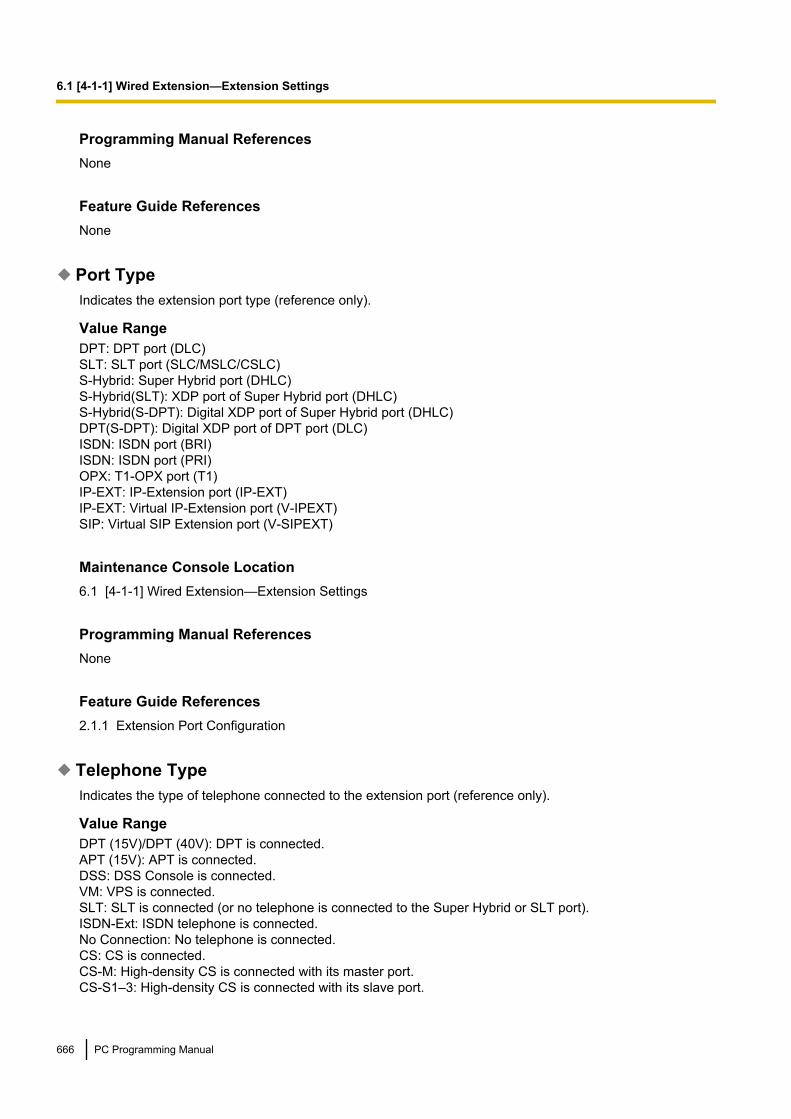
Programming Manual ReferencesNone
Feature Guide ReferencesNone
Port TypeIndicates the extension port type (reference only).
Value RangeDPT: DPT port (DLC)SLT: SLT port (SLC/MSLC/CSLC)S-Hybrid: Super Hybrid port (DHLC)S-Hybrid(SLT): XDP port of Super Hybrid port (DHLC)S-Hybrid(S-DPT): Digital XDP port of Super Hybrid port (DHLC)DPT(S-DPT): Digital XDP port of DPT port (DLC)ISDN: ISDN port (BRI)ISDN: ISDN port (PRI)OPX: T1-OPX port (T1)IP-EXT: IP-Extension port (IP-EXT)IP-EXT: Virtual IP-Extension port (V-IPEXT)SIP: Virtual SIP Extension port (V-SIPEXT)
Maintenance Console Location6.1 [4-1-1] Wired Extension—Extension Settings
Programming Manual ReferencesNone
Feature Guide References2.1.1 Extension Port Configuration
Telephone TypeIndicates the type of telephone connected to the extension port (reference only).
Value RangeDPT (15V)/DPT (40V): DPT is connected.APT (15V): APT is connected.DSS: DSS Console is connected.VM: VPS is connected.SLT: SLT is connected (or no telephone is connected to the Super Hybrid or SLT port).ISDN-Ext: ISDN telephone is connected.No Connection: No telephone is connected.CS: CS is connected.CS-M: High-density CS is connected with its master port.CS-S1–3: High-density CS is connected with its slave port.
666 PC Programming Manual
6.1 [4-1-1] Wired Extension—Extension Settings

IP-EXT: IP-PT belonging to the IP-EXT card is connected.IP-PT: IP-PT belonging to the V-IPEXT card is connected.SIP: SIP Extension is connected.
Maintenance Console Location6.1 [4-1-1] Wired Extension—Extension Settings
Programming Manual ReferencesNone
Feature Guide ReferencesNone
User GroupSpecifies the extension user group to which the extension belongs. Extension user groups are used to composetenants, call pickup groups and paging groups.
Value RangeFor KX-TDE100/KX-TDE200:1–32
For KX-TDE600:1–96
Maintenance Console Location6.1 [4-1-1] Wired Extension—Extension Settings
Programming Manual ReferencesNone
Feature Guide References2.2.2 Group2.2.3 Tenant Service
COSSpecifies the COS of the extension.
Value Range1–64
Maintenance Console Location6.1 [4-1-1] Wired Extension—Extension Settings
PC Programming Manual 667
6.1 [4-1-1] Wired Extension—Extension Settings

Programming Manual References4.12 [2-7-1] Class of Service—COS Settings
Feature Guide References2.2.1 Class of Service (COS)
Extension PINSpecifies the PIN of the extension.
CAUTIONThere is a risk that fraudulent telephone calls will be made if a third party discovers a personal identificationnumber (PIN) (verification code PIN or extension PIN) of the PBX.The cost of such calls will be billed to the owner/renter of the PBX.To protect the PBX from this kind of fraudulent use, we strongly recommend:a. Keeping PINs secret.b. Selecting complex, random PINs that cannot be easily guessed.c. Changing PINs frequently.
Value RangeMax. 10 digits (consisting of 0-9)
Maintenance Console Location6.1 [4-1-1] Wired Extension—Extension Settings
Programming Manual ReferencesNone
Feature Guide References1.28.1 Extension Personal Identification Number (PIN)
Intercept Destination ShelfIndicates the shelf type and/or position (reference only).
Value RangeFor KX-TDE100/KX-TDE200:Physical, Virtual
For KX-TDE600:Shelf number, Virtual
Maintenance Console Location6.1 [4-1-1] Wired Extension—Extension Settings
668 PC Programming Manual
6.1 [4-1-1] Wired Extension—Extension Settings

Programming Manual ReferencesNone
Feature Guide ReferencesNone
SlotIndicates the slot position of each extension card (reference only).
Value RangeSlot number
Maintenance Console Location6.1 [4-1-1] Wired Extension—Extension Settings
Programming Manual ReferencesNone
Feature Guide ReferencesNone
PortIndicates the port number (reference only).
Value RangePort number
Maintenance Console Location6.1 [4-1-1] Wired Extension—Extension Settings
Programming Manual References3.24 [1-1] Slot—Port Property - Extension Port
Feature Guide ReferencesNone
Extension NumberSpecifies the extension number of the extension.
Value RangeMax. 5 digits (consisting of 0–9)
PC Programming Manual 669
6.1 [4-1-1] Wired Extension—Extension Settings

Maintenance Console Location6.1 [4-1-1] Wired Extension—Extension Settings
Programming Manual References3.25 [1-1] Slot—Port Property - Extension Port—Connection Command
Feature Guide ReferencesNone
Extension NameSpecifies the name of the extension.
Value RangeMax. 20 characters
Maintenance Console Location6.1 [4-1-1] Wired Extension—Extension Settings
Programming Manual ReferencesNone
Feature Guide ReferencesNone
Intercept Destination—When called party does not answer—Day, Lunch,Break, Night
Specifies the Intercept Routing destination of calls in each time mode for Intercept Routing–No Answer andIntercept Routing–DND.Note that Intercept Routing–Busy calls are routed using Intercept Destination—When Called Party isBusy below.
Value RangeMax. 32 digits (consisting of 0–9, *, #, [ ] [Secret], and P [Pause])
Maintenance Console Location6.1 [4-1-1] Wired Extension—Extension Settings
Programming Manual References6.1 [4-1-1] Wired Extension—Extension Settings—Intercept Destination— Intercept Destination—WhenCalled Party is Busy
670 PC Programming Manual
6.1 [4-1-1] Wired Extension—Extension Settings

Feature Guide References1.1.1.6 Intercept Routing
Intercept Destination—When Called Party is BusySpecifies the Intercept Routing destination of calls when the extension is busy.
Value RangeMax. 32 digits (consisting of 0–9, *, #, [ ] [Secret], and P [Pause])
Maintenance Console Location6.1 [4-1-1] Wired Extension—Extension Settings
Programming Manual ReferencesNone
Feature Guide References1.1.1.6 Intercept Routing
Intercept No Answer TimeShelfIndicates the shelf type and/or position (reference only).
Value RangeFor KX-TDE100/KX-TDE200:Physical, Virtual
For KX-TDE600:Shelf number, Virtual
Maintenance Console Location6.1 [4-1-1] Wired Extension—Extension Settings
Programming Manual ReferencesNone
Feature Guide ReferencesNone
SlotIndicates the slot position of each extension card (reference only).
PC Programming Manual 671
6.1 [4-1-1] Wired Extension—Extension Settings

Value RangeSlot number
Maintenance Console Location6.1 [4-1-1] Wired Extension—Extension Settings
Programming Manual ReferencesNone
Feature Guide ReferencesNone
PortIndicates the port number (reference only).
Value RangePort number
Maintenance Console Location6.1 [4-1-1] Wired Extension—Extension Settings
Programming Manual References3.24 [1-1] Slot—Port Property - Extension Port
Feature Guide ReferencesNone
Extension NumberSpecifies the extension number of the extension.
Value RangeMax. 5 digits (consisting of 0–9)
Maintenance Console Location6.1 [4-1-1] Wired Extension—Extension Settings
Programming Manual References3.25 [1-1] Slot—Port Property - Extension Port—Connection Command
672 PC Programming Manual
6.1 [4-1-1] Wired Extension—Extension Settings

Feature Guide ReferencesNone
Extension NameSpecifies the name of the extension.
Value RangeMax. 20 characters
Maintenance Console Location6.1 [4-1-1] Wired Extension—Extension Settings
Programming Manual ReferencesNone
Feature Guide ReferencesNone
Intercept No Answer Time—Day, Lunch, Break, NightSpecifies the length of time until an unanswered call is redirected to the intercept routing destination in eachtime mode.When this setting is set to "0", the system timer is used.
Value Range0–240 s
Maintenance Console Location6.1 [4-1-1] Wired Extension—Extension Settings
Programming Manual References4.5 [2-3] Timers & Counters—Dial / IRNA / Recall / Tone— Intercept Routing No Answer (IRNA)—Day,Lunch, Break, Night
Feature Guide References1.1.1.6 Intercept Routing
ISDN CLIPShelfIndicates the shelf type and/or position (reference only).
PC Programming Manual 673
6.1 [4-1-1] Wired Extension—Extension Settings

Value RangeFor KX-TDE100/KX-TDE200:Physical, Virtual
For KX-TDE600:Shelf number, Virtual
Maintenance Console Location6.1 [4-1-1] Wired Extension—Extension Settings
Programming Manual ReferencesNone
Feature Guide ReferencesNone
SlotIndicates the slot position of each extension card (reference only).
Value RangeSlot number
Maintenance Console Location6.1 [4-1-1] Wired Extension—Extension Settings
Programming Manual ReferencesNone
Feature Guide ReferencesNone
PortIndicates the port number (reference only).
Value RangePort number
Maintenance Console Location6.1 [4-1-1] Wired Extension—Extension Settings
674 PC Programming Manual
6.1 [4-1-1] Wired Extension—Extension Settings

Programming Manual References3.24 [1-1] Slot—Port Property - Extension Port
Feature Guide ReferencesNone
Extension NumberSpecifies the extension number of the extension.
Value RangeMax. 5 digits (consisting of 0–9)
Maintenance Console Location6.1 [4-1-1] Wired Extension—Extension Settings
Programming Manual References3.25 [1-1] Slot—Port Property - Extension Port—Connection Command
Feature Guide ReferencesNone
Extension NameSpecifies the name of the extension.
Value RangeMax. 20 characters
Maintenance Console Location6.1 [4-1-1] Wired Extension—Extension Settings
Programming Manual ReferencesNone
Feature Guide ReferencesNone
CLIP IDSpecifies the CLIP number sent to the public network to show on the called party’s telephone display whenmaking a trunk call.
PC Programming Manual 675
6.1 [4-1-1] Wired Extension—Extension Settings

Value RangeMax. 16 digits (consisting of 0–9, *, and #)
Maintenance Console Location6.1 [4-1-1] Wired Extension—Extension Settings
Programming Manual ReferencesNone
Feature Guide References1.21.1.2 Calling/Connected Line Identification Presentation (CLIP/COLP)
CLIP on Extension/COSelects the CLIP number to show on the called party’s telephone.
Value RangeExtension: Show the CLIP number specified in CLIP ID on the Option 1 tab.CO: Show the CLIP number specified in Subscriber Number in 3.33 [1-1] Slot—Port Property - BRIPort or 3.35 [1-1] Slot—Port Property - PRI Port.
Maintenance Console Location6.1 [4-1-1] Wired Extension—Extension Settings
Programming Manual References3.33 [1-1] Slot—Port Property - BRI Port—ISDN CO— Subscriber Number3.35 [1-1] Slot—Port Property - PRI Port—CO Setting— Subscriber Number6.1 [4-1-1] Wired Extension—Extension Settings—ISDN CLIP— CLIP ID
Feature Guide References1.21.1.2 Calling/Connected Line Identification Presentation (CLIP/COLP)
CLIRSpecifies whether to restrict the display of the CLIP number on the called party’s telephone when making apublic network trunk call.
Value RangeDisable, Enable
Maintenance Console Location6.1 [4-1-1] Wired Extension—Extension Settings
676 PC Programming Manual
6.1 [4-1-1] Wired Extension—Extension Settings

Programming Manual ReferencesNone
Feature Guide References1.21.1.2 Calling/Connected Line Identification Presentation (CLIP/COLP)
COLRSpecifies whether to restrict the display of the CLIP number of the extension on the caller’s telephone displaywhen answering a call.
Value RangeDisable, Enable
Maintenance Console Location6.1 [4-1-1] Wired Extension—Extension Settings
Programming Manual ReferencesNone
Feature Guide References1.21.1.2 Calling/Connected Line Identification Presentation (CLIP/COLP)
Option 1ShelfIndicates the shelf type and/or position (reference only).
Value RangeFor KX-TDE100/KX-TDE200:Physical, Virtual
For KX-TDE600:Shelf number, Virtual
Maintenance Console Location6.1 [4-1-1] Wired Extension—Extension Settings
Programming Manual ReferencesNone
Feature Guide ReferencesNone
PC Programming Manual 677
6.1 [4-1-1] Wired Extension—Extension Settings
SlotIndicates the slot position of each extension card (reference only).
Value RangeSlot number
Maintenance Console Location6.1 [4-1-1] Wired Extension—Extension Settings
Programming Manual References3.1 [1-1] Slot
Feature Guide ReferencesNone
PortIndicates the port number (reference only).
Value RangePort number
Maintenance Console Location6.1 [4-1-1] Wired Extension—Extension Settings
Programming Manual References3.24 [1-1] Slot—Port Property - Extension Port
Feature Guide ReferencesNone
Extension NumberSpecifies the extension number of the extension.
Value RangeMax. 5 digits (consisting of 0–9)
Maintenance Console Location6.1 [4-1-1] Wired Extension—Extension Settings
Programming Manual References3.25 [1-1] Slot—Port Property - Extension Port—Connection Command
678 PC Programming Manual
6.1 [4-1-1] Wired Extension—Extension Settings

Feature Guide ReferencesNone
Extension NameSpecifies the name of the extension.
Value RangeMax. 20 characters
Maintenance Console Location6.1 [4-1-1] Wired Extension—Extension Settings
Programming Manual ReferencesNone
Feature Guide ReferencesNone
Wireless XDPSpecifies the extension number of the PS with which Wireless XDP Parallel Mode is established. To enableWireless XDP Parallel Mode, the PS must be turned off once and then turned on after assigning this setting.When changing the port type of an extension port in DPT Type—Type on the 3.24 [1-1] Slot—PortProperty - Extension Port screen, the Wireless XDP setting must be deleted first.
Value RangeMax. 5 digits (consisting of 0–9)
Maintenance Console Location6.1 [4-1-1] Wired Extension—Extension Settings
Programming Manual ReferencesNone
Feature Guide References1.25.5 Wireless XDP Parallel Mode
Ring Pattern TableSpecifies the Ring Tone Pattern Table to be used by the extension.
Value Range1–8
PC Programming Manual 679
6.1 [4-1-1] Wired Extension—Extension Settings
Maintenance Console Location6.1 [4-1-1] Wired Extension—Extension Settings
Programming Manual References4.15 [2-8-1] Ring Tone Patterns—Call from CO4.16 [2-8-2] Ring Tone Patterns—Call from Doorphone4.17 [2-8-3] Ring Tone Patterns—Call from Others
Feature Guide References1.1.3.2 Ring Tone Pattern Selection
Programmed Mailbox No.Specifies the mailbox number of the extension’s mailbox for Voice Processing Systems (VPS) with DTMFIntegration.
Value RangeMax. 16 digits (consisting of 0–9, *, and #)
Maintenance Console Location6.1 [4-1-1] Wired Extension—Extension Settings
Programming Manual ReferencesNone
Feature Guide References1.24.2 Voice Mail DTMF Integration
Transfer Recall DestinationSpecifies the transfer recall destination when an extension user transfers a call with the Call Transfer withoutAnnouncement feature and the transferred call is not answered within a certain time period.
Value RangeMax. 5 digits (consisting of 0–9)
Maintenance Console Location6.1 [4-1-1] Wired Extension—Extension Settings
Programming Manual ReferencesNone
Feature Guide References1.12.1 Call Transfer
680 PC Programming Manual
6.1 [4-1-1] Wired Extension—Extension Settings

ARS Itemised CodeSpecifies the itemised billing code used by the ARS feature for identifying calls made from the extension foraccounting and billing purposes.
Value RangeMax. 10 digits (consisting of 0–9, *, and #)
Maintenance Console Location6.1 [4-1-1] Wired Extension—Extension Settings
Programming Manual References10.6 [8-5] Carrier
Feature Guide References1.9.6 Verification Code Entry1.10.1 Automatic Route Selection (ARS)
Option 2ShelfIndicates the shelf type and/or position (reference only).
Value RangeFor KX-TDE100/KX-TDE200:Physical, Virtual
For KX-TDE600:Shelf number, Virtual
Maintenance Console Location6.1 [4-1-1] Wired Extension—Extension Settings
Programming Manual ReferencesNone
Feature Guide ReferencesNone
SlotIndicates the slot position of each extension card (reference only).
Value RangeSlot number
PC Programming Manual 681
6.1 [4-1-1] Wired Extension—Extension Settings

Maintenance Console Location6.1 [4-1-1] Wired Extension—Extension Settings
Programming Manual References3.1 [1-1] Slot
Feature Guide ReferencesNone
PortIndicates the port number (reference only).
Value RangePort number
Maintenance Console Location6.1 [4-1-1] Wired Extension—Extension Settings
Programming Manual References3.24 [1-1] Slot—Port Property - Extension Port
Feature Guide ReferencesNone
Extension NumberSpecifies the extension number of the extension.
Value RangeMax. 5 digits (consisting of 0–9)
Maintenance Console Location6.1 [4-1-1] Wired Extension—Extension Settings
Programming Manual References3.25 [1-1] Slot—Port Property - Extension Port—Connection Command
Feature Guide ReferencesNone
682 PC Programming Manual
6.1 [4-1-1] Wired Extension—Extension Settings

Extension NameSpecifies the name of the extension.
Value RangeMax. 20 characters
Maintenance Console Location6.1 [4-1-1] Wired Extension—Extension Settings
Programming Manual ReferencesNone
Feature Guide ReferencesNone
Manual C. Waiting for Extension CallSelects the method of receiving call waiting notification from other extensions.
Value RangeOff: No notificationBSS: Tone from the handset or built-in speakerOHCA: Voice from the built-in speakerW-OHCA: Voice from the handset
Maintenance Console Location6.1 [4-1-1] Wired Extension—Extension Settings
Programming Manual ReferencesNone
Feature Guide References1.1.3.3 Call Waiting1.8.4.1 Second Call Notification to Busy Extension—SUMMARY
Automatic C. WaitingSpecifies whether to receive call waiting notifications for calls from a trunk, doorphone calls, and calls via anincoming call distribution group.
Value RangeOff, On
Maintenance Console Location6.1 [4-1-1] Wired Extension—Extension Settings
PC Programming Manual 683
6.1 [4-1-1] Wired Extension—Extension Settings

Programming Manual ReferencesNone
Feature Guide References1.1.3.3 Call Waiting
Pickup Dial SetSets or cancels the Hot Line feature. The number specified in Pickup Dial No. on this screen is dialledautomatically after going off-hook when the Hot Line feature is active.
Value RangeOff, On
Maintenance Console Location6.1 [4-1-1] Wired Extension—Extension Settings
Programming Manual References4.5 [2-3] Timers & Counters—Dial / IRNA / Recall / Tone— Dial—Hot Line (Pickup Dial) Start
Feature Guide References1.6.1.7 Hot Line
Pickup Dial No.Specifies the number to be dialled automatically after going off-hook when the Hot Line feature is active.
Value RangeMax. 32 digits (consisting of 0–9, *, #, T [Transfer], [ ] [Secret], P [Pause], and F [Flash])
Maintenance Console Location6.1 [4-1-1] Wired Extension—Extension Settings
Programming Manual ReferencesNone
Feature Guide References1.6.1.7 Hot Line
Data ModeSets or cancels the protection against tones or interruptions from other extensions during communication.
684 PC Programming Manual
6.1 [4-1-1] Wired Extension—Extension Settings

Value RangeOff, On
Maintenance Console Location6.1 [4-1-1] Wired Extension—Extension Settings
Programming Manual ReferencesNone
Feature Guide References1.11.5 Data Line Security
Option 3ShelfIndicates the shelf type and/or position (reference only).
Value RangeFor KX-TDE100/KX-TDE200:Physical, Virtual
For KX-TDE600:Shelf number, Virtual
Maintenance Console Location6.1 [4-1-1] Wired Extension—Extension Settings
Programming Manual ReferencesNone
Feature Guide ReferencesNone
SlotIndicates the slot position of each extension card (reference only).
Value RangeSlot number
Maintenance Console Location6.1 [4-1-1] Wired Extension—Extension Settings
PC Programming Manual 685
6.1 [4-1-1] Wired Extension—Extension Settings

Programming Manual References3.1 [1-1] Slot
Feature Guide ReferencesNone
PortIndicates the port number (reference only).
Value RangePort number
Maintenance Console Location6.1 [4-1-1] Wired Extension—Extension Settings
Programming Manual References3.24 [1-1] Slot—Port Property - Extension Port
Feature Guide ReferencesNone
Extension NumberSpecifies the extension number of the extension.
Value RangeMax. 5 digits (consisting of 0–9)
Maintenance Console Location6.1 [4-1-1] Wired Extension—Extension Settings
Programming Manual References3.25 [1-1] Slot—Port Property - Extension Port—Connection Command
Feature Guide ReferencesNone
Extension NameSpecifies the name of the extension.
Value RangeMax. 20 characters
686 PC Programming Manual
6.1 [4-1-1] Wired Extension—Extension Settings

Maintenance Console Location6.1 [4-1-1] Wired Extension—Extension Settings
Programming Manual ReferencesNone
Feature Guide ReferencesNone
Call Pickup DenySpecifies whether calls can be picked up by other extensions.
Value RangeDisable: Allows other extension users to pick up calls to your extensionEnable: Prevents other extension users from picking up calls to your extension
Maintenance Console Location6.1 [4-1-1] Wired Extension—Extension Settings
Programming Manual ReferencesNone
Feature Guide References1.4.1.3 Call Pickup
Executive Override DenySpecifies whether calls can be interrupted by other extensions.
Value RangeDisable: Allows other extension users to interrupt an existing callEnable: Prevents other extension users from interrupting an existing call
Maintenance Console Location6.1 [4-1-1] Wired Extension—Extension Settings
Programming Manual ReferencesNone
Feature Guide References1.8.2 Executive Busy Override
PC Programming Manual 687
6.1 [4-1-1] Wired Extension—Extension Settings
Absent MessageSpecifies the Personal Absent Message which, unlike the System Absent Message, can be customised foreach extension.
Value RangeMax. 16 characters
Maintenance Console Location6.1 [4-1-1] Wired Extension—Extension Settings
Programming Manual ReferencesNone
Feature Guide References1.19.2 Absent Message
Charge LimitSpecifies the maximum limit of call charges allowed for the extension. When this limit is reached, the extensioncannot be used to make further trunk calls.The number of decimal places that can be specified here depends on the value set in Charge Options—Digits After Decimal Point in 8.2 [6-2] Hotel & Charge.
Value Range0–9999999
Maintenance Console Location6.1 [4-1-1] Wired Extension—Extension Settings
Programming Manual References8.2 [6-2] Hotel & Charge
Feature Guide References1.9.2 Budget Management
Intercom Call by VoiceSelects the method of receiving intercom calls. When Deny Voice Call is selected, the extension will alwaysring when receiving calls, regardless of how the caller wants to make the call.
Value RangeTone Call, Voice Call, Deny Voice Call
Maintenance Console Location6.1 [4-1-1] Wired Extension—Extension Settings
688 PC Programming Manual
6.1 [4-1-1] Wired Extension—Extension Settings

Programming Manual ReferencesNone
Feature Guide References1.5.3 Intercom Call
Option 4ShelfIndicates the shelf type and/or position (reference only).
Value RangeFor KX-TDE100/KX-TDE200:Physical, Virtual
For KX-TDE600:Shelf number, Virtual
Maintenance Console Location6.1 [4-1-1] Wired Extension—Extension Settings
Programming Manual ReferencesNone
Feature Guide ReferencesNone
SlotIndicates the slot position of each extension card (reference only).
Value RangeSlot number
Maintenance Console Location6.1 [4-1-1] Wired Extension—Extension Settings
Programming Manual References3.1 [1-1] Slot
Feature Guide ReferencesNone
PC Programming Manual 689
6.1 [4-1-1] Wired Extension—Extension Settings

PortIndicates the port number (reference only).
Value RangePort number
Maintenance Console Location6.1 [4-1-1] Wired Extension—Extension Settings
Programming Manual References3.24 [1-1] Slot—Port Property - Extension Port
Feature Guide ReferencesNone
Extension NumberSpecifies the extension number of the extension.
Value RangeMax. 5 digits (consisting of 0–9)
Maintenance Console Location6.1 [4-1-1] Wired Extension—Extension Settings
Programming Manual References3.25 [1-1] Slot—Port Property - Extension Port—Connection Command
Feature Guide ReferencesNone
Extension NameSpecifies the name of the extension.
Value RangeMax. 20 characters
Maintenance Console Location6.1 [4-1-1] Wired Extension—Extension Settings
Programming Manual ReferencesNone
690 PC Programming Manual
6.1 [4-1-1] Wired Extension—Extension Settings

Feature Guide ReferencesNone
Outgoing Preferred LineSelects the line to be seized after going off-hook to make a call.
Value RangeNo Line: No line is seized.Idle: An idle trunk is seized automatically from the programmed trunk groups.ICM/PDN: An extension line is seized, or, for a PDN extension, an idle PDN button is selected.F-1–F-84: A trunk programmed for a flexible button (F-1–F-84) is seized. A flexible button customised as aSingle-CO, Group-CO, Loop-CO, or ICD Group button must be selected.
Maintenance Console Location6.1 [4-1-1] Wired Extension—Extension Settings
Programming Manual References6.5 [4-1-4] Wired Extension—Flexible Button
Feature Guide References1.5.5.2 Line Preference—Outgoing
Incoming Preferred LineSelects the line on which an incoming call is answered after going off-hook.Note that even if a specific PDN button is selected here, a call ringing at any PDN button on the extension willbe answered when going off-hook.
Value RangeNo Line: No line is selected. Select a line by pressing the desired Line Access button to answer a call.Ringing Line: The longest ringing call is selected.PDN: The call arriving at any PDN button is selected.F-1–F-84: The call arriving at a flexible button (F-1–F-84) is selected. A flexible button customised as aSingle-CO, Group-CO, Loop-CO, or ICD Group button must be selected.
Maintenance Console Location6.1 [4-1-1] Wired Extension—Extension Settings
Programming Manual References6.5 [4-1-4] Wired Extension—Flexible Button
Feature Guide References1.4.1.2 Line Preference—Incoming
PC Programming Manual 691
6.1 [4-1-1] Wired Extension—Extension Settings

Call Waiting Tone TypeSelects the type of Call Waiting tone sent to the busy extension.
Value RangeCW Tone 1, CW Tone 2
Maintenance Console Location6.1 [4-1-1] Wired Extension—Extension Settings
Programming Manual ReferencesNone
Feature Guide References1.8.4.2 Call Waiting Tone
LCS Recording ModeSpecifies whether to continue or stop recording the message in the extension’s mailbox when the extensionuser answers a call that was being monitored.
Value RangeStop Record, Keep Record
Maintenance Console Location6.1 [4-1-1] Wired Extension—Extension Settings
Programming Manual ReferencesNone
Feature Guide References1.24.3 Voice Mail DPT (Digital) Integration
LCS Answer ModeSpecifies whether the extension’s mailbox is monitored in Hands-free or Private mode.
Value RangeHands free: Monitor through the built-in speakerPrivate: Monitor through the handset or the built-in speaker after hearing a warning tone
Maintenance Console Location6.1 [4-1-1] Wired Extension—Extension Settings
692 PC Programming Manual
6.1 [4-1-1] Wired Extension—Extension Settings
Programming Manual ReferencesNone
Feature Guide References1.11.1 Hands-free Operation1.24.3 Voice Mail DPT (Digital) Integration
Option 5ShelfIndicates the shelf type and/or position (reference only).
Value RangeFor KX-TDE100/KX-TDE200:Physical, Virtual
For KX-TDE600:Shelf number, Virtual
Maintenance Console Location6.1 [4-1-1] Wired Extension—Extension Settings
Programming Manual ReferencesNone
Feature Guide ReferencesNone
SlotIndicates the slot position of each extension card (reference only).
Value RangeSlot number
Maintenance Console Location6.1 [4-1-1] Wired Extension—Extension Settings
Programming Manual References3.1 [1-1] Slot
Feature Guide ReferencesNone
PC Programming Manual 693
6.1 [4-1-1] Wired Extension—Extension Settings
PortIndicates the port number (reference only).
Value RangePort number
Maintenance Console Location6.1 [4-1-1] Wired Extension—Extension Settings
Programming Manual References3.24 [1-1] Slot—Port Property - Extension Port
Feature Guide ReferencesNone
Extension NumberSpecifies the extension number of the extension.
Value RangeMax. 5 digits (consisting of 0–9)
Maintenance Console Location6.1 [4-1-1] Wired Extension—Extension Settings
Programming Manual References3.25 [1-1] Slot—Port Property - Extension Port—Connection Command
Feature Guide ReferencesNone
Extension NameSpecifies the name of the extension.
Value RangeMax. 20 characters
Maintenance Console Location6.1 [4-1-1] Wired Extension—Extension Settings
Programming Manual ReferencesNone
694 PC Programming Manual
6.1 [4-1-1] Wired Extension—Extension Settings

Feature Guide ReferencesNone
Display LanguageSelects the display language of the extension telephone.
Value RangeLanguage1–Language5
Maintenance Console Location6.1 [4-1-1] Wired Extension—Extension Settings
Programming Manual ReferencesNone
Feature Guide References1.20.4 Display Information
Incoming Call DisplaySelects which caller information is shown on the first line of the extension’s display.
Value RangeCaller ID Name, CO Line Name, DDI/DID Name
Maintenance Console Location6.1 [4-1-1] Wired Extension—Extension Settings
Programming Manual ReferencesNone
Feature Guide References1.20.4 Display Information
Automatic LCD Switch when Start TalkingEnables the first line of the display to show the call duration automatically after answering a trunk call.
Value RangeDisable, Enable
Maintenance Console Location6.1 [4-1-1] Wired Extension—Extension Settings
PC Programming Manual 695
6.1 [4-1-1] Wired Extension—Extension Settings

Programming Manual ReferencesNone
Feature Guide References1.20.4 Display Information
Key Pad ToneSpecifies whether key pad tones are heard when dialling.
Value RangeOff, On
Maintenance Console Location6.1 [4-1-1] Wired Extension—Extension Settings
Programming Manual ReferencesNone
Feature Guide ReferencesNone
Automatic Answer for CO CallEnables the extension to answer an incoming trunk call automatically after a certain number of rings withoutgoing off-hook, when Hands-free Answerback has been set on the extension. This setting is only effectivewhen Forced Automatic Answer on this screen has been set to Off.
Value RangeDisable, Enable
Maintenance Console Location6.1 [4-1-1] Wired Extension—Extension Settings
Programming Manual ReferencesNone
Feature Guide References1.4.1.4 Hands-free Answerback
Option 6ShelfIndicates the shelf type and/or position (reference only).
696 PC Programming Manual
6.1 [4-1-1] Wired Extension—Extension Settings

Value RangeFor KX-TDE100/KX-TDE200:Physical, Virtual
For KX-TDE600:Shelf number, Virtual
Maintenance Console Location6.1 [4-1-1] Wired Extension—Extension Settings
Programming Manual ReferencesNone
Feature Guide ReferencesNone
SlotIndicates the slot position of each extension card (reference only).
Value RangeSlot number
Maintenance Console Location6.1 [4-1-1] Wired Extension—Extension Settings
Programming Manual References3.1 [1-1] Slot
Feature Guide ReferencesNone
PortIndicates the port number (reference only).
Value RangePort number
Maintenance Console Location6.1 [4-1-1] Wired Extension—Extension Settings
PC Programming Manual 697
6.1 [4-1-1] Wired Extension—Extension Settings

Programming Manual References3.24 [1-1] Slot—Port Property - Extension Port
Feature Guide ReferencesNone
Extension NumberSpecifies the extension number of the extension.
Value RangeMax. 5 digits (consisting of 0–9)
Maintenance Console Location6.1 [4-1-1] Wired Extension—Extension Settings
Programming Manual References3.25 [1-1] Slot—Port Property - Extension Port—Connection Command
Feature Guide ReferencesNone
Extension NameSpecifies the name of the extension.
Value RangeMax. 20 characters
Maintenance Console Location6.1 [4-1-1] Wired Extension—Extension Settings
Programming Manual ReferencesNone
Feature Guide ReferencesNone
Forced Automatic AnswerSpecifies whether the extension automatically answers all incoming calls (both intercom and trunk calls) withoutgoing off-hook, regardless of the Hands-free Answerback setting.
698 PC Programming Manual
6.1 [4-1-1] Wired Extension—Extension Settings
Value RangeOff, On
Maintenance Console Location6.1 [4-1-1] Wired Extension—Extension Settings
Programming Manual ReferencesNone
Feature Guide ReferencesNone
Flexible Button Programming ModeSpecifies whether the extension user can modify all flexible buttons without limitation, or only the One-touchDialling buttons. When the mode is set to One-touch Dial, there is no need to enter "2" before the numberwhen customising a One-touch Dialling button.
Value RangeNo Limitation, One-touch Dial
Maintenance Console Location6.1 [4-1-1] Wired Extension—Extension Settings
Programming Manual ReferencesNone
Feature Guide ReferencesNone
ICM ToneSelects the ring tone for incoming calls arriving at the INTERCOM button or PDN buttons. Note that the ringtone specified here is applied to all PDN buttons on an extension.
Value RangeKX-DT300 series (except KX-DT321)/KX-T7600 series (except KX-T7665)/IP-PT (except KX-NT265/KX-NT321): 1–30KX-DT321/KX-T7665/KX-NT265/KX-NT321: 1–8 (Even if ring tone 9–30 is selected, ring tone 1 is heard.)Other telephones: 1–8 (Even if ring tone 9–30 is selected, ring tone 2 is heard.)
Maintenance Console Location6.1 [4-1-1] Wired Extension—Extension Settings
PC Programming Manual 699
6.1 [4-1-1] Wired Extension—Extension Settings

Programming Manual ReferencesNone
Feature Guide ReferencesNone
Display Lock / SVM LockLocks or unlocks the Incoming Call Log and Simplified Voice Message Log display (i.e., specifies whetherother extension users can see the Incoming Call Log and SVM Log information at the extension).
Value RangeUnlock, Lock
Maintenance Console Location6.1 [4-1-1] Wired Extension—Extension Settings
Programming Manual ReferencesNone
Feature Guide References1.18.2 Incoming Call Log1.17.7 Built-in Simplified Voice Message (SVM)
Paging DenySpecifies whether paging of the extension from other extensions is enabled.
Value RangeDisable, Enable
Maintenance Console Location6.1 [4-1-1] Wired Extension—Extension Settings
Programming Manual ReferencesNone
Feature Guide References1.16.1 Paging
Option 7ShelfIndicates the shelf type and/or position (reference only).
700 PC Programming Manual
6.1 [4-1-1] Wired Extension—Extension Settings
Value RangeFor KX-TDE100/KX-TDE200:Physical, Virtual
For KX-TDE600:Shelf number, Virtual
Maintenance Console Location6.1 [4-1-1] Wired Extension—Extension Settings
Programming Manual ReferencesNone
Feature Guide ReferencesNone
SlotIndicates the slot position of each extension card (reference only).
Value RangeSlot number
Maintenance Console Location6.1 [4-1-1] Wired Extension—Extension Settings
Programming Manual References3.1 [1-1] Slot
Feature Guide ReferencesNone
PortIndicates the port number (reference only).
Value RangePort number
Maintenance Console Location6.1 [4-1-1] Wired Extension—Extension Settings
PC Programming Manual 701
6.1 [4-1-1] Wired Extension—Extension Settings

Programming Manual References3.24 [1-1] Slot—Port Property - Extension Port
Feature Guide ReferencesNone
Extension NumberSpecifies the extension number of the extension.
Value RangeMax. 5 digits (consisting of 0–9)
Maintenance Console Location6.1 [4-1-1] Wired Extension—Extension Settings
Programming Manual References3.25 [1-1] Slot—Port Property - Extension Port—Connection Command
Feature Guide ReferencesNone
Extension NameSpecifies the name of the extension.
Value RangeMax. 20 characters
Maintenance Console Location6.1 [4-1-1] Wired Extension—Extension Settings
Programming Manual ReferencesNone
Feature Guide ReferencesNone
Character Input ModeSelects the character table to be used for entering characters.
Value RangeTable 1: Standard mode
702 PC Programming Manual
6.1 [4-1-1] Wired Extension—Extension Settings

Table 2: Option mode
Maintenance Console Location6.1 [4-1-1] Wired Extension—Extension Settings
Programming Manual ReferencesNone
Feature Guide ReferencesNone
Flash Mode during CO ConversationSelects the function of the FLASH/RECALL button during a trunk conversation.
Value RangeEFA, Terminate, Flash Recall
Maintenance Console Location6.1 [4-1-1] Wired Extension—Extension Settings
Programming Manual ReferencesNone
Feature Guide References1.11.6 Flash/Recall/Terminate1.11.7 External Feature Access (EFA)
Incoming Call Log MemorySpecifies the number of incoming trunk calls that are retained in the extension’s Incoming Call Log memory.
Value Range0–100
Maintenance Console Location6.1 [4-1-1] Wired Extension—Extension Settings
Programming Manual ReferencesNone
Feature Guide References1.18.2 Incoming Call Log
PC Programming Manual 703
6.1 [4-1-1] Wired Extension—Extension Settings

Outgoing Call Log MemorySpecifies the number of telephone numbers dialled by the extension that are retained in the extension’sOutgoing Call Log memory.
Value Range1–100
Maintenance Console Location6.1 [4-1-1] Wired Extension—Extension Settings
Programming Manual ReferencesNone
Feature Guide References1.6.1.4 Last Number Redial
ISDN BearerSelects the ISDN bearer mode. When Automatic is selected, the bearer mode is set automatically dependingon the extension’s telephone type as follows:PT: SpeechSLT: Audio
Value RangeAutomatic, Speech, Audio
Maintenance Console Location6.1 [4-1-1] Wired Extension—Extension Settings
Programming Manual ReferencesNone
Feature Guide References1.21.1.1 Integrated Services Digital Network (ISDN)—SUMMARY
Option 8ShelfIndicates the shelf type and/or position (reference only).
Value RangeFor KX-TDE100/KX-TDE200:Physical, Virtual
704 PC Programming Manual
6.1 [4-1-1] Wired Extension—Extension Settings

For KX-TDE600:Shelf number, Virtual
Maintenance Console Location6.1 [4-1-1] Wired Extension—Extension Settings
Programming Manual ReferencesNone
Feature Guide ReferencesNone
SlotIndicates the slot position of each extension card (reference only).
Value RangeSlot number
Maintenance Console Location6.1 [4-1-1] Wired Extension—Extension Settings
Programming Manual ReferencesNone
Feature Guide ReferencesNone
PortIndicates the port number (reference only).
Value RangePort number
Maintenance Console Location6.1 [4-1-1] Wired Extension—Extension Settings
Programming Manual References3.24 [1-1] Slot—Port Property - Extension Port
Feature Guide ReferencesNone
PC Programming Manual 705
6.1 [4-1-1] Wired Extension—Extension Settings

Extension NumberSpecifies the extension number of the extension.
Value RangeMax. 5 digits (consisting of 0–9)
Maintenance Console Location6.1 [4-1-1] Wired Extension—Extension Settings
Programming Manual References3.25 [1-1] Slot—Port Property - Extension Port—Connection Command
Feature Guide ReferencesNone
Extension NameSpecifies the name of the extension.
Value RangeMax. 20 characters
Maintenance Console Location6.1 [4-1-1] Wired Extension—Extension Settings
Programming Manual ReferencesNone
Feature Guide ReferencesNone
Group CW w/o Tone (Ring after Call)Enables an incoming call to an incoming call distribution group to arrive at a previously busy extension at themoment that the extension goes on-hook for the previous call.
Value RangeDisable, Enable
Maintenance Console Location6.1 [4-1-1] Wired Extension—Extension Settings
706 PC Programming Manual
6.1 [4-1-1] Wired Extension—Extension Settings

Programming Manual ReferencesNone
Feature Guide ReferencesNone
Extension Caller ID SendingEnables the extension to send Caller ID information to an SLT.
Value RangeDisable, Enable
Maintenance Console Location6.1 [4-1-1] Wired Extension—Extension Settings
Programming Manual ReferencesNone
Feature Guide References1.18.1 Caller ID
Incoming Call Wait Timer for Extension Caller IDSpecifies the length of time that the ringing for a call is delayed when the call follows immediately after theprevious unanswered call. When receiving two calls in quick succession (e.g., when a call waiting in a queueis directed to an extension immediately after the previous unanswered call stops ringing), some SLTs requirea pause, after the first call stops ringing, to receive the second call’s Caller ID information.
Value Range0–15 s
Maintenance Console Location6.1 [4-1-1] Wired Extension—Extension Settings
Programming Manual ReferencesNone
Feature Guide References1.18.1 Caller ID
SLT MW ModeEnables the use of the Message Waiting Lamp on an SLT extension connected to the extension port.
PC Programming Manual 707
6.1 [4-1-1] Wired Extension—Extension Settings

Value RangeDisable, MW-Lamp
Maintenance Console Location6.1 [4-1-1] Wired Extension—Extension Settings
Programming Manual ReferencesNone
Feature Guide References1.19.1 Message Waiting
Wrap-up TimerSpecifies the length of time that must pass after completing a call before an extension will accept another callwhen logged in as a member of an Incoming Call Distribution Group.This timer is used when " Options—Wrap-up Timer based on" is set to "Extension" in 5.16 [3-5-3]Incoming Call Distribution Group—Miscellaneous.
Value Range0–3000 s
Maintenance Console Location6.1 [4-1-1] Wired Extension—Extension Settings
Programming Manual References5.14 [3-5-1] Incoming Call Distribution Group—Group Settings—Member List— Wrap-up Timer5.16 [3-5-3] Incoming Call Distribution Group—Miscellaneous— Options—Wrap-up Timer based on
Feature Guide References1.2.2.7 Log-in/Log-out
Option 9ShelfIndicates the shelf type and/or position (reference only).
Value RangeFor KX-TDE100/KX-TDE200:Physical, Virtual
For KX-TDE600:Shelf number, Virtual
708 PC Programming Manual
6.1 [4-1-1] Wired Extension—Extension Settings
Maintenance Console Location6.1 [4-1-1] Wired Extension—Extension Settings
Programming Manual ReferencesNone
Feature Guide ReferencesNone
SlotIndicates the slot position of each extension card (reference only).
Value RangeSlot number
Maintenance Console Location6.1 [4-1-1] Wired Extension—Extension Settings
Programming Manual ReferencesNone
Feature Guide ReferencesNone
PortIndicates the port number (reference only).
Value RangePort number
Maintenance Console Location6.1 [4-1-1] Wired Extension—Extension Settings
Programming Manual References3.24 [1-1] Slot—Port Property - Extension Port
Feature Guide ReferencesNone
PC Programming Manual 709
6.1 [4-1-1] Wired Extension—Extension Settings
Extension NumberSpecifies the extension number of the extension.
Value RangeMax. 5 digits (consisting of 0–9)
Maintenance Console Location6.1 [4-1-1] Wired Extension—Extension Settings
Programming Manual References3.25 [1-1] Slot—Port Property - Extension Port—Connection Command
Feature Guide ReferencesNone
Extension NameSpecifies the name of the extension.
Value RangeMax. 20 characters
Maintenance Console Location6.1 [4-1-1] Wired Extension—Extension Settings
Programming Manual ReferencesNone
Feature Guide ReferencesNone
PDN Delayed RingingSpecifies the delayed ringing setting for calls to a PDN extension (an extension with one or more PDN buttons).
Value RangeImmediate, 1 Ring, 2 Rings, 3 Rings, 4 Rings, 5 Rings, 6 Rings
Maintenance Console Location6.1 [4-1-1] Wired Extension—Extension Settings
Programming Manual ReferencesNone
710 PC Programming Manual
6.1 [4-1-1] Wired Extension—Extension Settings

Feature Guide References1.7.1 Primary Directory Number (PDN)/Secondary Directory Number (SDN) Extension
Built-in Communication AssistantSpecifies whether to enable or disable the Communication Assistant (CA) application for each extension. Thissetting is not available when the corresponding extension is a SIP extension.
Value RangeDisable, Basic Only, Enable
Maintenance Console Location6.1 [4-1-1] Wired Extension—Extension Settings
Programming Manual References3.4 [1-1] Slot—Card Property - IPCMPR—Port Number— Built-in Communication Assistant Server
Feature Guide References1.32.3 CA (Communication Assistant)
FWD / DNDCall Forwarding (FWD) and Do Not Disturb (DND) settings for each extension can be referred. FWD and DNDsettings can be programmed separately for each extension in 6.3 [4-1-2] Wired Extension—FWD/DND.
ShelfIndicates the shelf type and/or position (reference only).
Value RangeFor KX-TDE100/KX-TDE200:Physical, Virtual
For KX-TDE600:Shelf number, Virtual
Maintenance Console Location6.1 [4-1-1] Wired Extension—Extension Settings
Programming Manual ReferencesNone
Feature Guide ReferencesNone
PC Programming Manual 711
6.1 [4-1-1] Wired Extension—Extension Settings

SlotIndicates the slot position of each extension card (reference only).
Value RangeSlot number
Maintenance Console Location6.1 [4-1-1] Wired Extension—Extension Settings
Programming Manual References3.1 [1-1] Slot
Feature Guide ReferencesNone
PortIndicates the port number (reference only).
Value RangePort number
Maintenance Console Location6.1 [4-1-1] Wired Extension—Extension Settings
Programming Manual References3.24 [1-1] Slot—Port Property - Extension Port
Feature Guide ReferencesNone
Extension NumberSpecifies the extension number of the extension.
Value RangeMax. 5 digits (consisting of 0–9)
Maintenance Console Location6.1 [4-1-1] Wired Extension—Extension Settings
Programming Manual References3.25 [1-1] Slot—Port Property - Extension Port—Connection Command
712 PC Programming Manual
6.1 [4-1-1] Wired Extension—Extension Settings

Feature Guide ReferencesNone
Extension NameSpecifies the name of the extension.
Value RangeMax. 20 characters
Maintenance Console Location6.1 [4-1-1] Wired Extension—Extension Settings
Programming Manual ReferencesNone
Feature Guide ReferencesNone
FWD Set for Call from COIndicates the current FWD status for incoming trunk calls (reference only).
Value RangeOff, On
Maintenance Console Location6.1 [4-1-1] Wired Extension—Extension Settings
Programming Manual References6.3 [4-1-2] Wired Extension—FWD/DND
Feature Guide References1.3.1.2 Call Forwarding (FWD)
DND Set for Call from COIndicates the current DND status for incoming trunk calls (reference only).
Value RangeOff, On
Maintenance Console Location6.1 [4-1-1] Wired Extension—Extension Settings
PC Programming Manual 713
6.1 [4-1-1] Wired Extension—Extension Settings

Programming Manual References6.3 [4-1-2] Wired Extension—FWD/DND
Feature Guide References1.3.1.3 Do Not Disturb (DND)
FWD Mode for Call from COIndicates the forwarding type of incoming trunk calls (reference only).
Value RangeNone, FWD All, FWD Busy, FWD N/A, FWD Busy N/A
Maintenance Console Location6.1 [4-1-1] Wired Extension—Extension Settings
Programming Manual References6.3 [4-1-2] Wired Extension—FWD/DND
Feature Guide References1.3.1.2 Call Forwarding (FWD)
FWD Destination for Call from COIndicates the forwarding destination of incoming trunk calls (reference only).
Value RangeMax. 32 digits (consisting of 0–9, *, #, [ ] [Secret], and P [Pause])
Maintenance Console Location6.1 [4-1-1] Wired Extension—Extension Settings
Programming Manual References6.3 [4-1-2] Wired Extension—FWD/DND
Feature Guide References1.3.1.2 Call Forwarding (FWD)
FWD Set for Call from ExtensionIndicates the current FWD status for incoming intercom calls (reference only).
Value RangeOff, On
714 PC Programming Manual
6.1 [4-1-1] Wired Extension—Extension Settings
Maintenance Console Location6.1 [4-1-1] Wired Extension—Extension Settings
Programming Manual References6.3 [4-1-2] Wired Extension—FWD/DND
Feature Guide References1.3.1.2 Call Forwarding (FWD)
DND Set for Call from ExtensionIndicates the current DND status for incoming intercom calls (reference only).
Value RangeOff, On
Maintenance Console Location6.1 [4-1-1] Wired Extension—Extension Settings
Programming Manual References6.3 [4-1-2] Wired Extension—FWD/DND
Feature Guide References1.3.1.3 Do Not Disturb (DND)
FWD Mode for Call from ExtensionIndicates the forwarding type of incoming intercom calls (reference only).
Value RangeNone, FWD All, FWD Busy, FWD N/A, FWD Busy N/A
Maintenance Console Location6.1 [4-1-1] Wired Extension—Extension Settings
Programming Manual References6.3 [4-1-2] Wired Extension—FWD/DND
Feature Guide References1.3.1.2 Call Forwarding (FWD)
PC Programming Manual 715
6.1 [4-1-1] Wired Extension—Extension Settings

FWD Destination for Call from ExtensionIndicates the forwarding destination of incoming intercom calls (reference only).
Value RangeMax. 32 digits (consisting of 0–9, *, #, [ ] [Secret], and P [Pause])
Maintenance Console Location6.1 [4-1-1] Wired Extension—Extension Settings
Programming Manual References6.3 [4-1-2] Wired Extension—FWD/DND
Feature Guide References1.3.1.2 Call Forwarding (FWD)
FWD No Answer TimeIndicates the length of time that an incoming call rings at the extension before the call is forwarded (referenceonly).
Value Range0–120 s
Maintenance Console Location6.1 [4-1-1] Wired Extension—Extension Settings
Programming Manual References6.3 [4-1-2] Wired Extension—FWD/DND
Feature Guide References1.3.1.2 Call Forwarding (FWD)
716 PC Programming Manual
6.1 [4-1-1] Wired Extension—Extension Settings

6.2 [4-1-1] Wired Extension—Extension Settings—CLIP Generate
CLIP Generate allows the CLIP numbers for a set of locations in series to be programmed together.Pre-assigned CLIP numbers for those locations will be overwritten.If a number generated here is longer than 16 digits, the additional digits will be discarded.
Location Entry—Beginning Entry Location (Ext. Number)Specifies the extension number of the first location to be programmed.
Value RangeWired extension number
Maintenance Console Location6.2 [4-1-1] Wired Extension—Extension Settings—CLIP Generate
Programming Manual References6.1 [4-1-1] Wired Extension—Extension Settings
Feature Guide References1.21.1.2 Calling/Connected Line Identification Presentation (CLIP/COLP)
Location Entry—Number to GenerateSpecifies the number of locations to be programmed.A CLIP number will only be assigned to connected wired extensions, even if the number entered here is largerthan the total number of wired extensions.
Value Range1–total number of connected wired extensions
Maintenance Console Location6.2 [4-1-1] Wired Extension—Extension Settings—CLIP Generate
Programming Manual References6.1 [4-1-1] Wired Extension—Extension Settings
Feature Guide References1.21.1.2 Calling/Connected Line Identification Presentation (CLIP/COLP)
Parameter—Deleting DigitsSpecifies the number of digits to be deleted from the start of an extension number when using it as part of theCLIP number.
PC Programming Manual 717
6.2 [4-1-1] Wired Extension—Extension Settings—CLIP Generate
Value Range0–5
Maintenance Console Location6.2 [4-1-1] Wired Extension—Extension Settings—CLIP Generate
Programming Manual References6.1 [4-1-1] Wired Extension—Extension Settings
Feature Guide References1.21.1.2 Calling/Connected Line Identification Presentation (CLIP/COLP)
Parameter—Head of IDSpecifies a prefix number to be applied to all generated CLIP numbers.
Value RangeMax. 16 digits (consisting of 0–9, *, and #)
Maintenance Console Location6.2 [4-1-1] Wired Extension—Extension Settings—CLIP Generate
Programming Manual References6.1 [4-1-1] Wired Extension—Extension Settings
Feature Guide References1.21.1.2 Calling/Connected Line Identification Presentation (CLIP/COLP)
Parameter—Tail of IDSpecifies a suffix number to be applied to all generated CLIP numbers.
Value RangeMax. 16 digits (consisting of 0–9, *, and #)
Maintenance Console Location6.2 [4-1-1] Wired Extension—Extension Settings—CLIP Generate
Programming Manual References6.1 [4-1-1] Wired Extension—Extension Settings
718 PC Programming Manual
6.2 [4-1-1] Wired Extension—Extension Settings—CLIP Generate

Feature Guide References1.21.1.2 Calling/Connected Line Identification Presentation (CLIP/COLP)
PC Programming Manual 719
6.2 [4-1-1] Wired Extension—Extension Settings—CLIP Generate
6.3 [4-1-2] Wired Extension—FWD/DNDFor each extension, separate Call Forwarding (FWD) and Do Not Disturb (DND) settings can be programmedfor incoming intercom and trunk calls. Select the desired extension from the Extension Number / Name list.To copy the FWD/DND settings of an extension to another extension, click Copy to.
Forward / DND—For external callsSpecifies the FWD/DND setting for external calls.If Always (All), Busy, No Answer, or Busy / No Answer is selected, the FWD destination field can be set.
Value RangeAlways (All), Busy, No Answer, Busy / No Answer, Do Not Disturb, Off
Maintenance Console Location6.3 [4-1-2] Wired Extension—FWD/DND
Programming Manual ReferencesNone
Feature Guide References1.3.1.1 Call Forwarding (FWD)/Do Not Disturb (DND)—SUMMARY
Forward / DND—For internal callsSpecifies the FWD/DND setting for internal calls.If Always (All), Busy, No Answer, or Busy / No Answer is selected, the FWD destination field can be set.If For both external calls and internal calls is checked, this setting becomes unavailable, and the value setfor external calls is applied to internal calls.
Value RangeAlways (All), Busy, No Answer, Busy / No Answer, Do Not Disturb, Off
Maintenance Console Location6.3 [4-1-2] Wired Extension—FWD/DND
Programming Manual ReferencesNone
Feature Guide References1.3.1.1 Call Forwarding (FWD)/Do Not Disturb (DND)—SUMMARY
Forward: No Answer Timers (s)Specifies the length of time that an incoming call rings at the extension before the call is forwarded.
720 PC Programming Manual
6.3 [4-1-2] Wired Extension—FWD/DND

Value Range0–120 s
Maintenance Console Location6.3 [4-1-2] Wired Extension—FWD/DND
Programming Manual ReferencesNone
Feature Guide References1.3.1.2 Call Forwarding (FWD)
PC Programming Manual 721
6.3 [4-1-2] Wired Extension—FWD/DND
6.4 [4-1-3] Wired Extension—Speed DialPersonal Speed Dialling allows extension users to dial frequently dialled numbers using two-digit speed diallingnumbers (00–99). A maximum of 100 Personal Speed Dialling numbers can be programmed for eachextension. Select the desired extension from the Extension Number / Name list.The available speed dialling numbers are shown in sets of 20. Select the desired set from the Personal SpeedDialling No. list.
Speed Dialling NameSpecifies the name of the Personal Speed Dialling number to call using the Personal Speed Dialling Directoryshown on the extension’s display.
Value RangeMax. 20 characters
Maintenance Console Location6.4 [4-1-3] Wired Extension—Speed Dial
Programming Manual ReferencesNone
Feature Guide References1.6.1.5 Speed Dialling—Personal/System
Dialling NumberSpecifies the number to be dialled by the Personal Speed Dialling number.
Value RangeMax. 32 digits (consisting of 0–9, *, #, T [Transfer], [ ] [Secret], P [Pause], and F [Flash])
Maintenance Console Location6.4 [4-1-3] Wired Extension—Speed Dial
Programming Manual ReferencesNone
Feature Guide References1.6.1.5 Speed Dialling—Personal/System
722 PC Programming Manual
6.4 [4-1-3] Wired Extension—Speed Dial

6.5 [4-1-4] Wired Extension—Flexible ButtonEach flexible button can be customised to allow one-touch access to a certain feature. A maximum of 84 flexiblebuttons can be customised for each extension. The settings can then be printed out as a key label templateand attached to your extension for quick reference. Select the desired extension from the Extension Number /Name list.To copy the flexible button settings of an extension to another extension, click Copy to.To print the flexible button settings of an extension, click Key Label Print.The key label settings related to display - Label, Colour of Font, Colour of Background, Font Size, andTelephone Type - can be saved for future use. Select an action from the Key Label File drop-down list. Notethat it is necessary to save these settings separately from system data.For more information on flexible buttons, see "1.20.2 Flexible Buttons" in the Feature Guide.
Display Option—Key SettingTypeSpecifies the feature to be assigned to the flexible button.
Value RangeNot Stored, Loop CO, Single CO, Group CO, DSS, One-touch, ICD Group, Message Waiting, FWD/DND(Both), FWD/DND (External), FWD/DND (Internal), Group Fwd (Both), Group Fwd (External), Group Fwd(Internal), Account, Conference, Terminate, EFA, Charge, Call Park, Call Log, Log-in/Log-out, Hurry-up,Wrap-up, System Alarm, Time Service, Answer, Release, TRS Level Change, ISDN Service, CLIR, COLR,ISDN Hold, Headset, Time Service - Automatic/Manual, Check In, Check Out, Cleaned Up, Two-wayRecord, Two-way Transfer, LCS, Voice Mail Transfer, NDSS, CTI, PDN, SDN
Maintenance Console Location6.5 [4-1-4] Wired Extension—Flexible Button
Programming Manual References6.6 [4-1-4] Wired Extension—Flexible Button—Flexible button data copy
Feature Guide ReferencesNone
Parameter Selection (for Single CO)Specifies the trunk to be accessed.
Value RangeFor KX-TDE100/KX-TDE200:1–128
For KX-TDE600:1–640
PC Programming Manual 723
6.5 [4-1-4] Wired Extension—Flexible Button

Maintenance Console Location6.5 [4-1-4] Wired Extension—Flexible Button
Programming Manual ReferencesNone
Feature Guide References1.5.5.3 Trunk Access
Parameter Selection (for Group CO)Specifies the trunk group to be accessed.
Value RangeFor KX-TDE100/KX-TDE200:1–64
For KX-TDE600:1–96
Maintenance Console Location6.5 [4-1-4] Wired Extension—Flexible Button
Programming Manual ReferencesNone
Feature Guide References1.5.5.3 Trunk Access
Parameter Selection (for Call Park)Specifies whether a call is parked in an idle parking zone automatically or in a specific parking zone.
Value RangeAutomatic, Specific
Maintenance Console Location6.5 [4-1-4] Wired Extension—Flexible Button
Programming Manual ReferencesNone
724 PC Programming Manual
6.5 [4-1-4] Wired Extension—Flexible Button

Feature Guide References1.13.2 Call Park
Parameter Selection (for Log-in/Log-out)Specifies which incoming call distribution groups that the extension belongs to are logged in to or logged outfrom.
Value RangeNone: The incoming call distribution group is selected manually.All: All incoming call distribution groups that the extension belongs to.Incoming Group: A pre-specified incoming call distribution group
Maintenance Console Location6.5 [4-1-4] Wired Extension—Flexible Button
Programming Manual ReferencesNone
Feature Guide References1.2.2.7 Log-in/Log-out
Parameter Selection (for Time Service)Selects which time modes are switched manually.
Value RangeAll (Day/Night/Lunch/Break), Day/Night/Break, Day/Night/Lunch, Day/Night
Maintenance Console Location6.5 [4-1-4] Wired Extension—Flexible Button
Programming Manual ReferencesNone
Feature Guide References2.2.4 Time Service
Parameter Selection (for TRS Level Change)Specifies the TRS/Barring level to be used temporarily on a certain extension.
Value Range1–7
PC Programming Manual 725
6.5 [4-1-4] Wired Extension—Flexible Button

Maintenance Console Location6.5 [4-1-4] Wired Extension—Flexible Button
Programming Manual ReferencesNone
Feature Guide References1.9.1 Toll Restriction (TRS)/Call Barring (Barring)1.9.4 Dial Tone Transfer
Parameter Selection (for Time Service - Automatic/Manual)Specifies the Time Table to be used when the Time Service Switching Mode is set to Automatic.
Value RangeFor KX-TDE100/KX-TDE200:1–8
For KX-TDE600:1–32
Maintenance Console Location6.5 [4-1-4] Wired Extension—Flexible Button
Programming Manual ReferencesNone
Feature Guide References2.2.4 Time Service
Parameter Selection (for SDN)Specifies the delayed ringing setting for calls arriving at an SDN button.
Value RangeImmediate, 1 Ring, 2 Rings, 3 Rings, 4 Rings, 5 Rings, 6 Rings, No Ring
Maintenance Console Location6.5 [4-1-4] Wired Extension—Flexible Button
Programming Manual ReferencesNone
726 PC Programming Manual
6.5 [4-1-4] Wired Extension—Flexible Button

Feature Guide References1.7.1 Primary Directory Number (PDN)/Secondary Directory Number (SDN) Extension
Extension Number (for DSS)Specifies the number of an extension to be accessed.
Value RangeMax. 5 digits (consisting of 0–9)
Maintenance Console Location6.5 [4-1-4] Wired Extension—Flexible Button
Programming Manual ReferencesNone
Feature Guide ReferencesNone
Extension Number (for ICD Group)Specifies the floating extension number of an incoming call distribution group to be accessed.
Value RangeMax. 5 digits (consisting of 0–9)
Maintenance Console Location6.5 [4-1-4] Wired Extension—Flexible Button
Programming Manual ReferencesNone
Feature Guide ReferencesNone
Extension Number (for Message Waiting)Specifies the number of an extension or floating extension number of an incoming call distribution group forwhich messages are checked. If this cell is left empty, the extension will check its own messages only.
Value RangeMax. 5 digits (consisting of 0–9)
PC Programming Manual 727
6.5 [4-1-4] Wired Extension—Flexible Button

Maintenance Console Location6.5 [4-1-4] Wired Extension—Flexible Button
Programming Manual ReferencesNone
Feature Guide ReferencesNone
Extension Number (for Group Fwd (Both))Specifies the floating extension number of an incoming call distribution group for which both intercom and trunkcalls are forwarded.
Value RangeMax. 5 digits (consisting of 0–9)
Maintenance Console Location6.5 [4-1-4] Wired Extension—Flexible Button
Programming Manual ReferencesNone
Feature Guide References1.3 Call Forwarding (FWD)/Do Not Disturb (DND) Features
Extension Number (for Group Fwd (External))Specifies the floating extension number of an incoming call distribution group for which trunk calls areforwarded.
Value RangeMax. 5 digits (consisting of 0–9)
Maintenance Console Location6.5 [4-1-4] Wired Extension—Flexible Button
Programming Manual ReferencesNone
Feature Guide References1.3 Call Forwarding (FWD)/Do Not Disturb (DND) Features
728 PC Programming Manual
6.5 [4-1-4] Wired Extension—Flexible Button

Extension Number (for Group Fwd (Internal))Specifies the floating extension number of an incoming call distribution group for which intercom calls areforwarded.
Value RangeMax. 5 digits (consisting of 0–9)
Maintenance Console Location6.5 [4-1-4] Wired Extension—Flexible Button
Programming Manual ReferencesNone
Feature Guide References1.3 Call Forwarding (FWD)/Do Not Disturb (DND) Features
Extension Number (for Call Log)Specifies the extension’s own number or the floating extension number of an incoming call distribution groupfor which call log information is displayed. If the cell is left empty, the extension will display its own call loginformation.
Value RangeMax. 5 digits (consisting of 0–9)
Maintenance Console Location6.5 [4-1-4] Wired Extension—Flexible Button
Programming Manual ReferencesNone
Feature Guide ReferencesNone
Extension Number (for Log-in/Log-out)Specifies the floating extension number of an incoming call distribution group to log-in to or log-out from.
Value RangeMax. 5 digits (consisting of 0–9)
Maintenance Console Location6.5 [4-1-4] Wired Extension—Flexible Button
PC Programming Manual 729
6.5 [4-1-4] Wired Extension—Flexible Button

Programming Manual ReferencesNone
Feature Guide References1.2.2.7 Log-in/Log-out
Extension Number (for Hurry-up)Specifies the floating extension number of the incoming call distribution group whose longest waiting call willbe redirected (Manual Queue Redirection).
Value RangeMax. 5 digits (consisting of 0–9)
Maintenance Console Location6.5 [4-1-4] Wired Extension—Flexible Button
Programming Manual ReferencesNone
Feature Guide References1.2.2.4 Queuing Feature
Extension Number (for Two-way Record)Specifies the floating extension number of the VM (DPT) group containing the extension’s mailbox.
Value RangeMax. 5 digits (consisting of 0–9)
Maintenance Console Location6.5 [4-1-4] Wired Extension—Flexible Button
Programming Manual ReferencesNone
Feature Guide References1.24.3 Voice Mail DPT (Digital) Integration
Extension Number (for Two-way Transfer)Specifies the floating extension number of the VM (DPT) group containing the desired mailbox.
730 PC Programming Manual
6.5 [4-1-4] Wired Extension—Flexible Button

Value RangeMax. 5 digits (consisting of 0–9)
Maintenance Console Location6.5 [4-1-4] Wired Extension—Flexible Button
Programming Manual ReferencesNone
Feature Guide References1.24.3 Voice Mail DPT (Digital) Integration
Extension Number (for Voice Mail Transfer)Specifies the floating extension number of the VM (DTMF/DPT) group containing the desired mailbox.
Value RangeMax. 5 digits (consisting of 0–9)
Maintenance Console Location6.5 [4-1-4] Wired Extension—Flexible Button
Programming Manual ReferencesNone
Feature Guide References1.24.2 Voice Mail DTMF Integration1.24.3 Voice Mail DPT (Digital) Integration
Extension Number (for SDN)Specifies the floating extension number of the PDN extension corresponding to this SDN button.Note that the extension specified here must have a PDN button registered for the SDN button to function.
Value RangeMax. 5 digits (consisting of 0–9)
Maintenance Console Location6.5 [4-1-4] Wired Extension—Flexible Button
Programming Manual ReferencesNone
PC Programming Manual 731
6.5 [4-1-4] Wired Extension—Flexible Button

Feature Guide References1.7.1 Primary Directory Number (PDN)/Secondary Directory Number (SDN) Extension
Extension NameIndicates the name of the extension, when an extension number is specified (reference only).
Value RangeMax. 20 characters
Maintenance Console Location6.5 [4-1-4] Wired Extension—Flexible Button
Programming Manual ReferencesNone
Feature Guide ReferencesNone
Dial (for One-touch)Specifies the number to be dialled. The PBX can have a maximum of 2000 (with the KX-TDE100/KX-TDE200) or 5000 (with the KX-TDE600) One-touch Dialling buttons for extensions and DSS Consoles.
Value RangeMax. 32 digits (consisting of 0–9, *, #, T [Transfer], [ ] [Secret], P [Pause], and F [Flash])
Maintenance Console Location6.5 [4-1-4] Wired Extension—Flexible Button
Programming Manual ReferencesNone
Feature Guide References1.6.1.2 One-touch Dialling
Dial (for ISDN Service)Specifies the number required to access the telephone company’s ISDN service.
Value RangeMax. 32 digits (consisting of 0–9, *, #, T [Transfer], [ ] [Secret], P [Pause], and F [Flash])
732 PC Programming Manual
6.5 [4-1-4] Wired Extension—Flexible Button
Maintenance Console Location6.5 [4-1-4] Wired Extension—Flexible Button
Programming Manual ReferencesNone
Feature Guide References1.21.1.12 ISDN Service Access by Keypad Protocol
Dial (for NDSS)Specifies the network extension number of the extension to be accessed using Network Direct StationSelection.Note that only extension numbers that have been previously registered in 11.4 [9-4] NDSS Key Table can bespecified here.
Value RangeMax. 16 digits (consisting of 0–9, *, #, T [Transfer], [ ] [Secret], P [Pause], and F [Flash])
Maintenance Console Location6.5 [4-1-4] Wired Extension—Flexible Button
Programming Manual ReferencesNone
Feature Guide References1.30.5.1 Network Direct Station Selection (NDSS)
Label NameSpecifies the name of each flexible button on the KX-NT366 IP-PT. The name specified here is displayed onthe LCD for each button. A maximum of 48 flexible buttons can be customised for this extension.
Value RangeMax. 12 characters
Maintenance Console Location6.5 [4-1-4] Wired Extension—Flexible Button
Programming Manual ReferencesNone
Feature Guide References1.31.4 Self Labelling (KX-NT366 only)
PC Programming Manual 733
6.5 [4-1-4] Wired Extension—Flexible Button
Optional Parameter (Ringing Tone Type Number) (for Time Service)Specifies the Time Table to be used for changing time modes in the Automatic Switching mode.
Value RangeFor KX-TDE100/KX-TDE200:1–8
For KX-TDE600:1–32
Maintenance Console Location6.5 [4-1-4] Wired Extension—Flexible Button
Programming Manual ReferencesNone
Feature Guide References2.2.4 Time Service
Optional Parameter (Ringing Tone Type Number) (for Loop CO, Single CO,Group CO, ICD Group, SDN)
Specifies the ring tone type.
Value RangeKX-DT300 series (except KX-DT321)/KX-T7600 series (except KX-T7665)/IP-PT (except KX-NT265/KX-NT321): 1–30KX-DT321/KX-T7665/KX-NT265/KX-NT321: 1–8 (Even if ring tone 9–30 is selected, ring tone 1 is heard.)Other telephones: 1–8 (Even if ring tone 9–30 is selected, ring tone 2 is heard.)
Maintenance Console Location6.5 [4-1-4] Wired Extension—Flexible Button
Programming Manual ReferencesNone
Feature Guide ReferencesNone
Optional Parameter (Ringing Tone Type Number) (for Call Park)Specifies the number of the parking zone a call is to be parked in when a Call Park button with ParameterSelection (for Call Park) on this screen set to Specific is pressed.
734 PC Programming Manual
6.5 [4-1-4] Wired Extension—Flexible Button
Value Range0–99
Maintenance Console Location6.5 [4-1-4] Wired Extension—Flexible Button
Programming Manual ReferencesNone
Feature Guide References1.13.2 Call Park
Ext No. of Mailbox (for Two-way Transfer)Specifies the number of the extension whose mailbox will be used to record conversations using One-touchTwo-way Transfer. (For example, a secretary can record a conversation into the mailbox of a boss.) If the cellis left empty, the extension user must specify the number of an extension each time.
Value RangeMax. 5 digits (consisting of 0–9)
Maintenance Console Location6.5 [4-1-4] Wired Extension—Flexible Button
Programming Manual ReferencesNone
Feature Guide References1.24.3 Voice Mail DPT (Digital) Integration
Display Option—Key Setting & Key Label NameThe Key Label Name function allows you to print out a key label template for flexible buttons, according to thetelephone you are using. Click a flexible button to display a Change—Flexible Button 01–84 screen and editthe button’s settings.
TypeThis parameter is equivalent to Type on the Key Setting screen.
Maintenance Console Location6.5 [4-1-4] Wired Extension—Flexible Button
PC Programming Manual 735
6.5 [4-1-4] Wired Extension—Flexible Button
Programming Manual References6.5 [4-1-4] Wired Extension—Flexible Button—Display Option—Key Setting— Type
Feature Guide ReferencesNone
Extension NumberThis parameter is equivalent to Extension Number on the Key Setting screen.
Maintenance Console Location6.5 [4-1-4] Wired Extension—Flexible Button
Programming Manual References6.5 [4-1-4] Wired Extension—Flexible Button—Display Option—Key Setting— Extension Number (for DSS)6.5 [4-1-4] Wired Extension—Flexible Button—Display Option—Key Setting— Extension Number (for ICDGroup)6.5 [4-1-4] Wired Extension—Flexible Button—Display Option—Key Setting— Extension Number (forMessage Waiting)6.5 [4-1-4] Wired Extension—Flexible Button—Display Option—Key Setting— Extension Number (for GroupFwd (Both))6.5 [4-1-4] Wired Extension—Flexible Button—Display Option—Key Setting— Extension Number (for GroupFwd (External))6.5 [4-1-4] Wired Extension—Flexible Button—Display Option—Key Setting— Extension Number (for GroupFwd (Internal))6.5 [4-1-4] Wired Extension—Flexible Button—Display Option—Key Setting— Extension Number (for CallLog)6.5 [4-1-4] Wired Extension—Flexible Button—Display Option—Key Setting— Extension Number (forLog-in/Log-out)6.5 [4-1-4] Wired Extension—Flexible Button—Display Option—Key Setting— Extension Number (forHurry-up)6.5 [4-1-4] Wired Extension—Flexible Button—Display Option—Key Setting— Extension Number (forTwo-way Record)6.5 [4-1-4] Wired Extension—Flexible Button—Display Option—Key Setting— Extension Number (forTwo-way Transfer)6.5 [4-1-4] Wired Extension—Flexible Button—Display Option—Key Setting— Extension Number (for VoiceMail Transfer)6.5 [4-1-4] Wired Extension—Flexible Button—Display Option—Key Setting— Extension Number (for SDN)
Feature Guide ReferencesNone
DialThis parameter is equivalent to Dial on the Key Setting screen.
736 PC Programming Manual
6.5 [4-1-4] Wired Extension—Flexible Button
Maintenance Console Location6.5 [4-1-4] Wired Extension—Flexible Button
Programming Manual References6.5 [4-1-4] Wired Extension—Flexible Button—Display Option—Key Setting— Dial (for One-touch)6.5 [4-1-4] Wired Extension—Flexible Button—Display Option—Key Setting— Dial (for ISDN Service)6.5 [4-1-4] Wired Extension—Flexible Button—Display Option—Key Setting— Dial (for NDSS)
Feature Guide ReferencesNone
Parameter 1This parameter is equivalent to Parameter Selection on the Key Setting screen.
Maintenance Console Location6.5 [4-1-4] Wired Extension—Flexible Button
Programming Manual References6.5 [4-1-4] Wired Extension—Flexible Button—Display Option—Key Setting— Parameter Selection (forSingle CO)6.5 [4-1-4] Wired Extension—Flexible Button—Display Option—Key Setting— Parameter Selection (forGroup CO)6.5 [4-1-4] Wired Extension—Flexible Button—Display Option—Key Setting— Parameter Selection (for CallPark)6.5 [4-1-4] Wired Extension—Flexible Button—Display Option—Key Setting— Parameter Selection (forLog-in/Log-out)6.5 [4-1-4] Wired Extension—Flexible Button—Display Option—Key Setting— Parameter Selection (forTime Service)6.5 [4-1-4] Wired Extension—Flexible Button—Display Option—Key Setting— Parameter Selection (for TRSLevel Change)6.5 [4-1-4] Wired Extension—Flexible Button—Display Option—Key Setting— Parameter Selection (forTime Service - Automatic/Manual)6.5 [4-1-4] Wired Extension—Flexible Button—Display Option—Key Setting— Parameter Selection (forSDN)
Feature Guide ReferencesNone
Parameter 2This parameter is equivalent to Optional Parameter (Ringing Tone Type Number) on the Key Settingscreen.
Maintenance Console Location6.5 [4-1-4] Wired Extension—Flexible Button
PC Programming Manual 737
6.5 [4-1-4] Wired Extension—Flexible Button

Programming Manual References6.5 [4-1-4] Wired Extension—Flexible Button—Display Option—Key Setting— Optional Parameter (RingingTone Type Number) (for Time Service)6.5 [4-1-4] Wired Extension—Flexible Button—Display Option—Key Setting— Optional Parameter (RingingTone Type Number) (for Loop CO, Single CO, Group CO, ICD Group, SDN)6.5 [4-1-4] Wired Extension—Flexible Button—Display Option—Key Setting— Optional Parameter (RingingTone Type Number) (for Call Park)
Feature Guide ReferencesNone
Mailbox NumberThis parameter is equivalent to Ext No. of Mailbox on the Key Setting screen.
Maintenance Console Location6.5 [4-1-4] Wired Extension—Flexible Button
Programming Manual References6.5 [4-1-4] Wired Extension—Flexible Button—Display Option—Key Setting— Ext No. of Mailbox (forTwo-way Transfer)
Feature Guide ReferencesNone
LabelSpecifies the label that will be printed next to the corresponding button.
Value RangeMax. 20 characters
Maintenance Console Location6.5 [4-1-4] Wired Extension—Flexible Button
Programming Manual ReferencesNone
Feature Guide ReferencesNone
Colour of FontSpecifies the colour used for the label text for the corresponding button. Click Choose to select a colour.
738 PC Programming Manual
6.5 [4-1-4] Wired Extension—Flexible Button
Value RangeAny colour
Maintenance Console Location6.5 [4-1-4] Wired Extension—Flexible Button
Programming Manual ReferencesNone
Feature Guide ReferencesNone
Colour of BackgroundSpecifies the colour used for the label background for the corresponding button. Click Choose to select acolour.
Value RangeAny colour
Maintenance Console Location6.5 [4-1-4] Wired Extension—Flexible Button
Programming Manual ReferencesNone
Feature Guide ReferencesNone
Font SizeSpecifies the size of the font on the label for the corresponding button.
Value Range4–15
Maintenance Console Location6.5 [4-1-4] Wired Extension—Flexible Button
Programming Manual ReferencesNone
PC Programming Manual 739
6.5 [4-1-4] Wired Extension—Flexible Button

Feature Guide ReferencesNone
Telephone TypeTelephone TypeSelects the type of telephone for which you want to print a key label template.
Value RangeT7633 / T7636, T7625 / T7630 / NT136, T7665 / NT265 / NT321, T7667 / APT, NT343 / NT346 / DT346 /DT343 / DT333, NT343 / NT346 with 60CO, Other
Maintenance Console Location6.5 [4-1-4] Wired Extension—Flexible Button
Programming Manual ReferencesNone
Feature Guide ReferencesNone
740 PC Programming Manual
6.5 [4-1-4] Wired Extension—Flexible Button

6.6 [4-1-4] Wired Extension—Flexible Button—Flexible button data copy
The flexible button settings (including key label settings) of an extension can be copied to different extensions.
Destination Extension LineSelect the number and name of the extension that will receive the copied settings. Multiple extensions can beselected. To select all extensions at once, click Select All.When selecting multiple extensions, note that if the source extension has an SDN button, the copy operationcannot be performed.
Maintenance Console Location6.6 [4-1-4] Wired Extension—Flexible Button—Flexible button data copy
Programming Manual References6.5 [4-1-4] Wired Extension—Flexible Button
Feature Guide ReferencesNone
PC Programming Manual 741
6.6 [4-1-4] Wired Extension—Flexible Button—Flexible button data copy

6.7 [4-1-5] Wired Extension—PF ButtonEach Programmable Feature (PF) button can be customised to access a certain feature with one touch. Amaximum of 12 PF buttons can be customised for each extension. Select the desired extension from theExtension Number / Name list.
TypeSpecifies whether to store a dialling number for the one-touch access.
Value RangeNot Stored, One Touch
Maintenance Console Location6.7 [4-1-5] Wired Extension—PF Button
Programming Manual ReferencesNone
Feature Guide References1.20.2 Flexible Buttons
DialSpecifies the number to be dialled.
Value RangeMax. 32 digits (consisting of 0–9, *, #, T [Transfer], [ ] [Secret], P [Pause], and F [Flash])
Maintenance Console Location6.7 [4-1-5] Wired Extension—PF Button
Programming Manual ReferencesNone
Feature Guide References1.20.2 Flexible Buttons
742 PC Programming Manual
6.7 [4-1-5] Wired Extension—PF Button

6.8 [4-1-6] Wired Extension—NDSS Link Data - SendIt is possible to cancel the transmission of an extension’s status data over the network. Select the desiredextension from the Extension Number / Name list.
Network BLF Data to NDSS Key of Other PBX - Other PBX (Network PBX ID=1)Selects whether extension status data is transmitted over the network for the selected extension. This settingis automatically set to ON when the feature is used, and can only be manually changed from ON to OFF, tocancel data transmission.
Value RangeOFF, ON
Maintenance Console Location6.8 [4-1-6] Wired Extension—NDSS Link Data - Send
Programming Manual References11.1 [9-1] TIE Table
Feature Guide References1.30.5.1 Network Direct Station Selection (NDSS)
PC Programming Manual 743
6.8 [4-1-6] Wired Extension—NDSS Link Data - Send

6.9 [4-1-7] Wired Extension—Simplified VoiceMessage
The built-in Simplified Voice Message feature can be provided for each extension.This screen allows you to specify which extension uses this feature, and the maximum number of messagesthat can be stored for each extension.For more information on Simplified Voice Message, see "1.17.7 Built-in Simplified Voice Message (SVM)" inthe Feature Guide.
ShelfIndicates the shelf type (reference only).
Value RangePhysical, Virtual
Maintenance Console Location6.9 [4-1-7] Wired Extension—Simplified Voice Message
Programming Manual ReferencesNone
Feature Guide ReferencesNone
SlotIndicates the slot position (reference only).
Value RangeSlot number
Maintenance Console Location6.9 [4-1-7] Wired Extension—Simplified Voice Message
Programming Manual ReferencesNone
Feature Guide ReferencesNone
PortIndicates the port number (reference only).
744 PC Programming Manual
6.9 [4-1-7] Wired Extension—Simplified Voice Message

Value RangePort number
Maintenance Console Location6.9 [4-1-7] Wired Extension—Simplified Voice Message
Programming Manual ReferencesNone
Feature Guide ReferencesNone
Extension NumberIndicates the extension number (reference only).
Value RangeMax. 5 digits (consisting of 0–9)
Maintenance Console Location6.9 [4-1-7] Wired Extension—Simplified Voice Message
Programming Manual References3.61 [1-2] Portable Station
Feature Guide ReferencesNone
Extension NameIndicates the name of the extension (reference only).
Value RangeMax. 20 characters
Maintenance Console Location6.9 [4-1-7] Wired Extension—Simplified Voice Message
Programming Manual References6.1 [4-1-1] Wired Extension—Extension Settings—Main— Extension Name
PC Programming Manual 745
6.9 [4-1-7] Wired Extension—Simplified Voice Message

Feature Guide ReferencesNone
Simplified Voice MessageSelects which card (IPCMPR or ESVM) to use to store and play back greetings and messages for the extension.Each extension must be assigned to a specific card and block within the card, and can only use the assignedcard/block. If two cards are used in the PBX, you should assign a number of extensions to each card, to ensurethat the necessary resources, such as message recording space, are available for each extension.
Value RangeNone, Card1(A), Card1(B), Card2(A), Card2(B)
Maintenance Console Location6.9 [4-1-7] Wired Extension—Simplified Voice Message
Programming Manual ReferencesNone
Feature Guide ReferencesNone
Maximum SVM LogSpecifies the maximum number of voice messages (not including greeting messages) that can be stored forthe extension.
Value Range1–100
Maintenance Console Location6.9 [4-1-7] Wired Extension—Simplified Voice Message
Programming Manual ReferencesNone
Feature Guide ReferencesNone
746 PC Programming Manual
6.9 [4-1-7] Wired Extension—Simplified Voice Message

6.10 [4-2-1] Portable Station—Extension SettingsFor each Portable Station (PS), various extension settings can be assigned. A maximum of 128 (with theKX-TDE100/KX-TDE200) or 512 (with the KX-TDE600) PSs can be programmed.To copy the settings of an extension to another extension, click Copy to. The copied data includes FWD/DNDand flexible button settings.To assign a set of CLIP numbers automatically, click CLIP Generate. To assign names and tenants toextension user groups, click Extension User Group Table. See 5.7 [3-2] User Group for more details.
MainExtension NumberIndicates the extension number of the PS (reference only).
Value RangeMax. 5 digits (consisting of 0–9)
Maintenance Console Location6.10 [4-2-1] Portable Station—Extension Settings
Programming Manual References3.61 [1-2] Portable Station— Extension No.
Feature Guide ReferencesNone
Extension NameSpecifies the name of the PS.
Value RangeMax. 20 characters
Maintenance Console Location6.10 [4-2-1] Portable Station—Extension Settings
Programming Manual References3.61 [1-2] Portable Station— Extension Name
Feature Guide ReferencesNone
PropertyIndicates the property (reference only).
PC Programming Manual 747
6.10 [4-2-1] Portable Station—Extension Settings

Value RangePortable Station
Maintenance Console Location6.10 [4-2-1] Portable Station—Extension Settings
Programming Manual ReferencesNone
Feature Guide ReferencesNone
User GroupSpecifies the extension user group to which the PS belongs. The extension user group is used to composetenants, call pickup groups and paging groups.
Value RangeFor KX-TDE100/KX-TDE200:1–32
For KX-TDE600:1–96
Maintenance Console Location6.10 [4-2-1] Portable Station—Extension Settings
Programming Manual ReferencesNone
Feature Guide References2.2.2 Group2.2.3 Tenant Service
COSSpecifies the COS of the PS.
Value Range1–64
Maintenance Console Location6.10 [4-2-1] Portable Station—Extension Settings
748 PC Programming Manual
6.10 [4-2-1] Portable Station—Extension Settings

Programming Manual References4.12 [2-7-1] Class of Service—COS Settings
Feature Guide References2.2.1 Class of Service (COS)
Extension PINSpecifies the PIN of the PS.
CAUTIONThere is a risk that fraudulent telephone calls will be made if a third party discovers a personal identificationnumber (PIN) (verification code PIN or extension PIN) of the PBX.The cost of such calls will be billed to the owner/renter of the PBX.To protect the PBX from this kind of fraudulent use, we strongly recommend:a. Keeping PINs secret.b. Selecting complex, random PINs that cannot be easily guessed.c. Changing PINs frequently.
Value RangeMax. 10 digits (consisting of 0–9)
Maintenance Console Location6.10 [4-2-1] Portable Station—Extension Settings
Programming Manual ReferencesNone
Feature Guide References1.28.1 Extension Personal Identification Number (PIN)
Intercept DestinationExtension NumberIndicates the extension number of the PS (reference only).
Value RangeMax. 5 digits (consisting of 0–9)
Maintenance Console Location6.10 [4-2-1] Portable Station—Extension Settings
Programming Manual References3.61 [1-2] Portable Station— Extension No.
PC Programming Manual 749
6.10 [4-2-1] Portable Station—Extension Settings

Feature Guide ReferencesNone
Extension NameSpecifies the name of the PS.
Value RangeMax. 20 characters
Maintenance Console Location6.10 [4-2-1] Portable Station—Extension Settings
Programming Manual References3.61 [1-2] Portable Station— Extension Name
Feature Guide ReferencesNone
Intercept Destination—When called party does not answer—Day, Lunch,Break, Night
Specifies the Intercept Routing destination of calls in each time mode for Intercept Routing–No Answer andIntercept Routing–DND.Note that Intercept Routing–Busy calls are routed using Intercept Destination—When Called Party isBusy below.
Value RangeMax. 32 digits (consisting of 0–9, *, #, [ ] [Secret], and P [Pause])
Maintenance Console Location6.10 [4-2-1] Portable Station—Extension Settings
Programming Manual References6.10 [4-2-1] Portable Station—Extension Settings—Intercept Destination— Intercept Destination—WhenCalled Party is Busy
Feature Guide References1.1.1.6 Intercept Routing
Intercept Destination—When Called Party is BusySpecifies the Intercept Routing destination of calls when the extension is busy.
750 PC Programming Manual
6.10 [4-2-1] Portable Station—Extension Settings

Value RangeMax. 32 digits (consisting of 0–9, *, #, [ ] [Secret], and P [Pause])
Maintenance Console Location6.10 [4-2-1] Portable Station—Extension Settings
Programming Manual ReferencesNone
Feature Guide References1.1.1.6 Intercept Routing
Intercept No Answer TimeExtension NumberIndicates the extension number of the PS (reference only).
Value RangeMax. 5 digits (consisting of 0–9)
Maintenance Console Location6.10 [4-2-1] Portable Station—Extension Settings
Programming Manual References3.61 [1-2] Portable Station— Extension No.
Feature Guide ReferencesNone
Extension NameSpecifies the name of the PS.
Value RangeMax. 20 characters
Maintenance Console Location6.10 [4-2-1] Portable Station—Extension Settings
Programming Manual References3.61 [1-2] Portable Station— Extension Name
PC Programming Manual 751
6.10 [4-2-1] Portable Station—Extension Settings

Feature Guide ReferencesNone
Intercept No Answer Time—Day, Lunch, Break, NightSpecifies the length of time until an unanswered call is redirected to the intercept routing destination in eachtime mode.When this setting is set to "0", the system timer is used.
Value Range0–240 s
Maintenance Console Location6.10 [4-2-1] Portable Station—Extension Settings
Programming Manual References4.5 [2-3] Timers & Counters—Dial / IRNA / Recall / Tone— Intercept Routing No Answer (IRNA)—Day,Lunch, Break, Night
Feature Guide References1.1.1.6 Intercept Routing
ISDN CLIPExtension NumberIndicates the extension number of the PS (reference only).
Value RangeMax. 5 digits (consisting of 0–9)
Maintenance Console Location6.10 [4-2-1] Portable Station—Extension Settings
Programming Manual References3.61 [1-2] Portable Station— Extension No.
Feature Guide ReferencesNone
Extension NameSpecifies the name of the PS.
Value RangeMax. 20 characters
752 PC Programming Manual
6.10 [4-2-1] Portable Station—Extension Settings

Maintenance Console Location6.10 [4-2-1] Portable Station—Extension Settings
Programming Manual References3.61 [1-2] Portable Station— Extension Name
Feature Guide ReferencesNone
CLIP IDSpecifies the CLIP number sent to the public network to show on the called party’s telephone display whenmaking a trunk call.
Value RangeMax. 16 digits (consisting of 0–9, *, and #)
Maintenance Console Location6.10 [4-2-1] Portable Station—Extension Settings
Programming Manual ReferencesNone
Feature Guide References1.21.1.2 Calling/Connected Line Identification Presentation (CLIP/COLP)
CLIP on Extension/COSelects the CLIP number to show on the called party’s telephone.
Value RangeExtension: Show the CLIP number specified in CLIP ID on the Option 1 tab.CO: Show the CLIP number specified in Subscriber Number in 3.33 [1-1] Slot—Port Property - BRIPort or 3.35 [1-1] Slot—Port Property - PRI Port.
Maintenance Console Location6.10 [4-2-1] Portable Station—Extension Settings
Programming Manual References3.33 [1-1] Slot—Port Property - BRI Port—ISDN CO— Subscriber Number3.35 [1-1] Slot—Port Property - PRI Port—CO Setting— Subscriber Number6.10 [4-2-1] Portable Station—Extension Settings—ISDN CLIP— CLIP ID
PC Programming Manual 753
6.10 [4-2-1] Portable Station—Extension Settings

Feature Guide References1.21.1.2 Calling/Connected Line Identification Presentation (CLIP/COLP)
CLIRSpecifies whether to restrict the display of the CLIP number on the called party’s telephone when making apublic network trunk call.
Value RangeDisable, Enable
Maintenance Console Location6.10 [4-2-1] Portable Station—Extension Settings
Programming Manual ReferencesNone
Feature Guide References1.21.1.2 Calling/Connected Line Identification Presentation (CLIP/COLP)
COLRSpecifies whether to restrict the display of the CLIP number of the PS on the caller’s telephone display whenanswering a call.
Value RangeDisable, Enable
Maintenance Console Location6.10 [4-2-1] Portable Station—Extension Settings
Programming Manual ReferencesNone
Feature Guide References1.21.1.2 Calling/Connected Line Identification Presentation (CLIP/COLP)
Option 1Extension NumberIndicates the extension number of the PS (reference only).
Value RangeMax. 5 digits (consisting of 0–9)
754 PC Programming Manual
6.10 [4-2-1] Portable Station—Extension Settings

Maintenance Console Location6.10 [4-2-1] Portable Station—Extension Settings
Programming Manual References3.61 [1-2] Portable Station— Extension No.
Feature Guide ReferencesNone
Extension NameSpecifies the name of the PS.
Value RangeMax. 20 characters
Maintenance Console Location6.10 [4-2-1] Portable Station—Extension Settings
Programming Manual References3.61 [1-2] Portable Station— Extension Name
Feature Guide ReferencesNone
Ring Pattern TableSpecifies the Ring Tone Pattern Table to be used by the PS.
Value Range1–8
Maintenance Console Location6.10 [4-2-1] Portable Station—Extension Settings
Programming Manual References4.15 [2-8-1] Ring Tone Patterns—Call from CO4.16 [2-8-2] Ring Tone Patterns—Call from Doorphone4.17 [2-8-3] Ring Tone Patterns—Call from Others
Feature Guide References1.1.3.2 Ring Tone Pattern Selection
PC Programming Manual 755
6.10 [4-2-1] Portable Station—Extension Settings

Programmed Mailbox No.Specifies the mailbox number of the PS’s mailbox for Voice Processing Systems (VPS) with DTMF Integration.
Value RangeMax. 16 digits (consisting of 0–9, *, and #)
Maintenance Console Location6.10 [4-2-1] Portable Station—Extension Settings
Programming Manual ReferencesNone
Feature Guide References1.24.2 Voice Mail DTMF Integration
Transfer Recall DestinationSpecifies the transfer recall destination when an extension user transfers a call with the Call Transfer withoutAnnouncement feature and the transferred call is not answered within a certain time period.
Value RangeMax. 5 digits (consisting of 0–9)
Maintenance Console Location6.10 [4-2-1] Portable Station—Extension Settings
Programming Manual ReferencesNone
Feature Guide References1.12.1 Call Transfer
ARS Itemised CodeSpecifies the itemised billing code used by the ARS feature for identifying the calls made from the PS foraccounting and billing purposes.
Value RangeMax. 10 digits (consisting of 0–9, *, and #)
Maintenance Console Location6.10 [4-2-1] Portable Station—Extension Settings
756 PC Programming Manual
6.10 [4-2-1] Portable Station—Extension Settings
Programming Manual References10.6 [8-5] Carrier
Feature Guide References1.9.6 Verification Code Entry1.10.1 Automatic Route Selection (ARS)
Option 2Extension NumberIndicates the extension number of the PS (reference only).
Value RangeMax. 5 digits (consisting of 0–9)
Maintenance Console Location6.10 [4-2-1] Portable Station—Extension Settings
Programming Manual References3.61 [1-2] Portable Station— Extension No.
Feature Guide ReferencesNone
Extension NameSpecifies the name of the PS.
Value RangeMax. 20 characters
Maintenance Console Location6.10 [4-2-1] Portable Station—Extension Settings
Programming Manual References3.61 [1-2] Portable Station— Extension Name
Feature Guide ReferencesNone
Manual C. Waiting for Extension CallSelects the method of receiving call waiting notification from other extensions.
PC Programming Manual 757
6.10 [4-2-1] Portable Station—Extension Settings

Value RangeOff: No notificationBSS: Tone from the handset or built-in speaker
Maintenance Console Location6.10 [4-2-1] Portable Station—Extension Settings
Programming Manual ReferencesNone
Feature Guide References1.1.3.3 Call Waiting
Automatic C. WaitingSpecifies whether to receive call waiting notification for a call from trunk, a doorphone call or a call via anincoming call distribution group.
Value RangeOff, On
Maintenance Console Location6.10 [4-2-1] Portable Station—Extension Settings
Programming Manual ReferencesNone
Feature Guide References1.1.3.3 Call Waiting
Pickup Dial SetSets or cancels the Hot Line feature. The number specified in Pickup Dial No. on this screen is dialledautomatically after going off-hook when the Hot Line feature is active.
Value RangeOff, On
Maintenance Console Location6.10 [4-2-1] Portable Station—Extension Settings
Programming Manual References4.5 [2-3] Timers & Counters—Dial / IRNA / Recall / Tone— Dial—Hot Line (Pickup Dial) Start
758 PC Programming Manual
6.10 [4-2-1] Portable Station—Extension Settings

Feature Guide References1.6.1.7 Hot Line
Pickup Dial No.Specifies the number to be dialled automatically after going off-hook when the Hot Line feature is active.
Value RangeMax. 32 digits (consisting of 0–9, *, #, T [Transfer], [ ] [Secret], P [Pause], and F [Flash])
Maintenance Console Location6.10 [4-2-1] Portable Station—Extension Settings
Programming Manual ReferencesNone
Feature Guide References1.6.1.7 Hot Line
Option 3Extension NumberIndicates the extension number of the PS (reference only).
Value RangeMax. 5 digits (consisting of 0–9)
Maintenance Console Location6.10 [4-2-1] Portable Station—Extension Settings
Programming Manual References3.61 [1-2] Portable Station— Extension No.
Feature Guide ReferencesNone
Extension NameSpecifies the name of the PS.
Value RangeMax. 20 characters
PC Programming Manual 759
6.10 [4-2-1] Portable Station—Extension Settings

Maintenance Console Location6.10 [4-2-1] Portable Station—Extension Settings
Programming Manual References3.61 [1-2] Portable Station— Extension Name
Feature Guide ReferencesNone
Call Pickup DenySpecifies whether calls can be picked up by other extensions.
Value RangeDisable: Allows other extension users to pick up calls to your PSEnable: Prevents other extension users from picking up calls to your PS
Maintenance Console Location6.10 [4-2-1] Portable Station—Extension Settings
Programming Manual ReferencesNone
Feature Guide References1.4.1.3 Call Pickup
Executive Override DenySpecifies whether calls can be interrupted by other extensions.
Value RangeDisable: Allows other extension users to interrupt an existing callEnable: Prevents other extension users from interrupting an existing call
Maintenance Console Location6.10 [4-2-1] Portable Station—Extension Settings
Programming Manual ReferencesNone
Feature Guide References1.8.2 Executive Busy Override
760 PC Programming Manual
6.10 [4-2-1] Portable Station—Extension Settings
Absent MessageSpecifies the Personal Absent Message which, unlike the System Absent Message, can be customised foreach PS.
Value RangeMax. 16 characters
Maintenance Console Location6.10 [4-2-1] Portable Station—Extension Settings
Programming Manual ReferencesNone
Feature Guide References1.19.2 Absent Message
Charge LimitSpecifies the maximum limit of call charges allowed for the PS. When this limit is reached, the PS cannot beused to make further trunk calls.The number of decimal places that can be specified here depends on the value set in Charge Options—Digits After Decimal Point in 8.2 [6-2] Hotel & Charge.
Value Range0–9999999
Maintenance Console Location6.10 [4-2-1] Portable Station—Extension Settings
Programming Manual References8.2 [6-2] Hotel & Charge
Feature Guide References1.9.2 Budget Management
Option 4Extension NumberIndicates the extension number of the PS (reference only).
Value RangeMax. 5 digits (consisting of 0–9)
PC Programming Manual 761
6.10 [4-2-1] Portable Station—Extension Settings

Maintenance Console Location6.10 [4-2-1] Portable Station—Extension Settings
Programming Manual References3.61 [1-2] Portable Station— Extension No.
Feature Guide ReferencesNone
Extension NameSpecifies the name of the PS.
Value RangeMax. 20 characters
Maintenance Console Location6.10 [4-2-1] Portable Station—Extension Settings
Programming Manual References3.61 [1-2] Portable Station— Extension Name
Feature Guide ReferencesNone
Outgoing Preferred LineSelects the line to be seized after going off-hook to make a call.
Value RangeNo Line: No line is seized.Idle: An idle trunk is seized automatically from the programmed trunk groups.ICM/PDN: An extension line is seized, or, for a PDN extension, an idle PDN button is selected.F-1–F-12: A trunk programmed for a flexible button (F-1–F-12) is seized. A flexible button customised as aSingle-CO, Group-CO, Loop-CO, or ICD Group button must be selected.
Maintenance Console Location6.10 [4-2-1] Portable Station—Extension Settings
Programming Manual References6.13 [4-2-3] Portable Station—Flexible Button
Feature Guide References1.5.5.2 Line Preference—Outgoing
762 PC Programming Manual
6.10 [4-2-1] Portable Station—Extension Settings

Incoming Preferred LineSelects the line on which an incoming call is answered after going off-hook.Note that even if a specific PDN button is selected here, a call ringing at any PDN button on the extension willbe answered when going off-hook.
Value RangeNo Line: No line is selected. Select a line by pressing the desired Line Access button to answer a call.Ringing Line: The longest ringing call is selected.PDN: The call arriving at any PDN button is selected.F-1–F-12: The call arriving at a flexible button (F-1–F-12) is selected. A flexible button customised as aSingle-CO, Group-CO, Loop-CO, or ICD Group button must be selected.
Maintenance Console Location6.10 [4-2-1] Portable Station—Extension Settings
Programming Manual References6.13 [4-2-3] Portable Station—Flexible Button
Feature Guide References1.4.1.2 Line Preference—Incoming
Call Waiting Tone TypeSelects the type of Call Waiting tone sent to the busy extension.
Value RangeCW Tone 1, CW Tone 2
Maintenance Console Location6.10 [4-2-1] Portable Station—Extension Settings
Programming Manual ReferencesNone
Feature Guide References1.8.4.2 Call Waiting Tone
LCS Recording ModeSpecifies whether to continue or stop recording the message in the PS’s mailbox when the PS user answersa call that was being monitored.
Value RangeStop Record, Keep Record
PC Programming Manual 763
6.10 [4-2-1] Portable Station—Extension Settings

Maintenance Console Location6.10 [4-2-1] Portable Station—Extension Settings
Programming Manual ReferencesNone
Feature Guide References1.24.3 Voice Mail DPT (Digital) Integration
Option 5Extension NumberIndicates the extension number of the PS (reference only).
Value RangeMax. 5 digits (consisting of 0–9)
Maintenance Console Location6.10 [4-2-1] Portable Station—Extension Settings
Programming Manual References3.61 [1-2] Portable Station— Extension No.
Feature Guide ReferencesNone
Extension NameSpecifies the name of the PS.
Value RangeMax. 20 characters
Maintenance Console Location6.10 [4-2-1] Portable Station—Extension Settings
Programming Manual References3.61 [1-2] Portable Station— Extension Name
Feature Guide ReferencesNone
764 PC Programming Manual
6.10 [4-2-1] Portable Station—Extension Settings

Display LanguageSelects the display language of the PS.
Value RangeLanguage1–Language5
Maintenance Console Location6.10 [4-2-1] Portable Station—Extension Settings
Programming Manual ReferencesNone
Feature Guide References1.20.4 Display Information
Incoming Call DisplaySelects which caller information is shown on the first line of the PS’s display.
Value RangeCaller ID Name, CO Line Name, DDI/DID Name
Maintenance Console Location6.10 [4-2-1] Portable Station—Extension Settings
Programming Manual ReferencesNone
Feature Guide References1.20.4 Display Information
Automatic LCD Switch when Start TalkingEnables the first line of the display to show the call duration automatically after answering a trunk call.
Value RangeDisable, Enable
Maintenance Console Location6.10 [4-2-1] Portable Station—Extension Settings
Programming Manual ReferencesNone
PC Programming Manual 765
6.10 [4-2-1] Portable Station—Extension Settings
Feature Guide References1.20.4 Display Information
Option 6Extension NumberIndicates the extension number of the PS (reference only).
Value RangeMax. 5 digits (consisting of 0–9)
Maintenance Console Location6.10 [4-2-1] Portable Station—Extension Settings
Programming Manual References3.61 [1-2] Portable Station— Extension No.
Feature Guide ReferencesNone
Extension NameSpecifies the name of the PS.
Value RangeMax. 20 characters
Maintenance Console Location6.10 [4-2-1] Portable Station—Extension Settings
Programming Manual References3.61 [1-2] Portable Station— Extension Name
Feature Guide ReferencesNone
Flexible Button Programming ModeSpecifies whether the PS user can modify all flexible buttons without limitation, or only the One-touch Diallingbuttons. When the mode is set to One-touch Dial, there is no need to enter "2" before the number whencustomising a One-touch Dialling button.
Value RangeNo Limitation, One-touch Dial
766 PC Programming Manual
6.10 [4-2-1] Portable Station—Extension Settings

Maintenance Console Location6.10 [4-2-1] Portable Station—Extension Settings
Programming Manual ReferencesNone
Feature Guide References1.6.1.2 One-touch Dialling
SVM LockSelects whether Simplified Voice Message Log information can be displayed at the extension or otherextensions.
Value RangeLock, Unlock
Maintenance Console Location6.10 [4-2-1] Portable Station—Extension Settings
Programming Manual References6.16 [4-2-5] Portable Station—Simplified Voice Message
Feature Guide References1.17.7 Built-in Simplified Voice Message (SVM)
Option 7Extension NumberIndicates the extension number of the PS (reference only).
Value RangeMax. 5 digits (consisting of 0–9)
Maintenance Console Location6.10 [4-2-1] Portable Station—Extension Settings
Programming Manual References3.61 [1-2] Portable Station— Extension No.
Feature Guide ReferencesNone
PC Programming Manual 767
6.10 [4-2-1] Portable Station—Extension Settings

Extension NameSpecifies the name of the PS.
Value RangeMax. 20 characters
Maintenance Console Location6.10 [4-2-1] Portable Station—Extension Settings
Programming Manual References3.61 [1-2] Portable Station— Extension Name
Feature Guide ReferencesNone
Character Input ModeSelects the character table to be used for entering characters.
Value RangeTable 1: Standard modeTable 2: Option mode
Maintenance Console Location6.10 [4-2-1] Portable Station—Extension Settings
Programming Manual ReferencesNone
Feature Guide ReferencesNone
Flash Mode during CO ConversationSelects the function of the FLASH/RECALL button during a trunk conversation.
Value RangeEFA, Terminate, Flash Recall
Maintenance Console Location6.10 [4-2-1] Portable Station—Extension Settings
768 PC Programming Manual
6.10 [4-2-1] Portable Station—Extension Settings

Programming Manual ReferencesNone
Feature Guide References1.11.6 Flash/Recall/Terminate1.11.7 External Feature Access (EFA)
Incoming Call Log MemorySpecifies the number of incoming trunk calls that are retained in the PS’s Incoming Call Log memory.
Value Range0–100
Maintenance Console Location6.10 [4-2-1] Portable Station—Extension Settings
Programming Manual ReferencesNone
Feature Guide References1.18.2 Incoming Call Log
Outgoing Call Log MemorySpecifies the number of telephone numbers dialled by the PS that are retained in the PS’s Outgoing Call Logmemory.
Value Range1–100
Maintenance Console Location6.10 [4-2-1] Portable Station—Extension Settings
Programming Manual ReferencesNone
Feature Guide References1.6.1.4 Last Number Redial
ISDN BearerSelects the ISDN bearer mode. When Automatic is selected, the bearer mode is set automatically dependingon the type of the PS.
PC Programming Manual 769
6.10 [4-2-1] Portable Station—Extension Settings
Value RangeAutomatic, Speech, Audio
Maintenance Console Location6.10 [4-2-1] Portable Station—Extension Settings
Programming Manual ReferencesNone
Feature Guide References1.21.1.1 Integrated Services Digital Network (ISDN)—SUMMARY
Option 8Extension NumberIndicates the extension number of the PS (reference only).
Value RangeMax. 5 digits (consisting of 0–9)
Maintenance Console Location6.10 [4-2-1] Portable Station—Extension Settings
Programming Manual References3.61 [1-2] Portable Station— Extension No.
Feature Guide ReferencesNone
Extension NameSpecifies the name of the PS.
Value RangeMax. 20 characters
Maintenance Console Location6.10 [4-2-1] Portable Station—Extension Settings
Programming Manual References3.61 [1-2] Portable Station— Extension Name
770 PC Programming Manual
6.10 [4-2-1] Portable Station—Extension Settings
Feature Guide ReferencesNone
Group CW w/o Tone (Ring after Call)Enables an incoming call to an incoming call distribution group to arrive at a previously busy extension at themoment that the extension goes on-hook for the previous call.
Value RangeDisable, Enable
Maintenance Console Location6.10 [4-2-1] Portable Station—Extension Settings
Programming Manual ReferencesNone
Feature Guide ReferencesNone
Wrap-up TimerSpecifies the length of time that must pass after completing a call before a PS will accept another call whenlogged in as a member of an Incoming Call Distribution Group.This timer is used when " Options—Wrap-up Timer based on" is set to "Extension" in 5.16 [3-5-3]Incoming Call Distribution Group—Miscellaneous.
Value Range0–3000 s
Maintenance Console Location6.10 [4-2-1] Portable Station—Extension Settings
Programming Manual References5.14 [3-5-1] Incoming Call Distribution Group—Group Settings—Member List— Wrap-up Timer5.16 [3-5-3] Incoming Call Distribution Group—Miscellaneous— Options—Wrap-up Timer based on
Feature Guide References1.2.2.7 Log-in/Log-out
Option 9Extension NumberIndicates the extension number of the PS (reference only).
PC Programming Manual 771
6.10 [4-2-1] Portable Station—Extension Settings
Value RangeMax. 5 digits (consisting of 0–9)
Maintenance Console Location6.10 [4-2-1] Portable Station—Extension Settings
Programming Manual References3.61 [1-2] Portable Station— Extension No.
Feature Guide ReferencesNone
Extension NameSpecifies the name of the PS.
Value RangeMax. 20 characters
Maintenance Console Location6.10 [4-2-1] Portable Station—Extension Settings
Programming Manual References3.61 [1-2] Portable Station— Extension Name
Feature Guide ReferencesNone
PDN Delayed RingingSpecifies the delayed ringing setting for calls to a PDN extension (an extension with one or more PDN buttons).
Value RangeImmediate, 1 Ring, 2 Rings, 3 Rings, 4 Rings, 5 Rings, 6 Rings
Maintenance Console Location6.10 [4-2-1] Portable Station—Extension Settings
Programming Manual ReferencesNone
772 PC Programming Manual
6.10 [4-2-1] Portable Station—Extension Settings

Feature Guide References1.7.1 Primary Directory Number (PDN)/Secondary Directory Number (SDN) Extension
Built-in Communication AssistantSpecifies whether to enable or disable the Communication Assistant (CA) application for each extension.
Value RangeDisable, Basic Only, Enable
Maintenance Console Location6.10 [4-2-1] Portable Station—Extension Settings
Programming Manual References3.4 [1-1] Slot—Card Property - IPCMPR—Port Number— Built-in Communication Assistant Server
Feature Guide References1.32.3 CA (Communication Assistant)
FWD / DND ReferenceCall Forwarding (FWD) and Do Not Disturb (DND) settings for each PS can be referred. FWD and DND settingscan be programmed separately for each PS in 6.12 [4-2-2] Portable Station—FWD/DND.
Extension NumberIndicates the extension number of the PS (reference only).
Value RangeMax. 5 digits (consisting of 0–9)
Maintenance Console Location6.10 [4-2-1] Portable Station—Extension Settings
Programming Manual References3.61 [1-2] Portable Station— Extension No.
Feature Guide ReferencesNone
Extension NameSpecifies the name of the PS.
PC Programming Manual 773
6.10 [4-2-1] Portable Station—Extension Settings

Value RangeMax. 20 characters
Maintenance Console Location6.10 [4-2-1] Portable Station—Extension Settings
Programming Manual References3.61 [1-2] Portable Station— Extension Name
Feature Guide ReferencesNone
FWD Set for Call from COIndicates the current FWD status for incoming trunk calls (reference only).
Value RangeOff, On
Maintenance Console Location6.10 [4-2-1] Portable Station—Extension Settings
Programming Manual References6.12 [4-2-2] Portable Station—FWD/DND
Feature Guide References1.3.1.2 Call Forwarding (FWD)
DND Set for Call from COIndicates the current DND status for incoming trunk calls (reference only).
Value RangeOff, On
Maintenance Console Location6.10 [4-2-1] Portable Station—Extension Settings
Programming Manual References6.12 [4-2-2] Portable Station—FWD/DND
774 PC Programming Manual
6.10 [4-2-1] Portable Station—Extension Settings
Feature Guide References1.3.1.3 Do Not Disturb (DND)
FWD Mode for Call from COIndicates the forwarding type of incoming trunk calls (reference only).
Value RangeNone, FWD All, FWD Busy, FWD N/A, FWD Busy N/A
Maintenance Console Location6.10 [4-2-1] Portable Station—Extension Settings
Programming Manual References6.12 [4-2-2] Portable Station—FWD/DND
Feature Guide References1.3.1.2 Call Forwarding (FWD)
FWD Destination for Call from COIndicates the forwarding destination of incoming trunk calls (reference only).
Value RangeMax. 32 digits (consisting of 0–9, *, #, [ ] [Secret], and P [Pause])
Maintenance Console Location6.10 [4-2-1] Portable Station—Extension Settings
Programming Manual References6.12 [4-2-2] Portable Station—FWD/DND
Feature Guide References1.3.1.2 Call Forwarding (FWD)
FWD Set for Call from ExtensionIndicates the current FWD status for incoming intercom calls (reference only).
Value RangeOff, On
Maintenance Console Location6.10 [4-2-1] Portable Station—Extension Settings
PC Programming Manual 775
6.10 [4-2-1] Portable Station—Extension Settings
Programming Manual References6.12 [4-2-2] Portable Station—FWD/DND
Feature Guide References1.3.1.2 Call Forwarding (FWD)
DND Set for Call from ExtensionIndicates the current DND status for incoming intercom calls (reference only).
Value RangeOff, On
Maintenance Console Location6.10 [4-2-1] Portable Station—Extension Settings
Programming Manual References6.12 [4-2-2] Portable Station—FWD/DND
Feature Guide References1.3.1.3 Do Not Disturb (DND)
FWD Mode for Call from ExtensionIndicates the forwarding type of incoming intercom calls (reference only).
Value RangeNone, FWD All, FWD Busy, FWD N/A, FWD Busy N/A
Maintenance Console Location6.10 [4-2-1] Portable Station—Extension Settings
Programming Manual References6.12 [4-2-2] Portable Station—FWD/DND
Feature Guide References1.3.1.2 Call Forwarding (FWD)
FWD Destination for Call from ExtensionIndicates the forwarding destination of incoming intercom calls (reference only).
Value RangeMax. 32 digits (consisting of 0–9, *, #, [ ] [Secret], and P [Pause])
776 PC Programming Manual
6.10 [4-2-1] Portable Station—Extension Settings
Maintenance Console Location6.10 [4-2-1] Portable Station—Extension Settings
Programming Manual References6.12 [4-2-2] Portable Station—FWD/DND
Feature Guide References1.3.1.2 Call Forwarding (FWD)
FWD No Answer TimeIndicates the length of time that an incoming call rings at the PS before the call is forwarded (reference only).
Value Range0–120 s
Maintenance Console Location6.10 [4-2-1] Portable Station—Extension Settings
Programming Manual References6.12 [4-2-2] Portable Station—FWD/DND
Feature Guide References1.3.1.2 Call Forwarding (FWD)
PC Programming Manual 777
6.10 [4-2-1] Portable Station—Extension Settings

6.11 [4-2-1] Portable Station—Extension Settings—CLIP Generate
CLIP Generate allows the CLIP numbers for a set of locations in series to be programmed together.Pre-assigned CLIP numbers for those locations will be overwritten.If a number generated here is longer than 16 digits, the additional digits will be discarded.
Location Entry—Beginning Entry Location (Ext. Number)Specifies the extension number of the first location to be programmed.
Value RangePS extension number
Maintenance Console Location6.11 [4-2-1] Portable Station—Extension Settings—CLIP Generate
Programming Manual References6.10 [4-2-1] Portable Station—Extension Settings
Feature Guide References1.21.1.2 Calling/Connected Line Identification Presentation (CLIP/COLP)
Location Entry—Number to GenerateSpecifies the number of locations to be programmed.A CLIP number will only be assigned to registered PS extensions, even if the number entered here is largerthan the total number of PS extensions.
Value Range1–total number of connected wired extensions
Maintenance Console Location6.11 [4-2-1] Portable Station—Extension Settings—CLIP Generate
Programming Manual References6.10 [4-2-1] Portable Station—Extension Settings
Feature Guide References1.21.1.2 Calling/Connected Line Identification Presentation (CLIP/COLP)
Parameter—Deleting DigitsSpecifies the number of digits to be deleted from the start of an extension number when using it as part of theCLIP number.
778 PC Programming Manual
6.11 [4-2-1] Portable Station—Extension Settings—CLIP Generate

Value Range0–4
Maintenance Console Location6.11 [4-2-1] Portable Station—Extension Settings—CLIP Generate
Programming Manual References6.10 [4-2-1] Portable Station—Extension Settings
Feature Guide References1.21.1.2 Calling/Connected Line Identification Presentation (CLIP/COLP)
Parameter—Head of IDSpecifies a prefix number to be applied to all generated CLIP numbers.
Value RangeMax. 16 digits (consisting of 0–9, *, and #)
Maintenance Console Location6.11 [4-2-1] Portable Station—Extension Settings—CLIP Generate
Programming Manual References6.10 [4-2-1] Portable Station—Extension Settings
Feature Guide References1.21.1.2 Calling/Connected Line Identification Presentation (CLIP/COLP)
Parameter—Tail of IDSpecifies a suffix number to be applied to all generated CLIP numbers.
Value RangeMax. 16 digits (consisting of 0–9, *, and #)
Maintenance Console Location6.11 [4-2-1] Portable Station—Extension Settings—CLIP Generate
Programming Manual References6.10 [4-2-1] Portable Station—Extension Settings
PC Programming Manual 779
6.11 [4-2-1] Portable Station—Extension Settings—CLIP Generate

Feature Guide References1.21.1.2 Calling/Connected Line Identification Presentation (CLIP/COLP)
780 PC Programming Manual
6.11 [4-2-1] Portable Station—Extension Settings—CLIP Generate
6.12 [4-2-2] Portable Station—FWD/DNDFor each PS, separate Call Forwarding (FWD) and Do Not Disturb (DND) settings can be programmed forincoming intercom and trunk calls. Select the desired PS from the Extension Number / Name list.To copy FWD/DND values from one location to another, click Copy to.
Forward / DND—For external callsSpecifies the FWD/DND setting for external calls.If Always (All), Busy, No Answer, or Busy / No Answer is selected, the FWD destination field can be set.
Value RangeAlways (All), Busy, No Answer, Busy / No Answer, Do Not Disturb, Off
Maintenance Console Location6.12 [4-2-2] Portable Station—FWD/DND
Programming Manual ReferencesNone
Feature Guide References1.3.1.1 Call Forwarding (FWD)/Do Not Disturb (DND)—SUMMARY
Forward / DND—For internal callsSpecifies the FWD/DND setting for internal calls.If Always (All), Busy, No Answer, or Busy / No Answer is selected, the FWD destination field can be set.If For both external calls and internal calls is checked, this setting becomes unavailable, and the value setfor external calls is applied to internal calls.
Value RangeAlways (All), Busy, No Answer, Busy / No Answer, Do Not Disturb, Off
Maintenance Console Location6.12 [4-2-2] Portable Station—FWD/DND
Programming Manual ReferencesNone
Feature Guide References1.3.1.1 Call Forwarding (FWD)/Do Not Disturb (DND)—SUMMARY
Forward: No Answer Timers (s)Specifies the length of time that an incoming call rings at the PS before the call is forwarded.
PC Programming Manual 781
6.12 [4-2-2] Portable Station—FWD/DND
Value Range0–120 s
Maintenance Console Location6.12 [4-2-2] Portable Station—FWD/DND
Programming Manual ReferencesNone
Feature Guide References1.3.1.2 Call Forwarding (FWD)
782 PC Programming Manual
6.12 [4-2-2] Portable Station—FWD/DND

6.13 [4-2-3] Portable Station—Flexible ButtonEach flexible button can be customised to allow one-touch access to a certain feature. A maximum of 12 flexiblebuttons can be customised for each PS. Select the desired PS from the Extension Number / Name list.To copy values from one location to another, click the Copy to button.For more information on flexible buttons, see "1.20.2 Flexible Buttons" in the Feature Guide.
Display Option—Key SettingTypeSpecifies the feature to be assigned to the flexible button.
Value RangeNot Stored, Loop CO, Single CO, Group CO, DSS, One-touch, ICD Group, Message Waiting, FWD/DND(Both), FWD/DND (External), FWD/DND (Internal), Group Fwd (Both), Group Fwd (External), Group Fwd(Internal), Account, Conference, Terminate, EFA, Charge, Call Park, Log-in/Log-out, Hurry-up, Wrap-up, TimeService, TRS Level Change, ISDN Service, CLIR, COLR, ISDN Hold, Time Service - Automatic/Manual,Two-way Record, Two-way Transfer, LCS, Voice Mail Transfer, NDSS, CTI, PDN, SDN
Maintenance Console Location6.13 [4-2-3] Portable Station—Flexible Button
Programming Manual References6.14 [4-2-3] Portable Station—Flexible Button—Flexible button data copy
Feature Guide ReferencesNone
Parameter Selection (for Single CO)Specifies the trunk to be accessed.
Value RangeFor KX-TDE100/KX-TDE200:1–128
For KX-TDE600:1–640
Maintenance Console Location6.13 [4-2-3] Portable Station—Flexible Button
Programming Manual ReferencesNone
PC Programming Manual 783
6.13 [4-2-3] Portable Station—Flexible Button
Feature Guide References1.5.5.3 Trunk Access
Parameter Selection (for Group CO)Specifies the trunk group to be accessed.
Value RangeFor KX-TDE100/KX-TDE200:1–64
For KX-TDE600:1–96
Maintenance Console Location6.13 [4-2-3] Portable Station—Flexible Button
Programming Manual ReferencesNone
Feature Guide References1.5.5.3 Trunk Access
Parameter Selection (for Call Park)Specifies whether a call is parked in an idle parking zone automatically, or in a specific parking zone.
Value RangeAutomatic, Specific
Maintenance Console Location6.13 [4-2-3] Portable Station—Flexible Button
Programming Manual ReferencesNone
Feature Guide References1.13.2 Call Park
Parameter Selection (for Log-in/Log-out)Specifies which incoming call distribution groups that the PS belongs to are logged in to or logged out from.
Value RangeNone: The incoming call distribution group is selected manually.
784 PC Programming Manual
6.13 [4-2-3] Portable Station—Flexible Button

All: All incoming call distribution groups that the PS belongs to.Incoming Group: A pre-specified incoming call distribution group
Maintenance Console Location6.13 [4-2-3] Portable Station—Flexible Button
Programming Manual ReferencesNone
Feature Guide References1.2.2.7 Log-in/Log-out
Parameter Selection (for Time Service)Selects which time modes are switched manually.
Value RangeAll (Day/Night/Lunch/Break), Day/Night/Break, Day/Night/Lunch, Day/Night
Maintenance Console Location6.13 [4-2-3] Portable Station—Flexible Button
Programming Manual ReferencesNone
Feature Guide References2.2.4 Time Service
Parameter Selection (for TRS Level Change)Specifies the TRS/Barring level to be used temporarily on a certain PS.
Value Range1–7
Maintenance Console Location6.13 [4-2-3] Portable Station—Flexible Button
Programming Manual ReferencesNone
Feature Guide References1.9.1 Toll Restriction (TRS)/Call Barring (Barring)
PC Programming Manual 785
6.13 [4-2-3] Portable Station—Flexible Button
1.9.4 Dial Tone Transfer
Parameter Selection (for Time Service - Automatic/Manual)Specifies the Time Table to be used when the Time Service Switching Mode is set to Automatic.
Value RangeFor KX-TDE100/KX-TDE200:1–8
For KX-TDE600:1–32
Maintenance Console Location6.13 [4-2-3] Portable Station—Flexible Button
Programming Manual ReferencesNone
Feature Guide References2.2.4 Time Service
Parameter Selection (for SDN)Specifies the delayed ringing setting for calls arriving at an SDN button.The value specified here is only used when System Wireless—SDN Delayed Ringing with LCD on4.18 [2-9] System Options is set to "Enable".
Value RangeImmediate, 1 Ring, 2 Rings, 3 Rings, 4 Rings, 5 Rings, 6 Rings, No Ring
Maintenance Console Location6.13 [4-2-3] Portable Station—Flexible Button
Programming Manual References4.18 [2-9] System Options—Option 4— System Wireless—SDN Delayed Ringing with LCD
Feature Guide References1.7.1 Primary Directory Number (PDN)/Secondary Directory Number (SDN) Extension
Extension Number (for DSS)Specifies the number of an extension to be accessed.
Value RangeMax. 5 digits (consisting of 0–9)
786 PC Programming Manual
6.13 [4-2-3] Portable Station—Flexible Button
Maintenance Console Location6.13 [4-2-3] Portable Station—Flexible Button
Programming Manual ReferencesNone
Feature Guide ReferencesNone
Extension Number (for ICD Group)Specifies the floating extension number of an incoming call distribution group to be accessed.
Value RangeMax. 5 digits (consisting of 0–9)
Maintenance Console Location6.13 [4-2-3] Portable Station—Flexible Button
Programming Manual ReferencesNone
Feature Guide ReferencesNone
Extension Number (for Message Waiting)Specifies the number of an extension or floating extension number of an incoming call distribution group forwhich messages are checked. If this cell is left empty, the PS will check its own messages only.
Value RangeMax. 5 digits (consisting of 0–9)
Maintenance Console Location6.13 [4-2-3] Portable Station—Flexible Button
Programming Manual ReferencesNone
Feature Guide ReferencesNone
PC Programming Manual 787
6.13 [4-2-3] Portable Station—Flexible Button

Extension Number (for Group Fwd (Both))Specifies the floating extension number of an incoming call distribution group for which both intercom and trunkcalls are forwarded.
Value RangeMax. 5 digits (consisting of 0–9)
Maintenance Console Location6.13 [4-2-3] Portable Station—Flexible Button
Programming Manual ReferencesNone
Feature Guide References1.3 Call Forwarding (FWD)/Do Not Disturb (DND) Features
Extension Number (for Group Fwd (External))Specifies the floating extension number of an incoming call distribution group for which trunk calls areforwarded.
Value RangeMax. 5 digits (consisting of 0–9)
Maintenance Console Location6.13 [4-2-3] Portable Station—Flexible Button
Programming Manual ReferencesNone
Feature Guide References1.3 Call Forwarding (FWD)/Do Not Disturb (DND) Features
Extension Number (for Group Fwd (Internal))Specifies the floating extension number of an incoming call distribution group for which intercom calls areforwarded.
Value RangeMax. 5 digits (consisting of 0–9)
Maintenance Console Location6.13 [4-2-3] Portable Station—Flexible Button
788 PC Programming Manual
6.13 [4-2-3] Portable Station—Flexible Button

Programming Manual ReferencesNone
Feature Guide References1.3 Call Forwarding (FWD)/Do Not Disturb (DND) Features
Extension Number (for Log-in/Log-out)Specifies the floating extension number of an incoming call distribution group to log-in to or log-out from.
Value RangeMax. 5 digits (consisting of 0–9)
Maintenance Console Location6.13 [4-2-3] Portable Station—Flexible Button
Programming Manual ReferencesNone
Feature Guide ReferencesNone
Extension Number (for Hurry-up)Specifies the floating extension number of the incoming call distribution group whose longest waiting call willbe redirected (Manual Queue Redirection).
Value RangeMax. 5 digits (consisting of 0–9)
Maintenance Console Location6.13 [4-2-3] Portable Station—Flexible Button
Programming Manual ReferencesNone
Feature Guide References1.2.2.4 Queuing Feature
Extension Number (for Two-way Record)Specifies the floating extension number of the VM (DPT) group containing the PS’s mailbox.
PC Programming Manual 789
6.13 [4-2-3] Portable Station—Flexible Button

Value RangeMax. 5 digits (consisting of 0–9)
Maintenance Console Location6.13 [4-2-3] Portable Station—Flexible Button
Programming Manual ReferencesNone
Feature Guide References1.24.3 Voice Mail DPT (Digital) Integration
Extension Number (for Two-way Transfer)Specifies the floating extension number of the VM (DPT) group containing the desired mailbox.
Value RangeMax. 5 digits (consisting of 0–9)
Maintenance Console Location6.13 [4-2-3] Portable Station—Flexible Button
Programming Manual ReferencesNone
Feature Guide References1.24.3 Voice Mail DPT (Digital) Integration
Extension Number (for Voice Mail Transfer)Specifies the floating extension number of the VM (DTMF/DPT) group containing the desired mailbox.
Value RangeMax. 5 digits (consisting of 0–9)
Maintenance Console Location6.13 [4-2-3] Portable Station—Flexible Button
Programming Manual ReferencesNone
790 PC Programming Manual
6.13 [4-2-3] Portable Station—Flexible Button

Feature Guide References1.24.2 Voice Mail DTMF Integration1.24.3 Voice Mail DPT (Digital) Integration
Extension Number (for SDN)Specifies the floating extension number of the corresponding (owner) extension for the SDN button.Note that the extension specified here must have a PDN button registered for the SDN button to function.
Value RangeMax. 5 digits (consisting of 0–9)
Maintenance Console Location6.13 [4-2-3] Portable Station—Flexible Button
Programming Manual ReferencesNone
Feature Guide References1.7.1 Primary Directory Number (PDN)/Secondary Directory Number (SDN) Extension
Extension NameIndicates the name of the extension, when an extension number is specified (reference only).
Value RangeMax. 20 characters
Maintenance Console Location6.13 [4-2-3] Portable Station—Flexible Button
Programming Manual ReferencesNone
Feature Guide ReferencesNone
Dial (for One-touch)Specifies the number to be dialled. The PBX can have a maximum of 500 (with the KX-TDE100/KX-TDE200)or 1000 (with the KX-TDE600) One-touch Dialling buttons for PSs.
Value RangeMax. 32 digits (consisting of 0–9, *, #, T [Transfer], [ ] [Secret], P [Pause], and F [Flash])
PC Programming Manual 791
6.13 [4-2-3] Portable Station—Flexible Button

Maintenance Console Location6.13 [4-2-3] Portable Station—Flexible Button
Programming Manual ReferencesNone
Feature Guide References1.6.1.2 One-touch Dialling
Dial (for ISDN Service)Specifies the number required to access the telephone company’s ISDN service.
Value RangeMax. 32 digits (consisting of 0–9, *, #, T [Transfer], [ ] [Secret], P [Pause], and F [Flash])
Maintenance Console Location6.13 [4-2-3] Portable Station—Flexible Button
Programming Manual ReferencesNone
Feature Guide References1.21.1.12 ISDN Service Access by Keypad Protocol
Dial (for NDSS)Specifies the network extension number of the extension to be accessed using Network Direct StationSelection.Note that only extension numbers that have been previously registered in 11.4 [9-4] NDSS Key Table can bespecified here.
Value RangeMax. 16 digits (consisting of 0–9, *, #, T [Transfer], [ ] [Secret], P [Pause], and F [Flash])
Maintenance Console Location6.13 [4-2-3] Portable Station—Flexible Button
Programming Manual ReferencesNone
Feature Guide References1.30.5.1 Network Direct Station Selection (NDSS)
792 PC Programming Manual
6.13 [4-2-3] Portable Station—Flexible Button
Optional Parameter (or Ringing Tone Type Number) (for Time Service)Specifies the Time Table to be used for changing time modes in the Automatic Switching mode.
Value RangeFor KX-TDE100/KX-TDE200:1–8
For KX-TDE600:1–32
Maintenance Console Location6.13 [4-2-3] Portable Station—Flexible Button
Programming Manual ReferencesNone
Feature Guide References2.2.4 Time Service
Optional Parameter (or Ringing Tone Type Number) (for Call Park)Specifies the number of the parking zone a call is to be parked in when a Call Park button with ParameterSelection (for Call Park) on this screen set to Specific is pressed.
Value Range0–99
Maintenance Console Location6.13 [4-2-3] Portable Station—Flexible Button
Programming Manual ReferencesNone
Feature Guide References1.13.2 Call Park
Ext No. of Mailbox (for Two-way Transfer)Specifies the number of the extension whose mailbox will be used to record conversations using One-touchTwo-way Transfer. (For example, a secretary can record a conversation into the mailbox of a boss.) If the cellis left empty, the extension user must specify the number of an extension each time.
Value RangeMax. 5 digits (consisting of 0–9)
PC Programming Manual 793
6.13 [4-2-3] Portable Station—Flexible Button

Maintenance Console Location6.13 [4-2-3] Portable Station—Flexible Button
Programming Manual ReferencesNone
Feature Guide References1.24.3 Voice Mail DPT (Digital) Integration
Display Option—Key Setting & Key Label NameTypeThis parameter is equivalent to Type on the Key Setting screen.
Maintenance Console Location6.13 [4-2-3] Portable Station—Flexible Button
Programming Manual References6.13 [4-2-3] Portable Station—Flexible Button—Display Option—Key Setting— Type
Feature Guide ReferencesNone
Extension NumberThis parameter is equivalent to Extension Number on the Key Setting screen.
Maintenance Console Location6.13 [4-2-3] Portable Station—Flexible Button
Programming Manual References6.13 [4-2-3] Portable Station—Flexible Button—Display Option—Key Setting— Extension Number (for DSS)6.13 [4-2-3] Portable Station—Flexible Button—Display Option—Key Setting— Extension Number (for ICDGroup)6.13 [4-2-3] Portable Station—Flexible Button—Display Option—Key Setting— Extension Number (forMessage Waiting)6.13 [4-2-3] Portable Station—Flexible Button—Display Option—Key Setting— Extension Number (forGroup Fwd (Both))6.13 [4-2-3] Portable Station—Flexible Button—Display Option—Key Setting— Extension Number (forGroup Fwd (External))6.13 [4-2-3] Portable Station—Flexible Button—Display Option—Key Setting— Extension Number (forGroup Fwd (Internal))6.13 [4-2-3] Portable Station—Flexible Button—Display Option—Key Setting— Extension Number (forLog-in/Log-out)
794 PC Programming Manual
6.13 [4-2-3] Portable Station—Flexible Button

6.13 [4-2-3] Portable Station—Flexible Button—Display Option—Key Setting— Extension Number (forHurry-up)6.13 [4-2-3] Portable Station—Flexible Button—Display Option—Key Setting— Extension Number (forTwo-way Record)6.13 [4-2-3] Portable Station—Flexible Button—Display Option—Key Setting— Extension Number (forTwo-way Transfer)6.13 [4-2-3] Portable Station—Flexible Button—Display Option—Key Setting— Extension Number (for VoiceMail Transfer)6.13 [4-2-3] Portable Station—Flexible Button—Display Option—Key Setting— Extension Number (for SDN)
Feature Guide ReferencesNone
DialThis parameter is equivalent to Dial on the Key Setting screen.
Maintenance Console Location6.13 [4-2-3] Portable Station—Flexible Button
Programming Manual References6.13 [4-2-3] Portable Station—Flexible Button—Display Option—Key Setting— Dial (for One-touch)6.13 [4-2-3] Portable Station—Flexible Button—Display Option—Key Setting— Dial (for ISDN Service)6.13 [4-2-3] Portable Station—Flexible Button—Display Option—Key Setting— Dial (for NDSS)
Feature Guide ReferencesNone
Parameter 1This parameter is equivalent to Parameter Selection on the Key Setting screen.
Maintenance Console Location6.13 [4-2-3] Portable Station—Flexible Button
Programming Manual References6.13 [4-2-3] Portable Station—Flexible Button—Display Option—Key Setting— Parameter Selection (forSingle CO)6.13 [4-2-3] Portable Station—Flexible Button—Display Option—Key Setting— Parameter Selection (forGroup CO)6.13 [4-2-3] Portable Station—Flexible Button—Display Option—Key Setting— Parameter Selection (forCall Park)6.13 [4-2-3] Portable Station—Flexible Button—Display Option—Key Setting— Parameter Selection (forLog-in/Log-out)6.13 [4-2-3] Portable Station—Flexible Button—Display Option—Key Setting— Parameter Selection (forTime Service)
PC Programming Manual 795
6.13 [4-2-3] Portable Station—Flexible Button

6.13 [4-2-3] Portable Station—Flexible Button—Display Option—Key Setting— Parameter Selection (forTRS Level Change)6.13 [4-2-3] Portable Station—Flexible Button—Display Option—Key Setting— Parameter Selection (forTime Service - Automatic/Manual)6.13 [4-2-3] Portable Station—Flexible Button—Display Option—Key Setting— Parameter Selection (forSDN)
Feature Guide ReferencesNone
Parameter 2This parameter is equivalent to Optional Parameter (or Ringing Tone Type Number) on the Key Settingscreen.
Maintenance Console Location6.13 [4-2-3] Portable Station—Flexible Button
Programming Manual References6.13 [4-2-3] Portable Station—Flexible Button—Display Option—Key Setting— Optional Parameter (orRinging Tone Type Number) (for Time Service)6.13 [4-2-3] Portable Station—Flexible Button—Display Option—Key Setting— Optional Parameter (orRinging Tone Type Number) (for Call Park)
Feature Guide ReferencesNone
Mailbox NumberThis parameter is equivalent to Ext No. of Mailbox on the Key Setting screen.
Maintenance Console Location6.13 [4-2-3] Portable Station—Flexible Button
Programming Manual References6.13 [4-2-3] Portable Station—Flexible Button—Display Option—Key Setting— Ext No. of Mailbox (forTwo-way Transfer)
Feature Guide ReferencesNone
796 PC Programming Manual
6.13 [4-2-3] Portable Station—Flexible Button

6.14 [4-2-3] Portable Station—Flexible Button—Flexible button data copy
The flexible button settings of a PS can be copied to different PSs.
Destination Extension LineSelect the number and name of the PS that will receive the copied settings. Multiple PSs can be selected. Toselect all PSs at once, click Select All.When selecting multiple extensions, note that if the source extension has an SDN button, the copy operationcannot be performed.
Maintenance Console Location6.14 [4-2-3] Portable Station—Flexible Button—Flexible button data copy
Programming Manual References6.13 [4-2-3] Portable Station—Flexible Button
Feature Guide ReferencesNone
PC Programming Manual 797
6.14 [4-2-3] Portable Station—Flexible Button—Flexible button data copy

6.15 [4-2-4] Portable Station—NDSS Link Data - SendIt is possible to cancel the transmission of an extension’s status data over the network. Select the desiredextension from the Extension Number / Name list.
Network BLF Data to NDSS Key of Other PBX - Other PBX (Network PBX ID=1)Selects whether extension status data is transmitted over the network for the selected extension. This settingis automatically set to ON when the feature is used, and can only be manually changed from ON to OFF, tocancel data transmission.
Value RangeOFF, ON
Maintenance Console Location6.15 [4-2-4] Portable Station—NDSS Link Data - Send
Programming Manual References11.4 [9-4] NDSS Key Table
Feature Guide References1.30.5.1 Network Direct Station Selection (NDSS)
798 PC Programming Manual
6.15 [4-2-4] Portable Station—NDSS Link Data - Send
6.16 [4-2-5] Portable Station—Simplified VoiceMessage
The built-in Simplified Voice Message feature can be provided for each PS.This screen allows you to specify which extension uses this feature, and the maximum number of messagesthat can be stored for each extension.For more information on Simplified Voice Message, see "1.17.7 Built-in Simplified Voice Message (SVM)" inthe Feature Guide.
Extension NumberIndicates the extension number (reference only).
Value RangeMax. 5 digits (consisting of 0–9)
Maintenance Console Location6.16 [4-2-5] Portable Station—Simplified Voice Message
Programming Manual References3.61 [1-2] Portable Station
Feature Guide ReferencesNone
Extension NameIndicates the name of the extension (reference only).
Value RangeMax. 20 characters
Maintenance Console Location6.16 [4-2-5] Portable Station—Simplified Voice Message
Programming Manual References3.61 [1-2] Portable Station— Extension Name6.10 [4-2-1] Portable Station—Extension Settings— Extension Name
Feature Guide ReferencesNone
Simplified Voice MessageSelects which card (IPCMPR or ESVM) to use to store and play back greetings and messages for the extension.
PC Programming Manual 799
6.16 [4-2-5] Portable Station—Simplified Voice Message

Each extension must be assigned to a specific card and block within the card, and can only use the assignedcard/block. If two cards are used in the PBX, you should assign a number of extensions to each card, to ensurethat the necessary resources, such as message recording space, are available for each extension.
Value RangeNone, Card1(A), Card1(B), Card2(A), Card2(B)
Maintenance Console Location6.16 [4-2-5] Portable Station—Simplified Voice Message
Programming Manual References3.1 [1-1] Slot
Feature Guide References1.17.7 Built-in Simplified Voice Message (SVM)
Maximum of SVM LogSpecifies the maximum number of voice messages (not including greeting messages) that can be stored forthe extension.
Value Range1–100
Maintenance Console Location6.16 [4-2-5] Portable Station—Simplified Voice Message
Programming Manual ReferencesNone
Feature Guide References1.17.7 Built-in Simplified Voice Message (SVM)
800 PC Programming Manual
6.16 [4-2-5] Portable Station—Simplified Voice Message

6.17 [4-3] DSS ConsoleA DSS Console can be used in conjunction with a PT. A maximum of 8 (with the KX-TDE100/KX-TDE200) or64 (with the KX-TDE600) DSS Consoles can be programmed. The DPT Type—Type of the extension portthat DSS Console is connected must be set to DSS in 3.24 [1-1] Slot—Port Property - Extension Port.Each flexible DSS button can be customised to access a certain feature. A maximum of 66 flexible DSS buttonscan be customised for each DSS Console. The settings can then be printed out as a key label template andattached to your DSS Console for quick reference. Select the desired DSS Console from the DSS ConsoleNo. list.To copy DSS Console setting values from one location to another, click the Copy to button.To print the flexible DSS button settings, click Key Label Print.The key label settings related to display - Label, Colour of Font, Colour of Background, Font Size, and DSSType - can be saved for future use. Select an action from the Key Label File drop-down list. Note that it isnecessary to save these settings separately from system data.For more information on flexible buttons, see "1.20.2 Flexible Buttons" in the Feature Guide.
Pair ExtensionSpecifies the extension number of the PT to be used in pair with the DSS Console.Note that if one or more SDN buttons have been set at the DSS Console, they must be deleted before thissetting can be changed.
Value RangeNone, Max. 5 digits (consisting of 0–9)
Maintenance Console Location6.17 [4-3] DSS Console
Programming Manual ReferencesNone
Feature Guide ReferencesNone
Display Option—Key SettingTypeSpecifies the feature to be assigned to the flexible DSS button.
Value RangeNot Stored, Loop CO, Single CO, Group CO, DSS, One-touch, ICD Group, Message Waiting, FWD/DND(Both), FWD/DND (External), FWD/DND (Internal), Group Fwd (Both), Group Fwd (External), Group Fwd(Internal), Account, Conference, Terminate, EFA, Charge, Call Park, Call Log, Log-in/Log-out, Hurry-up,Wrap-up, System Alarm, Time Service, Answer, Release, TRS Level Change, ISDN Service, CLIR, COLR,ISDN Hold, Headset, Time Service - Automatic/Manual, Check In, Check Out, Cleaned Up, Two-wayRecord, Two-way Transfer, LCS, Voice Mail Transfer, NDSS, CTI, SDN
PC Programming Manual 801
6.17 [4-3] DSS Console
Maintenance Console Location6.17 [4-3] DSS Console
Programming Manual References6.18 [4-3] DSS Console—DSS key data copy
Feature Guide References1.20.2 Flexible Buttons
Parameter Selection (for Single CO)Specifies the trunk to be accessed.
Value RangeFor KX-TDE100/KX-TDE2001–128
For KX-TDE6001–640
Maintenance Console Location6.17 [4-3] DSS Console
Programming Manual ReferencesNone
Feature Guide References1.5.5.3 Trunk Access
Parameter Selection (for Group CO)Specifies the trunk group to be accessed.
Value RangeFor KX-TDE100/KX-TDE2001–64
For KX-TDE6001–96
Maintenance Console Location6.17 [4-3] DSS Console
802 PC Programming Manual
6.17 [4-3] DSS Console
Programming Manual ReferencesNone
Feature Guide References1.5.5.3 Trunk Access
Parameter Selection (for Call Park)Specifies whether a call is parked in an idle parking zone automatically or in a specific parking zone.
Value RangeAutomatic, Specific
Maintenance Console Location6.17 [4-3] DSS Console
Programming Manual ReferencesNone
Feature Guide References1.13.2 Call Park
Parameter Selection (for Log-in/Log-out)Specifies which incoming call distribution groups that the paired extension belongs to are logged in to or loggedout from.
Value RangeNone: The incoming call distribution group is selected manually.All: All incoming call distribution groups that the paired extension belongs to.Incoming Group: A pre-specified incoming call distribution group
Maintenance Console Location6.17 [4-3] DSS Console
Programming Manual ReferencesNone
Feature Guide References1.2.2.7 Log-in/Log-out
Parameter Selection (for Time Service)Selects which time modes are switched manually.
PC Programming Manual 803
6.17 [4-3] DSS Console

Value RangeAll (Day/Night/Lunch/Break), Day/Night/Break, Day/Night/Lunch, Day/Night
Maintenance Console Location6.17 [4-3] DSS Console
Programming Manual ReferencesNone
Feature Guide References2.2.4 Time Service
Parameter Selection (for TRS Level Change)Specifies the TRS/Barring level to be used temporarily on a certain extension.
Value Range1–7
Maintenance Console Location6.17 [4-3] DSS Console
Programming Manual ReferencesNone
Feature Guide References1.9.1 Toll Restriction (TRS)/Call Barring (Barring)1.9.4 Dial Tone Transfer
Parameter Selection (for Time Service - Automatic/Manual)Specifies the Time Table to be used when the Time Service Switching Mode is set to Automatic.
Value RangeFor KX-TDE100/KX-TDE200:1–8
For KX-TDE600:1–32
Maintenance Console Location6.17 [4-3] DSS Console
804 PC Programming Manual
6.17 [4-3] DSS Console

Programming Manual ReferencesNone
Feature Guide References2.2.4 Time Service
Parameter Selection (for SDN)Specifies the delayed ringing setting for calls arriving at an SDN button.
Value RangeImmediate, 1 Ring, 2 Rings, 3 Rings, 4 Rings, 5 Rings, 6 Rings, No Ring
Maintenance Console Location6.17 [4-3] DSS Console
Programming Manual ReferencesNone
Feature Guide References1.7.1 Primary Directory Number (PDN)/Secondary Directory Number (SDN) Extension
Extension Number (for DSS)Specifies the number of an extension to be accessed.
Value RangeMax. 5 digits (consisting of 0–9)
Maintenance Console Location6.17 [4-3] DSS Console
Programming Manual ReferencesNone
Feature Guide ReferencesNone
Extension Number (for ICD Group)Specifies the floating extension number of an incoming call distribution group to be accessed.
Value RangeMax. 5 digits (consisting of 0–9)
PC Programming Manual 805
6.17 [4-3] DSS Console

Maintenance Console Location6.17 [4-3] DSS Console
Programming Manual ReferencesNone
Feature Guide ReferencesNone
Extension Number (for Message Waiting)Specifies the number of an extension or floating extension number of an incoming call distribution group forwhich messages are checked. If this cell is left empty, the paired extension will check its own messages only.
Value RangeMax. 5 digits (consisting of 0–9)
Maintenance Console Location6.17 [4-3] DSS Console
Programming Manual ReferencesNone
Feature Guide ReferencesNone
Extension Number (for Group Fwd (Both))Specifies the floating extension number of an incoming call distribution group for which both intercom and trunkcalls are forwarded.
Value RangeMax. 5 digits (consisting of 0–9)
Maintenance Console Location6.17 [4-3] DSS Console
Programming Manual ReferencesNone
Feature Guide References1.3 Call Forwarding (FWD)/Do Not Disturb (DND) Features
806 PC Programming Manual
6.17 [4-3] DSS Console
Extension Number (for Group Fwd (External))Specifies the floating extension number of an incoming call distribution group for which trunk calls areforwarded.
Value RangeMax. 5 digits (consisting of 0–9)
Maintenance Console Location6.17 [4-3] DSS Console
Programming Manual ReferencesNone
Feature Guide References1.3 Call Forwarding (FWD)/Do Not Disturb (DND) Features
Extension Number (for Group Fwd (Internal))Specifies the floating extension number of an incoming call distribution group for which intercom calls areforwarded.
Value RangeMax. 5 digits (consisting of 0–9)
Maintenance Console Location6.17 [4-3] DSS Console
Programming Manual ReferencesNone
Feature Guide References1.3 Call Forwarding (FWD)/Do Not Disturb (DND) Features
Extension Number (for Call Log)Specifies the paired extension’s number or the floating extension number of an incoming call distribution groupfor which call log information is displayed. If the cell is left empty, the paired extension will display its own calllog information.
Value RangeMax. 5 digits (consisting of 0–9)
Maintenance Console Location6.17 [4-3] DSS Console
PC Programming Manual 807
6.17 [4-3] DSS Console

Programming Manual ReferencesNone
Feature Guide ReferencesNone
Extension Number (for Log-in/Log-out)Specifies the floating extension number of an incoming call distribution group to log-in to or log-out from.
Value RangeMax. 5 digits (consisting of 0–9)
Maintenance Console Location6.17 [4-3] DSS Console
Programming Manual ReferencesNone
Feature Guide ReferencesNone
Extension Number (for Hurry-up)Specifies the floating extension number of the incoming call distribution group whose longest waiting call willbe redirected (Manual Queue Redirection).
Value RangeMax. 5 digits (consisting of 0–9)
Maintenance Console Location6.17 [4-3] DSS Console
Programming Manual ReferencesNone
Feature Guide References1.2.2.4 Queuing Feature
Extension Number (for Two-way Record)Specifies the floating extension number of the VM (DPT) group containing the paired extension’s mailbox.
808 PC Programming Manual
6.17 [4-3] DSS Console
Value RangeMax. 5 digits (consisting of 0–9)
Maintenance Console Location6.17 [4-3] DSS Console
Programming Manual ReferencesNone
Feature Guide References1.24.3 Voice Mail DPT (Digital) Integration
Extension Number (for Two-way Transfer)Specifies the floating extension number of the VM (DPT) group containing the desired mailbox.
Value RangeMax. 5 digits (consisting of 0–9)
Maintenance Console Location6.17 [4-3] DSS Console
Programming Manual ReferencesNone
Feature Guide References1.24.3 Voice Mail DPT (Digital) Integration
Extension Number (for Voice Mail Transfer)Specifies the floating extension number of the VM (DTMF/DPT) group containing the desired mailbox.
Value RangeMax. 5 digits (consisting of 0–9)
Maintenance Console Location6.17 [4-3] DSS Console
Programming Manual ReferencesNone
PC Programming Manual 809
6.17 [4-3] DSS Console
Feature Guide References1.24.2 Voice Mail DTMF Integration1.24.3 Voice Mail DPT (Digital) Integration
Extension Number (for SDN)Specifies the floating extension number of the PDN extension corresponding to the SDN button.Note that the extension specified here must have a PDN button registered for the SDN button to function.
Value RangeMax. 5 digits (consisting of 0–9)
Maintenance Console Location6.17 [4-3] DSS Console
Programming Manual ReferencesNone
Feature Guide References1.1.1.2 Direct In Line (DIL)
Extension NameIndicates the name of the extension, when an extension number is specified (reference only).
Value RangeMax. 20 characters
Maintenance Console Location6.17 [4-3] DSS Console
Programming Manual ReferencesNone
Feature Guide ReferencesNone
Dial (for One-touch)Specifies the number to be dialled. The PBX can have a maximum of 2000 (with the KX-TDE100/KX-TDE200) or 5000 (with the KX-TDE600) One-touch Dialling buttons for extensions and DSS Consoles.
Value RangeMax. 32 digits (consisting of 0–9, *, #, T [Transfer], [ ] [Secret], P [Pause], and F [Flash])
810 PC Programming Manual
6.17 [4-3] DSS Console
Maintenance Console Location6.17 [4-3] DSS Console
Programming Manual ReferencesNone
Feature Guide References1.6.1.2 One-touch Dialling
Dial (for ISDN Service)Specifies the number required to access the telephone company’s ISDN service.
Value RangeMax. 32 digits (consisting of 0–9, *, #, T [Transfer], [ ] [Secret], P [Pause], and F [Flash])
Maintenance Console Location6.17 [4-3] DSS Console
Programming Manual ReferencesNone
Feature Guide References1.21.1.12 ISDN Service Access by Keypad Protocol
Dial (for NDSS)Specifies the network extension number of the extension to be accessed using Network Direct StationSelection.Note that only extension numbers that have been previously registered in 11.4 [9-4] NDSS Key Table can bespecified here.
Value RangeMax. 16 digits (consisting of 0–9, *, #, T [Transfer], [ ] [Secret], P [Pause], and F [Flash])
Maintenance Console Location6.17 [4-3] DSS Console
Programming Manual ReferencesNone
Feature Guide References1.30.5.1 Network Direct Station Selection (NDSS)
PC Programming Manual 811
6.17 [4-3] DSS Console

Optional Parameter (Ringing Tone Type Number) (for Time Service)Specifies the Time Table to be used for changing time modes in the Automatic Switching mode.
Value RangeFor KX-TDE100/KX-TDE200:1–8
For KX-TDE600:1–32
Maintenance Console Location6.17 [4-3] DSS Console
Programming Manual ReferencesNone
Feature Guide References2.2.4 Time Service
Optional Parameter (Ringing Tone Type Number) (for Loop CO, Single CO,Group CO, ICD Group, SDN)
Specifies the ring tone type.
Value RangeKX-DT300 series (except KX-DT321)/KX-T7600 series (except KX-T7665)/IP-PT (except KX-NT265/KX-NT321): 1–30KX-DT321/KX-T7665/KX-NT265/KX-NT321: 1–8 (Even if ring tone 9–30 is selected, ring tone 1 is heard.)Other telephones: 1–8 (Even if ring tone 9–30 is selected, ring tone 2 is heard.)
Maintenance Console Location6.17 [4-3] DSS Console
Programming Manual ReferencesNone
Feature Guide ReferencesNone
Optional Parameter (Ringing Tone Type Number) (for Call Park)Specifies the number of the parking zone a call is to be parked in when a Call Park button with ParameterSelection (for Call Park) on this screen set to Specific is pressed.
812 PC Programming Manual
6.17 [4-3] DSS Console

Value Range0–99
Maintenance Console Location6.17 [4-3] DSS Console
Programming Manual ReferencesNone
Feature Guide References1.13.2 Call Park
Ext No. of Mailbox (for Two-way Transfer)Specifies the number of the extension whose mailbox will be used to record conversations using One-touchTwo-way Transfer. (For example, a secretary can record a conversation into the mailbox of a boss.) If the cellis left empty, the extension user must specify the number of an extension each time.
Value RangeMax. 5 digits (consisting of 0–9)
Maintenance Console Location6.17 [4-3] DSS Console
Programming Manual ReferencesNone
Feature Guide References1.24.3 Voice Mail DPT (Digital) Integration
Display Option—Key Setting & Key Label NameThe Key Label Name function allows you to print out a key label template for flexible DSS buttons, accordingto the DSS Console you are using. Click a flexible button to display a Change—Flexible Button 01–66 screenand edit the button’s settings.
TypeThis parameter is equivalent to Type on the Key Setting screen.
Maintenance Console Location6.17 [4-3] DSS Console
PC Programming Manual 813
6.17 [4-3] DSS Console

Programming Manual References6.17 [4-3] DSS Console—Display Option—Key Setting— Type
Feature Guide ReferencesNone
Extension NumberThis parameter is equivalent to Extension Number on the Key Setting screen.
Maintenance Console Location6.17 [4-3] DSS Console
Programming Manual References6.17 [4-3] DSS Console—Display Option—Key Setting— Extension Number (for DSS)6.17 [4-3] DSS Console—Display Option—Key Setting— Extension Number (for ICD Group)6.17 [4-3] DSS Console—Display Option—Key Setting— Extension Number (for Message Waiting)6.17 [4-3] DSS Console—Display Option—Key Setting— Extension Number (for Group Fwd (Both))6.17 [4-3] DSS Console—Display Option—Key Setting— Extension Number (for Group Fwd (External))6.17 [4-3] DSS Console—Display Option—Key Setting— Extension Number (for Group Fwd (Internal))6.17 [4-3] DSS Console—Display Option—Key Setting— Extension Number (for Call Log)6.17 [4-3] DSS Console—Display Option—Key Setting— Extension Number (for Log-in/Log-out)6.17 [4-3] DSS Console—Display Option—Key Setting— Extension Number (for Hurry-up)6.17 [4-3] DSS Console—Display Option—Key Setting— Extension Number (for Two-way Record)6.17 [4-3] DSS Console—Display Option—Key Setting— Extension Number (for Two-way Transfer)6.17 [4-3] DSS Console—Display Option—Key Setting— Extension Number (for Voice Mail Transfer)6.17 [4-3] DSS Console—Display Option—Key Setting— Extension Number (for SDN)
Feature Guide ReferencesNone
DialThis parameter is equivalent to Dial on the Key Setting screen.
Maintenance Console Location6.17 [4-3] DSS Console
Programming Manual References6.17 [4-3] DSS Console—Display Option—Key Setting— Dial (for One-touch)6.17 [4-3] DSS Console—Display Option—Key Setting— Dial (for ISDN Service)6.17 [4-3] DSS Console—Display Option—Key Setting— Dial (for NDSS)
Feature Guide ReferencesNone
814 PC Programming Manual
6.17 [4-3] DSS Console
Parameter 1This parameter is equivalent to Parameter Selection on the Key Setting screen.
Maintenance Console Location6.17 [4-3] DSS Console
Programming Manual References6.17 [4-3] DSS Console—Display Option—Key Setting— Parameter Selection (for Single CO)6.17 [4-3] DSS Console—Display Option—Key Setting— Parameter Selection (for Group CO)6.17 [4-3] DSS Console—Display Option—Key Setting— Parameter Selection (for Call Park)6.17 [4-3] DSS Console—Display Option—Key Setting— Parameter Selection (for Log-in/Log-out)6.17 [4-3] DSS Console—Display Option—Key Setting— Parameter Selection (for Time Service)6.17 [4-3] DSS Console—Display Option—Key Setting— Parameter Selection (for TRS Level Change)6.17 [4-3] DSS Console—Display Option—Key Setting— Parameter Selection (for Time Service - Automatic/Manual)6.17 [4-3] DSS Console—Display Option—Key Setting— Parameter Selection (for SDN)
Feature Guide ReferencesNone
Parameter 2This parameter is equivalent to Optional Parameter (Ringing Tone Type Number) on the Key Settingscreen.
Maintenance Console Location6.17 [4-3] DSS Console
Programming Manual References6.17 [4-3] DSS Console—Display Option—Key Setting— Optional Parameter (Ringing Tone Type Number)(for Time Service)6.17 [4-3] DSS Console—Display Option—Key Setting— Optional Parameter (Ringing Tone Type Number)(for Loop CO, Single CO, Group CO, ICD Group, SDN)6.17 [4-3] DSS Console—Display Option—Key Setting— Optional Parameter (Ringing Tone Type Number)(for Call Park)
Feature Guide ReferencesNone
Mailbox NumberThis parameter is equivalent to Ext No. of Mailbox on the Key Setting screen.
Maintenance Console Location6.17 [4-3] DSS Console
PC Programming Manual 815
6.17 [4-3] DSS Console

Programming Manual References6.17 [4-3] DSS Console—Display Option—Key Setting— Ext No. of Mailbox (for Two-way Transfer)
Feature Guide ReferencesNone
LabelSpecifies the label that will be printed next to the corresponding button.
Value RangeMax. 20 characters
Maintenance Console Location6.17 [4-3] DSS Console
Programming Manual ReferencesNone
Feature Guide ReferencesNone
Colour of FontSpecifies the colour used for the label text for the corresponding button. Click Choose to select a colour.
Value RangeAny colour
Maintenance Console Location6.17 [4-3] DSS Console
Programming Manual ReferencesNone
Feature Guide ReferencesNone
Colour of BackgroundSpecifies the colour used for the label background for the corresponding button. Click Choose to select acolour.
816 PC Programming Manual
6.17 [4-3] DSS Console

Value RangeAny colour
Maintenance Console Location6.17 [4-3] DSS Console
Programming Manual ReferencesNone
Feature Guide ReferencesNone
Font SizeSpecifies the size of the font on the label for the corresponding button.
Value Range4–15
Maintenance Console Location6.17 [4-3] DSS Console
Programming Manual ReferencesNone
Feature Guide ReferencesNone
DSS TypeDSS TypeSelects the type of DSS Console for which you want to print a key label template.
Value RangeT7640, DT390, Other
Maintenance Console Location6.17 [4-3] DSS Console
Programming Manual ReferencesNone
PC Programming Manual 817
6.17 [4-3] DSS Console
Feature Guide ReferencesNone
818 PC Programming Manual
6.17 [4-3] DSS Console
6.18 [4-3] DSS Console—DSS key data copyThe flexible DSS button settings (including key label settings) of a DSS Console can be copied to differentDSS Consoles. Select the DSS Console that has the setting to copy to other DSS Consoles from the DSSConsole No./ Pair Extension list, then click Copy to.
Destination DSS ConsoleSelect the number of the DSS Console and paired extension. Multiple DSS Consoles can be selected. Toselect all DSS Consoles at once, click Select All.When selecting multiple extensions, note that if the source extension has an SDN button, the copy operationcannot be performed.
Maintenance Console Location6.18 [4-3] DSS Console—DSS key data copy
Programming Manual References6.17 [4-3] DSS Console
Feature Guide ReferencesNone
PC Programming Manual 819
6.18 [4-3] DSS Console—DSS key data copy

820 PC Programming Manual
6.18 [4-3] DSS Console—DSS key data copy

Section 7
[5] Optional Device
PC Programming Manual 821
7.1 [5-1] DoorphoneThe settings to establish doorphone calls can be programmed.To assign destinations for doorphone calls easily, click Destination Setting (see 2.1.6 Extension NumberSetting).
Physical Location—Shelf (KX-TDE600 only)Indicates the shelf to which the doorphone is connected (reference only).
Value RangeShelf number
Maintenance Console Location7.1 [5-1] Doorphone
Programming Manual ReferencesNone
Feature Guide References1.17.1 Doorphone Call
Physical Location—SlotIndicates the slot to which the doorphone is connected (reference only).
Value RangeSlot and sub-slot number
Maintenance Console Location7.1 [5-1] Doorphone
Programming Manual ReferencesNone
Feature Guide References1.17.1 Doorphone Call
Physical Location—PortIndicates the port number to which the doorphone is connected (reference only).
Value RangePort number
822 PC Programming Manual
7.1 [5-1] Doorphone

Maintenance Console Location7.1 [5-1] Doorphone
Programming Manual ReferencesNone
Feature Guide References1.17.1 Doorphone Call
NameSpecifies the doorphone name.
Value RangeMax. 20 characters
Maintenance Console Location7.1 [5-1] Doorphone
Programming Manual ReferencesNone
Feature Guide References1.17.1 Doorphone Call
Destination—Day, Lunch, Break, NightSpecifies the destination number of doorphone calls for each port in each time mode.
Value RangeMax. 32 digits (consisting of 0–9, *, #, [ ] [Secret], and P [Pause])
Maintenance Console Location7.1 [5-1] Doorphone
Programming Manual References4.6 [2-4] Week Table
Feature Guide References1.17.1 Doorphone Call
PC Programming Manual 823
7.1 [5-1] Doorphone
Tenant NumberSpecifies the tenant number for the doorphone port in order to apply the Time Table (day/lunch/break/night).
Value RangeFor KX-TDE100/KX-TDE200:1–8
For KX-TDE600:1–32
Maintenance Console Location7.1 [5-1] Doorphone
Programming Manual References4.6 [2-4] Week Table
Feature Guide References1.17.1 Doorphone Call2.2.3 Tenant Service
COSSpecifies the Class of Service (COS) number. COS programming determines the doorphone ports that areable to make trunk calls, and sets restrictions on intercom calls from certain extensions (Internal Call Block).
Value Range1–64
Maintenance Console Location7.1 [5-1] Doorphone
Programming Manual References4.12 [2-7-1] Class of Service—COS Settings—TRS— TRS Level—Day, Lunch, Break, Night4.14 [2-7-3] Class of Service—Internal Call Block
Feature Guide References1.1.2.2 Internal Call Block1.17.1 Doorphone Call
VM Trunk Group NumberSpecifies the number of the VM trunk group sent to the VPS when the doorphone call destination is the floatingextension number of a VM (DPT) group.The VM trunk group number is used to allow the VPS to send the applicable greeting message to the caller.
824 PC Programming Manual
7.1 [5-1] Doorphone
Value Range1–48
Maintenance Console Location7.1 [5-1] Doorphone
Programming Manual ReferencesNone
Feature Guide References1.17.1 Doorphone Call1.24.3 Voice Mail DPT (Digital) Integration
PC Programming Manual 825
7.1 [5-1] Doorphone
7.2 [5-2] External PagerSettings for external pagers (external speakers) can be specified.Click Extension List View to view a list of all programmed extension numbers and types (see 2.5.8 Tool—Extension List View).
Page Number 1, Page Number 2—Floating Extension NumberSpecifies the floating extension number of the external pager.
Value RangeMax. 5 digits (consisting of 0–9)
Maintenance Console Location7.2 [5-2] External Pager
Programming Manual ReferencesNone
Feature Guide References1.16.1 Paging1.17.3 Trunk Answer From Any Station (TAFAS)1.17.4 Background Music (BGM)
Page Number 1, Page Number 2—NameSpecifies the name of the external pager.
Value RangeMax. 20 characters
Maintenance Console Location7.2 [5-2] External Pager
Programming Manual ReferencesNone
Feature Guide References1.16.1 Paging1.17.3 Trunk Answer From Any Station (TAFAS)1.17.4 Background Music (BGM)
826 PC Programming Manual
7.2 [5-2] External Pager

7.3 [5-3-1] Voice Message—DISA SystemDirect Inward System Access (DISA) enables outside callers to access specific PBX features as if the callerwere using an SLT extension of the PBX.For more information on DISA, see "1.17.6 Direct Inward System Access (DISA)" in the Feature Guide.
Option 1DISA Security—DISA Security ModeSelects the DISA security mode to prevent unauthorised access to the PBX. In Trunk or All Security mode, thecaller is required to override security by Walking COS or Verification Code Entry in order to enable the restrictedfeature temporarily.
Value RangeNone: Intercom calls, TIE line calls, and trunk calls can be made.Trunk: Intercom calls and TIE line calls without PBX code can be made. TIE line calls with PBX code and trunkcalls are restricted.All: All calls are restricted.
Maintenance Console Location7.3 [5-3-1] Voice Message—DISA System
Programming Manual ReferencesNone
Feature Guide References1.9.5 Walking COS1.9.6 Verification Code Entry
DISA Security—Remote Walking COS through DISA without PIN (Optional SDCard Required)
Enables registered caller ID numbers to be automatically recognised as PBX extensions when calling throughDISA, and to use the Walking COS features without entering a PIN.
Value RangeDisable, Enable (Get DISA)
Maintenance Console Location7.3 [5-3-1] Voice Message—DISA System
Programming Manual ReferencesNone
PC Programming Manual 827
7.3 [5-3-1] Voice Message—DISA System

Feature Guide ReferencesNone
DISA Intercept—Intercept when destination through DISA sets DNDSelects how DISA calls are handled if the destination sets DND, and disables Idle Extension Hunting.
Value RangeBusy Tone, Enable, Busy Message
Maintenance Console Location7.3 [5-3-1] Voice Message—DISA System
Programming Manual ReferencesNone
Feature Guide ReferencesNone
DISA Intercept—Intercept when all DISA ports are busySelects how DISA calls are handled if all DISA ports are currently in use.
Value Rangeto Operator, to AA-0, to AA-9, Disable (Busy Tone)
Maintenance Console Location7.3 [5-3-1] Voice Message—DISA System
Programming Manual ReferencesNone
Feature Guide ReferencesNone
DISA Intercept—Intercept when No Dial after DISA answersSelects how DISA calls are handled if the caller does not select any option from the menu.
Value Rangeto Operator, to AA-0, to AA-9, Disable (Reorder Tone)
Maintenance Console Location7.3 [5-3-1] Voice Message—DISA System
828 PC Programming Manual
7.3 [5-3-1] Voice Message—DISA System

Programming Manual ReferencesNone
Feature Guide ReferencesNone
CO-CO with DISA—DISA to Public COSpecifies whether the DISA port of the message card is released when a trunk-to-public trunk call using DISAis established. To enable this setting, " CO-CO with DISA—Fwd/Transfer to Public CO" on this screenshould be set to "Enable".Setting this to "Disable" will free up DISA ports faster, but prevent DISA being used to detect the end of a calland disconnect the trunk quickly.
Value RangeDisable (Release DISA): The DISA port of the message card is released when a trunk-to-public trunk call usingDISA is established.Enable: DISA stays connected for the duration of the call, to allow detection of the end of the call.
Maintenance Console Location7.3 [5-3-1] Voice Message—DISA System
Programming Manual References7.3 [5-3-1] Voice Message—DISA System—Option 1— CO-CO with DISA—Fwd/Transfer to Public CO
Feature Guide ReferencesNone
CO-CO with DISA—DISA to Private NetworkSpecifies whether the DISA port of the message card is released when a trunk-to-private trunk call using DISAis established.To enable this setting, " CO-CO with DISA—Fwd/Transfer to Private Network" on this screen should beset to "Enable".Setting this to "Disable" will free up DISA ports faster, but prevent DISA being used to detect the end of a calland disconnect the trunk quickly.
Value RangeDisable (Release DISA): The DISA port of the message card is released when a trunk-to-private trunk callusing DISA is established.Enable: DISA stays connected for the duration of the call, to allow detection of the end of the call.
Maintenance Console Location7.3 [5-3-1] Voice Message—DISA System
PC Programming Manual 829
7.3 [5-3-1] Voice Message—DISA System

Programming Manual References7.3 [5-3-1] Voice Message—DISA System—Option 1— CO-CO with DISA—Fwd/Transfer to Private Network
Feature Guide ReferencesNone
CO-CO with DISA—Fwd/Transfer to Public COEnables trunk-to-public trunk calls to be established using DISA.
Value RangeDisable: Trunk-to-public trunk calls are established without using DISA.Enable (Get DISA): Trunk-to-public trunk calls are established using DISA, and DISA can be used to detectthe end of the call.
Maintenance Console Location7.3 [5-3-1] Voice Message—DISA System
Programming Manual References7.3 [5-3-1] Voice Message—DISA System—Option 1— CO-CO with DISA—DISA to Public CO
Feature Guide ReferencesNone
CO-CO with DISA—Fwd/Transfer to Private NetworkEnables trunk-to-private trunk calls to be established using DISA.
Value RangeDisable: Trunk-to-private trunk calls are established without using DISA.Enable (Get DISA): Trunk-to-private trunk calls are established using DISA, and DISA can be used to detectthe end of the call.
Maintenance Console Location7.3 [5-3-1] Voice Message—DISA System
Programming Manual References7.3 [5-3-1] Voice Message—DISA System—Option 1— CO-CO with DISA—DISA to Private Network
Feature Guide ReferencesNone
830 PC Programming Manual
7.3 [5-3-1] Voice Message—DISA System

CO-CO with DISA—Transfer by DTMF "#" (Optional SD Card Required)Specifies whether an outside party such as a cellular phone can transfer a trunk call to an extension within thePBX by dialling "#" + extension number.
Value RangeDisable: "#" is ignored if dialled.Enable (as "Flash"): The current trunk call will be placed on hold, then transferred to the extension whosenumber is entered.
Maintenance Console Location7.3 [5-3-1] Voice Message—DISA System
Programming Manual ReferencesNone
Feature Guide ReferencesNone
CO-CO with DISA—Return to DISA Top Menu by DTMF "*"Enables a trunk caller to return to the DISA top menu by pressing " " while hearing a ringback, reorder, orbusy tone. If disabled, retrying the call is possible by pressing " ".
Value RangeDisable, Enable
Maintenance Console Location7.3 [5-3-1] Voice Message—DISA System
Programming Manual ReferencesNone
Feature Guide ReferencesNone
Option 2DISA Cyclic Tone DetectionSelects the cyclic tone detection mode. Cyclic tone detection is used to determine the end of a call for a DISAtrunk-to-trunk conversation established through an analogue trunk.To apply changes to this setting, follow the steps below:1. Change this setting.2. Set the status of the OPB3 card to "OUS", then "INS".
PC Programming Manual 831
7.3 [5-3-1] Voice Message—DISA System
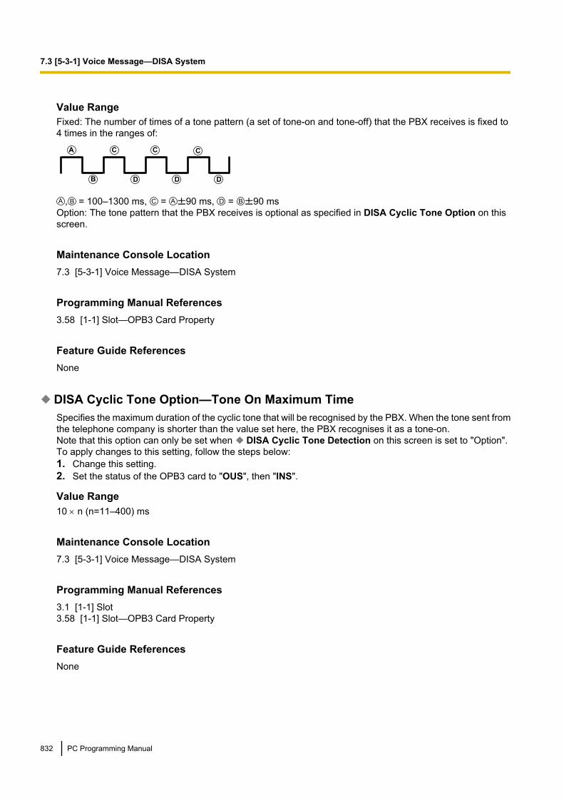
Value RangeFixed: The number of times of a tone pattern (a set of tone-on and tone-off) that the PBX receives is fixed to4 times in the ranges of:
A
B
C
D
C C
D D
, = 100–1300 ms, = 90 ms, = 90 msOption: The tone pattern that the PBX receives is optional as specified in DISA Cyclic Tone Option on thisscreen.
Maintenance Console Location7.3 [5-3-1] Voice Message—DISA System
Programming Manual References3.58 [1-1] Slot—OPB3 Card Property
Feature Guide ReferencesNone
DISA Cyclic Tone Option—Tone On Maximum TimeSpecifies the maximum duration of the cyclic tone that will be recognised by the PBX. When the tone sent fromthe telephone company is shorter than the value set here, the PBX recognises it as a tone-on.Note that this option can only be set when DISA Cyclic Tone Detection on this screen is set to "Option".To apply changes to this setting, follow the steps below:1. Change this setting.2. Set the status of the OPB3 card to "OUS", then "INS".
Value Range10 ´ n (n=11–400) ms
Maintenance Console Location7.3 [5-3-1] Voice Message—DISA System
Programming Manual References3.1 [1-1] Slot3.58 [1-1] Slot—OPB3 Card Property
Feature Guide ReferencesNone
832 PC Programming Manual
7.3 [5-3-1] Voice Message—DISA System

DISA Cyclic Tone Option—Tone Off Maximum TimeSpecifies the maximum time that the PBX waits for a cyclic tone to be sent from the telephone company beforerecognising it as a tone-off. When no tone is detected within the time set here, the PBX recognises it as atone-off.Note that this option can only be set when DISA Cyclic Tone Detection on this screen is set to "Option".To apply changes to this setting, follow the steps below:1. Change this setting.2. Set the status of the OPB3 card to "OUS", then "INS"
Value Range10 ´ n (n=11–400) ms
Maintenance Console Location7.3 [5-3-1] Voice Message—DISA System
Programming Manual References3.1 [1-1] Slot3.58 [1-1] Slot—OPB3 Card Property
Feature Guide ReferencesNone
DISA Cyclic Tone Option—Repeating Times of ON/OFF for DetectionSpecifies the number of times the tone pattern (a set of tone-on and tone-off) must be received to establishreception of the cyclic tone. This determines the end of call.Note that this option can only be set when DISA Cyclic Tone Detection on this screen is set to "Option".
Value Range3–16
Maintenance Console Location7.3 [5-3-1] Voice Message—DISA System
Programming Manual ReferencesNone
Feature Guide ReferencesNone
Timed Reminder Message—Day, Lunch, Break, NightSpecifies the prerecorded message to play when a Timed Reminder call is answered in each time mode.
Value RangeNone, 1–64
PC Programming Manual 833
7.3 [5-3-1] Voice Message—DISA System

Maintenance Console Location7.3 [5-3-1] Voice Message—DISA System
Programming Manual References7.4 [5-3-2] Voice Message—DISA Message
Feature Guide References1.28.4 Timed Reminder
Recording ModeSpecifies the sound quality of messages recorded on the ESVM card when using it as an MSG card. Increasingthe recording quality reduces the total length of recording time available on the card.To apply changes to this setting, follow the steps below:1. Change this setting.2. Set the status of the OPB3 card to "OUS", then "INS".
Value RangeLow: About 120 minutes of messages can be recorded per card.Middle: About 60 minutes of messages can be recorded per card.High: About 20 minutes of messages can be recorded per card.
Maintenance Console Location7.3 [5-3-1] Voice Message—DISA System
Programming Manual ReferencesNone
Feature Guide References1.17.7 Built-in Simplified Voice Message (SVM)
834 PC Programming Manual
7.3 [5-3-1] Voice Message—DISA System
7.4 [5-3-2] Voice Message—DISA MessageOutgoing messages (OGM) for DISA calls can be specified. A maximum of 64 OGMs can be programmed.To view a list of all programmed extension numbers and types, click Extension List View (see 2.5.8 Tool—Extension List View). To assign AA destinations easily, click Extension No. Setting (see 2.1.6 ExtensionNumber Setting).
Floating Extension NumberSpecifies the floating extension number of the OGM.
Value RangeMax. 5 digits (consisting of 0–9)
Maintenance Console Location7.4 [5-3-2] Voice Message—DISA Message
Programming Manual ReferencesNone
Feature Guide References1.17.5 Outgoing Message (OGM)1.17.6 Direct Inward System Access (DISA)
NameSpecifies the name of the OGM.
Value RangeMax. 20 characters
Maintenance Console Location7.4 [5-3-2] Voice Message—DISA Message
Programming Manual ReferencesNone
Feature Guide References1.17.5 Outgoing Message (OGM)1.17.6 Direct Inward System Access (DISA)
1 Digit AA Destination (Extension Number)—Dial 0–9Specifies the destination for each DISA Automated Attendant (AA) number. After listening to an OGM, thecaller can be directed to the destination by dialling a 1-digit DISA AA number.
PC Programming Manual 835
7.4 [5-3-2] Voice Message—DISA Message

Value RangeMax. 5 digits (consisting of 0–9, *, and #)
Maintenance Console Location7.4 [5-3-2] Voice Message—DISA Message
Programming Manual ReferencesNone
Feature Guide References1.17.5 Outgoing Message (OGM)1.17.6 Direct Inward System Access (DISA)
Busy / DND Message No.Selects the OGM to be played for the caller when the destination party is busy or sets DND.
Value RangeNone, 1–64
Maintenance Console Location7.4 [5-3-2] Voice Message—DISA Message
Programming Manual References7.3 [5-3-1] Voice Message—DISA System
Feature Guide References1.17.6 Direct Inward System Access (DISA)
836 PC Programming Manual
7.4 [5-3-2] Voice Message—DISA Message
7.5 [5-3-3] Voice Message—SVMSettings related to Built-in Simplified Voice Message feature can be specified. This feature can be accessedvia the IPCMPR/IPCEMPR card or ESVM card.
SVM Card No.1, 2—Slot NumberIndicates the slot position (reference only).
Value RangeSlot number
Maintenance Console Location7.5 [5-3-3] Voice Message—SVM
Programming Manual References3.1 [1-1] Slot
Feature Guide References1.17.7 Built-in Simplified Voice Message (SVM)
SVM Card No.1, 2—Floating Extension NumberSpecifies the floating extension number used to access the SVM feature.
Value RangeMax. 5 digits (consisting of 0–9)
Maintenance Console Location7.5 [5-3-3] Voice Message—SVM
Programming Manual ReferencesNone
Feature Guide References1.17.7 Built-in Simplified Voice Message (SVM)
SVM Card No.1, 2—Card NameSpecifies the name of the card, for programming reference.
Value RangeMax. 20 characters
PC Programming Manual 837
7.5 [5-3-3] Voice Message—SVM

Maintenance Console Location7.5 [5-3-3] Voice Message—SVM
Programming Manual ReferencesNone
Feature Guide References1.17.7 Built-in Simplified Voice Message (SVM)
Recording ModeSpecifies the sound quality of messages recorded by the SVM feature. Increasing the recording quality reducesthe total length of recording time available with this feature.
Value RangeLow: About 120 minutes of messages can be recorded.Middle: About 60 minutes of messages can be recorded.High: About 40 minutes (IPCMPR/IPCEMPR)/20 minutes (ESVM) of messages can be recorded.
Maintenance Console Location7.5 [5-3-3] Voice Message—SVM
Programming Manual References6.9 [4-1-7] Wired Extension—Simplified Voice Message6.16 [4-2-5] Portable Station—Simplified Voice Message
Feature Guide References1.17.7 Built-in Simplified Voice Message (SVM)
Remote AccessSelects whether the Walking COS feature can be used while listening to a greeting message from the SVMfeature. Using Walking COS, a user can access his or her message box remotely.
Value RangeDisable, Enable
Maintenance Console Location7.5 [5-3-3] Voice Message—SVM
Programming Manual References6.9 [4-1-7] Wired Extension—Simplified Voice Message6.16 [4-2-5] Portable Station—Simplified Voice Message
838 PC Programming Manual
7.5 [5-3-3] Voice Message—SVM

Feature Guide References1.17.7 Built-in Simplified Voice Message (SVM)
SVM Cyclic Tone DetectionSelects the cyclic tone detection mode. Cyclic tone detection is used to determine the end of a call when anextension user records a greeting message or callers leave voice messages in a message box.To apply changes to this setting, follow the steps below:1. Change this setting.2. Set the status of the IPCMPR/IPCEMPR card or OPB3 card to "OUS", then "INS". See 3.5 [1-1] Slot—
OPB3 Card Property or 3.58 [1-1] Slot—OPB3 Card Property.
Value RangeFixed: The number of times of a tone pattern (a set of tone-on and tone-off) that the PBX receives is fixed to4 times in the ranges of:
A
B
C
D
C C
D D
, = 100–1300 ms, = 90 ms, = 90 msOption: The tone pattern that the PBX receives is optional as specified in SVM Cyclic Tone Option on thisscreen.
Maintenance Console Location7.5 [5-3-3] Voice Message—SVM
Programming Manual References3.1 [1-1] Slot
Feature Guide References1.17.7 Built-in Simplified Voice Message (SVM)
SVM Cyclic Tone Option—Tone On Maximum TimeSpecifies the maximum duration of the cyclic tone that will be recognised by the PBX. When the tone sent fromthe telephone company is shorter than the value set here, the PBX recognises it as a tone-on.Note that this option can only be set when SVM Cyclic Tone Detection on this screen is set to "Option".To apply changes to this setting, follow the steps below:1. Change this setting.2. Set the status of the IPCMPR/IPCEMPR card or OPB3 card to "OUS", then "INS". See 3.5 [1-1] Slot—
OPB3 Card Property or 3.58 [1-1] Slot—OPB3 Card Property.
Value Range20 ´ n (n=6–200) ms
Maintenance Console Location7.5 [5-3-3] Voice Message—SVM
PC Programming Manual 839
7.5 [5-3-3] Voice Message—SVM

Programming Manual References3.1 [1-1] Slot
Feature Guide References1.17.7 Built-in Simplified Voice Message (SVM)
SVM Cyclic Tone Option—Tone Off Maximum TimeSpecifies the maximum time that the PBX waits for a cyclic tone to be sent from the telephone company beforerecognising it as a tone-off. When no tone is detected within the time set here, the PBX recognises it as atone-off.Note that this option can only be set when SVM Cyclic Tone Detection on this screen is set to "Option".To apply changes to this setting, follow the steps below:1. Change this setting.2. Set the status of the IPCMPR/IPCEMPR card or OPB3 card to "OUS", then "INS". See 3.5 [1-1] Slot—
OPB3 Card Property or 3.58 [1-1] Slot—OPB3 Card Property.
Value Range20 ´ n (n=6–200) ms
Maintenance Console Location7.5 [5-3-3] Voice Message—SVM
Programming Manual References3.1 [1-1] Slot
Feature Guide References1.17.7 Built-in Simplified Voice Message (SVM)
SVM Cyclic Tone Option—Repeating Times of ON/OFF for DetectionSpecifies the number of times the tone pattern (a set of tone-on and tone-off) must be received to establishreception of the cyclic tone. This determines the end of call.Note that this option can only be set when SVM Cyclic Tone Detection on this screen is set to "Option".
Value Range3–16
Maintenance Console Location7.5 [5-3-3] Voice Message—SVM
Programming Manual ReferencesNone
840 PC Programming Manual
7.5 [5-3-3] Voice Message—SVM

Feature Guide References1.17.7 Built-in Simplified Voice Message (SVM)
PC Programming Manual 841
7.5 [5-3-3] Voice Message—SVM
7.6 [5-4] External RelaySettings related to external relays can be programmed.
External Relay No.Indicates the number of the external relay (reference only).
Value RangeFor KX-TDE100/KX-TDE200:1–16
For KX-TDE600:1–64
Maintenance Console Location7.6 [5-4] External Relay
Programming Manual ReferencesNone
Feature Guide References1.17.9 External Relay Control
Physical Location—Shelf (KX-TDE600 only)Indicates the shelf position (reference only).
Value RangeShelf number
Maintenance Console Location7.6 [5-4] External Relay
Programming Manual ReferencesNone
Feature Guide References1.17.9 External Relay Control
Physical Location—SlotIndicates the slot position (reference only).
842 PC Programming Manual
7.6 [5-4] External Relay

Value RangeSlot and sub-slot number
Maintenance Console Location7.6 [5-4] External Relay
Programming Manual ReferencesNone
Feature Guide References1.17.9 External Relay Control
Physical Location—PortIndicates the port number (reference only).
Value RangePort number
Maintenance Console Location7.6 [5-4] External Relay
Programming Manual ReferencesNone
Feature Guide References1.17.9 External Relay Control
NameSpecifies the relay name.
Value RangeMax. 20 characters
Maintenance Console Location7.6 [5-4] External Relay
Programming Manual ReferencesNone
PC Programming Manual 843
7.6 [5-4] External Relay

Feature Guide References1.17.9 External Relay Control
Relay Activate TimeSpecifies the length of time that the relay stays on when activated.
Value Range1–7 s
Maintenance Console Location7.6 [5-4] External Relay
Programming Manual ReferencesNone
Feature Guide References1.17.9 External Relay Control
COS NumberSpecifies the Class of Service (COS) number. COS programming determines the extensions that are able toactivate relays.
Value Range1–64
Maintenance Console Location7.6 [5-4] External Relay
Programming Manual References4.12 [2-7-1] Class of Service—COS Settings—Optional Device & Other Extensions— External Relay Access
Feature Guide References1.1.2.2 Internal Call Block1.17.9 External Relay Control
844 PC Programming Manual
7.6 [5-4] External Relay

7.7 [5-5] External SensorSettings related to external sensors can be programmed.To assign destinations for sensor calls easily, click Destination Setting (see 2.1.6 Extension NumberSetting).
External Sensor No.Indicates the number of the external sensor (reference only).
Value RangeFor KX-TDE100/KX-TDE200:1–16
For KX-TDE600:1–64
Maintenance Console Location7.7 [5-5] External Sensor
Programming Manual ReferencesNone
Feature Guide References1.17.8 External Sensor
Physical Location—Shelf (KX-TDE600 only)Indicates the shelf position (reference only).
Value RangeShelf number
Maintenance Console Location7.7 [5-5] External Sensor
Programming Manual ReferencesNone
Feature Guide References1.17.8 External Sensor
Physical Location—SlotIndicates the slot position (reference only).
PC Programming Manual 845
7.7 [5-5] External Sensor
Value RangeSlot and sub-slot number
Maintenance Console Location7.7 [5-5] External Sensor
Programming Manual ReferencesNone
Feature Guide References1.17.8 External Sensor
Physical Location—PortIndicates the port number (reference only).
Value RangePort number
Maintenance Console Location7.7 [5-5] External Sensor
Programming Manual ReferencesNone
Feature Guide References1.17.8 External Sensor
NameSpecifies the sensor name.
Value RangeMax. 20 characters
Maintenance Console Location7.7 [5-5] External Sensor
Programming Manual ReferencesNone
846 PC Programming Manual
7.7 [5-5] External Sensor

Feature Guide References1.17.8 External Sensor
Destination—Day, Lunch, Break, NightSpecifies the destination number of sensor calls for each port in each time mode.
Value RangeMax. 32 digits (consisting of 0–9, *, #, [ ] [Secret], and P [Pause])
Maintenance Console Location7.7 [5-5] External Sensor
Programming Manual ReferencesNone
Feature Guide References1.17.8 External Sensor
Tenant No.Specifies the tenant to which the sensor belongs, to determine the Time Table for the sensor. (The tenantnumber corresponds to the Time Table number.)
Value RangeFor KX-TDE100/KX-TDE200:1–8
For KX-TDE600:1–32
Maintenance Console Location7.7 [5-5] External Sensor
Programming Manual References4.6 [2-4] Week Table
Feature Guide References1.17.8 External Sensor2.2.3 Tenant Service
PC Programming Manual 847
7.7 [5-5] External Sensor

848 PC Programming Manual
7.7 [5-5] External Sensor

Section 8
[6] Feature
PC Programming Manual 849
8.1 [6-1] System Speed DialThe System Speed Dialling Table is used to store frequently dialled numbers as well as callers who should beautomatically routed to certain extensions when they call (Calling Line Identification [CLI] distribution). TheSystem Speed Dialling Table is available for all extension users when making or receiving a call.A maximum of 1000 System Speed Dialling numbers (e.g., telephone numbers, feature numbers) can beprogrammed with other related parameters. 100 numbers are displayed at a time. To display other sets ofnumbers, click the applicable tab.
MemorySelects the System Speed Dialling Table to be programmed. Whether a tenant uses the basic System SpeedDialling Table or the additional table depends on the setting of System Speed Dial in 8.6 [6-6] Tenant.
Value RangeFor KX-TDE100/KX-TDE200:Basic Memory: the standard tableExpansion for Tenant 1–8: additional tables
For KX-TDE600:Basic Memory: the standard tableExpansion for Tenant 1–32: additional tables
Maintenance Console Location8.1 [6-1] System Speed Dial
Programming Manual References8.6 [6-6] Tenant— System Speed Dial
Feature Guide References1.6.1.5 Speed Dialling—Personal/System1.18.1 Caller ID2.2.3 Tenant Service
NameSpecifies a name for the System Speed Dialling number.
Value RangeMax. 20 characters
Maintenance Console Location8.1 [6-1] System Speed Dial
Programming Manual ReferencesNone
850 PC Programming Manual
8.1 [6-1] System Speed Dial

Feature Guide References1.6.1.5 Speed Dialling—Personal/System1.18.1 Caller ID
CO Line Access Number + Telephone NumberSpecifies the telephone number (including the Trunk Access number) or feature number assigned to theSystem Speed Dialling number.
Value RangeMax. 32 digits (consisting of 0–9, *, #, T [Transfer], [ ] [Secret], P [Pause], and F [Flash])
Maintenance Console Location8.1 [6-1] System Speed Dial
Programming Manual ReferencesNone
Feature Guide References1.6.1.5 Speed Dialling—Personal/System1.18.1 Caller ID
CLI DestinationSpecifies the CLI destination (extension) to which incoming calls from the programmed telephone number arerouted. If a Caller ID Modification Table is being used, the modified number must match the telephone numberabove (CO Line Access Number + Telephone Number) in order for the call to be routed correctly.
Value RangeMax. 5 digits (consisting of 0–9)
Maintenance Console Location8.1 [6-1] System Speed Dial
Programming Manual References12.2 [10-2] DIL Table & Port Settings—CLI for DIL— CLI Ring for DIL—Day, Lunch, Break, Night12.3 [10-3] DDI / DID Table— CLI Ring for DDI/DID—Day, Lunch, Break, Night
Feature Guide References1.1.1.5 Calling Line Identification (CLI) Distribution1.18.1 Caller ID
PC Programming Manual 851
8.1 [6-1] System Speed Dial

8.2 [6-2] Hotel & ChargeVarious settings related to the hospitality features of the PBX can be set.
MainHotel Operator—Extension 1–4Specifies the numbers of the extensions designated as hotel operators.
Value Range100–699
Maintenance Console Location8.2 [6-2] Hotel & Charge
Programming Manual ReferencesNone
Feature Guide References1.27.1 Hospitality Features—SUMMARY1.27.2 Room Status Control
SMDR for External Hotel Application 1—Room Status ControlSelects whether check-in and check-out data is output on SMDR.
Value RangeNo Print, Print
Maintenance Console Location8.2 [6-2] Hotel & Charge
Programming Manual References13.1 [11-1] Main
Feature Guide References1.26.1.1 Station Message Detail Recording (SMDR)1.27.2 Room Status Control
SMDR for External Hotel Application 1—Timed Reminder (Wake-up Call)Selects whether Timed Reminder data is output on SMDR.
Value RangeNo Print, Print
852 PC Programming Manual
8.2 [6-2] Hotel & Charge
Maintenance Console Location8.2 [6-2] Hotel & Charge
Programming Manual References13.1 [11-1] Main
Feature Guide References1.26.1.1 Station Message Detail Recording (SMDR)1.28.4 Timed Reminder
SMDR for External Hotel Application 2—Printing Message 1–8Specifies the text of the message output on SMDR when this Printing Message is selected from an extension.The "%" character can be used in a message, and requires a number to be entered in its place when themessage is selected from an extension. This character can be used a maximum of seven times in a PrintingMessage.
Value RangeMax. 16 characters
Maintenance Console Location8.2 [6-2] Hotel & Charge
Programming Manual References13.1 [11-1] Main
Feature Guide References1.26.1.1 Station Message Detail Recording (SMDR)1.26.2 Printing Message
BillCheckout Billing—Billing for GuestActivates call billing features for the PBX.
Value RangeOFF, ON
Maintenance Console Location8.2 [6-2] Hotel & Charge
Programming Manual References3.4 [1-1] Slot—Card Property - IPCMPR
PC Programming Manual 853
8.2 [6-2] Hotel & Charge

Feature Guide References1.27.3 Call Billing for Guest Room
Checkout Billing—LCD for "Telephone"Specifies the name of charge item 1 as shown on the display of the hotel operator extension when enteringroom charges.
Value RangeMax. 12 characters
Maintenance Console Location8.2 [6-2] Hotel & Charge
Programming Manual ReferencesNone
Feature Guide References1.27.3 Call Billing for Guest Room
Checkout Billing—LCD for "Minibar"Specifies the name of charge item 2 as shown on the display of the hotel operator extension when enteringroom charges.
Value RangeMax. 12 characters
Maintenance Console Location8.2 [6-2] Hotel & Charge
Programming Manual ReferencesNone
Feature Guide References1.27.3 Call Billing for Guest Room
Checkout Billing—LCD for "Others"Specifies the name of charge item 3 as shown on the display of the hotel operator extension when enteringroom charges.
Value RangeMax. 12 characters
854 PC Programming Manual
8.2 [6-2] Hotel & Charge

Maintenance Console Location8.2 [6-2] Hotel & Charge
Programming Manual ReferencesNone
Feature Guide References1.27.3 Call Billing for Guest Room
Checkout Billing—Bill (SMDR) for "Telephone"Specifies the name of charge item 1 as printed on the guest bill.
Value RangeMax. 12 characters
Maintenance Console Location8.2 [6-2] Hotel & Charge
Programming Manual ReferencesNone
Feature Guide References1.27.3 Call Billing for Guest Room
Checkout Billing—Bill (SMDR) for "Minibar"Specifies the name of charge item 2 as printed on the guest bill.
Value RangeMax. 12 characters
Maintenance Console Location8.2 [6-2] Hotel & Charge
Programming Manual ReferencesNone
Feature Guide References1.27.3 Call Billing for Guest Room
PC Programming Manual 855
8.2 [6-2] Hotel & Charge
Checkout Billing—Bill (SMDR) for "Others"Specifies the name of charge item 3 as printed on the guest bill.
Value RangeMax. 12 characters
Maintenance Console Location8.2 [6-2] Hotel & Charge
Programming Manual ReferencesNone
Feature Guide References1.27.3 Call Billing for Guest Room
SMDR for External Hotel Application—Language for Bill (SMDR)Specifies the language used for standard items shown on guest bills printed out using the Call Billing feature.
Value RangeLanguage 1–Language 5
Maintenance Console Location8.2 [6-2] Hotel & Charge
Programming Manual ReferencesNone
Feature Guide References1.27.3 Call Billing for Guest Room
SMDR for External Hotel Application—Header 1–3Specifies the text printed at the top of the guest bill.
Value RangeMax. 80 characters
Maintenance Console Location8.2 [6-2] Hotel & Charge
Programming Manual ReferencesNone
856 PC Programming Manual
8.2 [6-2] Hotel & Charge

Feature Guide References1.27.3 Call Billing for Guest Room
SMDR for External Hotel Application—Footer 1–3Specifies the text printed at the bottom of the guest bill.
Value RangeMax. 80 characters
Maintenance Console Location8.2 [6-2] Hotel & Charge
Programming Manual ReferencesNone
Feature Guide References1.27.3 Call Billing for Guest Room
ChargeMargin & Tax—Margin Rate for "Telephone" (%)Specifies the percentage margin to be added to telephone charges displayed on the guest bill.
Value Range0.00–99.99 %
Maintenance Console Location8.2 [6-2] Hotel & Charge
Programming Manual ReferencesNone
Feature Guide References1.26.3 Call Charge Services1.27.3 Call Billing for Guest Room
Margin & Tax—Tax Rate for "Telephone" (%)Specifies the percentage tax rate to be used when calculating guest telephone charges.
Value Range0.00–99.99 %
PC Programming Manual 857
8.2 [6-2] Hotel & Charge

Maintenance Console Location8.2 [6-2] Hotel & Charge
Programming Manual ReferencesNone
Feature Guide References1.27.3 Call Billing for Guest Room
Margin & Tax—Tax Rate for "Minibar" (%)Specifies the percentage tax rate to be used when calculating guest charges for charge item 2.
Value Range0.00–99.99 %
Maintenance Console Location8.2 [6-2] Hotel & Charge
Programming Manual ReferencesNone
Feature Guide References1.27.3 Call Billing for Guest Room
Margin & Tax—Tax Rate for "Others" (%)Specifies the percentage tax rate to be used when calculating guest charges for charge item 3.
Value Range0.00–99.99 %
Maintenance Console Location8.2 [6-2] Hotel & Charge
Programming Manual ReferencesNone
Feature Guide References1.27.3 Call Billing for Guest Room
858 PC Programming Manual
8.2 [6-2] Hotel & Charge

Charge Options—Digits After Decimal PointSpecifies the number of digits to display after the decimal point for the currency in use.
Value Range0–6
Maintenance Console Location8.2 [6-2] Hotel & Charge
Programming Manual References6.1 [4-1-1] Wired Extension—Extension Settings—Option 3— Charge Limit6.10 [4-2-1] Portable Station—Extension Settings—Option 3— Charge Limit8.3 [6-3] Verification Code— Budget Management
Feature Guide References1.20.4 Display Information1.26.3 Call Charge Services1.27.3 Call Billing for Guest Room
Charge Options—CurrencySpecifies the currency characters shown on the display of the extension and the SMDR.
Value RangeMax. 3 characters
Maintenance Console Location8.2 [6-2] Hotel & Charge
Programming Manual References6.1 [4-1-1] Wired Extension—Extension Settings—Option 3— Charge Limit6.10 [4-2-1] Portable Station—Extension Settings—Option 3— Charge Limit8.3 [6-3] Verification Code— Budget Management
Feature Guide References1.20.4 Display Information1.26.1.1 Station Message Detail Recording (SMDR)1.26.3 Call Charge Services1.27.3 Call Billing for Guest Room
Charge Options—Currency Display PositionSpecifies whether the currency characters are displayed before or after the call charge.
Value RangeHead, Tail
PC Programming Manual 859
8.2 [6-2] Hotel & Charge

Maintenance Console Location8.2 [6-2] Hotel & Charge
Programming Manual References6.1 [4-1-1] Wired Extension—Extension Settings—Option 3— Charge Limit6.10 [4-2-1] Portable Station—Extension Settings—Option 3— Charge Limit8.3 [6-3] Verification Code— Budget Management
Feature Guide References1.26.3 Call Charge Services
Charge Options—Action at Charge LimitSelects what happens when the amount of the call charge reaches the preprogrammed limit during aconversation.
Value RangeAlarm: Only a warning tone is heard.Alarm + Disconnect: A warning tone is heard, and then the call is disconnected.
Maintenance Console Location8.2 [6-2] Hotel & Charge
Programming Manual References6.1 [4-1-1] Wired Extension—Extension Settings—Option 3— Charge Limit6.10 [4-2-1] Portable Station—Extension Settings—Option 3— Charge Limit
Feature Guide References1.9.2 Budget Management
Charge Options—Meter Start on Answer DetectionEnables the PBX to start counting the call charge when the answer signal from the telephone company isdetected.
Value RangeDisable, Enable
Maintenance Console Location8.2 [6-2] Hotel & Charge
Programming Manual References6.1 [4-1-1] Wired Extension—Extension Settings—Option 3— Charge Limit6.10 [4-2-1] Portable Station—Extension Settings—Option 3— Charge Limit
860 PC Programming Manual
8.2 [6-2] Hotel & Charge

Feature Guide References1.26.3 Call Charge Services
PC Programming Manual 861
8.2 [6-2] Hotel & Charge

8.3 [6-3] Verification CodeA verification code is used to override the Toll Restriction (TRS)/Call Barring (Barring) of the extension in useto make a certain trunk call, or to identify the call for accounting and billing purposes.A maximum of 1000 verification codes can be programmed with other related parameters. 100 codes aredisplayed at a time. To display other sets of codes, click the applicable tab.
Verification CodeSpecifies the verification code.
Value RangeMax. 4 digits (consisting of 0–9, *, and #)
Maintenance Console Location8.3 [6-3] Verification Code
Programming Manual ReferencesNone
Feature Guide References1.9.6 Verification Code Entry
User NameSpecifies the user name assigned to the verification code.
Value RangeMax. 20 characters
Maintenance Console Location8.3 [6-3] Verification Code
Programming Manual ReferencesNone
Feature Guide References1.9.6 Verification Code Entry
Verification Code PINSpecifies the PIN to be entered when making a trunk call with the verification code.
CAUTIONThere is a risk that fraudulent telephone calls will be made if a third party discovers a personal identificationnumber (PIN) (verification code PIN or extension PIN) of the PBX.
862 PC Programming Manual
8.3 [6-3] Verification Code

The cost of such calls will be billed to the owner/renter of the PBX.To protect the PBX from this kind of fraudulent use, we strongly recommend:a. Keeping PINs secret.b. Selecting complex, random PINs that cannot be easily guessed.c. Changing PINs frequently.
Value RangeMax. 10 digits (consisting of 0–9)
Maintenance Console Location8.3 [6-3] Verification Code
Programming Manual ReferencesNone
Feature Guide References1.9.6 Verification Code Entry
COS NumberSpecifies the COS that applies when making a trunk call with the verification code.
Value Range1–64
Maintenance Console Location8.3 [6-3] Verification Code
Programming Manual References4.12 [2-7-1] Class of Service—COS Settings
Feature Guide References1.9.6 Verification Code Entry2.2.1 Class of Service (COS)
Itemised Billing Code for ARSSpecifies the itemised billing code used by the ARS feature for identifying calls made with a verification codefor accounting and billing purposes.
Value RangeMax. 10 digits (consisting of 0–9, *, and #)
Maintenance Console Location8.3 [6-3] Verification Code
PC Programming Manual 863
8.3 [6-3] Verification Code
Programming Manual References10.6 [8-5] Carrier
Feature Guide References1.10.1 Automatic Route Selection (ARS)
Budget ManagementSpecifies the limit of the call charge that will be counted on the verification code.The number of decimal places that can be specified here depends on the value set in Charge Options—Digits After Decimal Point in 8.2 [6-2] Hotel & Charge.
Value Range0–9999999
Maintenance Console Location8.3 [6-3] Verification Code
Programming Manual ReferencesNone
Feature Guide References1.9.2 Budget Management
864 PC Programming Manual
8.3 [6-3] Verification Code
8.4 [6-4] Second Dial ToneA programmed Pause time can be inserted automatically between the Second Dial Tone Waiting code andthe following digits. When a programmed Second Dial Tone Waiting code is dialled after seizing a trunk, apreprogrammed number of pauses are inserted after the code.A maximum of 100 Second Dial Tone Waiting codes can be programmed. 20 codes are displayed at a time.To display other sets of codes, click the applicable tab.
Second Dial Tone Waiting CodeSpecifies the Second Dial Tone Waiting code.
Value RangeMax. 4 digits (consisting of 0–9, *, and #)
Maintenance Console Location8.4 [6-4] Second Dial Tone
Programming Manual ReferencesNone
Feature Guide References1.5.4.7 Pause Insertion
Pause Repeating CounterSpecifies the number of pauses to be inserted when waiting for the second dial tone.
Value Range0–20
Maintenance Console Location8.4 [6-4] Second Dial Tone
Programming Manual ReferencesNone
Feature Guide References1.5.4.7 Pause Insertion
PC Programming Manual 865
8.4 [6-4] Second Dial Tone
8.5 [6-5] Absent MessageWhen a display PT user calls an extension, a message is shown on the caller’s telephone display describingthe reason for absence. A maximum of 8 Absent Messages can be programmed, and any extension user canselect one of them.
Absent MessageSpecifies the message for display.
Value RangeMax. 16 characters
Maintenance Console Location8.5 [6-5] Absent Message
Programming Manual ReferencesNone
Feature Guide References1.19.2 Absent Message
866 PC Programming Manual
8.5 [6-5] Absent Message

8.6 [6-6] TenantA maximum of 8 (KX-TDE100/KX-TDE200)/32 (KX-TDE600) tenants can share the PBX. Each tenant iscomposed of specified extension user groups. The PBX offers each tenant its own Time Table and systemresources.To assign extensions as operators easily, click Extension No. Setting (see 2.1.6 Extension NumberSetting).
Music On HoldSpecifies the audio source to be used for Music on Hold.
Value RangeSame as System Setting, BGM, BGM2, BGM3, BGM4, BGM5, BGM6, BGM7, BGM8, Tone
Maintenance Console Location8.6 [6-6] Tenant
Programming Manual References4.4 [2-2] Operator & BGM
Feature Guide References1.13.4 Music on Hold2.2.3 Tenant Service
Operator (Extension Number)Specifies the extension number or the floating extension number of an incoming call distribution group to bedesignated as the tenant operator. When this parameter is left unspecified, the PBX operator serves as thetenant operator.
Value Range100–699
Maintenance Console Location8.6 [6-6] Tenant
Programming Manual References4.4 [2-2] Operator & BGM
Feature Guide References2.2.3 Tenant Service2.2.5 Operator Features
PC Programming Manual 867
8.6 [6-6] Tenant

ARS ModeSpecifies the ARS mode used when making a trunk call.
Value RangeOff: ARS is disabled.On for Local Access Operation: ARS operates when an extension user makes a call using any Idle Line Accessmethod.On for Any CO Access Operation: ARS operates when an extension user makes a call using any Trunk Accessmethod.Same as System Setting: The setting specified in ARS Mode in 10.1 [8-1] System Setting is applied.
Maintenance Console Location8.6 [6-6] Tenant
Programming Manual References10.1 [8-1] System Setting
Feature Guide References1.10.1 Automatic Route Selection (ARS)2.2.3 Tenant Service
System Speed DialSpecifies which system speed dialling table is used by the tenant.
Value RangeSame as System Setting: PBX common system speed dialling numbers are used.Tenant Exclusive: Individual tenant system speed dialling numbers are used.
Maintenance Console Location8.6 [6-6] Tenant
Programming Manual References8.1 [6-1] System Speed Dial
Feature Guide References1.6.1.5 Speed Dialling—Personal/System2.2.3 Tenant Service
868 PC Programming Manual
8.6 [6-6] Tenant

Section 9
[7] TRS
PC Programming Manual 869

9.1 [7-1] Denied CodeToll Restriction (TRS)/Call Barring (Barring) prohibits an extension from making certain trunk calls. Each timemode of every COS is assigned one of the seven TRS/Barring levels. TRS/Barring level 7 provides themaximum restriction (all trunk calls are prohibited) and level 1 provides the minimum (all trunk calls areallowed). TRS/Barring levels 2–6 are used to restrict calls according to the combination of Denied CodeTables here and Exception Code Tables in 9.2 [7-2] Exception Code. If the leading digits of the diallednumber are not found in the applicable Denied Code Tables, the call is made.A maximum of 100 denied codes can be programmed for each level. 20 codes are displayed at a time. Todisplay other sets of codes, click the applicable tab.
Denied Code Tables—Level 2–Level 6Specifies the leading digits of toll restricted numbers for each level.
Value RangeMax. 16 digits (consisting of 0-9, *, #, and X)
Maintenance Console Location9.1 [7-1] Denied Code
Programming Manual References4.12 [2-7-1] Class of Service—COS Settings—TRS— TRS Level—Day, Lunch, Break, Night9.2 [7-2] Exception Code
Feature Guide References1.9.1 Toll Restriction (TRS)/Call Barring (Barring)
870 PC Programming Manual
9.1 [7-1] Denied Code

9.2 [7-2] Exception CodeToll Restriction (TRS)/Call Barring (Barring) prohibits an extension from making certain trunk calls. Each timemode of every COS is assigned one of the seven TRS/Barring levels. TRS/Barring level 7 provides themaximum restriction (all trunk calls are prohibited) and level 1 provides the minimum (all trunk calls areallowed). TRS/Barring levels 2–6 are used to restrict calls according to the combination of Denied CodeTables in 9.1 [7-1] Denied Code and Exception Code Tables here. A call denied by the applicable DeniedCode Tables is checked against the applicable Exception Code Tables, and if a match is found, the call ismade.A maximum of 100 exception codes can be programmed for each level. 20 codes are displayed at a time. Todisplay other sets of codes, click the applicable tab.
Exception Code Tables—Level 2–Level 6Specifies the leading digits of the numbers to be exempted from toll restriction/call barring for each level.
Value RangeMax. 16 digits (consisting of 0-9, *, #, and X)
Maintenance Console Location9.2 [7-2] Exception Code
Programming Manual References4.12 [2-7-1] Class of Service—COS Settings—TRS— TRS Level—Day, Lunch, Break, Night9.1 [7-1] Denied Code
Feature Guide References1.9.1 Toll Restriction (TRS)/Call Barring (Barring)
PC Programming Manual 871
9.2 [7-2] Exception Code

9.3 [7-3] Special CarrierIf the PBX has access to multiple telephone companies, a Special Carrier Access Code is required each timea trunk call is made. By programming these Special Carrier Access Codes here, Toll Restriction (TRS)/CallBarring (Barring) can restrict or allow calls to be made by ignoring the codes and looking at the telephonenumber only. If a Special Carrier Access Code is found in the dialled number, TRS/Barring will look only at thefollowing digits.A maximum of 20 (with the KX-TDE100/KX-TDE200) or 100 (with the KX-TDE600) Special Carrier AccessCodes can be programmed. With the KX-TDE600, 20 codes are displayed at a time. To show other sets ofcodes, click the applicable tab.
Special Carrier Access CodeSpecifies a Special Carrier Access Code. Special Carrier Access Codes and Host PBX Access codes shouldbe unique.
Value RangeMax. 16 digits (consisting of 0–9, *, and #)
Maintenance Console Location9.3 [7-3] Special Carrier
Programming Manual ReferencesNone
Feature Guide References1.5.4.9 Special Carrier Access Code1.9.1 Toll Restriction (TRS)/Call Barring (Barring)
872 PC Programming Manual
9.3 [7-3] Special Carrier

9.4 [7-4] Emergency DialAny extension user can dial the programmed emergency numbers at any time after seizing a trunk. Therestrictions imposed on the extension, such as Toll Restriction (TRS)/Call Barring (Barring), Account Code—Forced mode, and Extension Dial Lock are disregarded.A maximum of 10 emergency numbers can be programmed.
Emergency NumberSpecifies the numbers used for making emergency calls. It is not necessary to start the emergency numberwith a Trunk Access number.
Value RangeMax. 32 digits (consisting of 0–9, *, #, T [Transfer], P [Pause], and F [Flash])
Maintenance Console Location9.4 [7-4] Emergency Dial
Programming Manual ReferencesNone
Feature Guide References1.5.4.2 Emergency Call
PC Programming Manual 873
9.4 [7-4] Emergency Dial
9.5 [7-5] MiscellaneousToll Restriction (TRS)/Call Barring (Barring) prohibits an extension from making certain trunk calls. Thefollowing optional settings can be programmed to activate a TRS/Barring check, override TRS/Barring, orswitch between TRS/Barring methods.
TRS Override by System Speed DiallingEnables an outgoing trunk call to override TRS/Barring when the call is made using System Speed Dialling.
Value RangeDisable, Enable
Maintenance Console Location9.5 [7-5] Miscellaneous
Programming Manual References8.1 [6-1] System Speed Dial
Feature Guide References1.9.1 Toll Restriction (TRS)/Call Barring (Barring)
TRS Check for Dial "* #"Enables a TRS/Barring check for the user-dialled " " and "#". This is useful in preventing unauthorised callswhich could possibly be made through certain telephone company exchanges.
Value RangeNo Check, Check
Maintenance Console Location9.5 [7-5] Miscellaneous
Programming Manual ReferencesNone
Feature Guide References1.9.1 Toll Restriction (TRS)/Call Barring (Barring)
Mode when Dial Time-out before TRS CheckSelects whether a trunk is disconnected if the TRS/Barring check has not been completed when the trunkInter-digit timer expires.
Value RangeDisconnect: The trunk is disconnected as soon as the timer expires.
874 PC Programming Manual
9.5 [7-5] Miscellaneous

Keep: The TRS/Barring check is performed when the timer expires.
Maintenance Console Location9.5 [7-5] Miscellaneous
Programming Manual References4.5 [2-3] Timers & Counters
Feature Guide References1.9.1 Toll Restriction (TRS)/Call Barring (Barring)
Dial Digits Limitation After Answering—Dial DigitsSpecifies a limit to be placed on the number of digits which can be dialled after an extension user receives atrunk call. If the number of dialled digits exceeds the programmed limit, the line will be disconnected.
Value RangeNone, 1–7
Maintenance Console Location9.5 [7-5] Miscellaneous
Programming Manual ReferencesNone
Feature Guide References1.9.1 Toll Restriction (TRS)/Call Barring (Barring)1.11.8 Trunk Call Limitation
TRS Check after EFAEnables TRS/Barring to check the digits dialled after External Feature Access (EFA) during a trunk call.
Value RangeDisable, Enable
Maintenance Console Location9.5 [7-5] Miscellaneous
Programming Manual ReferencesNone
PC Programming Manual 875
9.5 [7-5] Miscellaneous
Feature Guide References1.9.1 Toll Restriction (TRS)/Call Barring (Barring)1.11.7 External Feature Access (EFA)
TRS Table Mode for Level N (N=2_6)Selects the method of TRS/Barring to be used for restricting calls. The level of TRS/Barring is determined bythe telephone codes set in the Denied Code Tables and Exception Code Tables.
Value RangeDeny Table 2_N + Except Table N_6: The Denied Code Tables for the higher levels are applied to all levelsbelow it, and the Exception Code Tables for the lower levels are applied to all levels above it.Deny Table N + Except Table N: Each level has its own separate set of denied codes and exception codes,which are only applied to that level.
Maintenance Console Location9.5 [7-5] Miscellaneous
Programming Manual ReferencesNone
Feature Guide References1.9.1 Toll Restriction (TRS)/Call Barring (Barring)
876 PC Programming Manual
9.5 [7-5] Miscellaneous

Section 10
[8] ARS
PC Programming Manual 877

10.1 [8-1] System SettingAutomatic Route Selection (ARS) automatically selects the appropriate carrier at the time a trunk call is made,according to the programmed settings. The user-dialled number will be checked and modified in order toconnect it to the appropriate carrier.
ARS ModeSelects the condition to determine when to operate ARS.
Value RangeOff: ARS is disabled.On for Local Access Operation: ARS operates when an extension user makes a call using Idle Line Accessmethod.On for Any CO Access Operation: ARS operates when an extension user makes a call using Idle Line Access,Trunk Access, or S-CO Line Access method.
Maintenance Console Location10.1 [8-1] System Setting
Programming Manual ReferencesNone
Feature Guide References1.5.5.3 Trunk Access1.10.1 Automatic Route Selection (ARS)
Mode When Any Carrier is not programmed for the DialSelects what happens when the dialled number is not found in Leading Number in 10.2 [8-2] LeadingNumber.
Value RangeDisconnect: the line will be disconnected.Local Access: the dialled number will be handled by Idle Line Access method.
Maintenance Console Location10.1 [8-1] System Setting
Programming Manual ReferencesNone
Feature Guide References1.10.1 Automatic Route Selection (ARS)
878 PC Programming Manual
10.1 [8-1] System Setting

10.2 [8-2] Leading NumberSpecifies the area codes and/or telephone numbers as leading numbers that will be routed by the ARS feature.A maximum of 1000 different leading numbers can be programmed, and each leading number can select aRouting Plan Table number, which determines the ARS procedure.The additional (remaining) number of digits can also be specified for each leading number. The additional(remaining) number of digits must be specified only when "#", for example, is needed after the dialled number.The "#" will be added after the programmed number of digits of the user-dialled number (excluding the leadingnumber).100 leading numbers are displayed at a time. To display other sets of leading numbers, click the applicabletab.
Leading NumberSpecifies the leading number.
Value RangeMax. 16 digits (consisting of 0–9, *, #, and X)
Maintenance Console Location10.2 [8-2] Leading Number
Programming Manual ReferencesNone
Feature Guide References1.10.1 Automatic Route Selection (ARS)
Additional Number of DigitsSpecifies the additional (remaining) number of digits following each leading number.
Value Range0–15
Maintenance Console Location10.2 [8-2] Leading Number
Programming Manual ReferencesNone
Feature Guide References1.10.1 Automatic Route Selection (ARS)
PC Programming Manual 879
10.2 [8-2] Leading Number

Routing Plan NumberSpecifies the Routing Plan Table number used for each leading number.
Value RangeFor KX-TDE100/KX-TDE200:1–16
For KX-TDE600:1–48
Maintenance Console Location10.2 [8-2] Leading Number
Programming Manual ReferencesNone
Feature Guide References1.10.1 Automatic Route Selection (ARS)
880 PC Programming Manual
10.2 [8-2] Leading Number

10.3 [8-3] Routing Plan TimeThe start and end times of a maximum of 4 different time blocks are shown for each day of the week. Thereare 16 (with the KX-TDE100/KX-TDE200) or 48 (with the KX-TDE600) Routing Plan Tables, and each RoutingPlan Table can have its own time blocks. Select the desired Routing Plan Table number from the RoutingPlan list.• To adjust the currently displayed Routing Plan, click and drag the divisions between two time periods.• To programme the time blocks of the currently displayed Routing Plan, including adding or deleting time
blocks, click Time Setting.
PC Programming Manual 881
10.3 [8-3] Routing Plan Time

10.4 [8-3] Routing Plan Time—Time SettingThe start times of a maximum of 4 different time blocks can be programmed for each day of the week, for theselected Routing Plan. Each time block automatically ends when the subsequent block begins.
Time-A–D—SettingEnables the setting of the start time for each time block.
Value RangeDisable, Enable
Maintenance Console Location10.4 [8-3] Routing Plan Time—Time Setting
Programming Manual ReferencesNone
Feature Guide References1.10.1 Automatic Route Selection (ARS)
Time-A–D—Hour, MinuteSpecifies the start time for each time block.
Value Range00:00–23:59
Maintenance Console Location10.4 [8-3] Routing Plan Time—Time Setting
Programming Manual ReferencesNone
Feature Guide References1.10.1 Automatic Route Selection (ARS)
882 PC Programming Manual
10.4 [8-3] Routing Plan Time—Time Setting
10.5 [8-4] Routing Plan PriorityThe carrier priority (1 through 6) in a Routing Plan Table can be programmed for each time zone of each dayof the week. Select the desired Routing Plan Table number from the Routing Plan list. Select the desired dayof the week by clicking the applicable tab.
Time-A–Time-DSpecifies the carrier to be given priority for each time zone.
Value RangeFor KX-TDE100/KX-TDE200:None, 1–10
For KX-TDE600:None, 1–48
Maintenance Console Location10.5 [8-4] Routing Plan Priority
Programming Manual ReferencesNone
Feature Guide References1.10.1 Automatic Route Selection (ARS)
PC Programming Manual 883
10.5 [8-4] Routing Plan Priority

10.6 [8-5] CarrierCarrier
It is possible to specify how user-dialled numbers are modified for connecting to the appropriate carrier. Amaximum of 10 (with the KX-TDE100/KX-TDE200) or 48 (with the KX-TDE600) different carriers can beprogrammed to be used with the ARS feature.
Carrier NameSpecifies the carrier name.
Value RangeMax. 20 characters
Maintenance Console Location10.6 [8-5] Carrier
Programming Manual ReferencesNone
Feature Guide References1.10.1 Automatic Route Selection (ARS)
Removed Number of DigitsSpecifies the number of leading digits to remove from the user-dialled number.
Value Range0–15
Maintenance Console Location10.6 [8-5] Carrier
Programming Manual ReferencesNone
Feature Guide References1.10.1 Automatic Route Selection (ARS)
Modify CommandSpecifies the commands to modify the user-dialled number to access the carrier. For details of each command,see the Feature Guide.
884 PC Programming Manual
10.6 [8-5] Carrier

Value RangeMax. 16 characters (consisting of 0–9, *, #, C, P, A, G, I and H)
Maintenance Console Location10.6 [8-5] Carrier
Programming Manual ReferencesNone
Feature Guide References1.10.1 Automatic Route Selection (ARS)
Carrier Access CodeSpecifies the carrier access code. The carrier access code can be added to the user-dialled number byspecifying "C" in Modify Command on this screen.
Value RangeMax. 32 digits (consisting of 0–9, *, #, and P [Pause])
Maintenance Console Location10.6 [8-5] Carrier
Programming Manual ReferencesNone
Feature Guide References1.10.1 Automatic Route Selection (ARS)
TRG 01–TRG 64 (KX-TDE100/KX-TDE200), or TRG 01–TRG 96 (KX-TDE600)Selects the trunk groups that connect to the carrier.
TRG 01–TRG 64 (KX-TDE100/KX-TDE200), or TRG 01–TRG 96 (KX-TDE600)Enables each trunk group for each carrier. If a cell is highlighted in blue, that trunk group is enabled for usewith that carrier.
Value RangeOFF (white), ON (blue)
Maintenance Console Location10.6 [8-5] Carrier
PC Programming Manual 885
10.6 [8-5] Carrier

Programming Manual ReferencesNone
Feature Guide References1.10.1 Automatic Route Selection (ARS)
Authorisation Code for TenantSpecifies an Authorisation code for each tenant. The Authorisation codes can be added to the user-diallednumber by specifying "A" command in Modify Command on the Carrier tab.
Authorisation Code for Tenant—Tenant 1–Tenant 32Specifies the Authorisation code of each carrier for each tenant.
NoteFor the KX-TDE100/KX-TDE200, only up to 8 tenants are available.
Value RangeMax. 16 digits (consisting of 0–9, *, and #)
Maintenance Console Location10.6 [8-5] Carrier
Programming Manual ReferencesNone
Feature Guide References1.10.1 Automatic Route Selection (ARS)2.2.3 Tenant Service
886 PC Programming Manual
10.6 [8-5] Carrier
10.7 [8-6] Leading Number ExceptionSpecifies telephone numbers that will not be connected using the ARS feature. When the user-dialled numberincludes a leading number exception, the PBX sends the number to a trunk by the Idle Line Access method if
ARS Mode in 10.1 [8-1] System Setting is "on".A maximum of 200 different leading number exceptions can be programmed. 40 leading number exceptionentries are displayed on the screen at a time. To display other sets, click the applicable tab.
Leading Number ExceptionSpecifies the leading number exception.
Value RangeMax. 16 digits (consisting of 0–9, *, #, and X)
Maintenance Console Location10.7 [8-6] Leading Number Exception
Programming Manual ReferencesNone
Feature Guide References1.10.1 Automatic Route Selection (ARS)
PC Programming Manual 887
10.7 [8-6] Leading Number Exception

10.8 [8-7] Authorisation Code for TRGAn Authorisation code can be specified for each trunk group. The Authorisation codes entered here can beadded to user-dialled numbers by adding "G" to the Modify Command specified on the Carrier tab of screen10.6 [8-5] Carrier.8 trunk groups are displayed on the screen at a time. To display other groups, click the applicable tab.
Authorisation Code for Trunk Group—TRG 01–TRG 64 (KX-TDE100/KX-TDE200), or TRG 01–TRG 96 (KX-TDE600)
Specifies the Authorisation code of each carrier for each trunk group.
Value RangeMax. 10 digits (consisting of 0–9, *, and #)
Maintenance Console Location10.8 [8-7] Authorisation Code for TRG
Programming Manual References10.6 [8-5] Carrier—Carrier— Modify Command
Feature Guide References1.10.1 Automatic Route Selection (ARS)
888 PC Programming Manual
10.8 [8-7] Authorisation Code for TRG

Section 11
[9] Private Network
PC Programming Manual 889
11.1 [9-1] TIE TableA TIE line is a privately leased communication line between two or more PBXs, which provides cost effectivecommunications between company members at different locations.A maximum of 32 TIE Line Routing and Modification Tables can be programmed. It is necessary to makeunified tables with all PBXs at different locations in a TIE line network in order to identify the trunk route to beused when an extension makes or receives a TIE line call.There are two types of routing methods: the Extension Number Method, where all extensions in the networkare given a unique extension number; and the PBX Code Method, where each PBX is given a unique code,which is dialled before the extension number to call an extension at another PBX.Two priority sets (from a total of 8) are displayed at a time. To display other priority sets, click the applicabletab.Using a private network, up to 8 PBXs can share one VPS (centralised VM) connected to another PBX. ThisVPS can provide voice mail for extensions attached to any of the PBXs in the network.Only extension numbers of 4 digits or less, using the Extension Number Method, are supported.
Own PBX CodeSpecifies the PBX code of the local PBX, when using PBX Code Method numbering on a TIE line network. Ifthis cell is left empty, the Extension Number Method is used.
Value RangeMax. 7 digits (consisting of 0–9)
Maintenance Console Location11.1 [9-1] TIE Table
Programming Manual ReferencesNone
Feature Guide References1.30.1 TIE Line Service
Priority 1–Priority 8Leading NumberSpecifies the leading number for other PBX extension numbers or the PBX code of others in the TIE linenetwork.
Value RangeMax. 3 digits (consisting of 0–9, *, and #)
Maintenance Console Location11.1 [9-1] TIE Table
890 PC Programming Manual
11.1 [9-1] TIE Table
Programming Manual ReferencesNone
Feature Guide References1.30.1 TIE Line Service
Removed Number of DigitsSpecifies the number of leading digits of the dialled number to be removed for each priority.
Value Range0–15
Maintenance Console Location11.1 [9-1] TIE Table
Programming Manual ReferencesNone
Feature Guide References1.30.1 TIE Line Service
Added NumberSpecifies the number to be added to the dialled number in place of the removed digits for each priority.
Value RangeMax. 32 digits (consisting of 0–9, *, #, and P [Pause])
Maintenance Console Location11.1 [9-1] TIE Table
Programming Manual ReferencesNone
Feature Guide References1.30.1 TIE Line Service
Trunk GroupSpecifies the trunk group to be used for TIE line calls for each priority.
PC Programming Manual 891
11.1 [9-1] TIE Table

Value RangeFor KX-TDE100/KX-TDE200:None, 1–64
For KX-TDE600:None, 1–96
Maintenance Console Location11.1 [9-1] TIE Table
Programming Manual ReferencesNone
Feature Guide References1.30.1 TIE Line Service
Centralised VMLeading NumberSpecifies the leading number for other PBX extension numbers or the PBX code of other PBXs in the TIE linenetwork.
Value RangeMax. 3 digits (consisting of 0–9, *, and #)
Maintenance Console Location11.1 [9-1] TIE Table
Programming Manual ReferencesNone
Feature Guide References1.30.1 TIE Line Service
Enhanced QSIG Call Information (Optional SD Card Required)Enables Network Message Waiting information to be sent from the PBX to which the VPS is attached toextensions connected to other PBXs in the network.
Value RangeDisable, Enable
892 PC Programming Manual
11.1 [9-1] TIE Table

Maintenance Console Location11.1 [9-1] TIE Table
Programming Manual ReferencesNone
Feature Guide References1.30.5.2 Centralised Voice Mail
PC Programming Manual 893
11.1 [9-1] TIE Table

11.2 [9-2] Network Data TransmissionSettings related to the transmission of extension BLF (Busy Line Field) data or Message Waiting notificationsover a network of PBXs can be programmed.Extension BLF data is used to show the status of a monitored extension attached to another PBX on a NetworkDSS (NDSS) button. Network Message Waiting notifications are used for the Centralised VM feature, and aVPS can send notifications to extensions connected to any PBX in the network.
Network Data Transmission for Centralised Operator Feature—Network PBX IDSpecifies the Network ID of the PBX, for Network Direct Station Selection (NDSS). This parameter must beset in correspondence with the Network IDs assigned to other PBXs in the network.Network IDs 1-8 can only be assigned to one PBX each within a network. Assigning the same Network ID totwo PBXs will cause network data transmission problems.Changing this value in Interactive mode will automatically clear any NDSS Link Data.
Value Range0: The PBX retransmits BLF data sent by other PBXs.1: The PBX receives BLF data sent by other PBXs.2–8: The PBX transmits BLF data over the network.
Maintenance Console Location11.2 [9-2] Network Data Transmission
Programming Manual ReferencesNone
Feature Guide References1.30.5.1 Network Direct Station Selection (NDSS)
Network Data Transmission for Centralised Operator Feature—DataTransmission VoIP->ISDN
Selects whether to re-send BLF data received from a VoIP port through any ISDN ports that are set to transmitBLF data.
Value RangeDisable, Enable
Maintenance Console Location11.2 [9-2] Network Data Transmission
Programming Manual References3.33 [1-1] Slot—Port Property - BRI Port—ISDN CO— Networking Data Transfer3.35 [1-1] Slot—Port Property - PRI Port—CO Setting— Networking Data Transfer
894 PC Programming Manual
11.2 [9-2] Network Data Transmission

Feature Guide References1.30.5.1 Network Direct Station Selection (NDSS)
Network Data Transmission for Centralised Operator Feature—DataTransmission ISDN->VoIP
Selects whether to re-send BLF data received from an ISDN port through any VoIP ports that are set to transmitBLF data.
Value RangeDisable, Enable
Maintenance Console Location11.2 [9-2] Network Data Transmission
Programming Manual References11.3 [9-3] Network Operator (VoIP)— IP-GW Card Slot No. to notify BLF data to Network Operator
Feature Guide References1.30.5.1 Network Direct Station Selection (NDSS)
Network Data Transmission for Centralised Operator Feature—DataTransmission Counter
Specifies the maximum number of "hops", or transmissions between two PBXs, before a packet of BLF datais discarded.
Value Range1–63
Maintenance Console Location11.2 [9-2] Network Data Transmission
Programming Manual ReferencesNone
Feature Guide References1.30.5.1 Network Direct Station Selection (NDSS)
Network Data Transmission for Centralised Operator Feature—DataBroadcasting Interval Timer
Specifies the frequency of BLF data transmission. The PBX will send data over the network periodicallyaccording to the interval specified here.
PC Programming Manual 895
11.2 [9-2] Network Data Transmission
Value Range100 ´ n (n=0–30) ms
Maintenance Console Location11.2 [9-2] Network Data Transmission
Programming Manual ReferencesNone
Feature Guide References1.30.5.1 Network Direct Station Selection (NDSS)
Network MSW Data Transmission for Centralised VM Feature—DataRe-transmission : Repeat Counter
Specifies the number of times re-transmission of network message waiting notifications is repeated beforebeing cancelled.
Value Range0–10
Maintenance Console Location11.2 [9-2] Network Data Transmission
Programming Manual References11.1 [9-1] TIE Table— Enhanced QSIG Call Information (Optional SD Card Required)
Feature Guide References1.30.5.2 Centralised Voice Mail
Network MSW Data Transmission for Centralised VM Feature—DataRe-transmission : Repeat Timer
Specifies the length of time between repeated re-transmission of network message waiting notifications.
Value Range10–240 s
Maintenance Console Location11.2 [9-2] Network Data Transmission
896 PC Programming Manual
11.2 [9-2] Network Data Transmission

Programming Manual References11.1 [9-1] TIE Table— Enhanced QSIG Call Information (Optional SD Card Required)
Feature Guide References1.30.5.2 Centralised Voice Mail
PC Programming Manual 897
11.2 [9-2] Network Data Transmission

11.3 [9-3] Network Operator (VoIP)This screen allows network operators to be programmed. A network operator is an extension at a remote PBXthat will monitor other PBX extensions using Network Direct Station Selection (NDSS). The settings on thisscreen should be programmed at the PBX that is to be monitored ( Network Data Transmission forCentralised Operator Feature—Network PBX ID 2–8). Up to 8 network operators can be programmed.
Network Operator Extension No.Specifies the number of an extension at the monitor PBX (the PBX whose Network Data Transmissionfor Centralised Operator Feature—Network PBX ID is set to 1 in 11.2 [9-2] Network DataTransmission). Any extension at the monitor PBX can be specified here.
Value RangeMax. 16 digits (consisting of 0–9, *, and #)
Maintenance Console Location11.3 [9-3] Network Operator (VoIP)
Programming Manual References11.2 [9-2] Network Data Transmission— Network Data Transmission for Centralised Operator Feature—Network PBX ID
Feature Guide References1.30.5.1 Network Direct Station Selection (NDSS)
IP-GW Card Slot No. to notify BLF data to Network OperatorSpecifies the slot number (with the KX-TDE600, shelf and slot number) of the card used to send extensionstatus data. This setting is only required when using VoIP to transmit data.
Value RangeFor IP-GW CardUndefined, 1–11 (with the KX-TDE100/KX-TDE200), 1-1–4-11 (with the KX-TDE600)
For V-IPGW CardUndefined, V-1–V-4
Maintenance Console Location11.3 [9-3] Network Operator (VoIP)
Programming Manual References3.1 [1-1] Slot
Feature Guide References1.30.5.1 Network Direct Station Selection (NDSS)
898 PC Programming Manual
11.3 [9-3] Network Operator (VoIP)

11.4 [9-4] NDSS Key TableExtensions at up to 7 other PBXs that will be monitored using Network Direct Station Selection (NDSS) canbe registered. A maximum of 250 extensions can be registered. To create an NDSS button to monitor anextension, the extension must be registered here first.To clear NDSS link data, click the NDSS Clear button.Note that the parameters on this screen can only be set when the Network Data Transmission for CentralisedOperator Feature—Network PBX ID is set to 1 in the 11.2 [9-2] Network Data Transmission screen.
Network Extension No.Specifies the number of the remote extension (attached to another PBX) that will be monitored. The numberinput here can use either Extension Number Method or PBX Code Method.
Value RangeMax. 16 digits (consisting of 0–9, *, and #)
Maintenance Console Location11.4 [9-4] NDSS Key Table
Programming Manual ReferencesNone
Feature Guide References1.30 Networking Features—1.30.1 TIE Line Service1.30.5.1 Network Direct Station Selection (NDSS)
Network Extension Name for Programming ReferenceSpecifies the name of the network extension. This name is only shown here, not on the displays of extensions.
Value RangeMax. 20 characters
Maintenance Console Location11.4 [9-4] NDSS Key Table
Programming Manual ReferencesNone
Feature Guide References1.30.5.1 Network Direct Station Selection (NDSS)
PC Programming Manual 899
11.4 [9-4] NDSS Key Table
Network PBX ID of Network Extension to be monitoredIndicates the Network Data Transmission for Centralised Operator Feature—Network PBX ID of the PBXthat the extension is connected to (reference only).
Value RangeNone, 1–8
Maintenance Console Location11.4 [9-4] NDSS Key Table
Programming Manual References11.2 [9-2] Network Data Transmission— Network Data Transmission for Centralised Operator Feature—Network PBX ID
Feature Guide References1.30.5.1 Network Direct Station Selection (NDSS)
900 PC Programming Manual
11.4 [9-4] NDSS Key Table

Section 12
[10] CO & Incoming Call
PC Programming Manual 901

12.1 [10-1] CO Line SettingsTrunks can be assigned a name, and grouped into a maximum of 64 (with the KX-TDE100/KX-TDE200) or 96(with the KX-TDE600) trunk groups.For KX-TDE600, all supported cards are displayed in the Select Shelf & Slot list. Select the shelf and slot andcard type to programme, or select "All" to display all matching cards.
ShelfIndicates the shelf type and/or position to which each trunk card belongs (reference only).
Value RangeFor KX-TDE100/KX-TDE200:Physical, Virtual
For KX-TDE600:Shelf number, Virtual
Maintenance Console Location12.1 [10-1] CO Line Settings
Programming Manual ReferencesNone
Feature Guide ReferencesNone
SlotIndicates the slot position of each trunk card (reference only).
Value RangeSlot number
Maintenance Console Location12.1 [10-1] CO Line Settings
Programming Manual ReferencesNone
Feature Guide ReferencesNone
902 PC Programming Manual
12.1 [10-1] CO Line Settings
PortIndicates the port number (reference only).
Value RangePort number
Maintenance Console Location12.1 [10-1] CO Line Settings
Programming Manual ReferencesNone
Feature Guide ReferencesNone
Card TypeIndicates the type of card to which the trunk is connected (reference only).
Value RangeCard type
Maintenance Console Location12.1 [10-1] CO Line Settings
Programming Manual ReferencesNone
Feature Guide ReferencesNone
CO NameSpecifies the trunk name which is shown on the extension’s display when receiving a call from the trunk.
Value RangeMax. 20 characters
Maintenance Console Location12.1 [10-1] CO Line Settings
Programming Manual ReferencesNone
PC Programming Manual 903
12.1 [10-1] CO Line Settings
Feature Guide References1.20.4 Display Information
Trunk Group NumberSpecifies the trunk group number to which the trunk belongs.
Value RangeFor KX-TDE100/KX-TDE200:1–64
For KX-TDE600:1–96
Maintenance Console Location12.1 [10-1] CO Line Settings
Programming Manual ReferencesNone
Feature Guide References2.2.2 Group
904 PC Programming Manual
12.1 [10-1] CO Line Settings

12.2 [10-2] DIL Table & Port SettingsDirect In Line (DIL) or Direct Dialling In (DDI)/Direct Inward Dialling (DID) can be selected for each trunk asthe method of distributing incoming trunk calls to certain destinations. For each trunk to which DIL distributionis set, different destinations can be programmed depending on the time mode (day/lunch/break/night). Ifdesired, Calling Line Identification (CLI) distribution can be used in conjunction with DIL distribution.For KX-TDE600, all supported cards are displayed in the Select Shelf & Slot list with their shelf and slotnumbers. Select the card to programme, or select "All" to display all matching cards.
DILFor each trunk to which DIL distribution is set, different DIL destinations can be programmed depending onthe time mode (day/lunch/break/night). Generally, DIL distribution is used for trunk calls from analogue trunks.Tenant number and VM trunk group number can also be programmed for each trunk.To assign DIL destination numbers, enter directly or click Destination Setting (see 2.1.6 Extension NumberSetting).
ShelfIndicates the shelf type and/or position (reference only).
Value RangeFor KX-TDE100/KX-TDE200:Physical, Virtual
For KX-TDE600:Shelf number, Virtual
Maintenance Console Location12.2 [10-2] DIL Table & Port Settings
Programming Manual ReferencesNone
Feature Guide ReferencesNone
SlotIndicates the slot position of each trunk card (reference only).
Value RangeSlot number
Maintenance Console Location12.2 [10-2] DIL Table & Port Settings
PC Programming Manual 905
12.2 [10-2] DIL Table & Port Settings

Programming Manual ReferencesNone
Feature Guide ReferencesNone
PortIndicates the port number (reference only).
Value RangePort number
Maintenance Console Location12.2 [10-2] DIL Table & Port Settings
Programming Manual ReferencesNone
Feature Guide ReferencesNone
Card TypeIndicates the trunk card type (reference only).
Value RangeCard type
Maintenance Console Location12.2 [10-2] DIL Table & Port Settings
Programming Manual ReferencesNone
Feature Guide References1.1.1.1 Incoming Trunk Call Features—SUMMARY
Trunk PropertyIndicates the networking type of each trunk (reference only).
Value RangePublic, Private(TIE), VPN
906 PC Programming Manual
12.2 [10-2] DIL Table & Port Settings

Maintenance Console Location12.2 [10-2] DIL Table & Port Settings
Programming Manual ReferencesNone
Feature Guide References1.1.1.1 Incoming Trunk Call Features—SUMMARY1.30.1 TIE Line Service1.30.3 Virtual Private Network (VPN)
Distribution MethodSelects the distribution method for incoming trunk calls. The value range of this setting depends on the cardtype and Trunk Property assigned for each trunk.
Value RangeDIL: Distribution depends on the trunk through which the calls arriveDDI/DID: Distribution depends on the DDI/DID number of the callsMSN: Distribution depends on the MSN of the calls
Maintenance Console Location12.2 [10-2] DIL Table & Port Settings
Programming Manual ReferencesNone
Feature Guide References1.1.1.1 Incoming Trunk Call Features—SUMMARY
DIL Destination—Day, Lunch, Break, NightSpecifies the DIL destination in each time mode.
Value RangeMax. 5 digits (consisting of 0–9)
Maintenance Console Location12.2 [10-2] DIL Table & Port Settings
Programming Manual References4.9 [2-6-1] Numbering Plan—Main
PC Programming Manual 907
12.2 [10-2] DIL Table & Port Settings
Feature Guide References1.1.1.2 Direct In Line (DIL)1.30.1 TIE Line Service
Tenant NumberSpecifies the tenant number, to determine the Time Table by which calls are distributed depending on the timeof day.
Value RangeFor KX-TDE100/KX-TDE200:1–8
For KX-TDE600:1–32
Maintenance Console Location12.2 [10-2] DIL Table & Port Settings
Programming Manual ReferencesNone
Feature Guide References1.1.1.2 Direct In Line (DIL)2.2.3 Tenant Service2.2.4 Time Service
VM Trunk Group No.Specifies the number of the VM trunk group sent to the VPS when the DIL destination is the floating extensionnumber of a VM (DPT) Group.The VM trunk group number is used to allow the VPS to send the applicable greeting message to the caller.
Value Range1–48
Maintenance Console Location12.2 [10-2] DIL Table & Port Settings
Programming Manual ReferencesNone
Feature Guide References1.1.1.2 Direct In Line (DIL)1.24.3 Voice Mail DPT (Digital) Integration
908 PC Programming Manual
12.2 [10-2] DIL Table & Port Settings

CLI for DILWhen CLI distribution is enabled for a trunk to which DIL distribution is set, incoming trunk calls will bedistributed to the CLI destinations (instead of the DIL destinations) if the caller’s identification number is foundin the System Speed Dialling Table.CLI distribution can be enabled or disabled for each time mode (day/lunch/break/night) on a trunk basis.
ShelfIndicates the shelf type and/or position (reference only).
Value RangeFor KX-TDE100/KX-TDE200:Physical, Virtual
For KX-TDE600:Shelf number, Virtual
Maintenance Console Location12.2 [10-2] DIL Table & Port Settings
Programming Manual ReferencesNone
Feature Guide ReferencesNone
SlotIndicates the slot position of each trunk card (reference only).
Value RangeSlot number
Maintenance Console Location12.2 [10-2] DIL Table & Port Settings
Programming Manual ReferencesNone
Feature Guide ReferencesNone
PortIndicates the port number (reference only).
PC Programming Manual 909
12.2 [10-2] DIL Table & Port Settings

Value RangePort number
Maintenance Console Location12.2 [10-2] DIL Table & Port Settings
Programming Manual ReferencesNone
Feature Guide ReferencesNone
Card TypeIndicates the trunk card type (reference only).
Value RangeCard type
Maintenance Console Location12.2 [10-2] DIL Table & Port Settings
Programming Manual ReferencesNone
Feature Guide References1.1.1.1 Incoming Trunk Call Features—SUMMARY
Trunk PropertyIndicates the networking type of each trunk (reference only).
Value RangePublic, Private(TIE), VPN
Maintenance Console Location12.2 [10-2] DIL Table & Port Settings
Programming Manual ReferencesNone
910 PC Programming Manual
12.2 [10-2] DIL Table & Port Settings
Feature Guide References1.1.1.1 Incoming Trunk Call Features—SUMMARY1.30.1 TIE Line Service1.30.3 Virtual Private Network (VPN)
Distribution MethodSelects the distribution method for incoming trunk calls. The value range of this setting depends on the cardtype and Trunk Property assigned for each trunk.
Value RangeDIL: Distribution depends on the trunk through which the calls arriveDDI/DID: Distribution depends on the DDI/DID number of the callsMSN: Distribution depends on the MSN of the calls
Maintenance Console Location12.2 [10-2] DIL Table & Port Settings
Programming Manual ReferencesNone
Feature Guide References1.1.1.1 Incoming Trunk Call Features—SUMMARY
CLI Ring for DIL—Day, Lunch, Break, NightEnables CLI distribution in each time mode.
Value RangeDisable, Enable
Maintenance Console Location12.2 [10-2] DIL Table & Port Settings
Programming Manual ReferencesNone
Feature Guide References1.1.1.2 Direct In Line (DIL)1.1.1.5 Calling Line Identification (CLI) Distribution
DDI / DID / TIE / MSNFor each trunk to which DDI/DID distribution is set, or for each trunk whose Trunk Property on this screenis Private (TIE), modification parameters for DDI/DID number and TIE line call numbers can be programmed.
PC Programming Manual 911
12.2 [10-2] DIL Table & Port Settings

ShelfIndicates the shelf type and/or position (reference only).
Value RangeFor KX-TDE100/KX-TDE200:Physical, Virtual
For KX-TDE600:Shelf number, Virtual
Maintenance Console Location12.2 [10-2] DIL Table & Port Settings
Programming Manual ReferencesNone
Feature Guide ReferencesNone
SlotIndicates the slot position of each trunk card (reference only).
Value RangeSlot number
Maintenance Console Location12.2 [10-2] DIL Table & Port Settings
Programming Manual ReferencesNone
Feature Guide ReferencesNone
PortIndicates the port number (reference only).
Value RangePort number
Maintenance Console Location12.2 [10-2] DIL Table & Port Settings
912 PC Programming Manual
12.2 [10-2] DIL Table & Port Settings

Programming Manual ReferencesNone
Feature Guide ReferencesNone
Card TypeIndicates the trunk card type (reference only).
Value RangeCard type
Maintenance Console Location12.2 [10-2] DIL Table & Port Settings
Programming Manual ReferencesNone
Feature Guide References1.1.1.1 Incoming Trunk Call Features—SUMMARY
Trunk PropertyIndicates the networking type of each trunk (reference only).
Value RangePublic, Private(TIE), VPN
Maintenance Console Location12.2 [10-2] DIL Table & Port Settings
Programming Manual ReferencesNone
Feature Guide References1.1.1.1 Incoming Trunk Call Features—SUMMARY1.30.1 TIE Line Service1.30.3 Virtual Private Network (VPN)
Distribution MethodSelects the distribution method for incoming trunk calls. The value range of this setting depends on the cardtype and Trunk Property assigned for each trunk.
PC Programming Manual 913
12.2 [10-2] DIL Table & Port Settings

Value RangeDIL: Distribution depends on the trunk through which the calls arriveDDI/DID: Distribution depends on the DDI/DID number of the callsMSN: Distribution depends on the MSN of the calls
Maintenance Console Location12.2 [10-2] DIL Table & Port Settings
Programming Manual ReferencesNone
Feature Guide References1.1.1.1 Incoming Trunk Call Features—SUMMARY1.1.1.3 Direct Inward Dialling (DID)/Direct Dialling In (DDI)1.1.1.4 Multiple Subscriber Number (MSN) Ringing Service
DDI/DID/TIE/MSN—Remove DigitSpecifies the number of leading digits to be removed from the incoming called number for DDI/DID distributionor for TIE line service.
Value Range0–15
Maintenance Console Location12.2 [10-2] DIL Table & Port Settings
Programming Manual ReferencesNone
Feature Guide References1.1.1.3 Direct Inward Dialling (DID)/Direct Dialling In (DDI)1.1.1.4 Multiple Subscriber Number (MSN) Ringing Service1.30.1 TIE Line Service
DDI/DID/TIE/MSN—Additional DialSpecifies the number to be added to the incoming called number in the place of the removed digits for DDI/DID distribution or for TIE line service.
Value RangeMax. 8 digits (consisting of 0–9, *, and #)
914 PC Programming Manual
12.2 [10-2] DIL Table & Port Settings

Maintenance Console Location12.2 [10-2] DIL Table & Port Settings
Programming Manual ReferencesNone
Feature Guide References1.1.1.3 Direct Inward Dialling (DID)/Direct Dialling In (DDI)1.1.1.4 Multiple Subscriber Number (MSN) Ringing Service1.30.1 TIE Line Service
PC Programming Manual 915
12.2 [10-2] DIL Table & Port Settings

12.3 [10-3] DDI / DID TableIncoming trunk calls with DDI/DID numbers can be distributed to specific destinations. Each DDI/DID numberhas a destination programmed for each time mode (day/lunch/break/night).When CLI distribution is enabled for a DDI/DID number, incoming trunk calls with that DDI/DID number will bedistributed to the CLI destinations (instead of the DDI/DID destinations) if the caller’s identification number isfound in the System Speed Dialling Table, which is used as the Caller ID Table. CLI distribution can be enabledor disabled for each time mode (day/lunch/break/night) on a DDI/DID number basis.A maximum of 1000 DDI/DID numbers can be programmed with other related parameters. 100 numbers aredisplayed at a time. To display other sets of numbers, click the applicable tab.To assign DDI/DID destination numbers, enter directly or click Destination Setting (see 2.1.6 ExtensionNumber Setting). It is possible to programme DDI/DID numbers and DDI/DID destinations in each time mode(day/lunch/break/night) for a set of locations in series at once by clicking Automatic Registration, or toprogramme DDI/DID names for a set of locations in series at once by clicking Name Generate.
DDI / DID NumberSpecifies the DDI/DID number.
Value RangeMax. 32 digits (consisting of 0–9, *, and #)
Maintenance Console Location12.3 [10-3] DDI / DID Table
Programming Manual References12.4 [10-3] DDI/DID Table—Automatic Registration
Feature Guide References1.1.1.3 Direct Inward Dialling (DID)/Direct Dialling In (DDI)
DDI / DID NameSpecifies the name for the DDI/DID number which is shown on the extension’s display when receiving a callwith the DDI/DID number. The name of the DDI/DID number can be printed out on SMDR.
Value RangeMax. 20 characters
Maintenance Console Location12.3 [10-3] DDI / DID Table
Programming Manual References12.5 [10-3] DDI/DID Table—Name Generate13.1 [11-1] Main—SMDR Options— Option—DDI/DID Number & Name
916 PC Programming Manual
12.3 [10-3] DDI / DID Table

Feature Guide References1.1.1.3 Direct Inward Dialling (DID)/Direct Dialling In (DDI)
DDI / DID Destination—Day, Lunch, Break, NightSpecifies the DDI/DID destination in each time mode.
Value RangeMax. 5 digits (consisting of 0–9)
Maintenance Console Location12.3 [10-3] DDI / DID Table
Programming Manual References4.9 [2-6-1] Numbering Plan—Main12.4 [10-3] DDI/DID Table—Automatic Registration
Feature Guide References1.1.1.3 Direct Inward Dialling (DID)/Direct Dialling In (DDI)1.30.1 TIE Line Service
Tenant NumberSpecifies the tenant number, to determine the Time Table by which calls are distributed depending on the timeof day.
Value RangeFor KX-TDE100/KX-TDE200:1–8
For KX-TDE600:1–32
Maintenance Console Location12.3 [10-3] DDI / DID Table
Programming Manual References4.6 [2-4] Week Table
Feature Guide References1.1.1.3 Direct Inward Dialling (DID)/Direct Dialling In (DDI)
PC Programming Manual 917
12.3 [10-3] DDI / DID Table
VM Trunk Group No.Specifies the number of the VM trunk group sent to the VPS when the DID destination is the floating extensionnumber of a VM (DPT) Group.The VM trunk group number is used to allow the VPS to send the applicable greeting message to the caller.
Value Range1–48
Maintenance Console Location12.3 [10-3] DDI / DID Table
Programming Manual ReferencesNone
Feature Guide References1.1.1.3 Direct Inward Dialling (DID)/Direct Dialling In (DDI)1.24.3 Voice Mail DPT (Digital) Integration
CLI Ring for DDI/DID—Day, Lunch, Break, NightEnables CLI distribution in each time mode.
Value RangeDisable, Enable
Maintenance Console Location12.3 [10-3] DDI / DID Table
Programming Manual References8.1 [6-1] System Speed Dial
Feature Guide References1.1.1.3 Direct Inward Dialling (DID)/Direct Dialling In (DDI)1.1.1.5 Calling Line Identification (CLI) Distribution
918 PC Programming Manual
12.3 [10-3] DDI / DID Table
12.4 [10-3] DDI/DID Table—Automatic RegistrationAutomatic Registration allows DDI/DID numbers and DDI/DID destinations in each time mode (day/lunch/break/night) to be programmed at once for a set of locations in series.
Beginning Entry LocationSpecifies the number of the first location to be programmed.
Value Range1–1000
Maintenance Console Location12.4 [10-3] DDI/DID Table—Automatic Registration
Programming Manual References12.3 [10-3] DDI / DID Table
Feature Guide References1.1.1.3 Direct Inward Dialling (DID)/Direct Dialling In (DDI)
Generate DDI/DID Number (From)Specifies the DID number of the first location to be programmed. DDI/DID numbers for subsequent locationswill be generated automatically, by adding one to the value of the previous location.
Value RangeMax. 32 digits (consisting of 0–9)
Maintenance Console Location12.4 [10-3] DDI/DID Table—Automatic Registration
Programming Manual References12.3 [10-3] DDI / DID Table
Feature Guide References1.1.1.3 Direct Inward Dialling (DID)/Direct Dialling In (DDI)
Number of RegistrationSpecifies the number of locations to be programmed.
Value Range1–1000
PC Programming Manual 919
12.4 [10-3] DDI/DID Table—Automatic Registration

Maintenance Console Location12.4 [10-3] DDI/DID Table—Automatic Registration
Programming Manual References12.3 [10-3] DDI / DID Table
Feature Guide References1.1.1.3 Direct Inward Dialling (DID)/Direct Dialling In (DDI)
Destination—Day, Lunch, Break, NightSpecifies the number of the DDI/DID destination in each time mode for the first location to be programmed. Ifthe same destination is to be used for all locations for a certain time mode, click the appropriate Same allcheck box. If the Same all check box for a certain time mode is not clicked, the destination numbers forsubsequent locations will be generated automatically, by adding one to the value of the previous location forthat time mode.
Value RangeMax. 5 digits (consisting of 0–9)
Maintenance Console Location12.4 [10-3] DDI/DID Table—Automatic Registration
Programming Manual References12.3 [10-3] DDI / DID Table
Feature Guide References1.1.1.3 Direct Inward Dialling (DID)/Direct Dialling In (DDI)
920 PC Programming Manual
12.4 [10-3] DDI/DID Table—Automatic Registration
12.5 [10-3] DDI/DID Table—Name GenerateName Generate allows DDI/DID names to be programmed at once for a set of locations in series.If a name generated here is longer than 20 characters, the additional characters will be discarded.
Beginning Entry LocationSpecifies the number of the first location to be programmed.
Value Range1–1000
Maintenance Console Location12.5 [10-3] DDI/DID Table—Name Generate
Programming Manual References12.3 [10-3] DDI / DID Table
Feature Guide References1.1.1.3 Direct Inward Dialling (DID)/Direct Dialling In (DDI)
Number to GenerateSpecifies the number of locations to be programmed.
Value Range1–1000
Maintenance Console Location12.5 [10-3] DDI/DID Table—Name Generate
Programming Manual References12.3 [10-3] DDI / DID Table
Feature Guide References1.1.1.3 Direct Inward Dialling (DID)/Direct Dialling In (DDI)
No. of Digits to DeleteSpecifies the number of digits to be deleted from the start of a DDI/DID number when using it as part of theDDI/DID name.
Value Range0–32
PC Programming Manual 921
12.5 [10-3] DDI/DID Table—Name Generate

Maintenance Console Location12.5 [10-3] DDI/DID Table—Name Generate
Programming Manual References12.3 [10-3] DDI / DID Table
Feature Guide References1.1.1.3 Direct Inward Dialling (DID)/Direct Dialling In (DDI)
Name PrefixSpecifies the text to be included at the start of each DDI/DID name.
Value RangeMax. 20 characters
Maintenance Console Location12.5 [10-3] DDI/DID Table—Name Generate
Programming Manual References12.3 [10-3] DDI / DID Table
Feature Guide References1.1.1.3 Direct Inward Dialling (DID)/Direct Dialling In (DDI)
Name SuffixSpecifies the text to be included at the end of each DDI/DID name.
Value RangeMax. 20 characters
Maintenance Console Location12.5 [10-3] DDI/DID Table—Name Generate
Programming Manual References12.3 [10-3] DDI / DID Table
Feature Guide References1.1.1.3 Direct Inward Dialling (DID)/Direct Dialling In (DDI)
922 PC Programming Manual
12.5 [10-3] DDI/DID Table—Name Generate

12.6 [10-4] MSN TableIncoming ISDN-BRI (Basic Rate Interface) line calls with Multiple Subscriber Numbers (MSNs) can bedistributed to a certain destination. Each MSN has a destination programmed for each time mode (day/lunch/break/night).A maximum of 10 MSNs can be programmed for each ISDN-BRI port.To use this feature, Access Mode in 3.33 [1-1] Slot—Port Property - BRI Port must be set to P-MP.For KX-TDE600, all installed BRI cards set to MSN distribution are displayed in the Select Shelf & Slot listwith their shelf and slot numbers. Select the card to programme, or select "All" to display all matching cards.
MSNTo assign MSN destination numbers, enter directly or click Destination Setting (see 2.1.6 Extension NumberSetting).
Shelf (KX-TDE600 only)Indicates the shelf number of the BRI card that is set to MSN distribution (reference only).
Value RangeShelf number
Maintenance Console Location12.6 [10-4] MSN Table
Programming Manual ReferencesNone
Feature Guide ReferencesNone
SlotIndicates the slot position of the BRI card that is set to MSN distribution (reference only).
Value RangeSlot number
Maintenance Console Location12.6 [10-4] MSN Table
Programming Manual ReferencesNone
Feature Guide ReferencesNone
PC Programming Manual 923
12.6 [10-4] MSN Table
PortIndicates the port number of the BRI card that is set to MSN distribution (reference only).
Value RangePort number
Maintenance Console Location12.6 [10-4] MSN Table
Programming Manual ReferencesNone
Feature Guide ReferencesNone
MSN NumberSpecifies the MSN.
Value RangeMax. 16 digits (consisting of 0–9, *, and #)
Maintenance Console Location12.6 [10-4] MSN Table
Programming Manual References3.33 [1-1] Slot—Port Property - BRI Port
Feature Guide References1.1.1.4 Multiple Subscriber Number (MSN) Ringing Service
MSN NameSpecifies the name for the MSN which is shown on the extension’s display when receiving a call with the MSN.
Value RangeMax. 20 characters
Maintenance Console Location12.6 [10-4] MSN Table
Programming Manual References3.33 [1-1] Slot—Port Property - BRI Port
924 PC Programming Manual
12.6 [10-4] MSN Table

Feature Guide References1.1.1.4 Multiple Subscriber Number (MSN) Ringing Service
MSN Destination—Day, Lunch, Break, NightSpecifies the MSN destination in each time mode.
Value RangeMax. 5 digits (consisting of 0–9)
Maintenance Console Location12.6 [10-4] MSN Table
Programming Manual References3.33 [1-1] Slot—Port Property - BRI Port
Feature Guide References1.1.1.4 Multiple Subscriber Number (MSN) Ringing Service
Tenant NumberSpecifies the tenant number, to determine the Time Table by which calls are distributed depending on the timeof day.
Value RangeFor KX-TDE100/KX-TDE200:1–8
For KX-TDE600:1–32
Maintenance Console Location12.6 [10-4] MSN Table
Programming Manual References3.33 [1-1] Slot—Port Property - BRI Port4.6 [2-4] Week Table
Feature Guide References1.1.1.4 Multiple Subscriber Number (MSN) Ringing Service
VM Trunk Group No.Specifies the number of the VM trunk group sent to the VPS when the MSN destination is the floating extensionnumber of a VM (DPT) Group.
PC Programming Manual 925
12.6 [10-4] MSN Table

The VM trunk group number is used to allow the VPS to send the applicable greeting message to the caller.
Value Range1–48
Maintenance Console Location12.6 [10-4] MSN Table
Programming Manual References3.33 [1-1] Slot—Port Property - BRI Port
Feature Guide References1.1.1.4 Multiple Subscriber Number (MSN) Ringing Service
CLI for MSNWhen CLI distribution is enabled for an ISDN-BRI line to which MSN distribution is set, incoming trunk callswill be distributed to the CLI destinations (instead of the MSN destinations) if the caller’s identification numberis found in the System Speed Dialling Table.CLI distribution can be enabled or disabled for each time mode (day/lunch/break/night) on a trunk basis.
Shelf (KX-TDE600 only)Indicates the shelf number of the BRI card that is set to MSN distribution (reference only).
Value RangeShelf number
Maintenance Console Location12.6 [10-4] MSN Table
Programming Manual ReferencesNone
Feature Guide ReferencesNone
SlotIndicates the slot position of the BRI card that is set to MSN distribution (reference only).
Value RangeSlot number
926 PC Programming Manual
12.6 [10-4] MSN Table

Maintenance Console Location12.6 [10-4] MSN Table
Programming Manual ReferencesNone
Feature Guide ReferencesNone
PortIndicates the port number of the BRI card that is set to MSN distribution (reference only).
Value RangePort number
Maintenance Console Location12.6 [10-4] MSN Table
Programming Manual ReferencesNone
Feature Guide ReferencesNone
CLI Ring for MSN—Day, Lunch, Break, NightEnables CLI distribution in each time mode.
Value RangeDisable, Enable
Maintenance Console Location12.6 [10-4] MSN Table
Programming Manual References3.33 [1-1] Slot—Port Property - BRI Port
Feature Guide References1.1.1.4 Multiple Subscriber Number (MSN) Ringing Service1.1.1.5 Calling Line Identification (CLI) Distribution
PC Programming Manual 927
12.6 [10-4] MSN Table
12.7 [10-5] MiscellaneousThe Intercept Routing feature can activate when the destination of an incoming call is unavailable, or whenthere is no destination for the call, to reroute the call to an alternate destination.
Intercept—Intercept Routing - DND (Destination sets DND.)Enables the Intercept Routing—DND feature to activate when the original destination is in DND mode.
Value RangeDisable (Busy Tone): Sends a busy tone to the caller. (However, a call through an LCOT or T1 [LCOT/GCOT] card will ring at the original destination while the caller hears a ringback tone.)Enable: Redirects the call to the intercept destination
Maintenance Console Location12.7 [10-5] Miscellaneous
Programming Manual ReferencesNone
Feature Guide References1.1.1.6 Intercept Routing1.3.1.3 Do Not Disturb (DND)
Intercept—Routing to Operator - No Destination (Destination is notprogrammed.)
Enables the Intercept Routing—No Destination feature to activate when there is no destination for the call.(The Intercept Routing—No Destination feature always works for calls through an LCOT or T1 [LCOT/GCOT]card, even when this feature is disabled.)
Value RangeDisable (Reorder Tone): Sends a reorder tone to the callerEnable: Redirects the call to an operator
Maintenance Console Location12.7 [10-5] Miscellaneous
Programming Manual ReferencesNone
Feature Guide References1.1.1.7 Intercept Routing—No Destination
928 PC Programming Manual
12.7 [10-5] Miscellaneous

Intercept—Intercept Routing for Extension CallEnables the Intercept Routing feature to operate for extension calls.
Value RangeDisable, Enable
Maintenance Console Location12.7 [10-5] Miscellaneous
Programming Manual ReferencesNone
Feature Guide References1.1.1.7 Intercept Routing—No Destination
PC Programming Manual 929
12.7 [10-5] Miscellaneous

930 PC Programming Manual
12.7 [10-5] Miscellaneous

Section 13
[11] Maintenance
PC Programming Manual 931

13.1 [11-1] MainSMDR
Station Message Detail Recording (SMDR) automatically records detailed information about incoming andoutgoing calls.
SMDR Format—TypeSelects the format of SMDR output.
Value RangeType A: 80 digits without call charge informationType B: 80 digits with call charge informationType C: 120 digits
Maintenance Console Location13.1 [11-1] Main
Programming Manual ReferencesNone
Feature Guide References1.26.1.1 Station Message Detail Recording (SMDR)
SMDR Format—PortSelects the Serial Interface port that is used to output the SMDR data.
Value RangeNone, LAN, RS-232C
Maintenance Console Location13.1 [11-1] Main
Programming Manual ReferencesNone
Feature Guide References1.26.1.1 Station Message Detail Recording (SMDR)
SMDR Format—Page Length (Number of Lines)Specifies the number of lines on a page of output paper. Match the SMDR output to the paper size being usedin the printer.
932 PC Programming Manual
13.1 [11-1] Main

Value Range4–99
Maintenance Console Location13.1 [11-1] Main
Programming Manual ReferencesNone
Feature Guide References1.26.1.1 Station Message Detail Recording (SMDR)
SMDR Format—Blank Footer Length (Number of Lines)Specifies the number of lines to be skipped at the end of every page. The number of lines for the skip perforationshould be shorter than the page length.
Value Range0–95
Maintenance Console Location13.1 [11-1] Main
Programming Manual ReferencesNone
Feature Guide References1.26.1.1 Station Message Detail Recording (SMDR)
SMDR Format—Date FormatSelects the printed date format.
Value RangeMM-DD-YY, DD-MM-YY, YY-MM-DD, YY-DD-MM
Maintenance Console Location13.1 [11-1] Main
Programming Manual ReferencesNone
PC Programming Manual 933
13.1 [11-1] Main

Feature Guide References1.26.1.1 Station Message Detail Recording (SMDR)
SMDR Format—Time Format (12H / 24H)Selects whether times are displayed using the 12- or 24-hour format.
Value Range12H, 24H
Maintenance Console Location13.1 [11-1] Main
Programming Manual ReferencesNone
Feature Guide References1.26.1.1 Station Message Detail Recording (SMDR)
Print Information—Outgoing CallSpecifies whether the dialled digits of outgoing trunk calls are printed. Class of Service (COS) programmingdetermines the printable records.
Value RangeNo Print, Print
Maintenance Console Location13.1 [11-1] Main
Programming Manual References4.12 [2-7-1] Class of Service—COS Settings—CO & SMDR— Outgoing CO Call Printout (SMDR)
Feature Guide References1.26.1.1 Station Message Detail Recording (SMDR)
Print Information—Incoming CallSpecifies whether the information relating to incoming trunk calls, such as caller’s identification name andnumber, is printed.
Value RangeNo Print, Print
934 PC Programming Manual
13.1 [11-1] Main

Maintenance Console Location13.1 [11-1] Main
Programming Manual ReferencesNone
Feature Guide References1.26.1.1 Station Message Detail Recording (SMDR)
Print Information—Intercom CallSpecifies whether the dialled digits of outgoing intercom calls are printed.
Value RangeNo Print, Print
Maintenance Console Location13.1 [11-1] Main
Programming Manual ReferencesNone
Feature Guide References1.26.1.1 Station Message Detail Recording (SMDR)
Print Information—Log-in / Log-outSpecifies whether the log-in/log-out status is printed.
Value RangeNo Print, Print
Maintenance Console Location13.1 [11-1] Main
Programming Manual ReferencesNone
Feature Guide References1.2.2.7 Log-in/Log-out1.26.1.1 Station Message Detail Recording (SMDR)
PC Programming Manual 935
13.1 [11-1] Main
Print Information—Hotel Room StatusSelects whether check-in and check-out data is output on SMDR.
Value RangeNo Print, Print
Maintenance Console Location13.1 [11-1] Main
Programming Manual References8.2 [6-2] Hotel & Charge
Feature Guide References1.26.1.1 Station Message Detail Recording (SMDR)1.27.2 Room Status Control
Print Information—Timed Reminder (Wake-up Call)Selects whether Timed Reminder data is output on SMDR.
Value RangeNo Print, Print
Maintenance Console Location13.1 [11-1] Main
Programming Manual References8.2 [6-2] Hotel & Charge
Feature Guide References1.26.1.1 Station Message Detail Recording (SMDR)1.28.4 Timed Reminder
Print Information—Error LogSpecifies whether PBX error log information is output to SMDR.
Value RangeNo Print, Print
Maintenance Console Location13.1 [11-1] Main
936 PC Programming Manual
13.1 [11-1] Main

Programming Manual ReferencesNone
Feature Guide References1.26.1.1 Station Message Detail Recording (SMDR)2.4.3 Local Alarm Information
SMDR OptionsOption—ARS DialSelects the type of the dialled number to be printed for a call with the ARS feature.
Value RangeDial before ARS Modification: The user-dialled numberDial after ARS Modification: The ARS modified number
Maintenance Console Location13.1 [11-1] Main
Programming Manual ReferencesNone
Feature Guide References1.5.4.8 Host PBX Access Code (Access Code to the Telephone Company from a Host PBX)1.10 Automatic Route Selection (ARS) Features1.26.1.1 Station Message Detail Recording (SMDR)
Option—Caller ID Number & NameSelects the printing format of caller identifications for incoming trunk calls.
Value RangeNone, Number, Name, Name + Number
Maintenance Console Location13.1 [11-1] Main
Programming Manual ReferencesNone
Feature Guide References1.26.1.1 Station Message Detail Recording (SMDR)
PC Programming Manual 937
13.1 [11-1] Main
Option—DDI/DID Number & NameSelects the printing format of incoming trunk calls with a DDI/DID number.
Value RangeNone, Number, Name, Name + Number
Maintenance Console Location13.1 [11-1] Main
Programming Manual ReferencesNone
Feature Guide References1.26.1.1 Station Message Detail Recording (SMDR)
Option—Secret DialSelects the printing format of calls with a secret dial. The secret dial conceals all or part of the dialled number.Note that selecting Dial before ARS Modification in Option—ARS Dial on this screen indicates the diallednumbers as dots regardless of this setting.
Value RangePrint "...." (Secret), Print Dialled Number
Maintenance Console Location13.1 [11-1] Main
Programming Manual ReferencesNone
Feature Guide References1.6.1.1 Memory Dialling Features—SUMMARY1.26.1.1 Station Message Detail Recording (SMDR)
Option—Privacy ModeSelects whether private dialling is enabled or disabled, and how many digits to hide when enabled.To enable this setting, Print Information—Outgoing Call on the SMDR tab should be set to Print.
Value RangePrint Dialled Number: Disables private dialling; all dialled numbers are shown on SMDR.No Print: No dialled number will be shown on SMDR.Secret "X", Secret "XX", Secret "XXX", Secret "XXXX": The selected number of digits at the end of dialledtelephone numbers, and any additional digits dialled after connection, are shown on SMDR as "X".
938 PC Programming Manual
13.1 [11-1] Main

Maintenance Console Location13.1 [11-1] Main
Programming Manual References13.1 [11-1] Main—SMDR— Print Information—Outgoing Call
Feature Guide References1.26.1.1 Station Message Detail Recording (SMDR)
Option—Condition Code "RC"Specifies whether the time of receiving an incoming trunk call is printed.
Value RangeNo Print, Print
Maintenance Console Location13.1 [11-1] Main
Programming Manual ReferencesNone
Feature Guide References1.26.1.1 Station Message Detail Recording (SMDR)
Option—Condition Code "AN"Specifies whether the time of answering an incoming trunk call is printed.
Value RangeNo Print, Print
Maintenance Console Location13.1 [11-1] Main
Programming Manual ReferencesNone
Feature Guide References1.26.1.1 Station Message Detail Recording (SMDR)
PC Programming Manual 939
13.1 [11-1] Main

Option—Caller ID ModificationSpecifies whether Caller ID numbers are recorded on SMDR as received (before being modified by the PBX)or after being modified.
Value RangeBefore Modification, After Modification
Maintenance Console Location13.1 [11-1] Main
Programming Manual References5.3 [3-1-3] Caller ID Modification
Feature Guide References1.26.1.1 Station Message Detail Recording (SMDR)
LAN—SMDR Port NumberSpecifies the port number used to output SMDR data via the LAN.
Value Range1–65535
Maintenance Console Location13.1 [11-1] Main
Programming Manual ReferencesNone
Feature Guide References1.26.1.1 Station Message Detail Recording (SMDR)
LAN—SMDR PasswordSpecifies the password used to output the SMDR data via the LAN.
Value RangeMax. 10 characters
Maintenance Console Location13.1 [11-1] Main
940 PC Programming Manual
13.1 [11-1] Main

Programming Manual ReferencesNone
Feature Guide References1.26.1.1 Station Message Detail Recording (SMDR)
LAN—New Line Code for TelnetSpecifies the new line code for a terminal emulator.If the terminal emulator automatically feeds lines with a carriage return, select CR (Carriage Return).If not, select CR+LF (Line Feed).
Value RangeCR+LF, CR
Maintenance Console Location13.1 [11-1] Main
Programming Manual ReferencesNone
Feature Guide References1.26.1.1 Station Message Detail Recording (SMDR)
RS-232CCommunication—Baud RateSpecifies the data transmission speed from the PBX to the printer or personal computer.To ensure stable transmission, when changing this setting to 57600 or 115200 bps, set Communication—Flow on this screen to Hardware.
Value Range2400 bps, 4800 bps, 9600 bps, 19200 bps, 38400 bps, 57600 bps, 115200 bps
Maintenance Console Location13.1 [11-1] Main
Programming Manual References13.1 [11-1] Main—RS-232C— Communication—Flow
Feature Guide References1.26.1.1 Station Message Detail Recording (SMDR)
PC Programming Manual 941
13.1 [11-1] Main
Communication—NL CodeSpecifies the NL (New Line) code for the printer or personal computer.If the printer or personal computer automatically feeds lines with a carriage return, select CR (Carriage Return).If not, select CR+LF (Line Feed).
Value RangeCR+LF, CR
Maintenance Console Location13.1 [11-1] Main
Programming Manual ReferencesNone
Feature Guide References1.26.1.1 Station Message Detail Recording (SMDR)
Communication—Parity BitSelects a parity bit code that indicates what type of parity is used to detect an error in the string of bits composinga character.Make an appropriate selection depending on the requirements of the printer or personal computer.
Value RangeNone, Mark, Space, Even, Odd
Maintenance Console Location13.1 [11-1] Main
Programming Manual ReferencesNone
Feature Guide References1.26.1.1 Station Message Detail Recording (SMDR)
Communication—Word LengthSpecifies the number of bits in each byte of a character.When connecting the Maintenance Console to the PBX using an RS-232C cable, assign the following valuesto the Serial Interface (RS-232C) port of the PBX:Word Length: 8 bit, Parity Bit: None, Stop Bit: 1 bit
NoticeDo not use the following combinations:• Word Length: 8 bit, Parity Bit: Space, Stop Bit: 1 bit• Word Length: 8 bit, Parity Bit: Mark, Stop Bit: 2 bit
942 PC Programming Manual
13.1 [11-1] Main

• Word Length: 8 bit, Parity Bit: Space, Stop Bit: 2 bit
Value Range7 bit, 8 bit
Maintenance Console Location13.1 [11-1] Main
Programming Manual ReferencesNone
Feature Guide References1.26.1.1 Station Message Detail Recording (SMDR)
Communication—FlowEnables the hardware flow control.
Value RangeNone, Hardware
Maintenance Console Location13.1 [11-1] Main
Programming Manual ReferencesNone
Feature Guide ReferencesNone
Communication—Stop BitSelects a stop bit code that indicates the end of a bit string which composes a character.Select an appropriate value depending on the requirements of the printer or personal computer.
Value Range1 bit, 2 bit
Maintenance Console Location13.1 [11-1] Main
Programming Manual ReferencesNone
PC Programming Manual 943
13.1 [11-1] Main

Feature Guide References1.26.1.1 Station Message Detail Recording (SMDR)
External Modem Command—Automatic InitialisationSpecifies the command to automatically initialise an external modem when it is plugged into the Serial Interface(RS-232C) port of the PBX.
Value RangeMax. 30 characters
Maintenance Console Location13.1 [11-1] Main
Programming Manual ReferencesNone
Feature Guide References2.3.1 PC Programming
External Modem Command—Manual Initialisation 1–Manual Initialisation 5Specifies the command to manually initialise an external modem. The command specified here is controlledby PT system programming (External Modem Control [801]).
Value RangeMax. 30 characters
Maintenance Console Location13.1 [11-1] Main
Programming Manual ReferencesNone
Feature Guide References2.3.1 PC Programming
MaintenanceLocal Alarm Display—Extension 1, Extension 2Specifies the extension numbers of PTs that will be notified by the PBX about local alarms. When the PBXdetects a PBX error, the System Alarm button on the PT turns on red. When this button is pressed, the displaywill show the error number, and the button light will turn off automatically.
944 PC Programming Manual
13.1 [11-1] Main
Value RangeMax. 5 digits (consisting of 0–9)
Maintenance Console Location13.1 [11-1] Main
Programming Manual ReferencesNone
Feature Guide References2.4.3 Local Alarm Information
Daily Test Start Time—SetEnables the daily self check of the PBX for local alarm and error log.
Value RangeDisable, Enable
Maintenance Console Location13.1 [11-1] Main
Programming Manual ReferencesNone
Feature Guide References2.4.3 Local Alarm Information
Daily Test Start Time—HourSpecifies the hour of the PBX daily self check start time.
Value Range0–23
Maintenance Console Location13.1 [11-1] Main
Programming Manual ReferencesNone
PC Programming Manual 945
13.1 [11-1] Main
Feature Guide References2.4.3 Local Alarm Information
Daily Test Start Time—MinuteSpecifies the minute of the PBX daily self check start time.
Value Range0–59
Maintenance Console Location13.1 [11-1] Main
Programming Manual ReferencesNone
Feature Guide References2.4.3 Local Alarm Information
Error Log for Centralised VM—Network MSW Transmission (Counter)Enables error information to be logged in the PBX if network message waiting information is deleted afterre-transmission is repeated for the number of times specified in Network MSW Data Transmission forCentralised VM Feature—Data Re-transmission : Repeat Counter in 11.2 [9-2] Network DataTransmission.
Value RangeDisable, Enable
Maintenance Console Location13.1 [11-1] Main
Programming Manual References11.1 [9-1] TIE Table— Enhanced QSIG Call Information (Optional SD Card Required)11.2 [9-2] Network Data Transmission— Network MSW Data Transmission for Centralised VM Feature—Data Re-transmission : Repeat Counter
Feature Guide References1.30.5.2 Centralised Voice Mail
Error Log for Centralised VM—Network MSW Transmission (Buffer)Enables error information to be logged in the PBX if the quantity of network message waiting information beingre-transmitted is larger than the transmission buffer.
946 PC Programming Manual
13.1 [11-1] Main
Value RangeDisable, Enable
Maintenance Console Location13.1 [11-1] Main
Programming Manual References11.1 [9-1] TIE Table— Enhanced QSIG Call Information (Optional SD Card Required)
Feature Guide References1.30.5.2 Centralised Voice Mail
SyslogSyslogEnables the PBX to output local alarm information to a syslog server.
Value RangeDisable, Enable
Maintenance Console Location13.1 [11-1] Main
Programming Manual ReferencesNone
Feature Guide References1.26.1.2 Syslog Record Management
Syslog—Syslog Server IP AddressSpecifies the IP address of a syslog server.
Value Range1.0.0.0–223.255.255.255
Maintenance Console Location13.1 [11-1] Main
Programming Manual ReferencesNone
PC Programming Manual 947
13.1 [11-1] Main

Feature Guide References1.26.1.2 Syslog Record Management
Syslog—MajorSelects whether to output major alarm information to a syslog server.
Value RangeDisable, Enable
Maintenance Console Location13.1 [11-1] Main
Programming Manual ReferencesNone
Feature Guide References1.26.1.2 Syslog Record Management
Syslog—MinorSelects whether to output minor alarm information to a syslog server.
Value RangeDisable, Enable
Maintenance Console Location13.1 [11-1] Main
Programming Manual ReferencesNone
Feature Guide References1.26.1.2 Syslog Record Management
RemoteRemote—Analogue Remote (Modem) Floating Extension NumberSpecifies the floating extension number for analogue remote maintenance. To enable this setting, an RMTcard must be installed, and Remote—Remote Programming on this screen must be enabled.
Value RangeMax. 5 digits (consisting of 0–9)
948 PC Programming Manual
13.1 [11-1] Main

Maintenance Console Location13.1 [11-1] Main
Programming Manual ReferencesNone
Feature Guide References2.3.1 PC Programming
Remote—ISDN Remote Floating Extension NumberSpecifies the floating extension number for ISDN remote maintenance. To enable this setting, Remote—Remote Programming on this screen must be enabled.
Value RangeMax. 5 digits (consisting of 0–9)
Maintenance Console Location13.1 [11-1] Main
Programming Manual ReferencesNone
Feature Guide References2.3.1 PC Programming
Remote—Remote ProgrammingEnables system programming, diagnosis, and data upload from a remote location.
Value RangeDisable, Enable
Maintenance Console Location13.1 [11-1] Main
Programming Manual ReferencesNone
Feature Guide References2.3.1 PC Programming
PC Programming Manual 949
13.1 [11-1] Main
Remote—Password Lock Counter for Remote ProgrammingSpecifies the number of successive incorrect password entries allowed before remote access is locked.
Value RangeNone, 1–15
Maintenance Console Location13.1 [11-1] Main
Programming Manual ReferencesNone
Feature Guide References2.3.1 PC Programming
Remote—Remote Maintenance Dial Number (Own Telephone number forreference)
Specifies the telephone number of the PBX used to access the PBX from a remote location for maintenancepurposes.This number can be specified by Quick Setup.
Value RangeMax. 32 digits (consisting of 0–9, *, and #)
Maintenance Console Location13.1 [11-1] Main
Programming Manual ReferencesNone
Feature Guide References2.3.4 Quick Setup
PasswordPasswords authorise the user to programme the extension and the PBX by a PT or a personal computer.
System Password - PT Programming—Prog ** : User LevelSpecifies the user level system password to authorise the PT user to access only the permitted systemprogramming.
Value Range4–10 digits (consisting of 0–9, *, and #)
950 PC Programming Manual
13.1 [11-1] Main
Maintenance Console Location13.1 [11-1] Main
Programming Manual ReferencesNone
Feature Guide References2.3.2 PT Programming
System Password - PT Programming—Prog *# : Administrator LevelSpecifies the administrator level system password to authorise the PT user to access all system programming.
Value Range4–10 digits (consisting of 0–9, *, and #)
Maintenance Console Location13.1 [11-1] Main
Programming Manual ReferencesNone
Feature Guide References2.3.2 PT Programming
Manager Password - PT Programming—Prog *1Specifies the manager password to authorise the PT user to access manager programming.
Value Range4–10 digits (consisting of 0–9, *, and #)
Maintenance Console Location13.1 [11-1] Main
Programming Manual ReferencesNone
Feature Guide References2.2.6 Manager Features
PC Programming Manual 951
13.1 [11-1] Main
System Password - PC Programming—User LevelSpecifies the system password used to access Maintenance Console at User Level. This password can onlybe set in Interactive mode.
Value Range4–10 characters
Maintenance Console Location13.1 [11-1] Main
Programming Manual ReferencesNone
Feature Guide References2.3.1 PC Programming
System Password - PC Programming—Administrator LevelSpecifies the system password used to access Maintenance Console at Administrator Level. This passwordcan only be set in Interactive mode.
Value Range4–10 characters
Maintenance Console Location13.1 [11-1] Main
Programming Manual ReferencesNone
Feature Guide References2.3.1 PC Programming
System Password - PC Programming—Installer LevelSpecifies the system password used to access Maintenance Console at Installer Level. This password canonly be set in Interactive mode.
Value Range4–10 characters
Maintenance Console Location13.1 [11-1] Main
952 PC Programming Manual
13.1 [11-1] Main

Programming Manual ReferencesNone
Feature Guide References2.3.1 PC Programming
PC Programming Manual 953
13.1 [11-1] Main

13.2 [11-2] PT Programming AccessThe programming items accessible at User and Administrator level can be specified.100 programming item numbers are displayed at a time. To display other sets of numbers, click the applicabletab.
Program NumberIndicates the programming item number (reference only).
Value Range000–999
Maintenance Console Location13.2 [11-2] PT Programming Access
Programming Manual ReferencesNone
Feature Guide References2.3.2 PT Programming
PROG**Selects whether User Level PT users can access each system programming item.
Value RangeDisable, Enable
Maintenance Console Location13.2 [11-2] PT Programming Access
Programming Manual ReferencesNone
Feature Guide References2.3.2 PT Programming
954 PC Programming Manual
13.2 [11-2] PT Programming Access

13.3 [11-3] Power Failure TransferWhen the power supply to the PBX fails, power failure transfer (PFT) switches the current connections toAuxiliary Connections, so that certain SLTs and trunks can be connected. Auxiliary Connections allow trunkcalls to be made during a power failure. Up to 6 pairs of trunk cards and extension cards that are physicallyconnected by RJ11 cable can be specified. The conversations through the lines specified here will bemaintained even when the power returns.For the KX-TDE600, select the shelf for which to set connections from the Shelf list. Note that PFT connectionscan only be made within the same shelf.
Trunk Card Slot No.Specifies the position of the trunk card to be used.
Value RangeNone, 1–11
Maintenance Console Location13.3 [11-3] Power Failure Transfer
Programming Manual ReferencesNone
Feature Guide References2.4.1 Power Failure Transfer
Extension Card Slot No.Specifies the position of the extension card to be used.
Value RangeNone, 1–11
Maintenance Console Location13.3 [11-3] Power Failure Transfer
Programming Manual ReferencesNone
Feature Guide References2.4.1 Power Failure Transfer
PC Programming Manual 955
13.3 [11-3] Power Failure Transfer

13.4 [11-4-1] SNMP—System SettingUsing SNMP (Simple Network Management Protocol), it is possible for a PC assigned as an SNMP managerto manage and receive PBX system status information, such as alarm information and general system activity.The related PBX system settings can be programmed.This option is only available at Installer level.
SNMP Agent FunctionEnables the PBX to use its SNMP agent function.
Value RangeDisable, Enable
Maintenance Console Location13.4 [11-4-1] SNMP—System Setting
Programming Manual ReferencesNone
Feature Guide References2.4.4 Simple Network Management Protocol (SNMP) System Monitor
Port Number (Receive)Specifies the port number used to receive SNMP data requests from an SNMP manager.
Value Range1–65535
Maintenance Console Location13.4 [11-4-1] SNMP—System Setting
Programming Manual ReferencesNone
Feature Guide References2.4.4 Simple Network Management Protocol (SNMP) System Monitor
MIB - SysContactSpecifies the name and contact information of the system administrator.
Value RangeMax. 255 characters
956 PC Programming Manual
13.4 [11-4-1] SNMP—System Setting

Maintenance Console Location13.4 [11-4-1] SNMP—System Setting
Programming Manual ReferencesNone
Feature Guide References2.4.4 Simple Network Management Protocol (SNMP) System Monitor
MIB - SysNameSpecifies an administrative name for the system.
Value RangeMax. 255 characters
Maintenance Console Location13.4 [11-4-1] SNMP—System Setting
Programming Manual ReferencesNone
Feature Guide References2.4.4 Simple Network Management Protocol (SNMP) System Monitor
MIB - SysLocationSpecifies a physical location for the system.
Value RangeMax. 255 characters
Maintenance Console Location13.4 [11-4-1] SNMP—System Setting
Programming Manual ReferencesNone
Feature Guide References2.4.4 Simple Network Management Protocol (SNMP) System Monitor
PC Programming Manual 957
13.4 [11-4-1] SNMP—System Setting

13.5 [11-4-2] SNMP—ManagerIt is possible to assign up to two PCs as SNMP managers. The settings related to SNMP manager activity canbe programmed for each SNMP manager, indicated as No.1 and No.2 on the screen.This option is only available at Installer level.
Manager IP AddressSpecifies the IP address of an SNMP manager.
Value Range0.0.0.0–223.255.255.255
Maintenance Console Location13.5 [11-4-2] SNMP—Manager
Programming Manual ReferencesNone
Feature Guide References2.4.4 Simple Network Management Protocol (SNMP) System Monitor
Community NameSpecifies a community name of an SNMP manager.
Value RangeMax. 255 characters
Maintenance Console Location13.5 [11-4-2] SNMP—Manager
Programming Manual ReferencesNone
Feature Guide References2.4.4 Simple Network Management Protocol (SNMP) System Monitor
TRAP Port Number (Send)Specifies a port number used to send TRAP to an SNMP manager.
Value Range1–65535
958 PC Programming Manual
13.5 [11-4-2] SNMP—Manager

Maintenance Console Location13.5 [11-4-2] SNMP—Manager
Programming Manual ReferencesNone
Feature Guide References2.4.4 Simple Network Management Protocol (SNMP) System Monitor
TRAP Cold StartSelects whether the PBX sends Cold Start TRAP to an SNMP manager or not.
Value RangeDisable, Enable
Maintenance Console Location13.5 [11-4-2] SNMP—Manager
Programming Manual ReferencesNone
Feature Guide References2.4.4 Simple Network Management Protocol (SNMP) System Monitor
TRAP Authentication FailureSelects whether the PBX sends Authentication Failure TRAP to an SNMP manager or not.
Value RangeDisable, Enable
Maintenance Console Location13.5 [11-4-2] SNMP—Manager
Programming Manual ReferencesNone
Feature Guide References2.4.4 Simple Network Management Protocol (SNMP) System Monitor
PC Programming Manual 959
13.5 [11-4-2] SNMP—Manager
TRAP Alarm - MajorSelects whether the PBX sends Major Alarm TRAP to an SNMP manager or not.
Value RangeDisable, Enable
Maintenance Console Location13.5 [11-4-2] SNMP—Manager
Programming Manual ReferencesNone
Feature Guide References2.4.4 Simple Network Management Protocol (SNMP) System Monitor
TRAP Alarm - MinorSelects whether the PBX sends Minor Alarm TRAP to an SNMP manager or not.
Value RangeDisable, Enable
Maintenance Console Location13.5 [11-4-2] SNMP—Manager
Programming Manual ReferencesNone
Feature Guide References2.4.4 Simple Network Management Protocol (SNMP) System Monitor
960 PC Programming Manual
13.5 [11-4-2] SNMP—Manager

13.6 [11-5] Air SynchronisationIt is possible to create up to 8 Air Synchronisation Groups for CSs. For PMMPR/PGMPR Software File Version3.0000, only one Air Synchronisation Group can be configured.
IndexIndicates the CS number (reference only).
Value Range1–16
Maintenance Console Location13.6 [11-5] Air Synchronisation
Programming Manual References5.29 [3-11] Air Synchronisation Group
Feature Guide ReferencesNone
ShelfIndicates the shelf type and/or position (reference only).
Value RangeFor KX-TDE100/KX-TDE200:Physical, Virtual
For KX-TDE600:Shelf number, Virtual
Maintenance Console Location13.6 [11-5] Air Synchronisation
Programming Manual References5.29 [3-11] Air Synchronisation Group
Feature Guide ReferencesNone
SlotIndicates the slot position (reference only).
PC Programming Manual 961
13.6 [11-5] Air Synchronisation

Value RangeSlot number
Maintenance Console Location13.6 [11-5] Air Synchronisation
Programming Manual References5.29 [3-11] Air Synchronisation Group
Feature Guide ReferencesNone
PortIndicates the port number (reference only).
Value RangePort number
Maintenance Console Location13.6 [11-5] Air Synchronisation
Programming Manual References5.29 [3-11] Air Synchronisation Group
Feature Guide ReferencesNone
CS NameIndicates the name of the CS (reference only).
Value RangeMax. 20 characters
Maintenance Console Location13.6 [11-5] Air Synchronisation
Programming Manual References5.29 [3-11] Air Synchronisation Group
962 PC Programming Manual
13.6 [11-5] Air Synchronisation

Feature Guide ReferencesNone
ConnectionIndicates the port status (reference only).To change the status of the port, select the desired cell in the column, and then click Command.
Value RangeINS: The port is in service.OUS: The port is out of service.Fault: The port is not communicating with the network.
Maintenance Console Location13.6 [11-5] Air Synchronisation
Programming Manual References5.29 [3-11] Air Synchronisation Group
Feature Guide ReferencesNone
StatusIndicates whether a certain CS is registered (reference only).
Value Range-, Registered
Maintenance Console Location13.6 [11-5] Air Synchronisation
Programming Manual References5.29 [3-11] Air Synchronisation Group
Feature Guide ReferencesNone
CS ClassSpecifies the classification of each CS within the Air Synchronisation Group. This parameter can only bemodified when Connection on this screen is set to OUS.
Value RangeSync Master CS1, Sync Master CS2, Sync Slave CS
PC Programming Manual 963
13.6 [11-5] Air Synchronisation

Maintenance Console Location13.6 [11-5] Air Synchronisation
Programming Manual References5.29 [3-11] Air Synchronisation Group
Feature Guide ReferencesNone
Primary CS—IndexSpecifies the number of the primary CS.
Value Range1–16
Maintenance Console Location13.6 [11-5] Air Synchronisation
Programming Manual References5.29 [3-11] Air Synchronisation Group
Feature Guide ReferencesNone
Primary CS—SlotIndicates the slot position of the primary CS (reference only).
Value RangeSlot number
Maintenance Console Location13.6 [11-5] Air Synchronisation
Programming Manual References5.29 [3-11] Air Synchronisation Group
Feature Guide ReferencesNone
964 PC Programming Manual
13.6 [11-5] Air Synchronisation

Primary CS—PortIndicates the port number of the primary CS (reference only).
Value RangePort number
Maintenance Console Location13.6 [11-5] Air Synchronisation
Programming Manual References5.29 [3-11] Air Synchronisation Group
Feature Guide ReferencesNone
Primary CS—CS NameIndicates the name of the primary CS (reference only).
Value RangeMax. 20 characters
Maintenance Console Location13.6 [11-5] Air Synchronisation
Programming Manual References5.29 [3-11] Air Synchronisation Group
Feature Guide ReferencesNone
Secondary CS—IndexSpecifies the number of the secondary CS.
Value Range1–16
Maintenance Console Location13.6 [11-5] Air Synchronisation
Programming Manual References5.29 [3-11] Air Synchronisation Group
PC Programming Manual 965
13.6 [11-5] Air Synchronisation

Feature Guide ReferencesNone
Secondary CS—SlotIndicates the slot position of the secondary CS (reference only).
Value RangeSlot number
Maintenance Console Location13.6 [11-5] Air Synchronisation
Programming Manual References5.29 [3-11] Air Synchronisation Group
Feature Guide ReferencesNone
Secondary CS—PortIndicates the port number of the secondary CS (reference only).
Value RangePort number
Maintenance Console Location13.6 [11-5] Air Synchronisation
Programming Manual References5.29 [3-11] Air Synchronisation Group
Feature Guide ReferencesNone
Secondary CS—CS NameIndicates the name of the secondary CS (reference only).
Value RangeMax. 20 characters
Maintenance Console Location13.6 [11-5] Air Synchronisation
966 PC Programming Manual
13.6 [11-5] Air Synchronisation

Programming Manual References5.29 [3-11] Air Synchronisation Group
Feature Guide ReferencesNone
PC Programming Manual 967
13.6 [11-5] Air Synchronisation

968 PC Programming Manual
13.6 [11-5] Air Synchronisation

Section 14
Appendix
PC Programming Manual 969

14.1 Revision History
14.1.1 KX-TDE100/KX-TDE200 PMMPR Software File Version2.0xxxNew Contents
• 2.2 Programme launcher
• 2.6.1 Utility—Diagnosis—Network Loopback Test
Changed Contents• 1.2.1 Installing and Starting the Maintenance Console
• 2.1 Introduction
• 2.3 File
• 2.4 Disconnect
• 2.5 Tool
• 2.6 Utility
• 3.1 [1-1] Slot
• 3.9 [1-1] Slot—Shelf Property - Virtual IP Gateway
• 3.58 [1-1] Slot—OPB3 Card Property
• 5.13 [3-5-1] Incoming Call Distribution Group—Group Settings
• 6.1 [4-1-1] Wired Extension—Extension Settings
• 6.9 [4-1-7] Wired Extension—Simplified Voice Message
• 6.16 [4-2-5] Portable Station—Simplified Voice Message
• 7.3 [5-3-1] Voice Message—DISA System
• 7.5 [5-3-3] Voice Message—SVM
• 10.6 [8-5] Carrier—Authorisation Code for Tenant
970 PC Programming Manual
14.1.1 KX-TDE100/KX-TDE200 PMMPR Software File Version 2.0xxx
14.1.2 KX-TDE100/KX-TDE200 PMMPR Software File Version2.01xxNew Contents
• 2.5.7 Tool—Call Pickup for My Group
Changed Contents• 2.2.5 Programme launcher—Connect—LAN
• 3.3 [1-1] Slot—Activation Key
• 3.4 [1-1] Slot—Card Property - IPCMPR
• 3.15 [1-1] Slot—Port Property - Virtual IP Extension
• 3.57 [1-1] Slot—Port Property - IP-Extension Port
• 3.61 [1-2] Portable Station
• 6.1 [4-1-1] Wired Extension—Extension Settings
PC Programming Manual 971
14.1.2 KX-TDE100/KX-TDE200 PMMPR Software File Version 2.01xx

14.1.3 KX-TDE100/KX-TDE200 PMMPR Software File Version3.0xxxNew Contents
• 1.2.1 Installing and Starting the Maintenance ConsolePBX Web Manager
• 2.6.17 Utility—CS Status Monitor
• 2.6.19 Utility—File Transfer FTP to IP Equipment—IP-CS/NT400
• 3.1 [1-1] SlotTo access IP-PT port properties
• 3.20 [1-1] Slot—Card Property - Virtual IPCS
• 3.21 [1-1] Slot—Port Property - Virtual IPCS
• 3.22 [1-1] Slot—Port Property - Virtual IPCS—Connection Command
• 3.24 [1-1] Slot—Port Property - Extension Port→ DPT Type—Air Sync Group No→ DPT Type—Air Sync Group Name
• 4.4 [2-2] Operator & BGM→ BGM and Music on Hold—Music Source of BGM3–8—OGM No.→ BGM and Music on Hold—Music Source of BGM3–8—Card
• 4.5 [2-3] Timers & Counters— Air Synchronisation—Watching Degeneracy
• 4.18 [2-9] System Options—Option 5— Conference Group Call—Broadcast Mode
• 5.29 [3-11] Air Synchronisation Group
• 7.5 [5-3-3] Voice Message—SVM
• 13.6 [11-5] Air Synchronisation
Changed Contents• 1.2.1 Installing and Starting the Maintenance Console
Starting the Maintenance Console and Assigning the Basic Items (Quick Setup)
• 2.2.5 Programme launcher—Connect—LAN
• 2.6.1 Utility—Diagnosis
• 2.6.6 Utility—Message File Transfer PC to PBX
• 2.6.7 Utility—Message File Transfer PBX to PC
972 PC Programming Manual
14.1.3 KX-TDE100/KX-TDE200 PMMPR Software File Version 3.0xxx

• 2.6.14 Utility—IP Extension Statistical Information
• 2.6.15 Utility—CS Information
• 2.6.20 Utility—Card Software Timed Update
• 3.3 [1-1] Slot—Activation Key
• 3.4 [1-1] Slot—Card Property - IPCMPR
• 3.5 [1-1] Slot—OPB3 Card Property
• 3.11 [1-1] Slot—Shelf Property - Virtual IP Gateway—GW Settings
• 3.12 [1-1] Slot—Shelf Property - Virtual IP Gateway—DN2IP
• 3.14 [1-1] Slot—Card Property - Virtual IP Extension
• 4.18 [2-9] System Options—Option 4→ Send CLIP of CO Caller—when call is transferred to CO (CLIP of held party)→ Send CLIP of CO Caller—when call is forwarded to CO
• 6.1 [4-1-1] Wired Extension—Extension Settings
• 6.3 [4-1-2] Wired Extension—FWD/DND
• 6.5 [4-1-4] Wired Extension—Flexible Button
• 6.10 [4-2-1] Portable Station—Extension Settings
• 6.12 [4-2-2] Portable Station—FWD/DND
• 6.13 [4-2-3] Portable Station—Flexible Button
• 6.17 [4-3] DSS Console
• 8.6 [6-6] Tenant— Music On Hold
PC Programming Manual 973
14.1.3 KX-TDE100/KX-TDE200 PMMPR Software File Version 3.0xxx
14.1.4 KX-TDE600 PGMPR Software File Version 3.0xxxNew Contents
• 1.2.1 Installing and Starting the Maintenance ConsolePBX Web Manager
• 2.6.17 Utility—CS Status Monitor
• 2.6.19 Utility—File Transfer FTP to IP Equipment—IP-CS/NT400
• 3.1 [1-1] SlotTo access IP-PT port properties
• 3.20 [1-1] Slot—Card Property - Virtual IPCS
• 3.21 [1-1] Slot—Port Property - Virtual IPCS
• 3.22 [1-1] Slot—Port Property - Virtual IPCS—Connection Command
• 3.24 [1-1] Slot—Port Property - Extension Port→ DPT Type—Air Sync Group No→ DPT Type—Air Sync Group Name
• 4.4 [2-2] Operator & BGM→ BGM and Music on Hold—Music Source of BGM3–8—OGM No.→ BGM and Music on Hold—Music Source of BGM3–8—Card
• 4.5 [2-3] Timers & Counters— Air Synchronisation—Watching Degeneracy
• 4.18 [2-9] System Options—Option 5— Conference Group Call—Broadcast Mode
• 5.29 [3-11] Air Synchronisation Group
• 13.6 [11-5] Air Synchronisation
Changed Contents• 1.2.1 Installing and Starting the Maintenance Console
Starting the Maintenance Console and Assigning the Basic Items (Quick Setup)
• 2.2.5 Programme launcher—Connect—LAN
• 2.6.1 Utility—Diagnosis
• 2.6.6 Utility—Message File Transfer PC to PBX
• 2.6.7 Utility—Message File Transfer PBX to PC
• 2.6.14 Utility—IP Extension Statistical Information
• 2.6.15 Utility—CS Information
974 PC Programming Manual
14.1.4 KX-TDE600 PGMPR Software File Version 3.0xxx

• 2.6.20 Utility—Card Software Timed Update
• 3.3 [1-1] Slot—Activation Key
• 3.4 [1-1] Slot—Card Property - IPCMPR
• 3.5 [1-1] Slot—OPB3 Card Property
• 3.11 [1-1] Slot—Shelf Property - Virtual IP Gateway—GW Settings
• 3.12 [1-1] Slot—Shelf Property - Virtual IP Gateway—DN2IP
• 3.14 [1-1] Slot—Card Property - Virtual IP Extension
• 3.15 [1-1] Slot—Port Property - Virtual IP Extension
• 3.57 [1-1] Slot—Port Property - IP-Extension Port
• 3.61 [1-2] Portable Station
• 4.18 [2-9] System Options—Option 4→ Send CLIP of CO Caller—when call is transferred to CO (CLIP of held party)→ Send CLIP of CO Caller—when call is forwarded to CO
• 6.1 [4-1-1] Wired Extension—Extension Settings
• 6.3 [4-1-2] Wired Extension—FWD/DND
• 6.5 [4-1-4] Wired Extension—Flexible Button
• 6.10 [4-2-1] Portable Station—Extension Settings
• 6.12 [4-2-2] Portable Station—FWD/DND
• 6.13 [4-2-3] Portable Station—Flexible Button
• 6.17 [4-3] DSS Console
• 8.6 [6-6] Tenant— Music On Hold
PC Programming Manual 975
14.1.4 KX-TDE600 PGMPR Software File Version 3.0xxx

976 PC Programming Manual
14.1.4 KX-TDE600 PGMPR Software File Version 3.0xxx

Feature Programming References
PC Programming Manual 977

Absent Message• 4.9 [2-6-1] Numbering Plan—Main—Features— Absent Message Set / Cancel• 6.1 [4-1-1] Wired Extension—Extension Settings—Option 3— Absent Message• 6.10 [4-2-1] Portable Station—Extension Settings—Option 3— Absent Message• 8.5 [6-5] Absent Message
Feature Guide References1.19.2 Absent Message
Account Code Entry• 4.9 [2-6-1] Numbering Plan—Main—Features— Account Code Entry• 4.12 [2-7-1] Class of Service—COS Settings—CO & SMDR— Account Code Mode
Feature Guide References1.5.4.3 Account Code Entry
Advice of Charge (AOC)• 3.33 [1-1] Slot—Port Property - BRI Port—Supplementary Service— COLP, CLIR, COLR, CNIP, CONP,
CNIR, CONR, CF (Rerouting), CT, CCBS, AOC-D, AOC-E, 3PTY• 3.35 [1-1] Slot—Port Property - PRI Port—Supplementary Service— COLP, CLIR, COLR, CNIP, CONP,
CNIR, CONR, CF (Rerouting), CT, CCBS, AOC-D, AOC-E, E911, 3PTY
Feature Guide References1.21.1.3 Advice of Charge (AOC)
Automatic Callback Busy (Camp-on)• 4.9 [2-6-1] Numbering Plan—Main—Features— Automatic Callback Busy Cancel• 4.11 [2-6-3] Numbering Plan—B/NA DND Call Feature— Automatic Callback Busy
Feature Guide References1.8.1 Automatic Callback Busy (Camp-on)
Automatic Extension Release• 4.5 [2-3] Timers & Counters—Dial / IRNA / Recall / Tone
– Dial—Extension First Digit– Dial—Extension Inter-digit– Tone Length—Reorder Tone for PT Handset– Tone Length—Reorder Tone for PT Hands-free
Feature Guide References1.5.2 Automatic Extension Release
Automatic Route Selection (ARS)• 2.5.9 Tool—Import
– ARS - Leading Digit– ARS - Except Code– ARS - Routing Plan
• 2.5.10 Tool—Export• 4.5 [2-3] Timers & Counters—Dial / IRNA / Recall / Tone— Dial—Extension Inter-digit• 4.18 [2-9] System Options—Option 3— Dial Tone—Dial Tone for ARS
978 PC Programming Manual
Feature Programming References

• 6.1 [4-1-1] Wired Extension—Extension Settings—Option 1— ARS Itemised Code• 6.10 [4-2-1] Portable Station—Extension Settings—Option 1— ARS Itemised Code• 8.3 [6-3] Verification Code— Itemised Billing Code for ARS• Section 10 [8] ARS• 13.1 [11-1] Main—SMDR Options— Option—ARS Dial
Feature Guide References1.10.1 Automatic Route Selection (ARS)
Automatic Setup• 2.5 Tool—2.5.2 Tool—BRI Automatic Configuration• 4.2 [2-1-2] Date & Time—SNTP / Daylight Saving— Automatic Time Adjustment
Feature Guide References2.3.5 Automatic Setup
Background Music (BGM)• 4.4 [2-2] Operator & BGM
– BGM and Music on Hold—Music Source of BGM2• 4.9 [2-6-1] Numbering Plan—Main—Features
– External BGM On / Off– BGM Set / Cancel
• 4.20 [2-11-1] Audio Gain—Paging/MOH– MOH—MOH 1 (Music On Hold 1)– MOH—MOH 2 (Music On Hold 2)
• 7.2 [5-2] External Pager
Feature Guide References1.17.4 Background Music (BGM)
Budget Management• 6.1 [4-1-1] Wired Extension—Extension Settings—Option 3— Charge Limit• 6.10 [4-2-1] Portable Station—Extension Settings—Option 3— Charge Limit• 8.3 [6-3] Verification Code— Budget Management• 8.2 [6-2] Hotel & Charge—Charge— Charge Options—Action at Charge Limit
Feature Guide References1.9.2 Budget Management
Built-in Simplified Voice Message (SVM)• 2.5.5 Tool—Simplified Voice Message—Delete All Recording• 2.5.6 Tool—Simplified Voice Message—Check Current Usage• 4.5 [2-3] Timers & Counters—Miscellaneous
– SVM—Recording Time– SVM—Dial Tone Continuous Time
• 4.9 [2-6-1] Numbering Plan—Main—Features— Simplified Voice Message Access• 5.1 [3-1-1] Trunk Group—TRG Settings—Tone Detection
– Simplified Voice Message Tone Detection—Silence– Simplified Voice Message Tone Detection—Continuous– Simplified Voice Message Tone Detection—Cyclic
PC Programming Manual 979
Feature Programming References

• 6.1 [4-1-1] Wired Extension—Extension Settings—Option 6— Display Lock / SVM Lock• 6.9 [4-1-7] Wired Extension—Simplified Voice Message• 6.10 [4-2-1] Portable Station—Extension Settings—Option 6— SVM Lock• 6.16 [4-2-5] Portable Station—Simplified Voice Message• 7.5 [5-3-3] Voice Message—SVM
Feature Guide References1.17.7 Built-in Simplified Voice Message (SVM)
Call Billing for Guest Room• 6.1 [4-1-1] Wired Extension—Extension Settings—Main— Extension PIN• 8.2 [6-2] Hotel & Charge— Checkout Billing—LCD for "Telephone"• 8.2 [6-2] Hotel & Charge—Charge
– Margin & Tax—Margin Rate for "Telephone" (%)– Margin & Tax—Tax Rate for "Telephone" (%)– Margin & Tax—Tax Rate for "Minibar" (%)– Margin & Tax—Tax Rate for "Others" (%)
Feature Guide References1.27.3 Call Billing for Guest Room
Call Charge Services• 3.29 [1-1] Slot—Card Property - LCO type
– Pay Tone—Pay Tone Frequency– Pay Tone—Sending Flash while end talk
• 5.6 [3-1-5] Trunk Group—Charge Rate• 6.5 [4-1-4] Wired Extension—Flexible Button— Type• 6.13 [4-2-3] Portable Station—Flexible Button— Type• 6.17 [4-3] DSS Console— Type• 8.2 [6-2] Hotel & Charge—Charge
– Margin & Tax—Margin Rate for "Telephone" (%)– Margin & Tax—Tax Rate for "Telephone" (%)– Charge Options—Digits After Decimal Point– Charge Options—Currency– Charge Options—Currency Display Position– Charge Options—Action at Charge Limit– Charge Options—Meter Start on Answer Detection
Feature Guide References1.26.3 Call Charge Services
Call Forwarding (CF)—by ISDN (P-MP)• 4.9 [2-6-1] Numbering Plan—Main—Features— ISDN-FWD (MSN) Set / Cancel / Confirm• 4.12 [2-7-1] Class of Service—COS Settings—CO & SMDR— CF (MSN)
Feature Guide References1.21.1.4 Call Forwarding (CF)—by ISDN (P-MP)
980 PC Programming Manual
Feature Programming References

Call Forwarding (CF)—by ISDN (P-P)• 3.33 [1-1] Slot—Port Property - BRI Port—Supplementary Service— COLP, CLIR, COLR, CNIP, CONP,
CNIR, CONR, CF (Rerouting), CT, CCBS, AOC-D, AOC-E, 3PTY• 3.35 [1-1] Slot—Port Property - PRI Port—Supplementary Service— COLP, CLIR, COLR, CNIP, CONP,
CNIR, CONR, CF (Rerouting), CT, CCBS, AOC-D, AOC-E, E911, 3PTY• 4.9 [2-6-1] Numbering Plan—Main—Features— ISDN-FWD (MSN) Set / Cancel / Confirm• 4.12 [2-7-1] Class of Service—COS Settings—CO & SMDR— CF (MSN)
Feature Guide References1.21.1.5 Call Forwarding (CF)—by ISDN (P-P)
Call Forwarding (CF)—by QSIG• 3.33 [1-1] Slot—Port Property - BRI Port—Supplementary Service— COLP, CLIR, COLR, CNIP, CONP,
CNIR, CONR, CF (Rerouting), CT, CCBS, AOC-D, AOC-E, 3PTY• 3.35 [1-1] Slot—Port Property - PRI Port—Supplementary Service— COLP, CLIR, COLR, CNIP, CONP,
CNIR, CONR, CF (Rerouting), CT, CCBS, AOC-D, AOC-E, E911, 3PTY
Feature Guide References1.30.4.3 Call Forwarding (CF)—by QSIG
Call Forwarding (FWD)• 4.9 [2-6-1] Numbering Plan—Main—Features— FWD No Answer Timer Set• 4.12 [2-7-1] Class of Service—COS Settings
– CO & SMDR— Call Forward to CO– Programming & Manager— Group Forward Set– Optional Device & Other Extensions— Remote Operation by Other Extension
• 5.1 [3-1-1] Trunk Group—TRG Settings—Main– CO-CO Duration Time (*60s)– Extension-CO Duration Time (*60s)
• 5.13 [3-5-1] Incoming Call Distribution Group—Group Settings—Group Log / Group FWD• 6.3 [4-1-2] Wired Extension—FWD/DND• 6.12 [4-2-2] Portable Station—FWD/DND
Feature Guide References1.3.1.2 Call Forwarding (FWD)
Call Hold• 4.5 [2-3] Timers & Counters—Dial / IRNA / Recall / Tone
– Recall—Hold Recall– Recall—Disconnect after Recall
• 4.9 [2-6-1] Numbering Plan—Main—Features– Call Hold / Call Hold Retrieve– Call Hold Retrieve : Specified with a Holding Extension Number– Hold Retrieve : Specified with a Held CO Line Number
• 4.18 [2-9] System Options– Option 1— PT Operation—Automatic Hold by ICM / CO / ICD Group key– Option 1— PT Operation—Hold Key Mode– Option 5— SLT—SLT Hold Mode
Feature Guide References
PC Programming Manual 981
Feature Programming References

1.13.1 Call Hold
Call Hold (HOLD)—by ISDN• 4.9 [2-6-1] Numbering Plan—Main—Features— ISDN Hold• 6.5 [4-1-4] Wired Extension—Flexible Button— Type• 6.13 [4-2-3] Portable Station—Flexible Button— Type• 6.17 [4-3] DSS Console— Type
Feature Guide References1.21.1.6 Call Hold (HOLD)—by ISDN
Call Monitor• 4.11 [2-6-3] Numbering Plan—B/NA DND Call Feature— Call Monitor• 4.12 [2-7-1] Class of Service—COS Settings—CO & SMDR— Call Monitor• 6.1 [4-1-1] Wired Extension—Extension Settings
– Option 2— Data Mode– Option 3— Executive Override Deny
• 6.10 [4-2-1] Portable Station—Extension Settings—Option 3— Executive Override Deny
Feature Guide References1.8.3 Call Monitor
Call Park• 4.5 [2-3] Timers & Counters
– Recall—Call Park Recall– Recall—Disconnect after Recall
• 4.9 [2-6-1] Numbering Plan—Main—Features— Call Park / Call Park Retrieve• 6.5 [4-1-4] Wired Extension—Flexible Button
– Type– Parameter Selection (for Call Park)– Optional Parameter (Ringing Tone Type Number) (for Call Park)
• 6.13 [4-2-3] Portable Station—Flexible Button– Type– Parameter Selection (for Call Park)– Optional Parameter (or Ringing Tone Type Number) (for Call Park)
• 6.17 [4-3] DSS Console– Type– Parameter Selection (for Call Park)– Optional Parameter (Ringing Tone Type Number) (for Call Park)
Feature Guide References1.13.2 Call Park
Call Pickup• 4.9 [2-6-1] Numbering Plan—Main—Features
– Group Call Pickup– Directed Call Pickup– Call Pickup Deny Set / Cancel
• 4.12 [2-7-1] Class of Service—COS Settings—CO & SMDR— Call Pickup by DSS• 4.18 [2-9] System Options—Option 4
982 PC Programming Manual
Feature Programming References

– DSS Key—DSS key mode for Incoming Call– DSS Key—Call Pick-up by DSS key for Direct Incoming Call– DSS Key—Call Pick-up by DSS key for ICD Group Call
• 5.8 [3-3] Call Pickup Group• 6.1 [4-1-1] Wired Extension—Extension Settings—Option 3— Call Pickup Deny• 6.10 [4-2-1] Portable Station—Extension Settings—Option 3— Call Pickup Deny
Feature Guide References1.4.1.3 Call Pickup
Call Transfer• 4.4 [2-2] Operator & BGM— BGM and Music on Hold—Sound on Transfer• 4.5 [2-3] Timers & Counters—Dial / IRNA / Recall / Tone— Recall—Transfer Recall• 4.12 [2-7-1] Class of Service—COS Settings—CO & SMDR— Transfer to CO• 4.18 [2-9] System Options—Option 4
– DSS Key—Automatic Transfer for Extension Call– Transfer—Transfer to busy Extension without BSS Operation
• 6.1 [4-1-1] Wired Extension—Extension Settings—Option 1— Transfer Recall Destination• 6.10 [4-2-1] Portable Station—Extension Settings—Option 1— Transfer Recall Destination
Feature Guide References1.12.1 Call Transfer
Call Transfer (CT)—by ISDN• 3.33 [1-1] Slot—Port Property - BRI Port—Supplementary Service— COLP, CLIR, COLR, CNIP, CONP,
CNIR, CONR, CF (Rerouting), CT, CCBS, AOC-D, AOC-E, 3PTY• 3.35 [1-1] Slot—Port Property - PRI Port—Supplementary Service— COLP, CLIR, COLR, CNIP, CONP,
CNIR, CONR, CF (Rerouting), CT, CCBS, AOC-D, AOC-E, E911, 3PTY
Feature Guide References1.21.1.7 Call Transfer (CT)—by ISDN
Call Transfer (CT)—by QSIG• 3.33 [1-1] Slot—Port Property - BRI Port—Supplementary Service— COLP, CLIR, COLR, CNIP, CONP,
CNIR, CONR, CF (Rerouting), CT, CCBS, AOC-D, AOC-E, 3PTY• 3.35 [1-1] Slot—Port Property - PRI Port—Supplementary Service— COLP, CLIR, COLR, CNIP, CONP,
CNIR, CONR, CF (Rerouting), CT, CCBS, AOC-D, AOC-E, E911, 3PTY• 3.52 [1-1] Slot—Card Property - IP Gateway— QSIG-CT
Feature Guide References1.30.4.4 Call Transfer (CT)—by QSIG
Call Waiting• 3.29 [1-1] Slot—Card Property - LCO type— Caller ID—Caller ID Signalling• 4.9 [2-6-1] Numbering Plan—Main—Features
– Manual Call Waiting for Extension Call– Automatic Call Waiting
• 4.11 [2-6-3] Numbering Plan—B/NA DND Call Feature– BSS / OHCA / Whisper OHCA / DND Override– BSS / OHCA / Whisper OHCA / DND Override-2
PC Programming Manual 983
Feature Programming References

• 4.18 [2-9] System Options—Option 5— Call Waiting—Automatic Call Waiting for Extension Call• 6.1 [4-1-1] Wired Extension—Extension Settings
– Option 2— Manual C. Waiting for Extension Call– Option 2— Automatic C. Waiting– Option 4— Call Waiting Tone Type
• 6.10 [4-2-1] Portable Station—Extension Settings– Option 2— Manual C. Waiting for Extension Call– Option 2— Automatic C. Waiting– Option 4— Call Waiting Tone Type
Feature Guide References1.1.3.3 Call Waiting
Call Waiting Tone• 4.5 [2-3] Timers & Counters—Miscellaneous— Caller ID—Visual Caller ID Display• 4.11 [2-6-3] Numbering Plan—B/NA DND Call Feature
– BSS / OHCA / Whisper OHCA / DND Override– BSS / OHCA / Whisper OHCA / DND Override-2
• 6.1 [4-1-1] Wired Extension—Extension Settings– Option 2— Manual C. Waiting for Extension Call– Option 2— Automatic C. Waiting– Option 4— Call Waiting Tone Type
• 6.10 [4-2-1] Portable Station—Extension Settings– Option 2— Manual C. Waiting for Extension Call– Option 2— Automatic C. Waiting– Option 4— Call Waiting Tone Type
Feature Guide References1.8.4.2 Call Waiting Tone
Caller ID• 4.5 [2-3] Timers & Counters—Miscellaneous
– Caller ID—Waiting to receive– Caller ID—Visual Caller ID Display
• 4.18 [2-9] System Options—Option 4— Private Network—Public Call through Private Network—Minimum Public Caller ID Digits
• 4.19 [2-10] Extension CID Settings• 5.1 [3-1-1] Trunk Group—TRG Settings—Main— Caller ID Modification Table• 5.3 [3-1-3] Caller ID Modification• 6.1 [4-1-1] Wired Extension—Extension Settings—Option 8
– Extension Caller ID Sending– Incoming Call Wait Timer for Extension Caller ID
• 8.1 [6-1] System Speed Dial
Feature Guide References1.18.1 Caller ID
Calling Line Identification (CLI) Distribution• 8.1 [6-1] System Speed Dial
– Name
984 PC Programming Manual
Feature Programming References

– CO Line Access Number + Telephone Number– CLI Destination
• 12.2 [10-2] DIL Table & Port Settings—CLI for DIL— CLI Ring for DIL—Day, Lunch, Break, Night• 12.3 [10-3] DDI / DID Table— CLI Ring for DDI/DID—Day, Lunch, Break, Night• 12.6 [10-4] MSN Table— CLI Ring for MSN—Day, Lunch, Break, Night
Feature Guide References1.1.1.5 Calling Line Identification (CLI) Distribution
Calling Party Control (CPC) Signal Detection• 3.30 [1-1] Slot—Port Property - LCO Port— CPC Signal Detection Time—Outgoing, Incoming• 3.38 [1-1] Slot—Port Property - T1 Port
– CPC Signal Detection (DID)—Outgoing, Incoming– CPC Signal Detection (LCO/GCO)—Outgoing, Incoming
• 3.44 [1-1] Slot—Port Property - E1 Port— CPC Detection Time—Out, In• 3.50 [1-1] Slot—Port Property - DID Port— CPC Detection Time—Out (DID), In (DID)
Feature Guide References1.11.10 Calling Party Control (CPC) Signal Detection
Calling/Connected Line Identification Presentation (CLIP/COLP)• 3.33 [1-1] Slot—Port Property - BRI Port
– ISDN CO— Subscriber Number– Supplementary Service— COLP, CLIR, COLR, CNIP, CONP, CNIR, CONR, CF (Rerouting), CT,
CCBS, AOC-D, AOC-E, 3PTY• 3.35 [1-1] Slot—Port Property - PRI Port
– CO Setting— Subscriber Number– Supplementary Service— COLP, CLIR, COLR, CNIP, CONP, CNIR, CONR, CF (Rerouting), CT,
CCBS, AOC-D, AOC-E, E911, 3PTY• 3.38 [1-1] Slot—Port Property - T1 Port— Subscriber Number• 3.44 [1-1] Slot—Port Property - E1 Port— Subscriber Number• 4.9 [2-6-1] Numbering Plan—Main—Features
– COLR Set / Cancel– CLIR Set / Cancel– Switch CLIP of CO Line / Extension
• 4.18 [2-9] System Options—Option 4— Send CLIP of CO Caller—when call is transferred to CO (CLIPof held party)
• 5.13 [3-5-1] Incoming Call Distribution Group—Group Settings—Main— CLIP on ICD Group Button• 6.1 [4-1-1] Wired Extension—Extension Settings
– Main— Extension Number– ISDN CLIP— CLIP ID– ISDN CLIP— CLIP on Extension/CO– ISDN CLIP— CLIR– ISDN CLIP— COLR
• 6.5 [4-1-4] Wired Extension—Flexible Button— Type• 6.10 [4-2-1] Portable Station—Extension Settings
– ISDN CLIP— CLIP ID– ISDN CLIP— CLIP on Extension/CO– ISDN CLIP— CLIR– ISDN CLIP— COLR
PC Programming Manual 985
Feature Programming References

• 6.13 [4-2-3] Portable Station—Flexible Button— Type• 6.17 [4-3] DSS Console— Type
Feature Guide References1.21.1.2 Calling/Connected Line Identification Presentation (CLIP/COLP)
Calling/Connected Line Identification Presentation (CLIP/COLP) and Calling/Connected NameIdentification Presentation (CNIP/CONP)—by QSIG
• 3.33 [1-1] Slot—Port Property - BRI Port—Supplementary Service— COLP, CLIR, COLR, CNIP, CONP,CNIR, CONR, CF (Rerouting), CT, CCBS, AOC-D, AOC-E, 3PTY
• 3.35 [1-1] Slot—Port Property - PRI Port—Supplementary Service— COLP, CLIR, COLR, CNIP, CONP,CNIR, CONR, CF (Rerouting), CT, CCBS, AOC-D, AOC-E, E911, 3PTY
• 4.9 [2-6-1] Numbering Plan—Main—Features– COLR Set / Cancel– CLIR Set / Cancel
• 6.1 [4-1-1] Wired Extension—Extension Settings—Main– Extension Number– Extension Name
• 6.10 [4-2-1] Portable Station—Extension Settings—Main– Extension Number– Extension Name
Feature Guide References1.30.4.2 Calling/Connected Line Identification Presentation (CLIP/COLP) and Calling/Connected NameIdentification Presentation (CNIP/CONP)—by QSIG
Centralised Voice Mail• 3.62 [1-3] Option— New Card Installation—ISDN Standard Mode for PRI23 Card• 11.1 [9-1] TIE Table—Centralised VM• 11.2 [9-2] Network Data Transmission
– Network MSW Data Transmission for Centralised VM Feature—Data Re-transmission : RepeatCounter
– Network MSW Data Transmission for Centralised VM Feature—Data Re-transmission : RepeatTimer
• 13.1 [11-1] Main—Maintenance– Error Log for Centralised VM—Network MSW Transmission (Counter)– Error Log for Centralised VM—Network MSW Transmission (Buffer)
Feature Guide References1.30.5.2 Centralised Voice Mail
Class of Service (COS)• 4.12 [2-7-1] Class of Service—COS Settings• 6.1 [4-1-1] Wired Extension—Extension Settings—Main— COS• 6.10 [4-2-1] Portable Station—Extension Settings—Main— COS
Feature Guide References2.2.1 Class of Service (COS)
986 PC Programming Manual
Feature Programming References

Completion of Calls to Busy Subscriber (CCBS)• 3.33 [1-1] Slot—Port Property - BRI Port—Supplementary Service
– COLP, CLIR, COLR, CNIP, CONP, CNIR, CONR, CF (Rerouting), CT, CCBS, AOC-D, AOC-E,3PTY
– CCBS Option• 3.35 [1-1] Slot—Port Property - PRI Port—Supplementary Service
– COLP, CLIR, COLR, CNIP, CONP, CNIR, CONR, CF (Rerouting), CT, CCBS, AOC-D, AOC-E,E911, 3PTY
– CCBS Type– CCBS Delete Digits
Feature Guide References1.21.1.10 Completion of Calls to Busy Subscriber (CCBS)
Completion of Calls to Busy Subscriber (CCBS)—by QSIG• 3.33 [1-1] Slot—Port Property - BRI Port—Supplementary Service— COLP, CLIR, COLR, CNIP, CONP,
CNIR, CONR, CF (Rerouting), CT, CCBS, AOC-D, AOC-E, 3PTY• 3.35 [1-1] Slot—Port Property - PRI Port—Supplementary Service— COLP, CLIR, COLR, CNIP, CONP,
CNIR, CONR, CF (Rerouting), CT, CCBS, AOC-D, AOC-E, E911, 3PTY
Feature Guide References1.30.4.5 Completion of Calls to Busy Subscriber (CCBS)—by QSIG
Computer Telephony Integration (CTI)• 3.4 [1-1] Slot—Card Property - IPCMPR• 4.9 [2-6-1] Numbering Plan—Main—Features— Dial Information (CTI)• 4.18 [2-9] System Options—Option 6 (CTI)
Feature Guide References1.32.1 Computer Telephony Integration (CTI)
Conference• 4.5 [2-3] Timers & Counters—DISA / Door / Reminder / U. Conf
– Unattended Conference—Recall Start Timer– Unattended Conference—Warning Tone Start Timer– Unattended Conference—Disconnect Timer
• 4.12 [2-7-1] Class of Service—COS Settings—CO & SMDR— Transfer to CO• 4.18 [2-9] System Options—Option 3
– Confirmation Tone—Tone 4-1 : Start Conference– Confirmation Tone—Tone 4-2 : Finish Conference– Echo Cancel—Conference
• 6.5 [4-1-4] Wired Extension—Flexible Button— Type• 6.13 [4-2-3] Portable Station—Flexible Button— Type• 6.17 [4-3] DSS Console— Type
Feature Guide References1.14.1.2 Conference
Conference Group Call• 4.5 [2-3] Timers & Counters—Miscellaneous— Conference Group Call—Ring Duration
PC Programming Manual 987
Feature Programming References

• 4.9 [2-6-1] Numbering Plan—Main—Features— Conference Group Call Operation• 4.12 [2-7-1] Class of Service—COS Settings—Miscellaneous— Conference Group Call Operation• 5.27 [3-10] Conference Group• 5.28 [3-10] Conference Group—Member List
Feature Guide References1.15.1 Conference Group Call
Confirmation Tone• 4.18 [2-9] System Options—Option 3
– Confirmation Tone—Tone 1 : Called by Voice– Confirmation Tone—Tone 2 : Paged / Automatic Answer– Confirmation Tone—Tone 3-1 : Start Talking after Making Call / Call from Doorphone– Confirmation Tone—Tone 3-2 : Start Talking after Answering Call– Confirmation Tone—Tone 4-1 : Start Conference– Confirmation Tone—Tone 4-2 : Finish Conference– Confirmation Tone—Tone 5 : Hold
Feature Guide References1.29.2 Confirmation Tone
DHCP• 3.4 [1-1] Slot—Card Property - IPCMPR— DHCP Client
Feature Guide References2.4.5 Dynamic Host Configuration Protocol (DHCP) Assignment
Dial Tone• 4.18 [2-9] System Options—Option 3
– Dial Tone—Distinctive Dial Tone– Dial Tone—Dial Tone for Extension– Dial Tone—Dial Tone for ARS
Feature Guide References1.29.1 Dial Tone
Dial Tone Transfer• 6.5 [4-1-4] Wired Extension—Flexible Button
– Type– Parameter Selection (for TRS Level Change)
• 6.13 [4-2-3] Portable Station—Flexible Button– Type– Parameter Selection (for TRS Level Change)
• 6.17 [4-3] DSS Console– Type– Parameter Selection (for TRS Level Change)
Feature Guide References1.9.4 Dial Tone Transfer
988 PC Programming Manual
Feature Programming References

Dial Type Selection• 3.30 [1-1] Slot—Port Property - LCO Port
– Dialling Mode– DTMF Width– Pulse Speed
• 3.38 [1-1] Slot—Port Property - T1 Port– CO Dial Mode– DTMF Width– CO Pulse Speed
• 3.44 [1-1] Slot—Port Property - E1 Port– CO Dial Mode– DTMF Width– CO Pulse Speed
• 3.47 [1-1] Slot—Port Property - EM Port– Dialling Mode– DTMF Width– CO Pulse Speed
• 3.50 [1-1] Slot—Port Property - DID Port– Dialling Mode– DTMF Width– CO Pulse Speed
Feature Guide References1.5.4.4 Dial Type Selection
Direct In Line (DIL)• 12.2 [10-2] DIL Table & Port Settings—DIL
– DIL Destination—Day, Lunch, Break, Night– Tenant Number– VM Trunk Group No.
Feature Guide References1.1.1.2 Direct In Line (DIL)
Direct Inward Dialling (DID)/Direct Dialling In (DDI)• 3.49 [1-1] Slot—Card Property - DID type• 4.5 [2-3] Timers & Counters—Miscellaneous— Incoming Call Inter-digit Timer—DDI / DID• 12.2 [10-2] DIL Table & Port Settings—DDI / DID / TIE / MSN
– Distribution Method– DDI/DID/TIE/MSN—Remove Digit– DDI/DID/TIE/MSN—Additional Dial
• 12.3 [10-3] DDI / DID Table
Feature Guide References1.1.1.3 Direct Inward Dialling (DID)/Direct Dialling In (DDI)
Direct Inward System Access (DISA)• 4.5 [2-3] Timers & Counters—DISA / Door / Reminder / U. Conf
– DISA—Delayed Answer Timer– DISA—Mute & OGM Start Timer after answering
PC Programming Manual 989
Feature Programming References

– DISA—No Dial Intercept Timer– DISA—2nd Dial Timer for AA– DISA—Intercept Timer—Day, Lunch, Break, Night– DISA—Disconnect Timer after Intercept– DISA—CO-to-CO Call Prolong Counter– DISA—CO-to-CO Call Prolong Time– DISA—Progress Tone Continuation Time before Recording Message– DISA—Reorder Tone Duration
• 4.5 [2-3] Timers & Counters—Miscellaneous— Extension PIN—Lock Counter• 4.12 [2-7-1] Class of Service—COS Settings—Optional Device & Other Extensions— Accept the Call
from DISA• 5.1 [3-1-1] Trunk Group—TRG Settings—Tone Detection
– DISA Tone Detection—Silence– DISA Tone Detection—Continuous– DISA Tone Detection—Cyclic
• 6.1 [4-1-1] Wired Extension—Extension Settings—Intercept Destination— Intercept Destination—Whencalled party does not answer—Day, Lunch, Break, Night
• 6.10 [4-2-1] Portable Station—Extension Settings—Intercept Destination— Intercept Destination—When called party does not answer—Day, Lunch, Break, Night
• 7.3 [5-3-1] Voice Message—DISA System• 7.4 [5-3-2] Voice Message—DISA Message
Feature Guide References1.17.6 Direct Inward System Access (DISA)
Display Information• 4.18 [2-9] System Options—Option 5— PT Feature Access—No. 1–8• 6.1 [4-1-1] Wired Extension—Extension Settings—Option 5
– Display Language– Incoming Call Display– Automatic LCD Switch when Start Talking
• 6.10 [4-2-1] Portable Station—Extension Settings—Option 5– Display Language– Incoming Call Display– Automatic LCD Switch when Start Talking
• 8.2 [6-2] Hotel & Charge—Charge– Charge Options—Digits After Decimal Point– Charge Options—Currency– Charge Options—Currency Display Position
• 12.1 [10-1] CO Line Settings— CO Name
Feature Guide References1.20.4 Display Information
Do Not Disturb (DND)• 4.5 [2-3] Timers & Counters—Dial / IRNA / Recall / Tone— Tone Length—Busy Tone / DND Tone• 4.11 [2-6-3] Numbering Plan—B/NA DND Call Feature
– BSS / OHCA / Whisper OHCA / DND Override– BSS / OHCA / Whisper OHCA / DND Override-2
• 4.12 [2-7-1] Class of Service—COS Settings—Extension Feature— DND Override
990 PC Programming Manual
Feature Programming References

• 6.3 [4-1-2] Wired Extension—FWD/DND• 6.12 [4-2-2] Portable Station—FWD/DND
Feature Guide References1.3.1.3 Do Not Disturb (DND)
Door Open• 3.58 [1-1] Slot—OPB3 Card Property— Device Type• 4.5 [2-3] Timers & Counters—DISA / Door / Reminder / U. Conf— Doorphone—Open Duration• 4.9 [2-6-1] Numbering Plan—Main—Features— Door Open• 4.12 [2-7-1] Class of Service—COS Settings—Optional Device & Other Extensions— Door Unlock
Feature Guide References1.17.2 Door Open
Doorphone Call• 4.5 [2-3] Timers & Counters—DISA / Door / Reminder / U. Conf
– Doorphone—Call Ring Duration– Doorphone—Call Duration
• 4.9 [2-6-1] Numbering Plan—Main—Features— Doorphone Call• 4.12 [2-7-1] Class of Service—COS Settings—TRS— TRS Level—Day, Lunch, Break, Night• 4.16 [2-8-2] Ring Tone Patterns—Call from Doorphone• 4.18 [2-9] System Options—Option 3— Confirmation Tone—Tone 1 : Called by Voice• 7.1 [5-1] Doorphone
Feature Guide References1.17.1 Doorphone Call
E1 Line Service• 3.44 [1-1] Slot—Port Property - E1 Port• 3.45 [1-1] Slot—Port Property - E1 Port—Connection Command
Feature Guide References1.22.1 E1 Line Service
Emergency Call• 9.4 [7-4] Emergency Dial
Feature Guide References1.5.4.2 Emergency Call
Executive Busy Override• 4.9 [2-6-1] Numbering Plan—Main—Features— Executive Override Deny Set / Cancel• 4.11 [2-6-3] Numbering Plan—B/NA DND Call Feature— Executive Busy Override• 4.12 [2-7-1] Class of Service—COS Settings
– CO & SMDR— Executive Busy Override– Programming & Manager— Executive Busy Override Deny
• 6.1 [4-1-1] Wired Extension—Extension Settings—Option 3— Executive Override Deny• 6.10 [4-2-1] Portable Station—Extension Settings—Option 3— Executive Override Deny
PC Programming Manual 991
Feature Programming References

Feature Guide References1.8.2 Executive Busy Override
Extension Dial Lock• 4.9 [2-6-1] Numbering Plan—Main—Features
– Extension Dial Lock Set / Cancel– Remote Extension Dial Lock Off– Remote Extension Dial Lock On
• 4.12 [2-7-1] Class of Service—COS Settings—TRS— TRS Level on Extension Lock
Feature Guide References1.9.3 Extension Dial Lock
Extension Feature Clear• 4.9 [2-6-1] Numbering Plan—Main—Features— Extension Feature Clear• 4.18 [2-9] System Options—Option 2
– Extension Clear—Call Waiting– Extension Clear—Fwd/DND– Extension Clear—Hot Line (Pickup Dial)
Feature Guide References1.28.2 Extension Feature Clear
Extension Personal Identification Number (PIN)• 4.5 [2-3] Timers & Counters—Miscellaneous— Extension PIN—Lock Counter• 4.9 [2-6-1] Numbering Plan—Main—Features— Extension PIN Set / Cancel• 4.18 [2-9] System Options—Option 1— PT LCD—Password / PIN Display• 6.1 [4-1-1] Wired Extension—Extension Settings—Main— Extension PIN• 6.10 [4-2-1] Portable Station—Extension Settings—Main— Extension PIN
Feature Guide References1.28.1 Extension Personal Identification Number (PIN)
Extension Port Configuration• 3.24 [1-1] Slot—Port Property - Extension Port• 6.17 [4-3] DSS Console— Pair Extension
Feature Guide References2.1.1 Extension Port Configuration
External Feature Access (EFA)• 3.30 [1-1] Slot—Port Property - LCO Port— Flash Time• 3.38 [1-1] Slot—Port Property - T1 Port— Flash Time• 3.44 [1-1] Slot—Port Property - E1 Port— Flash Time• 3.47 [1-1] Slot—Port Property - EM Port— Flash Time• 3.50 [1-1] Slot—Port Property - DID Port— Flash Time• 4.9 [2-6-1] Numbering Plan—Main—Features— External Feature Access• 6.1 [4-1-1] Wired Extension—Extension Settings—Option 7— Flash Mode during CO Conversation• 6.5 [4-1-4] Wired Extension—Flexible Button— Type• 6.10 [4-2-1] Portable Station—Extension Settings—Option 7— Flash Mode during CO Conversation
992 PC Programming Manual
Feature Programming References
• 6.13 [4-2-3] Portable Station—Flexible Button— Type• 6.17 [4-3] DSS Console— Type• 9.5 [7-5] Miscellaneous— TRS Check after EFA
Feature Guide References1.11.7 External Feature Access (EFA)
External Relay Control• 3.58 [1-1] Slot—OPB3 Card Property— Device Type• 4.9 [2-6-1] Numbering Plan—Main—Features— External Relay Access• 4.12 [2-7-1] Class of Service—COS Settings—Optional Device & Other Extensions— External Relay
Access• 7.6 [5-4] External Relay
Feature Guide References1.17.9 External Relay Control
External Sensor• 3.58 [1-1] Slot—OPB3 Card Property
– Input Signal Decision Time– Input Signal Detection Reopening Time
• 4.5 [2-3] Timers & Counters—Miscellaneous— External Sensor—Ring Duration• 4.17 [2-8-3] Ring Tone Patterns—Call from Others— External Sensor—Ring Tone Pattern Plan 1–8• 7.7 [5-5] External Sensor
Feature Guide References1.17.8 External Sensor
Flash/Recall/Terminate• 3.30 [1-1] Slot—Port Property - LCO Port— Disconnect Time• 3.38 [1-1] Slot—Port Property - T1 Port— Disconnect Time• 3.44 [1-1] Slot—Port Property - E1 Port— Disconnect Time• 3.47 [1-1] Slot—Port Property - EM Port— Disconnect Time• 3.50 [1-1] Slot—Port Property - DID Port— Disconnect Time• 6.1 [4-1-1] Wired Extension—Extension Settings—Option 7— Flash Mode during CO Conversation• 6.5 [4-1-4] Wired Extension—Flexible Button— Type• 6.10 [4-2-1] Portable Station—Extension Settings—Option 7— Flash Mode during CO Conversation• 6.13 [4-2-3] Portable Station—Flexible Button— Type• 6.17 [4-3] DSS Console— Type
Feature Guide References1.11.6 Flash/Recall/Terminate
Flexible Buttons• 4.5 [2-3] Timers & Counters—Miscellaneous— PT Display—PT Last Display Duration in Idle Mode• 6.5 [4-1-4] Wired Extension—Flexible Button• 6.6 [4-1-4] Wired Extension—Flexible Button—Flexible button data copy• 6.7 [4-1-5] Wired Extension—PF Button• 6.13 [4-2-3] Portable Station—Flexible Button• 6.17 [4-3] DSS Console
PC Programming Manual 993
Feature Programming References

Feature Guide References1.20.2 Flexible Buttons
Flexible Numbering/Fixed Numbering• 4.9 [2-6-1] Numbering Plan—Main
– Extension– Features– Other PBX Extension
• 4.10 [2-6-2] Numbering Plan—Quick Dial• 4.11 [2-6-3] Numbering Plan—B/NA DND Call Feature
Feature Guide References2.3.6 Flexible Numbering/Fixed Numbering
Floating Extension• 4.9 [2-6-1] Numbering Plan—Main—Extension• 5.13 [3-5-1] Incoming Call Distribution Group—Group Settings—Main
– Floating Extension Number– Group Name
• 5.20 [3-7-2] VM(DPT) Group—Unit Settings— Floating Extension No.• 5.23 [3-8-2] VM(DTMF) Group—Group Settings— Floating Ext. No.• 5.25 [3-9] PS Ring Group— Floating Extension Number• 7.2 [5-2] External Pager— Page Number 1, Page Number 2—Floating Extension Number• 7.4 [5-3-2] Voice Message—DISA Message— Floating Extension Number• 13.1 [11-1] Main—Remote
– Remote—Analogue Remote (Modem) Floating Extension Number– Remote—ISDN Remote Floating Extension Number
Feature Guide References2.3.7 Floating Extension
FWD/DND Button, Group FWD Button• 4.9 [2-6-1] Numbering Plan—Main—Features
– FWD/DND Set / Cancel: Call from CO & Extension– FWD/DND Set / Cancel: Call from CO– FWD/DND Set / Cancel: Call from Extension– Group FWD Set / Cancel: Call from CO & Extension– Group FWD Set / Cancel: Call from CO– Group FWD Set / Cancel: Call from Extension
• 4.18 [2-9] System Options—Option 1– PT Fwd / DND—Fwd LED– PT Fwd / DND—DND LED– PT Fwd / DND—Fwd/DND key mode when Idle
• 6.1 [4-1-1] Wired Extension—Extension Settings—FWD / DND• 6.5 [4-1-4] Wired Extension—Flexible Button
– Type– Extension Number (for Group Fwd (Both))– Extension Number (for Group Fwd (External))– Extension Number (for Group Fwd (Internal))
994 PC Programming Manual
Feature Programming References

• 6.10 [4-2-1] Portable Station—Extension Settings—FWD / DND Reference• 6.13 [4-2-3] Portable Station—Flexible Button
– Type– Extension Number (for Group Fwd (Both))– Extension Number (for Group Fwd (External))– Extension Number (for Group Fwd (Internal))
• 6.17 [4-3] DSS Console– Type– Extension Number (for Group Fwd (Both))– Extension Number (for Group Fwd (External))– Extension Number (for Group Fwd (Internal))
Feature Guide References1.3.1.4 FWD/DND Button, Group FWD Button
Group• Section 5 [3] Group
Feature Guide References2.2.2 Group
Group Call Distribution• 5.1 [3-1-1] Trunk Group—TRG Settings—Main— Line Hunting Order• 5.13 [3-5-1] Incoming Call Distribution Group—Group Settings
– Main— Distribution Method– Main— Call Waiting Distribution– Miscellaneous— Extension No Answer Redirection Time– Miscellaneous— Maximum No. of Busy Extension
• 5.16 [3-5-3] Incoming Call Distribution Group—Miscellaneous– Options—Wrap-up Timer based on– Options—Longest Idle Distribution (Optional SD Card Required)
• 5.14 [3-5-1] Incoming Call Distribution Group—Group Settings—Member List— Delayed Ring• 6.1 [4-1-1] Wired Extension—Extension Settings—Option 8— Wrap-up Timer• 6.10 [4-2-1] Portable Station—Extension Settings—Option 8— Wrap-up Timer
Feature Guide References1.2.2.2 Group Call Distribution
Hands-free Answerback• 4.5 [2-3] Timers & Counters—Dial / IRNA / Recall / Tone— Tone Length—Reorder Tone for PT
Hands-free• 4.18 [2-9] System Options
– Option 1— PT Operation—Automatic Answer for Call from CO after– Option 3— Confirmation Tone—Tone 2 : Paged / Automatic Answer– Option 4— Transfer—Automatic Answer for Transferred Call
• 6.1 [4-1-1] Wired Extension—Extension Settings– Option 5— Automatic Answer for CO Call– Option 6— Forced Automatic Answer
Feature Guide References
PC Programming Manual 995
Feature Programming References

1.4.1.4 Hands-free Answerback
Hands-free Operation• 4.5 [2-3] Timers & Counters—Dial / IRNA / Recall / Tone— Tone Length—Reorder Tone for PT
Hands-free• 6.1 [4-1-1] Wired Extension—Extension Settings—Option 4— LCS Answer Mode
Feature Guide References1.11.1 Hands-free Operation
Headset Operation• 3.24 [1-1] Slot—Port Property - Extension Port— Headset OFF/ON• 3.57 [1-1] Slot—Port Property - IP-Extension Port—IP-PT Registration and De-registration— Headset
OFF/ON• 6.5 [4-1-4] Wired Extension—Flexible Button— Type• 6.17 [4-3] DSS Console— Type
Feature Guide References1.11.4 Headset Operation
Host PBX Access Code (Access Code to the Telephone Company from a Host PBX)• 5.1 [3-1-1] Trunk Group—TRG Settings—Host PBX Access Code• 13.1 [11-1] Main—SMDR Options— Option—ARS Dial
Feature Guide References1.5.4.8 Host PBX Access Code (Access Code to the Telephone Company from a Host PBX)
Hot Line• 4.5 [2-3] Timers & Counters—Dial / IRNA / Recall / Tone— Dial—Hot Line (Pickup Dial) Start• 4.9 [2-6-1] Numbering Plan—Main—Features— Hot Line (Pickup Dial) Program Set / Cancel• 6.1 [4-1-1] Wired Extension—Extension Settings—Option 2
– Pickup Dial Set– Pickup Dial No.
• 6.10 [4-2-1] Portable Station—Extension Settings—Option 2– Pickup Dial Set– Pickup Dial No.
Feature Guide References1.6.1.7 Hot Line
Idle Extension Hunting• 5.17 [3-6] Extension Hunting Group• 5.18 [3-6] Extension Hunting Group—Member List
Feature Guide References1.2.1 Idle Extension Hunting
Incoming Call Distribution Group Features• 5.13 [3-5-1] Incoming Call Distribution Group—Group Settings
– Main
996 PC Programming Manual
Feature Programming References
– Overflow Queuing Busy– Overflow No Answer– Miscellaneous
• 5.16 [3-5-3] Incoming Call Distribution Group—Miscellaneous• 5.14 [3-5-1] Incoming Call Distribution Group—Group Settings—Member List
Feature Guide References1.2.2 Incoming Call Distribution Group Features
Incoming Call Log• 5.13 [3-5-1] Incoming Call Distribution Group—Group Settings—Miscellaneous— Supervisor Extension
Number• 6.1 [4-1-1] Wired Extension—Extension Settings
– Option 5— Incoming Call Display– Option 6— Display Lock / SVM Lock– Option 7— Incoming Call Log Memory
• 6.5 [4-1-4] Wired Extension—Flexible Button— Type• 6.10 [4-2-1] Portable Station—Extension Settings
– Option 5— Incoming Call Display– Option 7— Incoming Call Log Memory
• 6.17 [4-3] DSS Console— Type
Feature Guide References1.18.2 Incoming Call Log
Integrated Services Digital Network (ISDN)• 2.5.2 Tool—BRI Automatic Configuration• 3.32 [1-1] Slot—Card Property - BRI type/PRI type• 3.33 [1-1] Slot—Port Property - BRI Port• 3.34 [1-1] Slot—Port Property - BRI Port—Connection Command• 3.35 [1-1] Slot—Port Property - PRI Port• 3.36 [1-1] Slot—Port Property - PRI Port—Connection Command• 4.5 [2-3] Timers & Counters—Dial / IRNA / Recall / Tone— Dial—Extension Inter-digit• 4.18 [2-9] System Options—Option 2— ISDN en Bloc Dial—[#] as End of Dial for en Bloc mode• 5.5 [3-1-4] Dialling Plan—Auto Assign• 6.1 [4-1-1] Wired Extension—Extension Settings
– Main— Extension Number– Option 7— ISDN Bearer
• 6.10 [4-2-1] Portable Station—Extension Settings—Option 7— ISDN Bearer
Feature Guide References1.21.1 Integrated Services Digital Network (ISDN)
Intercept Routing• 4.5 [2-3] Timers & Counters—Dial / IRNA / Recall / Tone— Intercept Routing No Answer (IRNA)—Day,
Lunch, Break, Night• 4.5 [2-3] Timers & Counters—DISA / Door / Reminder / U. Conf— DISA—Intercept Timer—Day, Lunch,
Break, Night• 5.13 [3-5-1] Incoming Call Distribution Group—Group Settings—Overflow No Answer— Time out &
Manual Queue Redirection—Destination-Day, Lunch, Break, Night
PC Programming Manual 997
Feature Programming References
• 6.1 [4-1-1] Wired Extension—Extension Settings– Intercept Destination– Intercept No Answer Time
• 6.10 [4-2-1] Portable Station—Extension Settings– Intercept Destination– Intercept No Answer Time
• 12.7 [10-5] Miscellaneous
Feature Guide References1.1.1.6 Intercept Routing
Intercept Routing—No Destination• 4.4 [2-2] Operator & BGM— PBX Operator—Day, Lunch, Break, Night• 12.7 [10-5] Miscellaneous— Intercept—Routing to Operator - No Destination (Destination is not
programmed.)
Feature Guide References1.1.1.7 Intercept Routing—No Destination
Intercom Call• 4.11 [2-6-3] Numbering Plan—B/NA DND Call Feature— Alternate Calling - Ring / Voice• 6.1 [4-1-1] Wired Extension—Extension Settings
– Main— Extension Number– Main— Extension Name– Option 3— Intercom Call by Voice
• 6.10 [4-2-1] Portable Station—Extension Settings—Main– Extension Number– Extension Name
Feature Guide References1.5.3 Intercom Call
Internal Call Block• 4.14 [2-7-3] Class of Service—Internal Call Block— COS Number of the Extension Which Receive the
Call from Other Extension 1–64• 5.13 [3-5-1] Incoming Call Distribution Group—Group Settings—Main— COS• 6.1 [4-1-1] Wired Extension—Extension Settings—Main— COS• 6.10 [4-2-1] Portable Station—Extension Settings—Main— COS• 7.1 [5-1] Doorphone— COS• 7.6 [5-4] External Relay— COS Number
Feature Guide References1.1.2.2 Internal Call Block
Internal Call Features• 7.1 [5-1] Doorphone— Destination—Day, Lunch, Break, Night
Feature Guide References1.1.2 Internal Call Features
998 PC Programming Manual
Feature Programming References

IP Proprietary Telephone (IP-PT)• 3.55 [1-1] Slot—Card Property - IP Extension• 3.57 [1-1] Slot—Port Property - IP-Extension Port
Feature Guide References1.31.1 IP Proprietary Telephone (IP-PT)
ISDN Extension• 3.33 [1-1] Slot—Port Property - BRI Port—ISDN Extension• 3.35 [1-1] Slot—Port Property - PRI Port—Extension Setting
Feature Guide References1.21.1.11 ISDN Extension
ISDN Service Access by Keypad Protocol• 6.5 [4-1-4] Wired Extension—Flexible Button
– Type– Dial (for ISDN Service)
• 6.13 [4-2-3] Portable Station—Flexible Button– Type– Dial (for ISDN Service)
• 6.17 [4-3] DSS Console– Type– Dial (for ISDN Service)
Feature Guide References1.21.1.12 ISDN Service Access by Keypad Protocol
KX-T7710 One-touch Dialling• 4.9 [2-6-1] Numbering Plan—Main—KX-T7710
Feature Guide References1.6.1.3 KX-T7710 One-touch Dialling
Last Number Redial• 4.5 [2-3] Timers & Counters—Dial / IRNA / Recall / Tone
– Automatic Redial—Repeat Counter– Automatic Redial—Repeat Interval– Automatic Redial—Redial Call Ring Duration– Automatic Redial—Analogue CO Mute / Busy Detection Timer
• 4.9 [2-6-1] Numbering Plan—Main—Features— Redial• 4.18 [2-9] System Options—Option 2
– Redial—Automatic Redial when No Answer (ISDN)– Redial—Save Dial After Connection to Redial Memory– Redial—Call Log by Redial key
• 6.1 [4-1-1] Wired Extension—Extension Settings—Option 7— Outgoing Call Log Memory• 6.10 [4-2-1] Portable Station—Extension Settings—Option 7— Outgoing Call Log Memory
Feature Guide References1.6.1.4 Last Number Redial
PC Programming Manual 999
Feature Programming References
LED Indication• 4.18 [2-9] System Options
– Option 1— PT Fwd / DND—Fwd LED– Option 1— PT Fwd / DND—DND LED– Option 4— DSS Key—DSS key mode for Incoming Call
Feature Guide References1.20.3 LED Indication
Line Preference—Incoming• 6.1 [4-1-1] Wired Extension—Extension Settings—Option 4— Incoming Preferred Line• 6.10 [4-2-1] Portable Station—Extension Settings—Option 4— Incoming Preferred Line
Feature Guide References1.4.1.2 Line Preference—Incoming
Line Preference—Outgoing• 4.13 [2-7-2] Class of Service—External Call Block• 5.2 [3-1-2] Trunk Group—Local Access Priority• 6.1 [4-1-1] Wired Extension—Extension Settings—Option 4— Outgoing Preferred Line• 6.10 [4-2-1] Portable Station—Extension Settings—Option 4— Outgoing Preferred Line
Feature Guide References1.5.5.2 Line Preference—Outgoing
Local Alarm Information• 2.6.7 Utility—Message File Transfer PBX to PC• 6.5 [4-1-4] Wired Extension—Flexible Button— Type• 6.13 [4-2-3] Portable Station—Flexible Button— Type• 6.17 [4-3] DSS Console— Type• 13.1 [11-1] Main
– SMDR— Print Information—Error Log– Maintenance— Local Alarm Display—Extension 1, Extension 2– Maintenance— Daily Test Start Time—Set– Maintenance— Daily Test Start Time—Hour– Maintenance— Daily Test Start Time—Minute
Feature Guide References2.4.3 Local Alarm Information
Log-in/Log-out• 4.9 [2-6-1] Numbering Plan—Main—Features
– Log-in / Log-out– Not Ready (Manual Wrap-up) Mode On / Off
• 5.13 [3-5-1] Incoming Call Distribution Group—Group Settings—Miscellaneous– No. of Unanswered Calls for Automatic Log-out– Last Extension Log-out
• 5.16 [3-5-3] Incoming Call Distribution Group—Miscellaneous— Options—Wrap-up Timer based on• 5.14 [3-5-1] Incoming Call Distribution Group—Group Settings—Member List— Wrap-up Timer• 6.1 [4-1-1] Wired Extension—Extension Settings—Option 8— Wrap-up Timer
1000 PC Programming Manual
Feature Programming References
• 6.5 [4-1-4] Wired Extension—Flexible Button– Type– Parameter Selection (for Log-in/Log-out)– Extension Number (for Log-in/Log-out)
• 6.10 [4-2-1] Portable Station—Extension Settings—Option 8— Wrap-up Timer• 6.13 [4-2-3] Portable Station—Flexible Button
– Type– Parameter Selection (for Log-in/Log-out)– Extension Number (for Log-in/Log-out)
• 6.17 [4-3] DSS Console– Type– Parameter Selection (for Log-in/Log-out)– Extension Number (for Log-in/Log-out)
• 13.1 [11-1] Main—SMDR— Print Information—Log-in / Log-out
Feature Guide References1.2.2.7 Log-in/Log-out
Malicious Call Identification (MCID)• 4.9 [2-6-1] Numbering Plan—Main—Features— MCID
Feature Guide References1.21.1.9 Malicious Call Identification (MCID)
Manager Features• 4.12 [2-7-1] Class of Service—COS Settings—Programming & Manager— Manager• 13.1 [11-1] Main—Password— Manager Password - PT Programming—Prog *1
Feature Guide References2.2.6 Manager Features
Message Waiting• 3.23 [1-1] Slot—Card Property - Extension Type— SLT Power Supply• 4.9 [2-6-1] Numbering Plan—Main—Features— Message Waiting Set / Cancel / Call Back• 4.11 [2-6-3] Numbering Plan—B/NA DND Call Feature— Message Waiting Set• 4.18 [2-9] System Options
– Option 3— Dial Tone—Distinctive Dial Tone– Option 5— SLT—Message Waiting Lamp Pattern
• 5.22 [3-8-1] VM(DTMF) Group—System Settings— VM DTMF Command—Listening Message• 6.1 [4-1-1] Wired Extension—Extension Settings—Option 8— SLT MW Mode• 6.5 [4-1-4] Wired Extension—Flexible Button— Type• 6.13 [4-2-3] Portable Station—Flexible Button— Type• 6.17 [4-3] DSS Console— Type
Feature Guide References1.19.1 Message Waiting
Multiple Subscriber Number (MSN) Ringing Service• 12.2 [10-2] DIL Table & Port Settings—DDI / DID / TIE / MSN
– Distribution Method
PC Programming Manual 1001
Feature Programming References

– DDI/DID/TIE/MSN—Remove Digit– DDI/DID/TIE/MSN—Additional Dial
• 12.6 [10-4] MSN Table
Feature Guide References1.1.1.4 Multiple Subscriber Number (MSN) Ringing Service
Music on Hold• 4.4 [2-2] Operator & BGM
– BGM and Music on Hold—Music Source of BGM2– BGM and Music on Hold—Music on Hold
• 4.20 [2-11-1] Audio Gain—Paging/MOH– MOH—MOH 1 (Music On Hold 1)– MOH—MOH 2 (Music On Hold 2)
Feature Guide References1.13.4 Music on Hold
Network Direct Station Selection (NDSS)• 3.33 [1-1] Slot—Port Property - BRI Port—ISDN CO— Networking Data Transfer• 3.35 [1-1] Slot—Port Property - PRI Port—CO Setting— Networking Data Transfer• 4.12 [2-7-1] Class of Service—COS Settings—Programming & Manager— Manager• 6.5 [4-1-4] Wired Extension—Flexible Button
– Type– Dial (for NDSS)
• 6.8 [4-1-6] Wired Extension—NDSS Link Data - Send• 6.13 [4-2-3] Portable Station—Flexible Button
– Type– Dial (for NDSS)
• 6.15 [4-2-4] Portable Station—NDSS Link Data - Send• 6.17 [4-3] DSS Console
– Type– Dial (for NDSS)
• 11.2 [9-2] Network Data Transmission• 11.3 [9-3] Network Operator (VoIP)• 11.4 [9-4] NDSS Key Table
Feature Guide References1.30.5.1 Network Direct Station Selection (NDSS)
Network ICD Group• 4.18 [2-9] System Options—Option 4— Send CLIP of CO Caller—when call is forwarded to CO
Feature Guide References1.30.6 Network ICD Group
Off-hook Call Announcement (OHCA)• 4.11 [2-6-3] Numbering Plan—B/NA DND Call Feature
– BSS / OHCA / Whisper OHCA / DND Override– BSS / OHCA / Whisper OHCA / DND Override-2
1002 PC Programming Manual
Feature Programming References
• 4.12 [2-7-1] Class of Service—COS Settings—CO & SMDR— OHCA / Whisper OHCA
Feature Guide References1.8.4.3 Off-hook Call Announcement (OHCA)
Off-hook Monitor• 4.18 [2-9] System Options—Option 1— PT Operation—Off Hook Monitor for KX-T74xx/T75xx/T76xx
Feature Guide References1.11.2 Off-hook Monitor
One-touch Dialling• 6.1 [4-1-1] Wired Extension—Extension Settings—Option 6— Flexible Button Programming Mode• 6.5 [4-1-4] Wired Extension—Flexible Button
– Type– Dial (for One-touch)
• 6.10 [4-2-1] Portable Station—Extension Settings—Option 6— Flexible Button Programming Mode• 6.13 [4-2-3] Portable Station—Flexible Button
– Type– Dial (for One-touch)
• 6.17 [4-3] DSS Console– Type– Dial (for One-touch)
Feature Guide References1.6.1.2 One-touch Dialling
Operator Features• 4.4 [2-2] Operator & BGM— PBX Operator—Day, Lunch, Break, Night• 8.6 [6-6] Tenant— Operator (Extension Number)
Feature Guide References2.2.5 Operator Features
Outgoing Message (OGM)• 2.6.6 Utility—Message File Transfer PC to PBX• 2.6.7 Utility—Message File Transfer PBX to PC• 4.5 [2-3] Timers & Counters—DISA / Door / Reminder / U. Conf— DISA—Progress Tone Continuation
Time before Recording Message• 4.9 [2-6-1] Numbering Plan—Main—Features— OGM Record / Clear / Playback• 5.15 [3-5-2] Incoming Call Distribution Group—Queuing Time Table— Queuing Sequence—Sequence
01–16• 7.4 [5-3-2] Voice Message—DISA Message— Floating Extension Number• 5.14 [3-5-1] Incoming Call Distribution Group—Group Settings—Member List— Delayed Ring
Feature Guide References1.17.5 Outgoing Message (OGM)
Outside Destinations in Incoming Call Distribution Group• 4.18 [2-9] System Options—Option 4— Send CLIP of CO Caller—when call is forwarded to CO
PC Programming Manual 1003
Feature Programming References

Feature Guide References1.2.2.3 Outside Destinations in Incoming Call Distribution Group
Overflow Feature• 5.13 [3-5-1] Incoming Call Distribution Group—Group Settings
– Overflow Queuing Busy– Overflow No Answer
• 5.15 [3-5-2] Incoming Call Distribution Group—Queuing Time Table
Feature Guide References1.2.2.6 Overflow Feature
Paging• 4.9 [2-6-1] Numbering Plan—Main—Features
– Group Paging– Group Paging Answer– Paging Deny Set / Cancel
• 4.18 [2-9] System Options– Option 1— PT Fwd / DND—Paging to DND Extension– Option 3— Confirmation Tone—Tone 2 : Paged / Automatic Answer
• 4.20 [2-11-1] Audio Gain—Paging/MOH– Paging—EPG 1 (External Pager 1)– Paging—EPG 2 (External Pager 2)– Paging—Paging Level from PT Speaker
• 5.10 [3-4] Paging Group• 5.11 [3-4] Paging Group—All Setting• 5.12 [3-4] Paging Group—External Pager• 6.1 [4-1-1] Wired Extension—Extension Settings—Option 6— Paging Deny
Feature Guide References1.16.1 Paging
Parallelled Telephone• 3.23 [1-1] Slot—Card Property - Extension Type— APT/SLT Parallel Ring• 3.24 [1-1] Slot—Port Property - Extension Port
– XDP Mode– Parallel Telephone Ringing
• 4.9 [2-6-1] Numbering Plan—Main—Features— Parallel Telephone (Ring) Mode Set / Cancel
Feature Guide References1.11.9 Parallelled Telephone
Password Security• 2.1.2 Access Levels• 13.1 [11-1] Main—Password
Feature Guide References2.3.3 Password Security
1004 PC Programming Manual
Feature Programming References

Pause Insertion• 3.30 [1-1] Slot—Port Property - LCO Port— Pause Time• 3.38 [1-1] Slot—Port Property - T1 Port— Pause Time• 3.44 [1-1] Slot—Port Property - E1 Port— Pause Time• 3.47 [1-1] Slot—Port Property - EM Port— Pause Time• 3.50 [1-1] Slot—Port Property - DID Port— Pause Time• 4.5 [2-3] Timers & Counters—Miscellaneous— During Conversation—Pause Signal Time• 8.4 [6-4] Second Dial Tone
Feature Guide References1.5.4.7 Pause Insertion
PC Phone/PC Console• 3.24 [1-1] Slot—Port Property - Extension Port
– DPT Type—Type– DPT Type—Location No.
Feature Guide References1.32.2 PC Phone/PC Console
PDN (Primary Directory Number)/SDN (Secondary Directory Number) Extension• 4.12 [2-7-1] Class of Service—COS Settings—PDN/SDN• 4.18 [2-9] System Options—Option 4— System Wireless—SDN Delayed Ringing with LCD• 6.5 [4-1-4] Wired Extension—Flexible Button
– Type– Parameter Selection (for SDN)– Extension Number (for SDN)– Optional Parameter (Ringing Tone Type Number) (for Loop CO, Single CO, Group CO, ICD Group,
SDN)• 6.13 [4-2-3] Portable Station—Flexible Button
– Type– Parameter Selection (for SDN)– Extension Number (for SDN)
• 6.17 [4-3] DSS Console– Type– Parameter Selection (for SDN)– Extension Number (for SDN)– Optional Parameter (Ringing Tone Type Number) (for Loop CO, Single CO, Group CO, ICD Group,
SDN)
Feature Guide References1.7.1 Primary Directory Number (PDN)/Secondary Directory Number (SDN) Extension
Ping• 2.6.18 Utility—Ping
Feature Guide References2.4.6 Packet Internet Groper (PING) Confirmation
PC Programming Manual 1005
Feature Programming References
Portable Station (PS) Connection• 3.61 [1-2] Portable Station
Feature Guide References1.25.1 Portable Station (PS) Connection
Power Failure Transfer• 13.3 [11-3] Power Failure Transfer
Feature Guide References2.4.1 Power Failure Transfer
Printing Message• 4.9 [2-6-1] Numbering Plan—Main—Features— Printing Message• 8.2 [6-2] Hotel & Charge—Main— SMDR for External Hotel Application 2—Printing Message 1–8
Feature Guide References1.26.2 Printing Message
Privacy Release• 4.18 [2-9] System Options—Option 1— PT Operation—Privacy Release by SCO key• 6.5 [4-1-4] Wired Extension—Flexible Button— Type• 6.13 [4-2-3] Portable Station—Flexible Button— Type• 6.17 [4-3] DSS Console— Type
Feature Guide References1.14.1.3 Privacy Release
PS Directory• 6.1 [4-1-1] Wired Extension—Extension Settings—Main— Extension Name• 6.10 [4-2-1] Portable Station—Extension Settings—Main— Extension Name• 8.1 [6-1] System Speed Dial
– Name– CO Line Access Number + Telephone Number
Feature Guide References1.25.3 PS Directory
PS Ring Group• 5.13 [3-5-1] Incoming Call Distribution Group—Group Settings—Main— Distribution Method• 5.25 [3-9] PS Ring Group• 5.26 [3-9] PS Ring Group—Member List
Feature Guide References1.25.2 PS Ring Group
PS Roaming by Network ICD Group• 4.5 [2-3] Timers & Counters—Miscellaneous— System Wireless—PS Out of Range Timer• 4.18 [2-9] System Options—Option 4— System Wireless—Out of Range Registration
1006 PC Programming Manual
Feature Programming References

Feature Guide References1.30.6.1 PS Roaming by Network ICD Group
PT Programming• 4.12 [2-7-1] Class of Service—COS Settings—Programming & Manager— Programming Mode Level• 13.1 [11-1] Main—Password
– System Password - PT Programming—Prog ** : User Level– System Password - PT Programming—Prog *# : Administrator Level– Manager Password - PT Programming—Prog *1
Feature Guide References2.3.2 PT Programming
Queuing Feature• 4.9 [2-6-1] Numbering Plan—Main—Features— Incoming Call Queue Monitor• 4.18 [2-9] System Options—Option 4— Transfer—Transfer to busy Extension without BSS Operation• 5.13 [3-5-1] Incoming Call Distribution Group—Group Settings
– Overflow Queuing Busy– Overflow No Answer– Queuing Time Table– Miscellaneous— Extension No Answer Redirection Time– Miscellaneous— Maximum No. of Busy Extension
• 5.19 [3-7-1] VM(DPT) Group—System Settings— Call Waiting on VM Group• 5.22 [3-8-1] VM(DTMF) Group—System Settings— Others—Call Waiting on VM Group• 6.5 [4-1-4] Wired Extension—Flexible Button
– Type– Extension Number (for Hurry-up)
• 6.13 [4-2-3] Portable Station—Flexible Button– Type– Extension Number (for Hurry-up)
• 6.17 [4-3] DSS Console– Type– Extension Number (for Hurry-up)
Feature Guide References1.2.2.4 Queuing Feature
Quick Dialling• 4.10 [2-6-2] Numbering Plan—Quick Dial
Feature Guide References1.6.1.6 Quick Dialling
Reverse Circuit• 3.30 [1-1] Slot—Port Property - LCO Port— Reverse Detection
Feature Guide References1.5.4.5 Reverse Circuit
PC Programming Manual 1007
Feature Programming References

Ring Tone Pattern Selection• 4.15 [2-8-1] Ring Tone Patterns—Call from CO— Ring Tone Pattern Plan 1–8• 4.16 [2-8-2] Ring Tone Patterns—Call from Doorphone— Ring Tone Pattern Plan 1–8• 4.17 [2-8-3] Ring Tone Patterns—Call from Others— Extension—Ring Tone Pattern Plan 1–8• 4.18 [2-9] System Options—Option 1— PT Operation—PT Ring Off Setting• 6.1 [4-1-1] Wired Extension—Extension Settings—Option 1— Ring Pattern Table• 6.10 [4-2-1] Portable Station—Extension Settings—Option 1— Ring Pattern Table
Feature Guide References1.1.3.2 Ring Tone Pattern Selection
Room Status Control• 6.5 [4-1-4] Wired Extension—Flexible Button— Type• 6.17 [4-3] DSS Console— Type• 8.2 [6-2] Hotel & Charge
– Main— Hotel Operator—Extension 1–4– Bill— Checkout Billing—Billing for Guest
Feature Guide References1.27.2 Room Status Control
Self Labelling (KX-NT366 only)• 6.5 [4-1-4] Wired Extension—Flexible Button— Label Name
Feature Guide References1.31.4 Self Labelling (KX-NT366 only)
SIP (Session Initiation Protocol) Extension• 3.17 [1-1] Slot—Card Property - Virtual SIP Extension• 3.18 [1-1] Slot—Port Property - Virtual SIP Extension Port• 3.19 [1-1] Slot—Port Property - Virtual SIP Extension Port—Connection Command
Feature Guide References1.31.2 SIP (Session Initiation Protocol) Extension
SNMP (Simple Network Management Protocol)• 13.4 [11-4-1] SNMP—System Setting• 13.5 [11-4-2] SNMP—Manager
Feature Guide References2.4.4 Simple Network Management Protocol (SNMP) System Monitor
Software Upgrading• 2.6.2 Utility—File Transfer PC to PBX (SD Card)
Feature Guide References2.3.8 Software Upgrading
Special Carrier Access Code• 9.3 [7-3] Special Carrier
1008 PC Programming Manual
Feature Programming References

Feature Guide References1.5.4.9 Special Carrier Access Code
Speed Dialling—Personal/System• 4.9 [2-6-1] Numbering Plan—Main—Features
– System Speed Dialling / Personal Speed Dialling– Personal Speed Dialling - Programming
• 4.12 [2-7-1] Class of Service—COS Settings—TRS— TRS Level for System Speed Dialling• 6.4 [4-1-3] Wired Extension—Speed Dial• 8.1 [6-1] System Speed Dial• 8.6 [6-6] Tenant— System Speed Dial
Feature Guide References1.6.1.5 Speed Dialling—Personal/System
Station Message Detail Recording (SMDR)• 4.5 [2-3] Timers & Counters—Dial / IRNA / Recall / Tone— Dial—Analogue CO Call Duration Start• 4.12 [2-7-1] Class of Service—COS Settings—CO & SMDR— Outgoing CO Call Printout (SMDR)• 8.2 [6-2] Hotel & Charge
– Main— SMDR for External Hotel Application 2—Printing Message 1–8– Charge— Charge Options—Currency
• 13.1 [11-1] Main– SMDR– SMDR Options– RS-232C
Feature Guide References1.26.1.1 Station Message Detail Recording (SMDR)
Supervisory Feature• 4.9 [2-6-1] Numbering Plan—Main—Features— Incoming Call Queue Monitor• 5.13 [3-5-1] Incoming Call Distribution Group—Group Settings—Miscellaneous— Supervisor Extension
Number
Feature Guide References1.2.2.8 Supervisory Feature
T1 Line Service• 3.38 [1-1] Slot—Port Property - T1 Port• 3.39 [1-1] Slot—Port Property - T1 Port—Connection Command
Feature Guide References1.23.1 T1 Line Service
Tenant Service• 4.4 [2-2] Operator & BGM
– PBX Operator—Day, Lunch, Break, Night– BGM and Music on Hold—Music on Hold
• 4.6 [2-4] Week Table
PC Programming Manual 1009
Feature Programming References

• 4.8 [2-5] Holiday Table• 4.14 [2-7-3] Class of Service—Internal Call Block• 5.7 [3-2] User Group• 5.13 [3-5-1] Incoming Call Distribution Group—Group Settings—Main— Tenant Number• 6.1 [4-1-1] Wired Extension—Extension Settings—Main— User Group• 6.10 [4-2-1] Portable Station—Extension Settings—Main— User Group• 7.1 [5-1] Doorphone— Tenant Number• 7.7 [5-5] External Sensor— Tenant No.• 8.6 [6-6] Tenant• Section 10 [8] ARS• 10.6 [8-5] Carrier—Authorisation Code for Tenant• 12.2 [10-2] DIL Table & Port Settings—DIL— Tenant Number• 12.3 [10-3] DDI / DID Table— Tenant Number• 12.6 [10-4] MSN Table—MSN— Tenant Number
Feature Guide References2.2.3 Tenant Service
Three-party Conference (3PTY)—by ISDN• 3.33 [1-1] Slot—Port Property - BRI Port—Supplementary Service— COLP, CLIR, COLR, CNIP, CONP,
CNIR, CONR, CF (Rerouting), CT, CCBS, AOC-D, AOC-E, 3PTY• 3.35 [1-1] Slot—Port Property - PRI Port—Supplementary Service— COLP, CLIR, COLR, CNIP, CONP,
CNIR, CONR, CF (Rerouting), CT, CCBS, AOC-D, AOC-E, E911, 3PTY
Feature Guide References1.21.1.8 Three-party Conference (3PTY)—by ISDN
TIE Line Service• 3.33 [1-1] Slot—Port Property - BRI Port—Network Numbering Plan— Trunk Property• 3.35 [1-1] Slot—Port Property - PRI Port—Network Numbering Plan— Trunk Property• 3.38 [1-1] Slot—Port Property - T1 Port— Trunk Property• 3.44 [1-1] Slot—Port Property - E1 Port— Trunk Property• 3.47 [1-1] Slot—Port Property - EM Port— Trunk Property• 4.5 [2-3] Timers & Counters—Miscellaneous— Incoming Call Inter-digit Timer—TIE• 4.9 [2-6-1] Numbering Plan—Main—Features
– Idle Line Access (Local Access)– Trunk Group Access– TIE Line Access
• 4.9 [2-6-1] Numbering Plan—Main—Other PBX Extension• 4.10 [2-6-2] Numbering Plan—Quick Dial— Use quick dial for rerouting to public CO when TIE line does
not work• 4.12 [2-7-1] Class of Service—COS Settings—TRS— TRS Level—Day, Lunch, Break, Night• 4.18 [2-9] System Options—Option 4— Private Network—TIE Call by Extension Numbering (Activation
Key Required)• 5.1 [3-1-1] Trunk Group—TRG Settings—Main— COS• 11.1 [9-1] TIE Table• 12.2 [10-2] DIL Table & Port Settings
– DIL— Trunk Property– DIL— DIL Destination—Day, Lunch, Break, Night– DDI / DID / TIE / MSN
• 12.3 [10-3] DDI / DID Table— DDI / DID Destination—Day, Lunch, Break, Night
1010 PC Programming Manual
Feature Programming References

Feature Guide References1.30.1 TIE Line Service
Time Service• 4.6 [2-4] Week Table• 4.8 [2-5] Holiday Table• 4.9 [2-6-1] Numbering Plan—Main—Features— Time Service (Day / Lunch / Break / Night) Switch• 4.12 [2-7-1] Class of Service—COS Settings—Programming & Manager— Time Service Switch• 6.5 [4-1-4] Wired Extension—Flexible Button
– Type– Parameter Selection (for Time Service)– Parameter Selection (for Time Service - Automatic/Manual)– Optional Parameter (Ringing Tone Type Number) (for Time Service)
• 6.13 [4-2-3] Portable Station—Flexible Button– Type– Parameter Selection (for Time Service)– Parameter Selection (for Time Service - Automatic/Manual)– Optional Parameter (or Ringing Tone Type Number) (for Time Service)
• 6.17 [4-3] DSS Console– Type– Parameter Selection (for Time Service)– Parameter Selection (for Time Service - Automatic/Manual)– Optional Parameter (Ringing Tone Type Number) (for Time Service)
Feature Guide References2.2.4 Time Service
Timed Reminder• 4.5 [2-3] Timers & Counters—DISA / Door / Reminder / U. Conf
– Timed Reminder—Repeat Counter– Timed Reminder—Interval Time– Timed Reminder—Alarm Ringing Duration
• 4.9 [2-6-1] Numbering Plan—Main—Features– Remote Timed Reminder (Remote Wakeup Call)– Timed Reminder Set / Cancel
• 4.17 [2-8-3] Ring Tone Patterns—Call from Others— Timed Reminder—Ring Tone Pattern Plan 1–8• 4.18 [2-9] System Options—Option 1— PT LCD—Time Display• 7.3 [5-3-1] Voice Message—DISA System— Timed Reminder Message—Day, Lunch, Break, Night• 8.2 [6-2] Hotel & Charge—Main— SMDR for External Hotel Application 1—Timed Reminder (Wake-up
Call)• 13.1 [11-1] Main—SMDR— Print Information—Timed Reminder (Wake-up Call)
Feature Guide References1.28.4 Timed Reminder
Toll Restriction (TRS)/Call Barring (Barring)• 4.12 [2-7-1] Class of Service—COS Settings—TRS
– TRS Level—Day, Lunch, Break, Night– TRS Level for System Speed Dialling
PC Programming Manual 1011
Feature Programming References
• 6.1 [4-1-1] Wired Extension—Extension Settings—Main— COS• 6.5 [4-1-4] Wired Extension—Flexible Button
– Type– Parameter Selection (for TRS Level Change)
• 6.10 [4-2-1] Portable Station—Extension Settings—Main— COS• 6.13 [4-2-3] Portable Station—Flexible Button
– Type– Parameter Selection (for TRS Level Change)
• 6.17 [4-3] DSS Console– Type– Parameter Selection (for TRS Level Change)
• 9.1 [7-1] Denied Code• 9.2 [7-2] Exception Code• 9.3 [7-3] Special Carrier• 9.5 [7-5] Miscellaneous
Feature Guide References1.9.1 Toll Restriction (TRS)/Call Barring (Barring)
Trunk Access• 3.24 [1-1] Slot—Port Property - Extension Port— Connection• 3.30 [1-1] Slot—Port Property - LCO Port— Connection• 3.33 [1-1] Slot—Port Property - BRI Port— Connection• 3.35 [1-1] Slot—Port Property - PRI Port— Connection• 3.38 [1-1] Slot—Port Property - T1 Port— Connection• 3.44 [1-1] Slot—Port Property - E1 Port— Connection• 3.47 [1-1] Slot—Port Property - EM Port— Connection• 3.50 [1-1] Slot—Port Property - DID Port— Connection• 3.53 [1-1] Slot—Port Property - IP-GW Port— Connection• 3.57 [1-1] Slot—Port Property - IP-Extension Port— Connection• 4.9 [2-6-1] Numbering Plan—Main—Features
– Idle Line Access (Local Access)– Trunk Group Access– Single CO Line Access
• 4.13 [2-7-2] Class of Service—External Call Block• 5.1 [3-1-1] Trunk Group—TRG Settings—Main— Line Hunting Order• 5.2 [3-1-2] Trunk Group—Local Access Priority• 6.5 [4-1-4] Wired Extension—Flexible Button
– Type– Parameter Selection (for Single CO)– Parameter Selection (for Group CO)
• 6.13 [4-2-3] Portable Station—Flexible Button– Type– Parameter Selection (for Single CO)– Parameter Selection (for Group CO)
• 6.17 [4-3] DSS Console– Type– Parameter Selection (for Single CO)– Parameter Selection (for Group CO)
• 10.1 [8-1] System Setting— ARS Mode
1012 PC Programming Manual
Feature Programming References

• 12.1 [10-1] CO Line Settings— CO Name
Feature Guide References1.5.5.3 Trunk Access
Trunk Answer From Any Station (TAFAS)• 4.9 [2-6-1] Numbering Plan—Main—Features— TAFAS Answer• 4.20 [2-11-1] Audio Gain—Paging/MOH
– Paging—EPG 1 (External Pager 1)– Paging—EPG 2 (External Pager 2)
• 7.2 [5-2] External Pager
Feature Guide References1.17.3 Trunk Answer From Any Station (TAFAS)
Trunk Busy Out• 3.30 [1-1] Slot—Port Property - LCO Port— Busy Out Status• 4.9 [2-6-1] Numbering Plan—Main—Features— Busy Out Cancel• 4.12 [2-7-1] Class of Service—COS Settings—Programming & Manager— Manager• 4.18 [2-9] System Options—Option 4— Busy Out—Busy Out for Analogue CO
Feature Guide References1.5.4.6 Trunk Busy Out
Trunk Call Limitation• 4.12 [2-7-1] Class of Service—COS Settings—CO & SMDR— Extension-CO Line Call Duration Limit• 4.18 [2-9] System Options—Option 2— Extension - CO Call Limitation—For Incoming Call• 5.1 [3-1-1] Trunk Group—TRG Settings—Main
– CO-CO Duration Time (*60s)– Extension-CO Duration Time (*60s)
• 9.5 [7-5] Miscellaneous— Dial Digits Limitation After Answering—Dial Digits
Feature Guide References1.11.8 Trunk Call Limitation
Verification Code Entry• 4.5 [2-3] Timers & Counters—Miscellaneous— Extension PIN—Lock Counter• 4.9 [2-6-1] Numbering Plan—Main—Features— User Remote Operation / Walking COS / Verification
Code• 6.1 [4-1-1] Wired Extension—Extension Settings
– Option 1— ARS Itemised Code– Option 3— Charge Limit
• 6.10 [4-2-1] Portable Station—Extension Settings– Option 1— ARS Itemised Code– Option 3— Charge Limit
• 8.3 [6-3] Verification Code
Feature Guide References1.9.6 Verification Code Entry
PC Programming Manual 1013
Feature Programming References

VIP Call• 5.13 [3-5-1] Incoming Call Distribution Group—Group Settings—Miscellaneous— VIP Call Mode
Feature Guide References1.2.2.5 VIP Call
Virtual Private Network (VPN)• 3.33 [1-1] Slot—Port Property - BRI Port—Network Numbering Plan— Trunk Property• 3.35 [1-1] Slot—Port Property - PRI Port—Network Numbering Plan— Trunk Property• 10.2 [8-2] Leading Number— Leading Number• 11.1 [9-1] TIE Table
– Leading Number– Removed Number of Digits– Added Number
Feature Guide References1.30.3 Virtual Private Network (VPN)
Virtual PS• 3.61 [1-2] Portable Station— Registration
Feature Guide References1.25.6 Virtual PS
Voice Mail (VM) Group• 3.24 [1-1] Slot—Port Property - Extension Port— DPT Type—Type• 3.24 [1-1] Slot—Port Property - Extension Port— DPT Type—VM Unit No.• 3.24 [1-1] Slot—Port Property - Extension Port— DPT Type—VM Port No.• 5.19 [3-7-1] VM(DPT) Group—System Settings• 5.20 [3-7-2] VM(DPT) Group—Unit Settings• 5.22 [3-8-1] VM(DTMF) Group—System Settings• 5.23 [3-8-2] VM(DTMF) Group—Group Settings
Feature Guide References1.24.1 Voice Mail (VM) Group
Voice Mail DPT (Digital) Integration• 4.5 [2-3] Timers & Counters—Dial / IRNA / Recall / Tone— Recall—Transfer Recall• 5.19 [3-7-1] VM(DPT) Group—System Settings• 5.20 [3-7-2] VM(DPT) Group—Unit Settings• 6.1 [4-1-1] Wired Extension—Extension Settings—Option 4
– LCS Recording Mode– LCS Answer Mode
• 6.5 [4-1-4] Wired Extension—Flexible Button– Type– Extension Number (for Two-way Record)– Extension Number (for Two-way Transfer)– Extension Number (for Voice Mail Transfer)– Ext No. of Mailbox (for Two-way Transfer)
• 6.10 [4-2-1] Portable Station—Extension Settings—Option 4— LCS Recording Mode
1014 PC Programming Manual
Feature Programming References

• 6.13 [4-2-3] Portable Station—Flexible Button– Type– Extension Number (for Two-way Record)– Extension Number (for Two-way Transfer)– Extension Number (for Voice Mail Transfer)– Ext No. of Mailbox (for Two-way Transfer)
• 6.17 [4-3] DSS Console– Type– Extension Number (for Two-way Record)– Extension Number (for Two-way Transfer)– Extension Number (for Voice Mail Transfer)– Ext No. of Mailbox (for Two-way Transfer)
• 7.1 [5-1] Doorphone— VM Trunk Group Number• 12.2 [10-2] DIL Table & Port Settings—DIL
– Tenant Number– VM Trunk Group No.
• 12.3 [10-3] DDI / DID Table– Tenant Number– VM Trunk Group No.
• 12.6 [10-4] MSN Table—MSN– Tenant Number– VM Trunk Group No.
Feature Guide References1.24.3 Voice Mail DPT (Digital) Integration
Voice Mail DTMF Integration• 4.5 [2-3] Timers & Counters—Miscellaneous— Voice Mail (Caller from VM to CO)—On-hook Wait Time• 5.13 [3-5-1] Incoming Call Distribution Group—Group Settings—Miscellaneous— Programmed Mailbox
No.• 5.22 [3-8-1] VM(DTMF) Group—System Settings• 5.23 [3-8-2] VM(DTMF) Group—Group Settings• 6.1 [4-1-1] Wired Extension—Extension Settings—Option 1— Programmed Mailbox No.• 6.5 [4-1-4] Wired Extension—Flexible Button
– Type– Extension Number (for Voice Mail Transfer)
• 6.10 [4-2-1] Portable Station—Extension Settings—Option 1— Programmed Mailbox No.• 6.13 [4-2-3] Portable Station—Flexible Button
– Type– Extension Number (for Voice Mail Transfer)
• 6.17 [4-3] DSS Console– Type– Extension Number (for Voice Mail Transfer)
Feature Guide References1.24.2 Voice Mail DTMF Integration
Voice over Internet Protocol (VoIP) Network• 3.56 [1-1] Slot—Card Property - IP Extension—Common Settings— Gateway Address
PC Programming Manual 1015
Feature Programming References

Feature Guide References1.30.2 Voice over Internet Protocol (VoIP) Network
Walking COS• 4.9 [2-6-1] Numbering Plan—Main—Features— User Remote Operation / Walking COS / Verification
Code• 4.12 [2-7-1] Class of Service—COS Settings—Optional Device & Other Extensions— Remote Operation
by Other Extension• 6.1 [4-1-1] Wired Extension—Extension Settings—Main— Extension PIN• 6.10 [4-2-1] Portable Station—Extension Settings—Main— Extension PIN
Feature Guide References1.9.5 Walking COS
Walking Extension• 4.9 [2-6-1] Numbering Plan—Main—Features— Walking Extension• 6.1 [4-1-1] Wired Extension—Extension Settings—Main— Extension PIN• 6.17 [4-3] DSS Console— Pair Extension
Feature Guide References1.28.3 Walking Extension Features
Whisper OHCA• 4.11 [2-6-3] Numbering Plan—B/NA DND Call Feature
– BSS / OHCA / Whisper OHCA / DND Override– BSS / OHCA / Whisper OHCA / DND Override-2
• 4.12 [2-7-1] Class of Service—COS Settings—Extension Feature— OHCA / Whisper OHCA• 4.18 [2-9] System Options—Option 5— Whisper OHCA—for SLT / APT / KX-T72xx
Feature Guide References1.8.4.4 Whisper OHCA
Wireless XDP Parallel Mode• 3.24 [1-1] Slot—Port Property - Extension Port— DPT Type—Type• 3.61 [1-2] Portable Station—PS Registration and De-registration• 4.9 [2-6-1] Numbering Plan—Main—Features— Wireless XDP Parallel Mode Set / Cancel• 4.12 [2-7-1] Class of Service—COS Settings—Optional Device & Other Extensions— Accept Wireless
XDP Parallel Mode Set by PS• 6.1 [4-1-1] Wired Extension—Extension Settings—Option 1— Wireless XDP
Feature Guide References1.25.5 Wireless XDP Parallel Mode
1016 PC Programming Manual
Feature Programming References

PC Programming Manual 1017
Notes

1-62, 4-chome, Minoshima, Hakata-ku, Fukuoka 812-8531, Japan
Copyright:
This material is copyrighted by Panasonic Communications Co., Ltd., and may be reproduced for internal use
only. All other reproduction, in whole or in part, is prohibited without the written consent of Panasonic
Communications Co., Ltd.
Panasonic Communications Co., Ltd. 2007
PSQX4189TA KK0607KE6069