PC-over-IP Technology on Enterprise Networks - Dell...TER0806005 Issue 1 1 Teradici Corporation...
13
TER0806005 Issue 1 1 Teradici Corporation #500-4400 Dominion St. Burnaby, B.C. V5G 4G3 Canada p+1 604 451 5800 f+1 604 451 5818 www.teradici.com A Teradici ® White Paper PC-over-IP ® Technology on Enterprise Networks Network Considerations for Large-scale Deployment PC-over-IP (PCoIP ® ) technology is an innovative technology that solves remoting issues such as poor responsiveness, lack of media or graphics support, OS image management challenges and peripheral interoperability. PC-over-IP technology will change the desktop computing model by enabling desktop consolidation benefits to be realized throughout the enterprise. Teradici has developed breakthrough innovations in computer display, USB, and audio remoting to deliver a true PC experience over standard IP networks from the datacenter to the user’s desk. As such, PCoIP technology enables a rich user experience not found in other remoting solutions or traditional thin clients. As with any desktop consolidation solution, PCoIP technology is dependent upon the network performance between the user and the centralized host computer. Unlike other solutions, however, Teradici’s PCoIP technology has been architected to optimize the transfer of user interface data and enables the full-fidelity user experience that users have come to expect from traditional desktop PCs. Incorporated within this technology are algorithms which dynamically adapt the levels of compression to maximize the user experience. These and other advanced features simplify the roll-out and management of PCoIP systems, whether small installations or large scale enterprise-wide deployment scenarios. This paper introduces PCoIP technology and discusses LAN and campus network considerations for enabling large scale desktop consolidation while maintaining a true PC experience for users.
Transcript of PC-over-IP Technology on Enterprise Networks - Dell...TER0806005 Issue 1 1 Teradici Corporation...

TER0806005 Issue 1 1
Teradici Corporation #500-4400 Dominion St. Burnaby, B.C. V5G 4G3 Canada
p+1 604 451 5800 f+1 604 451 5818
www.teradici.com A Teradici® White Paper
PC-over-IP® Technology on Enterprise Networks Network Considerations for Large-scale Deployment PC-over-IP (PCoIP®) technology is an innovative technology that solves remoting issues such as poor responsiveness, lack of media or graphics support, OS image management challenges and peripheral interoperability. PC-over-IP technology will change the desktop computing model by enabling desktop consolidation benefits to be realized throughout the enterprise. Teradici has developed breakthrough innovations in computer display, USB, and audio remoting to deliver a true PC experience over standard IP networks from the datacenter to the user’s desk. As such, PCoIP technology enables a rich user experience not found in other remoting solutions or traditional thin clients. As with any desktop consolidation solution, PCoIP technology is dependent upon the network performance between the user and the centralized host computer. Unlike other solutions, however, Teradici’s PCoIP technology has been architected to optimize the transfer of user interface data and enables the full-fidelity user experience that users have come to expect from traditional desktop PCs. Incorporated within this technology are algorithms which dynamically adapt the levels of compression to maximize the user experience. These and other advanced features simplify the roll-out and management of PCoIP systems, whether small installations or large scale enterprise-wide deployment scenarios. This paper introduces PCoIP technology and discusses LAN and campus network considerations for enabling large scale desktop consolidation while maintaining a true PC experience for users.
TER0806005 Issue 1 2
Table of Contents PCoIP Technology: A New Beginning for the Personal Computer .................................................................................3
System Overview ......................................................................................................................................................3 PCoIP Host Processor ..............................................................................................................................................3 PCoIP Portal Processor ............................................................................................................................................4 PCoIP Technology ....................................................................................................................................................4
Network Considerations .................................................................................................................................................5 PCoIP Network Traffic ...............................................................................................................................................6
Network Recommendations for PCoIP Deployments.....................................................................................................6 Definitions..................................................................................................................................................................6 Segment the User Base ............................................................................................................................................7 Determine Per-User Planning Bandwidth ..................................................................................................................8 Determine the Link Planning Bandwidth....................................................................................................................8 Set the Device Bandwidth Target ..............................................................................................................................8
Example Deployment Scenario ......................................................................................................................................8 Link Sizing .................................................................................................................................................................9 Blade chassis -> datacenter switch links ...................................................................................................................9 Rack workstations -> rack workstation switch links .................................................................................................10 Rack workstation switch -> datacenter switch links .................................................................................................10 Datacenter switch -> workgroup switch links ...........................................................................................................10 Workgroup switch -> Portal links .............................................................................................................................10 Datacenter switches ................................................................................................................................................10
VLAN and QoS Considerations....................................................................................................................................10 Off-Campus Network Considerations...........................................................................................................................11 Restricted Bandwidth Environments ............................................................................................................................11
Average versus Planning Bandwidth .......................................................................................................................11 USB and Audio Considerations ...............................................................................................................................11
Network Latency Considerations..................................................................................................................................11 NAT Considerations .....................................................................................................................................................11 Firewall Considerations................................................................................................................................................12 Virtual Private Network (VPN) Considerations .............................................................................................................12 Conclusion ...................................................................................................................................................................12 Table of Figures Figure 1: PCoIP System Overview.................................................................................................................................3 Figure 2: PCoIP Host and PCoIP Portal Architecture.....................................................................................................4 Figure 3: Enterprise Network Architecture .....................................................................................................................5 Figure 4: Example 178 User PCoIP Technology Deployment........................................................................................9 Figure 5: PC-over-IP Hardware VPN Example.............................................................................................................12 Table of Tables Table 1: Example User Segmentation to Optimize Network Resource Allocation..........................................................7 Table 2: User Category Planning Bandwidth Guidelines................................................................................................8 Table 3: Example Bandwidth Determination per User Category ....................................................................................8 Table 4: TCP and UDP Ports Required for a PC-over-IP System................................................................................12

TER0806005 Issue 1 3
PCoIP Technology: A New Beginning for the Personal Computer System Overview
To create a PCoIP system, Teradici provides a two-chip solution that delivers the user’s desktop over a standard IP network. The PCoIP Host Processor is used in the centralized host PC or workstation, while the PCoIP Portal Processor is used in a small, stateless desktop “portal” appliance. Figure 1 shows datacenter equipment integration options for the PCoIP Host Processor including PC blades, workstation blades, server blades, rackmount workstations, or tower PCs. The PCoIP Host Processor is tasked with encoding the complete desktop environment. The encoded desktop is then communicated in real time over an IP network such as an enterprise network to a PCoIP Portal Processor-enabled desktop. Now any PCoIP system user can enjoy the true PC user experience they are accustomed to with the security, reliability and efficiency of fully centralized computing.
Figure 1: PCoIP System Overview
Desktops
Blade WorkstationsBlade PC’s
Blade Servers
Data Center
Rack WorkstationsRack Servers
Tower WorkstationsTower Servers
Dual Display
Quad Display
Integrated Display
Integrated IP Phone
Mobility
EnterpriseNetwork
PCoIP Host Processor
The PCoIP Host Processor, as shown in Figure 2 receives standard Digital Visual Interface (DVI) display data from the PCs graphics processor. The PCoIP Host Processor also uses a PCIe link for transparent bridging of HD audio devices and USB peripherals. Prior to network transmission, the PCoIP Host Processor compresses the video stream in real-time, optionally compresses the audio and combines the bridged USB traffic. The combined data is AES encrypted at wire-speed and sent to the network using the on-chip integrated 10/100/1000 Ethernet MAC. The PCoIP Host Processor employs sophisticated image compression techniques to minimize desktop encoding system latency and reduce peak network bandwidth. Compared to competing technologies, the PCoIP image compression and transport algorithm is designed to provide the best user experience at any available network bandwidth. The PCoIP Host Processor continuously monitors and adjusts the image compression rate to ensure the optimal user experience for the available bandwidth. In all cases, static regions of the display image will be refined to be an exact replica of the image rendered on the host PC. This is a key requirement for visualization applications such as CAD or medical diagnostics.
TER0806005 Issue 1 4
The PCoIP Host Processor also adapts its traffic profile to fluctuations in available network resources – a key feature in large-scale PCoIP system deployments where high utilization and fair distribution of available network bandwidth is very important. The PCoIP Host Processor does not load the host PC in any way. The independent PCoIP Host Processor performs all the encoding and communication operations, freeing the host PC resources to perform the application and image rendering at full speed. Additionally, communication of the image is independent of the rendering, so unlike other remoting protocols, the host PC and the application are not slowed down by a reduction in network bandwidth. These features allow the PCoIP system to remain responsive and productive over a wide range of network bandwidths. Experience has shown that as network bandwidth is reduced users may become more aware they are working on a remoted system, but with the continued responsiveness and automatic static image refinement, users retain the same level of productivity. PCoIP Portal Processor
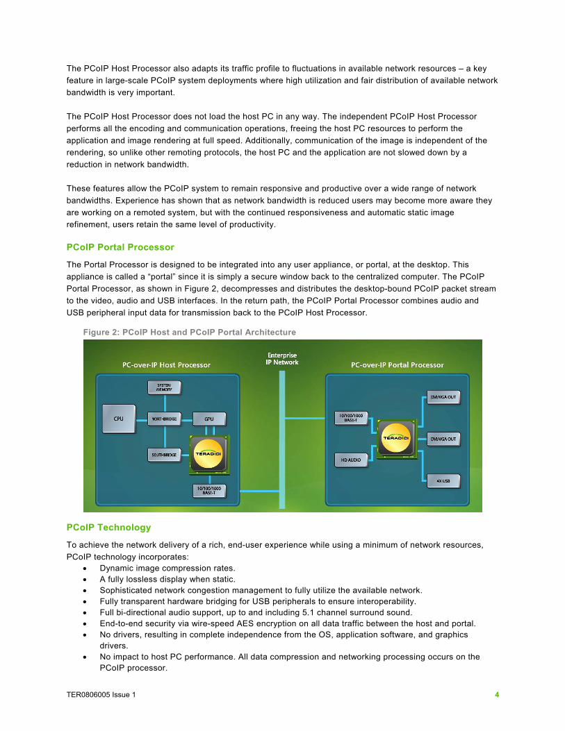
The Portal Processor is designed to be integrated into any user appliance, or portal, at the desktop. This appliance is called a “portal” since it is simply a secure window back to the centralized computer. The PCoIP Portal Processor, as shown in Figure 2, decompresses and distributes the desktop-bound PCoIP packet stream to the video, audio and USB interfaces. In the return path, the PCoIP Portal Processor combines audio and USB peripheral input data for transmission back to the PCoIP Host Processor.
Figure 2: PCoIP Host and PCoIP Portal Architecture
PCoIP Technology
To achieve the network delivery of a rich, end-user experience while using a minimum of network resources, PCoIP technology incorporates:
• Dynamic image compression rates. • A fully lossless display when static. • Sophisticated network congestion management to fully utilize the available network. • Fully transparent hardware bridging for USB peripherals to ensure interoperability. • Full bi-directional audio support, up to and including 5.1 channel surround sound. • End-to-end security via wire-speed AES encryption on all data traffic between the host and portal. • No drivers, resulting in complete independence from the OS, application software, and graphics
drivers. • No impact to host PC performance. All data compression and networking processing occurs on the
PCoIP processor.
TER0806005 Issue 1 5
Network Considerations In a PCoIP system, only the display and peripheral data leaves the corporate datacenter to the local user network. This changes the resource profile required compared to the traditional model of PCs and workstations located at the user’s desk. PCoIP Technology Networking Capability Summary:
• PCoIP host and portal are IPv4 based (IPv6 capable) with static or DHCP IP assignment • PCoIP host/portal devices have integrated 10/100/1000 Ethernet. • All PCoIP traffic is fully protected with IPSEC using wire-speed, hardware accelerated 128-bit AES
encryption and authentication. • PCoIP traffic is primarily point-to-point between host and the peer portal with the bandwidth typically
dominated by downstream host-to-portal traffic • PCoIP downstream bandwidth is determined primarily by user profile and screen resolution. Only
screen changes are transferred so that a static display requires virtually no downstream network bandwidth.
• Upstream traffic from portal to host is dominated by USB input data. • Progressive build is used to deliver an exact image of the rendered host PC display with a minimal
network loading. Progressive build increases system responsiveness by quickly delivering an initial image to the desktop while still supporting a fully lossless display image transfer.
• The total network bandwidth used is automatically adjusted by PCoIP host and portal devices by dynamically changing the compression ratios used. Users can select their preference for image quality or image responsiveness.
• Integrated traffic shaping allows source bandwidth metering and supports a hard device bandwidth limit setting.
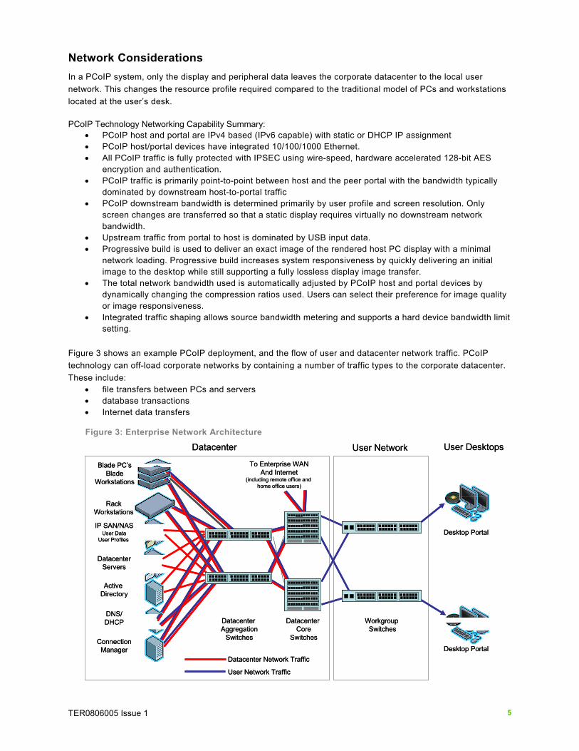
Figure 3 shows an example PCoIP deployment, and the flow of user and datacenter network traffic. PCoIP technology can off-load corporate networks by containing a number of traffic types to the corporate datacenter. These include:
• file transfers between PCs and servers • database transactions • Internet data transfers
Figure 3: Enterprise Network Architecture
Desktop Portal
Desktop Portal
Datacenter User Network
Workgroup Switches
Datacenter Aggregation
Switches
Datacenter Core
Switches
IP SAN/NASUser Data
User Profiles
ConnectionManager
Active Directory
DNS/DHCP
DatacenterServers
User Desktops
To Enterprise WANAnd Internet
(including remote office and home office users)
Datacenter Network Traffic
User Network Traffic
Blade PC’sBlade
Workstations
Rack Workstations
Desktop Portal
Desktop Portal
Datacenter User Network
Workgroup Switches
Datacenter Aggregation
Switches
Datacenter Core
Switches
IP SAN/NASUser Data
User Profiles
ConnectionManager
Active Directory
DNS/DHCP
DatacenterServers
User Desktops
To Enterprise WANAnd Internet
(including remote office and home office users)
Datacenter Network Traffic
User Network Traffic
Blade PC’sBlade
Workstations
Rack Workstations

TER0806005 Issue 1 6
The PCoIP Host Processor and PCoIP Portal Processor both generate network traffic between the centralized datacenter and the user desktop. To ensure desktop responsiveness, this process of compression, transmission, and rebuilding the desktop occurs in a very short time, typically less than 10ms. PCoIP Network Traffic
PCoIP network traffic contains traffic for image data, USB and HD audio peripheral bridging, and system management. The traffic profile is dominated by the downstream (host to portal) compressed image data. USB and audio-generated traffic typically have significantly lower bandwidth requirements than the image data. There is a negligible amount of bandwidth required for system management traffic. Imaging network bandwidth is only consumed during screen changes (opening/moving a window, high resolution video, etc.). Most office application scenarios are characterized by long periods with no screen changes, which result in long periods of virtually no network traffic. Overall bandwidth requirements are therefore based primarily on applications and usage scenarios, as well as on display resolution. Network Recommendations for PCoIP Deployments Today’s enterprise networks have evolved to the point where a full-scale PCoIP deployment is readily achievable and can fit within existing switched 100Mb/s workgroup/datacenter infrastructures. In a modern enterprise network, the available bandwidth is generally the same regardless of the direction from the datacenter. The dominant traffic in a PCoIP deployment is downstream (host to portal) so network sizing and requirements are specified on the link rates in the downstream direction. The following procedure allows IT administrators to generate a network configuration which can guarantee an excellent user experience for all the users on the PCoIP system. This procedure is a conservative estimate which guarantees a certain experience in the worst-case usage scenario where all active users are concurrently doing an operation which requires high imaging bandwidth (dragging windows or watching multimedia). This procedure is appropriate for deployments where the required amount of bandwidth is generally available, such as in LAN and campus networks. In cases where the required bandwidth is not available, the PCoIP host and portal pair will continue to operate by dynamically adjusting the network traffic generation to fit within the available network bandwidth. This is done in such a way to minimize any degradation in the user experience. In order to determine the network resources required for a PCoIP system deployment, IT administrators should consider the following steps:
1. Segment the user base by applications and display (Table 1). 2. Determine the per-user bandwidth allocation for each user type (see Table 3). 3. Determine the number of active users contributing to every link. 4. Determine link planning bandwidth for each network link. 5. Set the device bandwidth target for each PCoIP Host.
Definitions
Some key network bandwidth settings and considerations are defined below: Planning Bandwidth – defines the per-user bandwidth that will deliver the minimum desirable user experience, as defined by that user’s profile. The planning bandwidth includes requirements for all traffic types, including display image, USB, and audio data traffic. Table 3 provides conservative guidelines for the Planning Bandwidth for various user categories. Link Planning Bandwidth – defines the bandwidth required for a certain network link. It is defined as the sum of all the Planning Bandwidth’s of all the users who will be actively using the link at any one time.
TER0806005 Issue 1 7
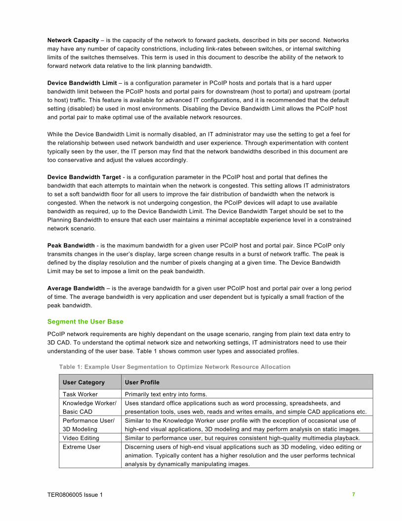
Network Capacity – is the capacity of the network to forward packets, described in bits per second. Networks may have any number of capacity constrictions, including link-rates between switches, or internal switching limits of the switches themselves. This term is used in this document to describe the ability of the network to forward network data relative to the link planning bandwidth. Device Bandwidth Limit – is a configuration parameter in PCoIP hosts and portals that is a hard upper bandwidth limit between the PCoIP hosts and portal pairs for downstream (host to portal) and upstream (portal to host) traffic. This feature is available for advanced IT configurations, and it is recommended that the default setting (disabled) be used in most environments. Disabling the Device Bandwidth Limit allows the PCoIP host and portal pair to make optimal use of the available network resources. While the Device Bandwidth Limit is normally disabled, an IT administrator may use the setting to get a feel for the relationship between used network bandwidth and user experience. Through experimentation with content typically seen by the user, the IT person may find that the network bandwidths described in this document are too conservative and adjust the values accordingly. Device Bandwidth Target - is a configuration parameter in the PCoIP host and portal that defines the bandwidth that each attempts to maintain when the network is congested. This setting allows IT administrators to set a soft bandwidth floor for all users to improve the fair distribution of bandwidth when the network is congested. When the network is not undergoing congestion, the PCoIP devices will adapt to use available bandwidth as required, up to the Device Bandwidth Limit. The Device Bandwidth Target should be set to the Planning Bandwidth to ensure that each user maintains a minimal acceptable experience level in a constrained network scenario. Peak Bandwidth - is the maximum bandwidth for a given user PCoIP host and portal pair. Since PCoIP only transmits changes in the user’s display, large screen change results in a burst of network traffic. The peak is defined by the display resolution and the number of pixels changing at a given time. The Device Bandwidth Limit may be set to impose a limit on the peak bandwidth. Average Bandwidth – is the average bandwidth for a given user PCoIP host and portal pair over a long period of time. The average bandwidth is very application and user dependent but is typically a small fraction of the peak bandwidth. Segment the User Base
PCoIP network requirements are highly dependant on the usage scenario, ranging from plain text data entry to 3D CAD. To understand the optimal network size and networking settings, IT administrators need to use their understanding of the user base. Table 1 shows common user types and associated profiles.
Table 1: Example User Segmentation to Optimize Network Resource Allocation
User Category User Profile
Task Worker Primarily text entry into forms. Knowledge Worker/ Basic CAD
Uses standard office applications such as word processing, spreadsheets, and presentation tools, uses web, reads and writes emails, and simple CAD applications etc.
Performance User/ 3D Modeling
Similar to the Knowledge Worker user profile with the exception of occasional use of high-end visual applications, 3D modeling and may perform analysis on static images.
Video Editing Similar to performance user, but requires consistent high-quality multimedia playback. Extreme User Discerning users of high-end visual applications such as 3D modeling, video editing or
animation. Typically content has a higher resolution and the user performs technical analysis by dynamically manipulating images.
TER0806005 Issue 1 8
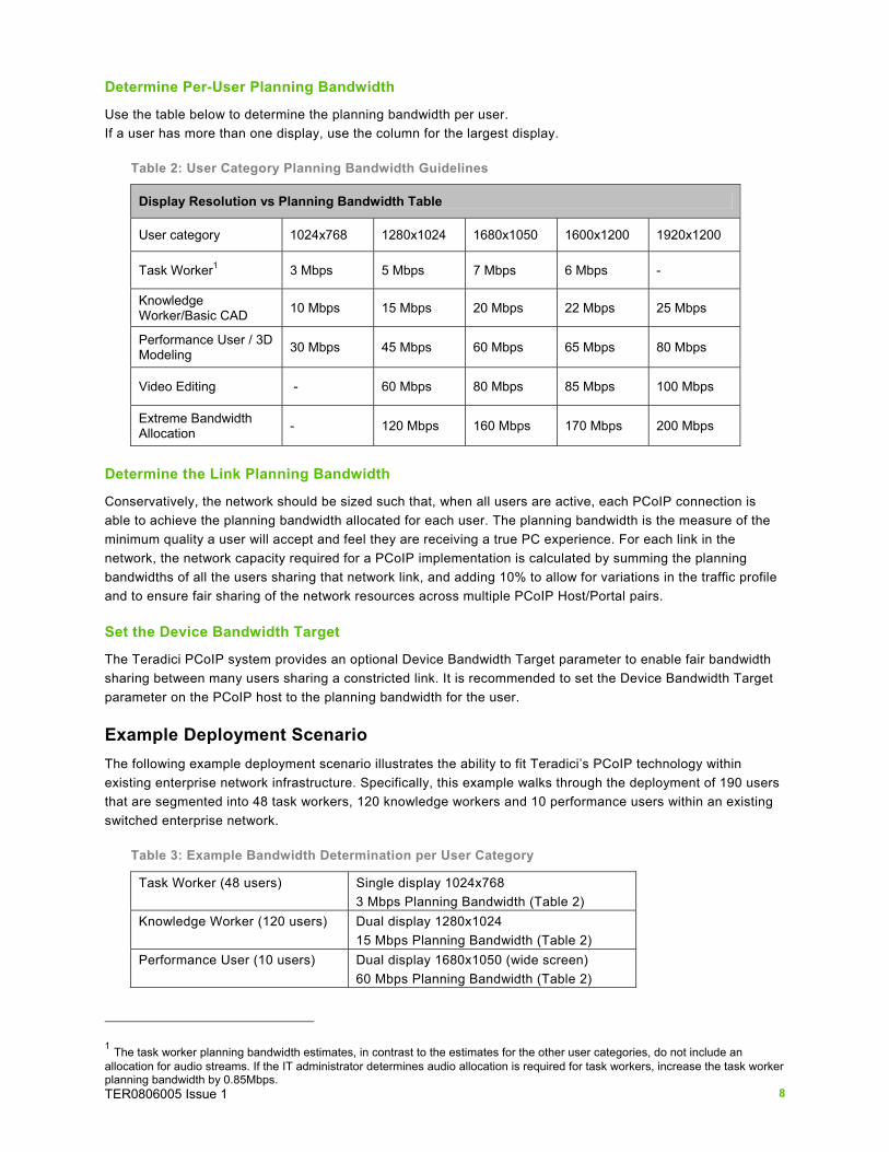
Determine Per-User Planning Bandwidth
Use the table below to determine the planning bandwidth per user. If a user has more than one display, use the column for the largest display.
Table 2: User Category Planning Bandwidth Guidelines
Display Resolution vs Planning Bandwidth Table
User category 1024x768 1280x1024 1680x1050 1600x1200 1920x1200
Task Worker1 3 Mbps 5 Mbps 7 Mbps 6 Mbps -
Knowledge Worker/Basic CAD 10 Mbps 15 Mbps 20 Mbps 22 Mbps 25 Mbps
Performance User / 3D Modeling 30 Mbps 45 Mbps 60 Mbps 65 Mbps 80 Mbps
Video Editing - 60 Mbps 80 Mbps 85 Mbps 100 Mbps
Extreme Bandwidth Allocation - 120 Mbps 160 Mbps 170 Mbps 200 Mbps
Determine the Link Planning Bandwidth
Conservatively, the network should be sized such that, when all users are active, each PCoIP connection is able to achieve the planning bandwidth allocated for each user. The planning bandwidth is the measure of the minimum quality a user will accept and feel they are receiving a true PC experience. For each link in the network, the network capacity required for a PCoIP implementation is calculated by summing the planning bandwidths of all the users sharing that network link, and adding 10% to allow for variations in the traffic profile and to ensure fair sharing of the network resources across multiple PCoIP Host/Portal pairs. Set the Device Bandwidth Target
The Teradici PCoIP system provides an optional Device Bandwidth Target parameter to enable fair bandwidth sharing between many users sharing a constricted link. It is recommended to set the Device Bandwidth Target parameter on the PCoIP host to the planning bandwidth for the user. Example Deployment Scenario The following example deployment scenario illustrates the ability to fit Teradici’s PCoIP technology within existing enterprise network infrastructure. Specifically, this example walks through the deployment of 190 users that are segmented into 48 task workers, 120 knowledge workers and 10 performance users within an existing switched enterprise network.
Table 3: Example Bandwidth Determination per User Category
Task Worker (48 users) Single display 1024x768 3 Mbps Planning Bandwidth (Table 2)
Knowledge Worker (120 users)
Dual display 1280x1024 15 Mbps Planning Bandwidth (Table 2)
Performance User (10 users) Dual display 1680x1050 (wide screen) 60 Mbps Planning Bandwidth (Table 2)
1 The task worker planning bandwidth estimates, in contrast to the estimates for the other user categories, do not include an allocation for audio streams. If the IT administrator determines audio allocation is required for task workers, increase the task worker planning bandwidth by 0.85Mbps.
TER0806005 Issue 1 9
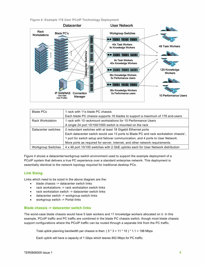
Figure 4: Example 178 User PCoIP Technology Deployment
36x Knowledge Workers5x Performance users
48 Task Workers
120 KnowledgeWorkers
10 Performance Users
36x Knowledge Workers5x Performance Users
8x Task Workers40x Knowledge Workers
40x Task Workers8x Knowledge Workers
IP SAN/NASUser Data
User Profiles
Datacenter User Network
ConnectionManager
Blade PC’s Workgroup Switches
Dat
acen
ter S
witc
hes
Rack Workstations
Blade PCs 1 rack with 11x blade PC chassis Each blade PC chassis supports 16 blades to support a maximum of 176 end-users
Rack Workstation 1 rack with 10 rackmount workstations for 10 Performance Users A single 24 port 10/100/1000 switch is mounted on the rack
Datacenter switches 2 redundant switches with at least 18 Gigabit Ethernet ports Each datacenter switch would use 13 ports to Blade PC and rack workstation chassis’, 1 port for switch setup and failover communication, and 4 ports to User Network. More ports as required for server, internet, and other network requirements.
Workgroup Switches 4 x 48 port 10/100 switches with 2 GbE uplinks each for User Network distribution Figure 4 shows a datacenter/workgroup switch environment used to support the example deployment of a PCoIP system that delivers a true PC experience over a standard enterprise network. This deployment is essentially identical to the network topology required for traditional desktop PCs. Link Sizing
Links which need to be sized in the above diagram are the: • blade chassis -> datacenter switch links • rack workstations -> rack workstation switch links • rack workstation switch -> datacenter switch links • datacenter switch -> workgroup switch links • workgroup switch -> Portal links
Blade chassis -> datacenter switch links
The worst-case blade chassis would have 5 task workers and 11 knowledge workers allocated on it. In this example, PCoIP traffic and PC traffic are combined in the blade PC chassis switch, though most blade chassis support configurations where the PCoIP traffic can be routed through a separate link from the PC traffic.
Total uplink planning bandwidth per chassis is then: ( 5 * 3 + 11 * 15 ) * 1.1 = 198 Mbps Each uplink will have a capacity of 1 Gbps which leaves 802 Mbps for PC traffic.

TER0806005 Issue 1 10
Rack workstations -> rack workstation switch links
Each rack workstation receives two Gigabit Ethernet connections to the rack workstation switch, one for the PC and one for the PCoIP traffic.
Planning Bandwidth for each PCoIP link is: 60 * 1.1 = 66 Mbps Rack workstation switch -> datacenter switch links
Each rack workstation switch has a single Gigabit Ethernet connection to each datacenter switch.
Planning Bandwidth for the PCoIP traffic on the link is: 10* 60 * 1.1 = 660 Mbps, leaving 340 Mbps for PC traffic.
Datacenter switch -> workgroup switch links
There are three switch configurations: A: 2 switches supporting 36 knowledge workers and 5 performance users B: 1 switch supporting 40 task workers and 8 knowledge workers C: 1 switch supporting 40 knowledge workers and 8 task workers
The datacenter to workgroup switch links would then need to be sized:
A: (36 * 15 + 5 * 60) * 1.1 = 924 Mbps B: (40 * 3 + 8 * 15) * 1.1 = 264 Mbps C: (8 * 3 + 40 * 15) * 1.1 = 686 Mbps
In each case, less than 1 Gbps is required, so a single Gigabit uplink to the datacenter switches is sufficient. Workgroup switch -> Portal links
In all cases, the planning bandwidth for each user is less than the 100 Mbps available for each link, so the standard 100-base-T connections are sufficient. Datacenter switches
In this network configuration, only a single datacenter switch would be required to meet all the traffic needs. To allow for network fault tolerance, two datacenter switches are connected to the network. Since each connection to a datacenter switch requires less than the available Gigabit link rates, a simple active/passive redundancy scheme is acceptable, where one switch takes all of the network traffic unless there is a failover. Where required, active/active redundancy can be implemented, using protocols such as Multiple Spanning Tree Protocol (MSTP), Cisco VSS, or Nortel SMLT. Using these protocols is transparent to the PCoIP connections. Each switch would have an identical configuration. The final per-switch configuration would be:
• 1 Gigabit Ethernet port between the two switches, to allow for setup and failover communication • 12 Gigabit Ethernet ports to the blade chassis • 1 Gigabit Ethernet port to the workstation rack • 4 Gigabit Ethernet ports to the workgroup switches • Plus a number of ports for other server and internet connections
VLAN and QoS Considerations PCoIP technology was developed to work over standard IP networks without requiring special configurations. As such, virtual LAN (VLAN) and Quality of Service (QoS) settings are not required for system operation. In cases where the network is shared between PCoIP traffic and other data traffic, and the IT administrator wishes to guarantee a certain amount of bandwidth to PCoIP traffic, VLAN and QoS settings can be used within the network switches.
TER0806005 Issue 1 11
Off-Campus Network Considerations In an off-campus remoting environment (WAN or MAN), IT administrators will encounter a number of items which need special attention. These include:
• restricted bandwidth environments • network latency • firewalls and virtual private networks (VPN’s)
Restricted Bandwidth Environments In cases where the planning bandwidth is not available, the IT administrator needs to make tradeoffs to achieve the optimal experience. In these cases the IT administrator should take the average bandwidth usage as well as USB and audio traffic into account. Minimum Bandwidth Requirements – At a minimum, 3 Mbps peak bandwidth per user is required to be available for reliable system operation. Average versus Planning Bandwidth
The average bandwidth used will typically be significantly lower than the planning bandwidth for users doing interactive operations. Measurements have shown task workers consuming less than 200 kbps average, and knowledge workers consuming less than 1 Mbps on average. IT administrators can take advantage of this when planning their network deployments by measuring the requirements of their target users. USB and Audio Considerations
In restricted bandwidth environments, USB and audio traffic can be a significant factor in overall bandwidth usage. For USB traffic, keyboard and mouse traffic remains small but IT administrators should budget for a certain amount of data transfers to occur. USB – upstream (input) or downstream (output) traffic that can range up to 12 Mbps in either direction. Keyboard and mouse USB traffic requires significantly less than 1Mbps. USB traffic is not compressed and can be allocated based on the user segment’s USB peripheral throughput needs. Audio traffic requires low peak bandwidth but it can significantly affect a user’s average bandwidth requirements. Audio – For HD audio, up to 3 Mbps bandwidth allocation is required downstream to the speakers and 1.5 Mbps upstream from the microphone. For low bandwidth situations, audio may be compressed resulting in a per user audio bandwidth as low as 800Kbps in each direction audio is used. Network Latency Considerations In general, to provide system responsiveness comparable to a traditional desktop, the round trip network latency should ideally be less than 30ms. This requirement easily fits within corporate or campus LAN infrastructures. The hardware advantages of PC-over-IP technology help mitigate the impact of high latency links to deliver an exceptional user experience. Optimizations for network latencies >30ms will be covered in a separate document. NAT Considerations PC-over-IP® traffic cannot undergo network address translation (NAT). The Host and destination IP addresses cannot be modified as the packets move between the host and the portal. To support NAT, PC-over-IP® traffic can be tunneled through a VPN.
TER0806005 Issue 1 12
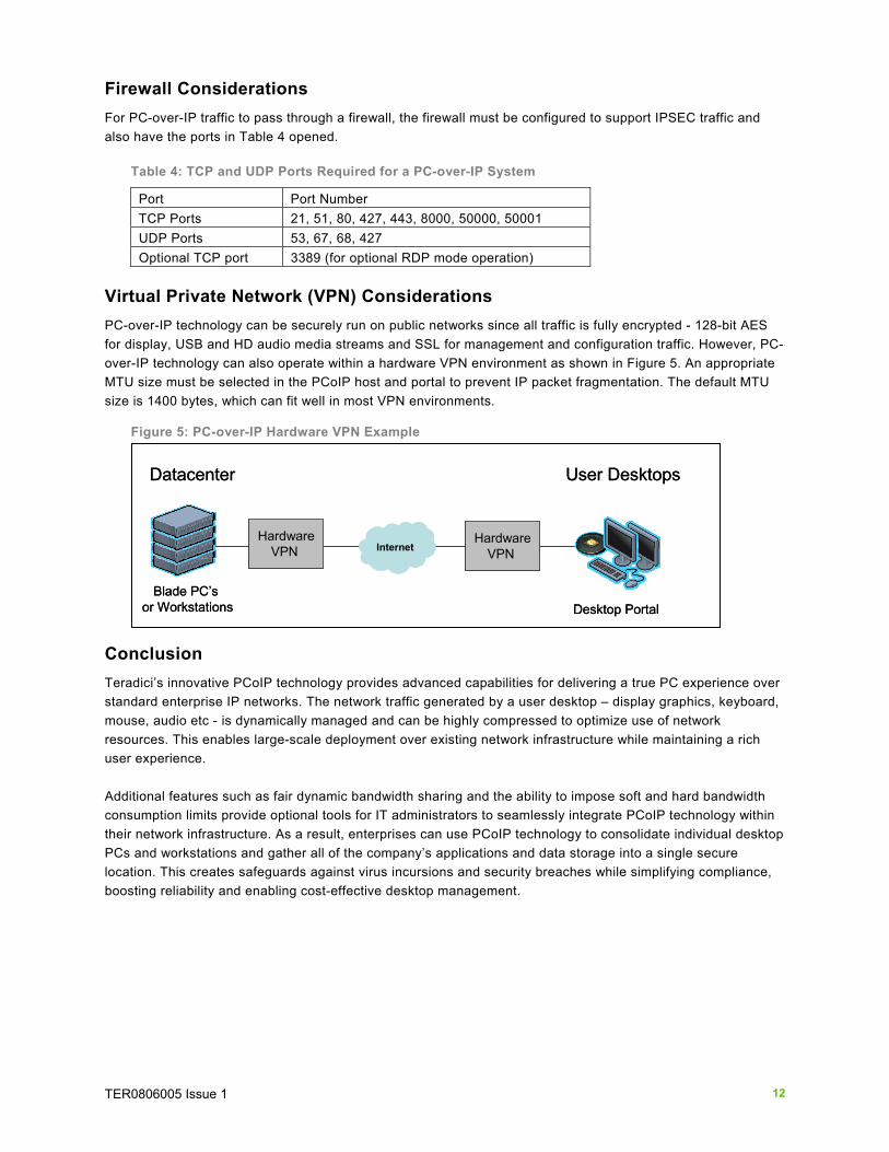
Firewall Considerations For PC-over-IP traffic to pass through a firewall, the firewall must be configured to support IPSEC traffic and also have the ports in Table 4 opened.
Table 4: TCP and UDP Ports Required for a PC-over-IP System
Port Port Number TCP Ports 21, 51, 80, 427, 443, 8000, 50000, 50001 UDP Ports 53, 67, 68, 427 Optional TCP port 3389 (for optional RDP mode operation)
Virtual Private Network (VPN) Considerations PC-over-IP technology can be securely run on public networks since all traffic is fully encrypted - 128-bit AES for display, USB and HD audio media streams and SSL for management and configuration traffic. However, PC-over-IP technology can also operate within a hardware VPN environment as shown in Figure 5. An appropriate MTU size must be selected in the PCoIP host and portal to prevent IP packet fragmentation. The default MTU size is 1400 bytes, which can fit well in most VPN environments.
Figure 5: PC-over-IP Hardware VPN Example
Conclusion Teradici’s innovative PCoIP technology provides advanced capabilities for delivering a true PC experience over standard enterprise IP networks. The network traffic generated by a user desktop – display graphics, keyboard, mouse, audio etc - is dynamically managed and can be highly compressed to optimize use of network resources. This enables large-scale deployment over existing network infrastructure while maintaining a rich user experience. Additional features such as fair dynamic bandwidth sharing and the ability to impose soft and hard bandwidth consumption limits provide optional tools for IT administrators to seamlessly integrate PCoIP technology within their network infrastructure. As a result, enterprises can use PCoIP technology to consolidate individual desktop PCs and workstations and gather all of the company’s applications and data storage into a single secure location. This creates safeguards against virus incursions and security breaches while simplifying compliance, boosting reliability and enabling cost-effective desktop management.
Desktop PortalBlade PC’s
or Workstations
HardwareVPN
HardwareVPN
Datacenter User Desktops
Internet
Desktop PortalBlade PC’s
or Workstations
HardwareVPN
HardwareVPN
Datacenter User Desktops
Internet

TER0806005 Issue 1 13
Teradici Corporation #500-4400 Dominion St. Burnaby, B.C. V5G 4G3 Canada p+1 604 451 5800 f+1 604 451 5818 www.teradici.com
The information contained in this document represents the current view of Teradici Corporation as of the date of publication. Because Teradici must respond to changing market conditions, it should not be interpreted to be a commitment on the part of Teradici, and Teradici cannot guarantee the accuracy of any information presented after the date of publication. This document is for informational purposes only. TERADICI MAKES NO WARRANTIES, EXPRESS, IMPLIED OR STATUTORY, AS TO THE INFORMATION IN THIS DOCUMENT. Complying with all applicable copyright laws is the responsibility of the user. Without limiting the rights under copyright, no part of this document may be reproduced, stored in or introduced into a retrieval system, or transmitted in any form or by any means (electronic, mechanical, photocopying, recording, or otherwise), or for any purpose, without the express written permission of Teradici Corporation. Teradici may have patents, patent applications, trademarks, copyrights, or other intellectual property rights covering subject matter in this document. Except as expressly provided in any written license agreement from Teradici, the furnishing of this document does not give you any license to these patents, trademarks, copyrights, or other intellectual property. © 2008 Teradici Corporation. All rights reserved. Teradici, PC-over-IP, and PCoIP are registered trademarks of Teradici Corporation. The names of actual companies and products mentioned herein may be the trademarks of their respective owners.