PAVERS - Amazon Web Servicestecho-bloc.s3.amazonaws.com/...Installation_CAN_Pavers_ALL_Cover.pdf16"...
11
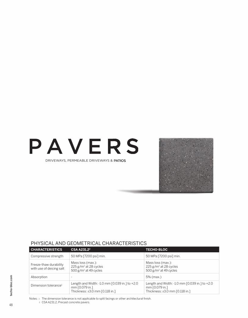
48 techo-bloc.com PAVERS DRIVEWAYS, PERMEABLE DRIVEWAYS & PATIOS PHYSICAL AND GEOMETRICAL CHARACTERISTICS CHARACTERISTICS CSA A231.2 2 TECHO-BLOC Compressive strength 50 MPa [7200 psi] min. 50 MPa [7200 psi] min. Freeze-thaw durability with use of deicing salt Mass loss (max.): 225 g/m 2 at 28 cycles 500 g/m 2 at 49 cycles Mass loss (max.): 225 g/m 2 at 28 cycles 500 g/m 2 at 49 cycles Absorption - 5% (max.) Dimension tolerance 1 Length and Width: -1.0 mm [0.039 in.] to +2.0 mm [0.079 in.] Thickness: ±3.0 mm [0.118 in.] Length and Width: -1.0 mm [0.039 in.] to +2.0 mm [0.079 in.] Thickness: ±3.0 mm [0.118 in.] Notes : 1. The dimension tolerance is not applicable to split facings or other architectural finish. 2. CSA A231.2, Precast concrete pavers.
Transcript of PAVERS - Amazon Web Servicestecho-bloc.s3.amazonaws.com/...Installation_CAN_Pavers_ALL_Cover.pdf16"...
48
tech
o-b
loc.
com
PAVERS
P A V E R SDRIVEWAYS, PERMEABLE DRIVEWAYS & PATIOS
P A V E R SDRIVEWAYS, PERMEABLE DRIVEWAYS & PATIOS
PHYSICAL AND GEOMETRICAL CHARACTERISTICSCHARACTERISTICS CSA A231.22 TECHO-BLOC
Compressive strength 50 MPa [7200 psi] min. 50 MPa [7200 psi] min.
Freeze-thaw durabilitywith use of deicing salt
Mass loss (max.):225 g/m2 at 28 cycles500 g/m2 at 49 cycles
Mass loss (max.):225 g/m2 at 28 cycles500 g/m2 at 49 cycles
Absorption - 5% (max.)
Dimension tolerance1 Length and Width: -1.0 mm [0.039 in.] to +2.0 mm [0.079 in.]Thickness: ±3.0 mm [0.118 in.]
Length and Width: -1.0 mm [0.039 in.] to +2.0 mm [0.079 in.]Thickness: ±3.0 mm [0.118 in.]
Notes : 1. The dimension tolerance is not applicable to split facings or other architectural fi nish.2. CSA A231.2, Precast concrete pavers.Pavers

PA
VE
RS
49
tech
o-b
loc.
com
Installation guideTYPICAL APPLICATION USAGE
SECTOR TRAFFIC TYPE & APPLICATIONS PAVERS
RESIDENTIAL
1. Light trafficCars and occasionallight service trucks(ex. residential driveways)
- Allegro- Antika- Blu 80 mm- Blu 80 mm (6 x 13)- Eva- Flagstone- Linea (small rectangles)- Mista Grande- Mista Random- Mista Square- Parisien (square, rectangle, circle)- San Marino (small rectangles)- Sleek- Valet- Victorien 60 mm- Villagio - All products from traffic type 2 & 3.
ICI
(Industrial, Commercial and
Institutional)
2. Road trafficCars, heavy trucks, buses (ex. boulevards, main or secondary streets, pedestrian crossings, industrial, ports and airport areas)
- Industria 200 x 200- Industria 300 x 100- Industria 300 x 150- Industria 300 x 300
3. Light trafficCars and occasionallight service trucks(ex. parking lots, sidewalks)
- Industria 200 x 400- Industria 600 x 300- Industria 600 x 600- Linea (large rectangles)- San Marino (large rectangles)- All products from traffic type 2.
4. PedestrianPedestrian only and at all times, without cars, or trucks or other mobile equipment (ex. terraces, parks, pedestrian walkways)
- Blu 80 mm (6 x 13)- Industria 600 x 100- Industria 600 x 200- Linea (small rectangles)- San Marino (small rectangles)- Sleek- All products from traffic type 2 & 3.
PA
VE
RS
50
tech
o-b
loc.
com
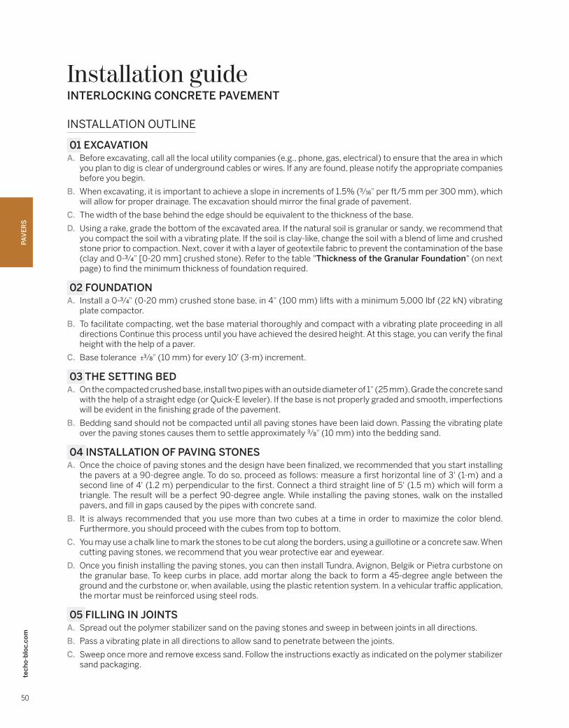
Installation guideINTERLOCKING CONCRETE PAVEMENT
INSTALLATION OUTLINE
01 EXCAVATIONA. Before excavating, call all the local utility companies (e.g., phone, gas, electrical) to ensure that the area in which
you plan to dig is clear of underground cables or wires. If any are found, please notify the appropriate companies before you begin.
B. When excavating, it is important to achieve a slope in increments of 1.5% (3⁄16" per ft/5 mm per 300 mm), which will allow for proper drainage. The excavation should mirror the final grade of pavement.
C. The width of the base behind the edge should be equivalent to the thickness of the base.
D. Using a rake, grade the bottom of the excavated area. If the natural soil is granular or sandy, we recommend that you compact the soil with a vibrating plate. If the soil is clay-like, change the soil with a blend of lime and crushed stone prior to compaction. Next, cover it with a layer of geotextile fabric to prevent the contamination of the base (clay and 0-3⁄4" [0-20 mm] crushed stone). Refer to the table "Thickness of the Granular Foundation" (on next page) to find the minimum thickness of foundation required.
02 FOUNDATIONA. Install a 0-3⁄4" (0-20 mm) crushed stone base, in 4" (100 mm) lifts with a minimum 5,000 lbf (22 kN) vibrating
plate compactor.
B. To facilitate compacting, wet the base material thoroughly and compact with a vibrating plate proceeding in all directions Continue this process until you have achieved the desired height. At this stage, you can verify the final height with the help of a paver.
C. Base tolerance ±3⁄8" (10 mm) for every 10' (3-m) increment.
03 THE SETTING BEDA. On the compacted crushed base, install two pipes with an outside diameter of 1" (25 mm). Grade the concrete sand
with the help of a straight edge (or Quick-E leveler). If the base is not properly graded and smooth, imperfections will be evident in the finishing grade of the pavement.
B. Bedding sand should not be compacted until all paving stones have been laid down. Passing the vibrating plate over the paving stones causes them to settle approximately 3⁄8" (10 mm) into the bedding sand.
04 INSTALLATION OF PAVING STONESA. Once the choice of paving stones and the design have been finalized, we recommended that you start installing
the pavers at a 90-degree angle. To do so, proceed as follows: measure a first horizontal line of 3' (1-m) and a second line of 4' (1.2 m) perpendicular to the first. Connect a third straight line of 5' (1.5 m) which will form a triangle. The result will be a perfect 90-degree angle. While installing the paving stones, walk on the installed pavers, and fill in gaps caused by the pipes with concrete sand.
B. It is always recommended that you use more than two cubes at a time in order to maximize the color blend. Furthermore, you should proceed with the cubes from top to bottom.
C. You may use a chalk line to mark the stones to be cut along the borders, using a guillotine or a concrete saw. When cutting paving stones, we recommend that you wear protective ear and eyewear.
D. Once you finish installing the paving stones, you can then install Tundra, Avignon, Belgik or Pietra curbstone on the granular base. To keep curbs in place, add mortar along the back to form a 45-degree angle between the ground and the curbstone or, when available, using the plastic retention system. In a vehicular traffic application, the mortar must be reinforced using steel rods.
05 FILLING IN JOINTSA. Spread out the polymer stabilizer sand on the paving stones and sweep in between joints in all directions.
B. Pass a vibrating plate in all directions to allow sand to penetrate between the joints.
C. Sweep once more and remove excess sand. Follow the instructions exactly as indicated on the polymer stabilizer sand packaging.

PA
VE
RS
51
tech
o-b
loc.
com
Installation guide
VIBRATING PLATE ALERT! Avoid scuffs on paver surfaces.Pavers with embossed surfaces (high and low points) are more susceptible to scuff marks from plate compactors. Techo‑Bloc recommends the use of urethane mats between the plate and the paver surface when compacting. Techo‑Bloc will not be held responsible for compaction scuffs or burns on pavers.
THICKNESS OF THE GRANULAR FOUNDATION1
RESIDENTIAL PROJECTSTYPE OF EXISTING SOIL
Clayey or Silty2 Sandy or Gravelly
Driveways 300 to 500 mm (12" to 20") 200 to 350 mm (8" to 14")
Patios and Walkways 250 to 350 mm (10" to 14") 150 to 200 mm (6" to 8")
1. Data shown in this chart are provided as guidelines only. The range of values suggested depends particularly on existing soil conditions. The thicker the granular foundation, the greater the increase in stability of the whole structure.
2. In the case of unstable soils or ones particularly affected by the freeze-thaw cycles, a thicker foundation may be necessary. For soils with these conditions or for commercial, industrial, or institutional works, a geotechnical professional should be consulted.
QUANTITY CHART FOR JOINTS FILLING Approximate surface coverage per 50 lbs (22.7 kg) polymeric sand bag.
INTERLOCKING CONCRETE PAVEMENT
PRODUCTS sq. ft sq. m
Allegro 38 3.5
Antika 21 2
Blu 80 mm 76.5 7.11
Blu 80 mm (6"×13") 31.97 2.97
Eva 143.56 13.34
Flagstone 66 6.13
Industria 200 series - 200×200 41.03 3.81
Industria 200 series - 200×400 54.57 5.07
Industria 300 series - 300×100 30.77 2.86
Industria 300 series - 300×200 41 3.81
Industria 300 series - 300×300 61.39 5.70
Industria 600 series - 600×100 35.06 3.26
Industria 600 series - 600×200 61.32 5.70
Industria 600 series - 600×300 81.72 7.59
Industria 600 series - 600×600 122.48 11.38
Linea and San Marino small rectangles
31.47 2.92
Linea and San Marino large rectangles
42.33 3.93
Mista random 50.4 4.69
Mista square 65.6 6.10
Mista Grande 25.67 2.38
Parisien square 100.64 9.35
Parisien rectangle 120.55 11.20
Parisien circle 49.25 4.58
Sleek 76.5 7.1
PRODUCTS sq. ft sq. m
Valet 24.1 2.2
Victorien 60 mm 97.06 9.02
Victorien 80 mm 72.79 6.76
Villagio 18.50 1.72
TYPICAL PAVER CROSS SECTION WITH PLASTIC EDGE
A. TECHO-BLOC PRECAST CONCRETE PAVER 2 3⁄8" (60 mm) THICK MIN.
B. SAND JOINT FILL
C. SAND SETTING BED (CONCRETE SAND) 1" (25 mm)
D. EXTRA WIDTH EQUAL TO FOUNDATION THICKNESS
E. LAWN
F. PLASTIC EDGE
G. NAIL
H. GEOTEXTILE
I. COMPACTED GRANULAR BASE 0-3⁄4" (0-20 mm)
J. SUBGRADE
85
tech
o-b
loc.
com
Pavers
P E R M E A B L EP A V E R S
DRIVEWAYS, PERMEABLE DRIVEWAYS & PATIOS
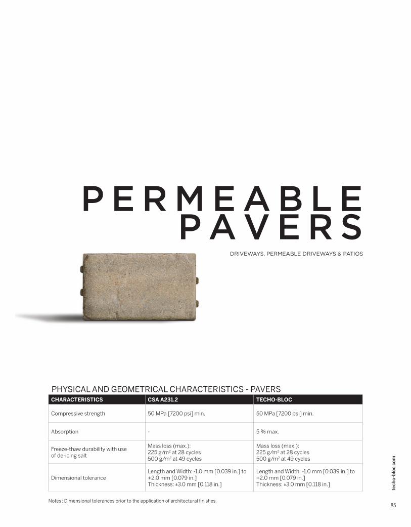
PHYSICAL AND GEOMETRICAL CHARACTERISTICS - PAVERS CHARACTERISTICS CSA A231.2 TECHO-BLOC
Compressive strength 50 MPa [7200 psi] min. 50 MPa [7200 psi] min.
Absorption - 5 % max.
Freeze-thaw durability with useof de-icing salt
Mass loss (max.): 225 g/m2 at 28 cycles500 g/m2 at 49 cycles
Mass loss (max.):225 g/m2 at 28 cycles500 g/m2 at 49 cycles
Dimensional toleranceLength and Width: -1.0 mm [0.039 in.] to +2.0 mm [0.079 in.]Thickness: ±3.0 mm [0.118 in.]
Length and Width: -1.0 mm [0.039 in.] to +2.0 mm [0.079 in.]Thickness: ±3.0 mm [0.118 in.]
Notes : Dimensional tolerances prior to the application of architectural fi nishes.
Permeable pavers
General technical information

86
tech
o-b
loc.
com
Installation guide
PE
RM
EA
BLE
PA
VE
RS
SECTOR TRAFFIC TYPE & APPLICATIONS PERMEABLE PAVERS
RESIDENTIAL
1. Light traffic
Cars and occasionallight service trucks(ex. residential driveways)
- Antika
- Blu 80 mm
- Inflo
- Mista Random
- Pure
- Valet
- Victorien 60 mm permeable
- Villagio
2. Pedestrian
Pedestrian only and at all times (ex. patios)
- Antika
- Blu 80 mm
- Blu 60 mm
- Inflo
- Mista Random
- Pure
- Valet
- Victorien 60 mm permeable
- Villagio
ICI
(Industrial, Commercial and
Institutional)
3. Road traffic
Cars, heavy trucks, buses (ex. boulevards, main or secondary streets, pedestrian crossings, industrial, ports and airport areas)
- Inflo
4. Light traffic
Cars and occasionallight service trucks(ex. parking lots, sidewalks)
- Inflo
- Pure
5. Pedestrian
Pedestrian only and at all times, without cars, or trucks or other mobile equipment (ex. terraces, parks, pedestrian walkways)
- Inflo
- Pure
TYPICAL APPLICATION USAGE

87
tech
o-b
loc.
com
Installation guide
PE
RM
EA
BLE
PA
VE
RS
INFILTRATION CHART
Blu 60 mm SLAB
(page 28 to 33)
Antika PAVER
(page 53)
Blu 80 mm PAVER
(page 54 to 58)
Mista Random PAVER
(page 72)
Valet PAVER
(page 81)
Villagio PAVER
(page 83)
OTHER PERMEABLE POSSIBILITIES
PERMEABLE PAVERSPERCENT OF SURFACE
OPENING (%)JOINT WIDTH (mm)
INFILTRATION RATE1
(mm/h)
ANTIKA2 Variable Variable 993 in./hr (25 227 mm/hr)
BLU 80 mm2 3.0 9⁄32" (7 mm) 570 in./hr (14 475 mm/hr)
INFLO1 5.8 1⁄2" (13 mm) 837 in./hr (21 267 mm/hr)
MISTA random1 6.3 3⁄16" (4 mm) to 9⁄16" (14 mm) 610 in./hr (15 505 mm/hr)
PURE2 5.0 3⁄8" (10 mm) 726 in./hr (18 440 mm/hr)
VALET 5.9 9⁄32" (7 mm) to come
VICTORIEN 60 mm permeable1 9.6 3⁄8" (10 mm) 909 in./hr (23 085 mm/hr)
VILLAGIO1 8.0 3⁄8" (9 mm) to 9⁄16" (15 mm) 896 in./hr (22 750 mm/hr)
PERMEABLE SLABPERCENT OF SURFACE
OPENING (%)JOINT WIDTH (mm)
INFILTRATION RATE1
(mm/h)
BLU 60 mm2 3.0 9⁄32" (7 mm) 570 in./hr (14 475 mm/hr)
1 Measurements were taken at various sites in conformity to the standard ASTM C 1701-09.2 Measurements were taken at various sites in conformity to the standard ASTM C 1781.
88
tech
o-b
loc.
com
Installation guide
PE
RM
EA
BLE
PA
VE
RS
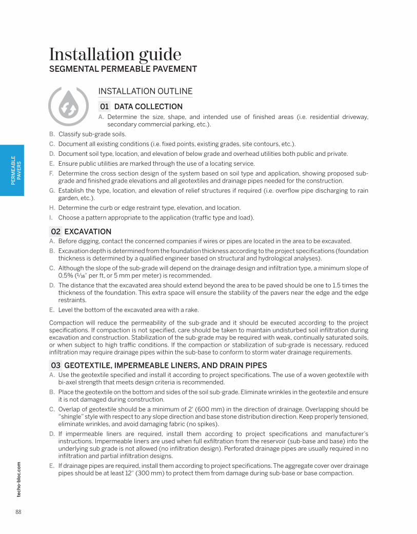
INSTALLATION OUTLINE
01 DATA COLLECTIONA. Determine the size, shape, and intended use of finished areas (i.e. residential driveway,
secondary commercial parking, etc.).
B. Classify sub-grade soils.
C. Document all existing conditions (i.e. fixed points, existing grades, site contours, etc.).
D. Document soil type, location, and elevation of below grade and overhead utilities both public and private.
E. Ensure public utilities are marked through the use of a locating service.
F. Determine the cross section design of the system based on soil type and application, showing proposed sub-grade and finished grade elevations and all geotextiles and drainage pipes needed for the construction.
G. Establish the type, location, and elevation of relief structures if required (i.e. overflow pipe discharging to rain garden, etc.).
H. Determine the curb or edge restraint type, elevation, and location.
I. Choose a pattern appropriate to the application (traffic type and load).
02 EXCAVATIONA. Before digging, contact the concerned companies if wires or pipes are located in the area to be excavated.
B. Excavation depth is determined from the foundation thickness according to the project specifications (foundation thickness is determined by a qualified engineer based on structural and hydrological analyses).
C. Although the slope of the sub-grade will depend on the drainage design and infiltration type, a minimum slope of 0.5% (1⁄16" per ft, or 5 mm per meter) is recommended.
D. The distance that the excavated area should extend beyond the area to be paved should be one to 1.5 times the thickness of the foundation. This extra space will ensure the stability of the pavers near the edge and the edge restraints.
E. Level the bottom of the excavated area with a rake.
Compaction will reduce the permeability of the sub-grade and it should be executed according to the project specifications. If compaction is not specified, care should be taken to maintain undisturbed soil infiltration during excavation and construction. Stabilization of the sub-grade may be required with weak, continually saturated soils, or when subject to high traffic conditions. If the compaction or stabilization of sub-grade is necessary, reduced infiltration may require drainage pipes within the sub-base to conform to storm water drainage requirements.
03 GEOTEXTILE, IMPERMEABLE LINERS, AND DRAIN PIPES A. Use the geotextile specified and install it according to project specifications. The use of a woven geotextile with
bi-axel strength that meets design criteria is recommended.
B. Place the geotextile on the bottom and sides of the soil sub-grade. Eliminate wrinkles in the geotextile and ensure it is not damaged during construction.
C. Overlap of geotextile should be a minimum of 2' (600 mm) in the direction of drainage. Overlapping should be “shingle” style with respect to any slope direction and base stone distribution direction. Keep properly tensioned, eliminate wrinkles, and avoid damaging fabric (no spikes).
D. If impermeable liners are required, install them according to project specifications and manufacturer’s instructions. Impermeable liners are used when full exfiltration from the reservoir (sub-base and base) into the underlying sub grade is not allowed (no infiltration design). Perforated drainage pipes are usually required in no infiltration and partial infiltration designs.
E. If drainage pipes are required, install them according to project specifications. The aggregate cover over drainage pipes should be at least 12" (300 mm) to protect them from damage during sub-base or base compaction.
SEGMENTAL PERMEABLE PAVEMENT

89
tech
o-b
loc.
com
Installation guide
PE
RM
EA
BLE
PA
VE
RS
04 SUB-BASE
For residential pedestrian applications, the sub-base may not be required and then only ASTM No. 57 (CSA 5-28) aggregate base layer with a minimum thickness of 6" (150 mm) can be used (use a thicker base for additional water storage). Refer to Base (see below 06).
When traffic load, soil conditions, and climate require greater than 12" (300 mm) of base or volume requirements for detention are higher, a sub-base may be required. Use sub-base ASTM No. 2 or No. 3 (CSA 40-80) meeting the following requirements:
• 90% fractured symmetrical particles
• Less than 5% passing the 200 sieve
• Industry hardness tested
A. Moisten, spread and compact the ASTM No. 2 (CSA 40-80) aggregate sub-base in minimum 6" (150 mm) lifts (without distorting or damaging the geotextile) according to the project specifications.
B. Make at least two passes in the vibratory mode followed by at least two passes in the static mode with a minimum 10 ton (9 metric ton) vibratory roller, until there is no visible movement of the aggregate. Alternately, a 13,500 lbf (60 kN) plate compactor can be used to compact the ASTM No. 2 (CSA 40-80) aggregate sub-base.
C. Do not allow the compactor to crush the aggregate.
D. Surface tolerance of the ASTM No. 2 (CSA 40-80) sub-base should be ± 2 1⁄2" (64 mm) over 10' (3 m).
05 EDGE RESTRAINTA. Install edge restraint according to project specifications.
B. Depending on the design, the top of the edge restraint can be hidden or exposed.
C. Install Avignon, Belgik, Pietra, Tundra or Universal edge units. Cast-in-place concrete or precast concrete curbs should be considered in vehicular use applications (commercial / industrial driveways, parking lots or streets).
D. Edge restraint may rest on an open-graded or dense-graded aggregate base.
06 BASE A. Moisten, spread and compact the ASTM No. 57 (CSA 5-28) aggregate base layer in one 4" (100 mm) thick lift.
B. Make a minimum of two passes in vibratory mode followed by at least two in static mode with a minimum 10 ton (9 metric ton) vibratory roller, until there is no visible movement of the aggregate. Alternately, a 13,500 lbf (60 kN) plate compactor can be used to compact the ASTM No. 57 (CSA 5-28) aggregate base.
C. Do not allow the compactor to crush the aggregate.
D. Surface tolerance of the ASTM No. 57 (CSA 5-28) base should be ± 1" (25 mm) over 10' (3 m). Verify prior to setting bed installation.
07 BEDDING COURSEA. Moisten, spread and screed the ASTM No. 8 (CSA 2.5-10) aggregate bedding layer in one 2" (50 mm) thick lift.
B. Surface tolerance of the ASTM No. 8 (CSA 2.5-10) bedding course should be ± 3⁄8" (10 mm) over 10' (3 m).
C. Construction equipment and pedestrian traffic on the screeded bedding course should not be permitted.
08 PAVERA. Pavers should be placed in the pattern shown on the drawings. Lay units hand tight to designated laying patterns.
Units have lugs to maintain consistent joint width.
B. In sloped conditions, it is preferable to start laying from the bottom in an uphill direction.
C. The minimum slope recommended for permeable pavement surface is 1%.
D. Inflo pavers can be installed with the TB100SI (Techo-Bloc mechanical tool) to expedite installation.
E. When subject to vehicular traffic, cut units should not be smaller than 1⁄3 of a whole paver. When using cut pieces, maintain joint.
F. In vehicular applications, pattern strength will increase if laying pattern is perpendicular to traffic flow.
SEGMENTAL PERMEABLE PAVEMENT
90
tech
o-b
loc.
com
Installation guide
PE
RM
EA
BLE
PA
VE
RS
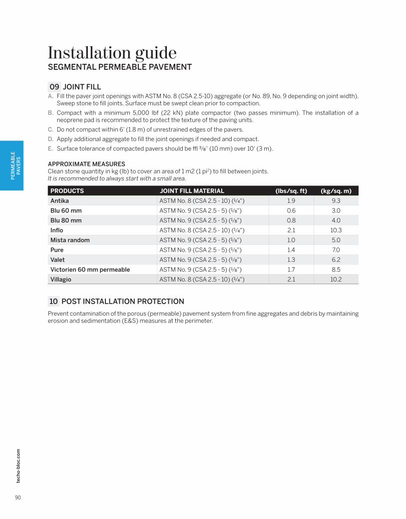
09 JOINT FILLA. Fill the paver joint openings with ASTM No. 8 (CSA 2.5-10) aggregate (or No. 89, No. 9 depending on joint width).
Sweep stone to fill joints. Surface must be swept clean prior to compaction.
B. Compact with a minimum 5,000 lbf (22 kN) plate compactor (two passes minimum). The installation of a neoprene pad is recommended to protect the texture of the paving units.
C. Do not compact within 6' (1.8 m) of unrestrained edges of the pavers.
D. Apply additional aggregate to fill the joint openings if needed and compact.
E. Surface tolerance of compacted pavers should be ± 3⁄8" (10 mm) over 10' (3 m).
APPROXIMATE MEASURESClean stone quantity in kg (lb) to cover an area of 1 m2 (1 pi2) to fill between joints.It is recommended to always start with a small area.
PRODUCTS JOINT FILL MATERIAL (lbs/sq. ft) (kg/sq. m)
Antika ASTM No. 8 (CSA 2.5 - 10) (1⁄4") 1.9 9.3
Blu 60 mm ASTM No. 9 (CSA 2.5 - 5) (1⁄8") 0.6 3.0
Blu 80 mm ASTM No. 9 (CSA 2.5 - 5) (1⁄8") 0.8 4.0
Inflo ASTM No. 8 (CSA 2.5 - 10) (1⁄4") 2.1 10.3
Mista random ASTM No. 9 (CSA 2.5 - 5) (1⁄8") 1.0 5.0
Pure ASTM No. 9 (CSA 2.5 - 5) (1⁄8") 1.4 7.0
Valet ASTM No. 9 (CSA 2.5 - 5) (1⁄8") 1.3 6.2
Victorien 60 mm permeable ASTM No. 9 (CSA 2.5 - 5) (1⁄8") 1.7 8.5
Villagio ASTM No. 8 (CSA 2.5 - 10) (1⁄4") 2.1 10.2
10 POST INSTALLATION PROTECTION
Prevent contamination of the porous (permeable) pavement system from fine aggregates and debris by maintaining erosion and sedimentation (E&S) measures at the perimeter.
SEGMENTAL PERMEABLE PAVEMENT

91
tech
o-b
loc.
com
Installation guide
PE
RM
EA
BLE
PA
VE
RS
SEGMENTAL PERMEABLE PAVEMENT – NO INFILTRATION
Typical cross section
SEGMENTAL PERMEABLE PAVEMENT – PARTIAL INFILTRATION
Typical cross section
A. PERMEABLE PAVER FROM TECHO-BLOC
B. JOINT FILLING MATERIAL ASTM No 8 (CSA 2.5-10 mm) AGGREGATE
C. BEDDING COURSE 1 1⁄2'' to 2'' (40 to 50 mm)ASTM No 8 (CSA 2.5-10 mm) AGGREGATE
D. BASE COURSE 4'' (100 mm) ASTM No 57 (CSA 5-28 mm) AGGREGATE
E. SUBBASE COURSE ASTM No 2 (CSA 40-80 mm) AGGREGATE
F. IMPERMEABLE MEMBRANE
G. SUBGRADE
H. CONCRETE EDGE
I. PERFORATED DRAIN CONNECTED TO DRAINAGE SYSTEM
A. PERMEABLE PAVER FROM TECHO-BLOC
B. JOINT FILLING MATERIAL ASTM No 8 (CSA 2.5-10 mm) AGGREGATE
C. BEDDING COURSE 1 1⁄2'' to 2'' (40 to 50 mm)ASTM No 8 (CSA 2.5-10 mm) AGGREGATE
D. BASE COURSE 4'' (100 mm) ASTM No 57 (CSA 5-28 mm) AGGREGATE
E. SUBBASE COURSE ASTM No 2 (CSA 40-80 mm) AGGREGATE
F. GEOTEXTILE
G. SUBGRADE
H. CONCRETE EDGE
SEGMENTAL PERMEABLE PAVEMENT – FULL INFILTRATIONTypical cross section
SEGMENTAL PERMEABLE PAVEMENT