PAVEMENT ANALYSIS AND DESIGN (ELECTIVE-II)...5.1 HIGHWAY PAVEMENT DESIGN: FLEXIBLE: NORTH DAKOTA...
12
ANJUMAN COLLEGE OF ENGINEERING & TECHNOLOGY MANGALWARI BAZAAR ROAD, SADAR, NAGPUR - 440001. DEPARTMENT OF CIVIL ENGINEERING Prof. Rashmi G. Bade, Department of Civil Engineering, Pavement Analysis & Design 1 PAVEMENT ANALYSIS AND DESIGN (ELECTIVE-II) B.E. EIGHT SEMESTER
Transcript of PAVEMENT ANALYSIS AND DESIGN (ELECTIVE-II)...5.1 HIGHWAY PAVEMENT DESIGN: FLEXIBLE: NORTH DAKOTA...

ANJUMAN COLLEGE OF ENGINEERING & TECHNOLOGY
MANGALWARI BAZAAR ROAD, SADAR, NAGPUR - 440001.
DEPARTMENT OF CIVIL ENGINEERING
Prof. Rashmi G. Bade, Department of Civil Engineering, Pavement Analysis & Design 1
PAVEMENT ANALYSIS AND DESIGN
(ELECTIVE-II)
B.E. EIGHT SEMESTER

ANJUMAN COLLEGE OF ENGINEERING & TECHNOLOGY
MANGALWARI BAZAAR ROAD, SADAR, NAGPUR - 440001.
DEPARTMENT OF CIVIL ENGINEERING
Prof. Rashmi G. Bade, Department of Civil Engineering, Pavement Analysis & Design 2
UNIT – 3 5) Highway pavement design: Flexible: North Dakota cone, CBR, IRC-37, Burmister, Triaxial
(Kansas), AASHTO method of design.
6) Airfield pavement design.

ANJUMAN COLLEGE OF ENGINEERING & TECHNOLOGY
MANGALWARI BAZAAR ROAD, SADAR, NAGPUR - 440001.
DEPARTMENT OF CIVIL ENGINEERING
Prof. Rashmi G. Bade, Department of Civil Engineering, Pavement Analysis & Design 3
5.1 HIGHWAY PAVEMENT DESIGN: FLEXIBLE: NORTH DAKOTA CONE
This method, similar to the CBR method, has been developed by the North Dakota State
Highway Department. The method consists in finding out the in-situ bearing power of the sub –
grade by means of a cone penetrometer, of the North Dakota Cone apparatus. The thickness is then
found from the design curve.
The penetrometer (or North Dakota cone apparatus) consists essentially of a shaft with a
sharp cone (half angle = 7045’) attached to one end. The movement of the shaft into the soil is
measured with the help of a vernier. The shaft can be locked to the frame when necessary. A disc is
fixed to the top of the shaft, over which weights can be fixed. The load carried by the shaft, during
penetration into the soil, divided by the area of the cone at the surface level is termed as the cone
bearing value qc.
Where qc = bearing value (kg/cm2)
Q = load on cone (kg)
= penetration (corrected) of cone (cm)
Fig. 1. North Dakota Curve.
The loads Q used in the test are 4.5, 9, 18 and 36 kg, inclusive of the weight of the shaft and
cone. Theoretically, neglecting friction, the penetration under 4.5 kg is half the penetration under 18
kg. Actually, it is never so, because of the rounding of the tip of the cone. A correction is, therefore,
added to or subtracted from all the readings so that the penetration 9 under 9 kg becomes half of the
penetration 36 under 36 kg.

ANJUMAN COLLEGE OF ENGINEERING & TECHNOLOGY
MANGALWARI BAZAAR ROAD, SADAR, NAGPUR - 440001.
DEPARTMENT OF CIVIL ENGINEERING
Prof. Rashmi G. Bade, Department of Civil Engineering, Pavement Analysis & Design 4
5.2 CALIFORNIA BEARING RATIO METHOD
In this method, the CBR values are used to determine the total thickness of the flexible
pavement and the thickness of various layers. Fig. 1.8 gives the design curves for different wheel
loads and traffic conditions.
The design curves are based on the data collected on a large number of pavements which
performed satisfactorily. The curves give the required thickness of construction above a material of a
certain CBR value. As it is evident, the required thickness of co nstruction above a material
decreases as the CBR value increases.
The Indian Road Congress (IRC) has recommended the design chart. The chart is similar to one
usedin U.K. The soaked CBR value of the subgrade is evaluated and the volume of the traffic is
estimated. The total thickness of the pavement is determined using the appropriate curve. Likewise,
the CBR value of the sub-base material is used to determine the thickness of construction over the
material. The thickness of the sub-base is equal to the total thickness of above the subgrade minus
the thickness of construction above the sub-base. Likewise, the thickness of the base is determined.
The CBR method is based on strength parameter of the material and is, therefore, more
rational than the group index method. The basic assumption in the method is that a layer of pavement
is of pavement is of superior quality than the layer below it. The shortcoming of the method is that it
gives the same total thickness above a material irrespective of the quality of the overlying layers.
Fig. 2.
ANJUMAN COLLEGE OF ENGINEERING & TECHNOLOGY
MANGALWARI BAZAAR ROAD, SADAR, NAGPUR - 440001.
DEPARTMENT OF CIVIL ENGINEERING
Prof. Rashmi G. Bade, Department of Civil Engineering, Pavement Analysis & Design 5
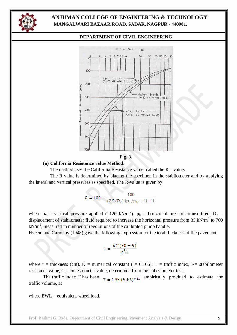
Fig. 3.
(a) California Resistance value Method:
The method uses the California Resistance value, called the R – value.
The R-value is determined by placing the specimen in the stabilometer and by applying
the lateral and vertical pressures as specified. The R-value is given by
where pv = vertical pressure applied (1120 kN/m2), ph = horizontal pressure transmitted, D2 =
displacement of stabilometer fluid required to increase the horizontal pressure from 35 kN/m2 to 700
kN/m2, measured in number of revolutions of the calibrated pump handle.
Hveem and Carmany (1948) gave the following expression for the total thickness of the pavement.
where t = thickness (cm), K = numerical constant ( = 0.166), T = traffic index, R= stabilometer
resistance value, C = cohesiometer value, determined from the cohesiometer test.
The traffic index T has been empirically provided to estimate the
traffic volume, as
where EWL = equivalent wheel load.
ANJUMAN COLLEGE OF ENGINEERING & TECHNOLOGY
MANGALWARI BAZAAR ROAD, SADAR, NAGPUR - 440001.
DEPARTMENT OF CIVIL ENGINEERING
Prof. Rashmi G. Bade, Department of Civil Engineering, Pavement Analysis & Design 6
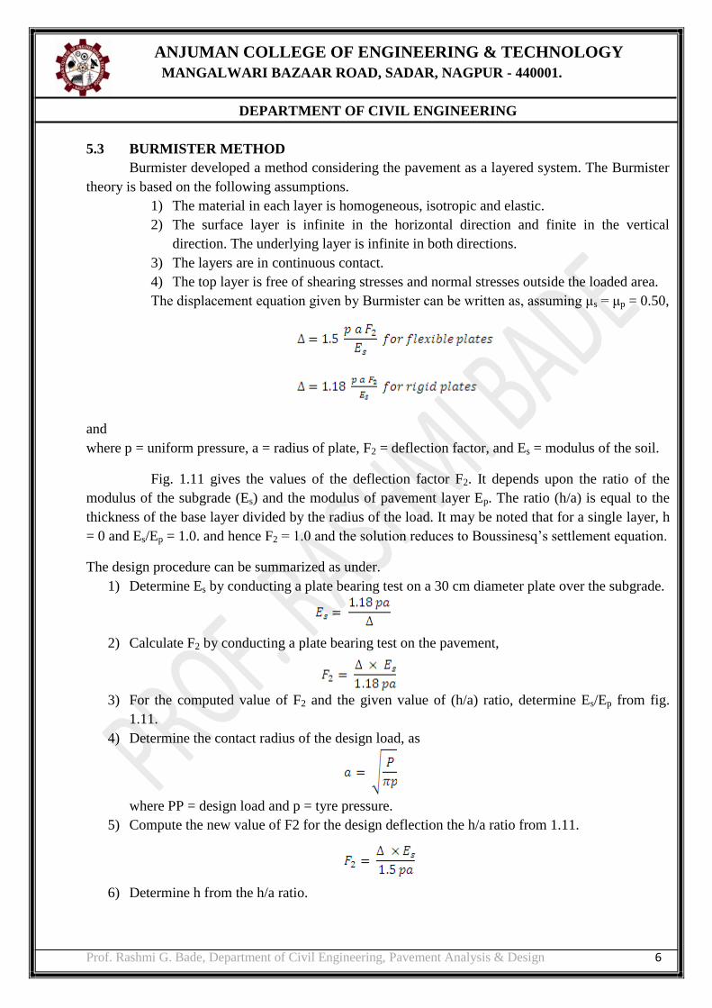
5.3 BURMISTER METHOD
Burmister developed a method considering the pavement as a layered system. The Burmister
theory is based on the following assumptions.
1) The material in each layer is homogeneous, isotropic and elastic.
2) The surface layer is infinite in the horizontal direction and finite in the vertical
direction. The underlying layer is infinite in both directions.
3) The layers are in continuous contact.
4) The top layer is free of shearing stresses and normal stresses outside the loaded area.
The displacement equation given by Burmister can be written as, assuming μs = μp = 0.50,
and
where p = uniform pressure, a = radius of plate, F2 = deflection factor, and Es = modulus of the soil.
Fig. 1.11 gives the values of the deflection factor F2. It depends upon the ratio of the
modulus of the subgrade (Es) and the modulus of pavement layer Ep. The ratio (h/a) is equal to the
thickness of the base layer divided by the radius of the load. It may be noted that for a single layer, h
= 0 and Es/Ep = 1.0. and hence F2 = 1.0 and the solution reduces to Boussinesq’s settlement equation.
The design procedure can be summarized as under.
1) Determine Es by conducting a plate bearing test on a 30 cm diameter plate over the subgrade.
2) Calculate F2 by conducting a plate bearing test on the pavement,
3) For the computed value of F2 and the given value of (h/a) ratio, determine Es/Ep from fig.
1.11.
4) Determine the contact radius of the design load, as
where PP = design load and p = tyre pressure.
5) Compute the new value of F2 for the design deflection the h/a ratio from 1.11.
6) Determine h from the h/a ratio.

ANJUMAN COLLEGE OF ENGINEERING & TECHNOLOGY
MANGALWARI BAZAAR ROAD, SADAR, NAGPUR - 440001.
DEPARTMENT OF CIVIL ENGINEERING
Prof. Rashmi G. Bade, Department of Civil Engineering, Pavement Analysis & Design 7
Fig. 4
5.4 TRIAXIAL TEST METHOD
The triaxial test is used to determine the shear strength of soil.
The triaxial test method for the design of flexible pavement is based on the Boussinesq’s
concept for homogeneous elastic single layer.
According to Boussinesq’s concept
According to triaxial test method it is
where,
T = Pavement thickness, (cm),
P = wheel load (Kg)
Es = modulus of elasticity of subgrade from triaxial test results (Kg/cm2)
A = radius of contact (cm)
s = design deflection
The triaxial compression teat is conducted on a soil specimen under a lateral pressure of 140
kN/m2 and the value of the modulus of elasticity is determined from the stress-strain curve.
The thickness of the pavement in cm can be determined using the formula given by the
Kansas Highway Dept.
where P = wheel load (kN), E = modulus of elasticity (kN/cm2), x = traffic coefficient (0.5 to 2.0), y
= saturation coefficient (= 0.5 to 1.0), a = area of contact (cm2), Δ = design deflection (= 0.25 cm).
If pavement and subgrade are considered as two layers, then stiffness factor will be (Es/Ep)1/3

ANJUMAN COLLEGE OF ENGINEERING & TECHNOLOGY
MANGALWARI BAZAAR ROAD, SADAR, NAGPUR - 440001.
DEPARTMENT OF CIVIL ENGINEERING
Prof. Rashmi G. Bade, Department of Civil Engineering, Pavement Analysis & Design 8
The pavement thickness is modified for the stiffness factor. Then pavement thickness is given
by
The relation between pavement layers of thickness t1 and t2 and modulus of elasticity E1 and E2 is
given by
5.5 AASHO SUB GRADE SOIL CLASSIFICATION
AASHO (American Association of State Highway Officials): In this method of classification
soils are classified into seven groups. A1 to A7. A1, A2, and A3 are granular soil with percentage
passing No.200 (75 μ) sieve less than 35 %. A4 to A7 soils are fine grained or silty clay soils with
percentage passing NO. 200 (75μ) sieve more than 35%. A1 soil are well graded, mixture of stone,
gravel, coarse sand, fine sand and non-plastic or slightly plastic soils binder. The soils of this group
are subdivided into !-1-a and A-1-b.
A-1-a = consists of stone fragments or gravels
A-1-b = consists of coarse sand.
A2 soils include a wide range of granular soils ranging from A1 to A3 groups with 35% fines form
A4, A5, A6, A7 groups. So based on fines contents, the soils of A2 groups are sub-divided into
subgroups A-2-4, A-2-5,A-2-6, and A-2-7.
A3 soils consist of uniformly graded medium or fine sand similar to beach sand or desert blown
sand. Poorly graded fine sand of stream deposits with some coarse sand and gravel are also included
in this group.
A4 soils are silty soils, non-plastic or moderately plastic in nature with liquid limit and plasticity
index valued less than 40 and 10 respectively.
A5 soils are also silty soils with plasticity index less than 10% but with liquid limit greater than 40%.
These include highly compressible or elastic soils.
A6 soils are plastic clays, having high values of plasticity. Index greater than 10% and low values of
liquid limit below 40%. They have high volume change properties with moisture content.
A7 soils are also cloyed soils but values of liquid and plastic limits are high. These soils have low
permeability.
The AASHO design procedure [AASHO, 1993] was developed based on the findings of the
AASHO road test [Highway Research Board, 1962]. Following parameters are required for design.
a) Resilient modulus for the subgrade.
b) Cumulative ESAL’s for the design life of the pavement.
c) Drainage coefficient for unbound material.
d) Reliability level.
e) Overall standard deviation.
f) Serviceability.
g) Modulus of subgrade reaction.
h) Elastic modulus of concrete.
i) Modulus of rupture of concrete.
j) Load transfer factors.
ANJUMAN COLLEGE OF ENGINEERING & TECHNOLOGY
MANGALWARI BAZAAR ROAD, SADAR, NAGPUR - 440001.
DEPARTMENT OF CIVIL ENGINEERING
Prof. Rashmi G. Bade, Department of Civil Engineering, Pavement Analysis & Design 9
The parameters used in AASHTO method are :-
a) CBR.
b) Resiliency factor.
c) Traffic in terms of ESAL.
d) Thickness equivalency factor.
These parameters yield a structural number or total thickness of pavements. The determination of the
individual layer thickness is achieved using the thickness equivalent factor and the most practical
layer for construction.
AASHO GUIDE
The 1986-1993 AASHO guide made many modifications in the procedures. The principle
modification to AASHO concrete pavement design are: -
a) Drainage Coefficient: - To allow for changes in thickness requirement due to differences in
drainage properties, pavement layers, and subgrade, a drainage coefficient Cd was included in
the design. Setting Cd = 1 for conditions at the AASHO road test. The percentage of time
during the year that the pavement structure would be exposed to moisture levels approaching
saturation can be estimated from the annual rainfall and the prevailing drainage condition.
b) Determination of the design K- value as a function of subgrade resilient modulus, rigid layer,
base thickness and elastic modulus erodability and seasonal variation in soil.
c) Load Transfer Coefficient: - Load transfer coefficient J is a numerical index developed from
experience and stress analysis. Addition of corner stress adjustment 1-factor values as a
function of pavement joint, load transfer, shoulder type.
a) A reliability adjustment applied to the design ESAL input instead of using a factor of safety
on the modulus of rupture.
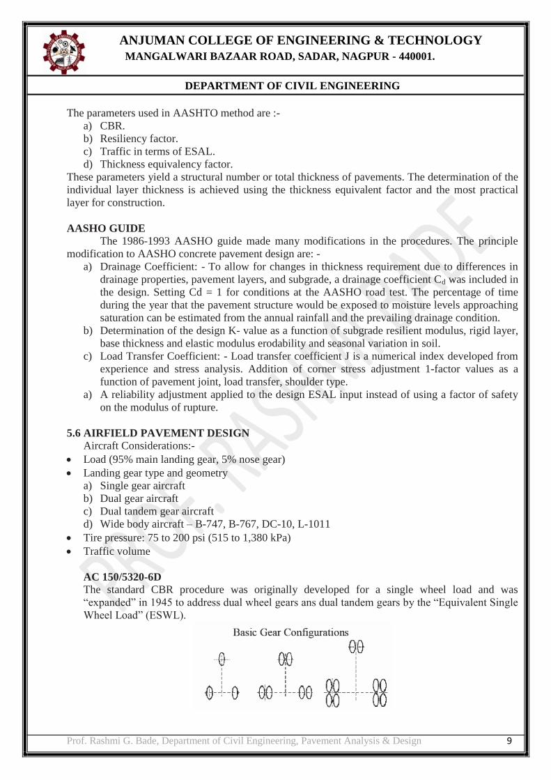
5.6 AIRFIELD PAVEMENT DESIGN
Aircraft Considerations:-
Load (95% main landing gear, 5% nose gear)
Landing gear type and geometry
a) Single gear aircraft
b) Dual gear aircraft
c) Dual tandem gear aircraft
d) Wide body aircraft – B-747, B-767, DC-10, L-1011
Tire pressure: 75 to 200 psi (515 to 1,380 kPa)
Traffic volume
AC 150/5320-6D
The standard CBR procedure was originally developed for a single wheel load and was
“expanded” in 1945 to address dual wheel gears ans dual tandem gears by the “Equivalent Single
Wheel Load” (ESWL).
ANJUMAN COLLEGE OF ENGINEERING & TECHNOLOGY
MANGALWARI BAZAAR ROAD, SADAR, NAGPUR - 440001.
DEPARTMENT OF CIVIL ENGINEERING
Prof. Rashmi G. Bade, Department of Civil Engineering, Pavement Analysis & Design 10
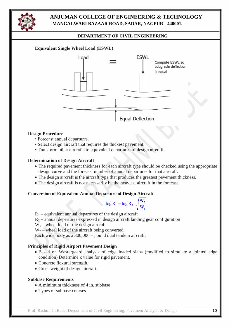
Equivalent Single Wheel Load (ESWL)
Design Procedure
• Forecast annual departures.
• Select design aircraft that requires the thickest pavement.
• Transform other aircrafts to equivalent departures of design aircraft.
Determination of Design Aircraft
The required pavement thickness for each aircraft type should be checked using the appropriate
design curve and the forecast number of annual departures for that aircraft.
The design aircraft is the aircraft type that produces the greatest pavement thickness.
The design aircraft is not necessarily be the heaviest aircraft in the forecast.
Conversion of Equivalent Annual Departure of Design Aircraft
R1 – equivalent annual departures of the design aircraft
R2 – annual departures expressed in design aircraft landing gear configuration
W1 – wheel load of the design aircraft
W2 – wheel load of the aircraft being converted.
Each wide body as a 300,000 – pound dual tandem aircraft.
Principles of Rigid Airport Pavement Design
Based on Westergaard analysis of edge loaded slabs (modified to simulate a jointed edge
condition) Determine k value for rigid pavement.
Concrete flexural strength.
Gross weight of design aircraft.
Subbase Requirements
A minimum thickness of 4 in. subbase
Types of subbase courses

ANJUMAN COLLEGE OF ENGINEERING & TECHNOLOGY
MANGALWARI BAZAAR ROAD, SADAR, NAGPUR - 440001.
DEPARTMENT OF CIVIL ENGINEERING
Prof. Rashmi G. Bade, Department of Civil Engineering, Pavement Analysis & Design 11
- Item P-154: subbase course
- Item P-208: aggregate base course
- Item P-209: crushed aggregate base course
- Item P-211: lime rock base course
- Item P-304: cement treated base course - Item P-306: econocrete subbase course
- Item P-401: plant mix bituminous pavements Stabilized subbase (aircraft weight > 100,000
lbs)
- Item P-304: cement treated base course
- Item P-306: econocrete subbase course - Item P-401: plant mix bituminous pavement
Concrete Flexural Strength
Design strength of 600 to 650 psi is recommended for most airfield applications.
Strength at 28 days.
5% less than the test strength used for thickness design.
Effect of Subbase on K
- Well-Graded Crushed Aggregate.
Effect of Subbase on K
- Bank-Run Sand & Gravel (PI<6)

ANJUMAN COLLEGE OF ENGINEERING & TECHNOLOGY
MANGALWARI BAZAAR ROAD, SADAR, NAGPUR - 440001.
DEPARTMENT OF CIVIL ENGINEERING
Prof. Rashmi G. Bade, Department of Civil Engineering, Pavement Analysis & Design 12
Effect of Subbase on K
- Stabilized Subbase