Passive and active acoustics using an … Bingham...Bingham et al.: Passive and Active Acoustics...
13
Passive and Active Acoustics Using an Autonomous Wave Glider • • • • • • • • • • • • • • • • • • • • • • • • • • • • • • • • • • • • Brian Bingham and Nicholas Kraus Department of Mechanical Engineering, University of Hawaii at Manoa, Honolulu, Hawaii 96822 e-mail: [email protected], [email protected] Bruce Howe Department of Ocean and Resources Engineering, University of Hawaii at Manoa, Honolulu, Hawaii 96822 e-mail: [email protected] Lee Freitag, Keenan Ball, Peter Koski, and Eric Gallimore Department of Applied Ocean, Physics and Engineering, Woods Hole Oceanographic Institution, Woods Hole, Massachusetts 02543 e-mail: [email protected], [email protected], [email protected], [email protected] Received 9 September 2011; accepted 22 February 2012 The recently developed wave glider has the potential to be an effective unmanned platform for acoustic ap- plications. We present the results of a variety of experiments that quantify this potential. The radiated self- noise of the autonomous platform is evaluated using an integrated passive acoustic recorder during a set of field trials off the coast of Hawaii. We present the radiated noise spectra from these trials to illustrate the dependence on hydrophone location and sea state. Using the same instrumentation, we demonstrate the ability of a modified wave glider to detect marine mammals using passive acoustic monitoring techniques. We also evaluate the performance of the wave glider operating as an active acoustic gateway, highlighting the potential of this platform to serve as a navigation reference and communications relay for scientific, in- dustrial, and military subsea assets. To demonstrate the potential of the wave glider platform to support acoustic navigation, we assess the performance of time-of-flight range estimation and seafloor transponder localization. These tests were performed using commercial off-the-shelf acoustic positioning hardware in- tegrated with the wave glider to illustrate that the low self-noise of the wave glider makes it possible to achieve acoustic positioning performance similar to previously reported results. Finally, we show that the glider can operate as a station-keeping surface communications gateway and provide recommendations for its use. C 2012 Wiley Periodicals, Inc. 1. INTRODUCTION Exploring, understanding, and monitoring the marine en- vironment are fundamentally limited by our ability to transmit signals through the ocean acoustic channel. The ocean is essentially opaque to electromagnetic waves, but sound waves can travel long distances with relatively low attenuation. For this reason, acoustic instruments are a fun- damental component in many marine operations. Robotic vehicles serve in an increasing variety of roles for scientific, industrial, and military endeavors. Many of these platforms, such as remotely operated vehicles (ROVs) and autonomous underwater vehicles (AUVs) (or unmanned underwater vehicles (UUVs)), have reached a sufficiently high level of maturity to be considered com- mercial off-the-shelf assets. Recently a new type of vehicle has emerged. Developed by Liquid Robotics, Inc. (LRI), the Direct correspondence to: Brian Bingham, e-mail: [email protected]. wave glider is a wave-propelled unmanned surface vessel (USV) that is capable of long-duration deployments of a year or more. Many of the potential applications for this novel plat- form involve passive and active acoustics. For example, passive monitoring has been shown to be an effective tool for understanding marine mammals and monitoring ship traffic (as well as a variety of military applications). Cur- rently these passive systems are often moored near the seafloor or towed by surface ships. As a platform for pas- sive monitoring the wave glider provides distinct advan- tages; it is mobile, provides ample solar power for per- sistent deployments, emits very little acoustic energy to interfere with incoming sound, provides real-time access to collected observations, and operates autonomously, elimi- nating the expense of a surface ship. Active acoustics also plays an important role in ma- rine operations, especially navigation and communication. A pervasive limitation of acoustic navigation has been the Journal of Field Robotics 29(6), 911–923 (2012) C 2012 Wiley Periodicals, Inc. View this article online at wileyonlinelibrary.com • DOI: 10.1002/rob.21424
Transcript of Passive and active acoustics using an … Bingham...Bingham et al.: Passive and Active Acoustics...
Passive and Active Acoustics Using an AutonomousWave Glider
• • • • • • • • • • • • • • • • • • • • • • • • • • • • • • • • • • • •
Brian Bingham and Nicholas KrausDepartment of Mechanical Engineering, University of Hawaii at Manoa, Honolulu, Hawaii 96822e-mail: [email protected], [email protected] HoweDepartment of Ocean and Resources Engineering, University of Hawaii at Manoa, Honolulu, Hawaii 96822e-mail: [email protected] Freitag, Keenan Ball, Peter Koski, and Eric GallimoreDepartment of Applied Ocean, Physics and Engineering, Woods Hole Oceanographic Institution, Woods Hole,Massachusetts 02543e-mail: [email protected], [email protected], [email protected], [email protected]
Received 9 September 2011; accepted 22 February 2012
The recently developed wave glider has the potential to be an effective unmanned platform for acoustic ap-plications. We present the results of a variety of experiments that quantify this potential. The radiated self-noise of the autonomous platform is evaluated using an integrated passive acoustic recorder during a setof field trials off the coast of Hawaii. We present the radiated noise spectra from these trials to illustratethe dependence on hydrophone location and sea state. Using the same instrumentation, we demonstrate theability of a modified wave glider to detect marine mammals using passive acoustic monitoring techniques.We also evaluate the performance of the wave glider operating as an active acoustic gateway, highlightingthe potential of this platform to serve as a navigation reference and communications relay for scientific, in-dustrial, and military subsea assets. To demonstrate the potential of the wave glider platform to supportacoustic navigation, we assess the performance of time-of-flight range estimation and seafloor transponderlocalization. These tests were performed using commercial off-the-shelf acoustic positioning hardware in-tegrated with the wave glider to illustrate that the low self-noise of the wave glider makes it possible toachieve acoustic positioning performance similar to previously reported results. Finally, we show that theglider can operate as a station-keeping surface communications gateway and provide recommendations forits use. C© 2012 Wiley Periodicals, Inc.
1. INTRODUCTION
Exploring, understanding, and monitoring the marine en-vironment are fundamentally limited by our ability totransmit signals through the ocean acoustic channel. Theocean is essentially opaque to electromagnetic waves, butsound waves can travel long distances with relatively lowattenuation. For this reason, acoustic instruments are a fun-damental component in many marine operations.
Robotic vehicles serve in an increasing variety of rolesfor scientific, industrial, and military endeavors. Manyof these platforms, such as remotely operated vehicles(ROVs) and autonomous underwater vehicles (AUVs) (orunmanned underwater vehicles (UUVs)), have reached asufficiently high level of maturity to be considered com-mercial off-the-shelf assets. Recently a new type of vehiclehas emerged. Developed by Liquid Robotics, Inc. (LRI), the
Direct correspondence to: Brian Bingham, e-mail: [email protected].
wave glider is a wave-propelled unmanned surface vessel(USV) that is capable of long-duration deployments of ayear or more.
Many of the potential applications for this novel plat-form involve passive and active acoustics. For example,passive monitoring has been shown to be an effective toolfor understanding marine mammals and monitoring shiptraffic (as well as a variety of military applications). Cur-rently these passive systems are often moored near theseafloor or towed by surface ships. As a platform for pas-sive monitoring the wave glider provides distinct advan-tages; it is mobile, provides ample solar power for per-sistent deployments, emits very little acoustic energy tointerfere with incoming sound, provides real-time access tocollected observations, and operates autonomously, elimi-nating the expense of a surface ship.
Active acoustics also plays an important role in ma-rine operations, especially navigation and communication.A pervasive limitation of acoustic navigation has been the
Journal of Field Robotics 29(6), 911–923 (2012) C© 2012 Wiley Periodicals, Inc.View this article online at wileyonlinelibrary.com • DOI: 10.1002/rob.21424
912 • Journal of Field Robotics—2012
need for fixed transponders on the seafloor. The waveglider has the potential to provide a more flexible, mobilesolution without the need for a dedicated surface ship. Forexample, a wave glider, augmented with acoustic naviga-tion and communication instruments, could serve as a nav-igation gateway for one or multiple AUVs (either poweredvehicles or underwater gliders). A set of wave gliders couldprovide the same functionality as GPS satellite vehicles,providing absolute position updates (albeit spatially lim-ited by acoustic propagation).
This article describes the application of this new classof USV to support active and passive acoustic functions. Be-cause of the relatively recent emergence of this tool, manyof its capabilities (and limitations) are still in question. Wedescribe the results of experiments and analysis to quantifythe performance of this new platform for acoustic applica-tions. The goals of this work are as follows:
• Quantify the acoustic signature of the wave glider• Evaluate the performance of the wave glider as a plat-
form for passive acoustic monitoring• Demonstrate active acoustic ranging and evaluate the
potential of the wave glider as an acoustic navigationgateway to support underwater localization
• Test the ability of a modified wave glider to preciselylocalize seafloor instrumentation
• Demonstrate acoustic communication between theglider and seafloor instrumentation
2. BACKGROUND AND CLOSELY RELATED WORK
2.1. The Wave Glider
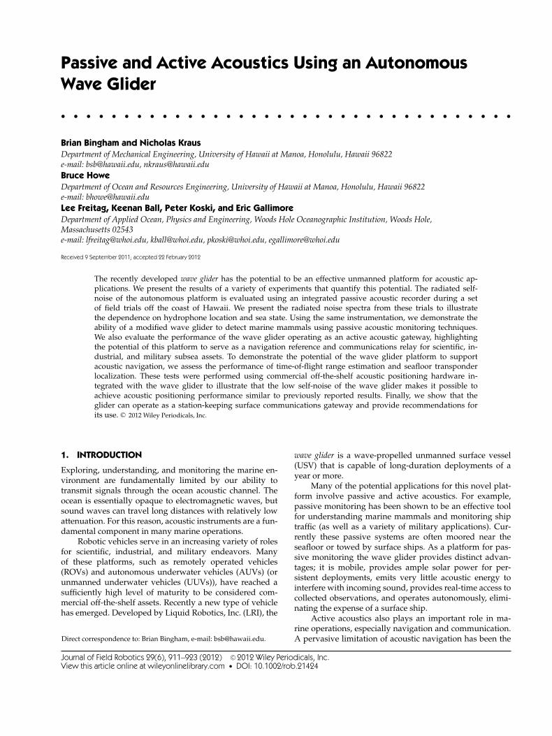
The wave glider is a new class of wave-propelled, persis-tent, unmanned ocean vehicle. The key innovation of thewave glider is its ability to harvest the abundant energyin ocean waves to provide essentially limitless propulsion(Hine, Willcox, Hine, & Richardson, 2009). As illustrated inFigure 1, the wave glider is composed of a submerged gliderattached via an umbilical to a surface float and is propelledby the conversion of ocean wave energy (differential verti-cal motion) into forward thrust, independent of wave direc-tion. In this article we refer to the two-body system in thefollowing way: the surface body is the float; the submergedbody is the glider; and the complete vehicle is the waveglider. Except for the energy required to quasi-statically ad-just rudder position, the wave energy propulsion system ispurely mechanical. Using this propulsion system, the waveglider can maintain a typical forward speed of 0.75 m/s(1.5 kts) in seas as small as 0.5–1.0 m wave height (Willcoxet al., 2009).
2.2. Passive Acoustic Monitoring
One anticipated application of the wave glider platformis passive acoustic monitoring of marine mammals. Tradi-tionally, visual surveys have been used to monitor marine
Figure 1. Model of the Liquid Robotics, Inc. wave glider withannotations to highlight the major subsystems. The forwardand aft solar panels are shown on top of the float; the payloadinstrument housings are located underneath each solar panel.
mammal behavior. These surveys are limited because ob-servers can only see animals during the short time they areat the surface and these surveys can only be conducted dur-ing daylight hours in relatively good weather (Mellinger,Stafford, Moore, Dziak, & Matsumoto, 2007). Because ofthese shortcomings, passive acoustic monitoring—usinghydrophones at fixed locations or on moving platforms—has become a standard method for detecting, classifying,and localizing marine mammals. Stationary hydrophonesenable continuous sampling for complete temporal cover-age, but with limited spatial coverage. In contrast, ship-towed hydrophones can achieve large spatial coverage, butthe monitoring duration (temporal coverage) is limited bythe high operational cost of research vessels and surfaceships (Mellinger & Barlow, 2003).
More recently, the community has realized the poten-tial for robotic platforms to provide a mobile, persistent,low-cost monitoring capability to achieve both temporaland spatial coverage. Underwater gliders have been thefocus of much of this work. Acoustic recorders integratedinto the Seaglider (iRobot Corporation) were deployed in2006 to monitor a variety of cetacean species in MontereyBay, California (Moore, Howe, Stafford, & Boyd, 2008). Dur-ing other deployments, the same system recorded transmis-sions from the 75-Hz Kauai acoustic thermometry of oceanclimate (ATOC) source located off Kauai, as well as navalsonars (Howe & Boyd, 2008). Similarly, a set of Slocumgliders (Teledyne Webb Research) was deployed in theGulf of Maine to study the feeding behavior of sei whales(Baumgartner & Fratantoni, 2008).
Unmanned surface vessels are likely to be the nextplatform for autonomous monitoring. The high-frequency
Journal of Field Robotics DOI 10.1002/rob
Bingham et al.: Passive and Active Acoustics Using an Autonomous Wave Glider • 913
acoustic recording package (HARP) system (Wiggins &Hildebrand, 2007) has been demonstrated aboard a waveglider for passive monitoring (Wiggins, Manley, Brager, &Woolhiser, 2010). Our experimental results expand on thisearlier report by providing sound-pressure-level estimatesfor a broader frequency range than previously reported.We also present an evaluation of the capabilities of thewave glider platform for active acoustic functions: naviga-tion and communication. Researchers have also proposedan autonomous sailboat for passive acoustic monitoringto address the speed and payload limitations of underwa-ter glider based solutions (Klinck, Stelzer, Jafarmadar, &Mellinger, 2009).
2.3. Active Acoustic Navigation
Underwater navigation has been a topic of research and de-velopment for more than four decades as military, indus-trial, and scientific applications have created the need formethods to precisely position underwater assets. This im-petus has led to a wide array of commercial off-the-shelfinstrumentation options as well as a variety of methodsfor combining these sensors into a complete navigation so-lution (see Kinsey, Eustice, & Whitcomb, 2006; Leonard,Bennett, Smith, & Feder, 1998; Stutters, Liu, Tiltman, &Brown, 2008) for review articles).
In long-baseline (LBL) acoustic positioning, a standardin underwater navigation, location is estimated via multi-lateration using distances measured acoustically from fixedtransponders. First used in the 1960s and 1970s (Hunt et al.,1974), acoustic transponders moored to the seafloor havebeen used to estimate the positions of a wide spectrum ofunderwater assets: submersibles, towed instrumentation,ROVs, and AUVs (Milne, 1983). The typical operation ofan LBL system (described in Whitcomb, Yoerger, Singh, &Mindell, 1998; Yoerger, Jakuba, Bradley, & Bingham, 2007)includes transponder deployment, sound-velocity profilemeasurement, transponder survey prior to subsea opera-tion, and transponder recovery after the operation comple-tion.
Many research efforts in underwater navigation seekto reduce (or remove) the role of seafloor-moored transpon-ders in a navigation solution or to eliminate the need tosurvey the deployed transponders from the surface—a pro-cess that consumes considerable operational time. One so-lution is to place the transponders at the surface on floatingbuoys so that constant position updates can be acquired viaGPS. This approach has been used for tracking. AUVs forsurvey operations (Austin, Stokey, & Sharp, 2000; Desset,Damus, Morash, & Bechaz, 2003) and for tracking of sub-merged acoustic arrays (Howe, Mercer, & Spindel, 1989). Itis important to distinguish tracking (determining the loca-tion of the mobile asset remotely in real time or throughpost-processing) from positioning (determining the locationin real time aboard the mobile asset for navigation). The ad-vantage of using a wave glider for this scenario, rather than
drifting buoys, is that the wave glider is mobile, allowing itto maintain position over the operational area or to coordi-nate its motion with the requirements of the subsea assets.
Using reliable acoustic communication to support nav-igation has generated new solutions, which continue to re-duce the dependence on acoustic transponders. With theability to transmit ephemeris data from a surface ship to thesubmerged platform, it becomes possible to eliminate thetransponders altogether and use the moving surface ship(with GPS navigation) as an absolute reference (Webster,Eustice, Singh, & Whitcomb, 2009; Eustice, Whitcomb,Singh, & Grund, 2007). A similar solution used poweredautonomous surface vehicles to provide a moving base-line for subsea navigation (Curcio et al., 2005; Vaganay,Leonard, Curcio, & Willcox, 2004). The Hugin AUV, a suc-cessful commercial survey tool, has used acoustic commu-nication to provide position updates and change the AUVmission from the surface (Vestgard, Storkersen, & Sortland,1999). The advantage of using a wave glider to providethis functionality is that it eliminates the need for a surfaceship, reducing the personnel and energy costs through theuse of a small, autonomous robot that can be deployed forlong-duration missions.
2.4. GPS/Acoustic Positioningof Subsea Instruments
Determining the absolute georeference position of instru-ments fixed to the seafloor is an important capabilityfor applications such as LBL positioning and seafloorgeodesy. For both these applications, the position ofmoored transponders is estimated by maneuvering the shiparound each transponder while repeatedly measuring thetime of flight of acoustic signals between the transponderand the ship-mounted transducer. This empirical measure-ment of the slant range is then compared with a predictionof the slant range, which is a function of the measured ship-mounted transducer position and the unknown transpon-der position. The transponder position can be estimated byminimizing the error between the acoustically measuredslant ranges and the predicted slant ranges.
As discussed earlier, the transponder survey is an im-portant preliminary step in LBL navigation; the accuracy ofthe navigation solution can only be as good as the georef-erenced locations of the transponders. Using off-the-shelfacoustic positioning transponders and the surface ship’sGPS position (typically P-code based) and heading, it ispossible to determine the position of each transponder towithin “just a few meters” (Whitcomb, et al., 1998). In a pre-vious work we found that the root-mean-squared residualresulting from surveying three transponders for use withan AUV ranged from 1.5 to 2.1 m using transponders (Tele-dyne Benthos, TR-6001) at 7–15 kHz with a 10-ms pulselength (Bingham et al., 2010).
Precise positions of seafloor-mounted transponderscan also be used to detect seafloor crustal movement in
Journal of Field Robotics DOI 10.1002/rob
914 • Journal of Field Robotics—2012
seismically active locations. This method was originallyimplemented by Spiess et al. (Spiess et al., 1998) usingcustom high-precision transponders with a timing resolu-tion of 10 μs (Spiess, Boegeman, Zimmerman, Chadwell, &Hildebrand). The resulting experiment demonstrated hor-izontal positioning repeatability (precision) of less than5 cm, where the center of a transponder array was esti-mated to infer crustal motion. Other studies have used sim-ilar methods combining high-precision ship-based GPS andacoustic range estimation to position transponders in ar-rays or as single units (Fujita et al., 2006; Obana, Katao, &Ando, 2000; Osada et al., 2003; Sweeney, Chadwell, Hilde-brand, & Spiess, 2005; Yamada et al., 2002). The experimen-tal results illustrate that the position of the seafloor instru-ments can be estimated with a repeatability of better than20 cm, with some reported precision values of better than5 cm. Furthermore, these high-precision techniques havebeen applied to AUV navigation to achieve an absolute ac-curacy of ±30 cm (Kussat & Chadwell, 2005). The limitingfactor in determining seafloor position with this level ofresolution is the lack of observability of the instantaneoussound velocity profile (Yamada et al., 2002). The results pre-sented in this article show that the wave glider has the po-tential to support positioning of subsea instruments, replac-ing (or augmenting) a dedicated surface ship to accomplishthe acoustic interrogation.
2.5. Supporting Acoustic Communication
Employing a wave glider as an acoustic communicationsgateway for either fixed or mobile undersea systems is alsoan attractive use of the energy-harvesting platform. The
most obvious application of the wave glider gateway is tosubstitute for fixed wireless buoys that link subsea acous-tic data with satellite telemetry. Examples include deep-ocean assessment and reporting of tsunamis (DART) buoys(Lawson et al., 2011; Meinig, Stalin, Nakamura, & Mil-burn, 2005) and buoy-based deep-water ocean observato-ries (Frye et al., 2005). Deep-ocean buoys are very expensiveand must be maintained regularly, whereas subsea instru-ments, once in place and equipped with sufficient power,can operate for several years. The station-keeping capabil-ity of the wave glider in most areas of the world (thoughnot all) is sufficient to keep it easily within 1 km of a desiredpoint on the ocean surface, meaning that coverage will becontinuous.
Use of the glider as a gateway for monitoring deep mo-bile systems is also possible, though the speed of the glideris less than that of most powered vehicles. However, forcertain types of surveys, in particular where a deep vehicleis driving on closely spaced track lines in a relatively smallarea, the wave glider can easily provide a link to shore ora nearby ship via the acoustic modem and radio or satellitelink.
3. EXPERIMENTAL SETUP
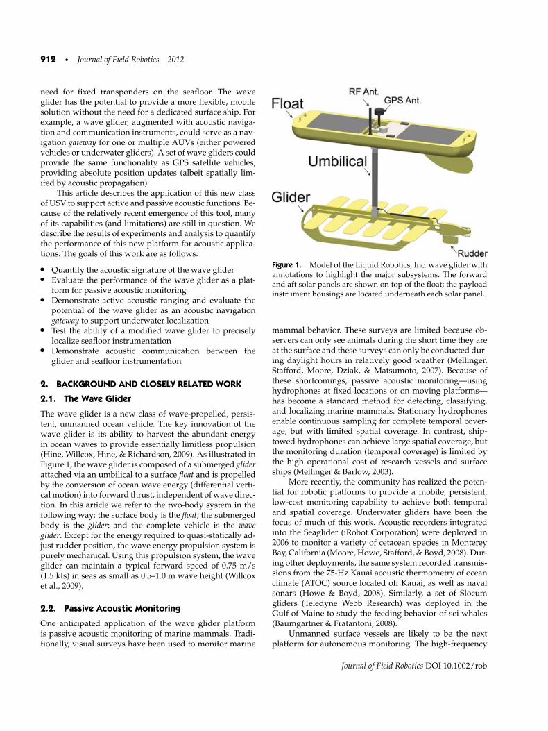
Two wave gliders were involved in these experiments. Onewas acquired and modified by the University of Hawaiiat Manoa (UHM), the other by the Woods Hole Oceano-graphic Insitution (WHOI). The UHM wave glider wasconfigured primarily for passive characterization and ac-tive navigation. The WHOI wave glider was configured foracoustic communication. Figure 2 shows the locations of
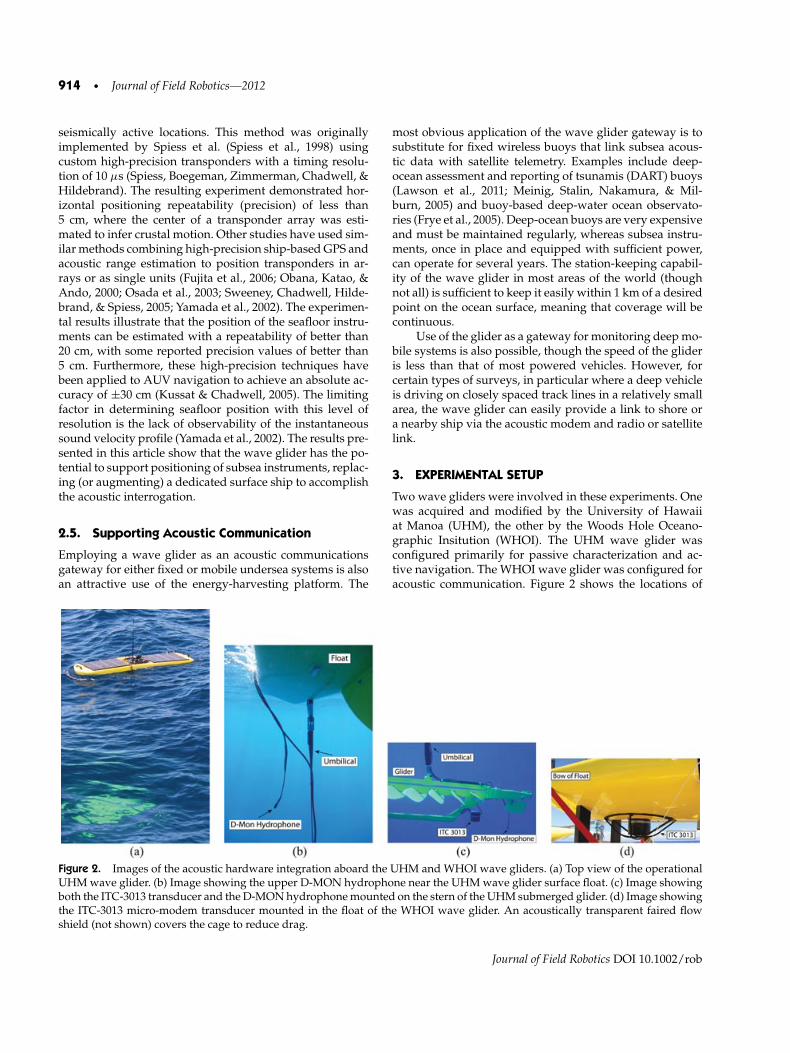
Figure 2. Images of the acoustic hardware integration aboard the UHM and WHOI wave gliders. (a) Top view of the operationalUHM wave glider. (b) Image showing the upper D-MON hydrophone near the UHM wave glider surface float. (c) Image showingboth the ITC-3013 transducer and the D-MON hydrophone mounted on the stern of the UHM submerged glider. (d) Image showingthe ITC-3013 micro-modem transducer mounted in the float of the WHOI wave glider. An acoustically transparent faired flowshield (not shown) covers the cage to reduce drag.
Journal of Field Robotics DOI 10.1002/rob
Bingham et al.: Passive and Active Acoustics Using an Autonomous Wave Glider • 915
the passive and active acoustic transducers aboard the twowave gliders.
3.1. The UHM Wave Glider
The UHM wave glider was augmented with a passiveacoustic recorder, an acoustic modem (for navigation andcommunication), and navigation aids to improve the po-sitioning of the vehicle. The D-MON passive recordingsystem was included to quantify the acoustic environ-ment near the wave glider and to evaluate the potentialof the wave glider for passive marine mammal monitor-ing. The D-MON was developed at WHOI to be capableof both high-fidelity passive acoustic monitoring and flexi-ble implementation of embedded real-time detection algo-rithms. Two D-MON hydrophones were added to the waveglider—one directly below the surface float and one at thestern of the subsurface glider (see Figures 2(b) and 2(c)).
A WHOI micro-modem (Freitag et al., 2005) was inte-grated into the UHM wave glider to support both acous-tic navigation and communication. An ITC-3013 acoustictransducer was used with the micro-modem. Based on theresults of the early D-MON recordings (described in Sec-tion 4), the transducer was mounted on the subsea glideras shown in Figure 2(c) to reduce the ambient noise.
It was also necessary to integrate navigation, teleme-try, and data-logging hardware to support the experimen-tal evaluation of passive and active acoustic performanceof the wave glider. We integrated a GPS receiver (Trim-ble ProXT and external antenna with sub-meter real-timeaccuracy) to improve the performance of the standard re-ceiver from LRI. We also integrated an inertial measure-ment unit (IMU) (Microstrain 3DM-GX2) to augment theGPS position and to directly measure the ocean conditionsat the wave glider. A line-of-sight wireless telemetry sys-tem(Freewave MM2-P-T Ethernet radio) was included toprovide a high-bandwidth connection between the waveglider and the base station located aboard the R/V KlausWyrtki. The onboard instrumentation data were archivedaboard the wave glider using an embedded single-boardcomputer.
The instruments were powered by a combinationof the wave glider’s solar panels (during the day) andonboard battery storage (during the night). The total powerconsumption for all the added instrumentation was 26 W.This total is dominated by the onboard processor includedfor the test (18 W). The wave glider included 665 Wh ofbattery capacity and two 43-Wh solar panels. The actualavailable power supplied by the panels depends greatly onthe local solar conditions. During our deployments the so-lar panels were able to fully change the batteries duringdaylight hours despite the additional power draw. Futurelong-duration deployments would require a more power-efficient processing solution, but, for the purposes of ourexperimental assessment, having a fully functional com-puting environment on board was advantageous.
3.2. The WHOI Wave Glider
On the WHOI wave glider the ITC-3013 transducer foracoustic communications was mounted on the undersideof the surface float. Integration of external sensors onthe wave glider, including acoustic transducers or hy-drophones, is challenging because of the need to minimizedrag. LRI has taken a significant amount of care to reducethe drag of all components of the glider, and previous workhad shown that, for example, large cables added to the um-bilical greatly reduced the ability of the wave glider to pro-pel itself through the ocean. Thus an important part of thedesign work was developing components that would addas little drag as possible.
As mentioned earlier, the WHOI wave glider is con-figured as a station-keeping acoustic communications gate-way buoy. Using information from a previous modem in-tegration with the wave glider (LRI internal report), wherethe transducer was embedded in the float to eliminate sig-nal reflections from the surface that were reducing reliabil-ity, the same approach was followed for the initial integra-tion on the WHOI wave glider, as shown in Figure 2(d).However, platform-generated noise was not measured inthe previous LRI work, and it was suspected that althougheliminating surface reflections was important, the noisefield near the float could also impact performance. Thus abroadband recorder was added to monitor the input to theacoustic modem for platform noise effects. During the testsdescribed in later sections, the modem and the recorderwere operated in parallel.
4. RESULTS OF PASSIVE ACOUSTIC OBSERVATIONS
Quantifying the acoustic signature of the wave glider is animportant aspect of evaluating the potential of the platformto support acoustic applications. Our hypothesis is that be-cause the vehicle has only one actively moving part (therudder) and passively moving wings, it will be an idealplatform for deploying sensitive passive monitoring instru-mentation.
The UHM wave glider, with the D-MON passiveacoustic recorder, was operated for six days between Febru-ary 24 and March 15, 2011 off the south coast of Oahu.The D-MON recorded two channels continuously duringoperations—one for the hydrophone below the float andone for the hydrophone located on the glider. As much aspossible, the research vessel used for deployment and re-covery was separated from the wave glider with the en-gine and generators turned off. The sea state during thetrials was generally calm, with larger swells on the lastday of operations (March 15). The wind and sea condi-tions during the pertinent operational days are describedin Table I. These observations are from NOAA’s on-shoreweather station (OOUH1) and the nearby NOAA data buoy(Station 51204).
Journal of Field Robotics DOI 10.1002/rob
916 • Journal of Field Robotics—2012
Table I. Environmental conditions during operational days.
Date Avg. wind Max. wind Sig. wave(2011) speed (m/s) gusts (m/s) height (m)
Feb. 24 2.3 3.8 1.0March 10 4.0 7.5 1.5March 15 3.2 5.1 2.8
The relatively calm ocean conditions allowed a carefulcharacterization of the wave glider noise. However, the tri-als were conducted between 6–35 km from Honolulu Har-bor, so a significant amount of surface vessel traffic wasplainly evident in much of the passive record. In addition,cetacean vocalizations were ubiquitous during the trials.
4.1. Wave Glider Acoustic Signature
To characterize the acoustic signature of the wave glider,we present a brief analysis of the three days of passiveD-MON recordings made at using the two hydrophonesfixed to the surface float and submerged glider (seeFigures 2(b) and 2(c)). Figures 3 and 4 illustrate the acous-tic signature of the wave glider and highlight the observeddifferences between the two locations. The power spectraldensity (PSD) estimates and spectrograms were generatedusing a sample rate of 120 kHz, a 4,096-point Fast Fourier
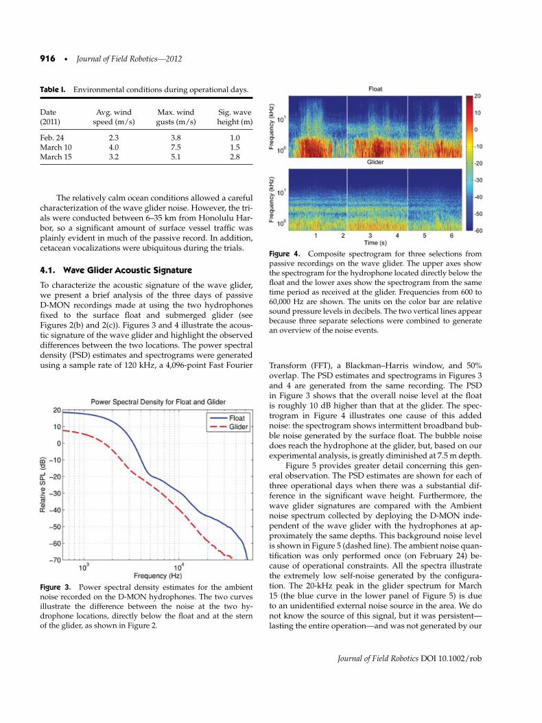
Figure 3. Power spectral density estimates for the ambientnoise recorded on the D-MON hydrophones. The two curvesillustrate the difference between the noise at the two hy-drophone locations, directly below the float and at the sternof the glider, as shown in Figure 2.
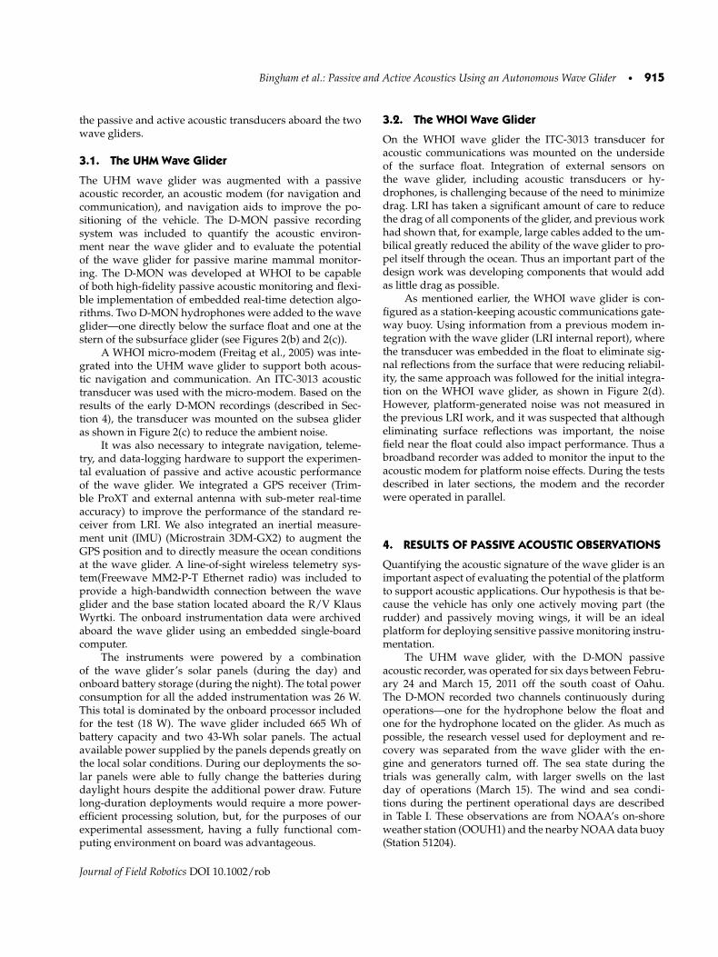
Figure 4. Composite spectrogram for three selections frompassive recordings on the wave glider. The upper axes showthe spectrogram for the hydrophone located directly below thefloat and the lower axes show the spectrogram from the sametime period as received at the glider. Frequencies from 600 to60,000 Hz are shown. The units on the color bar are relativesound pressure levels in decibels. The two vertical lines appearbecause three separate selections were combined to generatean overview of the noise events.
Transform (FFT), a Blackman–Harris window, and 50%overlap. The PSD estimates and spectrograms in Figures 3and 4 are generated from the same recording. The PSDin Figure 3 shows that the overall noise level at the floatis roughly 10 dB higher than that at the glider. The spec-trogram in Figure 4 illustrates one cause of this addednoise: the spectrogram shows intermittent broadband bub-ble noise generated by the surface float. The bubble noisedoes reach the hydrophone at the glider, but, based on ourexperimental analysis, is greatly diminished at 7.5 m depth.
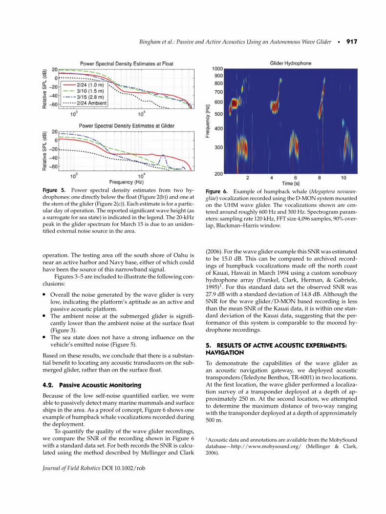
Figure 5 provides greater detail concerning this gen-eral observation. The PSD estimates are shown for each ofthree operational days when there was a substantial dif-ference in the significant wave height. Furthermore, thewave glider signatures are compared with the Ambientnoise spectrum collected by deploying the D-MON inde-pendent of the wave glider with the hydrophones at ap-proximately the same depths. This background noise levelis shown in Figure 5 (dashed line). The ambient noise quan-tification was only performed once (on February 24) be-cause of operational constraints. All the spectra illustratethe extremely low self-noise generated by the configura-tion. The 20-kHz peak in the glider spectrum for March15 (the blue curve in the lower panel of Figure 5) is dueto an unidentified external noise source in the area. We donot know the source of this signal, but it was persistent—lasting the entire operation—and was not generated by our
Journal of Field Robotics DOI 10.1002/rob
Bingham et al.: Passive and Active Acoustics Using an Autonomous Wave Glider • 917
Figure 5. Power spectral density estimates from two hy-drophones: one directly below the float (Figure 2(b)) and one atthe stern of the glider (Figure 2(c)). Each estimate is for a partic-ular day of operation. The reported significant wave height (asa surrogate for sea state) is indicated in the legend. The 20-kHzpeak in the glider spectrum for March 15 is due to an uniden-tified external noise source in the area.
operation. The testing area off the south shore of Oahu isnear an active harbor and Navy base, either of which couldhave been the source of this narrowband signal.
Figures 3–5 are included to illustrate the following con-clusions:
• Overall the noise generated by the wave glider is verylow, indicating the platform’s aptitude as an active andpassive acoustic platform.
• The ambient noise at the submerged glider is signifi-cantly lower than the ambient noise at the surface float(Figure 3).
• The sea state does not have a strong influence on thevehicle’s emitted noise (Figure 5).
Based on these results, we conclude that there is a substan-tial benefit to locating any acoustic transducers on the sub-merged glider, rather than on the surface float.
4.2. Passive Acoustic Monitoring
Because of the low self-noise quantified earlier, we wereable to passively detect many marine mammals and surfaceships in the area. As a proof of concept, Figure 6 shows oneexample of humpback whale vocalizations recorded duringthe deployment.
To quantify the quality of the wave glider recordings,we compare the SNR of the recording shown in Figure 6with a standard data set. For both records the SNR is calcu-lated using the method described by Mellinger and Clark
Figure 6. Example of humpback whale (Megaptera novaean-gliae) vocalization recorded using the D-MON system mountedon the UHM wave glider. The vocalizations shown are cen-tered around roughly 600 Hz and 300 Hz. Spectrogram param-eters: sampling rate 120 kHz, FFT size 4,096 samples, 90% over-lap, Blackman–Harris window.
(2006). For the wave glider example this SNR was estimatedto be 15.0 dB. This can be compared to archived record-ings of humpback vocalizations made off the north coastof Kauai, Hawaii in March 1994 using a custom sonobuoyhydrophone array (Frankel, Clark, Herman, & Gabriele,1995)1. For this standard data set the observed SNR was27.9 dB with a standard deviation of 14.8 dB. Although theSNR for the wave glider/D-MON based recording is lessthan the mean SNR of the Kauai data, it is within one stan-dard deviation of the Kauai data, suggesting that the per-formance of this system is comparable to the moored hy-drophone recordings.
5. RESULTS OF ACTIVE ACOUSTIC EXPERIMENTS:NAVIGATION
To demonstrate the capabilities of the wave glider asan acoustic navigation gateway, we deployed acoustictransponders (Teledyne Benthos, TR-6001) in two locations.At the first location, the wave glider performed a localiza-tion survey of a transponder deployed at a depth of ap-proximately 250 m. At the second location, we attemptedto determine the maximum distance of two-way rangingwith the transponder deployed at a depth of approximately500 m.
1Acoustic data and annotations are available from the MobySounddatabase—http://www.mobysound.org/ (Mellinger & Clark,2006).
Journal of Field Robotics DOI 10.1002/rob
918 • Journal of Field Robotics—2012
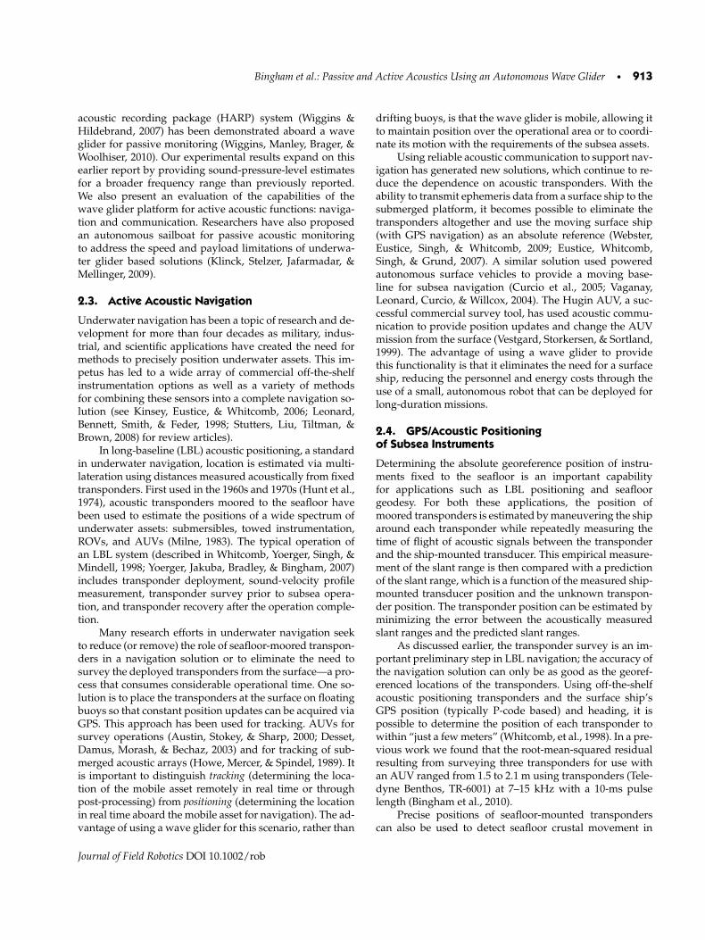
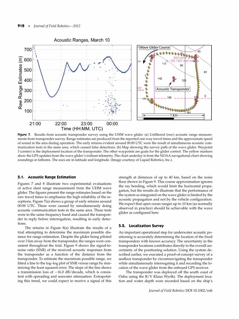
Figure 7. Results from acoustic transponder survey using the UHM wave glider. (a) Unfiltered (raw) acoustic range measure-ments from transponder survey. Range estimates are produced from the reported one-way travel times and the approximate speedof sound in the area during operation. The early returns evident around 00:00 UTC were the result of simultaneous acoustic com-munication tests in the same area, which caused false detections. (b) Map showing the survey path of the wave glider. Waypoint3 (center) is the deployment location of the transponder. The other waypoints are goals for the glider control. The yellow markersshow the GPS updates from the wave glider’s iridium telemetry. The chart underlay is from the NOAA navigational chart showingsoundings in fathoms. The axes are in latitude and longitude. (Image courtesy of Liquid Robotics, Inc.).
5.1. Acoustic Range Estimation
Figures 7 and 8 illustrate two experimental evaluationsof active slant range measurement from the UHM waveglider. The figures present the range estimates based on theraw travel times to emphasize the high reliability of the re-ceptions. Figure 7(a) shows a group of early returns around00:00 UTC. These were caused by simultaneously doingacoustic communication tests in the same area. These testswere in the same frequency band and caused the transpon-der to reply before interrogation, resulting in early detec-tions.
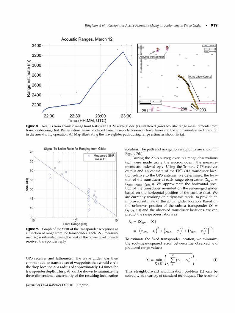
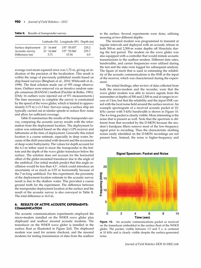
The returns in Figure 8(a) illustrate the results of atrial attempting to determine the maximum possible dis-tance for range estimation. Despite the glider being pilotedover 3 km away from the transponder, the ranges were con-sistent throughout the trial. Figure 9 shows the signal-to-noise ratio (SNR) of the received acoustic responses fromthe transponder as a function of the distance from thetransponder. To estimate the maximum possible range, wefitted a line to the log–log plot of SNR versus range by min-imizing the least squared error. The slope of the line showsa transmission loss of −16.0 dB/decade, which is consis-tent with spreading and seawater attenuation. Extrapolat-ing this trend, we could expect to receive a signal of this
strength at distances of up to 40 km, based on the noisefloor shown in Figure 9. This coarse approximation ignoresthe ray bending, which would limit the horizontal propa-gation, but the results do illustrate that the performance ofthe system as integrated on the wave glider is limited by theacoustic propagation and not by the vehicle configuration.We expect that open ocean ranges up to 10 km (as normallyobserved in practice) should be achievable with the waveglider as configured here.
5.2. Localization Survey
An important operational step for underwater acoustic po-sitioning is accurately determining the location of the fixedtransponders with known accuracy. The uncertainty in thetransponder locations contributes directly to the overall un-certainty of the positioning solution. Using the system de-scribed earlier, we executed a proof-of-concept survey of aseafloor transponder by circumnavigating the transponderwhile simultaneously interrogating it and recording the lo-cation of the wave glider from the onboard GPS receiver.
The transponder was deployed off the south coast ofOahu using the R/V Klaus Wyrtki. The deployment loca-tion and water depth were recorded based on the ship’s
Journal of Field Robotics DOI 10.1002/rob
Bingham et al.: Passive and Active Acoustics Using an Autonomous Wave Glider • 919
Figure 8. Results from acoustic range limit tests with UHM wave glider. (a) Unfiltered (raw) acoustic range measurements fromtransponder range test. Range estimates are produced from the reported one-way travel times and the approximate speed of soundin the area during operation. (b) Map illustrating the wave glider path during range estimates shown in (a).
Figure 9. Graph of the SNR of the transponder receptions asa function of range from the transponder. Each SNR measure-ment (o) is estimated using the peak of the power level for eachreceived transponder reply.
GPS receiver and fathometer. The wave glider was thencommanded to transit a set of waypoints that would circlethe drop location at a radius of approximately 1.4 times thetransponder depth. This path can be shown to minimize thethree-dimensional uncertainty of the resulting localization
solution. The path and navigation waypoints are shown inFigure 7(b).
During the 2.5-h survey, over 971 range observations(zri
) were made using the micro-modem; the measure-ments are indexed by i. Using the Trimble GPS receiveroutput and an estimate of the ITC-3013 transducer loca-tion relative to the GPS antenna, we determined the loca-tion of the transducer at each range observation (Xgpsi
=(xgpsi
, ygpsi, zgpsi
)). We approximate the horizontal posi-tion of the transducer mounted on the submerged gliderbased on the horizontal position of the surface float. Weare currently working on a dynamic model to provide animproved estimate of the actual glider location. Based onthe unknown position of the subsea transponder (Xt =(xt , yt , zt )) and the observed transducer locations, we canpredict the range observations as
zri= ‖Xgpsi
− Xt‖
=[(
xgpsi− xt
)2 +(ygpsi
− yt
)2 +(zgpsi
− zt
)2]1/2.
To estimate the fixed transponder location, we minimizethe root-mean-squared error between the observed andpredicted range values:
Xt = minXt∈R
3
⎛⎝
√√√√ N∑i
(zri
− zri
)2
⎞⎠ . (1)
This straightforward minimization problem (1) can besolved with a variety of standard techniques. The resulting
Journal of Field Robotics DOI 10.1002/rob
920 • Journal of Field Robotics—2012
Table II. Results of transponder survey.
Latitude (N) Longitude (W) Depth (m)
Surface deployment 21◦ 16.664′ 157◦ 55.057′ 235.2Acoustic survey 21◦ 16.666′ 157◦ 55.066′ 235.7Difference (m) 3.71 15.54 0.5
average root-mean-squared error was 1.72 m, giving an in-dication of the precision of the localization. This result iswithin the range of previously published results based onship-based surveys (Bingham et al., 2010; Whitcomb et al.,1998). The final solution made use of 955 range observa-tions. Outliers were removed via an iterative random sam-ple consensus (RANSAC) method (Fischler & Bolles, 1981).(Only 16 outliers were rejected out of 971 measurements.)The time necessary to complete the survey is constrainedby the speed of the wave glider, which is limited to approx-imately 0.75 m/s (1.5 kts). Surveys using a surface ship aretypically carried out at similar speeds to reduce flow noiseand allow for sufficient coverage.
Table II summarizes the results of the transponder sur-vey, comparing the acoustic survey results with the infor-mation from the deployment location. The deployment lo-cation was estimated based on the ship’s GPS receiver andfathometer at the time of deployment. Generally this initiallocation is a coarse estimate, especially in deep water, be-cause of the drift associated with descent and the accuraciesof deep-water bathymetry. The values for depth account forthe 6.1-m tether used to moor the transponder to the bot-tom and the depth of the wave glider transducer below thesurface. The solution does not account for the horizontaloffset of the glider-mounted transducer due to the angle ofthe umbilical. Our initial models predict that this angle os-cillation would be less than 4.5◦, which could introduce anuncertainty of as much as 0.55 m horizontally because ofthe 7-m-long umbilical. For this experiment, the proximityof the deployment location estimate to the acoustic surveyresult is due to the shallow water. This provided a coarseground truth for the experiment. The difference betweenthe transponder deployment location at the surface and theresult of the acoustic survey is also conveyed in Table II.The total difference is 16.0 m.
6. RESULTS OF ACTIVE ACOUSTIC EXPERIMENTS:COMMUNICATION
The acoustic communications experiments employed themicro-modem installed on the WHOI wave glider plusshipboard and seafloor moored acoustic modems. Thetransducer on the WHOI wave glider is installed in thesurface float as illustrated in Figure 2(d). The shipboardmodem was used for system checkout, and the mooredmodems for testing transmission of data from the seafloor
to the surface. Several experiments were done, utilizingmooring at two different depths.
The moored modem was programmed to transmit atregular intervals and deployed with an acoustic release inboth 500-m and 2,500-m water depths off Honolulu dur-ing the test period. The modem on the wave glider wasalso equipped with a controller that would initiate acoustictransmissions to the seafloor modem. Different data rates,bandwidths, and carrier frequencies were utilized duringthe test and the data were logged for subsequent analysis.The figure of merit that is used in estimating the reliabil-ity of the acoustic communications is the SNR at the inputof the receiver, which was characterized during the experi-ment.
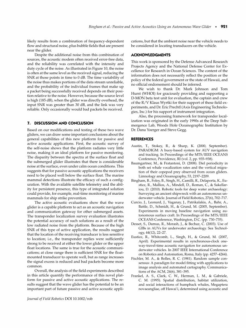
The initial findings, after review of data collected fromboth the micro-modem and the recorder, were that thewave glider modem was able to receive signals from thetransmitter at depths of 500 and 2,500 m and at ranges in ex-cess of 3 km, but that the reliability and the input SNR var-ied with the local noise field around the surface receiver. Anexample spectrogram of a received acoustic packet at 10-kHz carrier with 5-kHz bandwidth is shown in Figure 10.The 4-s-long packet is clearly visible. More interesting is thenoise that is present as well. Note that the spectrum is dif-ferent from that recorded by the D-MON because the mo-dem’s bandpass filters remove most of the low-frequencysignal prior to recording. Thus the characteristic sloshingnoises easily identified on the D-MON recordings are notpresent here. Instead, the noise is higher-frequency and
Figure 10. An acoustic communications packet as receivedon the transducer embedded in the surface float of the WHOIglider. The packet, visible between 1.5 and 5 s, is centeredat 10 kHz and is clearly visible despite the surface-generatednoise.
Journal of Field Robotics DOI 10.1002/rob
Bingham et al.: Passive and Active Acoustics Using an Autonomous Wave Glider • 921
likely results from a combination of frequency-dependentflow and structural noise, plus bubble fields that are presentnear the glider.
Despite the additional noise from this combination ofsources, the acoustic modem often received error-free data,and the reliability was correlated with the intensity andduty cycle of the noise. As illustrated in Figure 10, the noiseis often at the same level as the received signal, reducing theSNR at those points in time to 0 dB. The time variability ofthe noise thus makes portions of the data stream unreliable,and the probability of the individual frames that make upa packet being successfully received depends on their posi-tion relative to the noise. However, because the source levelis high (185 dB), when the glider was directly overhead, theinput SNR was greater than 30 dB, and the link was veryreliable. Only occasionally would bad packets be received.
7. DISCUSSION AND CONCLUSION
Based on our modifications and testing of these two wavegliders, we can draw some important conclusions about thegeneral capabilities of this new platform for passive andactive acoustic applications. First, the acoustic survey ofthe self-noise shows that the platform radiates very littlenoise, making it an ideal platform for passive monitoring.The disparity between the spectra at the surface float andthe submerged glider illustrates that there is considerablenoise at the surface, even under calm ocean conditions. Thissuggests that for passive acoustic applications the receiversneed to be placed well below the surface float. The marinemammal detections illustrate the efficacy of such a config-uration. With the available satellite telemetry and the abil-ity for persistent presence, this type of integrated solutioncould provide, for example, real-time monitoring of marinemammals for ship strike prevention.
The active acoustic evaluations show that the waveglider is a capable platform to act as an acoustic navigationand communication gateway for other submerged assets.The transponder localization survey evaluation illustratesthe potential accuracy of such solutions as a result of thelow radiated noise from the platform. Because of the highSNR of this type of active application, the results suggestthat the location of the receiving transducer is less sensitiveto location; i.e., the transponder replies were sufficientlystrong to be received at either the lower glider or the upperfloat locations. The same is true for the acoustic communi-cations; at close range there is sufficient SNR for the float-mounted transducer to operate well, but as range increasesthe signal excess is reduced and bad packets become morecommon.
Overall, the analysis of the field experiments describedin this article quantify the performance of this novel plat-form for passive and active acoustic applications. The re-sults suggest that the wave glider has the potential to be animportant part of future passive and active acoustic appli-
cations, but that the ambient noise near the vehicle needs tobe considered in locating transducers on the vehicle.
ACKNOWLEDGMENTS
This work is sponsored by the Defense Advanced ResearchProjects Agency and the National Defense Center for Ex-cellence for Research in Ocean Sciences. The content of theinformation does not necessarily reflect the position or thepolicy of the federal government or the state of Hawaii, andno official endorsement should be inferred.
We wish to thank Dr. Mark Johnson and TomHurst (WHOI) for graciously providing and supporting aD-MON beta test unit for evaluation, the captain and crewof the R/V Klaus Wyrtki for their support of these field ex-periments, and Dr. Eric Prechtl (Axis Engineering Technolo-gies, Inc.) for his support of instrument integration.
Also, the processing framework for transponder local-ization was originated in the early 1990s at the Deep Sub-mergence Lab, Woods Hole Oceanographic Institution byDr. Dana Yoerger and Steve Gegg.
REFERENCES
Austin, T., Stokey, R., & Sharp, K. (2000, September).PARADIGM: A buoy-based system for AUV navigationand tracking. In Proceedings of the MTS/IEEE OCEANSConference, Providence, RI (vol. 2, pp. 935–938).
Baumgartner, M., & Fratantoni, D. (2008). Diel periodicity inboth sei whale vocalization rates and the vertical migra-tion of their copepod prey observed from ocean gliders.Limnology and Oceanography, 53, 2197–2209.
Bingham, B., Foley, B., Singh, H., Camilli, R., Delaporta, K., Eu-stice, R., Mallios, A., Mindell, D., Roman, C., & Sakellar-iou, D. (2010). Robotic tools for deep water archaeology:Surveying an ancient shipwreck with an autonomous un-derwater vehicle. Journal of Field Robotics, 27(6), 702–717.
Curcio, J., Leonard, J., Vaganay, J., Patrikalakis, A., Bahr, A.,Battle, D., Schmidt, H., & Grund, M. (2005, September).Experiments in moving baseline navigation using au-tonomous surface craft. In Proceedings of the MTS/IEEEOCEANS Conference, Washington, D.C. (pp. 730–735).
Desset, S., Damus, R., Morash, J., & Bechaz, C. (2003). Use ofGIBs in AUVs for underwater archaeology. Sea Technol-ogy, 44(12), 22–27.
Eustice, R., Whitcomb, L., Singh, H., & Grund, M. (2007,April). Experimental results in synchronous-clock one-way-travel-time acoustic navigation for autonomous un-derwater vehicles. In 2007 IEEE International Conferenceon Robotics and Automation, Roma, Italy (pp. 4257–4264).
Fischler, M. A., & Bolles, R. C. (1981). Random sample con-sensus: A paradigm for model fitting with applications toimage analysis and automated cartography. Communica-tions of the ACM, 24(6), 381–395.
Frankel, A. S., Clark, C. W., Herman, L. M., & Gabriele,C. M. (1995). Spatial distribution, habitat utilization,and social interactions of humpback whales, Megapteranovaeangliae, off Hawai’i, determined using acoustic and
Journal of Field Robotics DOI 10.1002/rob
922 • Journal of Field Robotics—2012
visual techniques. Canadian Journal of Zoology, 73(6),1134–1146.
Freitag, L., Grund, M., Singh, S., Partan, J., Koski, P., & Ball,K. (2005). The WHOI micro-modem: An acoustic commu-nications and navigation system for multiple platforms.In Proceedings of the MTS/IEEE OCEANS Conference(vol. 2, pp. 1086–1092).
Frye, D., Ware, J., Grund, M., Partan, J., Koski, P., Singh, S., Fre-itag, L., Collins, J., & Detrick, R. (2005). An acoustically-linked deep-ocean observatory. In Proceedings of the IEEEOCEANS 2005–Europe Conference, Brest, France (vol. 2,pp. 969–974).
Fujita, M., Ishikawa, T., Mochizuki, M., Sato, M., Toyama,S., Katayama, M., Kawai, K., Matsumoto, Y., Yabuki, T.,Asada, A., & Colombo, O. L. (2006). GPS/acoustic seafloorgeodetic observation: Method of data analysis and its ap-plication. Earth Planets Space, 58, 265–275.
Hine, R., Willcox, S., Hine, G., & Richardson, T. (2009). Thewave glider: A wave-powered autonomous marine ve-hicle. In Proceedings of MTS/IEEE OCEANS Conference(pp. 1–6).
Howe, B. M., & Boyd, M. L. (2008). Using seagliders for acous-tic receiving and communication. Journal Acoustical Soci-ety of America (Abstract), 123, 3913.
Howe, B. M., Mercer, J. A., & Spindel, R. C. (1989). A floatingacoustic-satellite (FAST) range. In Proceedings of the Con-ference on Marine Data Systems, New Orleans, Washing-ton, D.C. (pp. 225–230). Marine Technology Society.
Hunt, M., Marquet, W., Moller, D., Peal, K., Smith, W.,& Spindel, R. (1974). An acoustic navigation system.(Tech. Rep. WHOI-74-6). Woods Hole OceanographicInstitution, Wood Hole, MA.
Kinsey, J. C., Eustice, R. M., & Whitcomb, L. L. (2006). Under-water vehicle navigation: Recent advances and new chal-lenges. Invited paper presented at the IFAC Conference onManoeuvring and Control of Marine Craft, Lisbon, Portu-gal.
Klinck, H., Stelzer, R., Jafarmadar, K., & Mellinger, D. (2009,July). AAS Endurance: An autonomous acoustic sailboatfor marine mammal research. In Proceedings of Interna-tional Robotic Sailing Conference, Matosinhos, Portugal(pp. 43–48).
Kussat, N. H., & Chadwell, C. D. (2005). Absolute position-ing of an autonomous underwater vehicle using GPS andacoustic measurements. IEEE Journal of Oceanic Engi-neering, 30(1), 153–164.
Lawson, R., Graham, D., Stalin, S., Meinig, C., Tagawa,D., Lawrence-Slavas, N., Hibbins, R., & Ingham, B.(2011, September). The next generation easy-to-deploy(ETD) tsunami assessment buoy. In Proceedings of theMTS/IEEE OCEANS Conference, Kona, HI (pp. 1–8).
Leonard, J. J., Bennett, A. A., Smith, C. M., & Feder, H. J. S.(1998). Autonomous underwater vehicle navigation (Tech.Rep. 98-1), Marine Robotics Laboratory, Cambridge, MA.
Meinig, C., Stalin, S. E., Nakamura, A. I., & Milburn, H. B.(2005). Real-time deep-ocean tsunami measuring, mon-itoring, and reporting system: The NOAA DART IIdescription and disclosure (Tech. Rep.). National Oceanic
and Atmospheric Administration, Pacific Marine Envi-ronmental Laboratory, Seattle, WA.
Mellinger, D., & Clark, C. (2006). MobySound: A referencearchive for studying automatic recognition of marinemammal sounds. Applied Acoustics, 67(11–12), 1226–1242.
Mellinger, D. K., & Barlow, J. (2003). Future directions formarine mammal acoustic surveys: Stock assessment andhabitat use (Tech Contrib. 2557). NOAA Pacific MarineEnvirnomental Laboratory, Seattle, WA.
Mellinger, D. K., Stafford, K. M., Moore, S. E., Dziak, R. P.,& Matsumoto, H. (2007). An overview of fixed passiveacoustic observation methods for cetaceans. Oceanogra-phy, 20(4), 36–45.
Milne, P. H. (1983). Underwater acoustic positioning systems.Houston: Gulf Publishing Company.
Moore, S. E., Howe, B. M., Stafford, K. M., & Boyd, M. L. (2008).Including whale call detection in standard ocean measure-ments: Applications of acoustic seagliders. Marine Tech-nology Society (MTS) Journal, 41, 53–57.
Obana, K., Katao, H., & Ando, M. (2000). Seafloor positioningsystem with GPS–acoustic link for crustal dynamics obser-vation: A preliminary result from experiments in the sea.Earth Planets Space, 52, 415–423.
Osada, Y., Fujimoto, H., Miura, S., Sweeney, A., Kanazawa, T.,Nakao, S., Sakai, S., Hildebrand, J., & Chadwell, C. (2003).Estimation and correction for the effect of sound velocityvariation on GPS/acoustic seafloor positioning: An exper-iment off Hawaii Island. Earth Planets Space, 55, e17–e20.
Spiess, F. N., Boegeman, D. E., Zimmerman, R., Chadwell,C. D., & Hildebrand, J. A. (1997). Precision transpon-der (Tech. Rep. SIO Ref. 97-3). University of California,San Diego, Scripps Institition of Oceanography, La Jolla,CA.
Spiess, F. N., Chadwell, C. D., Hildebrand, J. A., Young,L. E., Purcell, G. H. Jr., and Dragert, H. (1998). Pre-cise GPS/acoustic positioning of seafloor reference pointsfor tectonic studies. Physics of Earth Planetery Interiors,108(1), 102–112.
Stutters, L., Liu, H., Tiltman, C., & Brown, D. (2008). Navi-gation technologies for autonomous underwater vehicles.IEEE Transactions on Systems, Man, and Cybernetics, PartC: Applications and Reviews, 38(4), 581–589.
Sweeney, A. D., Chadwell, C. D., Hildebrand, J. A., & Spiess,F. N. (2005). Centimeter-level positioning of seaflooracoustic transponders from a deeply-towed interrogator.Marine Geodesy, 28(1), 39–70.
Vaganay, J., Leonard, J., Curcio, J., & Willcox, J. (2004). Experi-mental validation of the moving long base-line navigationconcept. In Proceedings of the IEEE/OES Conference onAutonomous Underwater Vehicles (pp. 59–65).
Vestgard, K., Storkersen, N., & Sortland, J. (1999). Seabed sur-veying with Hugin AUV. In Proceedings of the 11th In-ternational Symposium on Unmanned Untethered Sub-mersible Technology.
Webster, S., Eustice, R., Singh, H., & Whitcomb, L. (2009, Oc-tober). Preliminary deep water results in single-beaconone-way-travel-time acoustic navigation for underwater
Journal of Field Robotics DOI 10.1002/rob
Bingham et al.: Passive and Active Acoustics Using an Autonomous Wave Glider • 923
vehicles. In IEEE/RSJ International Conference on Intelli-gent Robots and Systems, 2009. (IROS 2009), St. Louis, MO(pp. 2053–2060).
Whitcomb, L., Yoerger, D., Singh, H., & Mindell, D. (1998).Towards precision robotic maneuvering, survey, and ma-nipulation in unstructured undersea environments. In Y.Shirai, & S. Hirose (Eds.), Robotics research—The EighthInternational Symposium (pp. 45–54). London: Springer-Verlag.
Wiggins, S., Manley, J., Brager, E., & Woolhiser, B. (2010,September). Monitoring marine mammal acoustics usingwave glider. In Proceedings of the MTS/IEEE OCEANSConference, Seattle, WA (pp. 1–4).
Wiggins, S. M., & Hildebrand, J. A. (2007, April). High-frequency acoustic recording package (HARP) forbroad-band, long-term marine mammal monitoring. InSymposium on Underwater Technology and Workshop
on Scientific Use of Submarine Cables and RelatedTechnologies, Tokyo, Japan (pp. 551–557).
Willcox, S., Meinig, C., Sabine, C., Lawrence-Slavas, N.,Richardson, T., Hine, R., & Manley, J. (2009). An au-tonomous mobile platform for underway surface carbonmeasurements in open-ocean and coastal waters. InProceedings of the MTS/IEEE OCEANS Conference(pp. 1–8).
Yamada, T., Ando, M., Tadokoro, K., Sato, K., Okuda, T.,& Oike, K. (2002). Error evaluation in acoustic posi-tioning of a single transponder for seafloor crustaldeformation measurements. Earth Planets Space, 54, 871–881.
Yoerger, D. R., Jakuba, M., Bradley, A. M., & Bingham, B.(2007). Techniques for deep sea near bottom survey usingan autonomous underwater vehicle. International Journalof Robotics Research, 26(1), 41–54.
Journal of Field Robotics DOI 10.1002/rob