PASSENGER AND DRY CARGO SHIPS - DNV GL · PDF filePASSENGER AND DRY CARGO SHIPS JANUARY 2011...
137
RULES FOR CLASSIFICATION OF DET NORSKE VERITAS Veritasveien 1, NO-1322 Høvik, Norway Tel.: +47 67 57 99 00 Fax: +47 67 57 99 11 SHIPS NEWBUILDINGS SPECIAL SERVICE AND TYPE ADDITIONAL CLASS PART 5 CHAPTER 2 PASSENGER AND DRY CARGO SHIPS JANUARY 2011 CONTENTS PAGE Sec. 1 General Requirements .......................................................................................................... 9 Sec. 2 Passenger Ships ................................................................................................................. 11 Sec. 3 Ferries ............................................................................................................................... 23 Sec. 4 General Cargo Carriers ..................................................................................................... 37 Sec. 5 Dry Bulk Cargo Carriers .................................................................................................... 51 Sec. 6 Container Carriers ............................................................................................................. 71 Sec. 7 Car Carriers ........................................................................................................................ 92 Sec. 8 Enhanced Strength for Bulk Carriers ................................................................................. 97 Sec. 9 Ships Specialised for the Carriage of a Single Type of Dry Bulk Cargo ........................ 128 Sec. 10 Carriage of Refrigerated Containers ................................................................................ 129 Sec. 11 Great Lakes Bulk Carriers ............................................................................................... 134
Transcript of PASSENGER AND DRY CARGO SHIPS - DNV GL · PDF filePASSENGER AND DRY CARGO SHIPS JANUARY 2011...
RULES FORCLASSIFICATION OF
SHIPS
NEWBUILDINGS
SPECIAL SERVICE AND TYPEADDITIONAL CLASS
PART 5 CHAPTER 2
PASSENGER AND DRY CARGO SHIPSJANUARY 2011
CONTENTS PAGE
Sec. 1 General Requirements.......................................................................................................... 9Sec. 2 Passenger Ships ................................................................................................................. 11Sec. 3 Ferries ............................................................................................................................... 23Sec. 4 General Cargo Carriers ..................................................................................................... 37Sec. 5 Dry Bulk Cargo Carriers.................................................................................................... 51Sec. 6 Container Carriers ............................................................................................................. 71Sec. 7 Car Carriers........................................................................................................................ 92Sec. 8 Enhanced Strength for Bulk Carriers................................................................................. 97Sec. 9 Ships Specialised for the Carriage of a Single Type of Dry Bulk Cargo ........................ 128Sec. 10 Carriage of Refrigerated Containers ................................................................................ 129Sec. 11 Great Lakes Bulk Carriers ............................................................................................... 134
DET NORSKE VERITASVeritasveien 1, NO-1322 Høvik, Norway Tel.: +47 67 57 99 00 Fax: +47 67 57 99 11
CHANGES IN THE RULES
GeneralThe present edition of the rules includes additions and amendments approved by the Executive Committee as of November2010 and supersedes the July 2010 edition of the same chapter.The rule changes come into force as indicated below.This chapter is valid until superseded by a revised chapter.
Main changes coming into force 1 January 2011• Sec.2 Passenger Ships — D600: Supplementary lighting is updated to cover new SOLAS requirements.
• Sec.3 Ferries— A500: Internal communication is now covered by DNV Statutory Interpretations.
• Sec.5 Dry Bulk Cargo Carriers— A202 and A203: rule reference update.
Corrections and ClarificationsIn addition to the above stated rule requirements, a number of corrections and clarifications have been made in the existingrule text.
The electronic pdf version of this document found through http://www.dnv.com is the officially binding version© Det Norske Veritas
Any comments may be sent by e-mail to [email protected] subscription orders or information about subscription terms, please use [email protected] Typesetting (Adobe Frame Maker) by Det Norske Veritas
If any person suffers loss or damage which is proved to have been caused by any negligent act or omission of Det Norske Veritas, then Det Norske Veritas shall pay compensation tosuch person for his proved direct loss or damage. However, the compensation shall not exceed an amount equal to ten times the fee charged for the service in question, provided thatthe maximum compensation shall never exceed USD 2 million.In this provision "Det Norske Veritas" shall mean the Foundation Det Norske Veritas as well as all its subsidiaries, directors, officers, employees, agents and any other acting on behalfof Det Norske Veritas.
Rules for Ships, January 2011 Pt.5 Ch.2 Contents – Page 3
CONTENTS
Sec. 1 General Requirements ....................................................................................................................... 9
A. Classification................................................................................................................................................................... 9A 100 Application............................................................................................................................................................ 9A 200 Class notations ...................................................................................................................................................... 9
B. Definitions..................................................................................................................................................................... 10B 100 Symbols .............................................................................................................................................................. 10
C. Documentation .............................................................................................................................................................. 10C 100 General................................................................................................................................................................ 10
Sec. 2 Passenger Ships ............................................................................................................................... 11
A. General .......................................................................................................................................................................... 11A 100 Classification ...................................................................................................................................................... 11A 200 Definitions .......................................................................................................................................................... 11A 300 Documentation requirements .............................................................................................................................. 11
B. Hull Arrangement and Strength .................................................................................................................................... 11B 100 General................................................................................................................................................................ 11B 200 Global strength.................................................................................................................................................... 11B 300 Deck structure ..................................................................................................................................................... 12B 400 Pillars .................................................................................................................................................................. 13B 500 Cofferdam structure ............................................................................................................................................ 13B 600 Movable glass roofs ............................................................................................................................................ 13B 700 Windows and glass structure .............................................................................................................................. 14B 800 Fatigue ................................................................................................................................................................ 14
C. Machinery and Systems ................................................................................................................................................ 14C 100 General................................................................................................................................................................ 14
D. Emergency Source of Electrical Power and Emergency Installations .......................................................................... 15D 100 General................................................................................................................................................................ 15D 200 Services to be supplied ....................................................................................................................................... 15D 300 Arrangement of emergency source(s) of power.................................................................................................. 16D 400 Transitional source of emergency power............................................................................................................ 17D 500 Low-location lighting ......................................................................................................................................... 17D 600 Supplementary lighting ...................................................................................................................................... 17D 700 Location of emergency switchboard, distribution .............................................................................................. 17D 800 Inclinations (list and trim of ship)....................................................................................................................... 18D 900 Periodical testing................................................................................................................................................. 18D 1000 Starting arrangements for emergency generating sets ........................................................................................ 18
E. Fire Safety Measures for Passenger Ships ................................................................................................................... 18E 100 Application.......................................................................................................................................................... 18E 200 Rule references and definitions........................................................................................................................... 18E 300 Documentation.................................................................................................................................................... 18E 400 Main vertical zones and horizontal zones (SOLAS Reg. II-2/9.2.2.1) ............................................................... 18E 500 Protection of stairways and lifts in accommodation area (SOLAS Reg. II-2/9.2.2.5) ....................................... 19E 600 Means of escape from accommodation spaces, service spaces and control stations
(SOLAS Reg. II-2/13.3.2.1 - 13.3.2.4) ............................................................................................................... 19E 700 Means of escape from machinery spaces (SOLAS Reg. II-2/13.4.1)................................................................. 20E 800 Means of escape from special category and open ro-ro spaces to which any passengers
carried can have access (SOLAS Reg. II-2/13.5) ............................................................................................... 20E 900 Additional requirements to means of escape for ro-ro passenger ships.............................................................. 20
F. Stability and Watertight Integrity ................................................................................................................................. 21F 100 Application.......................................................................................................................................................... 21F 200 Documentation.................................................................................................................................................... 21F 300 Intact stability ..................................................................................................................................................... 22F 400 Subdivision and damage stability ....................................................................................................................... 22
Sec. 3 Ferries ............................................................................................................................................... 23
A. General .......................................................................................................................................................................... 23A 100 Classification ...................................................................................................................................................... 23A 200 Assumptions........................................................................................................................................................ 23A 300 Documentation.................................................................................................................................................... 23A 400 Definitions .......................................................................................................................................................... 24A 500 Internal communication ...................................................................................................................................... 25
DET NORSKE VERITAS
Rules for Ships, January 2011 Pt.5 Ch.2 Contents – Page 4
A 600 Certification of bow doors monitoring system ................................................................................................... 25
B. Hull Arrangement and Strength .................................................................................................................................... 25B 100 Vehicle decks, ramps and lifts ............................................................................................................................ 25B 200 Securing of vehicles............................................................................................................................................ 25B 300 Transverse strength ............................................................................................................................................. 25
C. Openings and Closing Appliances ................................................................................................................................ 26C 100 Doors................................................................................................................................................................... 26C 200 Access openings.................................................................................................................................................. 26C 300 Watertight integrity from the ro-ro deck (bulkhead deck) to spaces below ....................................................... 26
D. Bow Doors .................................................................................................................................................................... 26D 100 Application and definitions................................................................................................................................. 26D 200 Arrangement ....................................................................................................................................................... 27D 300 Materials ............................................................................................................................................................. 27D 400 Design Loads ...................................................................................................................................................... 27D 500 Strength criteria................................................................................................................................................... 29D 600 Structural arrangement........................................................................................................................................ 30D 700 Plating ................................................................................................................................................................. 30D 800 Stiffeners ............................................................................................................................................................. 30D 900 Girders ................................................................................................................................................................ 31D 1000 Closing arrangement, general ............................................................................................................................. 31D 1100 Closing arrangement, strength ............................................................................................................................ 32D 1200 Closing arrangement, system for operation and indication and monitoring....................................................... 33
E. Inlets and Drainage Arrangement ................................................................................................................................. 34E 100 Air intakes, ventilators, etc. ................................................................................................................................ 34E 200 Drainage of vehicle deck (class notation A) ....................................................................................................... 35E 300 Freeing ports (class notation B).......................................................................................................................... 35
F. Stability ......................................................................................................................................................................... 35F 100 General................................................................................................................................................................ 35
G. Life Saving Appliances and Arrangements .................................................................................................................. 35G 100 Application.......................................................................................................................................................... 35G 200 Additional requirements for ro-ro passenger ships (Regulation III/26).............................................................. 35
Sec. 4 General Cargo Carriers .................................................................................................................. 37
A. General .......................................................................................................................................................................... 37A 100 Classification ...................................................................................................................................................... 37A 200 Documentation.................................................................................................................................................... 37
B. Hull Arrangement and Strength .................................................................................................................................... 38B 100 General................................................................................................................................................................ 38B 200 Strength analysis levels....................................................................................................................................... 39B 300 Longitudinal strength .......................................................................................................................................... 39B 400 Transverse strength ............................................................................................................................................. 39B 500 Fatigue ................................................................................................................................................................ 39B 600 Hatch side cantilevers ......................................................................................................................................... 39B 700 External vehicle ramps........................................................................................................................................ 41B 800 Internal ramps and lifts ....................................................................................................................................... 41B 900 Ceilings and cargo battens .................................................................................................................................. 42B 1000 Protection of cargo.............................................................................................................................................. 42B 1100 Support of cargo handling equipment................................................................................................................. 42B 1200 Securing points for lashing ................................................................................................................................. 42B 1300 Steel coils ............................................................................................................................................................ 43
C. Permanent Decks for Wheel Loading ........................................................................................................................... 43C 100 General................................................................................................................................................................ 43C 200 Design loads........................................................................................................................................................ 43C 300 Plating ................................................................................................................................................................. 45C 400 Stiffeners ............................................................................................................................................................. 46C 500 Girders ................................................................................................................................................................ 47C 600 Details ................................................................................................................................................................. 48
D. Detection of Water Ingress in Single Hold Cargo Ships ............................................................................................. 49D 100 Performance requirements .................................................................................................................................. 49D 200 Installation .......................................................................................................................................................... 50D 300 Survey on board .................................................................................................................................................. 50
DET NORSKE VERITAS
Rules for Ships, January 2011 Pt.5 Ch.2 Contents – Page 5
Sec. 5 Dry Bulk Cargo Carriers................................................................................................................. 51
A. General .......................................................................................................................................................................... 51A 100 Classification ...................................................................................................................................................... 51A 200 Common Structural Rules................................................................................................................................... 58A 300 Documentation.................................................................................................................................................... 58A 400 Structural and leak testing................................................................................................................................... 59A 500 Grab cargo handling............................................................................................................................................ 59
B. Design Loads................................................................................................................................................................. 59B 100 Design cargo density and angle of repose........................................................................................................... 59B 200 Lateral pressure loads ......................................................................................................................................... 60
C. Bulk Carriers (full breadth holds) ................................................................................................................................. 61C 100 Hull arrangement ................................................................................................................................................ 61C 200 Longitudinal strength .......................................................................................................................................... 61C 300 Plating and stiffeners .......................................................................................................................................... 61C 400 Girder systems .................................................................................................................................................... 62C 500 Corrosion prevention .......................................................................................................................................... 64
D. Ore Carriers (holds between longitudinal bulkheads) .................................................................................................. 65D 100 Hull arrangement ................................................................................................................................................ 65D 200 Plating and stiffeners .......................................................................................................................................... 65D 300 Girder systems .................................................................................................................................................... 65
E. Detection of Water Ingress into Cargo Holds Ballast and Dry Spaces, and Availability of Drainage forward Spaces .......................................................................................................................................... 66
E 100 Performance requirements .................................................................................................................................. 66E 200 Installation .......................................................................................................................................................... 67E 300 Survey on board .................................................................................................................................................. 67E 400 Availability of drainage forward spaces ............................................................................................................ 67
F. Requirements for the Fitting of a Forecastle for Bulk Carriers, Ore Carriers and Combination Carriers .................... 67F 100 Application and definition .................................................................................................................................. 67F 200 Dimensions ......................................................................................................................................................... 68
G. Access ........................................................................................................................................................................... 68G 100 Access to and within spaces in, or forward of, the cargo area............................................................................ 68
H. Optional Class Notations EC and EL-2 ....................................................................................................................... 69H 100 General................................................................................................................................................................ 69H 200 Optional class notation EC ................................................................................................................................. 69H 300 Optional class notation EL-2 .............................................................................................................................. 69
Sec. 6 Container Carriers .......................................................................................................................... 71
A. General .......................................................................................................................................................................... 71A 100 Classification ...................................................................................................................................................... 71A 200 Scope................................................................................................................................................................... 71A 300 Assumptions........................................................................................................................................................ 71A 400 Definitions .......................................................................................................................................................... 72A 500 Documentation requirements .............................................................................................................................. 73A 600 Container stowage............................................................................................................................................... 73A 700 Certification of container securing fittings ......................................................................................................... 73
B. Longitudinal and Local Strength................................................................................................................................... 74B 100 Definitions .......................................................................................................................................................... 74B 200 Longitudinal and buckling strength .................................................................................................................... 74B 300 Plating and stiffeners .......................................................................................................................................... 77B 400 Strength evaluation of wave breaker and supporting structure........................................................................... 79
C. Cellular Container Hold Structures............................................................................................................................... 79C 100 General................................................................................................................................................................ 79C 200 Design loads........................................................................................................................................................ 79C 300 Plates and stiffeners ............................................................................................................................................ 80C 400 Girder systems .................................................................................................................................................... 81
D. Materials and Welding ................................................................................................................................................. 84D 100 Support fittings welded into the hull structure.................................................................................................... 84D 200 Container securing equipment ............................................................................................................................ 85D 300 Heat treatment..................................................................................................................................................... 85D 400 Mechanical tests.................................................................................................................................................. 86D 500 Steel wire ropes................................................................................................................................................... 86D 600 Welding............................................................................................................................................................... 86
DET NORSKE VERITAS
Rules for Ships, January 2011 Pt.5 Ch.2 Contents – Page 6
E. Type Approval, Testing and Marking of Container Securing Equipment and Support Fittings .................................. 86E 100 Type approval ..................................................................................................................................................... 86E 200 Prototype testing ................................................................................................................................................. 86E 300 Production testing ............................................................................................................................................... 86E 400 Marking............................................................................................................................................................... 87
F. Arrangements for Stowing and Lashing of Containers ................................................................................................ 87F 100 General................................................................................................................................................................ 87F 200 Containers in cell guides..................................................................................................................................... 87F 300 Containers secured by lashings and other removable equipment ....................................................................... 87
G. Strength Evaluation of Container Securing Arrangements........................................................................................... 88G 100 General................................................................................................................................................................ 88G 200 Static loads .......................................................................................................................................................... 88G 300 Dynamic loads .................................................................................................................................................... 88G 400 Strength analysis of rigid containment
arrangements ....................................................................................................................................................... 89G 500 Strength analysis of non-rigid containment arrangements.................................................................................. 89G 600 Support fittings ................................................................................................................................................... 90G 700 Acceptance criteria.............................................................................................................................................. 90
H. Signboards..................................................................................................................................................................... 90H 100 General................................................................................................................................................................ 90
I. Non-Weathertight Arrangement for Weather Deck Hatch Covers ............................................................................... 91I 100 General................................................................................................................................................................ 91I 200 Bilge level alarms ............................................................................................................................................... 91I 300 Stability and damage stability............................................................................................................................. 91
Sec. 7 Car Carriers...................................................................................................................................... 92
A. General .......................................................................................................................................................................... 92A 100 Classification ...................................................................................................................................................... 92A 200 Documentation.................................................................................................................................................... 92
B. Hull Strength ................................................................................................................................................................. 92B 100 General................................................................................................................................................................ 92B 200 Transverse strength ............................................................................................................................................. 92B 300 Fatigue ................................................................................................................................................................ 92
C. Strength of Car Decks .................................................................................................................................................. 93C 100 General................................................................................................................................................................ 93C 200 Load and strength requirements for decks .......................................................................................................... 93C 300 Load and strength requirements for support and suspension.............................................................................. 94
D. Stowing Arrangement for Deck Pontoons not in Use (Class Notation MCDK) .......................................................... 95D 100 General................................................................................................................................................................ 95D 200 Arrangement on weather deck ............................................................................................................................ 95D 300 Design loads........................................................................................................................................................ 95D 400 Allowable stresses............................................................................................................................................... 96
Sec. 8 Enhanced Strength for Bulk Carriers ............................................................................................ 97
A. Additional Requirements for Loading Conditions, Loading Manuals and Loading Instruments for Bulk Carriers, Ore Carriers and Combination Carriers ........................................................................................... 97
A 100 Application.......................................................................................................................................................... 97A 200 Loading manual .................................................................................................................................................. 97A 300 Loading instrument ............................................................................................................................................. 97A 400 Conditions of approval of loading manuals ........................................................................................................ 97A 500 Condition of approval of loading instrument...................................................................................................... 98
B. Side Structure ................................................................................................................................................................ 98B 100 Application.......................................................................................................................................................... 98B 200 Plating and stiffeners .......................................................................................................................................... 98B 300 Main frames ........................................................................................................................................................ 99
C. Longitudinal Strength of Hull Girder in Flooded Condition for Bulk Carriers .......................................................... 102C 100 General.............................................................................................................................................................. 102C 200 Flooded conditions............................................................................................................................................ 103C 300 Flooding criteria................................................................................................................................................ 103C 400 Stress assessment .............................................................................................................................................. 103
D. Corrugated Transverse Watertight Bulkheads, Considering Hold Flooding .............................................................. 104D 100 Application and definition ................................................................................................................................ 104D 200 Load model ....................................................................................................................................................... 104
DET NORSKE VERITAS
Rules for Ships, January 2011 Pt.5 Ch.2 Contents – Page 7
D 300 Strength criteria................................................................................................................................................. 109D 400 Local details ...................................................................................................................................................... 116D 500 Corrosion addition ............................................................................................................................................ 116
E. Limit to Hold Loading, Considering Hold Flooding .................................................................................................. 116E 100 Application and definition ................................................................................................................................ 116E 200 Loading model .................................................................................................................................................. 116E 300 Shear capacity ................................................................................................................................................... 117E 400 Limit to hold loading, considering flooding ..................................................................................................... 119
F. Evaluation of Scantlings of Hatch Covers and Hatch Coamings of Cargo Holds of Bulk Carriers, Ore Carriers and Combination Carriers................................................................. 121
F 100 Application and definition ................................................................................................................................ 121F 200 Hatch cover load model .................................................................................................................................... 121F 300 Hatch cover strength criteria............................................................................................................................. 121F 400 Buckling............................................................................................................................................................ 123F 500 Deflection limit and connections between hatch cover panels ......................................................................... 123F 600 Hatch coaming load model ............................................................................................................................... 123F 700 Hatch coamings strength criteria ...................................................................................................................... 123F 800 Local details ...................................................................................................................................................... 126F 900 Closing arrangements ....................................................................................................................................... 126F 1000 Corrosion addition and steel renewal................................................................................................................ 127
Sec. 9 Ships Specialised for the Carriage of a Single Type of Dry Bulk Cargo.............................................................................................. 128
A. General ........................................................................................................................................................................ 128A 100 Classification .................................................................................................................................................... 128A 200 Documentation.................................................................................................................................................. 128A 300 Design loads...................................................................................................................................................... 128A 400 Longitudinal strength ........................................................................................................................................ 128A 500 Plating and stiffeners ........................................................................................................................................ 128A 600 Girder systems .................................................................................................................................................. 128
Sec. 10 Carriage of Refrigerated Containers............................................................................................ 129
A. Classification............................................................................................................................................................... 129A 100 Application........................................................................................................................................................ 129A 200 Class notations .................................................................................................................................................. 129
B. Operational Performance ............................................................................................................................................ 129B 100 General.............................................................................................................................................................. 129
C. Documentation ............................................................................................................................................................ 129C 100 Plans and particulars ......................................................................................................................................... 129
D. Ventilation and Hold Temperature ............................................................................................................................. 130D 100 General.............................................................................................................................................................. 130D 200 Air supply ......................................................................................................................................................... 131
E. Electrical Installations................................................................................................................................................. 131E 100 General.............................................................................................................................................................. 131
F. Instrumentation and Control System........................................................................................................................... 132F 100 General.............................................................................................................................................................. 132F 200 Ventilation alarm system .................................................................................................................................. 132F 300 Cargo refrigerating system................................................................................................................................ 132
G. Hold Access ................................................................................................................................................................ 132G 100 General.............................................................................................................................................................. 132
H. Inspection and Testing ................................................................................................................................................ 133H 100 General.............................................................................................................................................................. 133
Sec. 11 Great Lakes Bulk Carriers............................................................................................................ 134
A. General ........................................................................................................................................................................ 134A 100 Introduction....................................................................................................................................................... 134
B. Requirements .............................................................................................................................................................. 134B 100 General.............................................................................................................................................................. 134B 200 Structural configuration .................................................................................................................................... 134B 300 Number of transverse watertight bulkheads ..................................................................................................... 134B 400 Position of collision bulkhead........................................................................................................................... 135
DET NORSKE VERITAS
Rules for Ships, January 2011 Pt.5 Ch.2 Contents – Page 8
C. Longitudinal Strength ................................................................................................................................................. 135C 100 Still Water and Wave Induced Hull Girder
Bending Moments and Shear Forces ................................................................................................................ 135C 200 Bending strength and stiffness .......................................................................................................................... 135
D. Hull Structures ............................................................................................................................................................ 135D 100 Bottom structures .............................................................................................................................................. 135D 200 Side structure .................................................................................................................................................... 135D 300 Transverse bulkheads........................................................................................................................................ 135
E. Anchoring and mooring equipment ............................................................................................................................ 135E 100 Equipment ......................................................................................................................................................... 135E 200 Equipment number............................................................................................................................................ 135
F. Openings and Closing Appliances .............................................................................................................................. 136F 100 General.............................................................................................................................................................. 136F 200 Protection of crew............................................................................................................................................. 137
DET NORSKE VERITAS
Rules for Ships, January 2011 Pt.5 Ch.2 Sec.1 – Page 9
SECTION 1 GENERAL REQUIREMENTS
A. ClassificationA 100 Application101 The rules in this chapter apply to ships intended for passengers and or carriage of various dry cargoes.The requirements shall be regarded as supplementary to those given for the assignment of main class.102 Statutory text that has been adopted in the rules will be written in normal rule text font (not italics) witha reference to the corresponding statutory regulation. Statutory requirements that are outside the scope of classbut important to consider in association with the rules shall in some cases be referred to in Guidance notes.
A 200 Class notations201 Ships complying with relevant additional requirements of this chapter will be assigned one of thefollowing class notations:
Passenger Ship (See Sec.2) Car Ferry A (or B) (See Sec.3) Train Ferry A (or B) (See Sec.3) Car and Train Ferry A (or B) (See Sec.3)General Cargo Carrier (RO/RO) (See Sec.4)Bulk Carrier ESP (CSR, BC-A, BC-B, BC-C, BC-B*) (See Sec.5)Bulk Carrier (BC-A, BC-B, BC-C, BC-B*) (See Sec.5)Ore Carrier ESP (See Sec.5) Container Carrier (See Sec.6) Car Carrier (See Sec.7) X Carrier (See Sec.9)
202 The notations:
may be added to relevant class notations given in 201.Ships arranged with movable car decks shall satisfy relevant design requirements regardless of the assignmentof class notation.203 The notations:
RO/RO arranged for roll on/roll off cargo handlingBC-A designed to carry dry bulk cargoes of cargo density 1.0 t/m3 and above with specified holds empty,
at maximum draught in addition to BC-B conditions. BC-B designed to carry dry bulk cargoes of cargo density 1.0 t/m3 and above with all cargo holds loaded
in addition to BC-C conditions. BC-C designed to carry dry bulk cargoes of cargo density less than 1.0 t/m3. BC-B* designed to carry dry bulk cargoes of density 1.0 t/m3 and above with any hold empty at maximum
draught. Applicable for double hull vessels and General Cargo Carriers. HC-A designed to carry dry bulk cargoes of cargo density 1.0 t/m3 and above with specified holds empty,
at maximum draught in addition to HC-B conditions. Not applicable for Bulk Carrier ESP withlength more than 150 m.
HC-B designed to carry dry bulk cargoes of cargo density 1.0 t/m3 and above with all holds loaded inaddition to HC-C conditions. Not applicable for Bulk Carrier ESP with length more than 150 m.
HC-C designed to carry dry bulk cargoes of cargo density less than 1.0 t/m3. Not applicable for BulkCarrier ESP with length more than 150 m.
HC-B* designed to carry dry bulk cargoes of cargo density 1.0 t/m3 and above with any holds empty atmaximum draught, applicable for double hull vessels and general cargo carriers. Not applicable forBulk Carrier ESP with length more than 150 m.
PWDK permanent decks for wheel loading (See Sec.4)CONTAINER arranged for carriage of containers (See Sec.6)MCDK arranged with movable car decks (See Sec.7)PET arranged for lift on/lift off cargo handling and arranged for carriage of vehicles (see Sec.4)...TEU number of twenty-foot containers (See Sec.6)
DET NORSKE VERITAS

Rules for Ships, January 2011 Pt.5 Ch.2 Sec.1 – Page 10
HC-M designed to carry dry bulk cargoes, applicable for vessels not in compliance with IACS UR S25.Not applicable for Bulk Carrier ESP with length more than 150 m.
ES(O) enhanced strength for ore carriers (See Sec.5)ES(S) enhanced strength for single side skin bulk carriers (See Sec.8)ES(D) enhanced strength for double side skin bulk carriers (See Sec.8)are primarily applicable to general cargo carriers and bulk carriers respectively as indicated in 201, but may beadded to other class notations after special consideration.
B. DefinitionsB 100 Symbols101 General
L = rule length in m *)
B = rule breadth in m *)
D = rule depth in m *)
T = rule draught in m *)
f1 = material factor *)= 1.0 for NV-NS steel= 1.08 for NV-27 steel= 1.28 for NV-32 steel= 1.39 for NV-36 steel= 1.47 for NV-40 steel
= for steel forgings
and castings.σf = minimum upper yield stress in N/mm2, not to be taken greater than 70% of the ultimate tensile strength.
If not specified on the drawings, σf is taken as 50% of the ultimate tensile strength.a = 0.75 for σf > 235
= 1.0 for f < 235f2 = stress factor *)
= 1.0 when midship hull girder strength in accordance with minimum section modulus.tk = corrosion addition in mm *)
wk = section modulus corrosion addition in cm3 *)
L1 = L but need not be taken greater than 300 m.s = stiffener spacing in m measured along the plating.l = stiffener span in m measured along the top flange of the stiffener. zn = vertical distance in m from the baseline or deckline to the neutral axis of the hull girder, whichever is
relevant.za = vertical distance in m from the baseline or deckline to the point in question below or above the neutral
axis respectively.*) For details see Pt.3 Ch.1
C. DocumentationC 100 General101 Details related to additional classes regarding design, arrangement and strength are in general to beincluded in the plans specified for the main class.102 Additional documentation not covered by the main class are specified in appropriate sections of thischapter.
HOLDS...EMPTY
combination of empty holds (See Sec.5)
No MP not strengthened for multiport loading, i.e. not designed to carry maximum allowable cargo hold design mass at reduced draught
Maximum Cargo Density x.y. (t/m3) designed for a cargo density less than 3 t/m3
σf235---------⎝ ⎠
⎛ ⎞a
DET NORSKE VERITAS
Rules for Ships, January 2011 Pt.5 Ch.2 Sec.2 – Page 11
SECTION 2 PASSENGER SHIPS
A. General
A 100 Classification101 The requirements in this section apply to all ships intended for transport or accommodation ofpassengers. For domestic trade, see Pt.1 Ch.1 Sec.2 A300.102 Ships arranged for transport of more than 12 passengers shall be built in compliance with the relevantrequirements in this section, and will be assigned one of the mandatory service and type notations PassengerShip, Car Ferry A (or B), Train Ferry A (or B) or Car and Train Ferry A (or B). See also Sec.3.
A 200 Definitions201 Strength deck: as defined in Pt.3 Ch.1 Sec.1 B205. If the ship's sides are arranged with rows of windowswhich will significantly reduce the shear strength, the strength deck may be defined as a lower deck thandefined in Pt.3 Ch.1 Sec.1 B205. For passenger ships with large discontinuities and reduced effective shipside,the term strength deck will normally not be relevant.
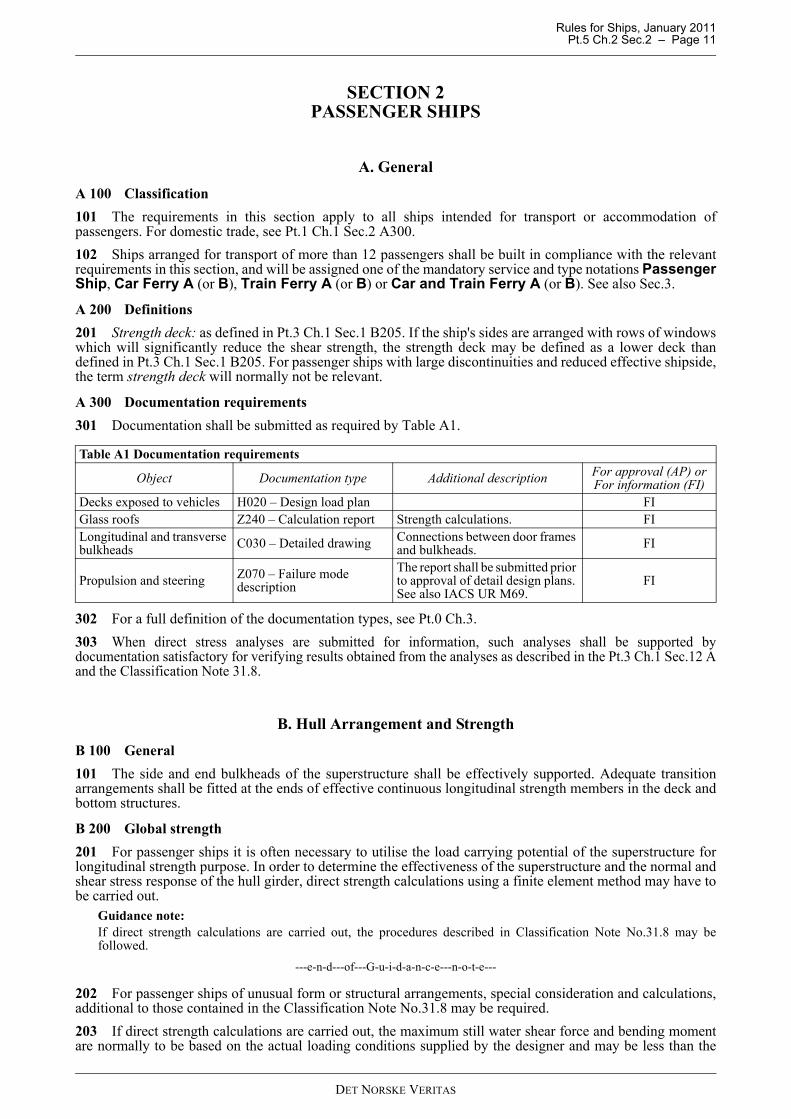
A 300 Documentation requirements301 Documentation shall be submitted as required by Table A1.
302 For a full definition of the documentation types, see Pt.0 Ch.3.303 When direct stress analyses are submitted for information, such analyses shall be supported bydocumentation satisfactory for verifying results obtained from the analyses as described in the Pt.3 Ch.1 Sec.12 Aand the Classification Note 31.8.
B. Hull Arrangement and StrengthB 100 General101 The side and end bulkheads of the superstructure shall be effectively supported. Adequate transitionarrangements shall be fitted at the ends of effective continuous longitudinal strength members in the deck andbottom structures.
B 200 Global strength201 For passenger ships it is often necessary to utilise the load carrying potential of the superstructure forlongitudinal strength purpose. In order to determine the effectiveness of the superstructure and the normal andshear stress response of the hull girder, direct strength calculations using a finite element method may have tobe carried out.
Guidance note:If direct strength calculations are carried out, the procedures described in Classification Note No.31.8 may befollowed.
---e-n-d---of---G-u-i-d-a-n-c-e---n-o-t-e---
202 For passenger ships of unusual form or structural arrangements, special consideration and calculations,additional to those contained in the Classification Note No.31.8 may be required.203 If direct strength calculations are carried out, the maximum still water shear force and bending momentare normally to be based on the actual loading conditions supplied by the designer and may be less than the
Table A1 Documentation requirements
Object Documentation type Additional description For approval (AP) orFor information (FI)
Decks exposed to vehicles H020 – Design load plan FIGlass roofs Z240 – Calculation report Strength calculations. FILongitudinal and transverse bulkheads C030 – Detailed drawing Connections between door frames
and bulkheads. FI
Propulsion and steering Z070 – Failure mode description
The report shall be submitted prior to approval of detail design plans. See also IACS UR M69.
FI
DET NORSKE VERITAS
Rules for Ships, January 2011 Pt.5 Ch.2 Sec.2 – Page 12
values specified in Pt.3 Ch.1 Sec.5 B100. The maximum values from all loading conditions, calculated at eachposition along the ship, shall be used to define the still water shear force and bending moment envelope limitcurves.
Guidance note:It is recommended that the envelope limit curves include a margin of 5-8% to give allowance for possible changes tothe design.
---e-n-d---of---G-u-i-d-a-n-c-e---n-o-t-e---
204 For ships with large openings or discontinuities in the midship area, the design still water shear force (inthis area) will be specially considered. The factor ksq as defined by Pt.3 Ch.1 Sec.5 B shall not be taken less than 0.5 between 0.4L and 0.6 L from AP. Direct strength analyses, where the design shear force envelope limit curve is applied together with the waveshear force distribution, may be required.
205 If documented that the vessel will never be in a still water sagging condition, the maximum designsagging still water moment may be taken as the minimum actual hogging bending moment.
206 The envelope limit curves used as basis for the design shall be included in the loading manual andloading computer system as permissible limits for the vessel.
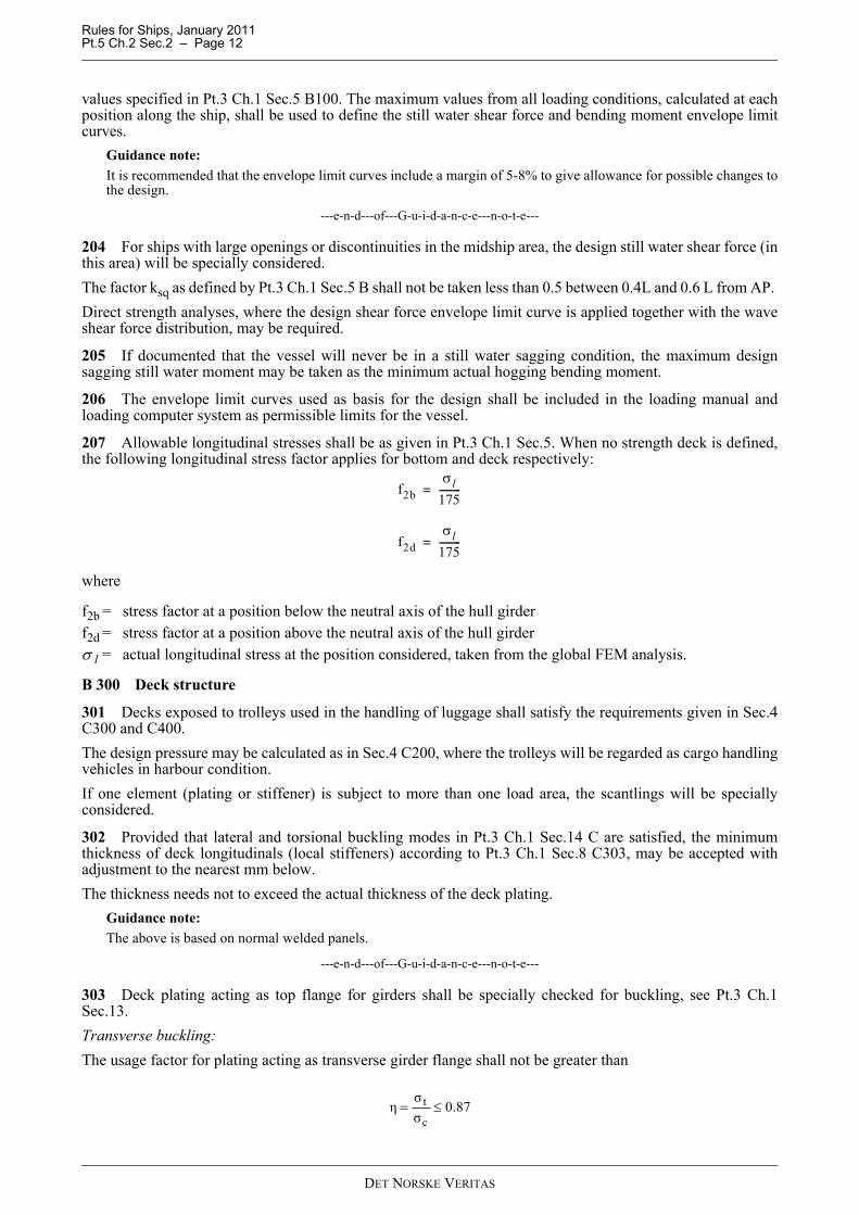
207 Allowable longitudinal stresses shall be as given in Pt.3 Ch.1 Sec.5. When no strength deck is defined,the following longitudinal stress factor applies for bottom and deck respectively:
where
f2b = stress factor at a position below the neutral axis of the hull girderf2d = stress factor at a position above the neutral axis of the hull girderσ l = actual longitudinal stress at the position considered, taken from the global FEM analysis.
B 300 Deck structure
301 Decks exposed to trolleys used in the handling of luggage shall satisfy the requirements given in Sec.4C300 and C400. The design pressure may be calculated as in Sec.4 C200, where the trolleys will be regarded as cargo handlingvehicles in harbour condition. If one element (plating or stiffener) is subject to more than one load area, the scantlings will be speciallyconsidered.
302 Provided that lateral and torsional buckling modes in Pt.3 Ch.1 Sec.14 C are satisfied, the minimumthickness of deck longitudinals (local stiffeners) according to Pt.3 Ch.1 Sec.8 C303, may be accepted withadjustment to the nearest mm below. The thickness needs not to exceed the actual thickness of the deck plating.
Guidance note:The above is based on normal welded panels.
---e-n-d---of---G-u-i-d-a-n-c-e---n-o-t-e---
303 Deck plating acting as top flange for girders shall be specially checked for buckling, see Pt.3 Ch.1Sec.13.Transverse buckling:The usage factor for plating acting as transverse girder flange shall not be greater than
f2bσl
175---------=
f2dσl
175---------=
0.87σσ
ηc
t ≤=
DET NORSKE VERITAS

Rules for Ships, January 2011 Pt.5 Ch.2 Sec.2 – Page 13
Longitudinal buckling:The usage factor for plating acting as longitudinal girder flange is given by
or
σ MS, σ MW as defined in Pt.3 Ch.1 Sec.5σ l is longitudinal stress in deck.
B 400 Pillars401 When direct strength calculations are carried out, the axial load component from global bending shall betaken into consideration when determining the nominal axial force in pillars.402 The compressive forces in the pillars shall in general be checked against the critical buckling loadcalculated from the Rules Pt.3 Ch.1 Sec.13 C. When the axial load component from global bending is taken into consideration in combination with local deckforces as described in Pt.3 Ch.1 Sec.13 C204, k may be taken as 0.9.403 The acceptable axial stress for pillars in tension is:
σ = 160 f1 (MPa)The local support of tension exposed pillars shall be specially considered. Full penetration welds shall normallybe arranged at the ends.404 Direct stress analyses of deck and bottom structure in way of pillars may be necessary.
B 500 Cofferdam structure501 Diaphragm plates in cofferdams surrounding tanks shall be specially checked for buckling. Allapplicable local loads in tank boundaries are given in Pt.3 Ch.1 Sec.9 Table B1. However, the formula takinginto account the air pipe height shall be replaced by the following formula for buckling check:
p = ρg0hp + ΔpdynGuidance note:The requirement is based on experience with cofferdams surrounding fuel oil and fresh water tanks in passenger ships.The shear buckling capacity of the diaphragms in the cofferdam structure is often critical for these structures, anddetails like openings need special consideration.
---e-n-d---of---G-u-i-d-a-n-c-e---n-o-t-e---
502 The thickness of plating in diaphragm structure shall satisfy the buckling strength requirements given inPt.3 Ch.1 Sec.13, taking into account also combination of shear and compressive in-plane stresses whererelevant.
B 600 Movable glass roofs601 The minimum forces acting on the glass roof and the supporting structure shall normally be taken as:Vertical force:
pv = q (g0 + 0.5av) (kN/m2)Pv = pAvq = minimum 0.15 t/m2 + self weight of glass roofav = vertical acceleration according to Pt.3 Ch.1 Sec.4Av = vertical projection of glass roof.Transverse force on side walls:
pT = 2.5 kN/m2 PT = pATAT= vertical projection of glass roof.Loads for horizontal stoppers:combine PVC = qg0 Av with PT
0.1c
lMWMS ≤σ
σ+σ+σ=η
87.059.0
c
lMWMS ≤σ
σ+σ+σ=η
DET NORSKE VERITAS

Rules for Ships, January 2011 Pt.5 Ch.2 Sec.2 – Page 14
602 Allowable nominal stresses:
σ = 160f1 (MPa)τ = 90f1 (MPa)
603 The roof shall not be opened when the wind speed exceeds 15 m/sec. This restriction shall be stated inthe operation manual for the vessel.
604 The stoppers and locking devices shall be provided such that in the event of failure of the hydraulicsystem the roof will remain in position.
B 700 Windows and glass structure
701 The design load shall be in accordance with the rules as given in Pt.3 Ch.1 Sec.10 C100. Design pressureon windows located at front bulkheads above navigation bridge is taken as minimum 7.5 kN/m2, provided thatthe location is above 4th tier.
702 Required glass thickness is calculated according to Pt.3 Ch.3 Sec.6 L202. Minimum glass thicknessgiven in item 2) may be especially considered for glass doors and walls located in protected areas at sides andaft ends, 1.7 Cw (m) or more above S.W.L.
B 800 Fatigue
801 For ro-pax vessels, which are mainly intended for transport of cargo and with limited numbers ofpassengers, the racking strength and corresponding fatigue evaluation shall be considered
Guidance note:This may be carried out in accordance with Classification Note 31.8.
---e-n-d---of---G-u-i-d-a-n-c-e---n-o-t-e---
802 Due attention shall be made to fatigue strength of structural details. Details with high stressconcentrations due to longitudinal or racking transverse stresses shall be specially assessed with respect tofatigue.
Guidance note:Classification Note no.31.8 describes acceptable loads and procedures for such analyses.
---e-n-d---of---G-u-i-d-a-n-c-e---n-o-t-e---
803 In way of stress concentration areas, increased radius, edge reinforcement and inserts with increasedplate thickness may have to be applied for keeping notch effects and stress concentrations at acceptable levels.
Guidance note:Areas normally to be considered with respect to fatigue are openings in ship side, longitudinal bulkheads and upperdecks.
---e-n-d---of---G-u-i-d-a-n-c-e---n-o-t-e---
804 In way of corner regions of openings for doors and windows, welding shall in general be avoided. Ifwelds in these areas cannot be avoided completely, the details need special consideration as the maximumallowable peak stress due to fatigue then will drop considerably.
C. Machinery and Systems
C 100 General
101 For ships with class notation Passenger Ship the machinery and systems are in general to be asrequired for the main class.
Guidance note:Requirements to bilge pumping in passenger ships are given in SOLAS Reg. II-1/21.2
---e-n-d---of---G-u-i-d-a-n-c-e---n-o-t-e---
102 Electrical distribution systems shall be so arranged that fire in any main vertical zone, as defined in Pt.4Ch.10, will not interfere with services essential for safety in any other such zone. This requirement will be metif main and emergency feeders passing through any such zone are separated both vertically and horizontally aswidely as is practicable.
DET NORSKE VERITAS
Rules for Ships, January 2011 Pt.5 Ch.2 Sec.2 – Page 15
D. Emergency Source of Electrical Power and Emergency Installations
D 100 General
101 Statutory text that has been adopted in the rules will be written in normal rule text font (not italics) witha reference to the corresponding statutory regulation. Adopting statutory requirements by reference alone willnot be used. Statutory requirements that are outside the scope of class but important to consider in associationwith the rules shall in some cases be referred to in Guidance notes.
102 A self-contained emergency source of electrical power shall be provided.
103 The emergency source of electrical power, associated transforming equipment, if any, transitional sourceof emergency power, emergency switchboard and emergency lighting switchboard shall be located above theuppermost continuous deck and shall be readily accessible from the open deck. They shall not be locatedforward of the collision bulkhead.
104 The location of the emergency source of electrical power and associated transforming equipment, if any,the transitional source of emergency power, the emergency switchboard and the emergency electric lightingswitchboards in relation to the main source of electrical power, associated transforming equipment, if any, andthe main switchboard shall be such as to ensure to the satisfaction of the Administration that a fire or othercasualty in spaces containing the main source of electrical power, associated transforming equipment, if any,and the main switchboard or in any machinery space of category A will not interfere with the supply, controland distribution of emergency electrical power. As far as practicable, the space containing the emergencysource of electrical power, associated transforming equipment, if any, the transitional source of emergencyelectrical power and the emergency switchboard shall not be contiguous to the boundaries of machinery spacesof category A or those spaces containing the main source of electrical power, associated transformingequipment, if any, or the main switchboard.
105 Provided that suitable measures are taken for safeguarding independent emergency operation under allcircumstances, the emergency generator may be used exceptionally, and for short periods, to supply non-emergency circuits.Non essential domestic supplies should not be directly connected to the emergency switchboard.
D 200 Services to be supplied
201 The electrical power available shall be sufficient to supply all those services that are essential for safetyin an emergency, due regard being paid to such services as may have to be operated simultaneously. Theemergency source of electrical power shall be capable, having regard to starting currents and the transitorynature of certain loads, of supplying simultaneously at least the following services for the periods specifiedhereinafter, if they depend upon an electrical source for their operation, as stated in the following items 202 to207.
202 For a period of 36 hours, emergency lighting:
1) at every muster and embarkation station and over the sides as required by regulations III/11.4 and III/16.7; 2) in alleyways, stairways and exits giving access to the muster and embarkation stations, as required by
regulation III/11.5;3) in all service and accommodation alleyways, stairways and exits, personnel lift cars;4) in the machinery spaces and main generating stations including their control positions;5) in all control stations, machinery control rooms, and at each main and emergency switchboard;6) at all stowage positions for firemen's outfits;7) at the steering gear; and8) at the fire pump, the sprinkler pump and the emergency bilge pump referred to in 205 and at the starting
position of their motors.
203 For a period of 36 hours:
1) the navigation lights and other lights required by the International Regulations for Preventing Collisions atSea in force; and
2) the VHF radio installation required by regulation IV/7.1.1 and IV/7.1.2; and, if applicable:
— 2.1 the MF radio installation required by regulations IV/12.1.1, IV/12.1.2, IV/10.1.2 and IV/10.1.3;— 2.2 the ship earth station required by regulation IV/10.1.1.; and— 2.3 the MF/HF radio installation required by regulations IV/10.2.1, IV/10.2.2 and IV/11.1.
DET NORSKE VERITAS
Rules for Ships, January 2011 Pt.5 Ch.2 Sec.2 – Page 16
204 For a period of 36 hours:
1) all internal communication equipment required in an emergencyshall include:
— The means of communication which is provided between the navigating bridge and the steering gearcompartment.
— The means of communication which is provided between the navigating bridge and the position in themachinery space or control room from which the engines are normally controlled.
— The means of communication which is provided between the bridge and the radio telegraph or radiotelephone stations.
— The means of communication which is provided between the officer of the watch and the personresponsible for closing any watertight door which is not capable of being closed from a central controlstation.
— The public address system or other effective means of communication which is provided throughoutthe accommodation, public and service spaces.
— The means of communication which is provided between the navigating bridge and the main firecontrol station;
2) the shipborne navigational equipment as required by regulation V/12.3) the fire detection and fire alarm system, and the fire door holding and release system; and4) for intermittent operation of the daylight signalling lamp, the ship's whistle, the manually operated call
points and all internal signals that are required in an emergency;
unless such services have an independent supply for the period of 36 hours from an accumulator batterysuitably located for use in an emergency.205 For a period of 36 hours:
1) one of the fire pumps required by regulation II-2/4.3.1 and 4.3.3;2) the automatic sprinkler pump, if any; and3) the emergency bilge pump, and all the equipment essential for the operation of electrically powered remote
controlled bilge valves.
206 For the period of time required by regulation 29.14 (Pt.4 Ch.14 Sec.1 E300) the steering gear if requiredto be so supplied by that subsection.207 For a period of half an hour:
1) any watertight doors required by SOLAS Reg. II-1/15 to be power operated together with their indicatorsand warning signals.
2) the emergency arrangements to bring the lift cars to deck level for the escape of persons. The passenger liftcars may be brought to deck level sequentially in an emergency.
208 In a ship engaged regularly on voyages of short duration, the Administration if satisfied that an adequatestandard of safety would be attained may accept a lesser period than the 36 hour period specified in items 202 to206 but not less than 12 hours.
D 300 Arrangement of emergency source(s) of power301 The emergency source of electrical power may be either a generator or an accumulator battery, whichshall comply with the following:302 Where the emergency source of electrical power is a generator, it shall be:
1) driven by a suitable prime-mover with an independent supply of fuel having a flashpoint (closed cup test)of not less than 43°C;
2) started automatically upon failure of the electrical supply from the main source of electrical power and shallbe automatically connected to the emergency switchboard; those services referred to in 400 shall then betransferred automatically to the emergency generating set. The automatic starting system and thecharacteristic of the prime-mover shall be such as to permit the emergency generator to carry its full ratedload as quickly as is safe and practicable, subject to a maximum of 45 seconds; unless a second independentmeans of starting the emergency generating set is provided, the single source of stored energy shall beprotected to preclude its complete depletion by the automatic starting system; and
3) provided with a transitional source of emergency electrical power according to 400.
303 Where the emergency source of electrical power is an accumulator battery, it shall be capable of:
DET NORSKE VERITAS
Rules for Ships, January 2011 Pt.5 Ch.2 Sec.2 – Page 17
1) carrying the emergency electrical load without recharging while maintaining the voltage of the batterythroughout the discharge period within 12 per cent above or below its nominal voltage;
2) automatically connecting to the emergency switchboard in the event of failure of the main source ofelectrical power; and
3) immediately supplying at least those services specified in 400.
D 400 Transitional source of emergency power401 The transitional source of emergency electrical power required by item 302.3) shall consist of anaccumulator battery suitably located for use in an emergency which shall operate without recharging whilemaintaining the voltage of the battery throughout the discharge period within 12 per cent above or below itsnominal voltage and be of sufficient capacity and so arranged as to supply automatically in the event of failureof either the main or emergency source of electrical power at least the following services, if they depend uponan electrical source for their operation:402 For half an hour:
1) the lighting required by items 202 and 203.1;2) all services required by items 204.1), 204.3) and 204.4), unless such services have an independent supply
for the period specified from an accumulator battery suitably located for use in an emergency.
403 Power to operate the watertight doors, as required by SOLAS Reg. II-1/15, but not necessarily all of themsimultaneously, unless an independent temporary source of stored energy is provided. Power to the control,indication and alarm circuits as required by SOLAS Reg. II-1/15, for half an hour.
D 500 Low-location lighting501 Passenger ships shall be provided with low-location lighting (LLL) complying with IMO Res.A.752(18).
D 600 Supplementary lighting 601 In passenger ships, supplementary lighting shall be provided in all cabins to clearly indicate the exit sothat occupants will be able to find their way to the door. Such lighting, which may be connected to anemergency source of power or have a self-contained source of electrical power in each cabin, shallautomatically illuminate when power to the normal cabin lighting is lost and remain on for a minimum of 30min. (Reg. 11-1/41.6)602 For ro-ro passenger ships (Reg. 11-1/42-1), in addition to the emergency lighting required by regulation42.2 (200), on every passenger ship with ro-ro cargo spaces or special category spaces as defined in regulation11-213 (F101):
1) all passenger public spaces and alleyways shall be provided with supplementary electric lighting that canoperate for at least three hours when all other sources of electric power have failed and under any conditionof heel. The illumination provided shall be such that the approach to the means of escape can be readilyseen. The source of power for the supplementary lighting shall consist of accumulator batteries locatedwithin the lighting units that are continuously charged, where practicable, from the emergencyswitchboard. Alternatively, any other means of lighting which is at least as effective may be accepted bythe Administration. The supplementary lighting shall be such that any failure of the lamp will beimmediately apparent. Any accumulator battery provided shall be replaced at intervals having regard to thespecified service life in the ambient conditions that they are subject to in service; and
2) a portable rechargeable battery operated lamp shall be provided in every crew space alleyway, recreationalspace and every working space which is normally occupied unless supplementary emergency lighting, asrequired by sub paragraph.1, is provided.
D 700 Location of emergency switchboard, distribution701 The emergency switchboard shall be installed as near as is practicable to the emergency source ofelectrical power.702 Where the emergency source of electrical power is a generator, the emergency switchboard shall belocated in the same space unless the operation of the emergency switchboard would thereby be impaired.703 No accumulator battery fitted in accordance with this Regulation shall be installed in the same space asthe emergency switchboard. An indicator shall be mounted in a suitable place on the main switchboard or inthe machinery control room to indicate when the batteries constituting either the emergency source of electricalpower or the transitional source of emergency electrical power referred to in item 302.3) or 400 are beingdischarged.704 The emergency switchboard shall be supplied during normal operation from the main switchboard by an
DET NORSKE VERITAS
Rules for Ships, January 2011 Pt.5 Ch.2 Sec.2 – Page 18
interconnector feeder which shall be adequately protected at the main switchboard against overload and shortcircuit and which shall be disconnected automatically at the emergency switchboard upon failure of the mainsource of electrical power. Where the system is arranged for feedback operation, the interconnector feeder isalso to be protected at the emergency switchboard at least against short circuit.705 In order to ensure ready availability of the emergency source of electrical power, arrangements shall bemade where necessary to disconnect automatically non-emergency circuits from the emergency switchboardto ensure that power shall be available to the emergency circuits.706 The arrangement of the emergency electric lighting system shall be such that a fire or other casualty inspaces containing the emergency source of electrical power, associated transforming equipment, if any, theemergency switchboard and the emergency lighting switchboard will not render the main electric lightingsystem required by this regulation (Pt.4 Ch.8 Sec.2 I102 b) inoperative.See also Pt.4 Ch.8 Sec.2 F.
D 800 Inclinations (list and trim of ship)801 The emergency generator and its prime-mover and any emergency accumulator battery shall be sodesigned and arranged as to ensure that they will function at full rated power when the ship is upright and wheninclined at any angle of list up to 22.5° or when inclined up to 10° either in the fore or aft direction, or is in anycombination of angles within those limits.
D 900 Periodical testing901 Provision shall be made for the periodic testing of the complete emergency system and shall include thetesting of automatic starting arrangements.
D 1000 Starting arrangements for emergency generating sets1001 Starting arrangements for emergency generating sets shall comply with the requirements given forcargo ships in Pt.4 Ch.8 Sec.2 C300.
E. Fire Safety Measures for Passenger Ships
E 100 Application101 The requirements for fire protection in this section apply to any ship which carries more than twelvepassengers.
E 200 Rule references and definitions201 These requirements are given in addition to those applicable for the main class, as given in Pt.4 Ch.10.202 For fire technical and space definitions, see Pt.4 Ch.10.
E 300 Documentation301 The following plans and particulars shall be submitted for approval:
— General arrangement plan showing main vertical zone arrangement including steps and recesses, stairwaysand doors.
— Arrangement of means of escape from different compartments and escape calculations.
E 400 Main vertical zones and horizontal zones (SOLAS Reg. II-2/9.2.2.1)401 In ships carrying more than 36 passengers, the hull, superstructure and deckhouses shall be subdividedinto main vertical zones by “A-60” class divisions. Steps and recesses shall be kept to a minimum but wherethey are necessary, they shall also be “A-60” class divisions. Open deck spaces, sanitary or similar spaces,tanks, voids and auxiliary machinery spaces having little or no fire risk on one side or where fuel oil tanks areon both sides of the division the standard may be reduced to “A-0”.402 In ships carrying not more than 36 passengers, the hull, superstructure and deckhouses in way ofaccommodation and service spaces shall be subdivided into main vertical zones by “A” class divisions.403 As far as practicable, the bulkheads forming the boundaries of the main vertical zones above thebulkhead deck shall be in line with watertight subdivision bulkheads situated immediately below the bulkheaddeck. The length and width of main vertical zones may be extended to a maximum of 48 m in order to bringthe ends of main vertical zones to coincide with watertight subdivision bulkheads or in order to accommodatea large public space extending for the whole length of the main vertical zone provided that the total area of themain vertical zone is not greater than 1 600 m2 on any deck. The length or width of a main vertical zone is themaximum distance between the furthermost points of the bulkheads bounding it.
DET NORSKE VERITAS
Rules for Ships, January 2011 Pt.5 Ch.2 Sec.2 – Page 19
404 Such bulkheads shall extend from deck to deck and to the shell or other boundaries.405 Where a main vertical zone is subdivided by horizontal “A” class divisions into horizontal zones for thepurpose of providing an appropriate barrier between a zone with sprinklers and a zone without sprinklers, thedivisions shall extend between adjacent main vertical zone bulkheads and to the shell or exterior boundaries ofthe ship.406 On ships designed for special purposes, such as automobile or railroad car ferries, where the provisionof main vertical zone bulkheads would defeat the purpose for which the ship is intended, equivalent means forcontrolling and limiting a fire shall be substituted and specifically approved by the Society. Service spaces andship stores shall not be located on ro-ro decks unless protected in accordance with the applicable requirements.407 However, in a ship with special category spaces, any such space shall comply with the applicablerequirements to such spaces and where such compliance would be inconsistent with other requirements forpassenger ships specified in this Part, the requirements for special category spaces shall prevail.408 The basic principle underlying the provisions of this paragraph is that the main vertical zoning requiredby 401 and 402 may not be practicable in vehicle spaces of passenger ships and, therefore, equivalent protectionshall be obtained in such spaces on the basis of a horizontal zone concept and by the provision of an efficientfixed fire-extinguishing system. Based on this concept, a horizontal zone may include special category spaceson more than one deck provided that the total overall clear height for vehicles does not exceed 10 m.(SOLAS Reg. II-2/20.2.2.1)409 The basic principle underlying the provisions of paragraph 408 is also applicable to ro-ro spaces. (SOLAS Reg. II-2/20.2.2.2)
E 500 Protection of stairways and lifts in accommodation area (SOLAS Reg. II-2/9.2.2.5)501 Stairways shall be within enclosures formed of “A” class divisions, with positive means of closure at allopenings, except that:
.1 a stairway connecting only two decks need not be enclosed, provided the integrity of the deck is maintainedby proper bulkheads or self-closing doors in one 'tween-deck space. When a stairway is closed in one'tween-deck space, the stairway enclosure shall be protected in accordance with the requirements for decks;and
.2 stairways may be fitted in the open in a public space, provided they lie wholly within the public space.502 Lift trunks shall be so fitted as to prevent the passage of smoke and flame from one ‘tween-deck toanother and shall be provided with means of closing so as to permit the control of draught and smoke.Machinery for lifts located within stairway enclosures shall be arranged in a separate room, surrounded by steelboundaries, except that small passages for lift cables are permitted. Lifts which open into spaces other thancorridors, public spaces, special category spaces, stairways and external areas shall not open into stairwaysincluded in the means of escape.
E 600 Means of escape from accommodation spaces, service spaces and control stations (SOLAS Reg. II-2/13.3.2.1 - 13.3.2.4)601 Below the bulkhead deck two means of escape, at least one of which shall be independent of watertightdoors, shall be provided from each watertight compartment or similarly restricted space or group of spaces.Exceptionally, the Society may dispense with one of the means of escape for crew spaces that are entered onlyoccasionally, if the required escape route is independent of watertight doors.602 Where the Society has granted dispensation under the provisions of 601, this sole means of escape shallprovide safe escape. However, stairways shall not be less than 800 mm in clear width with handrails on bothsides.603 Above the bulkhead deck there shall be at least two means of escape from each main vertical zone orsimilarly restricted space or group of spaces at least one of which shall give access to a stairway forming avertical escape.604 Stairway enclosures in accommodation and service spaces shall have direct access from the corridors andbe of a sufficient area to prevent congestion, having in view the number of persons likely to use them in anemergency. Within the perimeter of such stairway enclosures, only public toilets, lockers of non-combustiblematerial providing storage for non-hazardous safety equipment and open information counters are permitted.Only public spaces, corridors, lifts, public toilets, special category spaces and open ro-ro spaces to which anypassengers carried can have access, other escape stairways required by 605 and external areas are permitted tohave direct access to these stairway enclosures. Small corridors or “lobbies” used to separate an enclosedstairway from galleys or main laundries may have direct access to the stairway provided they have a minimumdeck area of 4.5 m2, a width of no less than 900 mm and contain a fire hose station.605 At least one of the means of escape required by 601 and 603 shall consist of a readily accessible enclosed
DET NORSKE VERITAS
Rules for Ships, January 2011 Pt.5 Ch.2 Sec.2 – Page 20
stairway, which shall provide continuous fire shelter from the level of its origin to the appropriate lifeboat andliferaft embarkation decks, or to the uppermost weather deck if the embarkation deck does not extend to themain vertical zone being considered. In the latter case, direct access to the embarkation deck by way of externalopen stairways and passageways shall be provided and shall have emergency lighting and slip-free surfacesunderfoot. Boundaries facing external open stairways and passageways forming part of an escape route andboundaries in such a position that their failure during a fire would impede escape to the embarkation deck shallhave fire integrity, including insulation values, in accordance with appropriate requirements.606 Protection of access from the stairway enclosures to the lifeboat and liferaft embarkation areas shall beprovided either directly or through protected internal routes which have fire integrity and insulation values asrequired for stairway enclosures.607 Stairways serving only a space and a balcony in that space shall not be considered as forming one of therequired means of escape.608 Each level within an atrium shall have two means of escape, one of which shall give direct access to anenclosed vertical means of escape meeting the requirements of 605.609 The widths, number and continuity of escapes shall be in accordance with the requirements in the FireSafety Systems Code.
E 700 Means of escape from machinery spaces (SOLAS Reg. II-2/13.4.1)701 Where the space is below the bulkhead deck the two means of escape shall consist of either:
.1 two sets of steel ladders as widely separated as possible, leading to doors in the upper part of the spacesimilarly separated and from which access is provided to the appropriate lifeboat and liferaft embarkationdecks. One of these ladders shall be located within a protected enclosure from the lower part of the spaceit serves to a safe position outside the space. Self-closing fire doors of the same fire integrity standards shallbe fitted in the enclosure. The ladder shall be fixed in such a way that heat is not transferred into theenclosure through non-insulated fixing points. The protected enclosure shall have minimum internaldimensions of at least 800 mm × 800 mm, and shall have emergency lighting provisions; or
.2 one steel ladder leading to a door in the upper part of the space from which access is provided to theembarkation deck and additionally, in the lower part of the space and in a position well separated from theladder referred to, a steel door capable of being operated from each side and which provides access to asafe escape route from the lower part of the space to the embarkation deck.
702 Where the space is above the bulkhead deck, the two means of escape shall be as widely separated aspossible and the doors leading from such means of escape shall be in a position from which access is providedto the appropriate lifeboat and liferaft embarkation decks. Where such means of escape require the use ofladders, these shall be of steel.703 In a ship of less than 1 000 gross tonnage, the Society may dispense with one of the means of escape, dueregard being paid to the width and disposition of the upper part of the space. In a ship of 1 000 gross tonnageand above, the Society may dispense with one means of escape from any such space, including a normallyunattended auxiliary machinery space, so long as either a door or a steel ladder provides a safe escape route tothe embarkation deck, due regard being paid to the nature and location of the space and whether persons arenormally employed in that space. In the steering gear space, a second means of escape shall be provided whenthe emergency steering position is located in that space unless there is direct access to the open deck.704 Two means of escape shall be provided from a machinery control room located within a machineryspace, at least one of which shall provide continuous fire shelter to a safe position outside the machinery space.
E 800 Means of escape from special category and open ro-ro spaces to which any passengers carried can have access (SOLAS Reg. II-2/13.5)801 In special category and open ro-ro spaces to which any passengers carried can have access, the numberand locations of the means of escape both below and above the bulkhead deck shall be to the satisfaction of theSociety and, in general, the safety of access to the embarkation deck shall be at least equivalent to that providedfor under 601, 603, 605 and 606. Such spaces shall be provided with designated walkways to the means ofescape with a breadth of at least 600 mm. The parking arrangements for the vehicles shall maintain thewalkways clear at all times.802 One of the escape routes from the machinery spaces where the crew is normally employed shall avoiddirect access to any special category space.
E 900 Additional requirements to means of escape for ro-ro passenger ships901 Escape routes shall be provided from every normally occupied space on the ship to an assembly station.These escape routes shall be arranged so as to provide the most direct route possible to the assembly station,and shall be marked with symbols.
DET NORSKE VERITAS
Rules for Ships, January 2011 Pt.5 Ch.2 Sec.2 – Page 21
(SOLAS Reg. II-2/13.7.1.1)Guidance note:Refer to “Symbols related to life-saving appliances and arrangements” adopted by IMO by Res. A.760(18).
---e-n-d---of---G-u-i-d-a-n-c-e---n-o-t-e---
902 The escape route from cabins to stairway enclosures shall be as direct as possible, with a minimum numberof changes in direction. It shall not be necessary to cross from one side of the ship to the other to reach an escaperoute. It shall not be necessary to climb more than two decks up or down in order to reach an assembly station oropen deck from any passenger space.(SOLAS Reg. II-2/13.7.1.2)903 External routes shall be provided from open decks, as referred to in 902, to the survival craft embarkationstations.(SOLAS Reg. II-2/13.7.1.3)904 Where enclosed spaces adjoin an open deck, openings from the enclosed space to the open deck are,where practicable, to be capable of being used as emergency exits.(SOLAS Reg. II-2/13.7.1.4)905 Escape routes shall not be obstructed by furniture and other obstructions. With the exception of tablesand chairs which may be cleared to provide open space, cabinets and other heavy furnishings in public spacesand along escape routes shall be secured in place to prevent shifting if the ship rolls or lists. Floor coveringsare also to be secured in place. When the ship is underway, escape routes shall be kept clear of obstructionssuch as cleaning carts, bedding, luggage and boxes of goods.(SOLAS Reg. II-2/13.7.1.5)906 Escape routes shall be evaluated by an evacuation analysis early in the design process. The analysis shallbe used to identify and eliminate, as far as practicable, congestion which may develop during an abandonment,due to normal movement of passengers and crew along escape routes, including the possibility that crew mayneed to move along these routes in a direction opposite the movement of passengers. In addition, the analysisshall be used to demonstrate that escape arrangements are sufficiently flexible to provide for the possibility thatcertain escape routes, assembly stations, embarkation stations or survival craft may not be available as a resultof a casualty.(SOLAS Reg. II-2/13.7.4)
Guidance note:Refer to the “Interim Guidelines for a Simplified Evacuation Analysis on Ro-Ro Passenger Ships” developed by IMO(MSC/Circ.909)
---e-n-d---of---G-u-i-d-a-n-c-e---n-o-t-e---
F. Stability and Watertight IntegrityF 100 Application101 Ships with class notation Passenger Ship shall comply with the requirements according to 300 and400.102 The class requirements may be considered complied with when a national authority has carried out theapproval in accordance with the SOLAS Ch. II-1 as amended. 103 For ships in domestic trade and with service restrictions, alternative stability requirements may beaccepted after considerations in each separate case.
Guidance note:Ships having a lesser Subdivision and stability standard than corresponding to the European Union (EU) CouncilDirective 98/18/EC of 17 march 1998 will generally not be accepted.
---e-n-d---of---G-u-i-d-a-n-c-e---n-o-t-e---
F 200 Documentation201 The following documentation shall be submitted for approval:
— preliminary damage stability calculations— final damage stability calculations— damage control plan— internal watertight integrity plan including definition of subdivision limits as applied in the calculations.
DET NORSKE VERITAS
Rules for Ships, January 2011 Pt.5 Ch.2 Sec.2 – Page 22
Guidance note:The internal watertight integrity plan(s) should clearly show the location of pipes, valves and ducts with theirrespective closing appliances.
---e-n-d---of---G-u-i-d-a-n-c-e---n-o-t-e---
F 300 Intact stability301 Passenger ships shall comply with Pt.3 Ch.3 Sec.9 with the supplementing requirements as given in 302to 304.302 Loading conditionsThe following standard loading conditions shall be included:
— ship in the fully loaded departure condition with full cargo, stores and fuel and the full number ofpassengers and their luggage
— ship with full stores and fuel and the full number of passengers and their luggage, but without cargo— ship in the fully loaded arrival condition, with full cargo and the full number of passengers and their
luggage but with only 10% stores and fuel remaining— ship with only 10% stores and fuel and the full number of passengers and their luggage, but without cargo.
303 Additional criteria
— the angle of heel on account of crowding of passengers to one side shall not exceed 10 degrees— the angle of heel on account of turning should not exceed 10 degrees when calculated using the following
formula:
MR = 0.02 Vo2 D (KG − d/2)/L
MR = heeling moment (tm)Vo = service speed (m/s)L = length of ship at waterline (m)D = displacement (t)d = draught (m)KG = height of centre of gravity above keel (m).
304 When applying the additional criteria in 303 the following shall be assumed:
1) A mass of 75 kg shall be assumed for each passenger except that this value may be reduced to not less than60 kg where this can be justified. In addition, the mass and distribution of the luggage shall be taken intoaccount.
2) The height of the centre of gravity for the passengers shall be assumed equal to:
— 1.0 m above deck level for passengers standing upright. Account may be taken, if necessary, of camberand sheer of deck
— 0.3 m above the seat in respect of seated passengers.
3) Passengers without luggage shall be considered as distributed to produce the most unfavourablecombination of passenger heeling moment and or initial metacentric height, which may be obtained inpractice. A value of not less than 4 persons per square metre shall be applied.
F 400 Subdivision and damage stability401 Passenger ships shall comply with the applicable regulations of SOLAS Ch. II-1, as amended.
DET NORSKE VERITAS
Rules for Ships, January 2011 Pt.5 Ch.2 Sec.3 – Page 23
SECTION 3 FERRIES
A. GeneralA 100 Classification101 The requirements in this section apply to ships intended for regular transport of passengers and vehicles.The requirements for passenger ships given in Sec.2 are also to be complied with.102 Ships arranged for carriage of vehicles on enclosed decks and built in compliance with relevantrequirements specified in the following will be given one of the class notations Car Ferry A, Train Ferry Aor Car and Train Ferry A whichever is applicable.103 Ships arranged for carriage of vehicles on weather deck only and built in compliance with relevantrequirements specified in the following will be given one of the class notations Car Ferry B, Train Ferry Bor Car and Train Ferry B whichever is applicable.
A 200 Assumptions201 The requirements for the class notation B are based on the assumption that service restriction notationR2 or stricter are included in the main class.
A 300 Documentation301 The following plans and particulars shall be submitted for approval:
a) Stern, side shell and bow doors (outer and inner) including force carrying structures of door cleat andsupport devices and their supporting structure of the hull.
b) Closing arrangement for doors including system for operation.c) Operating and maintenance manual for bow doors, side shell doors and stern doors.
The operating and maintenance manual shall be provided on board and shall contain necessary information on:
Main particulars and design drawings
— special safety precautions— details of vessel, class, statutory certificates— equipment and design loading (for ramps)— key plan of equipment (doors and ramps)— manufacturer's recommended testing for equipment— description of equipment
— bow doors— inner bow doors— bow ramp/doors— side doors— stern doors— central power pack— bridge panel— engine control room panel
Service conditions
— limiting heel and trim of ship for loading/unloading— limiting heel and trim for door operations— doors/ramps operating instructions— doors/ramps emergency operating instructions
Maintenance
— schedule and extent of maintenance— trouble-shooting— acceptance/rejection criteria, acceptable clearances— manufacturer's maintenance procedures
Register of inspections, including:
— inspection of locking, securing and supporting devices
DET NORSKE VERITAS
Rules for Ships, January 2011 Pt.5 Ch.2 Sec.3 – Page 24
— repairs and renewals.
The operating and maintenance manual shall be submitted for approval with respect to the items listedabove being contained in the manual. In addition, the inclusion of the necessary information with regard toinspections, trouble-shooting and acceptance/rejection criteria in the maintenance part shall be verified.Guidance note:It is recommended that recorded inspections of the door supporting and securing devices be carried out by the ship's staffat monthly intervals or following incidents that could result in damage, including heavy weather or contact in the regionof the shell doors.Any damage recorded during such inspections shall be reported to the Society. This is also to be stated in the operatingand maintenance manual.
---e-n-d---of---G-u-i-d-a-n-c-e---n-o-t-e---
Guidance note:Reference is made to the safety management system described in the ISM Code.
---e-n-d---of---G-u-i-d-a-n-c-e---n-o-t-e---
d) Arrangement of accesses from the ro-ro deck (bulkhead deck) to spaces below (showing all doors, ramps,hatches etc.).
302 The following plans and particulars are normally to be submitted for information:
a) An arrangement plan showing the position of watertight doors in the stern, sides, bow and collisionbulkhead in relation to the watertight subdivision of the hull.
b) Arrangement of doors including hydraulic and mechanical supporting, cleating and locking arrangementsas relevant. For doors with clear opening >12 m2, the design support forces considered and or determinedfor each support shall be stated on the arrangement drawing and submitted together with design calculationscarried out. For bow doors the longitudinal, transverse and vertical projections shall be shown.
c) Arrangement of air intakes, ventilators etc.d) Arrangement of doors from vehicle deck.e) Drainage openings and or freeing ports for vehicle deck and space between outer and inner bow door.f) Arrangement of wheels and axles or bogies for heavy vehicles, stating maximum axle and or bogie load.g) Fastening and securing appliances of vehicles to the hull structure.h) Types of locking arrangements used on cleats and support devices on doors with clear opening > 12 m2,
(Ref. D1201).
303 Documentation for the following indication, control and monitoring systems shall be submitted forapproval:
— bow doors monitoring system— water leakage monitoring system.
For requirements to documentation types, see Pt.4 Ch.9.
A 400 Definitions401 Symbols
t = rule thickness in mm of platingZ = rule section modulus in cm3 of stiffeners and simple girderss = stiffener spacing in m, measured along the platingl = stiffener span in m, measured along the topflange of the member. For definition of span point, see Pt.3
Ch.1 Sec.3 C100. For curved stiffeners l may be taken as the cord lengthS = girder span in m. For definition of span point, see Pt.3 Ch.1 Sec.3 C100b = loading breadth for girders in mf1 = material factor
= 1.0 for NV-NS steel *)
= 1.08 for NV-27 steel *)
= 1.28 for NV-32 steel *)
= 1.39 for NV-36 steel *)
= 1.47 for NV-40 steel *)
*) For details see Pt.3 Ch.1 Sec.2 B to C402 The load point where the design pressure shall be calculated is defined for various strength members as follows:
DET NORSKE VERITAS

Rules for Ships, January 2011 Pt.5 Ch.2 Sec.3 – Page 25
a) For platesMidpoint of horizontally stiffened plate field.Half of the stiffener spacing above the lower support of vertically stiffened plate field, or at lower edge ofplate when the thickness is changed within the plate field.
b) For stiffenersMidpoint of span.When the pressure is not varied linearly over the span, the design pressure shall be taken as the greater of:
pm, pa and pb are calculated pressures at the midpoint and at each end respectively.c) For girders
Midpoint of load area.403 Ro-Ro passenger shipis a passenger ship with ro-ro spaces or special category spaces.404 Ro-Ro spacesare spaces not normally subdivided in any way and normally extending to either a substantial length or theentire length of the ship in which motor vehicles with fuel in their tanks for their own propulsion and/or goods(packaged or in bulk, in or on rail or road cars, vehicles (including road or rail tankers), trailers, containers,pallets, demountable tanks or in or on similar stowage units or other receptacles) can be loaded and unloadednormally in a horizontal direction.405 Special category spacesare those enclosed spaces above or below the bulkhead deck, into and from which vehicles can be driven andto which passengers have access.Special category spaces may be accommodated on more than one deck provided that the total overall clearheight for vehicles does not exceed 10 m.
A 500 Internal communication501 Requirement for documentation of general alarm and public address systems is given in DNV StatutoryInterpretations.
A 600 Certification of bow doors monitoring system601 The bow doors monitoring system shall be certified according to Pt.4 Ch.9.
B. Hull Arrangement and StrengthB 100 Vehicle decks, ramps and lifts101 Plating with supporting stiffeners and girders for direct wheel loads shall satisfy the requirements for theclass notation PWDK given in Sec.4 C. Decks where the free height exceed 2.5 m, shall be designed for anaxle load not less than 10 t.102 Movable car decks, if fitted, shall satisfy relevant requirements given in Sec.7.103 External ramps, internal ramps and lift platforms are also to satisfy the requirements given in Sec.4 B.104 Scantlings of decks, ramps, lifts etc. for railway carriages will be considered in each case.
B 200 Securing of vehicles201 Appliances shall be provided for securing of road vehicles and railway carriages. Strength and fasteningof the securing points shall satisfy the requirements given in Sec.4 B1200.202 For ships with restricted service notation R3, R4 or RE, the requirements with respect to securingappliances may be reduced or discarded based upon special consideration of the intended service area.
B 300 Transverse strength301 A sufficient number of vertical side girders and/or transverse bulkheads in casing(s) shall be fittedbetween the vehicle deck(s) and the superstructure above. Transverse and longitudinal bulkheads shall beeffectively supported below the vehicle deck(s). Calculations necessary to demonstrate that the stresses areacceptable, shall be carried out for the ship also in heeled conditions. Design loads, calculation methods andallowable stresses shall be as given for complex girder systems in Pt.3 Ch.1 Sec.13.
pm and pa pb+
2-----------------
DET NORSKE VERITAS

Rules for Ships, January 2011 Pt.5 Ch.2 Sec.3 – Page 26
C. Openings and Closing AppliancesC 100 Doors101 Arrangements and scantlings of doors in ship's side and ends are in general to satisfy the requirementsgiven for main class, with relevant additions as given in 102 to 402.102 Arrangement, scantlings and securing of bow doors are given in D.103 Arrangement, scantlings and securing of side and stern doors are given in Pt.3 Ch.3 Sec.6 C.104 For ferries with the class notation B, openings in sides and ends leading to the vehicle deck need not haveclosing appliances.105 Doors also used as driving ramps for vehicles shall satisfy relevant requirements given in Sec.4 B andSec.4 C.
C 200 Access openings201 Doors and sill heights are in general to satisfy the requirements given for main class.202 Doors leading from vehicle deck to engine room shall have sill heights not less than 380 mm. Other doorsleading from vehicle deck within a closed superstructure to spaces below freeboard deck, are in no case to havesill heights less than 230 mm.
C 300 Watertight integrity from the ro-ro deck (bulkhead deck) to spaces below301 Subject to the provisions of subparagraphs 302 and 303 all accesses that lead to spaces below thebulkhead deck shall have a lowest point which is not less than 2.5 m above the bulkhead deck.(SOLAS Reg. II-1/20-2.1)302 Where vehicle ramps are installed to give access to spaces below the bulkhead deck, their openings shallbe able to be closed weathertight to prevent ingress of water below, alarmed and indicated to the navigationbridge. Signboard marked “To be closed at sea” to be fitted.(SOLAS Reg. II-1/20-2.1)303 The Society may permit the fitting of particular accesses to spaces below the bulkhead deck providedthey are necessary for the essential working of the ship, e.g. the movement of machinery and stores, subject tosuch accesses being made watertight, alarmed and indicated to the navigation bridge. Signboard marked “Tobe closed at sea” to be fitted.(SOLAS Reg. II-1/20-2.1)304 Subject to the approval by flag-state, the Society may accept equivalent solutions to the requirementsspecified in 301 and 303.
D. Bow DoorsD 100 Application and definitions101 The requirements given below are applicable for bow doors in ships with unrestricted service. Forpossible reduced bow impact loads for ships with service area restriction, see 402. Conditions established inthis respect shall be presented in the Operating and Maintenance Manual.102 For outer bow doors, the requirements apply to the following two types of doors:
a) Visor doors opened by rotating upwards on the horizontal axis through hinges located near the top of thedoor and connected to the primary structure of the door by longitudinally arranged lifting arms
b) Side hinged doors opened by rotating outwards on a vertical axis through two or more hinges located nearthe outboard edges. It is anticipated that side hinged doors are arranged by pairs.
Other types of outer door will be specially considered in association with the applicable requirements givenbelow.103 The closing arrangements for bow doors normally encompass:
— doors— ramps— hinges— packings— cleats— supports
DET NORSKE VERITAS
Rules for Ships, January 2011 Pt.5 Ch.2 Sec.3 – Page 27
— locking arrangement.
104 Definitions:Bow doors: Collective term for the outer and the inner bow door normally leading to a complete or longforward enclosed superstructure.Cleats: Devices for pre-compression of packings and steel to steel contact (not load carrying devices).Supports: Load carrying devices designed for transfer of acting forces from door- to hull structures. These mayinclude hinges, welded supports, bolts / eye plates etc.Locking arrangement: Preventive measures ensuring that cleats and supports as applicable always remain inposition when engaged.
D 200 Arrangement201 Bow doors shall be situated above the freeboard deck. A watertight recess in the freeboard deck locatedforward of the collision bulkhead and above the deepest waterline fitted for arrangements of ramps or otherrelated mechanical devices may be regarded as a part of the freeboard deck for the purpose of this requirement.202 Where bow doors are leading to a complete or long forward enclosed superstructure, an inner door shallbe fitted. The inner door shall be part of the collision bulkhead. The inner door needs not to be fitted directlyabove the bulkhead below, provided the requirements concerning the position of the collision bulkhead arecomplied with, see Sec.2 B. A vehicle ramp may be arranged to serve the purpose of an inner door, providedno part of the ramp protrudes forward of the location range of the collision bulkhead.203 Outer doors shall be so fitted as to ensure tightness consistent with operational conditions and to giveeffective protection to inner doors. Inner doors forming part of the collision bulkhead shall be weather tightover the full height of the cargo space and shall be arranged with supports on the aft side of the doors.204 Bow doors shall be arranged so as to preclude the possibility of the outer door causing structural damageto the collision bulkhead and the inner door in the case of damage to or detachment of the door.
Guidance note:In order to comply with requirements given in 204 it is advised that the hinges of the outer bow door should not beattached to structural elements being part of the collision bulkhead or to the upper deck at a position aft of the collisionbulkhead at the point of attachment. If the above mentioned solution is not possible, due attention should be given tothe design of the hingepin (axle) and fastening of this to ensure this is the weak link compared to the fastening/supportof the hinge-plate (lug) to the ship structure. This shall ensure that any possible damage occurs in the hingepin or inway of this, and not the hinge-plate fastening/support or adjacent ship structure which in turn may lead to damage ofthe collision bulkhead. Furthermore, no part of the inner door (or combined inner door/ramp) should protrude forward of the adjacent hullstructures.
---e-n-d---of---G-u-i-d-a-n-c-e---n-o-t-e---
205 The whole steel construction between the outer and inner door, i.e. deck construction, the sides andbulkheads forming the space between the outer and inner door, shall be capable of sustaining the sea loads asgiven in 403 for the inner door.
D 300 Materials301 The structural materials for bow doors shall satisfy the requirements given for hull materials.302 Steel forgings or castings used in the closing arrangement and manoeuvring components shall be ofapproved ductile materials, tested in accordance with the requirements in Pt.2 Ch.2. The material factor f1 forforgings (including rolled round bars) and castings may be taken as:
σF = minimum upper yield stress in N/mm2, not to be taken greater than 70% for the ultimate tensile strength.The material factor f1 shall not be taken greater than 1.39 unless a direct fatigue analysis is carried out.
D 400 Design Loads401 Outer doors, ordinary design sea pressure:
pe = as given for p2 in Pt.3 Ch.1 Sec.4 C.402 Outer doors, design bow impact pressure:
pse = as given for psl in Pt.3 Ch.1 Sec.7 E with γ = 0.For ships with service area restrictions R2 to RE the wave coefficient, Cw, may be reduced as follows for
f1 σF235--------- ⎝ ⎠
⎛ ⎞0.75
=
DET NORSKE VERITAS
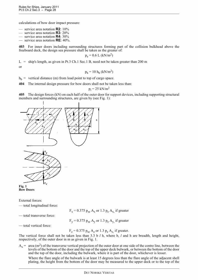
Rules for Ships, January 2011 Pt.5 Ch.2 Sec.3 – Page 28
calculations of bow door impact pressure:
— service area notation R2: 10%— service area notation R3: 20%— service area notation R4: 30%— service area notation RE: 40%.
403 For inner doors including surrounding structures forming part of the collision bulkhead above thefreeboard deck, the design sea pressure shall be taken as the greater of:
pe = 0.6 L (kN/m2)
L = ship's length, as given in Pt.3 Ch.1 Sec.1 B, need not be taken greater than 200 mor
ph = 10 hb (kN/m2)
hb = vertical distance (m) from load point to top of cargo space.404 The internal design pressure for bow doors shall not be taken less than:
pi = 25 kN/m2
405 The design forces (kN) on each half of the outer door for support devices, including supporting structuralmembers and surrounding structures, are given by (see Fig. 1):
Fig. 1Bow Doors
External forces:— total longitudinal force:
Fx = 0.375 pse Ax or 1.3 pe Ax, if greater— total transverse force:
Fy = 0.375 pse Ay or 1.3 pe Ay, if greater— total vertical force:
Fz = 0.375 pse Az or 1.3 pe Az, if greater.The vertical force shall not be taken less than 3.3 b l h, where b, l and h are breadth, length and height,respectively, of the outer door in m as given in Fig. 1.
Ax = area (m2) of the transverse vertical projection of the outer door at one side of the centre line, between thelevels of the bottom of the door and the top of the upper deck bulwark, or between the bottom of the doorand the top of the door, including the bulwark, where it is part of the door, whichever is lesser.Where the flare angle of the bulwark is at least 15 degrees less than the flare angle of the adjacent shellplating, the height from the bottom of the door may be measured to the upper deck or to the top of the
DET NORSKE VERITAS
Rules for Ships, January 2011 Pt.5 Ch.2 Sec.3 – Page 29
door, whichever is lesser.In determining the height from the bottom of the door to the upper deck or to the top of the door, thebulwark shall be excluded.
Ay = area (m2) of the longitudinal vertical projection of the outer door between the levels of the bottom of thedoor and the top of the upper deck bulwark, or between the bottom of the door and the top of the door,including the bulwark, where it is part of the door, whichever is lesser.Where the flare angle of the bulwark is at least 15 degrees less than the flare angle of the adjacent shellplating, the height from the bottom of the door may be measured to the upper deck or to the top of thedoor, whichever is lesser.
Az = area (m2) of the horizontal projection of the outer door at one side of the centre line, between the bottomof the door and the top of the upper deck bulwark, or between the bottom of the door and the top of thedoor, including the bulwark, where it is part of the door, whichever is lesser.Where the flare angle of the bulwark is at least 15 degrees less than the flare angle of the adjacent shellplating, the height from the bottom of the door may be measured to the upper deck or to the top of thedoor, whichever is lesser.
The design pressures shall be calculated at the position h/2 above the bottom of the door and l/2 aft of the stemline.For outer doors, including bulwark, of unusual form or proportions, the areas and angles used for determinationof the design values of external forces may require special consideration.Internal forces:
— total longitudinal force: Fxi = p i Ax— total transverse force: F yi = pi Ay.
406 The design force (kN) on the inner door for support devices, including supporting structural membersand surrounding structures, is given by:External force:— total longitudinal force:
Fx = pe Ax or ph Ax, if greater.Internal force:— total longitudinal force:
Fxi = pi Ax
Ax = inner door area (m2).
D 500 Strength criteria501 In connection with direct strength calculations as stipulated in 903, scantlings of primary members andsupports of bow doors shall be determined to withstand the design pressures using the following allowablestresses:
Table D1 Allowable stresses, outer doorsDesign
pressure
p (N/mm2)
Shear stress
t (N/mm2)
Bending or normal stress
σ (N/mm2)
Equivalent stress
σe (N/mm2)
pe or pi 80 f1 120 f1 150 f10.375 pse 105 f1 160 f1 200 f1
Table D2 Allowable stresses, inner doorsDesign
pressure
p (N/mm2)
Shear stress
t (N/mm2)
Bending or normal stress
σ (N/mm2)
Equivalent stress
σe (N/mm2)p e, ph or pi 105 f1 160 f1 200 f1
DET NORSKE VERITAS

Rules for Ships, January 2011 Pt.5 Ch.2 Sec.3 – Page 30
502 Allowable stresses in support devices and supporting members and surrounding structure:
503 The nominal tension in way of threads of bolts not carrying support forces shall not exceed 125f1 (N/mm2).504 Nominal bearing pressure, determined by dividing the design force by the projected bearing area, shallnot exceed 0.8 σF (N/mm2) for steel material where σF is the yield stress for the bearing material. For otherbearing materials the nominal bearing pressure will be specially considered.
D 600 Structural arrangement601 Bow doors shall be adequately stiffened, and means shall be provided to prevent lateral or verticalmovement of the doors when closed. For outer doors of the visor type adequate strength shall be provided inthe connections of lifting arms to the door and the ship structure.602 For outer doors the structural arrangement and the member scantlings shall comply with the requirementsfor bow impact in Pt.3 Ch.1 Sec.7 E and associated requirements given under D700 - D900.
D 700 Plating701 The thickness requirement of the bow door plating corresponding to lateral pressure is given by thegreater of:
— inner and outer doors:
(for calculation of t1 for inner doors, pe to be taken as the greatest of pe, ph or pi)— outer doors:
psl = as given in Pt.3 Ch.1 Sec.7 E.ka = correction factor for aspect ratio of plate field
= (1.1 – 0.25 s/l)2= maximum 1.0 for s/l = 0.4= minimum 0.72 for s/l = 1.0
The thickness of the inner door shall not be less than the minimum thickness for the collision bulkhead as givenin Pt.3 Ch.1 Sec.9 C.
D 800 Stiffeners801 The elastic/plastic section modulus of horizontal or vertical stiffeners shall not be less than the greater of:
— inner and outer doors. The elastic section modulus, Z1 shall not be less than:
(for calculation of Z1 for inner doors, pe to be taken as the greatest of pe, ph or pi)
— outer doors:
Table D3 Allowable stresses, outer doorsDesign
pressure
p (N/mm2)
Shear stress
t (N/mm2)
Bending or normal stress
σ (N/mm2)
Equivalent stress
σe (N/mm2)0.375 pse, 1.3
peor 1.3pi
105 f1 160 f1 200 f1
Table D4 Allowable stresses, inner doorsDesign
pressure
p (N/mm2)
Shear stress
t (N/mm2)
Bending or normal stress
σ (N/mm2)
Equivalent stress
σe (N/mm2)p e, ph or pi 105 f1 160 f1 200 f1
t11.58kas pe
f1----------------------------- mm( )=
t213.8kas psl
σf------------------------------ mm( )=
Z10.8 l2s pe
f1----------------------- (cm3 )=
DET NORSKE VERITAS
Rules for Ships, January 2011 Pt.5 Ch.2 Sec.3 – Page 31
The plastic section modulus of shell stiffeners, ZP, as defined in Pt.3 Ch.1 Sec.3 C shall not be less than as givenin Pt.3 Ch.1 Sec.7 E with tk = 0.802 The stiffener web plate at the ends shall have a net sectional area not less than the greater of:
— inner and outer doors:
(for calculation of A1 for inner doors, pe to be taken as the greatest of pe, ph or pi)
— outer doors:
A2 = AS as given for shell stiffeners in Pt.3 Ch.1 Sec.7 E with tk = 0.
D 900 Girders901 The section modulus of single girders shall not be less than the greater of:
— outer doors:
— inner doors (pe to be taken as the greatest of pe, ph or pi)
— outer doors:
Z2 = Z, as given in Pt.3 Ch.1 Sec.7 E with wk = 1.0 for primary members supporting shell stiffeners.
902 The web area requirement (after deduction of cut-outs) at the girder ends is given by the greater of:
— inner and outer doors:
(for calculation of A1 for inner doors, pe to be taken as the greatest of pe, ph or pi)
— outer doors:
A2 = A as given in Pt.3 Ch.1 Sec.7 E with tk = 1.0 for primary members supporting shell stiffeners.
903 For large doors with a complex girder system a direct stress analysis of the door structure includingsupports may be required. Allowable stresses are given in 501 and 502.904 The buckling strength of primary members shall be verified as being adequate.905 The arrangement, scantlings and stiffening of girders and diaphragms supporting shell frames of outer bowdoors shall comply with requirements given in Pt.3 Ch.1 Sec.7 E.906 The girder system shall be given sufficient stiffness to ensure integrity of the boundary support of thedoor. The stiffness of the edge girders shall be related to the distance between supports and to the loads fromthe main door girders.907 Where inner doors serve as vehicle ramps wheel loads shall be considered as given in B300.
D 1000 Closing arrangement, general1001 Adequate provisions shall be arranged for closing of bow doors so as to be commensurate with thestrength and stiffness of the surrounding structure.1002 Devices provided for closing of bow doors shall be simple to operate and easily accessible.1003 Closing arrangement for bow doors shall be provided with devices arranged for remote control from aconvenient position above the freeboard deck. The operating panel for remotely controlled bow doors shall beinaccessible for unauthorised persons.1004 Notice plates, giving instructions that bow doors shall be closed and all devices provided for closing areclosed and locked before leaving quay-side (or terminal) shall be placed at the operating panel and on the
A10.08l s pe
f1------------------------- (cm2 )=
Z11.05 S2 b pe
f1------------------------------ (cm3 )=
Z10.8 S2 b pe
f1--------------------------- (cm3 )=
A10.08 S b pe
f1--------------------------- (cm2 )=
DET NORSKE VERITAS
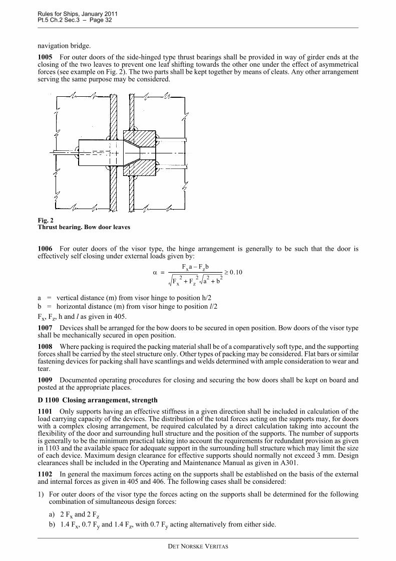
Rules for Ships, January 2011 Pt.5 Ch.2 Sec.3 – Page 32
navigation bridge.1005 For outer doors of the side-hinged type thrust bearings shall be provided in way of girder ends at theclosing of the two leaves to prevent one leaf shifting towards the other one under the effect of asymmetricalforces (see example on Fig. 2). The two parts shall be kept together by means of cleats. Any other arrangementserving the same purpose may be considered.
Fig. 2Thrust bearing. Bow door leaves
1006 For outer doors of the visor type, the hinge arrangement is generally to be such that the door iseffectively self closing under external loads given by:
a = vertical distance (m) from visor hinge to position h/2b = horizontal distance (m) from visor hinge to position l/2Fx, Fz, h and l as given in 405.1007 Devices shall be arranged for the bow doors to be secured in open position. Bow doors of the visor typeshall be mechanically secured in open position.1008 Where packing is required the packing material shall be of a comparatively soft type, and the supportingforces shall be carried by the steel structure only. Other types of packing may be considered. Flat bars or similarfastening devices for packing shall have scantlings and welds determined with ample consideration to wear andtear.1009 Documented operating procedures for closing and securing the bow doors shall be kept on board andposted at the appropriate places.
D 1100 Closing arrangement, strength1101 Only supports having an effective stiffness in a given direction shall be included in calculation of theload carrying capacity of the devices. The distribution of the total forces acting on the supports may, for doorswith a complex closing arrangement, be required calculated by a direct calculation taking into account theflexibility of the door and surrounding hull structure and the position of the supports. The number of supportsis generally to be the minimum practical taking into account the requirements for redundant provision as givenin 1103 and the available space for adequate support in the surrounding hull structure which may limit the sizeof each device. Maximum design clearance for effective supports should normally not exceed 3 mm. Designclearances shall be included in the Operating and Maintenance Manual as given in A301.1102 In general the maximum forces acting on the supports shall be established on the basis of the externaland internal forces as given in 405 and 406. The following cases shall be considered:
1) For outer doors of the visor type the forces acting on the supports shall be determined for the followingcombination of simultaneous design forces:
a) 2 Fx and 2 Fzb) 1.4 Fx, 0.7 Fy and 1.4 Fz, with 0.7 Fy acting alternatively from either side.
αFxa Fzb–
Fx2 Fz
2+ a2 b2
+
------------------------------------------------- 0.10≥=
DET NORSKE VERITAS

Rules for Ships, January 2011 Pt.5 Ch.2 Sec.3 – Page 33
2) For outer doors of the side hinged type the forces acting on the supports shall be determined for thefollowing combination of simultaneous design forces:
a) Fx, Fy and Fz, with each force acting on both doorsb) 0.7 Fx, 0.7 Fy and 0.7 Fz, acting on each door separately.
Guidance note:The support forces as determined according to 1 a) and 2 a) shall in general give rise to a zero moment in thelongitudinal vertical plane about the transverse axis at h/2 and l/2.
---e-n-d---of---G-u-i-d-a-n-c-e---n-o-t-e---
1103 For outer doors effective supports including surrounding door and hull structural members are, in thecase of failure of any single support, to have sufficient capacity to withstand the total design forces. In this casethe allowable stresses given in Table D3 in 502 may be increased by 20%.1104 For outer doors of the visor type, at least two securing devices shall be provided at the bottom of thedoor, each capable of providing the full reaction force required to prevent opening of the door within theallowable stresses given in Table D3. The opening moment to be balanced by the said reaction force shall notbe taken less than:
M0 = 1.3 (10 W d + 5 Ax a) (kNm)
W = mass of the door (t)a = vertical distance (m) from visor hinge to the centroid of the vertical projected area of the bow visord = vertical distance (m) from hinge axis to the centre of gravity of the door.Ax as defined in 405.1105 All load transmitting elements in the design load path, from the door through supports into the shipstructure, including welded connections, shall be to the same strength standard as required for the supports.1106 The lifting arms of a visor type outer door and its connections to the door and hull structure shall bedimensioned for the static and dynamic forces applied during lifting and lowering operations. A minimum windpressure of 0.0015 N/mm2 shall be taken into account.
D 1200 Closing arrangement, system for operation and indication and monitoring1201 Cleats and support devices shall be equipped with locking arrangement (self locking or separatearrangement) or shall be of the gravity type.
Guidance note:Alternative locking arrangements may be accepted depending upon the location and reliability of the arrangement.
---e-n-d---of---G-u-i-d-a-n-c-e---n-o-t-e---
1202 Where hydraulic operating systems are applied, cleats and support devices shall remain locked in theclosed position in case of failure in the hydraulic system.1203 Systems for operation of cleats and support devices and, where applicable, for locking arrangementshall be interlocked in such a way that they can only operate in the proper sequence. Hydraulic operatingsystems shall be isolated from other circuits and shall be inhibited when doors and closing arrangement are inthe closed or locked position.1204 Indication of the open or closed position of any of the bow doors and indication that cleats, support andlocking devices, as applicable, are properly positioned shall be provided at the operating panel for remotecontrol. The indication panel shall be provided with a lamp test function.When a mechanical lock is placed inside the hydraulic cylinder operating a cleat or support, indication of theopen or closed position of the cleat or support shall be made on the lock inside the cylinder.1205 Separate indicator lights and audible alarms shall be provided on the navigation bridge to show andmonitor that each of the bow doors is properly closed and that cleats, support and locking devices as applicableare properly positioned.The indicator system shall show by visual indication if any of the bow doors are not fully closed and not fullylocked, and by audible alarms if securing devices become open or locking devices become unsecured.
DET NORSKE VERITAS
Rules for Ships, January 2011 Pt.5 Ch.2 Sec.3 – Page 34
1206 The alarm and indication panel on the navigation bridge shall be equipped with a mode selectionfunction “harbour/sea voyage” so arranged that audible alarm is given on the navigation bridge if the vesseldeparts the quay side (or terminal) with any of the bow doors not properly closed or any of the cleats, supportand locking devices not properly positioned.1207 The indicator and alarm systems on the navigation bridge mentioned under D1200 shall be designed onthe fail-to-safe principle in compliance with the following:
1) The indication panel shall be provided with:
— a power failure alarm, provided for both power sources
— an earth failure alarm— a lamp test device— for each door, separate indications for door closed / not closed, door locked/not locked.— a dimmer (however, it shall not be possible to turn off the indicator lights completely).
2) The electrical circuits used for indicating door position shall be normally closed when the door is completelyclosed and completely open. When more limit switches are provided for each door they may be connectedin series.
3) The electrical circuit used for indicating securing arrangements position shall be normally closed when thesecuring arrangements are completely locked and completely un-locked. When more limit switches areprovided for each door they may be connected in series.
4) Separate circuits shall be arranged for indication of door position (closed/not closed) and for securingarrangements position (locked/not locked). Multicore cable is permitted.
5) In case of dislocation of limit switches, this shall be indicated by not closed/not locked/securingarrangement not in place - as appropriate.
1208 The power supply for indicator and alarm systems for operating and closing doors shall be independentof the power supply for the operating and closing arrangements and shall be provided with a backup powersupply from the emergency source of power or other secure power supply, e.g. UPS (Uninterrupted PowerSupply) with a minimum capacity of 30 minutes.1209 Sensors for the indicator system shall be protected from water, ice formation and mechanical damage.1210 A water leakage detection system with audible alarm and television surveillance shall be arranged toprovide an indication to the navigation bridge and to the engine control room of leakage through the inner door.1211 In the space between the outer and the inner doors a television surveillance system shall be arrangedwith monitors on the navigation bridge and in the engine control room. The system shall monitor the positionof the doors and a sufficient number of devices for the closing arrangement. Special consideration shall begiven for the lighting and contrasting colour of objects under surveillance.1212 A drainage system shall be arranged in the space between the bow door and ramp, or where no ramp isfitted, between the bow door and inner door. The system shall be equipped with an audible alarm function tothe navigation bridge being set off when the water levels in these areas exceed 0.5 m or the high water levelalarm, whichever is lesser.1213 Special category spaces and ro-ro spaces shall be continuously patrolled or monitored by effectivemeans, such as television surveillance, so that any movement of vehicles in adverse weather conditions andunauthorised access by passengers thereto can be detected whilst the ship is underway.
Guidance note:Items 1204 to 1212 apply to shell doors, loading doors and other closing appliances for all passenger ships with ro-rospaces or special category spaces as defined in A400 which, if left open or not properly closed and locked, could leadto a major flooding of such spaces.
---e-n-d---of---G-u-i-d-a-n-c-e---n-o-t-e---
E. Inlets and Drainage Arrangement
E 100 Air intakes, ventilators, etc.101 Location of air intakes for engines will be considered in each case.102 In ships with the class notation A the following apply:
a) If air intakes for engines are led through superstructure sides, the distance from the lower side of theopening to the freeboard deck shall not be less than 4.5 m, and a drainage box shall be fitted between the
DET NORSKE VERITAS
Rules for Ships, January 2011 Pt.5 Ch.2 Sec.3 – Page 35
ship's side and the engine room, draining directly overboard.b) If ventilators, etc. without weathertight closing appliances are led through superstructure sides, the distance
from the lower side of the ventilator opening to the freeboard deck shall not be less than 4.5 m.
E 200 Drainage of vehicle deck (class notation A)201 In addition to the requirements in 202 and 203, drainage of vehicle decks within superstructures shallcomply with the requirements given in Pt.4 Ch.6.202 If the drainage openings in the vehicle deck will be lower than the waterline when the ship loaded tosummer freeboard has a list of 5°, the outlets shall be led down to a separate tank.203 Each scupper shall have an automatic non-return valve with a positive means of closing it from a positionabove the freeboard deck. Where, however, the vertical distance from the summer load waterline to the inboardend of the discharge pipe exceeds 0.01 L, the discharge may have two automatic non-return valves withoutpositive means of closing, provided that the inboard valve is always accessible for examination under serviceconditions. The means for operating the positive action valve shall be readily accessible and provided with anindicator showing whether the valve is open or closed.
E 300 Freeing ports (class notation B)301 The vehicle deck freeing port area shall not be less than required for an open freeboard deck accordingto Pt.3 Ch.3 Sec.6 M.
F. StabilityF 100 General101 Ships with class notation Car Ferry, Train Ferry or Car and Train Ferry shall comply with therequirements of Pt.3 Ch.3 Sec.9 as well as the requirements of Sec.2 F for Passenger Ships.
Guidance note:For vessels arranged with a lower ro-ro cargo hold below the bulkhead deck Regulation 4, 5, 6 and 7 of SOLAS 74,Ch. II-1, Part B are not considered applicable. For such ferries two alternatives are considered applicable:Compliance with IMO Res. A.265(VIII) when applied in it's entirety. The inboard penetration of SOLAS damages in way of the lower ro-ro cargo hold, including damages involving theboundary bulkheads, are extended to the centreline. The lower ro-ro cargo hold should be assumed to have a permeabilityequal to 0.90 unless a lesser value can be demonstrated by calculation. For this damage conditions the vessel should meetthe criteria according to SOLAS 74, Ch. II-1, Part B, Reg. 8.2.3. It is recommended that a double bottom in way of thelower cargo hold has a value of at least B/10.
---e-n-d---of---G-u-i-d-a-n-c-e---n-o-t-e---
102 For ships in domestic trade and with service restrictions, alternative stability requirements may beaccepted after considerations in each separate case.
G. Life Saving Appliances and ArrangementsG 100 Application101 Ships with class notation Car Ferry, Train Ferry or Car and Train Ferry shall comply with therequirements of subsection F.
G 200 Additional requirements for ro-ro passenger ships (Regulation III/26)
1 This regulation applies to all ro-ro passenger ships. Ro-ro passenger ships constructed:1.1 on or after 1 July 1998 shall comply with the requirements of paragraphs 2.3, 2.4, 3.1, 3.2, 3.3, 4 and 5.
2 Liferafts2.3 Every liferaft on ro-ro passenger ships shall be of a type fitted with a boarding ramp complying with the
requirements of paragraph 4.2.4.1 or 4.3.4.1 of the Code, as appropriate.
DET NORSKE VERITAS

Rules for Ships, January 2011 Pt.5 Ch.2 Sec.3 – Page 36
2.4 Every liferaft on ro-ro passenger ships shall either be automatically self-righting or be a canopied reversible liferaft which is stable in a seaway and is capable of operating safely whichever way up it is floating. Alternatively, the ship shall carry automatically self-righting liferafts or canopied reversible liferafts, in addition to its normal complement of liferafts, of such aggregate capacity as will accommodate at least 50% of the persons not accommodated in lifeboats. This additional liferaft capacity shall be determined on the basis of the difference between the total number of persons on board and the number of persons accommodated in lifeboats. Every such liferaft shall be approved by the Administration having regard to the recommendations adopted by the Organization.*
3 Fast rescue boats3.1 At least one of the rescue boats on a ro-ro passenger ship shall be a fast rescue boat approved by the
Administration having regard to the recommendations adopted by the Organization.* *3.2 Each fast rescue boat shall be served by a suitable launching appliance approved by the Administration.
When approving such launching appliances, the Administration shall take into account that the fast rescue boat is intended to be launched and retrieved even under severe adverse weather conditions, and also shall have regard to the recommendations adopted by the Organization.* *
3.3 At least two crews of each fast rescue boat shall be trained and drilled regularly having regard to the Seafarers Training, Certification and Watchkeeping (STCW) Code and recommendations adopted by the Organization,*** including all aspects of rescue, handling, manoeuvring, operating these craft in various conditions, and righting them after capsize.
4 Means of rescue4.1 Each ro-ro passenger ship shall be equipped with efficient means for rapidly recovering survivors from the
water and transferring survivors from rescue units or survival craft to the ship.4.2 The means of transfer of survivors to the ship may be part of a marine evacuation system, or may be part
of a system designed for rescue purposes.4.3 4.3 If the slide of a marine evacuation system is intended to provide the means of transfer of survivors to
the deck of the ship, the slide shall be equipped with handlines or ladders to aid in climbing up the slide.5 Lifejackets
5.1 Notwithstanding the requirements of regulations 7.2 and 22.2, a sufficient number of life jackets shall be stowed in the vicinity of the muster stations so that passengers do not have to return to their cabins to collect their life jackets.
5.2 In ro-ro passenger ships, each lifejacket shall be fitted with a light complying with the requirements of paragraph 2.2.3 of the Code.
* Refer to the requirements for automatically self-righting liferafts and canopied reversible liferafts, MSC/Circ.809.** Refer to recommendations to be adopted by the Organization.*** Refer to the Recommendation on training requirements for crews of fast rescue boats, adopted by the Organization
by resolution A.771(18) and section A-VI/2, table A-VI/2-2 “Specification of the minimum standard of competence in fast rescue boats” of the Seafarers' Training, Certification and Watchkeeping (STCW) Code.(SOLAS Reg. III/26)
DET NORSKE VERITAS

Rules for Ships, January 2011 Pt.5 Ch.2 Sec.4 – Page 37
SECTION 4 GENERAL CARGO CARRIERS
A. GeneralA 100 Classification101 The requirements in this section apply to ships intended for carriage of general dry cargoes.102 Ships arranged for general cargo handling and built in compliance with relevant requirements specifiedin the following may be given the class notation General Cargo Carrier.103 Ships arranged for roll on/roll off cargo handling and built in compliance with relevant requirementsspecified in the following may be given the class notation General Cargo Carrier RO/RO.104 Ships arranged for general cargo handling and where the decks and inner bottom are built in compliancewith relevant requirements in C, will be given the additional class notation PWDK.105 Ships arranged for general cargo handling and also arranged for carriage of vehicles with fuel in theirtanks shall comply with requirements given in SOLAS Reg. II-2/20, and will, when in compliance, be giventhe class notation PET. For further information regarding SOLAS requirements, reference is made to Pt.4Ch.10 Sec.4.106 Ships arranged for roll on/roll off cargo handling (class notation General Cargo Carrier RO/RO)shall have decks, inner bottom, ramps and lifts fulfilling the strength requirement in C. Additionally, therequirements for class notation PET (see 105) shall be complied with. 107 Ships intended for carriage of dry bulk and built in compliance with the requirements given in Sec.5 willbe given the class notation General Cargo Carrier HC-A (or HC-B, HC-C, HC-B*, HC-M). The bulkcarrier notations BC-A, BC-B, BC-C or BC-B* may also be applied on a voluntary basis.The notations HC-A, HC-B, HC-C, HC-B* or HC-M may be omitted for vessels of special arrangement uponspecial consideration.
A 200 Documentation201 For the approval of deck structure of General Cargo Carrier, the following plans shall be submitted:
— type of cargo handling vehicles including maximum axle load and details of wheel and/or foot printarrangement
— uniform deck load— plans according to 203, when relevant.
202 For the approval of structures subjected to wheel loading (PWDK) the following information shall besubmitted:
— type of cargo handling vehicles including maximum axle load and details of wheel and/or foot printarrangement
— maximum axle load and axle arrangement for all vehicles (cars, trucks, dumpers, road trailers, MAFItrailers, busses, etc.) shall be carried onboard. Details of wheel and/or foot print should be included.
— uniform deck load— stowage and securing arrangement for all vehicles to be carried. Stowage plan shall include the most
unfavourable combination of vehicles that may be positioned on deck— plans for supporting structure for lashing points, if relevant.
203 For approval of internal ramps and ramps for shore connections, the following information shall besubmitted:
— maximum number of vehicles with and or the most unfavourable combination of vehicles which may besituated on the ramp
— maximum lifting force and hinge forces, including force direction— hoisting and securing arrangement in working and stowed position— tightening arrangement against water penetration, if relevant— proposed procedure for functional testing— plans and supplementary documentation giving pertinent particulars of the hoisting/lowering mechanical
gear arrangement— schematic diagrams of hydraulic systems, electrical systems and pneumatic systems— braking systems— plans showing scantling and layout of supporting structure for hinges, release hook, cleatings, operating
winches, king post and other relevant RO/RO equipment.
DET NORSKE VERITAS
Rules for Ships, January 2011 Pt.5 Ch.2 Sec.4 – Page 38
204 For the approval of securing points for road vehicles and cars, the following information shall besubmitted:
— securing points for lashing with data regarding position, type, design of fittings and Maximum SecuringLoad (MSL)
— stowage and securing arrangement for all vehicles to be carried— maximum axle load and number of axles of vehicles.
205 For ships built for carriage of vehicles with fuel in their tanks (PET) the following plans and particularsshall be submitted for approval:
— arrangement plan(s) as specified in Pt.4 Ch.8 showing all electrical equipment in spaces where vehicles arecarried, with specification of make, type and rating of all such equipment and of cable types.
— plan(s) as specified in Pt.4 Ch.10 Sec.4 Table A1 with reference to SOLAS 2000 Amend. Ch.II-2 Reg.20.
206 For ships built in compliance with the requirement for class notation (General Cargo Carrier RO/RO) the following plans and particulars shall be submitted for approval:
— plans according to 201, 202, 204, 205.
207 If water ingress detection is arranged documentation specified in Sec.5 A305 shall be submitted forapproval.
B. Hull Arrangement and Strength
B 100 General101 Where direct stress analysis is required in the following, the design loads, calculation methods andallowable stresses are in general to be as given for complex girder systems in Pt.3 Ch.1 Sec.12.102 For ships with class notation General Cargo Carrier RO/RO, a general reference is given toClassification Note 31.2 for the strength analysis of racking constraining structure, girder system and pillars. Classification Note 31.2 shows acceptable load cases, loads and relevant acceptance criteria for differentstructural elements.103 In ships with cargo hatchways the upper deck and 'tween deck(s) are normally supported by decktransverses (hatch side cantilevers) extending from a side vertical to the hatch side coaming. The scantlingsshall be dimensioned as given in B600.104 For open type ships with weather deck hatch openings in one transverse section of substantial breadthand length, the combined effects of hull girder bending and torsion related to possible local bending and shearmay have to be specially considered as outlined in Classification Note No. 31.7.105 Movable car decks, if fitted, shall satisfy relevant requirements given in Sec.7 C.106 If cargo decks are supported by pillars, the pillars shall normally extend to the bottom structure or asupporting bulkhead. Direct stress analysis of deck structure and bottom structure in way of pillars may benecessary.107 Supports for pillars shall be designed so as also to withstand tensile forces, if relevant.108 Strength of pillars shall be assessed assuming summary of maximum loads of the decks.109 Double bottom in ships with decks supported by pillars on the double bottom shall be investigated forrelevant seagoing draught including maximum ballast draught, minimum 0.6 T, with no loads on decks above.Counteracting forces due to ballast in double bottom may be taken into account in the analysis.110 Double bottoms not supported by pillars or vertical pillar bulkheads shall be investigated for relevantdraught, normally maximum draught, with no load on the inner bottom.111 Double bottom structure may have to be specially considered for the docking condition with relevantacceptance criteria according to Classification Note 31.2.112 Deck girder structure shall be checked for the uniform deck load (UDL) at relevant seagoing conditiondraught and applied as evenly and unevenly distributed on the deck. 113 The deck girder structure shall be checked for the most severe axle position for load handling vehiclesand vehicles to be carried. 114 The hull structure shall be assessed for damage condition with acceptance criteria according to Pt.3 Ch.1Sec.12.
DET NORSKE VERITAS

Rules for Ships, January 2011 Pt.5 Ch.2 Sec.4 – Page 39
115 Due attention shall be put to fatigue of structural details. For further information, references are made toB500.116 Strength of decks intended for carrying MAFI trailers or other vehicles carrying more than one tier ofcontainers, shall be specially considered in a heeled condition.
B 200 Strength analysis levels201 The hull structure for General Cargo Carrier RO/RO and Car Carrier (see Sec.7) shall be analysedaccording to Level 1 as described in Classification Note 31.2.202 The hull structure for General Cargo Carrier RO/RO and Car Carrier (see Sec.7) that are alsoanalysed according to Level 2 (Classification Note 31.2) will be given the additional class notationNAUTICUS (Newbuilding).203 The hull structure for General Cargo Carrier RO/RO and Car Carrier (Sec.7) that are also analysedaccording to Level 3 (Classification Note 31.2) will be given the additional class notation CSA-2 (see Pt.3 Ch.1Sec.15 E).
B 300 Longitudinal strength301 Longitudinal strength shall be checked for relevant loading conditions as described in Pt.3 Ch.1 Sec.5B100. Due attention should be put to the sagging and hogging bending moments for non-homogenous loadingconditions. 302 A still water sagging moment below the minimum Rule sagging moment may only be accepted providedthe strength can be documented for a non-homogenous loading with maximum realistic load concentrationwithin 0.4 L amidships.
B 400 Transverse strength401 Vessels with a limited number of effective transverse strength structures for racking (class notationGeneral Cargo Carrier RO/RO) shall be subject to a direct strength analysis to demonstrate that the stressesare acceptable in a heeled condition. Acceptable calculation methods are given in Classification Note No. 31.2. 402 For ships with limited hull depth (class notation General Cargo Carrier RO/RO), the transversestrength is usually secured by having self supporting side verticals. A simplified racking assessment usingbeam models will then be accepted for documentation of the transverse strength.
B 500 Fatigue501 Structural details of transverse racking constraining structure shall be specially considered to ensure aproper resistance against fatigue. Classification Note 31.2 describes acceptable loads and procedures for suchanalyses.502 For ships with limited hull depth (class notation General Cargo Carrier RO/RO), the side verticalsare usually designed self supporting with respect to racking. In such case, a proper fatigue life can be ensuredby controlling the general stress level in the support areas of the side verticals. Relevant loads and allowablenominal stresses are those described in Classification Note 31.2.
B 600 Hatch side cantilevers601 Hatch side cantilevers and side verticals are shown in Fig. 1.
DET NORSKE VERITAS
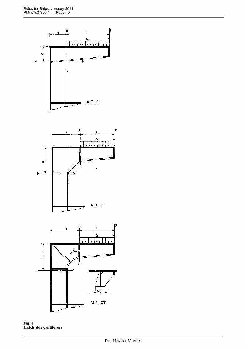
Rules for Ships, January 2011 Pt.5 Ch.2 Sec.4 – Page 40
Fig. 1Hatch side cantilevers
DET NORSKE VERITAS
Rules for Ships, January 2011 Pt.5 Ch.2 Sec.4 – Page 41
602 When the cantilever may be considered as a simple girder the section modulus in sections M-M and N-N shall not be less than:
l = as given in Fig. 1 in mP = point load in kN at side coaming (from cargo on hatch cover and transversely stiffened deck)Q = distributed load in kN (from cargo on longitudinally stiffened deck).
The design pressures from cargo loads shall be calculated as given for the main class.603 For rounded corners shown in Fig. 1 (Alt. III), the effective width of the face plate shall be taken as givenin Pt.3 Ch.1 Sec.3 C400.For corner designs according to Fig. 1 (Alt. I or Alt. II), the effective width of the face plate shall be taken equal tothe actual width.604 The total effective width of the attached area of deck and shell plating may be taken as 0.4 l. The widthis, however, not to be taken greater than the cantilever spacing or the distance g in Fig. 1.605 The net web area of the cantilever shall not be less than:
x = distance in m from end of cantileverP and Q = as given in 202.606 The thickness of the corner plate between the sections M-M and N-N shall not be less than:
The corner plate in Fig. 1 (Alt. I and Alt. II) shall be additionally stiffened if a and g is greater than 70 t.P and Q = as given in 202l, a and g = as given in Fig. 1.
B 700 External vehicle ramps701 Vehicle ramps for shore connection are normally to be built with a grillage system of girders, and localstiffeners in the vehicle's moving direction. The ramps shall have sufficient strength for the specified designworking loads and maximum loads during hoisting operation. After end ramps shall have sufficient flexibilityfor resting on the quay during loading/unloading operations with a minimum list of 3 degrees. A direct stressanalysis may have to be carried out to demonstrate that stresses and flexibility are acceptable.702 Plates and stiffeners shall satisfy the strength requirements given in C.703 If the ramp is also acting as a watertight door, relevant requirements given for the main class shall besatisfied.704 The support structure for large ramps in stowed position will have to be specially considered based ondesign loads as given for heavy units in Pt.3 Ch.1 Sec.4 C. A direct stress analysis may have to be carried out.705 Satisfactory functional tests shall be carried out.706 Control handles for winches or operation devices shall be so arranged that they quickly revert to theneutral (stop) position when released. Provision shall be made to lock handles in the neutral position when theoperating gear is unattended.
B 800 Internal ramps and lifts801 Internal ramps and lift platforms shall have sufficient strength for the specified design working load. Forhoistable ramps and lifts also the maximum loads during hoisting conditions shall be considered.802 Plates and stiffeners shall satisfy the strength requirements given in C for permanent decks for wheelloading.803 Ramps or lift platforms acting as deck opening covers shall satisfy the relevant requirements to the deckaccording to the main class.
Z 6f1---- l P 0.5Q+( ) (cm3 )=
A 0.12f1
----------- P Qxl---+⎝ ⎠
⎛ ⎞ (cm2 )=
t 0.012f1
-------------- P 0.5 Q+( ) lag------ (mm)=
DET NORSKE VERITAS
Rules for Ships, January 2011 Pt.5 Ch.2 Sec.4 – Page 42
804 Satisfactory functional tests shall be carried out.
B 900 Ceilings and cargo battens901 Ships with single bottom in cargo holds shall be fitted with ceiling on top of floors, extending to the upperpart of the bilges. Limber boards shall be arranged to provide easy access for inspection of the bottomstructures.902 Any wooden ceiling on inner bottom shall be fitted either directly in a layer of tightening and preservingcomposition or on battens of thickness at least 12.5 mm. The thickness of wooden ceiling shall not be less than63 mm. In way of the bilges removable ceiling shall be fitted. Deck composition as mentioned in 304 insteadof wooden ceiling shall be satisfactory strengthened. There shall be effective drain to the bilges.903 In spaces for general dry cargo, battens are normally to be fitted on ship's sides from upper turn of bilge(or from deck in between deck spaces and superstructures) up to the under side of beam knees. The clear spacebetween adjacent rows of battens shall not exceed 300 mm. The thickness of wooden battens shall not be lessthan 50 mm.904 Deck compositions are subject to approval by the Society. See “Register of Type Approved ProductsNo.3: Containers, Cargo Handling, Lifting Appliances and Miscellaneous Equipment”.
B 1000 Protection of cargo1001 It is assumed that adequate precautions are taken when necessary to prevent hazards from cargoeswhich are subject to gassing, oxidation, self-heating or spontaneous combustion in connection with heating,moisture or other detrimental affecting of the cargo. The above mentioned assumption will be stated in theappendix to the classification certificate for the ship.
B 1100 Support of cargo handling equipment1101 Masts and posts shall be efficiently supported and connected to at least two decks or to one deck and amast house top above. If the latter arrangement is adopted, the mast house top shall be of sufficient size andadequately stiffened. A winch house of usual size and scantlings is not considered to meet the requirements.1102 At fastenings for standing rigging and for guys and topping lifts, the deck shall be securely stiffenedand reinforced for the additional loading.1103 The support of other lifting arrangement will be specially considered.
B 1200 Securing points for lashing1201 Decks intended for carriage of vehicles shall be equipped with a satisfactory number of securing points(cargo securing device) for lashing of the vehicles. The arrangement of securing is left to the discretion of theowner, provided the minimum requirements in 1202 through 1208 are satisfied.1202 Unless otherwise specified, each lashing point shall have a Maximum Securing Load (MSL) of not lessthan:
MSL= k Q g0, min. 100 kN in decks for road vehiclesmin. 15 kN in decks for cars only
k = n/rr = number of effective lashing points at each side of the vehicle for the number n of axles in group.
If r is different from 1, k to be increased by 10%.Q = the maximum axle load given in tons. For MAFI road trailers, Q can be calculated as the total weight with n = 1 and r = the total number of lashingsat each side. 1203 Maximum securing loads in securing points shall not exceed:MSL = 0.5 Pm
Pm = minimum breaking load of the considered cargo securing device.1204 If the securing point is designed to accommodate more than one lashing, the magnitude and directionof the lashing loads shall be taken into account when determining the total MSL of the securing point.1205 Lashing points intended for a maximum working load of 15 kN can normally be arranged without anystrengthening of the deck plating.1206 Lashing points intended for a maximum working load of more than 15 kN shall have documented itsstrength in terms of structural analysis or mock-up tests.
DET NORSKE VERITAS
Rules for Ships, January 2011 Pt.5 Ch.2 Sec.4 – Page 43
1207 Fixed cargo securing devices shall be certified by DNV, according to the requirements given in Sec.6D and E.Portable cargo securing devices shall be of a certified type. If the securing devices shall be certified by DNV,the requirements are as given in Sec.6 D and E.
1208 Nominal normal and shear stresses in local structures of hull structural steel, supporting sockets forlashing shall not exceed:
σ = 210 f1 N/mm2
τ = 120 f1 N/mm2
In structures also subjected to longitudinal stresses (e.g. deck longitudinals and girders) in combination withsuch stresses as given in Pt.3 Ch.1 Sec.8, the allowable bending stresses in Pt.3 Ch.1 Sec.8 Table C1 and D201shall be increased by 30%.
B 1300 Steel coils
1301 For vessels intended to carry steel coils, the inner bottom plating and inner bottom longitudinals will beespecially considered.
1302 An acceptable calculation method is given in Classification Note No. 31.1.
C. Permanent Decks for Wheel Loading
C 100 General
101 Ships strengthened in accordance with the following requirements may have the additional class notationPWDK.
102 The requirements cover wheel loads from cargo handling vehicles and from cargo transporting vehicleskept onboard and supported on their wheels when the ship is at sea. Vehicles supported by crutches, horses etc.will be specially considered.
103 Scantling for stiffeners of decks intended for carrying MAFI trailers or other vehicles carrying more thanone tier of container, shall be specially considered in a heeled condition.
104 The strength requirements are based on the assumption that the considered element (plating or stiffener)is subjected to one load area only, and that the element is continuous in both directions across several evenlyspaced supports. Requirements for other loads and or boundary conditions will be specially considered.
105 Signboards stating the maximum permissible axle load, the maximum tyre pressure of pneumatic tyrewheels, wheel arrangement on axles, and specially approved vehicles shall be fitted in suitable positionsonboard. Detailed information of the basis for approval will be stated in the appendix to the classificationcertificate.
106 Other types and combinations of car decks and materials may be approved after special considerations inthe individual case.
C 200 Design loads
201 For individual vehicles with specified arrangement and dimensions of footprints, the design pressure isin general to be taken as:
Q = maximum axle load in tno = number of loads areas on the axlea = extent in m of the load area parallel to the stiffeners (See Fig. 2)b = extent in m of the load area perpendicular to the stiffeners (see Fig. 2)av = for moving cargo handling vehicles, harbour conditions.
= vertical acceleration as defined in Pt.3 Ch.1 Sec.4 for stowed vehicles, sea going conditions
The load area as indicated in Fig. 2 are defined as:
— the footprint area of individual wheels or— the rectangular enveloped area of footprints of a wheel group.
p Qnoab------------ 9.81 0.5av+( ) (kN/m2 )=
6/ Q
DET NORSKE VERITAS
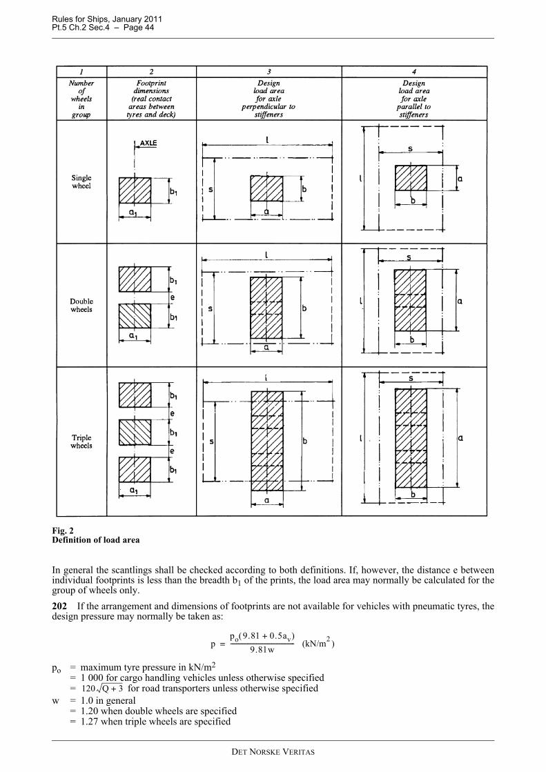
Rules for Ships, January 2011 Pt.5 Ch.2 Sec.4 – Page 44
Fig. 2Definition of load area
In general the scantlings shall be checked according to both definitions. If, however, the distance e betweenindividual footprints is less than the breadth b1 of the prints, the load area may normally be calculated for thegroup of wheels only.202 If the arrangement and dimensions of footprints are not available for vehicles with pneumatic tyres, thedesign pressure may normally be taken as:
po = maximum tyre pressure in kN/m2
= 1 000 for cargo handling vehicles unless otherwise specified= for road transporters unless otherwise specified
w = 1.0 in general= 1.20 when double wheels are specified= 1.27 when triple wheels are specified
ppo 9.81 0.5av+( )
9.81w------------------------------------------ (kN/m2 )=
120 Q 3+
DET NORSKE VERITAS
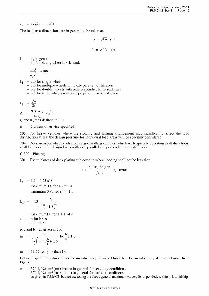
Rules for Ships, January 2011 Pt.5 Ch.2 Sec.4 – Page 45
av = as given in 201.
The load area dimensions are in general to be taken as:
k = k1 in general= k2 for plating when k2 < k1 and:
k1 = 2.0 for single wheel= 2.0 for multiple wheels with axle parallel to stiffeners= 0.8 for double wheels with axle perpendicular to stiffeners= 0.5 for triple wheels with axle perpendicular to stiffeners
k2 =
A =
Q and no = as defined in 201
no = 2 unless otherwise specified.
203 For heavy vehicles where the stowing and lashing arrangement may significantly affect the loaddistribution at sea, the design pressure for individual load areas will be specially considered.204 Deck areas for wheel loads from cargo handling vehicles, which are frequently operating in all directions,shall be checked for design loads with axle parallel and perpendicular to stiffeners.
C 300 Plating301 The thickness of deck plating subjected to wheel loading shall not be less than:
ka = 1.1 – 0.25 s/ lmaximum 1.0 for s/ l = 0.4 minimum 0.85 for s/ l = 1.0
kw =
maximum1.0 for a ≥ 1.94 sc = b for b < s
= s for b > s
p, a and b = as given in 200
m =
m = 13.57 for > than 1.0.
Between specified values of b/s the m-value may be varied linearly. The m-value may also be obtained fromFig. 3.
σ = 320 f1 N/mm2 (maximum) in general for seagoing conditions.= 370 f1 N/mm2 (maximum) in general for harbour conditions.= as given in Table C1, but not exceeding the above general maximum values, for upper deck within 0. L amidships
a kA (m)=
b A/k (m)=
wQ
nos2---------- ~100>
A2s--------
9.81wQnopo
-------------------- (m2 )
t77.4ka kwcsp
mσ------------------------------------- tk (mm)+=
1.3 4.2as-- 1.8+⎝ ⎠
⎛ ⎞ 2-------------------------–
38bs---⎝ ⎠
⎛ ⎞ 24.7b
s--- 6 5,+–
-------------------------------------------- for bs--- 1.0≤
bs---
DET NORSKE VERITAS
Rules for Ships, January 2011 Pt.5 Ch.2 Sec.4 – Page 46
For upper deck between 0.4 L amidships and 0.1 L from the perpendiculars, σ shall be varied linearly.For 'tweendecks σ shall be found by linear interpolation between upper deck value and general maximum valuetaken at the neutral axis.
Fig. 3Bending moment factor (m-values)
not greater than 1.0 for plating
for stiffeners.302 In Fig. 4 a — d the general thickness requirements of deck plating subjected to various wheel loadingfrom pneumatic tyres are given. The following parameter values have been assumed:
— tyre pressure: po = 800 kN/m2
— aspect ratio of plate field: l /s ≥ 2.5— allowable stress: σ = 370 N/mm2
— corrosion addition: tk = 0 mm.
303 The minimum deck plate thickness in dry cargo spaces can be taken as 5.0 mm for vessels with morethan two continuous decks above 0.7 D from the base line and provided the deck is kept coated and free fromcorrosion. (See also Pt.3 Ch.1 Sec.8 C104.)
C 400 Stiffeners401 The section modulus for deck beams and longitudinals subjected to wheel loading shall not be less than:
kz = 1.0 for b/s < 0.6 and b/s > 3.4
=
=
Table C1 Allowable bending stress for upper deck plating within 0.4 L amidshipsArrangement Condition σ in N/mm2
Longitudinally stiffened Seagoing 280 f1 + 60 (f1 − f2)Longitudinally stiffened Harbour 355 f1 + 20 (f1 − f2)
Transversely stiffened
Seagoing 185 f1 + 135 (f1 − f2)
Transversely stiffened
Harbour 285 f1 + 85 (f1 − f2)
x bs---=
x al--=
Z1000 kz l c d p wk
mσ------------------------------------------- (cm3 )=
1.15 0.25bs---–⎝ ⎠
⎛ ⎞ for 0.6 b/s 1.0<<
1.15 0.25bs---–⎝ ⎠
⎛ ⎞ bs--- for 1.0 b/s 3.4<<
DET NORSKE VERITAS
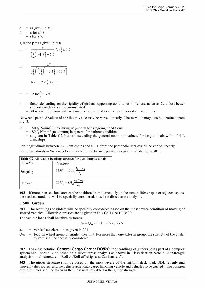
Rules for Ships, January 2011 Pt.5 Ch.2 Sec.4 – Page 47
c = as given in 301.d = a for a <l
= l for a >l
a, b and p = as given in 200
m =
m =
m =
r = factor depending on the rigidity of girders supporting continuous stiffeners, taken as 29 unless bettersupport conditions are demonstrated
= 38 when continuous stiffener may be considered as rigidly supported at each girder.
Between specified values of a/ l the m-value may be varied linearly. The m-value may also be obtained fromFig. 3.
σ = 160 f1 N/mm2 (maximum) in general for seagoing conditions= 180 f1 N/mm2 (maximum) in general for harbour conditions= as given in Table C2, but not exceeding the general maximum values, for longitudinals within 0.4 L
amidships.
For longitudinals between 0.4 L amidships and 0.1 L from the perpendiculars σ shall be varied linearly.For longitudinals in 'tweendecks σ may be found by interpolation as given for plating in 301.
402 If more than one load area can be positioned simultaneously on the same stiffener span or adjacent spans,the sections modulus will be specially considered, based on direct stress analysis.
C 500 Girders501 The scantlings of girders will be specially considered based on the most severe condition of moving orstowed vehicles. Allowable stresses are as given in Pt.3 Ch.1 Sec.12 B400.The vehicle loads shall be taken as forces
PV = QW (9.81 + 0.5 av) (kN)
av = vertical acceleration as given in 201QW = load on wheel group or single wheel in t. For more than one axles in group, the strength of the girder
system shall be specially considered.
502 For class notation General Cargo Carrier RO/RO, the scantlings of girders being part of a complexsystem shall normally be based on a direct stress analysis as shown in Classification Note 31.2 “Strengthanalysis of hull structure in Roll on/Roll off ships and Car Carriers”.503 The girder structure shall be based on the most severe of the uniform deck load, UDL (evenly andunevenly distributed) and the vehicle axle load (cargo handling vehicle and vehicles to be carried). The positionof the vehicles shall be taken as the most unfavourable for the girder strength.
Table C2 Allowable bending stresses for deck longitudinalsCondition σ in N/mm2
Seagoing
Harbour
ral--⎝ ⎠
⎛ ⎞ 24.7a
l--– 6.5+
---------------------------------------- for al-- 1.0≤
87al--⎝ ⎠
⎛ ⎞ 2 al--⎝ ⎠
⎛ ⎞ 26.3a
l--– 10.9+
--------------------------------------------------------------
for 1.2 al-- 2.5≤<
12 for al-- 3.5≥
225f1 130f2zn za–
zn----------------–
225f1 85f2zn za–
zn----------------–
DET NORSKE VERITAS
Rules for Ships, January 2011 Pt.5 Ch.2 Sec.4 – Page 48
504 The scantlings of girders shall also be considered based on the most severe condition of cargo handlingor stowed vehicles. Unless otherwise specified, the girder system shall be designed for a condition were theaxles of several trailers side by side are acting on the same transverse girder.
C 600 Details601 Lap joints between deck plates intended for cars only shall be specially considered with due attention tofatigue.602 Girders and stiffeners shall not be scalloped. However, small size scallops in block joint will be accepted.Double continuous fillet welds are normally to be used between the plating and the strength member. Chainwelds may be accepted after special consideration when vehicles are fitted with pneumatic or solid rubber tyres.603 The necessary connection areas between stiffeners and girders will be specially considered. The shearstresses shall not exceed 100 N/mm2 in the members to be joined and 115 N/mm2 in the weld material.
DET NORSKE VERITAS

Rules for Ships, January 2011 Pt.5 Ch.2 Sec.4 – Page 49
Fig. 4Plate thickness for wheel loadings
D. Detection of Water Ingress in Single Hold Cargo Ships
D 100 Performance requirements101 Single hold cargo ships shall be fitted with water level detectors giving audible and visual alarms on the
a) Single wheel, general b) Double wheels, axle parallel to stiffeners
c) Double wheels, axle perpendicular to stiffeners d) Triple wheels, axle parallel to stiffeners
DET NORSKE VERITAS
Rules for Ships, January 2011 Pt.5 Ch.2 Sec.4 – Page 50
navigation bridge:
1) when the water level above the inner bottom in the cargo hold reaches a height of not less than 0.3 m, 2) and another when such level reaches not more than 15% of the mean depth of the cargo hold.
(SOLAS II-1/23-3)102 The water ingress detector equipment shall be type tested in accordance with MSC.188 (79)“Performance Standards for Water Level Detectors on Bulk Carriers and Single Hold Cargo Ships other thanBulk Carriers”, and be suitable for the cargoes intended.
Guidance note:The appendix to the Classification Certificate will contain information as to which cargoes the systems are approvedfor.
---e-n-d---of---G-u-i-d-a-n-c-e---n-o-t-e---
D 200 Installation201 The sensors shall be located in a protected position that is in communication with the aft part of the cargohold or above its lowest point in such ships having an inner bottom not parallel to the designed waterline.These sensors shall be located:
— either as close to the centre line as practicable, or— at both the port and starboard sides.
202 The detector installation shall not inhibit the use of any sounding pipe or other water level gauging devicefor cargo holds or other spaces.203 Detectors and equipment shall be installed where they are accessible for survey, maintenance and repair.204 Any filter element fitted to detectors shall be capable of being cleaned before loading.205 Electrical cables and any associated equipment installed in cargo holds shall be protected from damageby cargoes or mechanical handling equipment, associated with bulk carrier operations, such as in tubes ofrobust construction or in similar protected locations.206 The part of the electrical system which has circuitry in the cargo area shall be arranged intrinsically safe.207 The power supply shall be in accordance with Pt.4 Ch.8 Sec.2 A101 and H100.
D 300 Survey on board301 After installation the system is subject to survey consisting of:
— inspection of the installation— demonstration of facilities for filter cleaning— demonstration of facilities for testing of the detector— test of all alarm loops— test of the alarm panel functions.
DET NORSKE VERITAS
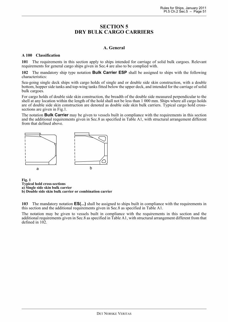
Rules for Ships, January 2011 Pt.5 Ch.2 Sec.5 – Page 51
SECTION 5 DRY BULK CARGO CARRIERS
A. GeneralA 100 Classification101 The requirements in this section apply to ships intended for carriage of solid bulk cargoes. Relevantrequirements for general cargo ships given in Sec.4 are also to be complied with.102 The mandatory ship type notation Bulk Carrier ESP shall be assigned to ships with the followingcharacteristics:Sea-going single deck ships with cargo holds of single and or double side skin construction, with a doublebottom, hopper side tanks and top-wing tanks fitted below the upper deck, and intended for the carriage of solidbulk cargoes. For cargo holds of double side skin construction, the breadth of the double side measured perpendicular to theshell at any location within the length of the hold shall not be less than 1 000 mm. Ships where all cargo holdsare of double side skin construction are denoted as double side skin bulk carriers. Typical cargo hold cross-sections are given in Fig.1.The notation Bulk Carrier may be given to vessels built in compliance with the requirements in this sectionand the additional requirements given in Sec.8 as specified in Table A1, with structural arrangement differentfrom that defined above.
Fig. 1Typical hold cross-sectionsa) Single side skin bulk carrierb) Double side skin bulk carrier or combination carrier
103 The mandatory notation ES(...) shall be assigned to ships built in compliance with the requirements inthis section and the additional requirements given in Sec.8 as specified in Table A1.The notation may be given to vessels built in compliance with the requirements in this section and theadditional requirements given in Sec.8 as specified in Table A1, with structural arrangement different from thatdefined in 102.
ba
DET NORSKE VERITAS

Rules for Ships, January 2011 Pt.5 Ch.2 Sec.5 – Page 52
104 One of the notations BC-A, BC-B or BC-C is mandatory for bulk carriers as defined in UR Z11.2.2,having length L ≥ 150 m and contracted for new construction on or after 1 July 2003. L = ship length as givenby Pt.3 Ch.1 Sec.1 B101.(IACS UR S25.2, Rev. 2)The notation BC-B* may be assigned to General Cargo Carriers, intended for carrying solid bulk cargoes asgiven in Table A2.105 One of the notations HC-A, HC-B, HC-C or HC-B* are mandatory for bulk carriers not defined in 104,i.e. bulk carriers with L < 150 m. The notations HC-A, HC-B, HC-C and HC-B* correspond to the notations BC-A, BC-B, BC-C and BC-B*with the exceptions as given in Table A3.For vessels with the class notation HC-M, requirements in this section apply as given in Table A3 in additionto the requirements in Pt.3 Ch.1 Sec.5.106 The loading conditions listed in 107 to 110 and 112 to 113 shall be used for the checking of Rules criteriaregarding longitudinal strength, as required by Sec.8 C and Pt.3 Ch.1 Sec.5, local strength, capacity anddisposition of ballast tanks and stability. (IACS UR S25.2.2, Rev. 2)107 The notation BC-C implies that the vessel is designed to carry solid bulk cargoes of cargo density lessthan 1.0 t/m3. A homogenous cargo loaded condition where the cargo density corresponds to all cargo holds, includinghatchways, being 100% full, at maximum draught with all ballast tanks empty is required. (IACS UR S25.4.1,Rev. 2)For other required loading conditions, reference is made to Sec.8 A300.108 The notation BC-B implies that the vessel is designed to carry solid bulk cargoes of any density with allholds loaded. In addition to design loading conditions required for notation BC-C (ref. 107), a homogenous cargo loadedcondition with cargo density 3.0 t/m3 and the same filling rate (cargo mass / holds cubic capacity) in all cargoholds at maximum draught with all ballast tanks empty, is required.In cases where the cargo density applied is less than 3.0 t/m3, the max. density of the cargo that the vessel isallowed to carry shall be indicated with the additional notation: Maximum Cargo Density x.y t/m3.(IACS UR S25.4.2, Rev. 2).109 The notation BC-A implies that the vessel is designed to carry solid bulk cargoes of any density, withspecified holds empty at maximum draught.
Table A1 Reference to applicable requirements given in Section 8
Ship type Length, L (m)
Subsection A
Subsection B
Subsection C
Subsection D
Subsection E
Subsection F
Applicable class
notationSingle side skin bulk carrier
L ≥ 150 x x x 1) x 1) x 1) x ES(S)L < 150 - x - - - x ES(S)
Double side skin bulk carrier or combination carrier
L ≥ 150 x - x 1) x 1) x 1) x ES(D)
L < 150 - - - - - x ES(D)
x Applicablex 1) Applicable to vessels intended to carry bulk cargo with density of 1.0 t/m3 or above- Not applicable
(S) Single side skin bulk carrier(D) Double side skin bulk carrier
Subsection A refers to IACS Unified Requirement, S1A, regarding loading manual/loading instrument.Subsection B refers to IACS Unified Requirement, S12, regarding side framesSubsection C refers to IACS Unified Requirement, S17, regarding hull girder strength in flooded conditionSubsection D refers to IACS Unified Requirement, S18, regarding transverse bulkhead strength in flooded condition.Subsection E refers to IACS Unified Requirement, S20, regarding allowable hold loading considering flooding.Subsection F refers to IACS Unified Requirement, S21, regarding hatch cover strength.
DET NORSKE VERITAS
Rules for Ships, January 2011 Pt.5 Ch.2 Sec.5 – Page 53
In addition to design loading conditions required for BC-B (ref. 108), at least one cargo loaded condition withspecified holds empty with cargo density 3.0 t/m3, and the same filling rate (cargo mass / holds cubic capacity)in all loaded holds at maximum draught with all ballast tanks empty, is required.The combination of specified empty holds shall be indicated with the additional notation:Holds a, b,…may be empty.Vessels which are designed with more than one combination of specified empty holds shall have the additionalnotation:Holds a, b,…or c, d,…may be empty.In cases where the cargo density applied is less than 3.0 t/m3, the maximum density of the cargo that the vesselis allowed to carry shall be indicated with the additional notation: Maximum Cargo Density x.y t/m3.(IACS UR S25.4.3, Rev. 2)110 The notation BC-B* implies that the vessel is designed to carry solid bulk cargoes of any density withany hold empty at maximum draught. This requirement is in addition to design loading conditions required for BC-B (ref.108).111 The additional notation No MP shall be assigned to vessels, which have not been designed for loadingand unloading in multiple ports in accordance with 117. I.e. the vessel is not designed to carry maximumallowable cargo hold design mass at reduced draughts. (IACS UR S25.3.i., Rev. 2)112 The vessel shall have a normal ballast (no cargo) condition where:
1) The ballast tanks may be full, partially full or empty. Where partially full option is exercised, the conditionsin Pt.3 Ch.1 Sec.5 B103 shall be complied with.
2) Any cargo hold or holds adapted for the carriage of water ballast at sea shall be empty.3) The propeller shall be fully immersed.4) The trim shall be by the stern and shall not exceed 0.015 L.5) The structures of bottom forward shall be strengthened in accordance with Pt.3 Ch.1 Sec.6 against
slamming for the condition listed above at the lightest forward draught.6) The longitudinal strength requirements shall be met for the conditions listed above.7) The longitudinal strength requirements shall be met with all ballast tanks 100% full.
(IACS UR S25.4.4.1a and 4.4.2a, Rev. 2)113 The vessel shall have a heavy ballast (no cargo) condition where:
1) The ballast tanks may be full, partially full or empty. Where partially full option is exercised, the conditionsin Pt.3 Ch.1 Sec.5 B103 shall be complied with.
2) At least one cargo hold adapted for carriage of water ballast at sea, where required or provided, shall be100% full.
3) The propeller immersion I/D shall be at least 60%.4) The trim shall be by the stern and shall not exceed 0.015L.5) The moulded forward draught in the heavy ballast condition shall not be less than the smaller of 0.03 L or
8 m.6) The longitudinal strength requirements shall be met for the conditions above.7) The longitudinal strength requirements shall be met under a condition with all ballast tanks 100% full and
one cargo hold adapted and designated for the carriage of water ballast at sea, where provided, 100% full.8) Where more than one hold is adapted and designated for the carriage of water ballast at sea, it will not be
required that two or more holds be assumed 100% full simultaneously in the longitudinal strengthassessment, unless such conditions are expected in the heavy ballast condition. Unless each hold isindividually investigated, the designated heavy ballast hold and any/all restrictions for the use of otherballast hold(s) shall be indicated in the loading manual.
I = distance from propeller centerline to the waterlineD = the propeller diameter
(IACS UR S25.4.4.1b and 4.4.2b, Rev. 2)114 The loading conditions given in 107-110 and 112-113 shall be included in the loading manual and shallbe separated into one departure and one arrival condition, where:
— departure condition: with bunker tanks not less than 95% full and other consumables 100%— arrival condition: with 10% of consumables.
DET NORSKE VERITAS
Rules for Ships, January 2011 Pt.5 Ch.2 Sec.5 – Page 54
(IACS UR S25.4.5, Rev. 2)115 The following design loading conditions apply for consideration of local strength as given in C, where:
MH = the actual cargo mass in a cargo hold corresponding to a homogeneously loaded condition atmaximum draught
MFULL = the cargo mass in a cargo hold corresponding to cargo with virtual density (homogeneous mass/holdcubic capacity, minimum 1.0 t/m3) filled to the top of the hatch coaming, MFULL shall not be lessthan MH
MHD = the maximum cargo mass allowed to be carried in a cargo hold according to design loadingcondition(s) with specified holds empty at maximum draught.
(IACS UR S25.5.1, Rev. 2)116 General conditions, applicable for all bulk carriers:
— any cargo hold shall be capable of carrying MFULL, with fuel oil tanks in double bottom, if any, 100% filled,and ballast water tanks in double bottom in way of cargo holds empty, at maximum draught
— any cargo hold shall be capable of carrying minimum 50% of MH with all double bottom tanks in way ofthe cargo hold being empty, at maximum draught
— any cargo hold shall be capable of being empty, with all double bottom tanks in way of cargo hold beingempty, at the deepest ballast draught.
(IACS UR S25.5.2, Rev. 2)117 Condition applicable for all notations, except when notation No MP is assigned:
— any cargo hold shall be capable carrying MFULL with fuel oil tanks in double bottom in way of the cargohold, if any, being 100% full and ballast water tanks in the double bottom in way of the cargo hold beingempty, at 67% of maximum draught
— any cargo hold shall be capable of being empty with all double bottom tanks in way of the cargo hold beingempty, at 83% of maximum draught
— any two adjacent cargo holds shall be capable of carrying MFULL with fuel oil tanks in double bottom inway of the cargo hold, if any, being 100% full and ballast water tanks in the double bottom in way of thecargo hold being empty, at 67% of the maximum draught. This requirement to the mass of cargo and fueloil in double bottom tanks in way of the cargo hold applies also to the condition where the adjacent hold isfilled with ballast, if applicable
— any two adjacent cargo holds shall be capable of being empty, with all double bottom tanks in way of thecargo hold being empty, at 75% of maximum draught.
(IACS UR S25.5.3, Rev. 2)118 Additional conditions applicable for BC-A notation only:
— cargo holds, which are intended to be empty at maximum draught, shall be capable of being empty with alldouble bottom tanks in way of cargo hold also being empty
— cargo holds, which are intended to be loaded with high density cargo, shall be capable of carrying MHDplus 10% of MH, with fuel oil tanks in double bottom, if any, 100% filled, and ballast water tanks in doublebottom in way of cargo holds empty, at maximum draught.In operation, the maximum allowable cargo mass shall be limited to MHD.
— any two adjacent cargo holds which according to a design loading condition may be loaded with the nextholds being empty, shall be capable of carrying 10% of MH in each hold in addition to the maximum cargoload according to that design loading condition, at maximum draught. Fuel oil tanks in double bottom, ifany, shall be 100% filled, and ballast water tanks in double bottom in way of cargo holds shall be empty.In operation the maximum allowable mass shall be limited to the maximum cargo load according to thedesign condition.
(IACS UR S25.5.4, Rev. 2)119 Conditions applicable for notation BC-B* only:
— any cargo hold shall be capable of carrying 1.2 MFULL, with fuel oil tanks in double bottom in way of thecargo hold, if any, being 100% full and ballast water tanks in the double bottom being empty in way of thecargo hold, both at 67% of maximum draught
— any cargo hold shall be capable of being empty with all double bottom tanks in way of the cargo hold alsobeing empty, at maximum draught
— any two adjacent cargo holds shall be capable of carrying 1.1 MFULL, with fuel oil tanks in the doublebottom in way of the cargo hold, if any being 100% full and ballast water tanks in the double bottom in wayof the cargo hold being empty, at 67% of the maximum draught
— any two adjacent cargo holds shall be capable of being empty, with all double bottom tanks in way of the
DET NORSKE VERITAS
Rules for Ships, January 2011 Pt.5 Ch.2 Sec.5 – Page 55
cargo hold being empty, at 75% of maximum draught.
120 Additional conditions applicable during loading and unloading in harbour only:
— any single cargo hold shall be capable of holding the maximum allowable seagoing mass at 67% ofmaximum draught, in harbour condition
— any two adjacent cargo holds shall be capable of carrying MFULL, with fuel oil tanks in the double bottomin way of the cargo hold, if any, being 100% full and ballast water tanks in the double bottom in way of thecargo hold being empty at 67% of maximum draught, in harbour condition
— at reduced draught during loading and unloading in harbour, the maximum allowable mass in a cargo holdmay be increased by 15% of the maximum mass allowed at the maximum draught in sea-going condition,but shall not exceed the mass allowed at maximum draught in the sea-going condition. The minimumrequired mass may be reduced by the same amount.
(IACS UR S25.5.6, Rev. 2)121 Additional conditions applicable for ballast holds if any:
— Cargo holds, which are designed as ballast water holds, shall be capable of being 100% full of ballast waterincluding hatchways, with all double bottom tanks in way of the cargo hold being 100% full, at any heavyballast draught. For ballast holds adjacent to topside wing, hopper and double bottom tanks, it shall bestrengthwise acceptable that the ballast holds are filled when the topside wing, hopper and double bottomtanks are empty.
(IACS UR S25.5.5, Rev. 2)122 The additional notation CSR is mandatory for bulk carriers with the following class notation and length:
— ships with class notation Bulk Carrier ESP and with L ≥ 90 m.
The CSR notation describes that the newbuilding is designed and built according to IACS Common StructuralRules for Bulk Carriers as described in A200.L = ship length as given in Pt.3 Ch.1 Sec.1 B101.123 The additional notation NAUTICUS(Newbuilding) may be given to bulk carriers except incombination with CSR.The notation NAUTICUS (Newbuilding) is mandatory for bulk carriers without CSR notation with thefollowing class notations and lengths as described below:
— BC-B or BC-C with length L > 190 m.— BC-B* or BC-A with length L > 170 m.
The notation NAUTICUS(Newbuilding) is described in Pt.3 Ch.1 Sec.16 and comprises extended fatigue-and direct strength calculations.124 The additional notation IB(3) is mandatory for:
— Ore Carriers with length L > 150 m— Bulk Carriers with length L > 150 m without CSR notation and with loading density above 1.0 t/m3
125 The mandatory ship type and service notation Ore Carrier ESP shall be assigned to sea-going singledeck ships having two longitudinal bulkheads and a double bottom throughout the cargo region, and intendedfor the carriage of ore cargoes in the centre holds only. Typical midship sections are given in Fig. 2.The mandatory notation ES(O) shall be assigned for ships built in accordance with the requirements in B, D,E and F and the additional requirements given in Sec.8 as specified in Table A4.
DET NORSKE VERITAS
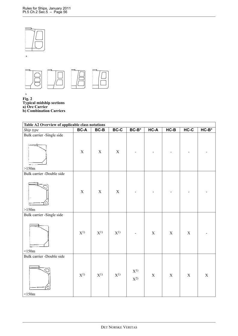
Rules for Ships, January 2011 Pt.5 Ch.2 Sec.5 – Page 56
Fig. 2Typical midship sectionsa) Ore Carrierb) Combination Carriers
Table A2 Overview of applicable class notations Ship type BC-A BC-B BC-C BC-B* HC-A HC-B HC-C HC-B*Bulk carrier -Single side
>150m
X X X - - - - -
Bulk carrier -Double side
>150m
X X X - - - - -
Bulk carrier -Single side
<150m
X1) X1) X1) - X X X -
Bulk carrier -Double side
<150m
X1) X1) X1)X1)
X2)X X X X
a
b
DET NORSKE VERITAS
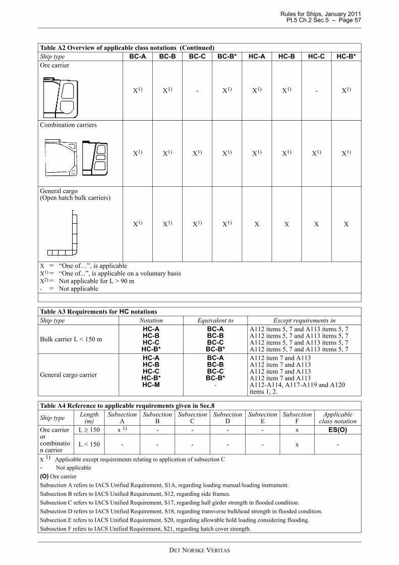
Rules for Ships, January 2011 Pt.5 Ch.2 Sec.5 – Page 57
Ore carrier
X1) X1) - X1) X1) X1) - X1)
Combination carriers
X1) X1) X1) X1) X1) X1) X1) X1)
General cargo(Open hatch bulk carriers)
X1) X1) X1) X1) X X X X
X = “One of…”, is applicableX1) = “One of...”, is applicable on a voluntary basisX2) = Not applicable for L > 90 m- = Not applicable
Table A3 Requirements for HC notationsShip type Notation Equivalent to Except requirements in
Bulk carrier L < 150 mHC-AHC-BHC-CHC-B*
BC-ABC-BBC-CBC-B*
A112 items 5, 7 and A113 items 5, 7A112 items 5, 7 and A113 items 5, 7A112 items 5, 7 and A113 items 5, 7A112 items 5, 7 and A113 items 5, 7
General cargo carrier
HC-AHC-BHC-CHC-B*HC-M
BC-ABC-BBC-CBC-B*
-
A112 item 7 and A113A112 item 7 and A113A112 item 7 and A113A112 item 7 and A113A112-A114, A117-A119 and A120 items 1, 2.
Table A4 Reference to applicable requirements given in Sec.8
Ship type Length (m)
Subsection A
Subsection B
Subsection C
Subsection D
Subsection E
Subsection F
Applicable class notation
Ore carrier or combination carrier
L ≥ 150 x 1) - - - - x ES(O)
L < 150 - - - - - x -
x 1) Applicable except requirements relating to application of subsection C- Not applicable(O) Ore carrierSubsection A refers to IACS Unified Requirement, S1A, regarding loading manual/loading instrument.Subsection B refers to IACS Unified Requirement, S12, regarding side frames.Subsection C refers to IACS Unified Requirement, S17, regarding hull girder strength in flooded condition.Subsection D refers to IACS Unified Requirement, S18, regarding transverse bulkhead strength in flooded condition.Subsection E refers to IACS Unified Requirement, S20, regarding allowable hold loading considering flooding.Subsection F refers to IACS Unified Requirement, S21, regarding hatch cover strength.
Table A2 Overview of applicable class notations (Continued)Ship type BC-A BC-B BC-C BC-B* HC-A HC-B HC-C HC-B*
DET NORSKE VERITAS
Rules for Ships, January 2011 Pt.5 Ch.2 Sec.5 – Page 58
126 Ships built in compliance with the requirements in Ch.11 may be given the class notation DG-B. 127 Ships built in compliance with the requirements in H200 may be given the special feature notation EC.128 Ships built in compliance with the requirements in H300 may be given the special feature notation EL-2.
A 200 Common Structural Rules201 CSR is described in Pt.8 Ch.2, and comprise the scantling requirements for the classification of new bulkcarriers.202 Requirements with respect to strength of the hull structure, including scantlings and testing of integraltanks and selection of hull materials given in Pt.3 Ch.1 and Pt.3 Ch.2 for 90 m < L < 100 m, testing of integraltanks given in Pt.2 Ch.3 Sec.8, and the requirements given in this section are not applicable to vessels withCSR notation.203 The following requirements are in addition covered by the common structural rules and are notapplicable to vessels with CSR notation:
Pt.3 Ch.3 Sec.2 Sub-sections A, B, C, D, E, F, G, HPt.3 Ch.3 Sec.3 Anchoring and Mooring EquipmentPt.3 Ch.3 Sec.6 Opening and Closing AppliancesPt.3 Ch.3 Sec.7 Corrosion PreventionPt.3 Ch.3 Sec.8 Protection of the CrewPt.5 Ch.2 Sec.8 Enhanced Strength for Bulk CarriersPt.2 Ch.3 Sec.8 Structural and Tightness Testing.204 For regions of the structure for which the common structural rules do not apply, the appropriateclassification rules shall be applied. In cases where the common structural rules do not address certain aspectsof the ship's design, the applicable classification rules shall be applied.205 Optional design feature notations described in Pt.3 Ch.1 may be given to vessels with CSR notation.Vessels complying with CSR notation may also be given class notation ES(S) or ES(D) as applicable.
A 300 Documentation301 For ships with notation Ore Carrier having a deadweight capacity above 200 000 DWT, a loadingcondition shall be submitted for approval, specifying loading of the vessel to the full capacity using one pourper hold.The loading condition shall include the loading sequence and specify the average loading rate. Each step in theloading sequence from commencement of cargo loading to full deadweight is reached, step-wise and time-wisesynchronized with the de-ballasting operation, shall be documented.
Guidance note:The average loading rate is defined as rate achieved from start to completion of total cargo loading divided by timeelapsed. Trim pours need not be included in the calculation of average loading rate.
---e-n-d---of---G-u-i-d-a-n-c-e---n-o-t-e---
302 For ships with class notations BC-A, BC-B, BC-C and BC-B*, the loading conditions (separated intoone departure and one arrival condition, ref. A114) shall be submitted for approval. The associated longitudinalstrength calculation(s) and possible special still water bending moment limit (hogging and sagging), see C300,shall be submitted for information in accordance with Pt.3 Ch.1 Sec.1 C200.303 Design loads shall be submitted for information in accordance with Pt.3 Ch.1 Sec.1 C200 as follows:
— design load for holds in terms of maximum cargo mass (MFULL or MHD) in hold in t.
— load limitations for tanks as applicable.
304 Based on the design loading criteria for local strength as given in A115 - A120, on submitted informationgiven in accordance with 200 and on the direct calculations as required in C400, hold mass curves shall beincluded in the loading manual and the loading instrument (see Pt.3 Ch.1 Sec.5).The curves shall show:
— maximum allowable and minimum required mass as a function of draught, still water bending moment limitetc., in sea-going condition as well as during loading and unloading in harbour.
— hold mass curves for each single hold, as well as for any two adjacent holds, shall be included.
Accepted procedures for the determination of load limitations are given in Classification Note No. 31.1“Strength Analysis of Hull Structures in Bulk Carriers and Container Ships”.
DET NORSKE VERITAS
Rules for Ships, January 2011 Pt.5 Ch.2 Sec.5 – Page 59
(IACS UR S25.5.7, Rev. 2)305 Specifications for corrosion prevention systems for water ballast tanks, comprising selection, applicationand maintenance, as defined in Table A1 in Pt.3 Ch.3 Sec.7 shall be submitted for information for BulkCarrier ESP and Ore Carrier ESP. 306 If water ingress detection is arranged the following documentation shall be submitted for approval:
— type test reports unless type approved by the Society— functional description of the alarm system unless type approved by the Society— specification of cargo types for which the ship is intended— location of water ingress detectors— location of alarm panel— power supply arrangement— single line diagrams.
Manuals provided on board shall contain the following information and operational instructions:
1) A description of the equipment for detection and alarm arrangements together with a listing of proceduresfor checking that as far as practicable, each item of equipment is working properly during any stage of shipoperation.
2) Evidence that the equipment has been type tested to the requirements in the performance standard.3) Line diagrams of the detection and alarm system showing the positions of equipment. 4) Installation instructions for orientation, setting, securing, protecting and testing.5) List of cargoes for which the detector is suitable for operating in a 50% seawater slurry mixture.6) Procedures to be followed in the event equipment not functioning correctly.7) Maintenance requirements for equipment and system.
307 For ships with the special feature notation EC, the following shall be submitted for information:
— Supply lines and discharge lines for each cargo hold.— Cleaning equipment and mucking pump as applicable.
308 For ships with the special feature notation EC, the following shall be submitted for approval:
— Hold wash water holding/water ballast tank(s) arrangement.
309 For ships with the special feature notation EL-2, the following shall be submitted for approval:
— Loading sequences according to H301.
Guidance note:For a full definition of the required documentation types, see Pt.0 Ch.3 Sec.2 H112.
---e-n-d---of---G-u-i-d-a-n-c-e---n-o-t-e---
A 400 Structural and leak testing401 Testing shall be in accordance with Pt.2 Ch.3 Sec.8 Table B1.
A 500 Grab cargo handling501 For vessels with class notation General Cargo Carrier intended for grab cargo handling, the optionalclass notation IB-X given in Pt.3 Ch.1 Sec.6 may be assigned.
B. Design LoadsB 100 Design cargo density and angle of repose101 The design load for cargo hold shall be based on the largest cargo mass, MH or MHD (as defined inA115), according to the submitted loading conditions, see A300, for the hold considered, but is in any case notto be taken less than as given by:
MFULL = 1.0 VH (t)
VH = cargo hold volume including hatch in m3.102 The design angle of repose, δ, of bulk cargo is generally not to be taken greater than:
DET NORSKE VERITAS
Rules for Ships, January 2011 Pt.5 Ch.2 Sec.5 – Page 60
Light bulk cargo (grain etc.):δ = 20 degreesHeavy bulk cargo:δ = 35 degreesCement cargo:δ = 25 degrees (associated cargo density
1.35 t/m3).103 For the calculation of plates and stiffeners the cargo density of any hold shall be taken as:For BC-A (ore hold):ρ = (MHD + 0.1 MH) / VH (t/m3)
For BC-A (empty hold), BC-B and BC-C:ρ = MFULL / VH (t/m3)ρ = min 1.0 t/m3
For BC-B*:ρ = 1.2 MFULL / VH (t/m3)
For HC-M:ρ = MFULL / VH (t/m3) in generalρ = MHD / VH (t/m3) for ore loadingρ = min. 1.0 t/m3
For Ore Carrier:ρ = MFULL / VH (t/m3)104 For the direct calculation of girder structures, the design cargo density of any hold shall be taken as thegreater of:For BC-A (ore hold):ρ = (MHD + 0.1 MH) / V (t/m3)
For BC-A (empty hold), BC-B and BC-C:ρ = MFULL / V (t/m3)
For BC-B*:ρ = 1.2 MFULL / V (t/m3)For HC-M:ρ = MFULL / V (t/m3) in generalρ = MHD / V (t/m3) for ore loading
For Ore Carrier:ρ = MFULL / V (t/m3)
V = VH for calculation of cargo bulkhead structures, plates and stiffeners.= VHR for calculation of hold girder structure other than cargo bulkheads
VHR = bulk carrier hold volume below a level 0.3 H + 0.14 bf within 60% of the middle width/length of thehold, and linearly reduced to a level 0.3 H at hold sides and to 0.3 H + 0.07 bf at transverse bulkheads
= ore carrier hold volume below a level 0.4 H + 0.2 bf within the 60% of the middle width of the hold, andlinearly reduced to 0.4 H at the hold sides
H = height of hold in m from inner bottom to top of coamingbf = breadth of hold in m at level 0.3 H (0.4 H for ore carriers) above inner bottom at hold midlength.
B 200 Lateral pressure loads201 The design pressures for local elements (i.e. plates and stiffeners) shall be determined as given in Pt.3Ch.1 Sec.4 using parameters given in 100.202 For direct calculation of girder structures, design pressures shall be determined as given in Pt.3 Ch.1Sec.13 using parameters given in 100.203 For vessels intended to carry steel coils the inner bottom plating and inner bottom longitudinals will beespecially considered.An acceptable calculation method is given in Classification Note No. 31.1.
DET NORSKE VERITAS
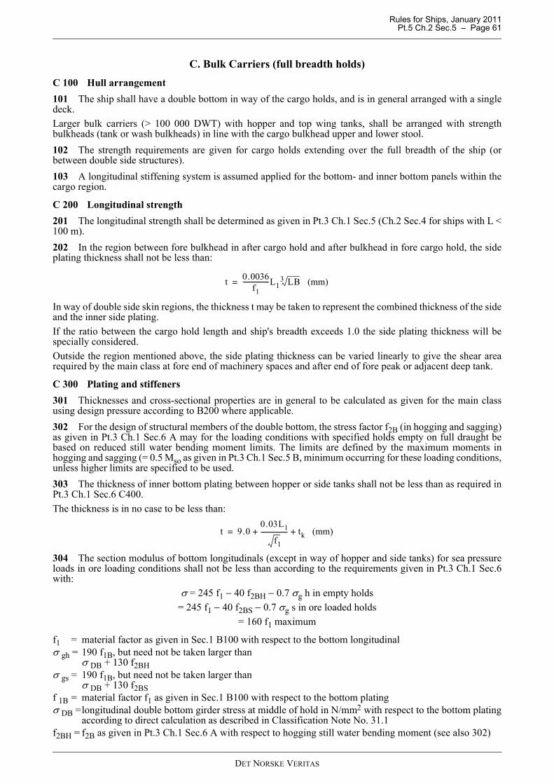
Rules for Ships, January 2011 Pt.5 Ch.2 Sec.5 – Page 61
C. Bulk Carriers (full breadth holds)
C 100 Hull arrangement101 The ship shall have a double bottom in way of the cargo holds, and is in general arranged with a singledeck.Larger bulk carriers (> 100 000 DWT) with hopper and top wing tanks, shall be arranged with strengthbulkheads (tank or wash bulkheads) in line with the cargo bulkhead upper and lower stool.102 The strength requirements are given for cargo holds extending over the full breadth of the ship (orbetween double side structures).103 A longitudinal stiffening system is assumed applied for the bottom- and inner bottom panels within thecargo region.
C 200 Longitudinal strength201 The longitudinal strength shall be determined as given in Pt.3 Ch.1 Sec.5 (Ch.2 Sec.4 for ships with L <100 m).202 In the region between fore bulkhead in after cargo hold and after bulkhead in fore cargo hold, the sideplating thickness shall not be less than:
In way of double side skin regions, the thickness t may be taken to represent the combined thickness of the sideand the inner side plating.If the ratio between the cargo hold length and ship's breadth exceeds 1.0 the side plating thickness will bespecially considered.Outside the region mentioned above, the side plating thickness can be varied linearly to give the shear arearequired by the main class at fore end of machinery spaces and after end of fore peak or adjacent deep tank.
C 300 Plating and stiffeners301 Thicknesses and cross-sectional properties are in general to be calculated as given for the main classusing design pressure according to B200 where applicable.302 For the design of structural members of the double bottom, the stress factor f2B (in hogging and sagging)as given in Pt.3 Ch.1 Sec.6 A may for the loading conditions with specified holds empty on full draught bebased on reduced still water bending moment limits. The limits are defined by the maximum moments inhogging and sagging (= 0.5 Mso as given in Pt.3 Ch.1 Sec.5 B, minimum occurring for these loading conditions,unless higher limits are specified to be used.303 The thickness of inner bottom plating between hopper or side tanks shall not be less than as required inPt.3 Ch.1 Sec.6 C400.The thickness is in no case to be less than:
304 The section modulus of bottom longitudinals (except in way of hopper and side tanks) for sea pressureloads in ore loading conditions shall not be less than according to the requirements given in Pt.3 Ch.1 Sec.6with:
σ = 245 f1 − 40 f2BH − 0.7 σg h in empty holds= 245 f1 − 40 f2BS − 0.7 σg s in ore loaded holds
= 160 f1 maximum
f1 = material factor as given in Sec.1 B100 with respect to the bottom longitudinalσ gh = 190 f1B, but need not be taken larger than
σ DB + 130 f2BHσ gs = 190 f1B, but need not be taken larger than
σ DB + 130 f2BSf 1B = material factor f1 as given in Sec.1 B100 with respect to the bottom platingσ DB =longitudinal double bottom girder stress at middle of hold in N/mm2 with respect to the bottom plating
according to direct calculation as described in Classification Note No. 31.1f2BH = f2B as given in Pt.3 Ch.1 Sec.6 A with respect to hogging still water bending moment (see also 302)
t 0.0036f1
-----------------L1 LB3 (mm)=
t 9.00.03L1
f1----------------- tk (mm)+ +=
DET NORSKE VERITAS
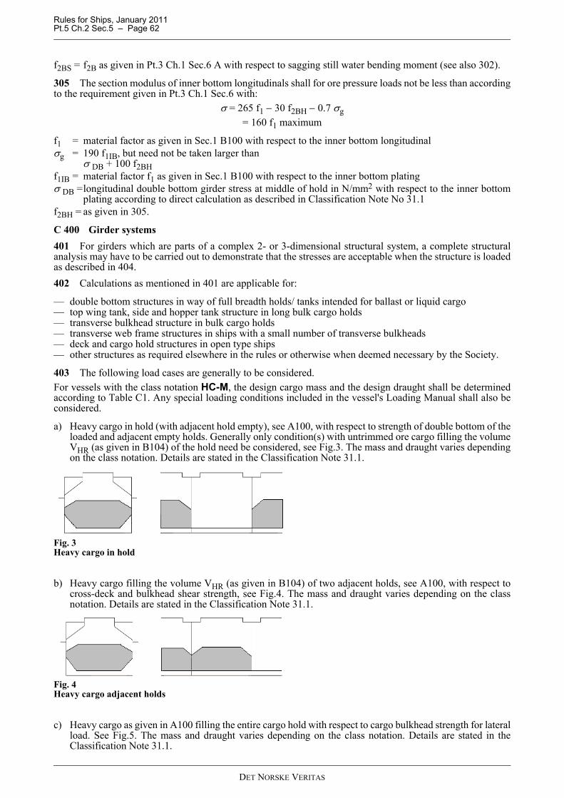
Rules for Ships, January 2011 Pt.5 Ch.2 Sec.5 – Page 62
f2BS = f2B as given in Pt.3 Ch.1 Sec.6 A with respect to sagging still water bending moment (see also 302).
305 The section modulus of inner bottom longitudinals shall for ore pressure loads not be less than accordingto the requirement given in Pt.3 Ch.1 Sec.6 with:
σ = 265 f1 − 30 f2BH − 0.7 σg= 160 f1 maximum
f1 = material factor as given in Sec.1 B100 with respect to the inner bottom longitudinalσg = 190 f1IB, but need not be taken larger than
σ DB + 100 f2BHf1IB = material factor f1 as given in Sec.1 B100 with respect to the inner bottom platingσ DB =longitudinal double bottom girder stress at middle of hold in N/mm2 with respect to the inner bottom
plating according to direct calculation as described in Classification Note No 31.1f2BH = as given in 305.
C 400 Girder systems401 For girders which are parts of a complex 2- or 3-dimensional structural system, a complete structuralanalysis may have to be carried out to demonstrate that the stresses are acceptable when the structure is loadedas described in 404.402 Calculations as mentioned in 401 are applicable for:
— double bottom structures in way of full breadth holds/ tanks intended for ballast or liquid cargo— top wing tank, side and hopper tank structure in long bulk cargo holds— transverse bulkhead structure in bulk cargo holds— transverse web frame structures in ships with a small number of transverse bulkheads— deck and cargo hold structures in open type ships— other structures as required elsewhere in the rules or otherwise when deemed necessary by the Society.
403 The following load cases are generally to be considered.For vessels with the class notation HC-M, the design cargo mass and the design draught shall be determinedaccording to Table C1. Any special loading conditions included in the vessel's Loading Manual shall also beconsidered.
a) Heavy cargo in hold (with adjacent hold empty), see A100, with respect to strength of double bottom of theloaded and adjacent empty holds. Generally only condition(s) with untrimmed ore cargo filling the volumeVHR (as given in B104) of the hold need be considered, see Fig.3. The mass and draught varies dependingon the class notation. Details are stated in the Classification Note 31.1.
Fig. 3Heavy cargo in hold
b) Heavy cargo filling the volume VHR (as given in B104) of two adjacent holds, see A100, with respect tocross-deck and bulkhead shear strength, see Fig.4. The mass and draught varies depending on the classnotation. Details are stated in the Classification Note 31.1.
Fig. 4Heavy cargo adjacent holds
c) Heavy cargo as given in A100 filling the entire cargo hold with respect to cargo bulkhead strength for lateralload. See Fig.5. The mass and draught varies depending on the class notation. Details are stated in theClassification Note 31.1.
DET NORSKE VERITAS
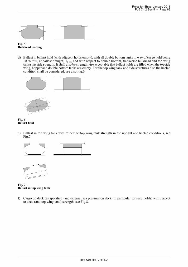
Rules for Ships, January 2011 Pt.5 Ch.2 Sec.5 – Page 63
Fig. 5Bulkhead loading
d) Ballast in ballast hold (with adjacent holds empty), with all double bottom tanks in way of cargo hold being100% full, at ballast draught, THB, and with respect to double bottom, transverse bulkhead and top wingtank/ship side strength. It shall also be strengthwise acceptable that ballast holds are filled when the topsidewing, hopper and double bottom tanks are empty. For the top wing tank and side structures also the heeledcondition shall be considered, see also Fig.6.
Fig. 6Ballast hold
e) Ballast in top wing tank with respect to top wing tank strength in the upright and heeled conditions, seeFig.7.
Fig. 7Ballast in top wing tank
f) Cargo on deck (as specified) and external sea pressure on deck (in particular forward holds) with respectto deck (and top wing tank) strength, see Fig.8.
DET NORSKE VERITAS
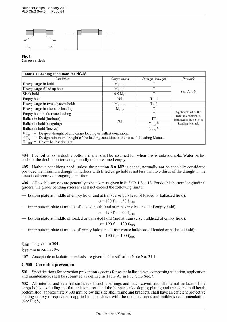
Rules for Ships, January 2011 Pt.5 Ch.2 Sec.5 – Page 64
Fig. 8Cargo on deck
404 Fuel oil tanks in double bottom, if any, shall be assumed full when this is unfavourable. Water ballasttanks in the double bottom are generally to be assumed empty.
405 Harbour conditions need, unless the notation No MP is added, normally not be specially consideredprovided the minimum draught in harbour with filled cargo hold is not less than two thirds of the draught in theassociated approved seagoing condition.
406 Allowable stresses are generally to be taken as given in Pt.3 Ch.1 Sec.13. For double bottom longitudinalgirders, the girder bending stresses shall not exceed the following limits:
— bottom plate at middle of empty hold (and at transverse bulkhead of loaded or ballasted hold):σ = 190 f1 − 130 f2BH
— inner bottom plate at middle of loaded holds (and at transverse bulkhead of empty hold):σ = 190 f1 − 100 f2BH
— bottom plate at middle of loaded or ballasted hold (and at transverse bulkhead of empty hold):σ = 190 f1 − 130 f2BS
— inner bottom plate at middle of empty hold (and at transverse bulkhead of loaded or ballasted hold):σ = 190 f1 − 100 f2BS
f2BH =as given in 304f2BS =as given in 304.
407 Acceptable calculation methods are given in Classification Note No. 31.1.
C 500 Corrosion prevention
501 Specifications for corrosion prevention systems for water ballast tanks, comprising selection, applicationand maintenance, shall be submitted as defined in Table A1 in Pt.3 Ch.3 Sec.7.
502 All internal and external surfaces of hatch coamings and hatch covers and all internal surfaces of thecargo holds, excluding the flat tank top areas and the hopper tanks sloping plating and transverse bulkheadsbottom stool approximately 300 mm below the side shell frame and brackets, shall have an efficient protectivecoating (epoxy or equivalent) applied in accordance with the manufacturer's and builder's recommendation.(See Fig.8)
Table C1 Loading conditions for HC-M Condition Cargo mass Design draught Remark
Heavy cargo in hold MFULL T
ref. A116Heavy cargo filled up hold MFULL TSlack hold 0.5 MH TEmpty hold Nil TB 1)
Heavy cargo in two adjacent holds MFULL TA 2)
Heavy cargo in alternate loading MHD TApplicable when the loading condition is
included in the vessel’s Loading Manual.
Empty hold in alternate loading
Nil
TBallast in hold (harbour) T/3Ballast in hold (seagoing) THB 3)
Ballast in hold (heeled) THB 3)1) TB = Deepest draught of any cargo loading or ballast conditions.2) TA = Design minimum draught of the loading condition in the vessel’s Loading Manual.3) THB = Heavy ballast draught.
DET NORSKE VERITAS
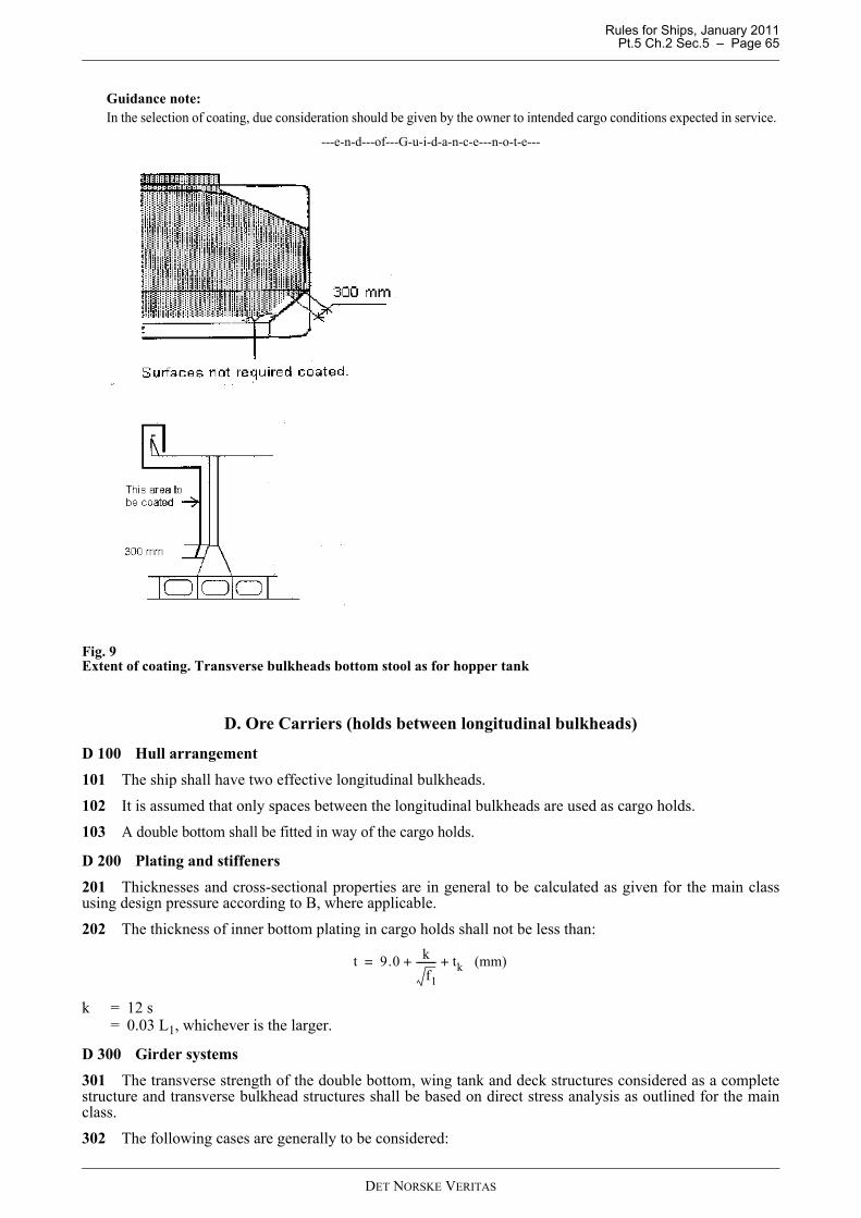
Rules for Ships, January 2011 Pt.5 Ch.2 Sec.5 – Page 65
Guidance note:In the selection of coating, due consideration should be given by the owner to intended cargo conditions expected in service.
---e-n-d---of---G-u-i-d-a-n-c-e---n-o-t-e---
Fig. 9Extent of coating. Transverse bulkheads bottom stool as for hopper tank
D. Ore Carriers (holds between longitudinal bulkheads)
D 100 Hull arrangement
101 The ship shall have two effective longitudinal bulkheads.
102 It is assumed that only spaces between the longitudinal bulkheads are used as cargo holds.103 A double bottom shall be fitted in way of the cargo holds.
D 200 Plating and stiffeners
201 Thicknesses and cross-sectional properties are in general to be calculated as given for the main classusing design pressure according to B, where applicable.
202 The thickness of inner bottom plating in cargo holds shall not be less than:
k = 12 s= 0.03 L1, whichever is the larger.
D 300 Girder systems
301 The transverse strength of the double bottom, wing tank and deck structures considered as a completestructure and transverse bulkhead structures shall be based on direct stress analysis as outlined for the mainclass.
302 The following cases are generally to be considered:
t 9.0 kf1
-------- tk (mm)+ +=
DET NORSKE VERITAS

Rules for Ships, January 2011 Pt.5 Ch.2 Sec.5 – Page 66
a) Heavy ore cargo filling volume VHR (as given in B104) of holds with other spaces empty at draught T, seeFig.10.
Fig. 10Heavy ore hold
b) Ore cargo filling hold completely with adjacent holds/spaces empty at draught T, see Fig.11.
Fig. 11Full ore hold
c) Ballast in ballast tanks with adjacent cargo holds empty at ballast draught TB, see Fig. 12.
Fig. 12Ballast tank
303 A special grillage calculation of the double bottom will normally not be required.
E. Detection of Water Ingress into Cargo Holds Ballast and Dry Spaces, and Availability of Drainage forward Spaces
E 100 Performance requirements101 Bulk carriers shall be fitted with water level detectors giving audible and visual alarms on the navigationbridge:
1) In each cargo hold, one when the water level above the inner bottom in any hold reaches a height of 0.5 mand another at a height not less than 15% of the depth of the cargo hold but not more than 2.0 m.
2) In any ballast tank forward of the collision bulkhead, when the liquid in the tank reaches a level notexceeding 10% of the tank capacity.
3) In any dry or void space other than a chain cable locker, any part of which extends forward of the foremostcargo hold, at a water level of 0.1 m above the deck. Such alarms need not be provided in enclosed spacesthe volume of which does not exceed 0.1% of the ship's maximum displacement volume.
(SOLAS Ch. XII/12)102 The water ingress detection system shall be type tested in accordance with MSC.188 (79) “PerformanceStandards for Water Level Detectors on Bulk Carriers”, and be suitable for the cargoes intended.
Guidance note:The appendix to the Classification Certificate will contain information as to which cargoes the systems are approved for.
---e-n-d---of---G-u-i-d-a-n-c-e---n-o-t-e---
DET NORSKE VERITAS
Rules for Ships, January 2011 Pt.5 Ch.2 Sec.5 – Page 67
E 200 Installation201 The sensors shall be located in a protected position that is in communication with the after part of thecargo hold or tank and or space, such that the position of the sensor detects the level that is representative ofthe levels in the actual hold space or tank.These sensors shall be located:
— either as close to the centre line as practicable, or— at both the port and starboard sides.
202 The detector installation shall not inhibit the use of any sounding pipe or other water level gauging devicefor cargo holds or other spaces.203 Detectors and equipment shall be installed where they are accessible for survey, maintenance and repair.204 Any filter element fitted to detectors shall be capable of being cleaned before loading.205 Electrical cables and any associated equipment installed in cargo holds shall be protected from damageby cargoes or mechanical handling equipment associated with bulk carrier operations, such as in tubes of robustconstruction or in similar protected locations.206 The part of the electrical system which has circuitry in the cargo area shall be arranged intrinsically safe.207 The power supply shall be in accordance with Pt.4 Ch.9 Sec.3 B200.
E 300 Survey on board301 After installation the system is subject to survey consisting of:
— inspection of the installation— demonstration of facilities for filter cleaning— demonstration of facilities for testing of the detector— test of all alarm loops— test of the alarm panel functions.
E 400 Availability of drainage forward spaces 401 On bulk carriers, the means for draining and pumping ballast tanks forward of the collision bulkhead,and bilges of dry spaces, any part of which extends forward of the foremost cargo hold, shall be capable ofbeing brought into operation from a readily accessible enclosed space. The location of which shall be accessiblefrom the navigation bridge or propulsion machinery control position, without need for traversing exposedfreeboard or superstructure decks. (SOLAS reg.XII/13)This does not apply to the enclosed spaces the volume of which does not exceed 0.1% of the ship's maximumdisplacement volume. Nor does it apply to the chain cable lockers.
Guidance note:Where pipes serving such tanks or bilges pierce the collision bulkhead, as an alternative to the valve control specifiedin Pt.4 Ch.6 Sec.3 A402, valve operation by means of remotely operated actuators may be accepted, provided that thelocation of such valve controls complies with this regulation.
---e-n-d---of---G-u-i-d-a-n-c-e---n-o-t-e---
402 The dewatering system for ballast tanks forward of the collision bulkhead and for bilges of dry spacesany part of which extends forward of the foremost cargo hold shall be designed to remove water from theforward spaces at a rate of not less than 320A m3/h, where A is the cross sectional area in m2 of the largest airpipe or ventilator pipe connected from the exposed deck to a closed forward space that is required to bedewatered by these arrangements.(IACS UR M65)403 The installation and survey on board shall be in accordance with Pt.4 Ch.6 Secs.4, 6 and 7 for bilgesystems.
F. Requirements for the Fitting of a Forecastle for Bulk Carriers, Ore Carriers and Combination Carriers
F 100 Application and definition101 These requirements apply to all bulk carriers, combination carriers and ore carriers as defined in A102and A123.
DET NORSKE VERITAS
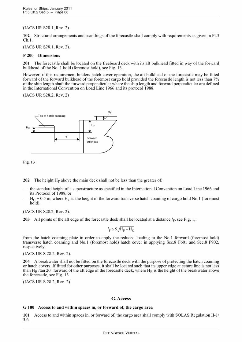
Rules for Ships, January 2011 Pt.5 Ch.2 Sec.5 – Page 68
(IACS UR S28.1, Rev. 2).
102 Structural arrangements and scantlings of the forecastle shall comply with requirements as given in Pt.3Ch.1.(IACS UR S28.1, Rev. 2).
F 200 Dimensions
201 The forecastle shall be located on the freeboard deck with its aft bulkhead fitted in way of the forwardbulkhead of the No. 1 hold (foremost hold), see Fig. 13.However, if this requirement hinders hatch cover operation, the aft bulkhead of the forecastle may be fittedforward of the forward bulkhead of the foremost cargo hold provided the forecastle length is not less than 7%of the ship length abaft the forward perpendicular where the ship length and forward perpendicular are definedin the International Convention on Load Line 1966 and its protocol 1988.(IACS UR S28.2, Rev. 2)
Fig. 13
202 The height HF above the main deck shall not be less than the greater of:
— the standard height of a superstructure as specified in the International Convention on Load Line 1966 andits Protocol of 1988, or
— HC + 0.5 m, where HC is the height of the forward transverse hatch coaming of cargo hold No.1 (foremosthold).
(IACS UR S28.2, Rev. 2).
203 All points of the aft edge of the forecastle deck shall be located at a distance lF, see Fig. 1,:
from the hatch coaming plate in order to apply the reduced loading to the No.1 forward (foremost hold)transverse hatch coaming and No.1 (foremost hold) hatch cover in applying Sec.8 F601 and Sec.8 F902,respectively.(IACS UR S 28.2, Rev. 2).
204 A breakwater shall not be fitted on the forecastle deck with the purpose of protecting the hatch coamingor hatch covers. If fitted for other purposes, it shall be located such that its upper edge at centre line is not lessthan HB /tan 20° forward of the aft edge of the forecastle deck, where HB is the height of the breakwater abovethe forecastle, see Fig. 13.(IACS UR S 28.2, Rev. 2).
G. Access
G 100 Access to and within spaces in, or forward of, the cargo area
101 Access to and within spaces in, or forward of, the cargo area shall comply with SOLAS Regulation II-1/3.6.
Forwardbulkhead
HB
HF
lF
HC
Top of hatch coaming
lF 5 HF HC–≤
DET NORSKE VERITAS

Rules for Ships, January 2011 Pt.5 Ch.2 Sec.5 – Page 69
H. Optional Class Notations EC and EL-2H 100 General101 The special feature notation EL-2 is intended for Ore Carriers.
H 200 Optional class notation EC201 The vessel shall be built with double side skin construction as given in A102. In addition, hatch coverswhich are not accessible for cleaning in open position shall be of double side skin construction.202 Separate or combined hold wash water holding/water ballast tank(s) of adequate size for temporarystorage shall be fitted. The tank(s) shall be filled by common wash water discharge line on deck, connected toindividual hold branch lines, and discharged directly overboard by drop surface valve(s). At the aft of eachcargo hold a valve for connection of flexible hose shall be fitted at the end of the individual hold discharge linebranched down. Similar arrangement may be accepted. Small hatch with coaming, giving unobstructed access to the holding tank, for internal cleaning, shall be fittedon upper deck. Close to access hatch air and water supply for internal cleaning shall be provided.Provision shall be made so that deck washings can be collected and guided into the storage tank(s).203 Water and air supply lines shall be provided in all cargo holds at easily accessible and protectedlocations. In addition the water and air supply lines shall be fitted with hose connection valves at lower end andisolation valves at deck. The hold discharge line shall be provided from the bottom of hold to upper deck with hose connection valvesat both ends.204 Fixed or portable cleaning system shall be provided.
Guidance note:Due to poor experience and need of substantial maintenance of fixed guns when handling dusty cargoes, portablecleaning guns of the jet type (air and water powered) are recommended.
---e-n-d---of---G-u-i-d-a-n-c-e---n-o-t-e---
The general service pump and the service air compressor shall have adequate capacity and pressure forsimultaneous operation of at least two cleaning guns, and one air-driven mucking pump. If fixed cleaningsystem, the general service pump and service air compressor must have adequate capacity to operate thesystem.205 Handling davit for air-driven mucking pump and cargo residue shall be provided. Small hatch with coaming, giving unobstructed access to the inner bottom for removal of cargo residue shallbe fitted on upper deck at the cross deck at the aft end of each cargo hold with air outlet close by.206 The cargo holds shall be coated with abrasive resistant painting.207 All ladders in cargo holds shall be located in separate trunks.
H 300 Optional class notation EL-2301 Vessels with the optional class notation EL-2 shall be able to handle average loading rates as given inTable H1, unless higher rates are specified and provided as part of the documentation for approval. The average loading rate is defined as rate achieved from start to completion of total cargo loading divided bytime elapsed. Special consideration shall be given if loading with two or more loaders simultaneous is specified and providedas part of the documentation for approval. Relevant loading sequences for coal and ore as applicable, with average loading rates in accordance with TableH1, or higher specified average loading rates, for the following conditions shall be defined:
— homogeneous condition (one and two grade loading), if applicable — relevant part loading conditions, if applicable— alternate conditions, if applicable.
Each step in the loading sequences from commencement of cargo loading to full deadweight is reached, step-wise and time-wise synchronized with the de-ballasting operation, shall be documented. Each time the loadingequipment changes position to a new cargo hold is defined as a step. Time-wise synchronized in this context means that the de-ballasting is completed within the same time as theloading step.The typical loading sequences shall also be developed to not exceed applicable strength limitations.
DET NORSKE VERITAS
Rules for Ships, January 2011 Pt.5 Ch.2 Sec.5 – Page 70
Guidance note 1:Such loading sequences may be decisive for the vessels strength although they are considered port conditions. I.e. theymay give the highest net pressure on the bottom construction and give the highest bending moment and shear forcesand thus represent a design condition that should be addressed in the FEM loading conditions. For that reason alsointermediate steps will have to be demonstrated, but only for design purposes.
---e-n-d---of---G-u-i-d-a-n-c-e---n-o-t-e---
For all relevant loading sequences, considering one, two or more loaders acting simultaneously as applicable,a summary of all steps shall be included with at least the following information included:
— how much cargo is filled in each cargo hold during the different steps — how much ballast is discharged from each ballast tank during the different steps — the maximum still water bending moment and shear force at the end of each step — the ship's trim and draught at the end of each step— the ship's draught aft and forward, trim and air-draught, if restrictions are applicable— the ship's local strength criteria for single and adjacent hold loading.
Guidance note 2:As guidance for ore carriers the mean draught at berth prior to loading should not be less than 60% of scantling draughttaking possible air-draught restriction into consideration
If the Master deems necessary due to operational reasons to deviate from the approved loading sequencecalculations with ratings according to EL-2 he may do so provided he is in compliance with SOLAS Ch.VIPt.B, Reg.7.3 and on this condition agree with the terminal on a new loading plan.302 The de-ballast capacity of the vessel at loading berth prior to commencement of loading, includingarrangement of ballast tanks and relevant piping system, shall meet the requirements for the average loadingrates as specified in Table H1.If average loading rate is specified to be higher than those given in Table H1, the loading operation shall notbe interrupted due to de-ballast operations. The vessel shall be fitted with a separate stripping system. To enhance de-ballasting and stripping the trim shallbe by stern during the whole operation.303 The vessel shall be designed such that minimum 100% of maximum permissible cargo intake per cargohold can be loaded in one pour.304 Inner bottom strength shall be according to the requirements as given in Pt.8 Ch.2/Chapter 12 Sec.1 orPt.3 Ch.1 Sec.6 H300, as applicable.305 The vessel shall be fitted with a remote sounding for water ballast and fuel oil storage tanks and draughtreading system with an on-line interface into the software of the onboard loading computer.306 Check of local strength for single and adjacent hold loading pattern shall be integrated into the softwareof the onboard loading computer.
Table H1 Design loading rates DWT Average loading rate, t/h
> 250 000 16 000250 000 – 220 000 14 000
DET NORSKE VERITAS
Rules for Ships, January 2011 Pt.5 Ch.2 Sec.6 – Page 71
SECTION 6 CONTAINER CARRIERS
A. General
A 100 Classification101 The requirements in this section apply to ships intended for carriage of standard freight containers forgeneral cargo at predetermined positions on board, in holds and/or on weather deck. Relevant requirements forgeneral cargo ships given in Sec.4 are also to be complied with.Subsection B need in general not be considered for container carriers with length L < 100 m.102 Ships exclusively intended for the carriage of containers and arranged with cell guides in holds and builtin compliance with relevant requirements specified in the following may be given the class notationContainer Carrier.103 Ships intended also for other purposes, while arranged, strengthened and equipped for carriage ofcontainers on deck and/or in holds and built in compliance with relevant requirements specified in thefollowing, may be given the class notation CONTAINER in addition to the other notations (e.g. GeneralCargo Carrier CONTAINER).Containers carried on deck or in holds on such ships shall be secured by an approved method. The securingarrangement shall be approved and only equipment certified or type approved by the Society shall be used forsecuring. However, loose container securing equipment need only be carried onboard to the extent the ship iscarrying containers.Ships intended to carry containers with dangerous goods (packed goods, dry bulk or portable tanks) shallcomply with the requirements of Ch.11.104 For ships with class notations as given in 102 and 103, a notation of the maximum number of twenty-foot equivalent units (TEU) that may be carried will be added, e.g. 1750 TEU. 105 The additional notation NAUTICUS(Newbuilding) is mandatory for ships with the class notation:Container Carrier with length, L, greater than 190 m.L = Ship length as given in Pt.3 Ch.1 Sec.1 B101.The notation NAUTICUS(Newbuilding) is described in Pt.3 Ch.1 Sec.16 and comprises extended fatigue -and direct strength calculations. Areas for fatigue calculations are further described in C308, and areas fordirect strength calculations are described in C402.
A 200 Scope201 The following matters are covered by the classification:
— arrangements for stowing and securing of containers in holds and on weather deck— design, construction and installation of permanent supporting fittings and structures for the containers— design and construction of removable container securing equipment For equipment produced in series the
Society's Type Approval scheme may be applied— instructions (Manual) for stowing and securing of the containers— hull structure of ships intended for carriage of standard freight containers for general cargo in cellular cargo
holds as given in B.
202 When an instrument is installed as a supplement to the Stowage and Securing manual, this shall beapproved by the Society.
A 300 Assumptions301 The classification of the ship is based on the assumptions that:
— the approved “Container Stowage and Securing Manual” is kept available on board for the stowage andsecuring of container cargo
— all required equipment for the securing of containers are of strength, design and make approved by theSociety for its purpose
— the containers are stowed and secured in accordance with the approved Manual and the approved stowageand securing plans
— all container securing equipment is properly maintained and repaired— damaged equipment is replaced by equipment which is type approved and of at least the same strength rating— the approved instrument for stowage and securing of containers is checked at regular intervals.
DET NORSKE VERITAS

Rules for Ships, January 2011 Pt.5 Ch.2 Sec.6 – Page 72
302 The above assumptions for the classification shall be stated in the approved “Container Stowage andSecuring Manual” onboard.
A 400 Definitions401 Terms:
— Container: Freight container according to ISO-standard, or other specially approved container.— Container stack: Containers which are stacked vertically and secured horizontally by stackers, lashings etc.,
see Fig. 1.— Container block: A number of container stacks interconnected and secured horizontally by bridge stackers,
see Fig. 2.— Minimum breaking load: Tested minimum breaking strength of wire rope, chain, rod or other member in
accordance with rule specifications.— Non-rigid securing arrangements: Securing arrangements where the stiffness of containers influence
support forces and internal forces in the containers, e.g. lashing arrangements including lashing bridges andcontainer stanchions.
— Rigid securing arrangements: Securing arrangements where the stiffness of the containers do not influencesupport forces and internal forces in the containers, e.g. cellular containment arrangements.
— Container securing equipment: Loose and fixed equipment used for securing and supporting of containers.— Container support fittings: Fittings welded into tank tops, decks, bulkheads or hatch covers (i.e. fittings
that form an integral part of the ship structure).— Container securing devices: Includes container securing equipment and container support fittings.— Cell guides: An arrangement in holds or on deck of fixed vertical guide rails for support of containers.— Maximum securing load, MSL: The maximum allowable load on container securing devices, based on
testing or calculations.
Fig. 1Individual container stacks with lashings
Fig. 2Container block with lashing and sideway supports
DET NORSKE VERITAS

Rules for Ships, January 2011 Pt.5 Ch.2 Sec.6 – Page 73
A 500 Documentation requirements
501 Documentation shall be submitted as required by Table A1.
502 For general requirements to documentation, see Pt.0 Ch.3 Sec.1.
503 For a full definition of documentation types, see Pt.0 Ch.3 Sec.2.
A 600 Container stowage
601 Calculations of maximum forces and stresses in container supports, and adjoining hull structures (e.g.hatch covers and supporting coamings and girders), cell guides, lashings, containers etc. shall be carried out.Acceptable methods for such calculations are outlined in Classification Note No. 32.2 "Strength Analysis ofContainer Securing Arrangements".
602 Procedures for certification of lashing computer systems are given in Classification Note 32.2 Appendix A.
A 700 Certification of container securing fittings
701 Container support fittings, cell guides, lashing bridges and container stanchions shall be delivered withDet Norske Veritas' material certificates.
702 Type approval will be according to the general scheme outlined in Pt.1 Ch.1 Sec.4 and in CertificationNote 1.1. The Society will issue a Type Approval Certificate valid for 4 years and the product will be enteredin the “List of Type Approved Products”.
703 Container securing equipment shall be delivered with works material certificates from the manufacturer.
704 In addition to the material certificates required in 601 and 603, all loose and fixed container securingequipment and support fittings shall be delivered with product certificates. The certificates should contain atleast the following information:
— name of manufacturer— type designation of item— material(s)— identification marking— test procedure— test results of strength tests (breaking load and proof load) if applicable— results of non-destructive examination if applicable— allowable working load.
Equipment shall be either type approved or case-by-case approved.
Table A1 – Documentation requirementsObject/Function Documentation type Additional description For approval (AP) or
For information (FI)
Ship hull
H052 – Midship section drawing
Including stack weights and minimum mass in one typical 40-foot bay on scantling draught.
AP
H110 – Loading manualIncluding maximum hull girder still water torsional moment, and unsymmetrical design loading conditions, if applicable.
AP
H180 – Cargo securing manual APH190 – Container stowage and securing manual
AP
Cell guides
C030 – Detailed drawingIncluding nominal cell guide/container clearances and specified building tolerances of container cell guides.
AP
C010 – Design criteria
When cargo loading conditions which are unsymmetrical about the ships' centre line are intended, information on the minimum diagonal cell guide/container clearance required for loading/unloading may be requested.
FI
Permanent container support fittings on hatch covers
C030 – Detailed drawingAP
DET NORSKE VERITAS

Rules for Ships, January 2011 Pt.5 Ch.2 Sec.6 – Page 74
B. Longitudinal and Local StrengthB 100 Definitions101 Symbols
f1 = as given in Sec.1 B with respect to the considered member= 1.51 for NV-40 steel for vessels assigned the notation Container Carrier.
This material factor shall also be applied in Pt.3 Ch.1 Sec.5 C302 - 304.f*2 = longitudinal stress parameter, applicable for transversely stiffened plates and longitudinal
stiffeners of the hull cross-section, given by:
The value of f*2 shall in general be taken equal to the f2 as given in Pt.3 Ch.1 Sec.6 A and Sec.8A within 0.4 L amidship. The f*2 shall be determined for hull cross-sections at positions wherethe hull girder section modulus has been checked according to 208. The f*2 may be taken equalto 0.5 f1 within 0.1 L from AP or FP unless the hull girder section modulus has been checkedin this area according to 208.Between the given positions, f*2, shall be determined by linear interpolation.
f* 2B = f*2 with respect to the hull girder section modulus at bottomf* 2D = f*2 with respect to the hull girder modulus at deckf* 2BH = f*2 with respect to the hull girder section modulus at bottom and hogging momentf* 2BS = f*2 with respect to the hull girder section modulus at bottom and sagging momentkl = parameter for determination of allowable stresses for laterally loaded plates
= 3.5 (1 − f*2 / f1). The kl is, however, not to be taken larger than: 5 x/L − 1x = distance in m from L/2 to considered position
= 0.2 L minimum= 0.4 L maximum
kl D = kl with respect to f*2Dkl B = kl with respect to f*2B
Z =
MS = design still water bending moment at considered section in kNmk sm, M SO = as given in Pt.3 Ch.1 Sec.5 B100MW = Rule wave bending moment at considered section in kNm given in Pt.3 Ch.1 Sec.5 B. Hogging
or sagging moment shall be chosen in relation to the applied still water moment.
B 200 Longitudinal and buckling strength201 The longitudinal and buckling hull girder strength are in general to be determined as given in Pt.3 Ch.1Sec.5 and Sec.13.The design Stillwater bending moments, MS, and Stillwater shear forces, Qs, may, subject to acceptance in eachcase, be based on the envelope curve representing all relevant full- and part load cargo- and ballast conditionsas given in Pt.3 Ch.1 Sec.5 B101.202 Ships with class notation Container Carrier shall have sufficient global hull girder hogging bendingstrength to resist the defined Rule extreme design loads as defined 205 without suffering hull girder collapse,ductile plate fracture and compartment flooding.After the extreme design wave loading, the vessel shall stay afloat and maintain its overall integrity. Permanentsets and buckles in limited areas are accepted, as long as the global hull girder strength and stiffness is notviolated.
ZB = section modulus at bottom in cm3 of hull girder as built at section considered,
ZD = section modulus at deck in cm3 of hull girder as built at section considered
f*2
5.7 Ms Mw+( )Z
------------------------------------=
DET NORSKE VERITAS

Rules for Ships, January 2011 Pt.5 Ch.2 Sec.6 – Page 75
For illustration, figure showing a ship hull in an extreme hogging state with cross-sectional vertical moment Mand shear force Q distribution.203 All relevant cross-sections shall be assessed, also out-side 0.4 L. Hull cross-sections with transverselystiffened areas, such as engine rooms, are considered to be especially important to be checked.204 The moment M to be used in the criteria should be evaluated at the mid-position between twoneighbouring transverse girders in the cross-section considered.205 The vertical hogging bending moment criterion to be complied with is:
γsMMS + γw
MMW ≤ MU/γmwhere
γSM = Load factor for Stillwater hogging bending moment
= 1.0γW
M = Load factor for Wave hogging bending moment = 1.25 forward of 0.65L from AP = 1.5 aft of 0.58L from APTo be given by linear interpolation between 0.58L from AP and 0.65L from AP.
γmM = Factor for Ultimate moment capacity
= 1.0 MS = Stillwater hogging bending moment as given in 201 in the considered hull sectionMW = Wave hogging bending moment as given in Pt.3 Ch.1 Sec.5 B 201 in considered hull section without
adjustments to kwm MU = Ultimate hull girder hogging bending moment for a section in a pure vertical bending modus. The MU is calculated as summing up the longitudinal loads carried by each element in section at hull girdercollapse. An acceptable method for assessing the MU value is to apply the DNV HULS model:
where
Pi - = Axial load in element no. i at hull girder collapse (Pi = (EA)eff-i εi
g-collapse) zi - = Distance from hull-section neutral axis to centre of area of element no. i at hull girder collapse.
The neutral axis position shall be shifted due to local buckling and collapse of individual elementsin the hull-section.
(EA)eff-i - = Axial stiffness of element no. i accounting for buckling of plating and stiffeners (pre-collapsestiffness)
K - = Total number of assumed elements in hull section (typical stiffened panels, girders etc.)εi - = Axial strain of centre of area of element no. i at hull girder collapse (ei = εi
g-collapse) the collapsestrain for each element follows the displacement hypothesis assumed for the hull section
σ - = Axial stress in hull-section z - = Vertical co-ordinate in hull-section measured from neutral axis.
Guidance note:Panel Ultimate Limit Strength (PULS) is used for individual element ultimate capacity and stiffness assessments.PULS is a DNV computer program using non-linear plate theory to calculate a stiffened plate field's ultimate bucklingstrength. It treats the entire, stiffened plate field as an integrated unit, allowing for internal redistribution of thestresses.
---e-n-d---of---G-u-i-d-a-n-c-e---n-o-t-e---
∑∫ ∑ −− =
=== iiiefftionhull
K
iiiU zEAzPdAzM εσ )(
sec 1(5.9)
DET NORSKE VERITAS
Rules for Ships, January 2011 Pt.5 Ch.2 Sec.6 – Page 76
206 Global ULS – hull girder criteria shall be checked using as built scantlings unless otherwise stated in theRules. 207 Alternative advanced methods, i.e. such as non-linear FE model analyses or equivalent for assessing theultimate hull girder capacities MU will be considered by the Society on a case by case basis.208 The requirements given in 209 and 210 will normally be satisfied if calculated with respect to the midshipsection and characteristic sections of the end ship regions. Cross- sections where the arrangement oflongitudinal material changes is of particular interest. As a minimum sections at or close to the aft- and forwardquarterlength positions and at the ends of the open cargo region must be evaluated.209 The requirement for section modulus of the hull girder about the transverse axis is for any section to betaken as given in Pt.3 Ch.1 Sec.5 C303 with σl = 175 f 1 (N/mm2).
Guidance note:It is advised that the still water bending moment M S values, if based on Pt.3 Ch.1 Sec.5 B101, are taken with a marginof, say 5%, relative to the moment envelope of the ship's design loading conditions.
---e-n-d---of---G-u-i-d-a-n-c-e---n-o-t-e---
210 The combined normal stress of vertical and horizontal hull girder bending and of torsional moment shall ingeneral not exceed 195 f1 N/mm2. In the deck and hatch coaming, the combined stress shall not exceed 225 f1. Thecombined stress shall be taken as:
σ = | σSTAT + σDYN | (N/mm2)
σSTAT = σS + σSTσDYN = σW + σ WH + σWTσS = MS (zn − za) 105 / IσW = MWR (zn − za) 105 / IM WR = reduced vertical wave bending moment to be considered for the combined response
= 0.45 MW in generalI = moment of inertia in cm4 of hull girder about the horizontal axis at section consideredzn and za = as given in Sec.1 Bσ WH = M WH ya 105 / IHIH = moment of inertia in cm4 of hull girder about the vertical axis at section consideredya = distance in m from centreline to position consideredM WH = as given in Pt.3 Ch.1 Sec.5 B205σ ST = warping stress and stress due to warping deformations in N/mm2 at position considered for the
given still water torsional moment distribution, M STσ WT = warping stress and stress due to warping deformations at position considered due to the wave
torque, MWTM WT = as given in Pt.3 Ch.1 Sec.5 B206M ST = design still water torsional moment in kNm over ship length
= 0.3 LB2 (kNm) minimum.For the purpose of calculating stresses due to still water torsion, a still water torsional distribution equal to thewave torsional distribution may be assumed.
Guidance note:The still water- and wave induced warping stresses and stress due to warping deformations may be determined basedon prismatic beam- or global coarse mesh finite element calculations. Acceptable methods for calculation of torsionresponse is outlined in Classification Notes 31.7.
---e-n-d---of---G-u-i-d-a-n-c-e---n-o-t-e---
211 The curvatures of upper deck hatch corners are in general to be taken as given in Pt.3 Ch.1 Sec.5 E500and in 212-213 below. In special cases the stress level in the corner region may be required to be documentedto be acceptable by special calculations.212 The curvature of streamlined hatch corners at side at the aft end of the open deck region is generally tobe as given in Pt.3 Ch.1 Sec.5 E501 with transverse extension not less than:
f1 = as given in B for deck plating in area consideredAlternatively double (or single) curvature corner shapes may be accepted provided the radius of curvature atthe hatch side is not less than 1.8 a (m).For extent of local reinforcement of deck plating at hatch corners, see Pt.3 Ch.1 Sec.8 A405.
a 0.020B f1 (m)=
DET NORSKE VERITAS
Rules for Ships, January 2011 Pt.5 Ch.2 Sec.6 – Page 77
213 For cross decks, the radius of rounded corners is generally not to be less than:
k = 0.16 for hatch corners at side= 0.10 for hatch corners for longitudinal deck girders
f1 = f1 as given in B for deck plating in area consideredw = width of cross deck in m.For extent of local reinforcement of deck plating at hatch corners, see Pt.3 Ch.1 Sec.8 A405.When a corner with double curvature is desired, a reduction of the inside radius may be considered.214 For the design of structural members of the double bottom, the hull girder compressive longitudinalstress may, subject to acceptance in each case, be based on a reduced hogging still water bending moment Mh,reduced, corresponding to the maximum allowable bending moment at scantling draught. The allowable designbending moment Mh, reduced, at scantling draught T, and the allowable design bending moment, Mh, at a lowerdraught, TMh, full shall be stated in the Appendix to Classification Certificate. The combination of reduceddraught and allowable design bending moment Mh will be checked. For draughts between TMh, full and TS, thepermissible hogging bending moment shall be linearly interpolated between the values of Mh,full andMh,reduced, and the permissible bending moment as a function of the draught shall be implemented in thevessel’s loading computer. The reduced still water bending moment, Mh,reduced shall not to be taken less than2/3 of Mh,full.
Guidance note:This consideration may only be applied if the difference between the stresses caused by full hogging moment and thereduced hogging moment
is greater than the difference in double bottom stresses at the reduced draught and at the full draught. The differencein double bottom stresses may be based on an evaluation of the change in the net pressure on the double bottom.
---e-n-d---of---G-u-i-d-a-n-c-e---n-o-t-e---
B 300 Plating and stiffeners301 Thicknesses and cross-sectional properties are in general to be calculated as given for the main class,considering also the requirements given for cellular container holds given in C.The allowable stress may be based on the stillwater bending moment as given in B201.302 Bottom plating and stiffeners shall de designed as given in Pt.3 Ch.1 Sec.6 with allowable stresses forapplicable rule items taken as follows (reference to said section given):C302: Bottom and bilge plating
σ = (175 + 40 klB) f1 − 120 f* 2B, maximum (120 + 40 klB) f 1 where transversely stiffened
= (120 + 40 klB) f1 where longitudinally stiffened
C401: Inner bottom plating
σ = (200 + 20 klB) f1 − 110 f* 2B, maximum (140 + 20 klB) f 1 where transversely stiffened
= (140 + 20 klB) f1 where longitudinally stiffened
C501: Plating in double bottom floors and longitudinal girders
σ = (190 + 30 klB) f1 − 120 f* 2B, maximum (130 + 30 klB) f 1 where transversely stiffened
= (130 + 30 klB) f1 where longitudinally stiffened= 160 f1 for floors
C701: Bottom longitudinals
σ = allowable stress, maximum 160 f1= 225 f1 − 130 f*2B (zn − za) / zn for single bottom longitudinals= 225 f1 − 130 f*2B − 0.7 σdb for double bottom longitudinals= as given in C307 (this chapter) for bottom longitudinals of double bottoms in cellular container holds
C801: Inner bottom longitudinalsThe section modulus of inner bottom longitudinals exposed to tank pressure on the stiffener side only in the
r k w 0.8+( ) f1 (m)=
( )reduced 2BH,2BH, *f - *f130=Δ hoggswσ
DET NORSKE VERITAS

Rules for Ships, January 2011 Pt.5 Ch.2 Sec.6 – Page 78
double bottom shall not be less than according to the requirements given in Pt.3 Ch.1 Sec.6 with:
σ = allowable stress, maximum 160 f1= lesser of:
2 · (225 f1 − 100 f*2BH − 0.7 σdb) (at middle of stiffener) or(225 f1 − 100 f*2BS − 0.7 σdb) (at end of stiffener)with σdb = 20 f1 N/mm2 in general.
C901: Stiffening of double bottom floors and girders
σ = allowable stress, maximum 160 f1= 225 f1 − 110 f*2B for longitudinal stiffeners= 160 f1 for transverse and vertical stiffeners in general.
Allowable stresses for stiffening of double bottom girders exposed to tank pressure on the stiffener side onlyshall be taken as lesser of:
σ = 2 · (225 f1 − 110 f*2BH) (at middle of stiffener) orσ = (225 f1 − 110 f*2BS) (at end of stiffener)
maximum 160 f1.
303 Side longitudinals shall de designed as given in Pt.3 Ch.1 Sec.7 C301 with allowable stresses taken asfollows:
σ = 225 f1 − 130 f*2 (zn − z a) / zn, maximum 160 f1.= 130 f1, maximum for longitudinals supported by side verticals in single deck constructions.
304 Deck plating and stiffeners shall de designed as given in Pt.3 Ch.1 Sec.8 with allowable stresses forapplicable rule items taken as follows (references to said section given):C102: Strength deck plating
σ = allowable stress= (175 + 40 kl D) f1 − 120 f* 2D, maximum
(120 + 40 kl D) f 1 where transversely stiffened= (120 + 40 kl D) f1 where longitudinally stiffened.
C301: Deck longitudinals
σ = allowable stress= 225 f1 − 130 f*2D, maximum160 f1 for strength deck and long superstructures and effective deck houses
above strength deck= 225 f1 − 130 f*2D (zn − z a) / zn, maximum 160 f1 for continuous decks below strength deck.
Allowable stresses for deck longitudinals below the neutral axis exposed to tank pressure on the stiffener sideonly shall be taken as lesser of:
σ = 2 · (225 f1 − 130 f*2BH (zn – za)/zn*)) (at middle of stiffener) orσ = (225 f1 − 130 f*2BS (zn – za)/zn) (at end of stiffener)
maximum 160 f1.
In combination with heeled condition pressures p9 and p11,σ = 160 f1 shall generally be used.305 The arrangement of longitudinal stiffeners of the strength deck shall be taken as given in Pt.3 Ch.1 Sec.8A403 with longitudinals arranged to be continuous within the complete open cargo hold length for ship lengths> 100 m.306 Bulkhead plating and stiffeners shall be designed as given in Pt.3 Ch.1 Sec.9 with allowable stresses forapplicable rule items taken as follows:C201: Bulkhead longitudinals
σ = 225 f1 − 130 f*2 (zn − z a) / zn, maximum 160 f1
Allowable stresses for bulkhead longitudinals below the neutral axis exposed to tank pressure on the stiffenerside shall be taken as lesser of:
σ = 2 · (225 f1 − 130 f*2BH (zn – za)/zn*)) (at middle of stiffener) orσ = (225 f1 − 130 f*2BS (zn – za)/zn) (at end of stiffener)
maximum 160 f1.
DET NORSKE VERITAS

Rules for Ships, January 2011 Pt.5 Ch.2 Sec.6 – Page 79
For longitudinals, σ = 160 f1 shall be used in any case in combination with heeled condition pressures p6 and p7.307 Simple girders shall be designed as given in Pt.3 Ch.1 with allowable stresses for applicable rule itemstaken as follows:Sec.8 D201 and Sec.9 D201:
σ = 190 f1 − 130 f*2 (zn − z a) / zn, maximum 160 f1 for continuous longitudinal girders= 160 f1 for other girders
For longitudinal girders, σ = 160 f1 shall in any case be used in combination with heeled condition pressures.
B 400 Strength evaluation of wave breaker and supporting structure401 Where a wave breaker is fitted in the forward part of the ship, protecting the containers from damage dueto green sea on deck, the scantlings of plating, stiffeners and girders, and the supporting deck structure shouldbe evaluated based on requirements given in the following.402 The design load on the wave breaker structure shall be taken in accordance with the design load forunprotected front bulkhead of superstructure, Pt.3 Ch.1 Sec.10 Table C1.403 Plating and stiffeners shall be designed as given in Pt.3 Ch.1 Sec.10 D100 with allowable stress as givenin Table B1.404 Wave breaker girder system, and its supporting structure shall be designed based on a direct calculationtaking into account the efficiency of the provided deck support below the wave breaker.Allowable stresses shall be taken as given in Table B1:
Where relevant, the plating of the wave breaker shall satisfy the buckling strength requirements given in Pt.3Ch.1 Sec.13 B applying usage factors:
η = 0.8 for plate panels in uni-axial compression = 0.85 for plate panels in bi-axial compression = 0.85 for plate panels in shear.
C. Cellular Container Hold StructuresC 100 General101 The structural requirements given in C200 to C400 are primarily applicable for container ships withcellular container holds and with a predominantly hogging hull girder still water bending moment. For othership types with container transportation capability, e.g. open hatch bulk carriers, the structural design is mainlyto be based on the rule requirements for the principal type and service class notation (e.g. General CargoCarrier BC-A, or Bulk Carrier BC-A).
C 200 Design loads201 Cargo holds for container cargo are generally to be considered for design loads and design loadassumptions as given in 202 to 205.202 It is assumed that the maximum allowable stack weight is defined for every 20′ and 40′ (45′ ) containerstack position of every cargo space. If the maximum stack weight has not been specified, the maximumallowable stack weight shall be taken equal to max. container weight multiplied with no of tiers.203 The maximum cargo mass of any hold, deck area or cargo space is, unless a lower mass limit is specified,to be taken as the sum of maximum 20′ (if applicable) container stack weights for the cargo space considered.204 A uniform distribution of container mass within each container stack shall generally be assumed, unlessdiffering mass distributions are specified.205 In the full draught condition with minimum mass of cargo in a given 40′ (45′ ) container bay, theminimum cargo mass shall be assumed for the container hold and deck region between any transversewatertight bulkhead and support bulkhead. Outside of this region container hold and deck spaces shall beassumed to have maximum cargo mass in accordance with 203.Within the minimum cargo region, any one 40′ (45′ ) container bay of a cargo hold (or equivalent) and deck
Table B1 Allowable stressesWave breaker and supporting structure
σ 160 f1τ 90 f1
DET NORSKE VERITAS
Rules for Ships, January 2011 Pt.5 Ch.2 Sec.6 – Page 80
area above are in general to be assumed empty. In the remaining spaces (in hold and deck above) of theminimum cargo region, the container mass shall not be greater than the maximum cargo mass based on 40′ (45′)container stowage (if applicable, 20′ container stowage) given according to 202.Alternatively specified minimum cargo limits may be considered.
C 300 Plates and stiffeners301 Thicknesses and cross-section properties are with the exceptions given in 302 to 308 to be as given forthe main class.302 The minimum thickness of web and flange of stiffeners of ballast tanks shall be taken as given in Pt.3Ch.1 Sec.7 C302 and Sec.9 C202 with k = 0.01 L1.For sea chest boundaries (including top and partial bulkheads), see Pt.3 Ch.1 Sec.6 C500 and C900.303 The thickness of webs, flanges and brackets of girders of double bottom tanks shall be taken as given inPt.3 Ch.1 Sec.6 C502 with:
k = 0.03 L1 for centre girder up to 2 m above keel platek = 0.015 L1 for other girders and remaining part of centre girderk = 0.05 L1 for sea chest boundaries (including top and partial bulkheads).
304 The thickness of stiffeners and girders including webs, flanges and brackets of ballast tanks of the side-and bulkhead structures of the cargo region as otherwise given by the requirements in Pt.3 Ch.1 Sec.7 D101and Sec.9 D101 shall not be less than:
k = 0.01 L1
305 The thickness of the inner shell plating shall be as given in Pt.3 Ch.1 Sec.9 C100 with k = 0.01, and therequirement of C104 disregarded.306 The minimum plate thickness of transverse bulkheads which are required for gas tightness only, shall betaken as given in Pt.3 Ch.1 Sec.9 C102 with k = 0.307 The section modulus of bottom longitudinals within the width of the double bottom shall not be less thanaccording to the requirements given in Pt.3 Ch.1 Sec.6 with:
σ = 245 f1 − 40 f*2BH − 0.7 σg
f1 = material factor as given in Sec.1 B100 with respect to the bottom longitudinalσg = 190 f1B, but need not be taken larger than
σ DB + 130 f*2BHf 1B = material factor f1 as given in Sec.1 B100 with respect to the bottom platingσ DB = longitudinal double bottom stress with respect to the bottom plating in the middle of the minimum
loaded hold for load case LC2 as given in 404f*2BH = f*2B as given in B with respect to the hogging still water bending moment.
Guidance note:If a direct double bottom calculation has not been carried out and the bottom longitudinal section modulusrequirement based on the standard rule formulation given in Pt.3 Ch.1 Sec.6 C701 has not been complied with, thebottom longitudinal profile as proposed may still be accepted provided the calculated longitudinal double bottomstress σdb, of the bottom plating in the mid part of the hold for the load cases LC2, LC3 as given in 404 does not exceedthe following limit:
σ db = 350 f1 − 1.43 (σ + 130 f*2BH) (N/mm2)
σ =
Z = section modulus (cm3) of proposed bottom longitudinall, s, p, wk = as given in Pt.3 Ch.1 Sec.6
In addition it is assumed that the σdb based on the direct calculation shall not exceed the following limit:σ db = 190 f1 − 130 f*2BH (N/mm2)
---e-n-d---of---G-u-i-d-a-n-c-e---n-o-t-e---
308 The minimum thickness of the side plating shall be as given in Pt.3 Ch.1 Sec.7 C102 with k = 0.037 and
t 5.0 kf1
-------- tk (mm)+ +=
83l2spwkZ
------------------------
DET NORSKE VERITAS

Rules for Ships, January 2011 Pt.5 Ch.2 Sec.6 – Page 81
Pt.3 Ch.1 Sec.7 C103 with T = Td = design draught.309 For ships as mentioned in A105 fatigue strength assessment is in general to be carried out for endstructures of longitudinals in bottom, inner bottom, side, inner side, longitudinal bulkheads and strength deckin the cargo area, as described in Pt.3 Ch.1 Sec.16. The warping stresses should in general be taken intoaccount.In addition, a fatigue life evaluation of the hatch corners shall be carried out.310 At support of stiffeners, the net shear connection area (a0,S) and the net connection area of the webstiffener (a0,N) shall normally not be less than:a0,S = cS k (l - 0.5 s) s p (cm2)a0,N= cN k (l - 0.5 s) s p (cm2)where
a0,S = required net shear area between lug(s) or collar plate and longitudinala0,N = required net connection area between the stiffener and the web stiffener welded to the longitudinal.k, l, s, p = as defined in Pt.3 Ch.1 Sec.11 C401
c = according to Pt.3 Ch.1 Sec.11 Table C4= 1.0 for T-profiles
Ashear = net shear area of the lug(s)/collar plates in the connectionAws = net area of the web stiffener on top Kws = stress distribution factor as given in Table C1.
Corrosion addition as specified in Pt.3 Ch.1 Sec.2 D200 is not included in the formulae for a0,S and a0,N, andshall be added where relevant.The weld area, aS and aN, of the connections shall not be less than:
whereak = corrosion addition corresponding to tk.
C 400 Girder systems401 The scantlings of the girder structures of the double bottom, transverse bulkhead and side structure ofcontainer holds may have to be based on direct stress analysis in accordance with Pt.3 Ch.1 Sec.13.
Guidance note:The direct calculations should generally be carried out as three-dimensional beam and/or finite element calculationscovering double bottom and sides and transverse bulkhead structures as applicable. For unsymmetrical loadingconditions a full breadth model (extending from side to side) may be required unless the anti-symmetric boundarycondition may be applied for representation of the dynamic loads of LC3 and LC4 given in 404. For the model, vertical supports may generally be assumed at the intersection of the elements representing thetransverse watertight bulkheads and the double side structure.The longitudinal extent of the model should cover the considered container hold length and extending to the middleof the adjacent holds where the symmetry boundary condition may generally be assumed. If the symmetry conditionmay be assumed for structure and loads at the mid-length position of the considered hold, the total model length need
Table C1 Values of KwsL profile T profile
Direct connection 1.3 0.9Direct connection with lug 1.2 1.0Slit type 1.15 1.0
cS cAshear
Kws Aws Ashear+-------------------------------------------⎝ ⎠
⎛ ⎞=
cNc3
------- 1Ashear
Kws Aws Ashear+-------------------------------------------–⎝ ⎠
⎛ ⎞=
aS1.15 a0 S, f1
fw------------------------------- ak+=
aN1.4 a0 N, f1
fw---------------------------- ak+=
DET NORSKE VERITAS

Rules for Ships, January 2011 Pt.5 Ch.2 Sec.6 – Page 82
only extend over two half hold lengths.---e-n-d---of---G-u-i-d-a-n-c-e---n-o-t-e---
402 Direct calculations by use of finite element methods are mandatory for vessels described in A105 andshall be carried out in accordance with principles described in Pt.3 Ch.1 Sec.12 B, in addition to the principlesdescribed here and elsewhere in the rules.The following calculations are at least to be considered:
— support bulkhead including panel/girder and pillar structures— typical web frame at position between support bulkhead and watertight bulkhead— longitudinal double bottom girders.
In addition, stresses in laterally loaded local stiffeners subject to relative deformation between girders arenormally to be considered.403 For ships which give rise to warping response, a coarse mesh finite element model of the entire ship hulllength may be required for torsional calculations.404 The following design load cases are in general to be considered, see also Fig. 3 to Fig.8:
LC1: Maximum mass of cargo (20′ containers as relevant) in considered hold in seagoing upright condition atreduced draught. This condition is primarily intended for dimensioning of bottom transverse membersof support bulkheads. If there is no slim cell guide in hold for exclusive stowage of 20′ container stack,then the number of 20′ container tiers in the stack shall be in accordance with the container stowage plan.The adjacent holds shall be assumed empty, and the draught is generally not to be considered larger than0.8T.
Fig. 3Load case 1
LC2: Minimum mass of cargo in hold between adjacent watertight bulkheads which is comprised of one 40′bay empty in hold and deck above in the full draught condition. This condition is primarily intended fordimensioning of double bottom and supporting pillar bulkhead(s). The adjacent cargo holds shall beassumed filled with maximum mass of cargo (40′ container cargo as relevant).
Fig. 4Load case 2
LC3: Maximum mass of cargo in hold and on deck between watertight bulkheads, i.e. the same loaddescription as LC1, but in heeled condition. This condition is primarily intended for dimensioning of theupper part of side structure and support bulkhead. The adjacent holds shall be assumed empty, and thedraught is generally not to be considered larger than 0.8T in sea going heeled condition.
W.L. =
0.8T
WTBHD
WTBHD
SupportBHD
SupportBHD
SupportBHD
W.L.
1.0T
WTBHD
WTBHD
SupportBHD
SupportBHD
SupportBHD
DET NORSKE VERITAS
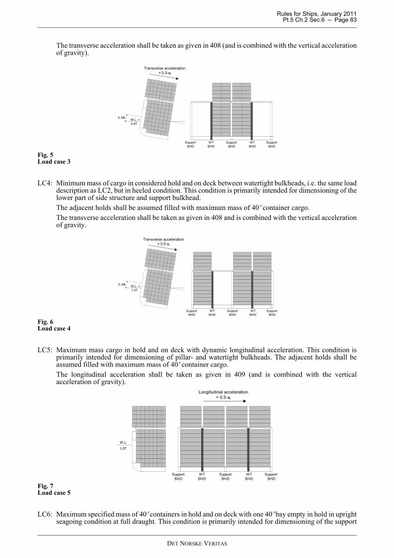
Rules for Ships, January 2011 Pt.5 Ch.2 Sec.6 – Page 83
The transverse acceleration shall be taken as given in 408 (and is combined with the vertical accelerationof gravity).
Fig. 5Load case 3
LC4: Minimum mass of cargo in considered hold and on deck between watertight bulkheads, i.e. the same loaddescription as LC2, but in heeled condition. This condition is primarily intended for dimensioning of thelower part of side structure and support bulkhead.The adjacent holds shall be assumed filled with maximum mass of 40′ container cargo.The transverse acceleration shall be taken as given in 408 and is combined with the vertical accelerationof gravity.
Fig. 6Load case 4
LC5: Maximum mass cargo in hold and on deck with dynamic longitudinal acceleration. This condition isprimarily intended for dimensioning of pillar- and watertight bulkheads. The adjacent holds shall beassumed filled with maximum mass of 40′ container cargo.The longitudinal acceleration shall be taken as given in 409 (and is combined with the verticalacceleration of gravity).
Fig. 7Load case 5
LC6: Maximum specified mass of 40′ containers in hold and on deck with one 40′ bay empty in hold in uprightseagoing condition at full draught. This condition is primarily intended for dimensioning of the support
W.L. =0.8T
WTBHD
WTBHD
SupportBHD
SupportBHD
SupportBHD
0.5Φ
Transverse acceleration = 0.5·at
W.L. =1.0T
0.5Φ
WTBHD
WTBHD
SupportBHD
SupportBHD
SupportBHD
Transverse acceleration = 0.5·at
WTBHD
WTBHD
SupportBHD
SupportBHD
SupportBHD
Longitudinal acceleration = 0.5·al
W.L.
1.0T
DET NORSKE VERITAS
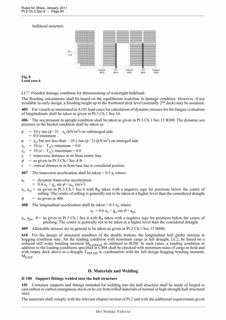
Rules for Ships, January 2011 Pt.5 Ch.2 Sec.6 – Page 84
bulkhead structure.
Fig. 8Load case 6
LC7: Flooded damage condition for dimensioning of watertight bulkhead.The flooding calculations shall be based on the equilibrium waterline in damage condition. However, if notavailable in early design, a flooding height up to the freeboard deck level (normally 2nd deck) may be assumed.405 For vessels as mentioned in A105 load cases for calculation of dynamic stresses for the fatigue evaluationof longitudinals shall be taken as given in Pt.3 Ch.1 Sec.16.406 The sea pressure in upright condition shall be taken as given in Pt.3 Ch.1 Sec.13 B300. The dynamic seapressure in the heeled condition shall be taken as:
p = 10 y tan (φ / 2) – zs (kN/m2) on submerged side= 0.0 minimum
p = ze, but not less than – 10 y tan (φ / 2) (kN/m2) on emerged sidezs = 10 (z − TA), minimum = 0.0ze = 10 (z − TA), maximum = 0.0y = transverse distance in m from centre lineφ = as given in Pt.3 Ch.1 Sec.4 Bz = vertical distance in m from base line to considered position.
407 The transverse acceleration shall be taken = 0.5 at where:
at = dynamic transverse acceleration= 0.4 ay + go sin φ + ary (m/s2)
ay, ary = as given in Pt.3 Ch.1 Sec.4 with RR taken with a negative sign for positions below the centre ofrolling. The centre of rolling is generally not to be taken at a higher level than the considered draught
φ = as given in 406.408 The longitudinal acceleration shall be taken = 0.5 al, where:
al = 0.6 ax + go sin θ + apx
ax, apx, θ = as given in Pt.3 Ch.1 Sec.4 with RP taken with a negative sign for positions below the centre ofpitching. The centre is generally not to be taken at a higher level than the considered draught.
409 Allowable stresses are in general to be taken as given in Pt.3 Ch.1 Sec.13 B400.410 For the design of structural members of the double bottom, the longitudinal hull girder stresses inhogging condition may, for the loading condition with minimum cargo at full draught, LC2, be based on areduced still water bending moment Mh,reduced as outlined in B208. In such cases, a loading condition inaddition to the loading conditions specified in C404 shall be checked with minimum mass of cargo in hold andwith empty deck above at a draught TMH,full in combination with the full design hogging bending moment,Mh,full.
D. Materials and Welding D 100 Support fittings welded into the hull structure101 Container supports and fittings intended for welding into the hull structure shall be made of forged orcast carbon or carbon-manganese steels or be cut from rolled materials of normal or high strength hull structuralsteel.The materials shall comply with the relevant chapter/section of Pt.2 and with the additional requirements given
WTBHD
WTBHD
SupportBHD
SupportBHD
SupportBHD
W.L.
1.0T
DET NORSKE VERITAS

Rules for Ships, January 2011 Pt.5 Ch.2 Sec.6 – Page 85
in this subsection.102 The carbon content of cast and forged steel shall not exceed 0.24%.103 Specified minimum yield stress for castings and forgings shall not exceed 400 N/mm2. Charpy V-notchtests for castings and forgings shall be carried out at the temperature required for hull structural materials in theadjacent area or at 0°C, whichever is the lower. Minimum absorbed energy shall comply with the requirementsgiven in the relevant chapter/section of Pt.2.
D 200 Container securing equipment201 Container securing equipment (not intended for welding into the hull structure) shall be made of forgedor cast steel or machined from rolled material. For devices and members produced without any welds, ferriticnodular cast iron may be used, subject to special approval. The materials shall comply with a recognisednational or international standard, and are also to meet the additional requirements given in this subsection.Specifications deviating from the requirements given in this subsection may be evaluated on the basis ofdocumented experience or comprehensive test results.It may be required that the materials are delivered from manufacturers approved by the Society.202 Carbon and carbon-manganese steels shall be fully killed.203 For items produced without any welding the following apply:For carbon and carbon-manganese steels the C-content shall not exceed 0.40%.For alloy steels the C-content shall not exceed 0.45%.When welding is used in the production, the chemical composition shall be appropriate for the welding process,dimensions and heat treatment process in question.For thicknesses up to about 30 mm, when flash welded and heat treated according to 300 after welding, a carboncontent up to 0.35% for carbon and carbon-manganese steels and 0.40% for alloy steels may be accepted.In other respects the chemical composition shall comply with the recognised standard.204 Specified minimum yield stress for carbon and carbon-manganese steels shall not exceed 400 N/mm2
when normalised, and 480 N/mm2 when quenched and tempered. For alloy steels the specified minimum yieldstress shall not exceed 750 N/mm2. Alloy steel with specified yield stress up to 800 N/mm2 may, however, beaccepted upon special consideration of the material properties and its application in each case.Charpy V-notch impact test shall be carried out at 0°C for container securing devices to be used under weatherdeck. For container securing devices to be used above weather deck, the test shall be carried out at -20°C or atthe vessel design operating temperature, whichever is the lower. The average value of the absorbed energy shallbe at least as shown in Fig. 9. At least 3 specimens shall be tested. One individual value may be less than therequired average value, however, not less than 70% of this average. For rolled and forged materials, testspecimens may be taken in the longitudinal direction. In castings the direction of test specimens is optional.For tests performed at temperatures below –20°C, the required absorbed energy may be specially considered. In other respects the mechanical properties shall comply with the recognised standard.
Fig. 9Charpy V-notch, requirements for steel
D 300 Heat treatment301 Castings and forgings of carbon and carbon-manganese steel shall be supplied in the normalised orquenched and tempered condition. Rolled materials shall be supplied in the heat treatment condition prescribedin the recognised specification.
DET NORSKE VERITAS
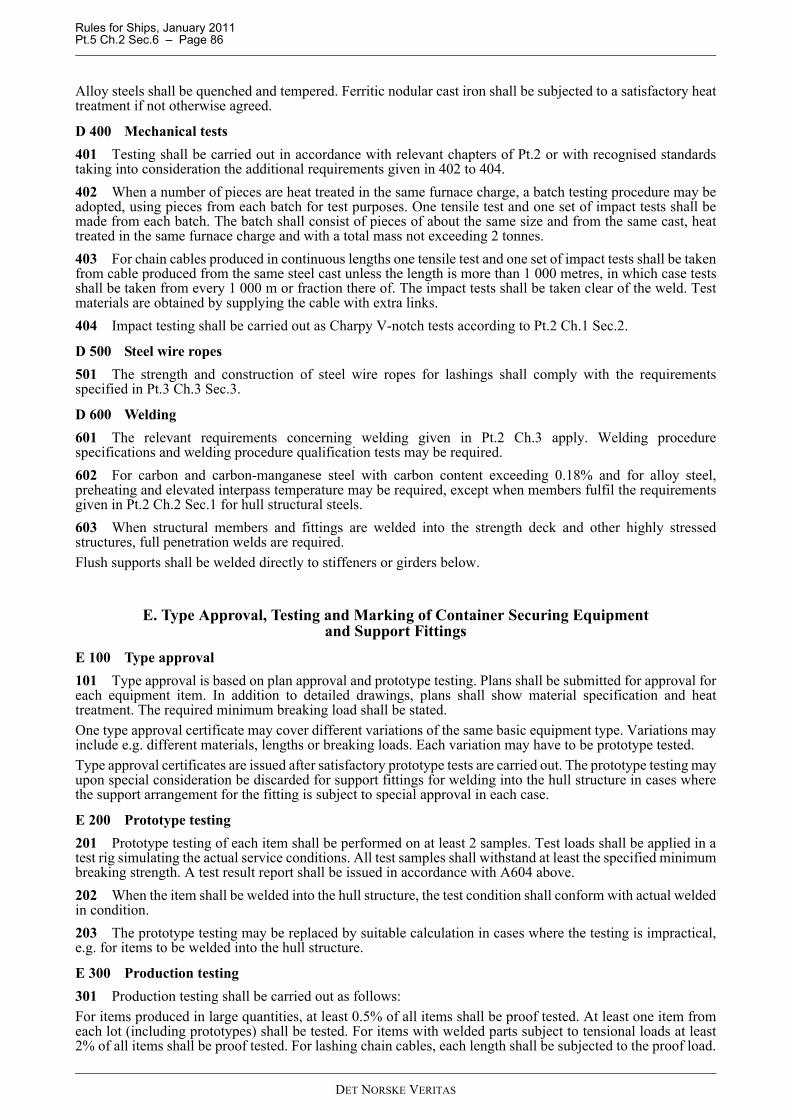
Rules for Ships, January 2011 Pt.5 Ch.2 Sec.6 – Page 86
Alloy steels shall be quenched and tempered. Ferritic nodular cast iron shall be subjected to a satisfactory heattreatment if not otherwise agreed.
D 400 Mechanical tests401 Testing shall be carried out in accordance with relevant chapters of Pt.2 or with recognised standardstaking into consideration the additional requirements given in 402 to 404.402 When a number of pieces are heat treated in the same furnace charge, a batch testing procedure may beadopted, using pieces from each batch for test purposes. One tensile test and one set of impact tests shall bemade from each batch. The batch shall consist of pieces of about the same size and from the same cast, heattreated in the same furnace charge and with a total mass not exceeding 2 tonnes.403 For chain cables produced in continuous lengths one tensile test and one set of impact tests shall be takenfrom cable produced from the same steel cast unless the length is more than 1 000 metres, in which case testsshall be taken from every 1 000 m or fraction there of. The impact tests shall be taken clear of the weld. Testmaterials are obtained by supplying the cable with extra links.404 Impact testing shall be carried out as Charpy V-notch tests according to Pt.2 Ch.1 Sec.2.
D 500 Steel wire ropes501 The strength and construction of steel wire ropes for lashings shall comply with the requirementsspecified in Pt.3 Ch.3 Sec.3.
D 600 Welding601 The relevant requirements concerning welding given in Pt.2 Ch.3 apply. Welding procedurespecifications and welding procedure qualification tests may be required.602 For carbon and carbon-manganese steel with carbon content exceeding 0.18% and for alloy steel,preheating and elevated interpass temperature may be required, except when members fulfil the requirementsgiven in Pt.2 Ch.2 Sec.1 for hull structural steels.603 When structural members and fittings are welded into the strength deck and other highly stressedstructures, full penetration welds are required.Flush supports shall be welded directly to stiffeners or girders below.
E. Type Approval, Testing and Marking of Container Securing Equipment and Support Fittings
E 100 Type approval101 Type approval is based on plan approval and prototype testing. Plans shall be submitted for approval foreach equipment item. In addition to detailed drawings, plans shall show material specification and heattreatment. The required minimum breaking load shall be stated.One type approval certificate may cover different variations of the same basic equipment type. Variations mayinclude e.g. different materials, lengths or breaking loads. Each variation may have to be prototype tested.Type approval certificates are issued after satisfactory prototype tests are carried out. The prototype testing mayupon special consideration be discarded for support fittings for welding into the hull structure in cases wherethe support arrangement for the fitting is subject to special approval in each case.
E 200 Prototype testing201 Prototype testing of each item shall be performed on at least 2 samples. Test loads shall be applied in atest rig simulating the actual service conditions. All test samples shall withstand at least the specified minimumbreaking strength. A test result report shall be issued in accordance with A604 above.202 When the item shall be welded into the hull structure, the test condition shall conform with actual weldedin condition.203 The prototype testing may be replaced by suitable calculation in cases where the testing is impractical,e.g. for items to be welded into the hull structure.
E 300 Production testing301 Production testing shall be carried out as follows:For items produced in large quantities, at least 0.5% of all items shall be proof tested. At least one item fromeach lot (including prototypes) shall be tested. For items with welded parts subject to tensional loads at least2% of all items shall be proof tested. For lashing chain cables, each length shall be subjected to the proof load.
DET NORSKE VERITAS
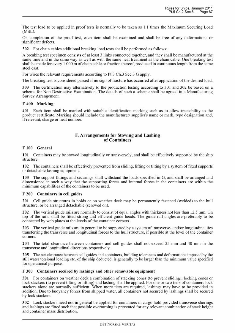
Rules for Ships, January 2011 Pt.5 Ch.2 Sec.6 – Page 87
The test load to be applied in proof tests is normally to be taken as 1.1 times the Maximum Securing Load(MSL).On completion of the proof test, each item shall be examined and shall be free of any deformations orsignificant defects.302 For chain cables additional breaking load tests shall be performed as follows:A breaking test specimen consists of at least 3 links connected together, and they shall be manufactured at thesame time and in the same way as well as with the same heat treatment as the chain cable. One breaking testshall be made for every 1 000 m of chain cable or fraction thereof, produced in continuous length from the samesteel cast.For wires the relevant requirements according to Pt.3 Ch.3 Sec.3 G apply.The breaking test is considered passed if no sign of fracture has occurred after application of the desired load.303 The certification may alternatively to the production testing according to 301 and 302 be based on ascheme for Non-Destructive Examination. The details of such a scheme shall be agreed in a ManufacturingSurvey Arrangement.
E 400 Marking401 Each item shall be marked with suitable identification marking such as to allow traceability to theproduct certificate. Marking should include the manufacturer/ supplier's name or mark, type designation and,if relevant, charge or heat number.
F. Arrangements for Stowing and Lashing of Containers
F 100 General101 Containers may be stowed longitudinally or transversely, and shall be effectively supported by the shipstructure.102 The containers shall be effectively prevented from sliding, lifting or tilting by a system of fixed supportsor detachable lashing equipment.103 The support fittings and securings shall withstand the loads specified in G, and shall be arranged anddimensioned in such a way that the supporting forces and internal forces in the containers are within theminimum capabilities of the containers to be used.
F 200 Containers in cell guides201 Cell guide structures in holds or on weather deck may be permanently fastened (welded) to the hullstructure, or be arranged detachable (screwed on).202 The vertical guide rails are normally to consist of equal angles with thickness not less than 12.5 mm. Ontop of the rails shall be fitted strong and efficient guide heads. The guide rail angles are preferably to beconnected by web plates at the levels of the container corners.203 The vertical guide rails are in general to be supported by a system of transverse- and/or longitudinal tiestransferring the transverse and longitudinal forces to the hull structure, if possible at the level of the containercorners.204 The total clearance between containers and cell guides shall not exceed 25 mm and 40 mm in thetransverse and longitudinal directions respectively.205 The net clearance between cell guides and containers, building tolerances and deformations imposed by thestill water torsional loading etc. of the ship deducted, is generally to be larger than the minimum value specifiedfor operational purpose.
F 300 Containers secured by lashings and other removable equipment301 For containers on weather deck a combination of stacking cones (to prevent sliding), locking cones orlock stackers (to prevent tilting or lifting) and lashing shall be applied. For one or two tiers of containers lockstackers alone are normally sufficient. When more tiers are required, lashings may have to be provided inaddition. Due to buoyancy forces from shipped water, all containers not secured by lashings shall be securedby lock stackers.302 Lock stackers need not in general be applied for containers in cargo hold provided transverse shoringsand lashings are fitted such that possible overturning is prevented for any relevant combination of stack heightand container mass distribution.
DET NORSKE VERITAS
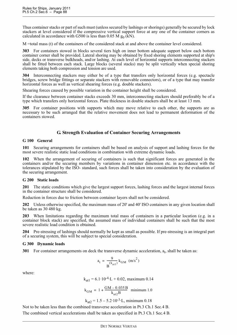
Rules for Ships, January 2011 Pt.5 Ch.2 Sec.6 – Page 88
Thus container stacks or part of such must (unless secured by lashings or shorings) generally be secured by lockstackers at level considered if the compressive vertical support force at any one of the container corners ascalculated in accordance with G500 is less than 0.05 M g0 (kN).
M =total mass (t) of the containers of the considered stack at and above the container level considered.303 For containers stowed in blocks several tiers high on inner bottom adequate support below each bottomcontainer corner shall be provided. Lateral shoring may be obtained by fixed shoring elements supported at ship'sside, decks or transverse bulkheads, and/or lashing. At each level of horizontal supports interconnecting stackersshall be fitted between each stack. Large blocks (several stacks) may be split vertically when special shoringelements taking both compression and tension are used.304 Interconnecting stackers may either be of a type that transfers only horizontal forces (e.g. spectaclebridges, screw bridge fittings or separate stackers with removable connectors), or of a type that may transferhorizontal forces as well as vertical shearing forces (e.g. double stackers).Shearing forces caused by possible variation in the container height shall be considered.If the clearance between container stacks exceeds 30 mm, interconnecting stackers should preferably be of atype which transfers only horizontal forces. Plate thickness in double stackers shall be at least 13 mm.305 For container positions with supports which may move relative to each other, the supports are asnecessary to be such arranged that the relative movement does not lead to permanent deformation of thecontainers stowed.
G. Strength Evaluation of Container Securing Arrangements
G 100 General101 Securing arrangements for containers shall be based on analysis of support and lashing forces for themost severe realistic static load conditions in combination with extreme dynamic loads.102 When the arrangement of securing of containers is such that significant forces are generated in thecontainers and/or the securing members by variations in container dimension etc. in accordance with thetolerances stipulated by the ISO- standard, such forces shall be taken into consideration by the evaluation ofthe securing arrangement.
G 200 Static loads201 The static conditions which give the largest support forces, lashing forces and the largest internal forcesin the container structure shall be considered.Reduction in forces due to friction between container layers shall not be considered.202 Unless otherwise specified, the maximum mass of 20' and 40' ISO containers in any given location shallbe taken as 30 480 kg.203 When limitations regarding the maximum total mass of containers in a particular location (e.g. in acontainer block stack) are specified, the assumed mass of individual containers shall be such that the mostsevere realistic load condition is obtained.204 Pre-stressing of lashings should normally be kept as small as possible. If pre-stressing is an integral partof a securing system, this will be subject to special consideration.
G 300 Dynamic loads301 For container arrangements on deck the transverse dynamic acceleration, at, shall be taken as:
where:kat1 = 6.1·10-4·L + 0.02, maximum 0.14
kat2 = 1.5 – 5.2·10-3·L, minimum 0.18Not to be taken less than the combined transverse acceleration in Pt.3 Ch.1 Sec.4 B.The combined vertical accelerations shall be taken as specified in Pt.3 Ch.1 Sec.4 B.
at9
Bkat1( )
---------------- kGM (m/s2 )=
kGM 1 GM 0.035 B–kat2B
---------------------------------- minimum 1.0+=
DET NORSKE VERITAS
Rules for Ships, January 2011 Pt.5 Ch.2 Sec.6 – Page 89
The combined longitudinal acceleration shall be taken as specified in Pt.3 Ch.1 Sec.4 B801, using half themaximum service speed (V/2). al shall not be taken less than 1.5 m/s2.302 For container arrangements below deck the transverse dynamic acceleration, at, shall be taken as:
where:
Not to be taken less than the combined transverse acceleration in Pt.3 Ch.1 Sec.4 B.The combined vertical accelerations shall be taken as specified in Pt.3 Ch.1 Sec.4 B.The combined longitudinal acceleration shall be taken as specified in Pt.3 Ch.1 Sec.4 B801, using half themaximum service speed (V/2). al shall not be taken less than 1.5 m/s2.303 As an option to 301 to 303 the results from a direct wave load analysis may be utilised after specialconsideration.
Guidance note:Such wave load analysis to be performed in accordance with CN 31.7 Ch.10. Normally, the North Atlantic wavescatter diagram should be used for determination of long term response. However, other wave scatter diagrams maybe used as per owner’s requirements.
---e-n-d---of---G-u-i-d-a-n-c-e---n-o-t-e---
304 All containers in a stack or a group of stacks are assumed to be subjected to the acceleration of gravityin combination with a uniform vertical acceleration according to 301 and 302.305 The containers in a stack or group of stacks are assumed to be subjected to transverse or longitudinalacceleration in accordance with 301 and 302.306 For non-rigid securing arrangements, acceleration loads according to 305 shall be combined with theacceleration of gravity acting downwards.307 Containers, the side walls of which will be exposed to wind (windward side only), shall be consideredfor a wind force Pw which for ISO standard containers may be taken as follows:
Pw = 18.5 kN for 20' containers= 37.0 kN for 40' containers= 7.5 kN for container ends.
308 For containers in positions which may be exposed to wind, the acceleration loads according to 305 shallbe combined with wind forces according to 307.
G 400 Strength analysis of rigid containment arrangements401 Cellular containment structures and containment arrangements with numerous sideway supports maynormally be considered as rigid containment arrangements.402 Normally, the racking stiffness of the containers may be disregarded in the analysis of the overallresponse of the containment structure. Deflections in the supporting structure should be taken into account.403 The analysis shall determine:
— nominal stresses in the containment structure— vertical and horizontal support forces— relevant internal forces in containers.
404 The calculation of stresses in cell guide structures and supporting structures for cell guide structures isin general to be based on the load cases LC4 and LC5 as given in C.
G 500 Strength analysis of non-rigid containment arrangements501 Securing arrangements including lashings and other flexible securing members or a small number ofrigid horizontal supports may normally be considered as non-rigid containment arrangements.502 The analysis shall take duly account of the flexibilities of containers and of the securing members as wellas possible deflections in the supporting structure.
at9
B0.23------------- kGM (m/s2 )=
kGM 1 GM 0.055 B–0.165B
---------------------------------- minimum 1.0+=
DET NORSKE VERITAS

Rules for Ships, January 2011 Pt.5 Ch.2 Sec.6 – Page 90
503 Possible effects of clearances between stacks of containers and between containers and supports shall betaken into account.
504 The analysis shall determine:
— vertical and horizontal support forces— forces in lashings and other securing members— internal forces in containers.
For further details, see Classification Note No. 32.2.
G 600 Support fittings
601 The strength of support fittings is generally to be analysed for maximum support forces as determinedunder 100 and 200.
602 The analysis shall include the support fitting with local supporting structures. It shall show the nominalmember capacities with respect to shear force, bending moment and axial force.
G 700 Acceptance criteria
701 Unless otherwise specified, calculated internal reaction forces in containers and external forces on thecontainer structure shall not exceed the tested minimum capabilities stated in the appropriate ISO-standard forfreight containers.Applicable container strength ratings according to this standard are given in Classification Note No. 32.2.
702 Maximum Securing Load in container securing devices shall not exceed:MSL = 0.5 Pm
Pm = minimum breaking load of considered equipment item.
Possible influence on the breaking load of fixed equipment by welding to the underlying structure shall be takeninto account.
703 Members of other materials subjected to tensile loads will be specially considered.
704 Nominal normal stresses in support fittings for containers and container lashings and other non-rigidcontainer securings (and in their local supporting structures) in hull structural steel, or as steel forgings orcastings shall not exceed:
σ = 210 f1 N/mm2.
705 Nominal shear stresses in support fittings for containers and container lashings and other non-rigidcontainer securings (and in their local supporting structures) in hull structural steel, or as steel forgings orcastings shall not exceed:
τ = 120 f1 N/mm2.
706 In supporting structures also subjected to longitudinal stresses (e.g. deck longitudinals and girders)combination with such stresses as given in Pt.3 Ch.1 Sec.8 is only to be performed for vertical container loads(rolling excluded). Allowable bending stresses may be increased by 30%.
707 Supporting structures subjected to compressive stresses shall be controlled for buckling in accordancewith Pt.3 Ch.1 Sec.14.
708 Corrosion additions for supporting members being part of hull structures (in tanks) shall be in accordancewith requirements given in Pt.3 Ch.1 Sec.2.
709 The compressive dynamic stress of cell guide structures is in general to be considered with respect to thelateral buckling mode according to Pt.3 Ch.1 Sec.14 C203 with k = 0.5.
H. Signboards
H 100 General
101 As far as found suitable for the ship in question, stowage and securing plans showing typical arrangementsand giving further reference to the “Stowage and Securing Manual” shall be posted at suitable locations in eachcargo space and in deck office.
DET NORSKE VERITAS
Rules for Ships, January 2011 Pt.5 Ch.2 Sec.6 – Page 91
I. Non-Weathertight Arrangement for Weather Deck Hatch CoversI 100 General101 For ships intended exclusively for the carriage of containers in cargo holds with non-weathertightarrangement of hatch covers in accordance with Pt.3 Ch.3 Sec.6 A, the requirements given under I shall becomplied with.102 A wave breaker shall be arranged for the protection of the forward non-weathertight hatch covers.Alternatively, the wave breaker may be omitted if the hatch covers forward of, or partly forward of, 0.15 L fromFP are weathertight.
Guidance note:The height of the wave breaker should normally be 5 m above the hatch cover top plate to cover two tiers of standardcontainers. A reduced height may be satisfactory in cases of large freeboard, i.e. when the top of the hatch cover plateis more than 3 standard superstructure heights (see ICLL Reg. 33) as calculated in K103.
---e-n-d---of---G-u-i-d-a-n-c-e---n-o-t-e---
103 Non-weathertight hatch covers may be fitted to hatchways located on weather decks, which shall be atleast two standard superstructure heights above an actual freeboard deck, or an assumed freeboard deck, fromwhich a freeboard can be calculated. The calculated freeboard shall result in a draught of not less than thatcorresponding to the actual freeboard assigned. Where any part of a hatchway is forward of a point located onequarter of the ship's length (0.25 L) from the forward perpendicular, then that hatchway shall be located on aweather deck, at least three standard superstructure heights above the actual or assumed freeboard deck. It shallbe understood that the assumed freeboard deck is used only for the purpose of measuring the height of the deckon which the hatchways are situated. The assumed freeboard deck may be an imaginary, or virtual deck andshall not be used for the actual assignment of the freeboard. The vessel's freeboard shall be assigned from anactual deck, designated as the freeboard deck, which shall be determined in accordance with the ICLL.104 The hatch coaming height shall not be less than 600 mm.105 The non-weathertight joints of hatch covers shall be designed to minimise the possible rate of wateringress by the arranging of labyrinths, gutter bars or equivalent.106 The containers in cargo holds with non-weathertight arrangement of hatch covers shall be positioned ondoubling plates or equivalent fitted on the inner bottom (or deck) with a height normally not less than 25 mm.
I 200 Bilge level alarms201 High water level alarms shall be installed for the bilge wells of container holds with non-weathertighthatch covers. The volume of each bilge well shall not be less than 1 m3.
I 300 Stability and damage stability301 Any non-weathertight joints of hatch covers shall be considered as unprotected openings with respect tothe requirements to stability and damage stability given in Pt.3 Ch.3 Sec.9.
Guidance note:Bilge pumping capacity: The bilge capacity of container holds with non-weathertight hatch covers may in general betaken as given in Pt.4 Ch.6. Dangerous goods: Facilities for carriage of dangerous goods may in general be arranged as for a vessel withweathertight hatches as given in Ch.11.Note that possible questions related to perishable cargo is outside the scope of classification.
---e-n-d---of---G-u-i-d-a-n-c-e---n-o-t-e---
DET NORSKE VERITAS
Rules for Ships, January 2011 Pt.5 Ch.2 Sec.7 – Page 92
SECTION 7 CAR CARRIERS
A. GeneralA 100 Classification101 The requirements in this section apply to ships intended for carriage of cars. 102 Ships built in compliance with relevant requirements for class notation General Cargo Carrier RO/RO (given in Sec.4) and built in compliance with relevant requirement specified in the following, will be giventhe class notation Car Carrier. 103 Ships arranged with movable car decks or deck pontoons shall be built in compliance with relevantrequirements in C and D.Such ships may be given the class notation MCDK.
A 200 Documentation201 For ships with movable car decks (MCDK) the following plans and particulars shall be submitted forinformation:
— maximum axle load including details of wheel and or foot print arrangement for all vehicles— uniform deck load— proposed procedure for function testing.
The following plans and particulars shall be submitted for approval:
— car deck pontoons and their weights— supports or suspensions — connections to hull structure with information regarding reaction forces from hoisting devices— stowing arrangement for deck pontoons not in use.
This should include all stressed strength members, such as racks on deck, securing devices, reinforcementof supporting hull structures, etc.
B. Hull StrengthB 100 General101 The relevant requirements given below shall be complied with.
B 200 Transverse strength201 Vessels with strength limited by transverse racking constraining structure shall be subject to a directstrength analysis to demonstrate that the stresses are acceptable in a heeled condition. Acceptable calculationmethods are given in Classification Note No. 31.2 “Strength analysis of hull structure in Roll on/Roll off shipsand Car Carriers”.202 The racking analyses shall be carried out for a realistic load distribution with maximum load carried onthe upper decks. The minimum GM for racking analysis shall be 0.05 B where B is the vessel’s width. 203 Car carriers may be designed for transverse strength secured by having self supporting side verticals. Asimplified racking assessment using beam models will then be accepted for documentation of the strength. 204 For vessels where the transverse strength is secured by a few heavy racking constraining structures andwhere the load distribution between these structural elements and the bow and the stern area is unknown, aglobal Finite Element Analysis shall be carried out to document the transverse strength.
B 300 Fatigue301 Structural details of racking constraining structure shall be specially considered to ensure a properresistance against fatigue. The Classification Note No. 31.2 “Strength analysis of hull structure in Roll on/Rolloff ships and Car Carriers” describes acceptable loads and procedures for such analyses.302 The loading condition (i.e. mass distribution) used for analysis of fatigue, shall have a GM not less than0.035 B.303 For ships of limited size (L < 150 m), the side verticals are usually designed as self supporting with
DET NORSKE VERITAS
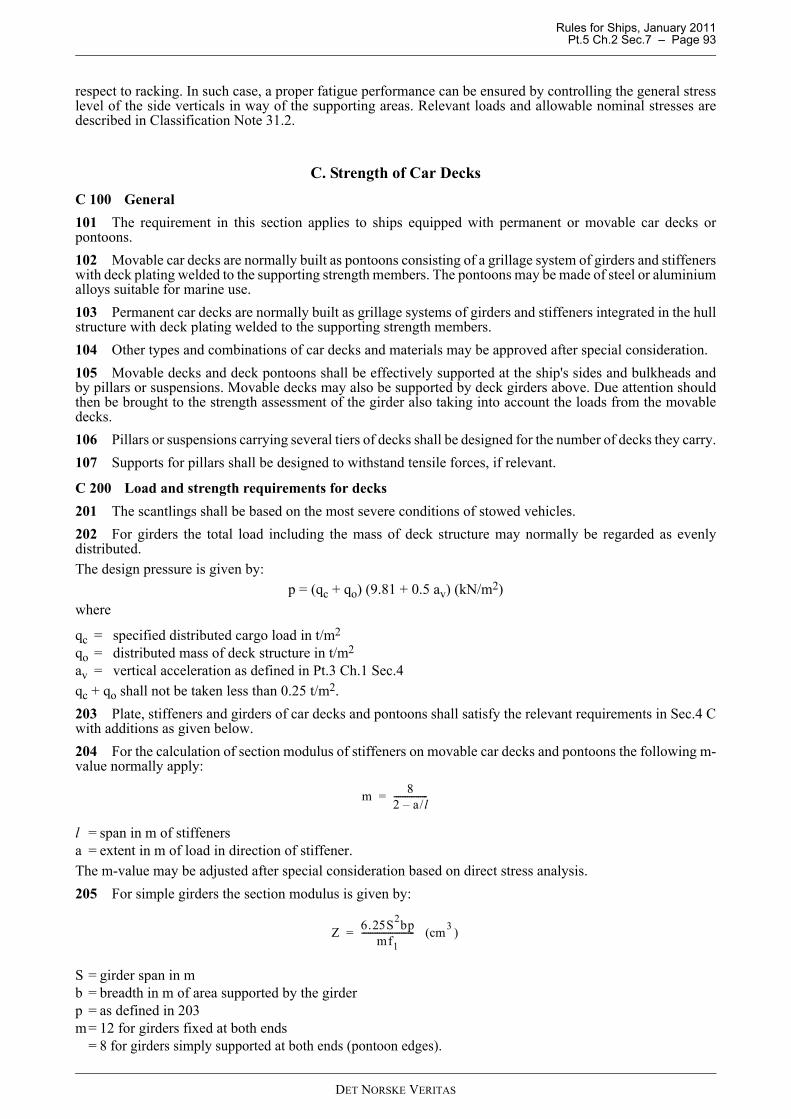
Rules for Ships, January 2011 Pt.5 Ch.2 Sec.7 – Page 93
respect to racking. In such case, a proper fatigue performance can be ensured by controlling the general stresslevel of the side verticals in way of the supporting areas. Relevant loads and allowable nominal stresses aredescribed in Classification Note 31.2.
C. Strength of Car Decks C 100 General101 The requirement in this section applies to ships equipped with permanent or movable car decks orpontoons. 102 Movable car decks are normally built as pontoons consisting of a grillage system of girders and stiffenerswith deck plating welded to the supporting strength members. The pontoons may be made of steel or aluminiumalloys suitable for marine use.103 Permanent car decks are normally built as grillage systems of girders and stiffeners integrated in the hullstructure with deck plating welded to the supporting strength members. 104 Other types and combinations of car decks and materials may be approved after special consideration.105 Movable decks and deck pontoons shall be effectively supported at the ship's sides and bulkheads andby pillars or suspensions. Movable decks may also be supported by deck girders above. Due attention shouldthen be brought to the strength assessment of the girder also taking into account the loads from the movabledecks.106 Pillars or suspensions carrying several tiers of decks shall be designed for the number of decks they carry.107 Supports for pillars shall be designed to withstand tensile forces, if relevant.
C 200 Load and strength requirements for decks201 The scantlings shall be based on the most severe conditions of stowed vehicles.202 For girders the total load including the mass of deck structure may normally be regarded as evenlydistributed. The design pressure is given by:
p = (qc + qo) (9.81 + 0.5 av) (kN/m2)where
qc = specified distributed cargo load in t/m2
qo = distributed mass of deck structure in t/m2
av = vertical acceleration as defined in Pt.3 Ch.1 Sec.4qc + qo shall not be taken less than 0.25 t/m2.203 Plate, stiffeners and girders of car decks and pontoons shall satisfy the relevant requirements in Sec.4 Cwith additions as given below.204 For the calculation of section modulus of stiffeners on movable car decks and pontoons the following m-value normally apply:
l = span in m of stiffenersa = extent in m of load in direction of stiffener.The m-value may be adjusted after special consideration based on direct stress analysis.205 For simple girders the section modulus is given by:
S = girder span in mb = breadth in m of area supported by the girderp = as defined in 203m= 12 for girders fixed at both ends = 8 for girders simply supported at both ends (pontoon edges).
m 82 a/l–---------------=
Z 6.25S2bpmf1
------------------------ (cm3 )=
DET NORSKE VERITAS

Rules for Ships, January 2011 Pt.5 Ch.2 Sec.7 – Page 94
For effective plate flange, see Pt.3 Ch.1 Sec.3 C.
206 The web area requirement (after deduction of cut-outs) at the girder end is given by:
The web area at the middle of the span shall not be less than 0.5 A.
207 For complex girder systems and or loads not being evenly distributed, the scantlings shall be based ondirect stress analysis.Allowable stresses are:
normal stress: σ= 160 f1 N/mm2
shear stress: τ = 90 f1 N/mm2.
208 Girders shall have a moment of inertia not less than:
I = C1 Z f1 S (cm4)where
C1 = 1.1 for steelC1 = 3.0 for aluminium alloyZ = section modulus of the girder in cm3
S = girder span in m.
209 The critical buckling stress of plating acting as girder flange shall not be less than:
σa = calculated compressive design stress.Tripping brackets and local stiffening of plating shall be provided where necessary.
C 300 Load and strength requirements for support and suspension
301 For calculation of supports and suspensions the total load on the movable deck or pontoon including theself mass shall be considered. The design load shall be as for the girders (i.e. uniform deck load).
302 The scantlings shall be based on direct stress analysis.
303 Allowable nominal stresses in support elements are:
— normal stress (tensile, compressive):σ = 110 f1 N/mm2
— shear stress:τ = 65 f1 N/mm2
— equivalent stress σe = 120 f1 N/mm2
304 Due attention shall be given to the local stress concentrations.
305 If slender supports are loaded in compression, it may be necessary to consider the allowable stressspecially.
306 For wire suspensions the minimum breaking load shall not be less than:Pm = 4 Pa (kN)
Pa = calculated design force in kN of wire.The construction and testing of steel wire suspensions shall comply with the requirements given in Pt.3 Ch.3Sec.3 for towlines and mooring lines.
A 0.06Sbpf1
--------------------- (cm2 )=
σcσa
0.87----------- (N/mm2 )=
σ2 3τ2+( )
DET NORSKE VERITAS
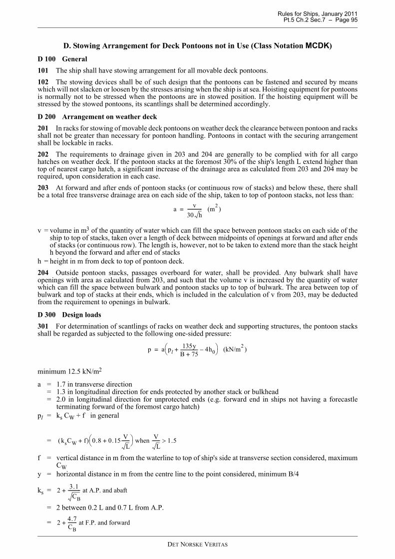
Rules for Ships, January 2011 Pt.5 Ch.2 Sec.7 – Page 95
D. Stowing Arrangement for Deck Pontoons not in Use (Class Notation MCDK)D 100 General101 The ship shall have stowing arrangement for all movable deck pontoons.102 The stowing devices shall be of such design that the pontoons can be fastened and secured by meanswhich will not slacken or loosen by the stresses arising when the ship is at sea. Hoisting equipment for pontoonsis normally not to be stressed when the pontoons are in stowed position. If the hoisting equipment will bestressed by the stowed pontoons, its scantlings shall be determined accordingly.
D 200 Arrangement on weather deck201 In racks for stowing of movable deck pontoons on weather deck the clearance between pontoon and racksshall not be greater than necessary for pontoon handling. Pontoons in contact with the securing arrangementshall be lockable in racks.202 The requirements to drainage given in 203 and 204 are generally to be complied with for all cargohatches on weather deck. If the pontoon stacks at the foremost 30% of the ship's length L extend higher thantop of nearest cargo hatch, a significant increase of the drainage area as calculated from 203 and 204 may berequired, upon consideration in each case.203 At forward and after ends of pontoon stacks (or continuous row of stacks) and below these, there shallbe a total free transverse drainage area on each side of the ship, taken to top of pontoon stacks, not less than:
v = volume in m3 of the quantity of water which can fill the space between pontoon stacks on each side of theship to top of stacks, taken over a length of deck between midpoints of openings at forward and after endsof stacks (or continuous row). The length is, however, not to be taken to extend more than the stack heighth beyond the forward and after end of stacks
h = height in m from deck to top of pontoon deck.204 Outside pontoon stacks, passages overboard for water, shall be provided. Any bulwark shall haveopenings with area as calculated from 203, and such that the volume v is increased by the quantity of waterwhich can fill the space between bulwark and pontoon stacks up to top of bulwark. The area between top ofbulwark and top of stacks at their ends, which is included in the calculation of v from 203, may be deductedfrom the requirement to openings in bulwark.
D 300 Design loads301 For determination of scantlings of racks on weather deck and supporting structures, the pontoon stacksshall be regarded as subjected to the following one-sided pressure:
minimum 12.5 kN/m2
a = 1.7 in transverse direction= 1.3 in longitudinal direction for ends protected by another stack or bulkhead= 2.0 in longitudinal direction for unprotected ends (e.g. forward end in ships not having a forecastle
terminating forward of the foremost cargo hatch)pl = ks CW + f in general
=
f = vertical distance in m from the waterline to top of ship's side at transverse section considered, maximumCW
y = horizontal distance in m from the centre line to the point considered, minimum B/4
ks =
= 2 between 0.2 L and 0.7 L from A.P.
=
a v30 h------------- (m2 )=
p a pl135y
B 75+---------------- 4h0–+⎝ ⎠
⎛ ⎞ (kN/m2 )=
ksCW f+( ) 0.8 0.15 VL
-------+⎝ ⎠⎛ ⎞ when V
L------- 1.5>
2 3.1CB
----------- at A.P. and abaft+
2 4.7CB-------- at F.P. and forward+
DET NORSKE VERITAS
Rules for Ships, January 2011 Pt.5 Ch.2 Sec.7 – Page 96
CW = wave coefficient as given in Pt.3 Ch.1 Sec.4.Between specified areas ks shall be varied linearly.Transverse and longitudinal pressures need not be considered as acting simultaneously.302 For pontoons stowed under deck, stowing and securing devices shall be designed for:
— transverse force not less than 5Q kN— vertical force not less than 13Q kN— longitudinal force not less than 2.5 kN.
Q = total load in t of pertinent stowed pontoons.
D 400 Allowable stresses401 Calculated, nominal combined stresses in stowing devices and their connections to supporting structuresshall not exceed 120 f1 N/mm2.402 Strength members subjected to buckling loads, shall have a safety factor against buckling not less than1.7.
DET NORSKE VERITAS
Rules for Ships, January 2011 Pt.5 Ch.2 Sec.8 – Page 97
SECTION 8 ENHANCED STRENGTH FOR BULK CARRIERS
A. Additional Requirements for Loading Conditions, Loading Manuals and Loading Instruments for Bulk Carriers, Ore Carriers and Combination Carriers
A 100 Application101 The requirements in this section shall be complied with by vessels as defined in Sec.5 A.
A 200 Loading manual201 The loading manual shall describe the following:
a) The loading conditions on which the design of the ship has been based, including permissible limits of stillwater bending moments and shear forces.
b) The results of calculations of still water bending moments, shear forces and where applicable, limitationsdue to torsional loads.
c) Envelope results and permissible limits to still water bending moments and shear forces in the hold floodedconditions are also to be included. See C200.
d) The cargo hold(s) or combination of holds that might be empty at full draught. If no cargo hold is allowedto be empty on full draught, this shall be clearly stated in the loading manual.
e) Maximum allowable and minimum required mass of cargo and double bottom contents of each hold as afunction of the draught at mid-hold position.
f) Maximum allowable and minimum required mass of cargo and double bottom contents of any two adjacentholds as a function of mean draught in way of these holds. This mean draught may be calculated byaveraging the draught of the two mid-hold positions.
g) Maximum allowable load on tank top together with specification of the nature of the cargo for cargoes otherthan bulk cargoes.
h) Maximum allowable load on deck and hatch covers. If the vessel is not approved to carry load on deck orhatch covers, this shall be clearly stated in the loading manual.
i) The maximum rate of ballast change together with the advice that a load plan shall be agreed with theterminal on the basis of achievable rates of change of ballast.
(IACS UR S1A.2.1, Rev. 5)
A 300 Loading instrument301 The Loading computer system shall be an approved digital system as given in Pt.3 Ch.1 Sec.5 and Pt.6Ch.9. The Loading computer system is, in addition to requirements given in Pt.3 Ch.1 Sec.5 A202, to ascertainas applicable that:
— the mass of cargo and double bottom contents in way of each hold as a function of the draught at mid-holdposition
— the mass of cargo and double bottom contents of any two adjacent holds as a function of the mean draughtin way of these holds
— the still water bending moments and shear forces in the hold flooded conditions are within permissiblevalues.
(IACS UR S1A.2.2, Rev. 5)
A 400 Conditions of approval of loading manuals401 The loading manual is, in addition to the requirements as given in Sec.5 A107 to 110 and A112 to 113and Pt.3 Ch.1 Sec.5 F200, to include the following loading conditions, subdivided into departure and arrival:
a) Alternate light and heavy cargo loading conditions at maximum draught, where applicable.b) Homogeneous light and heavy cargo loading conditions at maximum draught.c) Ballast conditions. For vessels having ballast holds adjacent to topside wing, hopper and double bottom
tanks, it shall be strengthwise acceptable that the ballast holds are filled when the topside wing, hopper anddouble bottom tanks are empty.
d) Short voyage conditions where the vessel shall be loaded to maximum draught but with limited amount ofbunkers.
DET NORSKE VERITAS
Rules for Ships, January 2011 Pt.5 Ch.2 Sec.8 – Page 98
e) Multiple port loading and unloading conditions.f) Deck cargo conditions, where applicable.g) Typical loading sequences where the vessel is loaded from commencement of cargo loading to reaching full
deadweight capacity, for homogeneous conditions, relevant part load conditions and alternate conditionswhere applicable.Typical unloading sequences for these conditions shall also be included. The typical loading and unloadingsequences shall be developed to not exceed applicable strength limitations. The typical loading sequencesshall also be developed paying due attention to the loading rate, and the de-ballasting capability.
h) Typical sequences for change of ballast at sea, where applicable.(IACS UR S1A.3, Rev. 5)Guidance note:The above listed loading conditions should be considered as mandatory for all vessels as applicable. I.e. loadingconditions, which are not applicable or not intended to be used, need not be considered in the design. Furthermore, the specification of e.g. short voyage and multiple port conditions are in general subject to agreementbetween owner and builder. This relates to the specification of the design loading conditions, which should take intoconsideration the intended modes and areas of operation. A short voyage condition may be a homogeneous or analternate condition where the cargo deadweight is increased with approximately 50% of the bunker weight.However, if some or all of the above conditions are not included in the Loading Manual a note to this effect shall begiven in the Loading Manual.
---e-n-d---of---G-u-i-d-a-n-c-e---n-o-t-e---
A 500 Condition of approval of loading instrument501 The loading instrument is subject to approval. The approval of loading instrument shall include asapplicable:
— acceptance of hull girder bending moments limits for all read-out points— acceptance of hull girder shear force limits for all read-out points— acceptance of limits for mass of cargo and double bottom contents of each hold as a function of draught— acceptance of limits for mass of cargo and double bottom contents in any two adjacent holds as a function
of draught— acceptance of shear force corrections.
(IACS UR S1A.4, Rev. 5)
B. Side StructureB 100 Application101 These requirements apply to side structure of cargo holds of single side construction.
B 200 Plating and stiffeners201 Thickness and cross section properties are in general to be calculated as given in Pt.3 Ch.1 Sec.7.202 The minimum thickness of side plating, located between hopper and top wing tanks and extending inlength over the whole cargo area, shall not be less than:
when L is as defined in Pt.3 Ch.1 Sec.1 B.(IACS UR S12.8, Rev. 4)
t L=
DET NORSKE VERITAS
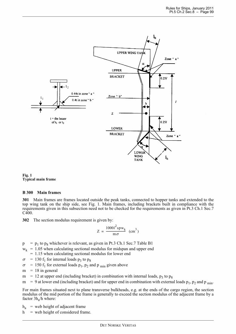
Rules for Ships, January 2011 Pt.5 Ch.2 Sec.8 – Page 99
Fig. 1Typical main frame
B 300 Main frames
301 Main frames are frames located outside the peak tanks, connected to hopper tanks and extended to thetop wing tank on the ship side, see Fig. 1. Main frames, including brackets built in compliance with therequirements given in this subsection need not to be checked for the requirements as given in Pt.3 Ch.1 Sec.7C400.
302 The section modulus requirement is given by:
p = p1 to p8 whichever is relevant, as given in Pt.3 Ch.1 Sec.7 Table B1wk = 1.05 when calculating sectional modulus for midspan and upper end
= 1.15 when calculating sectional modulus for lower endσ = 130 f1 for internal loads p3 to p8σ = 150 f1 for external loads p1, p2 and p min given abovem = 18 in generalm = 12 at upper end (including bracket) in combination with internal loads, p3 to p8m = 9 at lower end (including bracket) and for upper end in combination with external loads p1, p2 and p min.
For main frames situated next to plane transverse bulkheads, e.g. at the ends of the cargo region, the sectionmodulus of the mid portion of the frame is generally to exceed the section modulus of the adjacent frame by afactor 3ha/h where:
ha = web height of adjacent frameh = web height of considered frame.
Z1000l2spwk
mσ------------------------------ (cm3 )=
DET NORSKE VERITAS
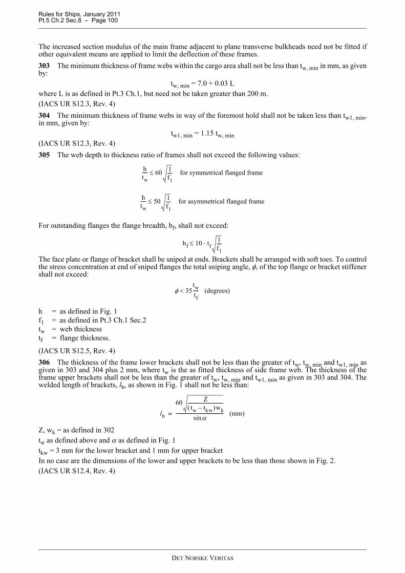
Rules for Ships, January 2011 Pt.5 Ch.2 Sec.8 – Page 100
The increased section modulus of the main frame adjacent to plane transverse bulkheads need not be fitted ifother equivalent means are applied to limit the deflection of these frames.303 The minimum thickness of frame webs within the cargo area shall not be less than tw, min in mm, as givenby:
tw, min = 7.0 + 0.03 Lwhere L is as defined in Pt.3 Ch.1, but need not be taken greater than 200 m.(IACS UR S12.3, Rev. 4)304 The minimum thickness of frame webs in way of the foremost hold shall not be taken less than tw1, min,in mm, given by:
tw1, min = 1.15 tw, min(IACS UR S12.3, Rev. 4)305 The web depth to thickness ratio of frames shall not exceed the following values:
For outstanding flanges the flange breadth, bf, shall not exceed:
The face plate or flange of bracket shall be sniped at ends. Brackets shall be arranged with soft toes. To controlthe stress concentration at end of sniped flanges the total sniping angle, φ, of the top flange or bracket stiffenershall not exceed:
h = as defined in Fig. 1f1 = as defined in Pt.3 Ch.1 Sec.2tw = web thicknesstf = flange thickness.
(IACS UR S12.5, Rev. 4)306 The thickness of the frame lower brackets shall not be less than the greater of tw, tw, min and tw1, min asgiven in 303 and 304 plus 2 mm, where tw is the as fitted thickness of side frame web. The thickness of theframe upper brackets shall not be less than the greater of tw, tw, min and tw1, min as given in 303 and 304. Thewelded length of brackets, lb, as shown in Fig. 1 shall not be less than:
Z, wk = as defined in 302tw as defined above and α as defined in Fig. 1tkw = 3 mm for the lower bracket and 1 mm for upper bracketIn no case are the dimensions of the lower and upper brackets to be less than those shown in Fig. 2.(IACS UR S12.4, Rev. 4)
htw----- 60 1
f1---- for symmetrical flanged frame≤
htw----- 50 1
f1---- for asymmetrical flanged frame≤
bf 10 tf1f1----⋅≤
φ 35twtf----- (degrees)<
lb
60 Ztw tkw–( )wk
-------------------------------
αsin------------------------------------------ (mm)=
DET NORSKE VERITAS
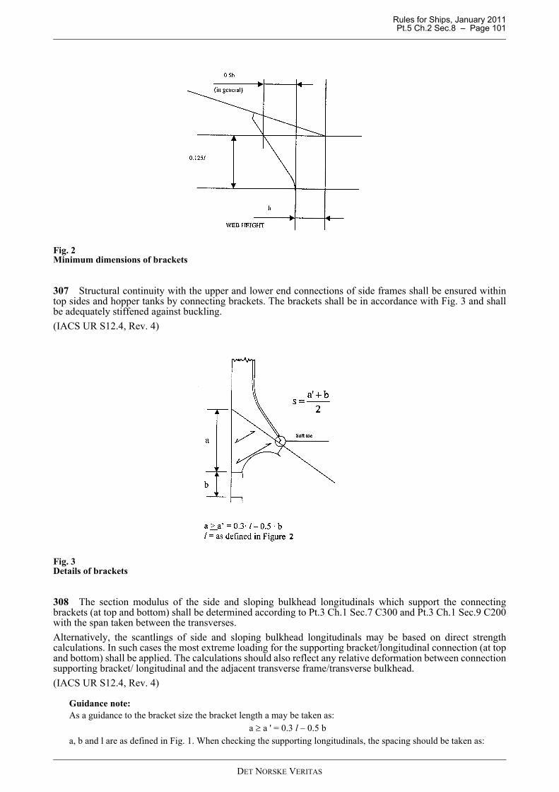
Rules for Ships, January 2011 Pt.5 Ch.2 Sec.8 – Page 101
Fig. 2Minimum dimensions of brackets
307 Structural continuity with the upper and lower end connections of side frames shall be ensured withintop sides and hopper tanks by connecting brackets. The brackets shall be in accordance with Fig. 3 and shallbe adequately stiffened against buckling.(IACS UR S12.4, Rev. 4)
Fig. 3Details of brackets
308 The section modulus of the side and sloping bulkhead longitudinals which support the connectingbrackets (at top and bottom) shall be determined according to Pt.3 Ch.1 Sec.7 C300 and Pt.3 Ch.1 Sec.9 C200with the span taken between the transverses.Alternatively, the scantlings of side and sloping bulkhead longitudinals may be based on direct strengthcalculations. In such cases the most extreme loading for the supporting bracket/longitudinal connection (at topand bottom) shall be applied. The calculations should also reflect any relative deformation between connectionsupporting bracket/ longitudinal and the adjacent transverse frame/transverse bulkhead.(IACS UR S12.4, Rev. 4)
Guidance note:As a guidance to the bracket size the bracket length a may be taken as:
a ≥ a ' = 0.3 l – 0.5 ba, b and l are as defined in Fig. 1. When checking the supporting longitudinals, the spacing should be taken as:
DET NORSKE VERITAS
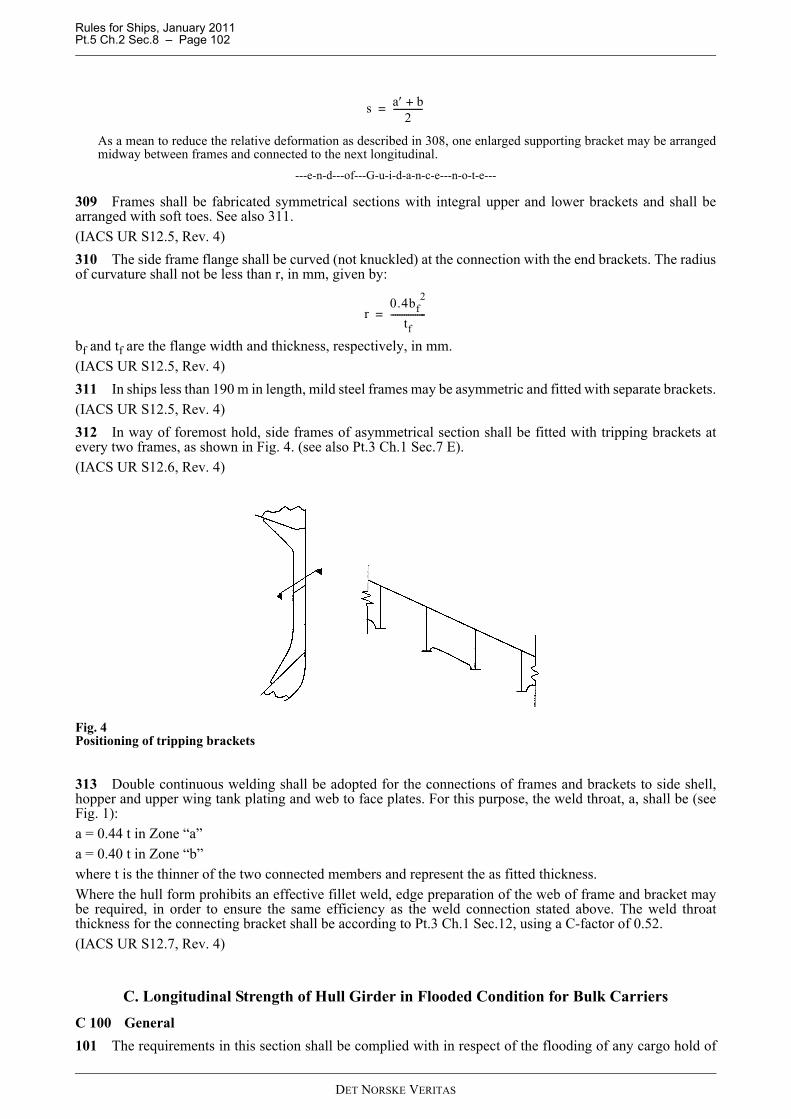
Rules for Ships, January 2011 Pt.5 Ch.2 Sec.8 – Page 102
As a mean to reduce the relative deformation as described in 308, one enlarged supporting bracket may be arrangedmidway between frames and connected to the next longitudinal.
---e-n-d---of---G-u-i-d-a-n-c-e---n-o-t-e---
309 Frames shall be fabricated symmetrical sections with integral upper and lower brackets and shall bearranged with soft toes. See also 311.(IACS UR S12.5, Rev. 4)310 The side frame flange shall be curved (not knuckled) at the connection with the end brackets. The radiusof curvature shall not be less than r, in mm, given by:
bf and tf are the flange width and thickness, respectively, in mm.(IACS UR S12.5, Rev. 4)311 In ships less than 190 m in length, mild steel frames may be asymmetric and fitted with separate brackets.(IACS UR S12.5, Rev. 4)312 In way of foremost hold, side frames of asymmetrical section shall be fitted with tripping brackets atevery two frames, as shown in Fig. 4. (see also Pt.3 Ch.1 Sec.7 E).(IACS UR S12.6, Rev. 4)
Fig. 4Positioning of tripping brackets
313 Double continuous welding shall be adopted for the connections of frames and brackets to side shell,hopper and upper wing tank plating and web to face plates. For this purpose, the weld throat, a, shall be (seeFig. 1):a = 0.44 t in Zone “a”a = 0.40 t in Zone “b”where t is the thinner of the two connected members and represent the as fitted thickness.Where the hull form prohibits an effective fillet weld, edge preparation of the web of frame and bracket maybe required, in order to ensure the same efficiency as the weld connection stated above. The weld throatthickness for the connecting bracket shall be according to Pt.3 Ch.1 Sec.12, using a C-factor of 0.52.(IACS UR S12.7, Rev. 4)
C. Longitudinal Strength of Hull Girder in Flooded Condition for Bulk CarriersC 100 General101 The requirements in this section shall be complied with in respect of the flooding of any cargo hold of
s a′ b+2
-------------=
r0.4bf
2
tf----------------=
DET NORSKE VERITAS

Rules for Ships, January 2011 Pt.5 Ch.2 Sec.8 – Page 103
bulk carriers with BC-A or BC-B class notation, as given in Sec.5 A.The hull girder strength shall be checked for specified flooded conditions in each of the cargo and ballastloading conditions given in Pt.3 Ch.1 Sec.5 B and in every other condition considered in the intact longitudinalstrength calculations, including those given in Sec.8 A, except that harbour conditions, docking conditionafloat, loading and unloading transitory conditions in port and loading conditions encountered during ballastwater exchange need not to be considered.(IACS UR S17.1, Rev. 7)
C 200 Flooded conditions201 Each cargo hold shall be considered individually flooded to the equilibrium waterline. The still water loads in flooded conditions shall be calculated for cargo and ballast loading conditions as givenin 101.The wave loads in the flooded conditions are assumed to be equal to 80% of those given in Pt.3 Ch.1 Sec.5 B.(IACS UR S17.2, Rev. 7)
C 300 Flooding criteria301 To calculate the mass of water ingress, the following assumptions shall be made:
— The permeability of empty cargo spaces and volume left in loaded cargo spaces above any cargo shall betaken as 0.95.
— Appropriate permeabilities and bulk densities shall be used for any cargo carried. For iron ore, a minimumpermeability of 0.3 with a corresponding bulk density of 3.0 t/m3 shall be used. For cement, a minimumpermeability of 0.3 with a corresponding bulk density of 1.3 t/m3 shall be used. In this respect,“permeability” for solid bulk cargo means the ratio of the floodable volume between the particles, granulesor any larger pieces of the cargo, to the gross volume of the bulk cargo.
For packed cargo conditions (such as steel mill products), the actual density of the cargo should be used witha permeability of zero.(IACS UR S17.3, Rev. 7)
Guidance note:In order to check the longitudinal strength in flooded condition a permeability of 0.3 is considered generallyacceptable also for light cargoes.
---e-n-d---of---G-u-i-d-a-n-c-e---n-o-t-e---
C 400 Stress assessment401 The actual hull girder bending stress σfld, in N/mm2, at any location is given by:
where:
M sf = still water bending moment, in kNm, in the flooded conditions for the section under considerationMw = wave bending moment as given in Pt.3 Ch.1 Sec.5 BZz = section modulus, in cm3, for the corresponding location in the hull girder.σfld ≤ 175 f1 N/mm2 within the cargo area.
The shear strength of the side shell and the inner hull (longitudinal bulkhead) if any, shall at any location of thevessel be checked according to the requirements given in Pt.3 Ch.1 Sec.5 D in which QS and QW shall bereplaced by Qsf and Qwf respectively, where:
Qsf = still water shear force, in kN, in the flooded conditions for the section under considerationQwf = 0.8QWQW = wave shear force, in kN, as given in Pt.3 Ch.1 Sec.5 B203 for the section under consideration
τfld ≤ 110 f1 N/mm2.(IACS UR S17.4, Rev. 7)402 The damaged structure is assumed to remain fully effective in resisting the applied loading.Uniaxial buckling capacity shall be checked according to Pt.3 Ch.1 Sec.13.(IACS UR S17.5, Rev. 7)
σfldMsf 0.8Mw+
Zz--------------------------------- 103
=
DET NORSKE VERITAS
Rules for Ships, January 2011 Pt.5 Ch.2 Sec.8 – Page 104
D. Corrugated Transverse Watertight Bulkheads, Considering Hold FloodingD 100 Application and definition101 These requirements apply to vertically corrugated transverse watertight bulkheads. The requirements inthis section shall be complied with in respect to the flooding of any cargo hold of bulk carriers, as defined bySec.5A.The net thickness tnet is the thickness obtained by applying the strength criteria as given in 300 to 308.The required thickness is obtained by adding the corrosion addition ts, given in 500, to the net thickness tnet.In this requirement, homogeneous loading condition means a loading condition in which the ratio between thehighest and the lowest filling ratio, evaluated for each hold, does not exceed 1.2 (corrected for different cargodensities).For non-corrugated bulkheads, scantlings for plates, stiffeners and girders shall not be less than required in Pt.3Ch.1 Sec.9, applying the pressure loads as given in 201 to 207.Vertically corrugated bulkheads built in compliance with the requirements given in this subsection need not tobe checked for the requirements relating to watertight bulkhead loads given in Pt.3 Ch.1 Sec.9.(IACS UR S18.1, Rev. 7)
D 200 Load model201 GeneralThe loads to be considered as acting on the bulkheads are those given by the combination of the cargo loadswith those induced by the flooding of one hold adjacent to the bulkhead under examination. In any case, thepressure due to the flooding water alone shall be considered. The most severe combinations of cargo inducedloads and flooding loads shall be used for the check of the scantlings of each bulkhead, depending on theloading conditions included in the loading manual:
— homogeneous loading conditions— non-homogeneous loading conditions
considering the individual flooding of both loaded and empty holds.The specified design load limits for the cargo holds shall be represented by loading conditions defined by thedesigner in the loading manual.Non-homogeneous part loading conditions associated with multi port loading and unloading operations forhomogeneous loading conditions need not be considered according to these requirements.Holds carrying packed cargoes shall be considered as empty holds for this application.Unless the ship is intended to carry, in non-homogeneous conditions, only iron ore or cargo having bulk densityequal or greater than 1.78 t/m3, the maximum mass of cargo which may be carried in the hold is also to beconsidered to fill that hold up to the upper deck level at centreline.(IACS UR S18.2.1, Rev. 7)
Guidance note:Bulk Carriers as defined in Sec.5 A100 without class notation BC-A and BC-B*, and only to be homogeneouslyloaded as defined in 101, may have their bulkheads checked for homogeneous loading and flooding water alone only,provided this limitation is explicitly stated in the ship's Loading Manual.
---e-n-d---of---G-u-i-d-a-n-c-e---n-o-t-e---
202 Bulkhead corrugation flooding headThe flooding head hf (see Fig. 5) is the distance, in m, measured vertically with the ship in the upright position,from the calculation point to a level located at a distance df, in m, from the baseline equal to:a) in general:
− D for the foremost transverse corrugated bulkhead− 0.9 D for the other bulkheads.Where the ship shall carry cargoes having bulk density less than 1.78 t/m3 in non-homogeneous loadingconditions, the following values can be assumed:
− 0.95 D for the foremost transverse corrugated bulkhead− 0.85 D for the other bulkheads.b) for ships less than 50 000 tonnes deadweight with Type B freeboard:
− 0.95 D for the foremost transverse corrugated bulkhead− 0.85 D for the other bulkheads.
DET NORSKE VERITAS

Rules for Ships, January 2011 Pt.5 Ch.2 Sec.8 – Page 105
Where the ship shall carry cargoes having bulk density less than 1.78 t/m3 in non-homogeneous loadingconditions, the following values can be assumed:
− 0.9 D for the foremost transverse corrugated bulkhead− 0.8 D for the other bulkheadsD is the distance, in m, from the baseline to the freeboard deck at side amidships (see Fig. 5).(IACS UR S18.2.2, Rev. 7)
Fig. 5Definition of D, h1and d1.
203 Pressure in non-flooded bulk cargo loaded holdsAt each point of the bulkhead, the pressure pc, in kN/m2, is given by:
pc = ρc g h1 K
ρc = bulk cargo density, in t/m3
g = 9.81 m/s2, gravity accelerationh1 = vertical distance, in m, from the calculation point to horizontal plane corresponding to the volume of the
cargo (see Fig. 5), located at a distance d1, in m, from the baselineK = sin2α · tan2(45 – 0.5δ) + cos2α
= cosα minimumα = angle between panel in question and the horizontal plane, in degreesδ = angle of repose of the cargo, in degrees, that may generally be taken as 35° for iron ore and 25° for
cement.
The force Fc, in kN, acting on a corrugation is given by:
ρc, g, d1, K = as given above
s1 = spacing of corrugations, in m (see Fig. 6)h LS = mean height of the lower stool, in m, from the inner bottomh DB = height of the double bottom, in m.
Fc ρcgs1d1 hDB– hLS–( )2
2--------------------------------------------K=
DET NORSKE VERITAS
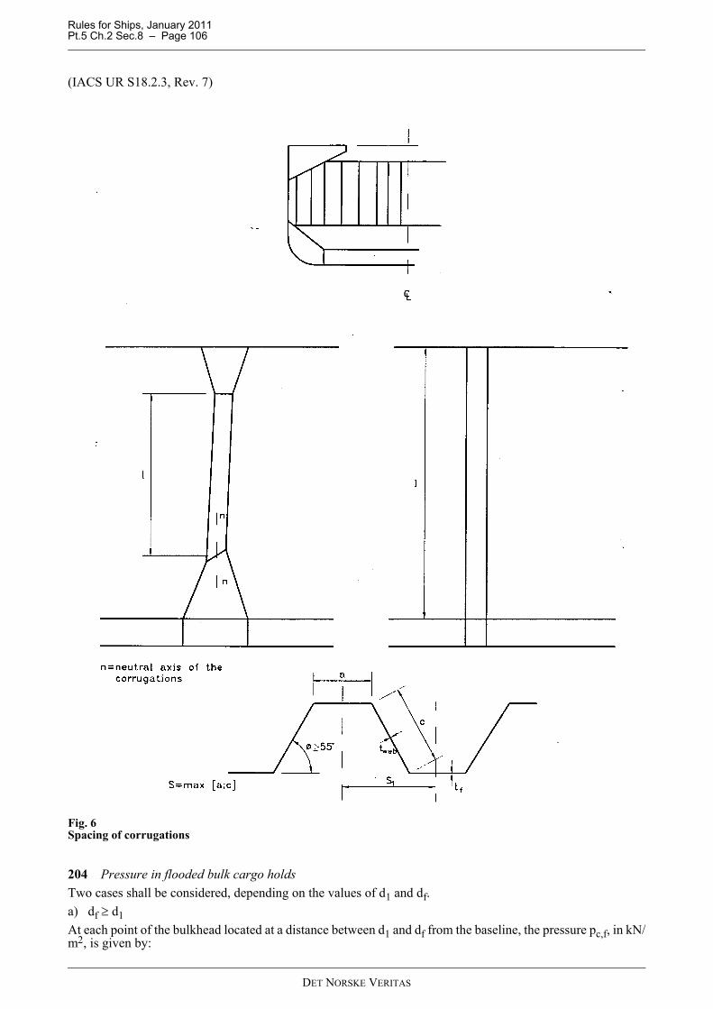
Rules for Ships, January 2011 Pt.5 Ch.2 Sec.8 – Page 106
(IACS UR S18.2.3, Rev. 7)
Fig. 6Spacing of corrugations
204 Pressure in flooded bulk cargo holdsTwo cases shall be considered, depending on the values of d1 and df.a) df ≥ d1At each point of the bulkhead located at a distance between d1 and df from the baseline, the pressure pc,f, in kN/m2, is given by:
DET NORSKE VERITAS
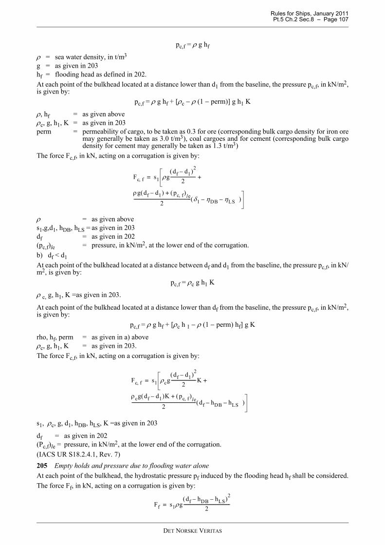
Rules for Ships, January 2011 Pt.5 Ch.2 Sec.8 – Page 107
pc,f = ρ g hf
ρ = sea water density, in t/m3
g = as given in 203hf = flooding head as defined in 202.At each point of the bulkhead located at a distance lower than d1 from the baseline, the pressure pc,f, in kN/m2,is given by:
pc,f = ρ g hf + [ρc − ρ (1 − perm)] g h1 K
ρ, hf = as given aboveρc, g, h1, K = as given in 203perm = permeability of cargo, to be taken as 0.3 for ore (corresponding bulk cargo density for iron ore
may generally be taken as 3.0 t/m3), coal cargoes and for cement (corresponding bulk cargodensity for cement may generally be taken as 1.3 t/m3)
The force Fc,f, in kN, acting on a corrugation is given by:
ρ = as given aboves1,g,d1, hDB, hLS = as given in 203df = as given in 202(pc,f)le = pressure, in kN/m2, at the lower end of the corrugation.b) df < d1At each point of the bulkhead located at a distance between df and d1 from the baseline, the pressure pc,f, in kN/m2, is given by:
pc,f = ρc g h1 K
ρ c, g, h1, K =as given in 203.
At each point of the bulkhead located at a distance lower than df from the baseline, the pressure pc,f, in kN/m2,is given by:
pc,f = ρ g hf + [ρc h 1 − ρ (1 − perm) hf] g K
rho, hf, perm = as given in a) aboveρc, g, h1, K = as given in 203.The force Fc,f, in kN, acting on a corrugation is given by:
s1, ρc, g, d1, hDB, hLS, K =as given in 203
df = as given in 202(Pc,f)le = pressure, in kN/m2, at the lower end of the corrugation.(IACS UR S18.2.4.1, Rev. 7)205 Empty holds and pressure due to flooding water aloneAt each point of the bulkhead, the hydrostatic pressure pf induced by the flooding head hf shall be considered.The force Ff, in kN, acting on a corrugation is given by:
Fc f, s1 ρgdf d1–( )2
2-----------------------
ρg df d1–( ) pc f,( )le+
2----------------------------------------------------- δ1 ηDB– ηLS –( )
+=
Fc f, s1 ρcgdf d1–( )2
2-----------------------K
ρcg df d1–( )K pc f,( )le+
2------------------------------------------------------------ df hDB– hLS –( )
+=
Ff s1ρgdf hDB– hLS–( )2
2-------------------------------------------=
DET NORSKE VERITAS
Rules for Ships, January 2011 Pt.5 Ch.2 Sec.8 – Page 108
s1, g, hDB, hLS = as given in 203ρ = as given in 204 a)df = as given in 202.(IACS UR S18.2.4.2, Rev. 7)206 Resultant pressure and force - Homogeneous loading conditionsAt each point of the bulkhead structures, the resultant pressure p, in kN/m2, to be considered for the scantlingsof the bulkhead is given by:
p = pc,f − 0.8 pcThe resultant force F, in kN, acting on a corrugation is given by:
F = Fc,f − 0.8 Fc(IACS UR S18.2.5.1, Rev. 7)207 Resultant pressure and force - Non-homogeneous loading conditionsAt each point of the bulkhead structures, the resultant pressure p, in kN/m2, to be considered for the scantlingsof the bulkhead is given by:
p = pc,fThe resultant force F, in kN, acting on a corrugation is given by:
F = Fc,f(IACS UR S18.2.5.2, Rev. 7)208 Bending moment in the bulkhead corrugationThe design bending moment M, in kNm, for the bulkhead corrugation is given by:
F = resultant force, in kN, as given in 205, 206 or 207 as relevantl = span of the corrugation, in m, to be taken according to Fig. 6 and Fig. 7.
(IACS UR S18.3.1, Rev. 7)
M Fl8-----=
DET NORSKE VERITAS
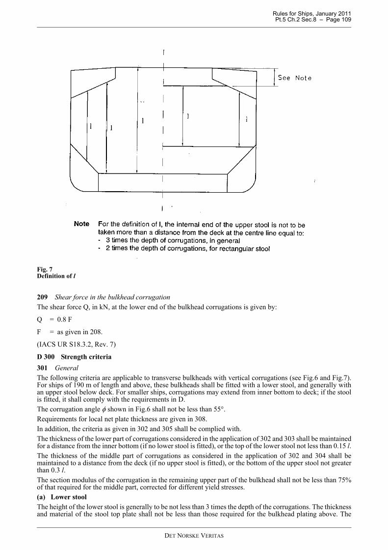
Rules for Ships, January 2011 Pt.5 Ch.2 Sec.8 – Page 109
Fig. 7Definition of l
209 Shear force in the bulkhead corrugationThe shear force Q, in kN, at the lower end of the bulkhead corrugations is given by:
Q = 0.8 F
F = as given in 208.
(IACS UR S18.3.2, Rev. 7)
D 300 Strength criteria301 GeneralThe following criteria are applicable to transverse bulkheads with vertical corrugations (see Fig.6 and Fig.7).For ships of 190 m of length and above, these bulkheads shall be fitted with a lower stool, and generally withan upper stool below deck. For smaller ships, corrugations may extend from inner bottom to deck; if the stoolis fitted, it shall comply with the requirements in D.The corrugation angle φ shown in Fig.6 shall not be less than 55°.Requirements for local net plate thickness are given in 308.In addition, the criteria as given in 302 and 305 shall be complied with.The thickness of the lower part of corrugations considered in the application of 302 and 303 shall be maintainedfor a distance from the inner bottom (if no lower stool is fitted), or the top of the lower stool not less than 0.15 l.The thickness of the middle part of corrugations as considered in the application of 302 and 304 shall bemaintained to a distance from the deck (if no upper stool is fitted), or the bottom of the upper stool not greaterthan 0.3 l.The section modulus of the corrugation in the remaining upper part of the bulkhead shall not be less than 75%of that required for the middle part, corrected for different yield stresses.(a) Lower stoolThe height of the lower stool is generally to be not less than 3 times the depth of the corrugations. The thicknessand material of the stool top plate shall not be less than those required for the bulkhead plating above. The
DET NORSKE VERITAS
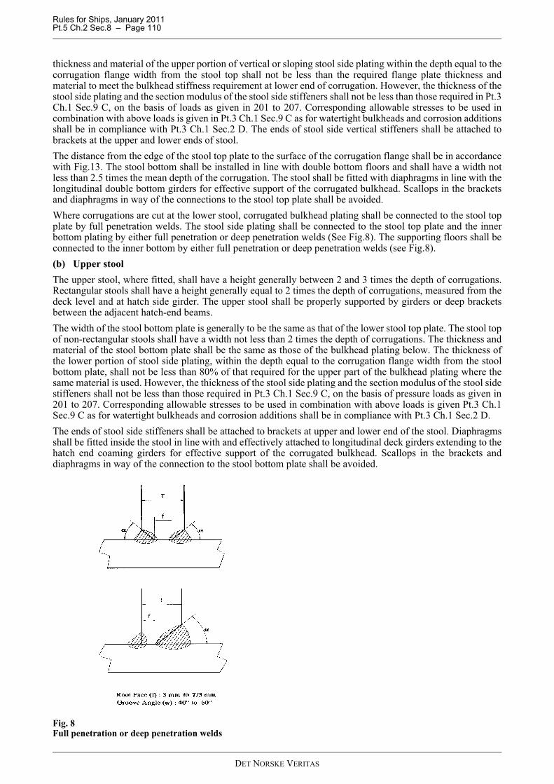
Rules for Ships, January 2011 Pt.5 Ch.2 Sec.8 – Page 110
thickness and material of the upper portion of vertical or sloping stool side plating within the depth equal to thecorrugation flange width from the stool top shall not be less than the required flange plate thickness andmaterial to meet the bulkhead stiffness requirement at lower end of corrugation. However, the thickness of thestool side plating and the section modulus of the stool side stiffeners shall not be less than those required in Pt.3Ch.1 Sec.9 C, on the basis of loads as given in 201 to 207. Corresponding allowable stresses to be used incombination with above loads is given in Pt.3 Ch.1 Sec.9 C as for watertight bulkheads and corrosion additionsshall be in compliance with Pt.3 Ch.1 Sec.2 D. The ends of stool side vertical stiffeners shall be attached tobrackets at the upper and lower ends of stool.The distance from the edge of the stool top plate to the surface of the corrugation flange shall be in accordancewith Fig.13. The stool bottom shall be installed in line with double bottom floors and shall have a width notless than 2.5 times the mean depth of the corrugation. The stool shall be fitted with diaphragms in line with thelongitudinal double bottom girders for effective support of the corrugated bulkhead. Scallops in the bracketsand diaphragms in way of the connections to the stool top plate shall be avoided.Where corrugations are cut at the lower stool, corrugated bulkhead plating shall be connected to the stool topplate by full penetration welds. The stool side plating shall be connected to the stool top plate and the innerbottom plating by either full penetration or deep penetration welds (See Fig.8). The supporting floors shall beconnected to the inner bottom by either full penetration or deep penetration welds (see Fig.8).(b) Upper stoolThe upper stool, where fitted, shall have a height generally between 2 and 3 times the depth of corrugations.Rectangular stools shall have a height generally equal to 2 times the depth of corrugations, measured from thedeck level and at hatch side girder. The upper stool shall be properly supported by girders or deep bracketsbetween the adjacent hatch-end beams.The width of the stool bottom plate is generally to be the same as that of the lower stool top plate. The stool topof non-rectangular stools shall have a width not less than 2 times the depth of corrugations. The thickness andmaterial of the stool bottom plate shall be the same as those of the bulkhead plating below. The thickness ofthe lower portion of stool side plating, within the depth equal to the corrugation flange width from the stoolbottom plate, shall not be less than 80% of that required for the upper part of the bulkhead plating where thesame material is used. However, the thickness of the stool side plating and the section modulus of the stool sidestiffeners shall not be less than those required in Pt.3 Ch.1 Sec.9 C, on the basis of pressure loads as given in201 to 207. Corresponding allowable stresses to be used in combination with above loads is given Pt.3 Ch.1Sec.9 C as for watertight bulkheads and corrosion additions shall be in compliance with Pt.3 Ch.1 Sec.2 D.The ends of stool side stiffeners shall be attached to brackets at upper and lower end of the stool. Diaphragmsshall be fitted inside the stool in line with and effectively attached to longitudinal deck girders extending to thehatch end coaming girders for effective support of the corrugated bulkhead. Scallops in the brackets anddiaphragms in way of the connection to the stool bottom plate shall be avoided.
Fig. 8Full penetration or deep penetration welds
DET NORSKE VERITAS
Rules for Ships, January 2011 Pt.5 Ch.2 Sec.8 – Page 111
(c) AlignmentAt deck, if no stool is fitted, two transverse reinforced beams shall be fitted in line with the corrugation flanges.At bottom, if no stool is fitted, the corrugation flanges shall be in line with the supporting floors. Corrugatedbulkhead plating shall be connected to the inner bottom plating by full penetration welds. The plating ofsupporting floors shall be connected to the inner bottom by either full penetration or deep penetration welds(see Fig.8). The thickness and material properties of the supporting floors shall be at least equal to those provided for thecorrugation flanges. Moreover, the cut-outs for connections of the inner bottom longitudinals to double bottomfloors shall be closed by collar plates. The supporting floors shall be connected to each other by suitablydesigned shear plates.Stool side plating shall align with the corrugation flanges and stool side vertical stiffeners and their brackets inlower stool shall align with the inner bottom longitudinals to provide appropriate load transmission betweenthese stiffening members. Stool side plating shall not be knuckled anywhere between the inner bottom platingand the stool top.(IACS UR S18.4.1, Rev. 7)302 Bending capacity and shear stress τThe bending capacity shall comply with the following relationship:
M = bending moment, in kNm, as given in 208Zle = section modulus, in cm3, at the lower end of corrugations, to be calculated according to 303Zm = section modulus, in cm3, at the midspan of corrugations, to be calculated according to 304σa,le = allowable stress, in N/mm2, as given in 305, for the lower end of corrugationsσa,m = allowable stress, in N/mm2, as given in 305, for the mid-span of corrugations.
In no case is Zm to be taken greater than the lesser of 1.15 Zle and 1.15 Z'le for calculation of the bendingcapacity, Z'le as being defined below.In case shedder plates are fitted which:
— are not knuckled— are welded to the corrugations and the top of the lower stool by one side penetration welds or equivalent— are fitted with a minimum slope of 45° and their lower edge is in line with the stool side plating— have thickness not less than 75% of that provided by the corrugation flanges— and material properties at least equal to those provided by the flanges
or gusset plates are fitted which:
— are in combination with shedder plates having thickness, material properties and welded connections inaccordance with the above requirements
— have a height not less than half of the flange width— are fitted in line with the stool side plating— are generally welded to the top of the lower stool by full penetration welds, and to the corrugations and
shedder plates by one side penetration welds or equivalent— have thickness and material properties at least equal to those provided for the flanges
the section modulus Zle, in cm3, shall be taken not larger than the value Z'le, in cm3, given by:
Zg = section modulus, in cm3, of the corrugations calculated, according to 304, in way of the upper end ofshedder or gusset plates, as applicable
Q = shear force, in kN, as given in 209hg = height, in m, of shedders or gusset plates, as applicable (see Fig.9, Fig.10, Fig.11 and Fig.12)s1 = as given in 203pg = resultant pressure, in kN/m2, as defined in 206 or 207 as relevant calculated in way of the middle of the
shedders or gusset plates, as applicableσa = allowable stress, in N/mm2, as given in 305.
Stresses, τ, are obtained by dividing the shear force, Q, by the shear area. The shear area shall be reduced inorder to account for possible non-perpendicularity between the corrugation webs and flanges. In general, the
103 M0.5Zleσa le, Zmσa m,+------------------------------------------------------- 0.95≤
Z′le Zg 103+=
Qhg 0.5hg2s1pg–
σa--------------------------------------------
DET NORSKE VERITAS
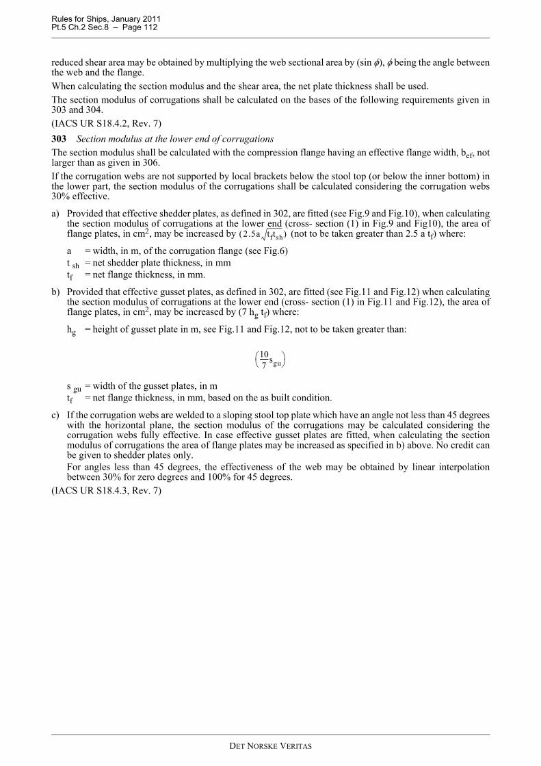
Rules for Ships, January 2011 Pt.5 Ch.2 Sec.8 – Page 112
reduced shear area may be obtained by multiplying the web sectional area by (sin φ), φ being the angle betweenthe web and the flange.When calculating the section modulus and the shear area, the net plate thickness shall be used.The section modulus of corrugations shall be calculated on the bases of the following requirements given in303 and 304.(IACS UR S18.4.2, Rev. 7)303 Section modulus at the lower end of corrugationsThe section modulus shall be calculated with the compression flange having an effective flange width, bef, notlarger than as given in 306.If the corrugation webs are not supported by local brackets below the stool top (or below the inner bottom) inthe lower part, the section modulus of the corrugations shall be calculated considering the corrugation webs30% effective.
a) Provided that effective shedder plates, as defined in 302, are fitted (see Fig.9 and Fig.10), when calculatingthe section modulus of corrugations at the lower end (cross- section (1) in Fig.9 and Fig10), the area offlange plates, in cm2, may be increased by (not to be taken greater than 2.5 a tf) where:
a = width, in m, of the corrugation flange (see Fig.6)t sh = net shedder plate thickness, in mmtf = net flange thickness, in mm.
b) Provided that effective gusset plates, as defined in 302, are fitted (see Fig.11 and Fig.12) when calculatingthe section modulus of corrugations at the lower end (cross- section (1) in Fig.11 and Fig.12), the area offlange plates, in cm2, may be increased by (7 hg tf) where:
hg = height of gusset plate in m, see Fig.11 and Fig.12, not to be taken greater than:
s gu = width of the gusset plates, in mtf = net flange thickness, in mm, based on the as built condition.
c) If the corrugation webs are welded to a sloping stool top plate which have an angle not less than 45 degreeswith the horizontal plane, the section modulus of the corrugations may be calculated considering thecorrugation webs fully effective. In case effective gusset plates are fitted, when calculating the sectionmodulus of corrugations the area of flange plates may be increased as specified in b) above. No credit canbe given to shedder plates only.For angles less than 45 degrees, the effectiveness of the web may be obtained by linear interpolationbetween 30% for zero degrees and 100% for 45 degrees.
(IACS UR S18.4.3, Rev. 7)
2.5a tftsh( )
107------sgu⎝ ⎠
⎛ ⎞
DET NORSKE VERITAS

Rules for Ships, January 2011 Pt.5 Ch.2 Sec.8 – Page 113
304 Section modulus of corrugations at cross-sections other than the lower endThe section modulus shall be calculated with the corrugation webs considered effective and the compressionflange having an effective flange width, bef, not larger than as given in 306.(IACS UR S18.4.4, Rev. 7)305 Allowable stress checkThe normal and shear stresses σ and τ, shall not exceed the allowable values σa and τa, in N/mm2, given by:
σa = σfτa = 0.5 σf
σf being the minimum upper yield stress, in N/mm2, of the material.(IACS UR S18.4.5, Rev. 7)
Fig. 9Symmetric shedder plates
Fig. 10Asymmetric shedder plates
DET NORSKE VERITAS

Rules for Ships, January 2011 Pt.5 Ch.2 Sec.8 – Page 114
Fig. 11Symmetric gusset/shedder plates
Fig. 12Asymmetric gusset/shedder plates
DET NORSKE VERITAS
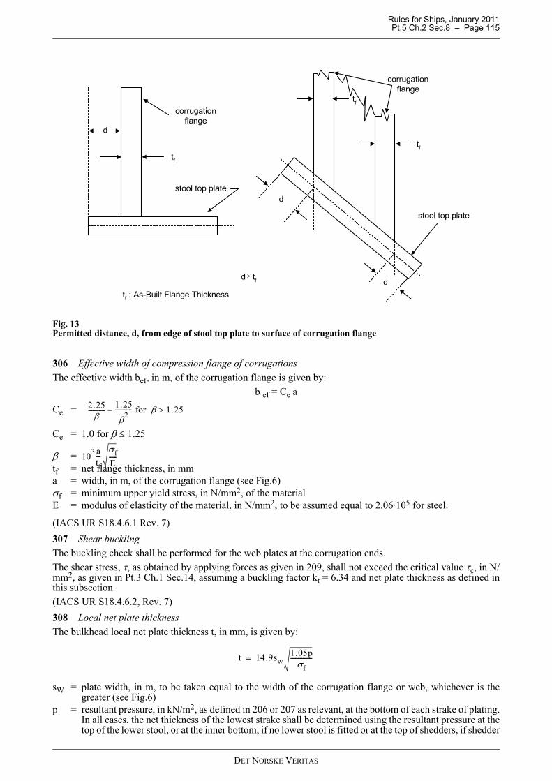
Rules for Ships, January 2011 Pt.5 Ch.2 Sec.8 – Page 115
Fig. 13Permitted distance, d, from edge of stool top plate to surface of corrugation flange
306 Effective width of compression flange of corrugationsThe effective width bef, in m, of the corrugation flange is given by:
b ef = Ce a
Ce =
Ce = 1.0 for β ≤ 1.25
β =tf = net flange thickness, in mma = width, in m, of the corrugation flange (see Fig.6)σf = minimum upper yield stress, in N/mm2, of the materialE = modulus of elasticity of the material, in N/mm2, to be assumed equal to 2.06·105 for steel.
(IACS UR S18.4.6.1 Rev. 7)307 Shear bucklingThe buckling check shall be performed for the web plates at the corrugation ends.The shear stress, τ, as obtained by applying forces as given in 209, shall not exceed the critical value τc, in N/mm2, as given in Pt.3 Ch.1 Sec.14, assuming a buckling factor kt = 6.34 and net plate thickness as defined inthis subsection.(IACS UR S18.4.6.2, Rev. 7)308 Local net plate thicknessThe bulkhead local net plate thickness t, in mm, is given by:
sW = plate width, in m, to be taken equal to the width of the corrugation flange or web, whichever is thegreater (see Fig.6)
p = resultant pressure, in kN/m2, as defined in 206 or 207 as relevant, at the bottom of each strake of plating.In all cases, the net thickness of the lowest strake shall be determined using the resultant pressure at thetop of the lower stool, or at the inner bottom, if no lower stool is fitted or at the top of shedders, if shedder
corrugationflange
stool top plate
d
tf
d
d
stool top plate
tf
corrugationflange
d tf≥
tf : As-Built Flange Thickness
tf
2.25β
----------- 1.25
β2----------- for β 1.25>–
103 atf---
σfE-----
t 14.9sw1.05p
σf--------------=
DET NORSKE VERITAS
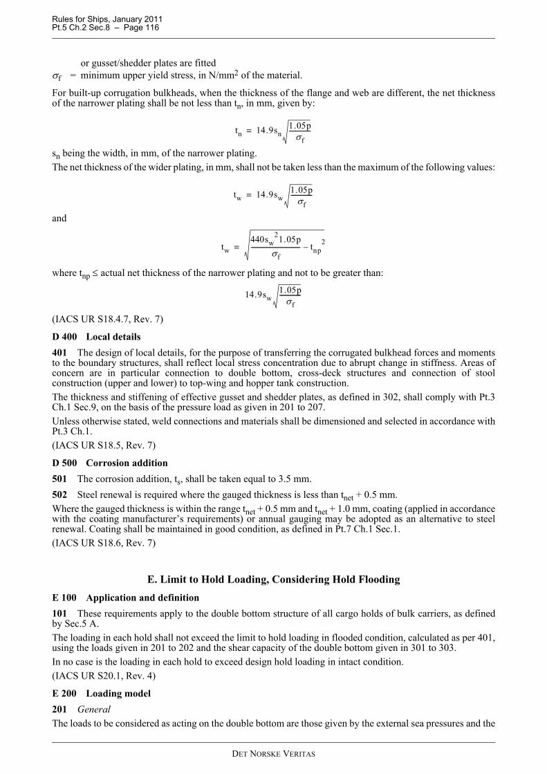
Rules for Ships, January 2011 Pt.5 Ch.2 Sec.8 – Page 116
or gusset/shedder plates are fittedσf = minimum upper yield stress, in N/mm2 of the material.
For built-up corrugation bulkheads, when the thickness of the flange and web are different, the net thicknessof the narrower plating shall be not less than tn, in mm, given by:
sn being the width, in mm, of the narrower plating.The net thickness of the wider plating, in mm, shall not be taken less than the maximum of the following values:
and
where tnp ≤ actual net thickness of the narrower plating and not to be greater than:
(IACS UR S18.4.7, Rev. 7)
D 400 Local details401 The design of local details, for the purpose of transferring the corrugated bulkhead forces and momentsto the boundary structures, shall reflect local stress concentration due to abrupt change in stiffness. Areas ofconcern are in particular connection to double bottom, cross-deck structures and connection of stoolconstruction (upper and lower) to top-wing and hopper tank construction.The thickness and stiffening of effective gusset and shedder plates, as defined in 302, shall comply with Pt.3Ch.1 Sec.9, on the basis of the pressure load as given in 201 to 207.Unless otherwise stated, weld connections and materials shall be dimensioned and selected in accordance withPt.3 Ch.1.(IACS UR S18.5, Rev. 7)
D 500 Corrosion addition501 The corrosion addition, ts, shall be taken equal to 3.5 mm.502 Steel renewal is required where the gauged thickness is less than tnet + 0.5 mm.Where the gauged thickness is within the range tnet + 0.5 mm and tnet + 1.0 mm, coating (applied in accordancewith the coating manufacturer’s requirements) or annual gauging may be adopted as an alternative to steelrenewal. Coating shall be maintained in good condition, as defined in Pt.7 Ch.1 Sec.1.(IACS UR S18.6, Rev. 7)
E. Limit to Hold Loading, Considering Hold FloodingE 100 Application and definition101 These requirements apply to the double bottom structure of all cargo holds of bulk carriers, as definedby Sec.5 A.The loading in each hold shall not exceed the limit to hold loading in flooded condition, calculated as per 401,using the loads given in 201 to 202 and the shear capacity of the double bottom given in 301 to 303.In no case is the loading in each hold to exceed design hold loading in intact condition.(IACS UR S20.1, Rev. 4)
E 200 Loading model201 GeneralThe loads to be considered as acting on the double bottom are those given by the external sea pressures and the
tn 14.9sn1.05p
σf--------------=
tw 14.9sw1.05p
σf--------------=
tw440sw
21.05pσf
-------------------------------- tnp2
–=
14.9sw1.05p
σf--------------
DET NORSKE VERITAS
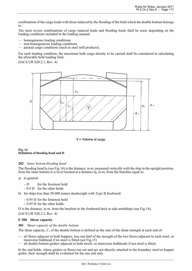
Rules for Ships, January 2011 Pt.5 Ch.2 Sec.8 – Page 117
combination of the cargo loads with those induced by the flooding of the hold which the double bottom belongsto.The most severe combinations of cargo induced loads and flooding loads shall be used, depending on theloading conditions included in the loading manual:
— homogeneous loading conditions— non-homogeneous loading conditions— packed cargo conditions (such as steel mill products).
For each loading condition, the maximum bulk cargo density to be carried shall be considered in calculatingthe allowable hold loading limit.(IACS UR S20.2.1, Rev. 4)
Fig. 14Definition of flooding head and D
202 Inner bottom flooding headThe flooding head hf (see Fig.14) is the distance, in m, measured vertically with the ship in the upright position,from the inner bottom to a level located at a distance df, in m, from the baseline equal to:
a) in general:
− D for the foremost hold− 0.9 D for the other holds
b) for ships less than 50 000 tonnes deadweight with Type B freeboard:
− 0.95 D for the foremost hold− 0.85 D for the other holds.
D is the distance, in m, from the baseline to the freeboard deck at side amidships (see Fig.14).(IACS UR S20.2.2, Rev. 4)
E 300 Shear capacity301 Shear capacity of the double bottomThe shear capacity, C, of the double bottom is defined as the sum of the shear strength at each end of:
— all floors adjacent to both hoppers, less one half of the strength of the two floors adjacent to each stool, ortransverse bulkhead if no stool is fitted (see Fig.15)
— all double bottom girders adjacent to both stools, or transverse bulkheads if not stool is fitted.
In the end holds, where girders or floors run out and are not directly attached to the boundary stool or hoppergirder, their strength shall be evaluated for the one end only.
DET NORSKE VERITAS
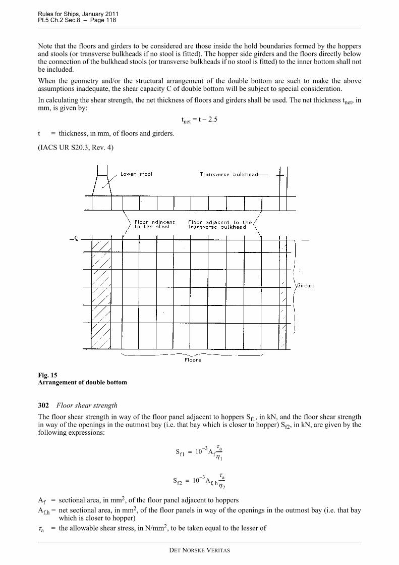
Rules for Ships, January 2011 Pt.5 Ch.2 Sec.8 – Page 118
Note that the floors and girders to be considered are those inside the hold boundaries formed by the hoppersand stools (or transverse bulkheads if no stool is fitted). The hopper side girders and the floors directly belowthe connection of the bulkhead stools (or transverse bulkheads if no stool is fitted) to the inner bottom shall notbe included.When the geometry and/or the structural arrangement of the double bottom are such to make the aboveassumptions inadequate, the shear capacity C of double bottom will be subject to special consideration.In calculating the shear strength, the net thickness of floors and girders shall be used. The net thickness tnet, inmm, is given by:
tnet = t − 2.5
t = thickness, in mm, of floors and girders.
(IACS UR S20.3, Rev. 4)
Fig. 15Arrangement of double bottom
302 Floor shear strengthThe floor shear strength in way of the floor panel adjacent to hoppers Sf1, in kN, and the floor shear strengthin way of the openings in the outmost bay (i.e. that bay which is closer to hopper) Sf2, in kN, are given by thefollowing expressions:
Af = sectional area, in mm2, of the floor panel adjacent to hoppersAf,h = net sectional area, in mm2, of the floor panels in way of the openings in the outmost bay (i.e. that bay
which is closer to hopper)τa = the allowable shear stress, in N/mm2, to be taken equal to the lesser of
Sf1 10 3– Afτaη1------=
Sf2 10 3– Af h,τaη2------=
DET NORSKE VERITAS
Rules for Ships, January 2011 Pt.5 Ch.2 Sec.8 – Page 119
For floors adjacent to the stools or transverse bulkheads, as identified in 301, τa may be taken as:
σF = minimum upper yield stress, in N/mm2, of the materials = spacing of stiffening members, in mm, of panel under considerationη1 = 1.10η2 = 1.20
η2 may be reduced down to 1.10 when appropriate reinforcements are fitted around openings.(IACS UR S20.3.1, Rev. 4)
303 Girder shear strengthThe girder shear strength in way of the girder panel adjacent to stools (or transverse bulkheads, if no stool isfitted) Sgl, in kN, and the girder shear strength in way of the largest opening in the outmost bay (i.e. that baywhich is closer to stool, or transverse bulkhead, if no stool is fitted) Sg2, in kN, are given by the followingexpressions:
Ag = minimum sectional area, in mm2, of the girder panel adjacent to stools (or transverse bulkheads, if nostool is fitted)
Ag,h = net sectional area, in mm2, of the girder panel in way of the largest opening in the outmost bay (i.e. thatbay which is closer to stool, or transverse bulkhead, if no stool is fitted)
τa = allowable shear stress, in N/mm2, as given in 302η1 = 1.10η2 = 1.15
η2 may be reduced down to 1.10 when appropriate reinforcements are fitted around openings.(IACS UR S20.3.2, Rev. 4)
E 400 Limit to hold loading, considering flooding
401 The limit to hold loading, W, in tonnes, is given by:
F = 1.1 in general= 1.05 for steel mill products
ρc = bulk cargo density, in t/m3 (see 201). For steel products, ρc shall be taken as the density of steelV = volume, in m3, occupied by cargo at a level h1
h1 =
X = for bulk cargoes, the lesser of X1 and X2 given by:
τa162σF
0.6
stnet--------⎝ ⎠
⎛ ⎞ 0.8---------------------- and
σF
3-------=
σF
3-------
Sg1 10 3– Agτaη1------=
Sg2 10 3– Ag h,τaη2------=
W ρcV1F---=
Xρcg--------
DET NORSKE VERITAS
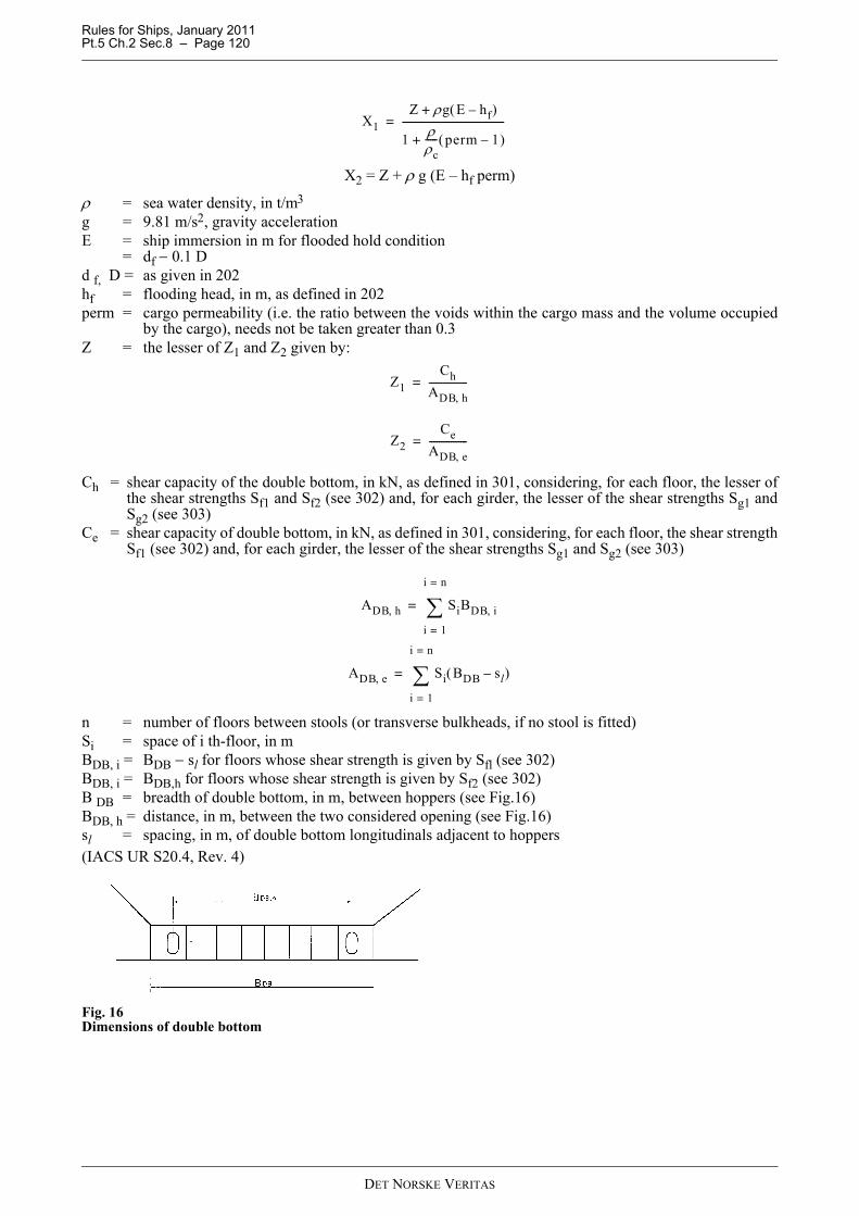
Rules for Ships, January 2011 Pt.5 Ch.2 Sec.8 – Page 120
X2 = Z + ρ g (E – hf perm)
ρ = sea water density, in t/m3
g = 9.81 m/s2, gravity accelerationE = ship immersion in m for flooded hold condition
= df − 0.1 Dd f, D = as given in 202hf = flooding head, in m, as defined in 202perm = cargo permeability (i.e. the ratio between the voids within the cargo mass and the volume occupied
by the cargo), needs not be taken greater than 0.3Z = the lesser of Z1 and Z2 given by:
Ch = shear capacity of the double bottom, in kN, as defined in 301, considering, for each floor, the lesser ofthe shear strengths Sf1 and Sf2 (see 302) and, for each girder, the lesser of the shear strengths Sg1 andSg2 (see 303)
Ce = shear capacity of double bottom, in kN, as defined in 301, considering, for each floor, the shear strengthSf1 (see 302) and, for each girder, the lesser of the shear strengths Sg1 and Sg2 (see 303)
n = number of floors between stools (or transverse bulkheads, if no stool is fitted)Si = space of i th-floor, in mBDB, i = BDB − sl for floors whose shear strength is given by Sfl (see 302)BDB, i = BDB,h for floors whose shear strength is given by Sf2 (see 302)B DB = breadth of double bottom, in m, between hoppers (see Fig.16)BDB, h = distance, in m, between the two considered opening (see Fig.16)sl = spacing, in m, of double bottom longitudinals adjacent to hoppers(IACS UR S20.4, Rev. 4)
Fig. 16Dimensions of double bottom
X1Z ρg E hf–( )+
1 ρρc----- perm 1–( )+
------------------------------------------=
Z1Ch
ADB h,----------------=
Z2Ce
ADB e,----------------=
ADB h, SiBDB i,
i 1=
i n=
∑=
ADB e, Si BDB sl–( )
i 1=
i n=
∑=
DET NORSKE VERITAS

Rules for Ships, January 2011 Pt.5 Ch.2 Sec.8 – Page 121
F. Evaluation of Scantlings of Hatch Covers and Hatch Coamings of Cargo Holds of Bulk Carriers, Ore Carriers and Combination Carriers
F 100 Application and definition101 These requirements are applicable to hatch covers and hatch coamings of stiffened plate construction.The secondary stiffeners and primary supporting members of the hatch covers shall be continuous over thebreadth and length of the hatch covers, as far as practical. When this is impractical, sniped end connectionsshall not be used and appropriate arrangements shall be adopted to ensure sufficient load carrying capacity.The spacing of primary supporting members parallel to the direction of secondary stiffeners shall not exceed1/3 of the span of primary supporting members, i.e. between rigid supports.The secondary stiffeners of the hatch coamings shall be continuous over the breadth and length of the hatchcoamings.These requirements are in addition to the requirements given in Pt.3 Ch.3 Sec.6.The net thickness, tnet, is the thickness necessary to obtain the below net minimum scantlings.The required thickness is obtained by adding the corrosion addition ts, given in 1 000 to the net thickness tnet.Material for the hatch covers shall be steel according to the requirements for ship's hull.The design of closing arrangements for all hatch covers shall comply with Pt.3 Ch.3 Sec.6.(IACS S21.1, Rev. 4, Corr. 1)
F 200 Hatch cover load model201 The pressure p, in kN/m2, on the hatch cover panels is given by:For ships of 100 m in length and above:
p ≥ 34.3, for hatch ways located at the freeboard deckp = 34.3, where a position 1 hatchway, as given in Pt.3 Ch.3 Sec.6 A202, is located at least one
superstructure standard height higher than the freeboard deck
where:
pFP = pressure at the forward perpendicular= 49.1 + (LF − 100) a
a = 0.0726 for type B freeboard ships= 0.356 for ships with reduced freeboard
LF = freeboard length, in m, as given in Pt.3 Ch.1 Sec.1 B100x = distance, in m, of the mid length of the hatch cover under examination from the forward end of LF.
For ships less than 100 m in length:
where:
p ≥ 0.195 LF +14.9, for hatch ways located at the freeboard deck.
Where two or more panels are connected by hinges, each individual panel shall be considered separately.(IACS S21.2, Rev. 4, Corr.1)
F 300 Hatch cover strength criteria301 Allowable stress checkThe normal and shear stresses σ and τ in the hatch cover structures shall not exceed the allowable values σaand τa, in N/mm2, given by:
σa = 0.80 σfτa = 0.46 σf.
σf being the minimum upper yield stress, in N/mm2, of the material.The normal stress in compression of the attached flange of primary supporting members shall not exceed 0.8
p 34.3pFP 34.3–
0.25----------------------- 0.25 x
LF------–⎝ ⎠
⎛ ⎞+=
p 15.8LF3
------ 1 53--- x
LF------–⎝ ⎠
⎛ ⎞ 3.6 xLF------–+=
DET NORSKE VERITAS
Rules for Ships, January 2011 Pt.5 Ch.2 Sec.8 – Page 122
times the critical buckling stress of the structure according to the buckling check as given in Pt.3 Ch.1 Sec.13.The stresses in hatch covers that are designed as a grillage of longitudinal and transverse primary supportingmembers shall be determined by a grillage or a FE analysis.When a beam or a grillage analysis is used, the secondary stiffeners shall not be included in the attached flangearea of the primary members.When calculating the stresses σ and τ, the net scantlings shall be used.In case of stiffeners of variable cross section, see Pt.3 Ch.3 Sec.6 E400.(IACS S21.3.1, Rev. 4, Corr. 1)302 Effective cross-sectional area of panel flanges for primary supporting membersThe effective flange area Af, in cm2, of the attached plating, to be considered for the yielding and bucklingchecks of primary supporting members, when calculated by means of a beam or grillage model, is obtained asthe sum of the effective flange areas of each side of the girder web as appropriate:
where:
nf = 2 if attached plate flange extends on both sides of girder web= 1 if attached plate flange extends on one side of girder web only
t = net thickness of considered attached plate, in mmbef = effective breadth, in m, of attached plate flange on each side of girder web
= bp, but shall not be taken greater than 0.165 lbp = half distance, in m, between the considered primary supporting member and the adjacent onel = span, in m, of primary supporting members
(IACS UR S21.3.2, Rev. 4, Corr. 1).303 Local net plate thicknessThe local net plate thickness t, in mm, of the hatch cover top plating shall not be less than:
but shall not be less than 1% of the spacing of the stiffener or 6 mm if that being greater.where:
Fp = factor for combined membrane and bending response= 1.50 in general= 1.90 σ/σa, for σ/σa ≥ 0.8; for the attached plate flange of primary supporting members
s = stiffener spacing, in mp = as given in 201σ = as given in 305σa = as given in 301
(IACS UR S21.3.3, Rev. 4, Corr.1)304 Net scantlings of secondary stiffenersThe required minimum net section modulus, in cm3, of secondary stiffeners of the hatch cover top plate, basedon stiffener net member thickness, are given by:
where:
l = secondary stiffener span, in m, shall be taken as the spacing of primary supporting members or the distancebetween a primary supporting member and the edge support, as applicable. When brackets are fitted at bothends of all secondary stiffener spans, the secondary stiffener span may be reduced by an amount equal to2/3 of the minimum brackets arm length, but not greater than 10% of the gross span, for each bracket
s = secondary spacing, in m.The net section modulus of the secondary stiffeners shall be determined based on an attached plate widthassumed equal to the stiffener spacing.
Af 10 bef t( )nf∑=
t Fp15.8s p0.95σf-----------------=
Z 1000 l2s p12 σa
----------------------=
DET NORSKE VERITAS
Rules for Ships, January 2011 Pt.5 Ch.2 Sec.8 – Page 123
(IACS UR S21.3.4, Rev. 4, Corr.1).
305 Net scantlings of primary supporting membersThe section modulus and web thickness of primary supporting members, based on member net thickness, shallbe such that the normal stress σ in both flanges and the shear stress τ, in the web, do not exceed the allowablevalues σa and τa, respectively, as given in 301.The breadth of the primary supporting member flange shall not be less than 40% of their depth for laterallyunsupported spans grater than 3.0 m. Tripping brackets attached to the flange may be considered as a lateral supportfor primary supporting members.The flange outstand shall not exceed 15 times the flange thickness.(IACS UR S21.3.5, Rev. 4, Corr.1).
F 400 Buckling
401 Buckling for hatch cover plating with primary supporting members parallel to the direction of secondarystiffeners shall be in accordance with Pt.3 Ch.1 Sec.13 B, with ψ = 1.0. Buckling for hatch cover plating with primary supporting members perpendicular to the direction of secondarystiffeners shall be in accordance with Pt.3 Ch.1 Sec.13 B.Buckling for secondary stiffeners shall be in accordance with Pt.3 Ch.1 Sec.13 C.For flat bar secondary stiffeners and buckling stiffeners, the ratio h/tw shall not be greater than:
where:
h = height of stiffenertw = net thickness of stiffenerBuckling for web panels of hatch cover primary supporting members shall be in accordance with Pt.3 Ch.1Sec.13 B300.For primary supporting members parallel to the direction of secondary stiffeners, the actual dimensions of thepanels shall be considered.For primary supporting members perpendicular to the direction of secondary stiffeners or for hatch covers builtwithout secondary stiffeners, a presumed square panel of dimension d shall be taken for the determination ofthe stress τc. In such a case, the average stress τ between the values calculated at the ends of this panel shall beconsidered.(IACS UR S21.3.6, Rev. 4, Corr.1)
F 500 Deflection limit and connections between hatch cover panels
501 Load bearing connections between the hatch cover panels shall be fitted with the purpose of restrictingthe relative vertical displacements.The vertical deflection of primary supporting members shall not be more than 0.0056 l, where l is the greatestspan of primary supporting members.(IACS UR S21.3.7, Rev. 4, Corr.1)
F 600 Hatch coaming load model
601 The pressure pcoam, in kN/m2, on the No.1 forward (foremost hold) transverse hatch coaming is given by:
pcoam = 220, when a forecastle is fitted in accordance to Sec.5 F= 290 in other cases.
The pressure pcoam on the other hatch coamings is given by:
pcoam = 220(IACS UR S21.4.1, Rev. 4, Corr.1)
F 700 Hatch coamings strength criteria
701 Local net plate thicknessThe local net plate thickness, in mm, of the hatch coaming plating is given by:
15 1f1----
DET NORSKE VERITAS

Rules for Ships, January 2011 Pt.5 Ch.2 Sec.8 – Page 124
where:
s = spacing, in m, of secondary stiffenerpcoam = as given in 601Scoam = safety factor
= 1.15σa,coam= 0.95 σfThe local net plate thickness shall not be less than 9.5 mm.(IACS UR S21.4.2, Rev. 4, Corr.1)
t 14.9spcoam
σa coam,-------------------Scoam=
DET NORSKE VERITAS

Rules for Ships, January 2011 Pt.5 Ch.2 Sec.8 – Page 125
702 Net scantlings of longitudinal and transverse secondary stiffenersThe required net section modulus in cm3, of the longitudinal or transverse secondary stiffeners of the hatchcoamings, based on net member thickness, is given by:
where:
m = 16 in general= 12 for the end spans of stiffeners sniped at the coaming corners
l = span, in m, of secondary stiffenerscp = ratio of the plastic section modulus to the elastic section modulus of the secondary stiffeners with an
attached plate breadth, in mm, equal to 40 t, where t is the plate net thickness= 1.16 in the absence of more precise evaluation
(IACS UR S21.4.3, Rev. 4, Corr.1)703 Net scantlings of coaming staysThe required minimum net section modulus, in cm3, and net web thickness, in mm, of coamings stays designedas beams with flange connected to the deck or sniped and fitted with a bracket, see Fig.17, at their connectionwith the deck, based on member met thickness, are given by:
where
HC = stay height, in mS = stay spacing, in mh = stay depth, in mm, at the connection with the deckτa,coam= 0.5 σf
Fig. 17
For calculating the section modulus of coaming stays, their face plate area shall be taken into account onlywhen it is welded with full penetration welds to the deck plating and adequate under deck structure is fitted tosupport the stresses transmitted by it.For other designs of coaming stays, such as for example those shown in Fig.18, the stress levels as given in 301apply and shall be checked at the highest stressed locations.
Z1000 Scoam l2s pcoam
m cp σa coam,-------------------------------------------------=
Z1000 Hc
2s pcoam2 σa coam,
---------------------------------------=
tw1000 Hc s pcoam
h τa coam,------------------------------------=
DET NORSKE VERITAS
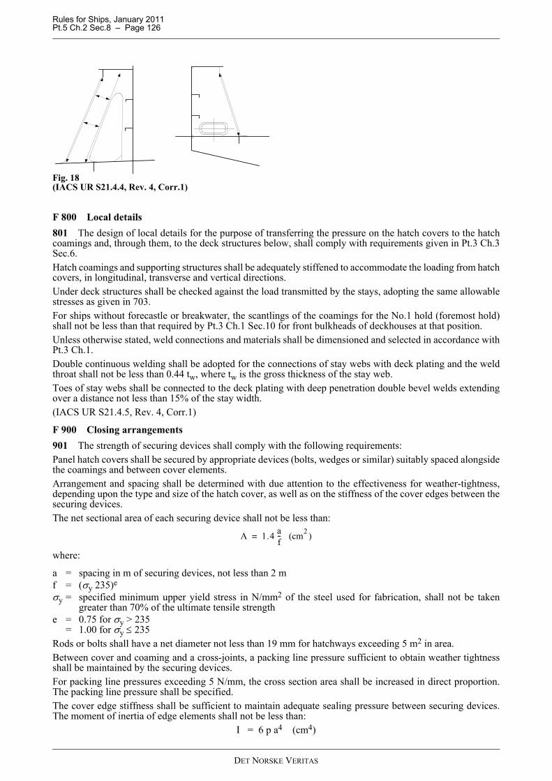
Rules for Ships, January 2011 Pt.5 Ch.2 Sec.8 – Page 126
Fig. 18(IACS UR S21.4.4, Rev. 4, Corr.1)
F 800 Local details801 The design of local details for the purpose of transferring the pressure on the hatch covers to the hatchcoamings and, through them, to the deck structures below, shall comply with requirements given in Pt.3 Ch.3Sec.6.Hatch coamings and supporting structures shall be adequately stiffened to accommodate the loading from hatchcovers, in longitudinal, transverse and vertical directions.Under deck structures shall be checked against the load transmitted by the stays, adopting the same allowablestresses as given in 703.For ships without forecastle or breakwater, the scantlings of the coamings for the No.1 hold (foremost hold)shall not be less than that required by Pt.3 Ch.1 Sec.10 for front bulkheads of deckhouses at that position.Unless otherwise stated, weld connections and materials shall be dimensioned and selected in accordance withPt.3 Ch.1.Double continuous welding shall be adopted for the connections of stay webs with deck plating and the weldthroat shall not be less than 0.44 tw, where tw is the gross thickness of the stay web.Toes of stay webs shall be connected to the deck plating with deep penetration double bevel welds extendingover a distance not less than 15% of the stay width.(IACS UR S21.4.5, Rev. 4, Corr.1)
F 900 Closing arrangements901 The strength of securing devices shall comply with the following requirements:Panel hatch covers shall be secured by appropriate devices (bolts, wedges or similar) suitably spaced alongsidethe coamings and between cover elements.Arrangement and spacing shall be determined with due attention to the effectiveness for weather-tightness,depending upon the type and size of the hatch cover, as well as on the stiffness of the cover edges between thesecuring devices.The net sectional area of each securing device shall not be less than:
where:
a = spacing in m of securing devices, not less than 2 mf = (σy 235)e
σy = specified minimum upper yield stress in N/mm2 of the steel used for fabrication, shall not be takengreater than 70% of the ultimate tensile strength
e = 0.75 for σy > 235= 1.00 for σy ≤ 235
Rods or bolts shall have a net diameter not less than 19 mm for hatchways exceeding 5 m2 in area.Between cover and coaming and a cross-joints, a packing line pressure sufficient to obtain weather tightnessshall be maintained by the securing devices.For packing line pressures exceeding 5 N/mm, the cross section area shall be increased in direct proportion.The packing line pressure shall be specified.The cover edge stiffness shall be sufficient to maintain adequate sealing pressure between securing devices.The moment of inertia of edge elements shall not be less than:
I = 6 p a4 (cm4)
A 1.4 af-- (cm2 )=
DET NORSKE VERITAS
Rules for Ships, January 2011 Pt.5 Ch.2 Sec.8 – Page 127
where:
p = packing line pressure in N/mm, minimum 5 N/mma = spacing in m of securing devicesSecuring devices shall be of reliable construction and securely attached to the hatchway coamings, decks orcovers. Individual securing devices on each cover shall have approximately the same stiffness characteristics.Where rod cleats are fitted, resilient washers or cushions shall be incorporated.Where hydraulic cleating is adopted, a positive means shall be provided to ensure that it remains mechanicallylocked in the closed position in the event of failure of the hydraulic system.(IACS UR S21.5.1, Rev. 4, Corr.1)902 Hatch covers shall be effectively secured, by means of stoppers, against the transverse forces arisingfrom a pressure of 175 kN/m2.With the exclusion of the No. 1 (foremost hold) hatch cover, hatch covers shall be effectively secured, by meansof stoppers, against the longitudinal forces acting on the forward end arising from a pressure of 175 kN/m2.The No. 1 (foremost hold) hatch cover shall be effectively secured, by means of stoppers, against the longitudinalforces acting on the forward end arising from a pressure of 230 kN/m2.This pressure may be reduced to 175 kN/m2 when a forecastle is fitted in accordance with Sec.5 F.The equivalent stress:
— in stoppers and their supporting structures, and— calculated in the throat of the stopper welds
shall not exceed the allowable value of 0.8 σy.
(IACS UR S21.5.2, Rev. 4, Corr.1)903 Stoppers or securing devices shall be manufactured of materials, including welding electrodes, meetingrelevant IACS requirements.(IACS UR S21.5.3, Rev. 4, Corr.1)
F 1000 Corrosion addition and steel renewal1001 Hatch coversFor all the structures (plating and stiffeners) of single skin hatch cover, the corrosion addition ts shall be 2.0 mm.For double skin hatch covers, the corrosion addition shall be taken equal to:
— 2.0 mm for the top and bottom plating— 1.5 mm for the internal structures.
For single skin hatch covers and for the plating of double skin hatch covers, steel renewal is required where thegauged thickness is less than
tnet + 0.5 mm.Where the gauged thickness is within the range tnet + 0.5 mm and tnet + 1.0 mm, coating (applied in accordancewith the coating manufacturer's requirements) or annual gauging may be adopted as an alternative to steelrenewal. Coating shall be maintained in good condition, as defined in Pt.7 Ch.1 Sec.1.For the internal structure of double skin hatch covers, thickness gauging is required when plating renewal shallbe carried out or when this is deemed necessary, at the discretion of the surveyor, on the basis of the platingcorrosion or deformation condition. In these cases, steel renewal for the internal structures is required wherethe gauged thickness is less than tnet.(IACS UR S21.6.1, Rev. 4, Corr.1)
1002 Hatch coamingsFor the structure of hatch coamings and coaming stays, the corrosion addition ts shall be 1.5 mm.Steel renewal is required where the gauged thickness is less than
tnet + 0.5 mm.Where the gauged thickness is within the range tnet + 0.5 mm and tnet + 1.0 mm, coating (applied in accordancewith the coating manufacturer's requirements) or annual gauging may be adopted as an alternative to steelrenewal. Coating shall be maintained in good condition, as defined in Pt.7 Ch.1 Sec.1.(IACS UR S21.6.2, Rev. 4, Corr.1)
DET NORSKE VERITAS

Rules for Ships, January 2011 Pt.5 Ch.2 Sec.9 – Page 128
SECTION 9 SHIPS SPECIALISED FOR THE CARRIAGE OF A SINGLE TYPE OF DRY BULK CARGO
A. General
A 100 Classification101 The requirements in this section apply to ships intended for the carriage of a single cargo type. Thenotation X Carrier may be given to ships built in compliance with the requirements in this section, where Xdenotes the type of cargo to be carried, e.g. Alumina, Cement, Sugar etc.102 The cargo holds shall be arranged with a closed loading and unloading arrangement. Documentation ofthe intended loading and unloading system shall be submitted for information.103 The ship is, in general, to have a double bottom within the cargo region and have double sides and asingle deck. Hatches to cargo holds shall be arranged as required for access only, and for the closed loadingand unloading arrangement.
A 200 Documentation201 Data regarding properties of the cargo, relevant to the design (e.g. bulk density, angle of repose, humiditylimit, etc.) shall be submitted for information.202 Information regarding the intended cargo and ballast conditions, including typical loading and unloadingsequences, shall be submitted for approval. This shall include conditions with uneven distribution of cargobetween holds, e.g. part loading conditions with empty cargo holds, as applicable.
A 300 Design loads301 The design pressures for local elements, i.e. plates and stiffeners, shall be as given in Pt.3 Ch.1 Sec.4,using parameters as given in 200, as applicable.302 In the direct calculations, design pressures shall be as given in Pt.3 Ch.1 Sec.13, using the informationgiven in 200.
A 400 Longitudinal strength401 The longitudinal strength shall be determined as given in Pt.3 Ch.1 Sec.5 or Pt.3 Ch.2 Sec.4. The shipsshall belong to category I, see Pt.3 Ch.1 Sec.5 D or Pt.3 Ch.2 Sec.4 A. Ships intended for the carriage ofhomogeneous loads only, may upon request, be considered according to the requirements for ships in categoryII.
A 500 Plating and stiffeners501 The plate thickness and the cross-sectional properties of stiffeners are in general to be calculated as givenin Pt.3 Ch.1 or Pt.3 Ch.2, using design pressures according to 200 where applicable.502 The minimum thickness of the inner bottom plating of the double bottom of cargo holds, shall be takenas given in Pt.3 Ch.1 Sec.6 C402 or Pt.3 Ch.2 Sec.5 C302 for ships with length less than 100 m, with to = 5 mm.503 The section modulus of longitudinal stiffeners of double bottom structures shall be calculated, as givenin Pt.3 Ch.1 Sec.6, with double bottom stress σ db = 20 f1 N/mm2. For ships designed for non-homogeneousseagoing loading conditions, the section modulus of double bottom longitudinals is also to be calculated, asgiven in Sec.5 C300, based on double bottom stresses as is determined according to 600.
A 600 Girder systems601 Scantlings of girder structures of the bottom, sides, transverse bulkheads and deck of the cargo regionmay have to be determined, based on a direct stress analysis, as considered necessary by the Society.602 In cases where direct calculations are considered necessary, the following cases are normally to beconsidered:
a) Cargo unevenly distributed between the holds (harbour). The design condition shall be based on theintended loading and unloading sequence.
b) Cargo unevenly distributed between the holds, as applicable, according to the ship's loading manual(seagoing).
c) Ballast condition (seagoing).
DET NORSKE VERITAS

Rules for Ships, January 2011 Pt.5 Ch.2 Sec.10 – Page 129
SECTION 10 CARRIAGE OF REFRIGERATED CONTAINERS
A. ClassificationA 100 Application101 The rules, as relevant, in this chapter apply to ships equipped to carry refrigerated containers in hold and/or on deck when the class notation in A200 is requested.102 In this regard refrigerated container means a container with a self-contained refrigeration system, locatedwithin the containers outer dimensions and driven by electrical power fed from an external power supply. Thismay be a clip-on or an integral unit.103 These rules do not cover alarm and monitoring systems fitted to the individual containers.104 Vessels with novel arrangement and design not directly covered by these rules may also be given thenotations described in A200 after special consideration with respect to documentation and testing.
A 200 Class notations201 Ships designed, built, equipped and tested under the supervision of the Society in compliance with therequirements of this section may be given the additional class notation RC-1, RC-2 or RC-3.202 Class notation RC-1 is intended for vessels that carry mostly fruit (bananas) and chilled cargo in additionto deep frozen cargoes, i.e. a design ratio between 80% and 100% chilled cargo.203 Class notation RC-2 is intended for vessels that carry both frozen and chilled cargo with a design ratioof between 50% and 80% chilled cargo.204 Class notation RC-3 is mainly intended for vessels that carry mostly deep frozen cargoes with a designratio below 50% chilled cargo.205 For ships with class notations as given in 202 to 204, will in addition be given a notation of the maximumnumber of forty-foot equivalent refrigerated units (FEU) that may be carried, e.g. (200/70) meaning that thevessel may carry 200 reefer containers on deck and 70 in the holds.206 The following information shall be provided:
— details of ambient conditions— exact design ratio of chilled cargo — number of containers that may be loaded which are not at their predetermined set temperature.
This information will be included in the Appendix to the Classification Certificate.
B. Operational PerformanceB 100 General101 The ship shall be designed, arranged and equipped to make it suitable for carrying cargoes as relevantaccording to the design operating conditions and class notation. The builders and possible subcontractorsspecifications of the ships operational performances and abilities will together with the specific requirementsof this chapter will be used as basis for assignment of class.102 It is assumed that the refrigerated containers in general are at their predetermined set temperature at thetime of loading. If containers shall be loaded which are not at their predetermined set temperature this shall betaken into consideration when calculating the capacity required for the electrical and ventilation systems.103 It is assumed that the container refrigeration units are capable of functioning fully at an ambienttemperature of +50°C.
C. DocumentationC 100 Plans and particulars101 The following plans and particulars shall be submitted for approval, if applicable:
a) General
DET NORSKE VERITAS

Rules for Ships, January 2011 Pt.5 Ch.2 Sec.10 – Page 130
— The builders and possible subcontractors specifications of the ships operational performances andabilities, for information.
b) Ventilation arrangement
— Location and installation details of ventilation system showing duct arrangement and sizes, for eachhole, including schematic arrangement of the ventilation system showing proposed air volume andvelocity at junctions.
— Details of all fans including location, number, design condition, capacities and power consumption.— Details or air inlets and outlets including number, type, size and location.— Details and location of dampers and flaps, if applicable.— Calculation of specified air through put rate and proposals for it’s measurement.— Design temperature rise in the hold space and corresponding ambient air temperature and relative
humidity.— Cooling water systems for containers equipped with water cooled condensers (fresh and sea water).
c) Hull structure
— Refrigerated container stowage plans.— Design pressure or vacuum in each hold.— Details of hatch cover sealing arrangements.— Personnel access arrangements.— Details of any pressure/vacuum safety valves in each hold space.— Details of associated openings through the hull structure.
d) Electrical installations, in accordance with the requirements of Pt.4 Ch.8
— Calculation of electric power demand covering all refrigerated containers and the necessary fans.
e) Control and monitoring system
— Ventilation control and monitoring.— Refrigerating container supply monitoring
For documentation types, see Pt.4 Ch.9.f) Testing
— Details of the testing and commissioning programme, including description and set-up ofinstrumentation to be used to verify installation.
D. Ventilation and Hold TemperatureD 100 General101 Means shall be provided to remove the waste heat, from each container refrigerant condenser andelectrical motors, local to the condenser’s air outlet. This shall be arranged in such a way as to minimize theeffect on the hold space temperature. This may be accomplished by the use of a ventilation system or acombination of ventilation and water cooling.102 Air distribution systems to be provided for air supply directed to each container refrigeration unit.103 Separate supply air duct and fan shall be provided for each stack intended for refrigerated containers,except for the outermost stacks and in way of access to hold which may be arranged such that one duct splitsinto two.104 The positions of supply air inlets and exhaust air outlets shall be such as to reduce the possibility of shortcircuit. The effect heat ingress from deck stowed containers into the hold as well as the effects of warm exhaustair on deck stowed containers shall be considered.105 Air flow resistance between container refrigeration units and the exhaust air outlets shall be minimised.Restrictions to the free air flow by walkways etc. shall be kept to a minimum.106 Where container holds are designed for simultaneous carriage of 8’6’’ and 9’6’’ containers theventilation supply outlets must be adjustable to allow direct air supply to the containers condenser independentof the stowage pattern.
Guidance note:Since most refrigerated containers are high cube containers (9’6’’) it is advisable to optimise the reefer positions forthis size of container. Reference is also made to G104 concerning access to reefer containers.
---e-n-d---of---G-u-i-d-a-n-c-e---n-o-t-e---
DET NORSKE VERITAS

Rules for Ships, January 2011 Pt.5 Ch.2 Sec.10 – Page 131
107 Fans shall be controlled centrally from a position outside of the hold. In addition means of stopping allventilation fans shall be provided (outside the spaces being served) at positions which will not be cut-off in theevent of fire in the hold. Arrangements shall be provided to permit a rapid shutdown and effective closure ofthe ventilation system in each hold space in case of fire. 108 A minimum of one replacement fan, or fan motor, of each size shall be carried onboard. Fans shall bearranged to enable each to be replaced whilst the remaining parts of the system continue in operation.109 Cargo hold ventilation inlet and exhaust openings shall be arranged such that air supply to therefrigerated containers will be ensured also under heavy weather conditions.
D 200 Air supply201 The ambient climatic conditions are in general not to be taken less than air 35°C, seawater 32°C andrelative humidity 70%.202 The permissible cargo hold temperature is in general not to exceed 45°C.203 The air supply for each container with air cooled condensers shall not be taken less than:
where
Pcont= Power demand for reefer unit, not to be taken less than:= minimum 11.0 kW for 40’ and 8.4 kW for 20’ for
RC-1 notation (80% chilled)= minimum 9.8 kW for 40’ and 7.4 kW for 20’ for
RC-2 notation (50% chilled)= minimum 8.6 kW for 40’ and 6.4 kW for 20’ for
RC-3 notation (100% frozen).For other cargo mix linear interpolation may be used.
Pfan = Power demand for fans, kW.Qresp= Respiration from reefer containers
= 64 W/t for RC-1 notation, carriage of bananas= 0 for RC-2 and RC-3 notation.
QT = Heat transfer from adjacent tanks, heated above 45°C, kW.cair = Specific heat capacity of air, 1.01 kJ/(kg K) (at +35°C, 70% RH and 101.3 kPa).ρair = Density of air, 1.13 kg/m3 (at +35°C, 70% RH and 101.3 kPa).Thold= Maximum allowable hold temperature, in general not to be taken more than 45°C.Tair = Temperature of air at design ambient condition, in general not to be taken less than 35°C.
204 For containers with water cooled condenser the required air supply shall be calculated in accordance with203 using the following power demand for the containers:
Pcont= Power demand for reefer unit, not to be taken less than minimum 2.1 kW for 40’ and 1.5 kW for 20’.
205 Additional capacity shall be added for ships where containers shall be loaded which are not at theirpredetermined set temperature.
E. Electrical Installations
E 100 General101 The electrical installations shall comply with Pt.4 Ch.8. Reefer containers and ventilation systems shallbe considered as important services in all sailing and manoeuvring modes planned for the vessel. However,diversity factors (simultaneous factors) as given in paragraph 104 may be used.102 Under sea-going conditions, the number and rating of service generators shall be sufficient to supply allcontainer socket outlets and the hold space ventilation system in addition to services listed in Pt.4 Ch.8 Sec.2B101 b), when any one generator set is out of service.103 The number and rating of all service generators shall be sufficient to supply all container sockets and thehold space ventilation system in addition to the consumers needed under manoeuvring conditions.104 When calculating the electric power demand the following simultaneous factors may be applied to
QPcont Pfan Qresp QT+ + + 3600
ρair cair Thold Tair–( )---------------------------------------------------------------------------------- (m3 h )⁄=
DET NORSKE VERITAS

Rules for Ships, January 2011 Pt.5 Ch.2 Sec.10 – Page 132
account for the fact that not all refrigerating units are running at the same time:
Lower values may be applied to account for different cargo mixes, such lower values shall be documented.Additional capacity shall be added for ships where containers shall be loaded which are not at theirpredetermined set temperature.105 Socket connections for refrigerated containers shall be supplied from distribution boards, not directlyfrom the main switchboard. The supply to these distribution boards shall be divided approximately equallybetween the two sides of the main switchboard with one separate supply for each distribution panel.The number of container sockets connected to one final circuit shall not exceed 10.
Guidance note:The electric power supply to refrigerated container sockets should preferably be galvanic isolated from the ship mainsto avoid any influence in case of insulation faults. These rules do not include any requirements to earth faultdisconnection or earth fault indication for individual reefer containers.
---e-n-d---of---G-u-i-d-a-n-c-e---n-o-t-e---
Guidance note:It is not required that the generating capacity connected to each side of the main switchboard is sufficient to supplypower to all reefer containers.
---e-n-d---of---G-u-i-d-a-n-c-e---n-o-t-e---
106 Distribution panels with feeder circuits for reefer containers shall provide individual indications for eachoutgoing feeder showing when a feeder breaker is switched on.
F. Instrumentation and Control SystemF 100 General101 The control and monitoring systems shall comply with Pt.4 Ch.9.102 An alarm system for monitoring of the reefer containers and required auxiliary ship systems shall beinstalled. This system may be integral with the ship’s main alarm and monitoring system as long as a propergrouping is arranged in order to separate container alarms from other types of alarms (e.g. machinery alarms).This also covers extension alarms, where any container alarms shall not disturb personnel without cargoresponsibilities.
Guidance note:These rules do not require that the alarms for refrigerated containers are routed through an extension alarm system.
---e-n-d---of---G-u-i-d-a-n-c-e---n-o-t-e---
F 200 Ventilation alarm system201 A separate alarm shall be initiated upon failure of each independent ventilation system in each hold. If abalanced ventilation (mechanical exhaust and supply) system is installed, alarm for failure of each individualpart shall be given.
F 300 Cargo refrigerating system301 A separate alarm shall be initiated upon power supply failure to each refrigerating container circuit.302 Ships designed for the carriage of more than 150 reefer containers shall be equipped with a remote reefercontainer monitoring system of power cable transmission type in accordance with a recognised standard e.g.ISO10368.
G. Hold AccessG 100 General101 Suitable means shall be provided to allow personnel safe access to the hold when the ventilation system
Number of refrigerated FEU Simultaneous factor≤100 FEU 0.9>100 FEU 0.84>250 FEU 0.80>500 FEU 0.77
DET NORSKE VERITAS
Rules for Ships, January 2011 Pt.5 Ch.2 Sec.10 – Page 133
is in operation. Consideration shall be given to the possible over-pressure that may occur in the hold space.102 The maximum permitted pressure or vacuum that may occur in the hold shall be stated. If the ventilationsystem is capable of producing a positive pressure above this allowable figure, means shall be provided toprotect the hold and personnel from the effect of over-pressure or vacuum.103 Consideration shall be given to the use of a pressure/vacuum relief valve set to operate below themaximum allowable hold pressure/vacuum.104 Suitable accesses shall be provided to allow the removal of each refrigerated container’s compressor orelectrical motor. Access from each applicable hold space to the designated container refrigeration equipmentmaintenance area, shall be given.105 Access shall be provided for maintenance and replacement of the cargo hold fans in all loadingconditions.
H. Inspection and TestingH 100 General101 Trials of the system in each hold space shall be witnessed onboard by DNV surveyors before the systemis put into service and prior to a certificate being issued.102 The ability of the ventilation system to supply and/or extract air at the specified flow rate at each outletshall be verified by the test. The deviation from the rated flow should be maximum ±10%.103 Verification of function of hold ventilation system with exhaust outlets closed on one side of the vessel.104 Control and alarm systems shall be tested to demonstrate their correct operation. Testing shall take intoaccount the electric power supply arrangements.
DET NORSKE VERITAS

Rules for Ships, January 2011 Pt.5 Ch.2 Sec.11 – Page 134
SECTION 11 GREAT LAKES BULK CARRIERS
A. General
A 100 Introduction
101 BackgroundsThese rules describe relevant requirements for Bulk Carriers navigating on the Great Lakes and St. LawrenceSeaways.
102 ScopeThis section describes the following subjects:
— Design principles— Longitudinal strength— Hull structures— Anchoring and mooring equipment— Openings and closings appliances.
103 ObjectiveThe objective of this section is to ensure that the specific conditions for Bulk Carriers operating on the GreatLakes and St Lawrence river are met by describing additional requirements to and deviations from our standardmain class requirements.
104 ApplicationThe Rules in this section apply to Bulk Carriers designed to operate within the limits of the Great Lakes andthe St. Lawrence River to the seaward limits defined by the Anticosti Island. The requirements shall beregarded as supplementary to those given for the assignment of main class.These Rules are applicable to steel ships designed to carry dry cargo in bulk. Typically, the ships are designedas single deck ships with cargo holds of double bottom and double side construction. Hopper side tanks andtop-wing tanks may be fitted below the upper deck. Ships built in compliance with the modifications and additional requirements as given in this chapter, will beassigned the type and service notation: Great Lakes Bulk Carrier.
B. Requirements
B 100 General
101 The vessel shall meet the requirements of the service area notation RE taking into account the specificrequirement as described in this section.
102 The flag authority whose domestic requirements are being applied under the provision of Ch.1 Sec.2A307 (local trade), shall be indicated in parentheses after the service area notation, e.g. RE (can).
Guidance note:For vessels under Canadian registration, the assignment of the load line shall be in accordance with the CanadianShipping Act Load Line Regulation (inland).
---e-n-d---of---G-u-i-d-a-n-c-e---n-o-t-e---
B 200 Structural configuration
201 The Rules are applicable to ships designed as single deck ships with cargo holds of double bottom anddouble side construction. Hopper side tanks and top-wing tanks may be fitted below the upper deck.
B 300 Number of transverse watertight bulkheads
301 The number of transverse bulkheads shall be taken in accordance with Pt.3 Ch.1 Sec.3 A301.
302 Based on the structural configuration as described in 201, watertight bulkheads will not be required fittedbetween the cargo holds.
DET NORSKE VERITAS
Rules for Ships, January 2011 Pt.5 Ch.2 Sec.11 – Page 135
B 400 Position of collision bulkhead401 The distance xc’ from the forward perpendicular to the collision shall be taken as:
xc’ = 0.04LFwhereLF = load line length in m as defined in Pt.3 Ch.1 Sec.1 B.
C. Longitudinal StrengthC 100 Still Water and Wave Induced Hull Girder Bending Moments and Shear Forces101 Design hull girder moments and shear forces are to be taken in accordance with Pt.3 Ch.1 Sec.5 B.
C 200 Bending strength and stiffness201 Minimum midship section modulus about the transverse neutral axis shall be taken as given in Pt.3 Ch.1Sec.5 C302. For ships with service restriction RE, the reduction of the wave coefficient factor CWO as specifiedin C302 may be replaced by a reduction of 50%.202 The section modulus requirements about the transverse neutral axis based on cargo and ballast conditionsshall be taken as given in Pt.3 Ch.1 Sec.5 C303.
D. Hull Structures
D 100 Bottom structures101 Requirements to strengthening for bottom slamming loads as given in Pt.3 Ch.1 Sec.6 H200 need not becomplied with.
D 200 Side structure201 Requirements to strengthening for bow impact loads as given in Pt.3 Ch.1 Sec.7 E100 need not becomplied with.
Guidance note:Operational experience indicates that navigation in the Seaway locks and in light ice may cause contact damages toplating and framing in fore and aft shoulder areas. In order to reduce the risk of local structural deformations, it isadvised that this is considered in the design.
---e-n-d---of---G-u-i-d-a-n-c-e---n-o-t-e---
D 300 Transverse bulkheads301 The collision bulkhead shall have a minimum thickness not less than 12% greater than the requiredthickness of the dry cargo bulkheads. Minimum section modulus of stiffeners shall not be less than 25% greaterthan the required section modulus of stiffeners on the dry cargo bulkheads.302 For non-watertight bulkheads in the cargo region, the minimum thickness of plating shall not be less than9.5 mm in the upper part, and 12 mm in the lower part.
E. Anchoring and mooring equipmentE 100 Equipment101 Two bower anchors of mass in accordance with calculated equipment number, and stud-link chain cableof total length 330 m to be provided onboard. 102 Stern anchor to be fitted as required by the St. Lawrence Seaways Authority.
E 200 Equipment number201 The equipment number (EN’) is given by the formula:
EN’ = 0.3LSBD + a + bwhere:
a = addition for the 1st tier of superstructure and deck houses.
DET NORSKE VERITAS

Rules for Ships, January 2011 Pt.5 Ch.2 Sec.11 – Page 136
17.6% of volume of 1st tier (length × breadth × height)b = addition for the 2nd tier of deckhouses and other erections.
13.2% of the volume of the 2nd tier (length × breadth × height).
F. Openings and Closing AppliancesF 100 General101 Coaming and sill heights, closing appliances, freeing port areas, air pipes, ventilators, sanitary dischargesetc. shall be in accordance with the requirements in Pt.3 Ch.3 Sec.6, except as otherwise specified in thissubsection.102 DoorsDoors in Position 1 or Position 2 shall have a sill height, measured from the deck, of at least 300 mm.103 HatchwaysHatchways are to be fitted with efficiently constructed weathertight hatchway covers. The height above deckof hatchway coamings shall be at least 460 mm in Position 1 and at least 300 mm in Position 2. The coamingheight may be reduced if the hatchway is fitted with a watertight cover.104 Cargo ports and other similar openingsThe lower edge of cargo ports and other similar openings shall not be below a line drawn parallel to thefreeboard deck at side that has the upper edge of the uppermost load line at its lowest point.105 Machinery space openingsThe lower edge of any access opening in the casing shall be at least 300 mm above the deck.If the opening is a funnel or machinery space ventilator that needs to be kept open for the essential operationof the vessel, then the coaming height is to be at least 3.8 m in Position 1 and 1.8 m in Position 2.106 VentilatorsVentilator coamings shall be at least 760 mm above deck in Position 1 and at least 600 mm above deck inPosition 2. Ventilator openings shall have permanently attached weather tight means of closing. The requirement for weather tight closing appliances is not applicable for ventilators in Position 1 withcoamings that extend 3.8 m or more above the deck or to ventilators in Position 2 with coamings that extend1.8m or more above deck.107 Air pipesAir pipes are to have a coaming height of at least 760 mm on the freeboard deck, 600 mm on raised quarterdecks and 300 mm other superstructure decks.108 Freeing portsThe freeing port area is to be calculated as described in DNV Ship Rules Pt.3 Ch.3 Sec.6 with due attention toadjustments due to the height of the bulwark as given below:The freeing port area shall be increased by 0.04 m² per metre of length of the well for each metre that the heightof the bulwark exceeds
— 600 mm, in the case of vessels that are 73 m in length or less;— 1200 mm, in the case of vessels that are 146 m in length or more; and— In the case of vessels that are of intermediate length, the height obtained by linear interpolation between
the heights set out in paragraphs a) and b).
109 Scuppers, Drains, Inlets and Discharges
1) Every discharge pipe passing through the shell from spaces below the freeboard deck shall have
a) an automatic non-return valve fitted at the shell with a positive means of closing that is operable
i) from above the freeboard deck, orii) from a readily accessible location if the discharge originates in a space that is crewed or equipped
with a means of continuously monitoring the level of bilge water; or
b) two automatic non-return valves, one of which is fitted at the shell and one inboard that is accessiblefor examination when the vessel is in service.
DET NORSKE VERITAS
Rules for Ships, January 2011 Pt.5 Ch.2 Sec.11 – Page 137
2) Every discharge pipe that passes through the shell from within an enclosed superstructure, or from withina deckhouse that protects openings to below the freeboard deck, shall:
a) meet the requirements set out in paragraph 1) a) or b); orb) have an automatic non-return valve fitted at the shell, if the discharge originates in a space that is
regularly visited by the crew.
3) Every scupper, drain or discharge pipe that passes through the shell above the summer fresh water load lineat a distance that is less than the greater of 5 per cent of the breadth and 600 mm shall have an automaticnon-return valve fitted at the shell.
4) Subsection 3) does not apply in respect of a scupper, drain or discharge pipe that originates above thefreeboard deck if the part of the pipe that is between the shell and the freeboard deck has substantialthickness.
5) In crewed machinery spaces, every main and auxiliary sea inlet and discharge necessary for the operationof machinery shall have a valve with a positive means of closing that can be controlled locally.
6) The valves required by this section to have positive means of closing shall have indicators at the operatingposition to show whether the valve is open or closed.
F 200 Protection of crew201 All exposed parts of the freeboard and superstructure decks shall be fitted with guardrails or bulwarksthat are at least 900 mm in height.202 Guardrails shall be fitted
a) in at least three courses in which the space between the lowest course and the deck does not exceed 230mm and the other courses are not spaced more than 380 mm apart; or
b) if the sheer strake projects at least 200 mm above the deck, in at least two courses in which the spacebetween the lower course and the sheer strake or the upper course does not exceed 380 mm.
203 Vessels shall have lifelines, gangways or under deck passages for the protection of the crew whilepassing to and from their accommodation spaces, the machinery space and all other spaces used in the normaloperation of the vessel.Whenever bulkhead openings are closed, other access shall be provided for the crew to reach accommodationspaces or machinery or other working spaces in enclosed superstructures that are bridges or poops.If an exposed part of a freeboard deck is in way of a trunk, guardrails shall be fitted for one-half the length ofthe exposed part.
DET NORSKE VERITAS


![DNV CN 8 [Apr'2013] Conversion of Ships](https://static.fdocuments.in/doc/165x107/577cdcf11a28ab9e78abcf0d/dnv-cn-8-apr2013-conversion-of-ships.jpg)