Partial Oxidation Gas-Turbine Based Turbo-POx Syngas ...members.igu.org/old/IGU...
20
WO2-1 Partial Oxidation Gas-Turbine Based Turbo-POx Syngas Generation Technology for GTL Applications > Vann Bush Managing Director, Energy Conversion, Gas Technology Institute International Gas Union Research Conference 17 September 2014
Transcript of Partial Oxidation Gas-Turbine Based Turbo-POx Syngas ...members.igu.org/old/IGU...
WO2-1
Partial Oxidation Gas-Turbine
Based Turbo-POx Syngas
Generation Technology for
GTL Applications
> Vann Bush
Managing Director, Energy Conversion,
Gas Technology Institute
International Gas Union Research Conference
17 September 2014

IGRC 2014 2 IGRC 2014 2
Syngas Generation Process
> Key step in current commercially proven GTL/GTP
technologies – relatively high CAPEX
Natural Gas + Oxidant (steam/oxygen)
Syngas Generation Process
GTL-FT
Diesel/Naphtha
Gas-to-Products (GTP) and
Other Fuels
• Methanol, DME, Gasoline (MTG)
• Butanol and other alcohols
• Hydrogen, Olefins (MTO),
Ammonia, Urea etc.

IGRC 2014 3 IGRC 2014 3
TYPICAL PROCESS FLOW DIAGRAM
Fischer-Tropsch (FT) GTL Process
> Typical H2/CO molar ratio in syngas feed to FT Section should be ~ 1.7-2.0
Typical Mix:
Vol.%
Diesel: 76
Naphtha: 24
Fischer-Tropsch
Section
Purge/Fuel
CO2 or CO2-Rich Gas
Natural Gas
Oxidant Water H2 Rich
Fuel Gas
SGP
Section

IGRC 2014 4 IGRC 2014 4
TYPICAL PROCESS FLOW DIAGRAM
Primus’ Syngas-to-Gasoline (STG+) Process
> Typical syngas Module Factor M ((H2 – CO2)/(CO + CO2))
for MTG or STG+ type processes should be ~2.0-2.5
Ref. Eli Gal et al., “Comparison of STG+ with other GTL Technologies”, Primus Green Energy, www.primusge.com
IGRC 2014 5 IGRC 2014 5
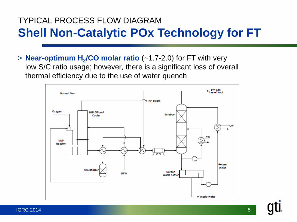
TYPICAL PROCESS FLOW DIAGRAM
Shell Non-Catalytic POx Technology for FT
> Near-optimum H2/CO molar ratio (~1.7-2.0) for FT with very
low S/C ratio usage; however, there is a significant loss of overall
thermal efficiency due to the use of water quench
IGRC 2014 6 IGRC 2014 6
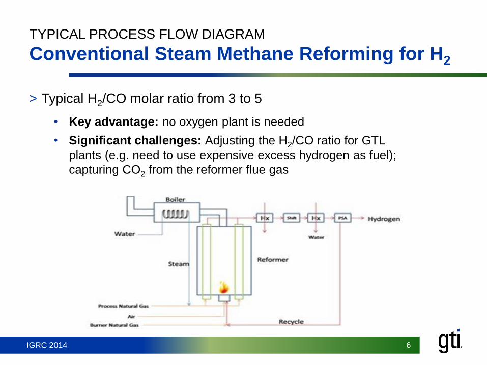
TYPICAL PROCESS FLOW DIAGRAM
Conventional Steam Methane Reforming for H2
> Typical H2/CO molar ratio from 3 to 5
• Key advantage: no oxygen plant is needed
• Significant challenges: Adjusting the H2/CO ratio for GTL
plants (e.g. need to use expensive excess hydrogen as fuel);
capturing CO2 from the reformer flue gas
IGRC 2014 7 IGRC 2014 7
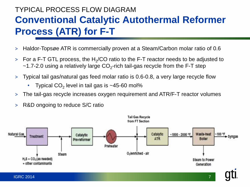
Tail Gas Recycle
from FT Section
TYPICAL PROCESS FLOW DIAGRAM
Conventional Catalytic Autothermal Reformer
Process (ATR) for F-T
> Haldor-Topsøe ATR is commercially proven at a Steam/Carbon molar ratio of 0.6
> For a F-T GTL process, the H2/CO ratio to the F-T reactor needs to be adjusted to
~1.7-2.0 using a relatively large CO2-rich tail-gas recycle from the F-T step
> Typical tail gas/natural gas feed molar ratio is 0.6-0.8, a very large recycle flow
• Typical CO2 level in tail gas is ~45-60 mol%
> The tail-gas recycle increases oxygen requirement and ATR/F-T reactor volumes
> R&D ongoing to reduce S/C ratio

IGRC 2014 8 IGRC 2014 8
Impact of Reduced Steam/Carbon Ratio
on ATR Performance
Ref. : Haldor Topsoe Data (P. K. Bakkerud, Cat. Today, 106 (2005) 30-33)
Case ATR (Base) ATR (Advanced) @
Lower S/C
Steam/Carbon Ratio 0.6 0.4
O2 Usage, tonnes/bbl Produced Index 100 92
Total LHV Efficiency, Index 100 105
Air Separation Unit CAPEX/, $/bbl/day Index 100 83
Syngas Production CAPEX, $/bbl/day Index 100 69
ASU + SGP CAPEX Index 100 76

IGRC 2014 9 IGRC 2014 9
GTI’s Process Concept using
AR Turbo-POx Technologies for GTL
> Front-end uses AR Turbo-POx technologies for improved
overall efficiency and lower liquid production costs
> Multiple backend process capability
GTI Process Example Syngas to Liquid Fuels
Typical Product
Mix, Vol%:
Gasoline: 86%
LPG : 14%
GTI Patents
7,421,835-B2
8,268,896-B2

IGRC 2014 10 IGRC 2014 10
Aerojet Rocketdyne (AR) and GTI Collaboration
– ARPA-E Program
> Pilot plant testing of AR’s non-catalytic POx reactor at GTI
• ~10 tonnes/day natural gas feed rate
• A similar reactor was used at GTI for AR’s dry-coal feed
gasification process R&D using oxygen/steam
> Design studies by AR for Turbo-POx expander
> Techno-economic assessment GTL design cases by GTI
• ~ 1,000 bbl/day FT products
• ~ 10,000 bbl/day gasoline plus LPG

IGRC 2014 11 IGRC 2014 11
AR POx Combustor Testing at GTI
> Full-flow POx combustor & injector testing at
1,000 barrels/day POGT capacity
• 12 POx combustor cans per expander anticipated
• GTI testing at 400 psia chamber pressure
> Performance mapping at four discrete
temperatures & four discrete steam/methane
ratios (16 total tests, with 4 at sooting
conditions)
> Correlation of test data with proprietary AR multi-
stream kinetics model
• Predictions of methane slip, free-stream soot
formation and effects of injector mixing efficiency
Ref.: “Partial Oxidation Gas-Turbine Based Turbo-POx Syngas Generation Technology for GTL Applications,” S. P.
Fusselman and A. Basu, GTL Technology Forum, Gulf Publishing Company, Houston, July 2014

IGRC 2014 12 IGRC 2014 12
AR Reducing-Gas Turbo-Expander
> Technology expertise from liquid rocket-engine
rotating machinery design practices
> Materials compatibility in high-temperature and high-
pressure reducing gas (i.e. syngas) environments
under high-stress loading
• Hydrogen embrittlement – generation of
detrimental metal hydrides
• Carbon monoxide (carbon dusting) embrittlement
– generation of detrimental metal carbides
> Rapid syngas quench: <6 millisecond
(Carbon soot suppression)
> Regenerative (regen) cooling of blades
• US Patent 6,565,312 (2003)
• Produces high-pressure (saturated or
superheated) steam for use in other process units
(e.g. POx combustor; auxiliary power)
Ref.: “Partial Oxidation Gas-Turbine Based Turbo-POx Syngas Generation Technology for GTL Applications,” S. P. Fusselman and
A. Basu, GTL Technology Forum, Gulf Publishing Company, Houston, July 2014

IGRC 2014 13 IGRC 2014 13
AR Expander Development
Current design sized for 1,000 barrels/day of liquids production and 6 MWe output
> Regen-cooled stator blades provide higher system efficiency than film-cooled blades
> Coolant output is 1,700 psia saturated steam (100% quality)
Ref.: “Partial Oxidation Gas-Turbine Based Turbo-POx Syngas Generation Technology for GTL Applications,” S. P. Fusselman
and A. Basu, GTL Technology Forum, Gulf Publishing Company, Houston, July 2014

IGRC 2014 14 IGRC 2014 14
Key Potential Advantages for Turbo-POx
vs. Catalytic ATR
> Close-coupled compact POx reactor and expander
• Ideal for shop fabrication and modular small-scale GTL plants
> No catalytic pre-reformer (reduced CAPEX) + no catalyst for POx
reactor (reduced OPEX)
> Significantly lower S/C ratio (e.g. 0.2 vs. 0.6 for ATR): this would
significantly reduce oxygen requirement + tail-gas recycle in a F-T
process
• Reduced volumes for POx/F-T reactors
• Reduced compression costs for Tail-gas recycle
• Reduced O2 need would lead to less power needed
> Significantly reduced capacities and lower CAPEX/OPEX costs for
waste-heat boiler (WHB), steam turbine power-generation unit and
steam systems

IGRC 2014 15 IGRC 2014 15
Comparative Data on Thermodynamic Efficiency
Basis : 13,000 kgmols/hour of Syngas
Turbo-POx + a
Smaller WHB
Conventional AR-
POx Reactor + WHB
Gross electric power generation
from Expander, MWe1
54.8 --
Electricity generated from HP
steam from WHB2
30.2 52.9
Electricity need for syngas
compression (to P : inlet of
Methanol Reactor)
(18.1)
Total, MWe 66.9 52.9
Total Electricity generated,
Relative
126 100
1 Expander outlet @ 168 psia 2 Syngas is cooled to 100 F
IGRC 2014 16 IGRC 2014 16
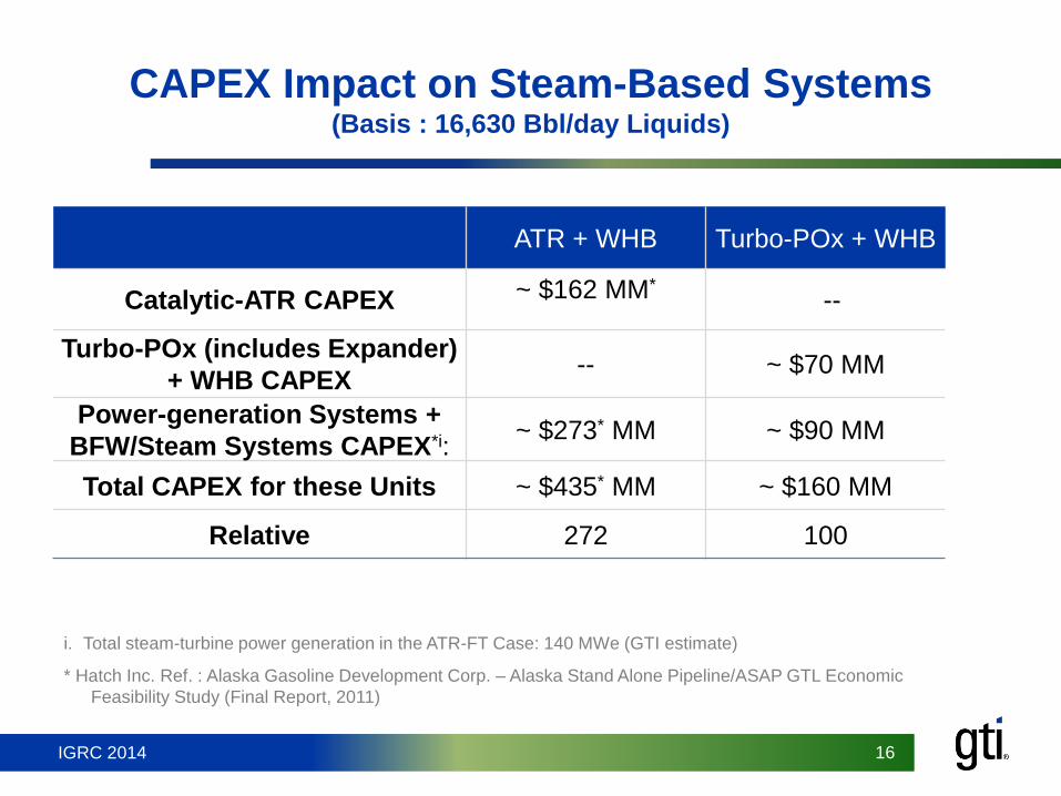
CAPEX Impact on Steam-Based Systems (Basis : 16,630 Bbl/day Liquids)
* Hatch Inc. Ref. : Alaska Gasoline Development Corp. – Alaska Stand Alone Pipeline/ASAP GTL Economic
Feasibility Study (Final Report, 2011)
ATR + WHB Turbo-POx + WHB
Catalytic-ATR CAPEX ~ $162 MM*
--
Turbo-POx (includes Expander)
+ WHB CAPEX -- ~ $70 MM
Power-generation Systems +
BFW/Steam Systems CAPEX*i: ~ $273* MM ~ $90 MM
Total CAPEX for these Units ~ $435* MM ~ $160 MM
Relative 272 100
i. Total steam-turbine power generation in the ATR-FT Case: 140 MWe (GTI estimate)

IGRC 2014 17 IGRC 2014 17
Expander and System Scale-up Challenges
> Demonstrate close-coupled POx reactor and expander
system corresponding to ~1,000 bbl/day liquids
(NG at 10 Million SCF/day) and 6 MWe power output
• Fabrication of expander system
• Demonstrate commercially attractive expander-blade life
• Demonstrate soot-free, metal-dusting free syngas
generation at low S/C ratio
IGRC 2014 18 IGRC 2014 18
Summary and Conclusions
> The AR/GTI Turbo-POx GTL plants offer potential
economic advantages compared to conventional POx and
ATR GTL processes
> The regen-cooled design needs further maturity to meet
expander life requirements in reducing syngas environment
> A 1,000 barrels/day integrated AR POx and expander unit
needs to be demonstrated at a brown-field site. Testing
should include:
• Risk mitigation of key expander components
• Expander performance mapping and long duration test
efforts

IGRC 2014 19 IGRC 2014 19
Acknowledgements
> The information, data, and work presented herein was
funded in part by the U.S. Department of Energy (DOE)
Advanced Research Projects Agency-Energy (ARPA-E)
under Award # DE-AR0000290
• However, any opinions, findings, conclusions, or
recommendations expressed herein are those of the authors and
do not necessarily reflect the views of the DOE.
> Special thanks to:
• Bryan Wilson, Program Director, U.S. DOE ARPA-E
• Ken Sprouse, Steve Fusselman and Mitul Jambusaria
of Aerojet Rocketdyne

IGRC 2014 20 IGRC 2014 20
Connect With Us
Gas Technology Institute
1700 S Mount Prospect Rd, Des Plaines, IL 60018, USA
www.gastechnology.org
Contact:
Vann Bush
Managing Director,
Energy Conversion
847-768-0973
Authors: Arun Basu, Howard Meyer,
Jim Aderhold, Bruce Bryan,
and Andrew Kramer, GTI
@gastechnology