Part Number: IM 919 Rooftop and Self-Contained...
66
© 2008 McQuay International RAH, RCS, RDS, RDT, RFS, RPS, SWP, and SWT Installation Manual IM 919 MicroTech III ® Unit Controller for Applied Rooftop and Self-Contained Systems Group: Applied Systems Part Number: IM 919 Date: October 2008
Transcript of Part Number: IM 919 Rooftop and Self-Contained...

RAH, RCS, RDS, RDT, RFS, RPS, SWP, and SWT
Installation Manual IM 919
MicroTech III® Unit Controller for Applied Rooftop and Self-Contained Systems
Group: Applied Systems
Part Number: IM 919
Date: October 2008
© 2008 McQuay International


ContentsIntroduction .............................................................. 4
General Description............................................ 5Component Data ................................................ 5Control Panel...................................................... 6Main Control Board (MCB) ................................. 8Expansion Boards A, B, C.................................. 8Dip Switch Settings for Expansion Boards ......... 9
Keypad/Display ...................................................... 10Passwords........................................................ 10Navigation Mode .............................................. 12Edit Mode ......................................................... 12
Description of Operation ....................................... 13Temperature Sensors....................................... 13Pressure Sensors............................................. 17Duct Pressure Sensor ...................................... 18Building Pressure Sensor ................................. 18Actuators .......................................................... 19
Variable Frequency Drives (VFD's)................... 19Smoke Detectors .............................................. 19
Controller Inputs/Outputs ...................................... 20Field Wiring ............................................................. 26
Field Output Signals.......................................... 26Field Analog Input Signals ................................ 28External Outdoor Air Damper Reset Signal ...... 32Humidity Sensors.............................................. 32Field Digital Input Signals ................................. 33
Cooling: Multistage ................................................ 34Compressor Staging ......................................... 34
Communication Module ......................................... 43Network Communications ................................. 43
Software Identification and Configuration ........... 44Typical Electrical Drawings - Rooftop .................. 46Typical Electrical Drawings - Self Contained....... 56Parts List ................................................................. 64
Introduction
IntroductionThis manual contains information regarding the MicroTech III® control system used in the McQuay Rooftop and Self Contained product lines. It describes the MicroTech III components, input/output configurations, field wiring options and requirements, and service procedures. For a description of operation and information on using the keypad to view data and set control parameters, refer to the appropriate operation manual. For installation and commissioning instructions and general information on a particular unit model, refer to its model-specific installation manual.Table 1: Operation, Installation and Maintenance ResourcesUnit Manual
MicroTech III Rooftop Unit Controller - BACnet IP Communications
IM 916
MicroTech III Rooftop Unit Controller - BACnet MSTP Communications
IM 917
MicroTech III Rooftop Unit Controller - BACnet LON Communications
IM 918
Rooftop/Self-Contained Operation OM 920RPS/RDT/RFS/RCS 015C-105C IM 926RPS/RDT/RFS/RCS 050D-140D IM 893SWP Self-Contained (018 to 105) IM 937
NOTICE
This equipment generates, uses, and can radiate radio frequency energy and, if not installed and used in accordance with this instruction manual, may cause interference to radio communications. It has been tested and found to comply with the limits for a Class A digital device, pursuant to part 15 of the FCC rules. These limits are designed to provide reasonable protection against harmful interference when the equipment is operated in a commercial environment. Operation of this equipment in a residential area is likely to cause harmful interference in which case the user is required to correct the interference at his own expense. McQuay International disclaims any liability resulting from any interference or for the correction thereof.
WARNING
Electric shock hazard. Can cause personal injury or equipment damage.This equipment must be properly grounded. Connections and service to the MicroTech III control panel must be performed only by personnel that are knowledgeable in the operation of the equipment being controlled.
WARNING
Excessive moisture in the control panel can cause hazardous working conditions and improper equipment operation.When servicing this equipment during rainy weather, the electrical components in the main control panel must be protected from the rain.
4 McQuay IM 919

Introduction
General DescriptionThe MicroTech III Unit Controller is a microprocessor-based controller designed to provide sophisticated control of McQuay Air Handling unit. In addition to providing normal temperature, static pressure, and ventilation control, the controller can provide alarm monitoring and alarm-specific component shutdown if critical system conditions occur.
The operator can access temperatures, pressures, operating states, alarm messages, control parameters, and schedules with the keypad/display. The controller includes password protection against unauthorized or accidental control parameter changes.
This MicroTech III controller is capable of complete, stand-alone rooftop unit control, or it can be incorporated into a building-wide network using an optional plug-in communication module. Available communication modules include BACnet/IP, BACnet MS/TP, and LONMARK.
Component DataThe main components of the MicroTech III control system include the main control board (MCB) with a built in keypad/display and I/O's, Expansion Modules A, B, C. Transformers T2, T3 and T9 supply power to the system. The following pages contain descriptions of these components and their input and output devices.
CAUTION
Extreme temperature hazard. Can cause damage to system components.The MicroTech III controller is designed to operate in ambient temperatures from -20°F to 125°F. It can be stored in ambient temperatures from -40°F to 140°F. It is designed to be stored and operated in relative humidity up to 95% (non-condensing).
CAUTION
Static sensitive components. A static discharge while handling electronic circuit boards can cause damage to the components.Discharge any static electrical charge by touching the bare metal inside the main control panel before performing any service work. Never unplug any cables, circuit board terminal blocks, relay modules, or power plugs while power is applied to the panel.
McQuay IM 919 5

Introduction
Control PanelFigure 1: Control Panel - 208 V, 36 Ton
6 McQuay IM 919

Introduction
Figure 2: Control Panel - 208 V, 68 Ton with SpeedtrolMcQuay IM 919 7

Introduction
Main Control Board (MCB)Figure 3: Main Control Board
Expansion Boards A, B, C
Figure 4: Expansion Board
8 McQuay IM 919

Introduction
Figure 5: Expansion Board Side ViewsDip Switch Settings for Expansion Boards
Figure 6: Dip Switch Settings
Expansion Board A = #5 switch in the up position (all others down)
Expansion Board B = #4 switch in the up position (all others down)
Expansion Board C = #4 & #5 switch in the up position (all others down)
Dipswitch #6 must be in the up position on the last Expansion Board in the string regardless whether it is A, B, or C.
Table 2: MCB I/O Connection LabelingMCB I/O Connection Label
T1 24 VOLT POWER SUPPLYT2 DIGITAL OUTPUT 1, T3 DIGITAL OUTPUT 2, 3, 4T4 DIGITAL OUTPUT 5, 6, 7, 8T5 DIGITAL OUTPUT 9, 10T6 DIGITAL INPUT 5, 6T7 ANALOG INPUT 1, 2, 3T8 UNIVERSAL I/O 1, 2, 3, 4T9 UNIVERSAL I/O 5, 6, 7, 8
T10 DIGITAL INPUT 1, 2T11 DIGITAL INPUT 3, 4T12 MODBUS/VFDT13 PROCESS BUS/FUTURE
McQuay IM 919 9

Keypad/Display
Keypad/Display The keypad/display consists of a 5-line by 22 character display, three keys and a “push and roll” navigation wheel. There is an Alarm Button, Menu (Home) Button, and a Back Button. The wheel is used to navigate between lines on a screen (page) and to increase and decrease changeable values when editing. Pushing the wheel acts as an Enter Button.Figure 7: Keypad/Display
The first line on each page includes the page title and the line number to which the cursor is currently “pointing”. The line numbers are X/Y to indicate line number X of a total of Y lines for that page. The left most position of the title line includes an “up” arrow to indicate there are pages "above" the currently displayed items, a "down" arrow to indicate there are pages “below” the currently displayed items or an "up/down" arrow to indicate there are pages “above and below” the currently displayed page.
Each line on a page can contain status only information or include changeable data fields. When a line contains status only information and the cursor is on that line all but the value field of that line is highlighted meaning the text is white with a black box around it. When the line contains a changeable value and the cursor is at that line, the entire line is highlighted. Each line on a page may also be defined as a “jump” line, meaning pushing the navigation wheel will cause a “jump” to a new page. An arrow is displayed to the far right of the line to indicate it is a “jump” line and the entire line is highlighted when the cursor is on that line.
The keypad/display Information is organized into five main menus or menus groups; Alarm Lists Menu, System Summary Menu, Standard Menus, Extended Menus and Advance Menus.Note – Only menus and items that are applicable to the specific unit configuration are displayed.
The Alarm Lists Menu includes active alarm and alarm log information. The System Summary Menu includes status information indicating the current operating condition of the unit. Standard Menus include basic menus and items required to setup the unit for general operation. These include such things are control mode, occupancy mode and heating and cooling setpoints. Extended Menus include more advanced items for “tuning” unit operation such as PI loop parameters and time delays. Advanced Menus include the most advanced items such as “unit configuration” parameters and service related parameters. These generally do not needing changing or accessing unless there is a fundamental change to or a problem with the unit operation.
PasswordsWhen the keypad/display is first accessed, the Home Key is pressed, the Back Key is pressed multiple times, or if the keypad/display has been idle for the Password Timeout timer (default 10 minutes), the display will show a “main” page where the user can enter a password or continue without entering a password. The three password levels available are Level 2, Level 4, and Level 6, with Level 2 having the highest level of access. Entering the Level 6 password allows access to the Alarm Lists Menu, System Summary Menu, and the Standard Menus group. Entering the Level 4 password allows similar access to Level 6 with the addition of the Extended Menus group. Entering the Level 2 password allows similar access to Level 4 with the addition of the Advanced Menus group. The Level 2 password is 6363, the Level 4 is 2526, and the Level 6 password is 5321. Continuing without entering one of these three levels allows access only to the Alarm Lists Menu and the System Summary Menu. Note – Alarms can be acknowledged without entering a password.
3/23System Summary
Advanced MenusAlarm Lists
Unit State= CoolingClg Capacity= 25%
10 McQuay IM 919

Keypad/Display
Figure 8: Password Main PageThe password field initially has a value **** where each * represents an adjustable field. These values can be changed by entering the Edit Mode described below.
Figure 9: Password Entry Page
Entering an invalid password has the same effect as continuing without entering a password.
Once a valid password has been entered, the controller allows further changes and access without requiring the user to enter a password until either the password timer expires or a different password is entered. The default value for this password timer is 10 minutes. It is changeable from 3 to 30 minutes via the Timer Settings menu in the Extended Menus.
1/3McQuay AHU
Enter PasswordContinue W/O PasswordVersion Information
1/1Enter Password
Enter Password ****
McQuay IM 919 11

Keypad/Display
Navigation ModeIn the Navigation Mode, when a line on a page contains no editable fields all but the value field of that line is highlighted meaning the text is white with a black box around it. When the line contains an editable value field the entire line is inverted when the cursor is pointing to that line.When the navigation wheel is turned clockwise, the cursor moves to the next line (down) on the page. When the wheel is turned counter-clockwise the cursor moves to the previous line (up) on the page. The faster the wheel is turned the faster the cursor moves.
When the Back Button is pressed the display reverts back to the previously displayed page. If the Back button is repeated pressed the display continues to revert one page back along the current navigation path until the “main menu” is reached.
When the Menu (Home) Button is pressed the display reverts to the “main page”.
When the Alarm Button is depressed, the Alarm Lists menu is displayed.
Edit ModeThe Editing Mode is entered by pressing the navigation wheel while the cursor is pointing to a line containing an editable field. Once in the edit mode pressing the wheel again causes the editable field to be highlighted. Turning the wheel clockwise while the editable field is highlighted causes the value to be increased. Turning the wheel counter-clockwise while the editable field is highlighted causes the value to be decreased. The faster the wheel is turned the faster the value is increased or decreased. Pressing the wheel again cause the new value to be saved and the keypad/display to leave the edit mode and return to the navigation mode.
12 McQuay IM 919

Description of Operation
Description of OperationTemperature SensorsThe MicroTech III controller uses passive negative temperature coefficient (NTC) 10K ohm sensors. These sensors vary their input resistance to the MCB as the temperature changes.Figure 10: Input Resistance
McQuay IM 919 13

Description of Operation
Figure 11: Input Resistance (continued)14 McQuay IM 919

Description of Operation
Figure 12: Input Resistance (continued)McQuay IM 919 15

Description of Operation
Figure 13: DAT, RAT, OAT, and EFT Sensor WiringFigure 14: MAT and EWT Sensor Wiring
Figure 15: LAT and EAT Sensor Wiring
16 McQuay IM 919

Description of Operation
Pressure SensorsThe MicroTech III controller uses 0 to 5" W.C. static pressure transducers for measuring duct static pressure. As the duct static pressure varies from 0-5" W.C., the transducer output will vary from 4-20mA. The transducer output signal is 4-20mA however the signal entering the VFD is converted to a DC signal via a 500 Ohm resistor across the output signal at the transducer.If building static pressure control is provided, a -0.25" W.C. to 0.25" W.C. static pressure transducer is used. As the building static pressure varies from -0.25" W.C. to 0.25" W.C., the transducer output will vary from 4-20mA. The transducer output signal is 4-20mA however the signal entering the VFD is converted to a DC signal via a 500 Ohm resistor across the output signal at the transducer.
Troubleshooting Pressure TransducersIf the duct static pressure always reads 0" WC on the unit keypad/display and the VFD speed is continuously ramping to 100%, check the following:
If the unit has two duct static pressure sensors (SPS1 and SPS2), verify that they both function properly per the following procedure. Also check for faulty wiring connections at the VFD analog inputs.
The controller displays and controls to the lower of the two readings. If a sensor is defective and inputs 0 volts to the VFD, the static pressure reading on the keypad/display reads 0 and the controller attempts to increase the 0 value to set point by ramping the VFD up.
If a second sensor (SPS2) is not installed or the pressure tubing to it is not connected, make sure the 2nd DSP Sensor= parameter in the Unit Configuration menu of the keypad/display is set to “No” so that the controller ignores the second static pressure analog input.
If a second sensor (SPS2) is installed, make sure the 2nd DSP Sensor= parameter in the Unit Configuration menu of the keypad/display is set to “Yes”.
Check the 24 VDC power supply to the sensor, verify that there is 24 VDC between the suspect transducer “+” and “-” terminals.
Using an accurate manometer or gauge, measure the same pressure that the suspect transducer is sensing. To do this, tap into the transducer high and low pressure tubing or locate the measurement device taps next to the transducer taps.
If the suspect sensor is measuring duct static pressure, verify that the high and low pressure taps are properly installed. An improper pressure tap installation can cause severe fluctuations in the sensed pressure. Refer to the model-specific installation manual for pressure tap installation guidelines.
Measure the DC voltage output from the transducer across the sensor “S” and “-” terminals.
If the measured voltage and pressure do not match, there may be a wiring problem, the factory 500 ohm resistor across “S” and “-” or the transducer may be defective. Check the transducer input circuit wiring and connections for defects. If the measured voltage and pressure match, the VFD parameters and/or ModBus communication between the controller and the VFD will need to be verified.
Remove powers from the controller by opening system switch S1. If available, swap a similar good transducer with the suspect transducer or try installing a new transducer. Restore power by closing S1 and verify whether the suspect transducer is defective.
McQuay IM 919 17

Description of Operation
Duct Pressure SensorInput Voltage - 24 VDC
Output - 4-20 mANote – The transducer output signal is 4-20mA however the signal entering the VFD is converted
to a DC signal via a 500 Ohm resistor across the output signal(“S” and “-”).
Figure 16: Duct Pressure Sensor
Building Pressure Sensor
Input Voltage - 24 VDC
Output - 4-20 mANote – The transducer output signal is 4-20mA however the signal entering the VFD is converted
to a DC signal via a 500 Ohm resistor across the output signal(“S” and “-”).
Figure 17: Building Pressure Sensor
18 McQuay IM 919
Description of Operation
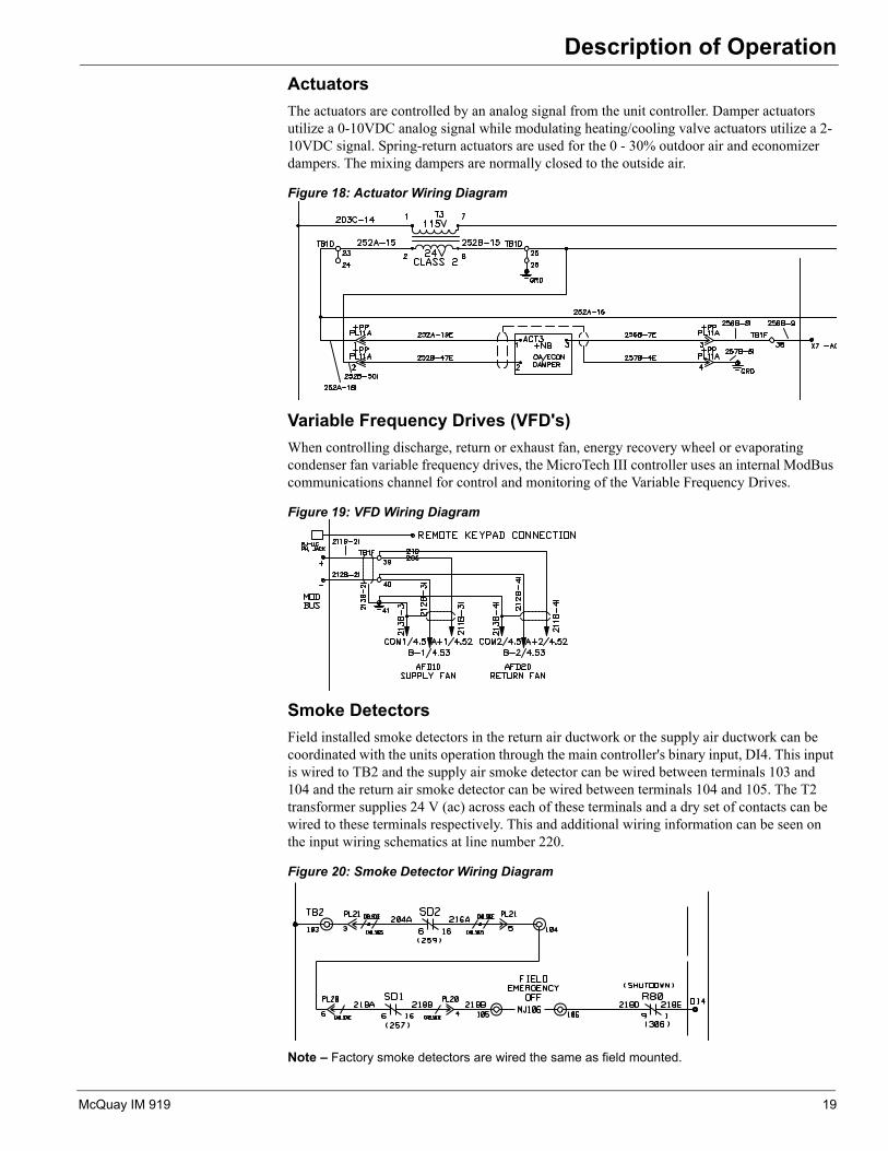
ActuatorsThe actuators are controlled by an analog signal from the unit controller. Damper actuators utilize a 0-10VDC analog signal while modulating heating/cooling valve actuators utilize a 2-10VDC signal. Spring-return actuators are used for the 0 - 30% outdoor air and economizer dampers. The mixing dampers are normally closed to the outside air.Figure 18: Actuator Wiring Diagram
Variable Frequency Drives (VFD's)When controlling discharge, return or exhaust fan, energy recovery wheel or evaporating condenser fan variable frequency drives, the MicroTech III controller uses an internal ModBus communications channel for control and monitoring of the Variable Frequency Drives.
Figure 19: VFD Wiring Diagram
Smoke DetectorsField installed smoke detectors in the return air ductwork or the supply air ductwork can be coordinated with the units operation through the main controller's binary input, DI4. This input is wired to TB2 and the supply air smoke detector can be wired between terminals 103 and 104 and the return air smoke detector can be wired between terminals 104 and 105. The T2 transformer supplies 24 V (ac) across each of these terminals and a dry set of contacts can be wired to these terminals respectively. This and additional wiring information can be seen on the input wiring schematics at line number 220.
Figure 20: Smoke Detector Wiring Diagram
Note – Factory smoke detectors are wired the same as field mounted.
McQuay IM 919 19

Controller Inputs/Outputs
Controller Inputs/OutputsTable 3: Controller and Expansion Board I/ONote – When used for LP1 and LP2, LP1 is considered Closed when resistance value is 0-799 or 1250-1800. Otherwise LP1 is considered Open. LP2 is considered Closed when the resistance value is 0-1249, otherwise LP2 is considered Open.
Note – Enthalpy switch is considered Closed when resistance value is 0-799 or 1250-1800. Otherwise it is considered Open. Freezestat is considered Closed when the resistance value is 0-1249, otherwise it is considered Open.
PolyCool 600 Main Controller - RTUAnalog Inputs – 10K NTC
# Point CommentsAI 1 Discharge Temperature 10K ThermistorAI 2 Return Temperature 10K ThermistorAI 3 Outdoor Temperature 10K Thermistor
Universal Inputs/Outputs# DI AI DO AO Point Comments
X1 X CO2 / Min OA 0-10VDC or 4-20 mAX 2 X X Low Pressure 1 and
2/Chilled Wtr11K & 2K Ohm Input/0-10 VDC
X 3 X Space Temperature 10K ThermistorX 4 X Zone Setpoint or DAT Reset .5 – 1.5 kOhm or 0-10VDC/4-
20mAX 5 X Enthalpy&Freeze Sw2 1K & 1.5K Ohm InputX 6 X Ent Fan & Lvg Coil T 10K Thermistor - Gas or Electric
Heat & DehumX 7 X OA Damper 0-10 VDCX 8
Digital Inputs – Dry Contacts# Point Comments
DI 1 Air Flow Switch Dry ContactDI 2 Filter Switch Dry Contact
Digital Inputs – 24V# Point Comments
DI 3 Remote Start / Stop External 24VDI 4 Emergency Off External 24V
Digital Inputs – 115 V# Point Comments
DI 5 High Pressure 1 115 VAC InputDI 6 High Pressure 2 115 VAC Input
Digital Outputs – Relay (SPST, Normally Open, 230 VAC 3 Amp# Point Comments
DO 1 Compressor 1DO 2 Compressor 3DO 3 Compressor 2DO 4 Compressor 4 DO 5 Supply FanDO 6DO 7 Cond Fan Output A/ Generic Comp 7 2 Relays, CF3 & CF4DO 8 Cond Fan Output B/ Generic Comp 8 2 Relays, CF5 & CF6
Digital Outputs – Solid State Relays, 24-230 VAC, .5 ADO 9 Alarm
DO 10 Fan Operation / VAV Box Output
20 McQuay IM 919
Controller Inputs/Outputs
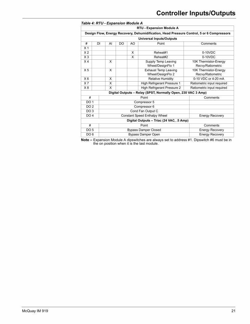
Table 4: RTU - Expansion Module ANote – Expansion Module A dipswitches are always set to address #1. Dipswitch #6 must be in the on position when it is the last module.
RTU - Expansion Module ADesign Flow, Energy Recovery, Dehumidification, Head Pressure Control, 5 or 6 Compressors
Universal Inputs/Outputs# DI AI DO AO Point Comments
X 1X 2 X Reheat#1 0-10VDCX 3 X Reheat#2 0-10VDCX 4 X Supply Temp Leaving
Wheel/DesignFlo 110K Thermistor-Energy
Recvy/RatiometricX 5 X Exhaust Temp Leaving
Wheel/DesignFlo 210K Thermistor-Energy
Recvy/RatiometricX 6 X Relative Humidity 0-10 VDC or 4-20 mAX 7 X High Refrigerant Pressure 1 Ratiometric input requiredX 8 X High Refrigerant Pressure 2 Ratiometric input required
Digital Outputs – Relay (SPST, Normally Open, 230 VAC 3 Amp)# Point Comments
DO 1 Compressor 5DO 2 Compressor 6 DO 3 Cond Fan Output CDO 4 Constant Speed Enthalpy Wheel Energy Recovery
Digital Outputs – Triac (24 VAC, .5 Amp)# Point Comments
DO 5 Bypass Damper Closed Energy RecoveryDO 6 Bypass Damper Open Energy Recovery
McQuay IM 919 21

Controller Inputs/Outputs
Table 5: RTU - Expansion Module BNote – Expansion Module B dipswitches are always set to address #2. Dipswitch #6 must be in the on position when it is the last module.
Table 6: RTU - Expansion Module C
Note – Expansion Module C dipswitches are always set to address #3. Dipswitch #6 must be in the on position when it is the last module.
RTU - Expansion Module BStaged Heat, F&BP Dampers
Universal Inputs/Outputs# DI AI DO AO Point Comments
X 1 X Gas Heat Purge Enable (FSG4) Dry ContactX 2 X Gas Heat LS1 Switch Dry ContactX 3 X Gas heat LS2 Switch Dry ContactX 4X 5X 6X 7 X Heating Valve 2-10 VDC/0-10 VDCX 8 X F&BP Damper 0-10 VDC
Digital Outputs – Relay (SPST, Normally Open, 230 VAC 3 Amp)# Point Comments
DO 1 Gas Heat (On/Off)/Heat Stage 1DO 2 Gas Heat (On/Off) Heat Stage 2DO 3 Heat Stage 3DO 4 Heat Stage 4
Digital Outputs – Triac (24 VAC, .5 Amp)# Point Comments
DO 5 Heat Stage 5DO 6 Heat Stage 6
RTU - Expansion Module CEvaporative CondensingUniversal Inputs/Outputs
# DI AI DO AO Point CommentsX 1X 2X 3 X Sump Temperature 10K Thermistor- Evaporative
CondensingX 4 X Conductivity 4-20 mA -Evaporative
CondensingX 5X 6X 7X 8 X Sump Pump Status Dry Contact
Digital Outputs – Relay (SPST, Normally Open, 230 VAC 3 Amp)# Point Comments
DO 1DO 2 Drain Valve Evaporative CondensingDO 3 Sump Pump Evaporative CondensingDO 4
Digital Outputs – Triac (24 VAC, .5 Amp)# Point Comments
DO 5DO 6
22 McQuay IM 919

Controller Inputs/Outputs
Table 7: PolyCool 600 Main Controller - SCUNote – When used for LP1 and LP2, LP1 is considered Closed when resistance value is 0-799 or 1250-1800. Otherwise LP1 is considered Open. LP2 is considered Closed when the resistance value is 0-1249, otherwise LP2 is considered Open.
Note – Enthalpy switch is considered Closed when resistance value is 0-799 or 1250-1800. Otherwise it is considered Open. Freezestat is considered Closed when the resistance value is 0-1249, otherwise it is considered Open.
PolyCool 600 Main Controller - SCUAnalog Inputs – 10K NTC
# Point CommentsAI 1 Discharge Temperature 10K ThermistorAI 2 Return Temperature 10K ThermistorAI 3 Outdoor Temperature 10K Thermistor
Universal Inputs/Outputs# DI AI DO AO Point Comments
X1 X Entering WaterTemperature 10K ThermistorX 2 X Low Pressure 1 & 2/Chilled
Wtr11K & 2K Ohm Input/0-10 VDC
X 3 X Space Temperature 10K ThermistorX 4 X Zone Setpoint or DAT Reset .5 – 1.5 kOhm or 0-10VDC/4-
20mA X 5 X Enthalpy & Freeze Sw2 1K & 2K Ohm InputX 6 X Bypass/Water Regulating
Valve0 – 10 VDC
X 7 X Economizer 0 – 10 VDCX 8 X Mixed Air Temp 10K Thermistor
Digital Inputs – Dry Contacts# Point Comments
DI 1 Air Flow Switch Dry ContactDI 2 Filter Switch Dry Contact
Digital Inputs – 24V# Point Comments
DI 3 Remote Start / Stop External 24VDI 4 Emergency Off External 24V
Digital Inputs – 115V# Point Comments
DI 5 High Pressure 1 115 VAC InputDI 6 High Pressure 2 115 VAC Input
Digital Outputs – Relay (SPST, Normally Open, 230 VAC 3 Amp# Point Comments
DO 1 Compressor 1DO 2 Compressor 3DO 3 Compressor 2DO 4 Compressor 4 DO 5 Supply FanDO 6DO 7 Outdoor Damper Open/CloseDO 8 Pump On/Off
Digital Outputs – Solid State Relays, 24-230 VAC, .5 ADO 9 Alarm
DO 10 Fan Operation / VAV Box Output
McQuay IM 919 23
Controller Inputs/Outputs
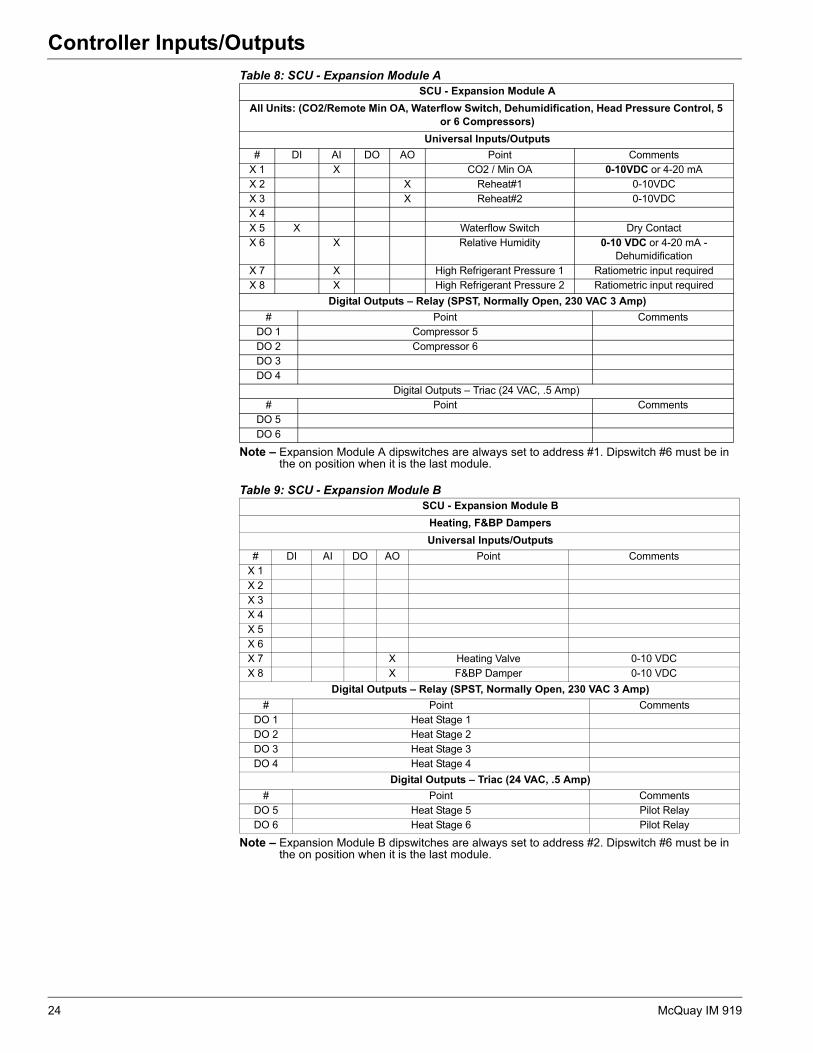
Table 8: SCU - Expansion Module ANote – Expansion Module A dipswitches are always set to address #1. Dipswitch #6 must be in the on position when it is the last module.
Table 9: SCU - Expansion Module B
Note – Expansion Module B dipswitches are always set to address #2. Dipswitch #6 must be in the on position when it is the last module.
SCU - Expansion Module AAll Units: (CO2/Remote Min OA, Waterflow Switch, Dehumidification, Head Pressure Control, 5
or 6 Compressors)Universal Inputs/Outputs
# DI AI DO AO Point CommentsX 1 X CO2 / Min OA 0-10VDC or 4-20 mAX 2 X Reheat#1 0-10VDCX 3 X Reheat#2 0-10VDCX 4X 5 X Waterflow Switch Dry ContactX 6 X Relative Humidity 0-10 VDC or 4-20 mA -
DehumidificationX 7 X High Refrigerant Pressure 1 Ratiometric input requiredX 8 X High Refrigerant Pressure 2 Ratiometric input required
Digital Outputs – Relay (SPST, Normally Open, 230 VAC 3 Amp)# Point Comments
DO 1 Compressor 5DO 2 Compressor 6 DO 3DO 4
Digital Outputs – Triac (24 VAC, .5 Amp)# Point Comments
DO 5DO 6
SCU - Expansion Module BHeating, F&BP DampersUniversal Inputs/Outputs
# DI AI DO AO Point CommentsX 1X 2X 3X 4X 5X 6X 7 X Heating Valve 0-10 VDC X 8 X F&BP Damper 0-10 VDC
Digital Outputs – Relay (SPST, Normally Open, 230 VAC 3 Amp)# Point Comments
DO 1 Heat Stage 1DO 2 Heat Stage 2DO 3 Heat Stage 3DO 4 Heat Stage 4
Digital Outputs – Triac (24 VAC, .5 Amp)# Point Comments
DO 5 Heat Stage 5 Pilot RelayDO 6 Heat Stage 6 Pilot Relay
24 McQuay IM 919

Controller Inputs/Outputs
Table 10: SCU - Expansion Module CNote – Expansion Module C dipswitches are always set to address #3. Dipswitch #6 must be in the on position when it is the last module.
SCU - Expansion Module COne Compressor Per Circuit
Universal Inputs/Outputs# DI AI DO AO Point Comments
X 1 X Low Pressure 3 Dry ContactX 2 X Low Pressure 4 Dry ContactX 3 X High Pressure 3 Dry ContactX 4 X High Pressure 4 Dry ContactX 5 X Low Pressure 5 Dry ContactX 6 X Low Pressure 6 Dry ContactX 7 X High Pressure 5 Dry ContactX 8 X High Pressure 6 Dry Contact
Digital Outputs – Relay (SPST, Normally Open, 230 VAC 3 Amp)# Point Comments
DO 1DO 2DO 3DO 4
Digital Outputs – Triac (24 VAC, .5 Amp)# Point Comments
DO 5DO 6
McQuay IM 919 25

Field Wiring
Field Wiring Below are descriptions of the various options and features that may require field wiring to the MicroTech III controller. Refer to the job plans and specifications and the as-built wiring schematics for information regarding the specific unit.Field Output SignalsThe following outputs may be available for field connections to a suitable device.
Remote Alarm OutputThe Remote Alarm Output (MCB-DO9) supplies 24 VAC to terminal 115 on the field terminal block (TB2) when the output is on. To use this signal, wire the coil of a field supplied and installed 24 VAC pilot relay across terminals 115 and 117 on TB2. When this output is on, 24 VAC is supplied from the T3 control transformer through the output relay to energize the field relay. Refer to the as-built wiring diagrams.
The digital alarm output indicates the alarm group that contains the highest priority active alarm. This output (MCB-DO9) is On when no alarms are active. The options for the action of this output when an alarm in a group occurs are On, Fast Blink, Slow Blink, or Off. These can be edited via the Alarm Out Config menu in the Extended menus on keypad/display. The default values for the three groups of alarms are:
Warnings - Off
Problems - Slow Blink
Faults - Fast Blink
A user could eliminate any signal of a particular group of alarms through this output by selecting On for that alarm group in the keypad/display.
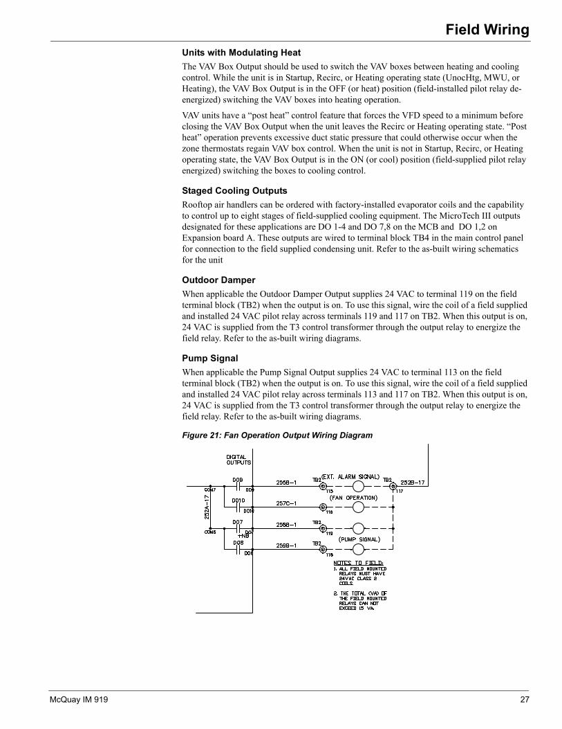
Fan OperationThe Fan Operation Output (MCB-DO10) supplies 24 VAC to terminal 116 on the field terminal block (TB2) when the output is on. To use this signal, wire the coil of a field supplied and installed 24 VAC pilot relay across terminals 116 and 117 on TB2. When this output is on, 24 VAC is supplied from the T3 control transformer through the output relay to energize the field relay. Refer to the as-built wiring diagrams.
The Fan Operation output is on when the unit is not Off and when both the unit is Off and airflow is detected. It is off when the unit is off and airflow is not detected.
Cooling Only UnitsFor cooling only VAV systems, the VAV Box Output can override zone thermostat control and drive the VAV boxes fully open to facilitate air circulation during the Recirc operating state. During this time, the VAV Box Output is in the OFF (or heat) position (field-installed pilot relay de-energized). VAV units have a “post heat” control feature that forces the VFD speed to a minimum before turning on the VAV Box Output when the Recirc operating state is complete. Post heat operation prevents excessive duct static pressure that could otherwise occur when the zone thermostats regain VAV box control. The setting of a “post heat” timer determines the duration of post heat operation. This timer is set to zero at the factory and must be set to a non-zero value to enable the “post heat” function.
26 McQuay IM 919
Field Wiring
Units with Modulating HeatThe VAV Box Output should be used to switch the VAV boxes between heating and cooling control. While the unit is in Startup, Recirc, or Heating operating state (UnocHtg, MWU, or Heating), the VAV Box Output is in the OFF (or heat) position (field-installed pilot relay de-energized) switching the VAV boxes into heating operation.VAV units have a “post heat” control feature that forces the VFD speed to a minimum before closing the VAV Box Output when the unit leaves the Recirc or Heating operating state. “Post heat” operation prevents excessive duct static pressure that could otherwise occur when the zone thermostats regain VAV box control. When the unit is not in Startup, Recirc, or Heating operating state, the VAV Box Output is in the ON (or cool) position (field-supplied pilot relay energized) switching the boxes to cooling control.
Staged Cooling OutputsRooftop air handlers can be ordered with factory-installed evaporator coils and the capability to control up to eight stages of field-supplied cooling equipment. The MicroTech III outputs designated for these applications are DO 1-4 and DO 7,8 on the MCB and DO 1,2 on Expansion board A. These outputs are wired to terminal block TB4 in the main control panel for connection to the field supplied condensing unit. Refer to the as-built wiring schematics for the unit
Outdoor DamperWhen applicable the Outdoor Damper Output supplies 24 VAC to terminal 119 on the field terminal block (TB2) when the output is on. To use this signal, wire the coil of a field supplied and installed 24 VAC pilot relay across terminals 119 and 117 on TB2. When this output is on, 24 VAC is supplied from the T3 control transformer through the output relay to energize the field relay. Refer to the as-built wiring diagrams.
Pump SignalWhen applicable the Pump Signal Output supplies 24 VAC to terminal 113 on the field terminal block (TB2) when the output is on. To use this signal, wire the coil of a field supplied and installed 24 VAC pilot relay across terminals 113 and 117 on TB2. When this output is on, 24 VAC is supplied from the T3 control transformer through the output relay to energize the field relay. Refer to the as-built wiring diagrams.
Figure 21: Fan Operation Output Wiring Diagram
McQuay IM 919 27

Field Wiring
Field Analog Input SignalsThe following inputs may be available for field connections to a suitable device.Zone Temperature Sensor PackagesA zone temperature sensor (ZNT1) is optional for all units except for the 100% outdoor air CAV-ZTC unit in which case one is required. In all unit configurations, however, a zone temperature sensor is required to take advantage of any of the following standard controller features:• Unoccupied heating or cooling• Pre-occupancy purge• Discharge air reset based on space temperature (DAC units only)• Remote timed tenant override• Remote set point adjustment (CAV-ZTC units only)
A Zone Setpoint Source (TstatSptSrc=No/Yes) parameter is provided on the keypad/display to allow for setting the setpoint via the zone thermostat input. The menu is located in the Zone Temp Setup menu of the Extended Menu section. When TstatSptSrc=No, the Zone Cooling Spt and the Zone Heating Spt may be set through the keypad or via a network signal (all units). In this case these setpoints are changed whenever the network or keypad value changes. When TstatSptSrc=Yes these setpoints can only be adjusted through the zone thermostat (zone control units). Heating and cooling setpoints must not overlap. The Zone Heating Spt must be equal to or less than the Zone Cooling Spt. If a conflict occurs from values entered via the keypad or network, the Zone Heating Spt is automatically adjusted down to eliminate the conflict.
When TstatSptSrc=No, the Zone Heating and Cooling setpoints may be changed manually by changing the setpoint displayed on the keypad.
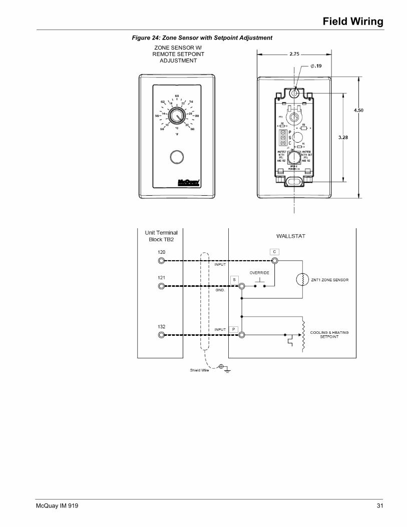
When TstatSptSrc=Yes, the Zone Cooling Setpoint is set through a setpoint adjustment included with a wall mounted space sensor. When the Zone Cooling Setpoint is changed by more than 0.5 degrees through the wall mounted sensor, the Zone Heating Setpoint is raised or lowered the same amount so that the difference between the Cooling (ZnClgSpt) and Heating (ZnHtgSpt) setpoints does not change. The setpoint adjustment is a resistance value that varies from 5000 ohm to 15000 ohms.
Figure 22: MicroTech III Wallstat Resistance vs. Setpoint
0
2000
4000
6000
8000
10000
12000
14000
16000
45 50 55 60 65 70 75 80 85
Setpoint (F)
()
Series1
28 McQuay IM 919

Field Wiring
Zone Sensor w/o Remote Set Point AdjustmentThe standard MicroTech III room temperature sensor package that does not include set point adjustment can be used with any applied rooftop MicroTech III control configuration. It includes a tenant override button. This zone sensor must be field installed and field-wired to the unit using twisted pair, shielded cable (Belden 8761 or equivalent).
Zone Sensor with Remote Set Point AdjustmentThe standard MicroTech III room temperature sensor package equipped with a set point adjustment potentiometer is available to use with CAV-ZTC units. This sensor package also includes a tenant override button. This zone sensor package must be field installed and field wired to the unit using twisted, shielded cable. Four conductors with a shield wire are required. Cable with 22 AWG conductors (Belden 8761 or equivalent) is sufficient.
Tenant Override (Timed)The tenant override button provided with the two optional zone temperature sensor packages can be used to override unoccupied operation for a programmed time period. This time period is adjustable between 0 and 5 hours using the Tenant Override parameter in the Timer Settings menu in the Extended Menus of the keypad/display (default is 2 hours). Except for the fact that it is temporary, tenant override operation is identical to occupied operation. Pressing and releasing the push button switch on the sensor momentarily shorts zone temperature sensor ZNT1, resetting and starting the override timer. The unit then starts up and runs until the override timer times out.Note – Note: Hold the button in for at least 1 second but not more than 30 seconds
Resistance vs. Temperature for Setpoint Adjustment on the MT III
Ohms T (°F) T (°C)
5000 50 10
6000 54 12
7000 57 14
8000 61 16
9000 64 18
10000 68 20
11000 72 22
12000 75 24
13000 79 26
14000 82 28
15000 86 30
McQuay IM 919 29

Field Wiring
Figure 23: Zone Sensor without Setpoint AdjustmentZONE SENSOR W/O REMOTE SETPOINT
ADJUSTMENT
30 McQuay IM 919
Field Wiring
Figure 24: Zone Sensor with Setpoint Adjustment ZONE SENSOR W/REMOTE SETPOINT ADJUSTMENT
C
S
P
McQuay IM 919 31

Field Wiring
External Outdoor Air Damper Reset SignalOn units equipped with a 0-100% modulating economizer the minimum outside air damper position set point can be reset by an external voltage or current signal. The external reset method can be selected with the Min OA Reset parameter in the Min OA Damper menu in the Standard Menus via the controller keypad/display. External reset requires a field supplied reset signal in the range of 0-10 VDC or 0-20 mA wired to terminals 124 and 125 on the field terminal block (TB2). Refer to the unit wiring diagrams for wiring termination details. If the external reset option is selected, the controller linearly resets the outside air damper position set point between user-programmed minimum (Demand Control Ventilation Limit) and maximum (Ventilation Limit) values as the field supplied reset signal varies between a minimum and maximum (or maximum to minimum) value. The external reset signal must be field-wired to the unit using a twisted pair, shielded cable (Belden 8761 or equivalent). Cable with 22 AWG conductors is sufficient.Figure 25: External Outdoor Air Damper Reset Signal Wiring Diagram
Humidity SensorsEither a wall mount or duct mount Humidity sensor is available. The sensor must be wired to terminals 126, 127 and 131 on the unit field terminal block (TB2). Terminal 126 is wired to OUT, terminal 127 to COM and terminal 131 to IN on the humidity sensor. These terminals are factory wired to the Expansion Board A AIX6. The sensor can deliver 0-10VDC or 0- 20mA, the type of signal (VDC or mA) and the 0% and 100% RH values are adjustable via the Dehum Setup menu in the Extended Menu on the keypad/display.
Figure 26: Humidity Sensor Wiring Diagram
32 McQuay IM 919

Field Wiring
Field Digital Input SignalsThe following inputs may be available for field connections to a suitable device.External Time Clock or Tenant OverrideThere are several methods of switching the rooftop unit between occupied and unoccupied operation. It can be done by the controller internal schedule, a network schedule, an external time clock, or a tenant override switch.
If the internal schedule or a network schedule is used, field wiring is not required.
An external time clock or a tenant override switch can be used by installing a set of dry contacts across terminals 101 and 102 on the field terminal block (TB2). When these contacts close, 24 VAC is applied to binary input MCB-DI3, overriding any internal or network schedule and placing the unit into occupied operation (provided the unit is not manually disabled). When the contacts open (24 VAC is removed from MCB-DI3) the unit acts according to the controller internal time schedule or a network schedule. Refer to the unit wiring diagrams for specific wiring termination details.
Figure 27: Time Clock/Tenant Override Wiring Diagram
Emergency Shutdown The terminals 105 & 106 on TB2 can be used for any field supplied component that requires a unit emergency shutdown. When these terminals are used, the factory installed jumper must be removed.
Figure 28: Emergency Shutdown Wiring Diagram
McQuay IM 919 33

Cooling: Multistage
Cooling: MultistageCompressor StagingThe staging sequences named Std-1 through Std-6 or Alt-1 through Alt-6 in the tables below indicate what compressors will be on when cooling stage is set to each stage. A single staging sequence will be active at any one time. The method for deciding which staging sequence is active is described for each compressor configuration below.Two Unequal Sized Compressors, Two Circuits, Three StagesOnly one sequence is provided so the user makes no selections.• Total cooling stages is 3.• If neither circuit is disabled, Maximum Cooling stages is set to 3. • If circuit 2 is disabled, Maximum Cooling stages is set to 1.• If circuit 1 is disabled, Maximum Cooling stages is set to 2. • If circuit is disabled, it is not re-enabled until the stage timer clears.
Two Small Comps on Circuit # 1, One Large Comp on Circuit # 2, Four StagesOnly one sequence is provided so the user makes no selections.• Total cooling stages is set to 4.• If neither circuit is disabled, the staging sequence is Std-1 if compressor # 1 has fewer hours
than compressor # 3, and the staging sequence is Std-2 if compressor # 1 does not have fewer hours than compressor # 3.
• Maximum cooling stages is set to 4. • If Circuit #1 is disabled, the staging sequence is set to Alt-1 after the stage timer, unless
Comp #2 is already on. Then the switch to Alt-1 happens immediately. Maximum cooling stages is set to 1.
• If Circuit #2 is disabled, the staging sequence is set to Std-1 if comp #1 has fewer hours than comp #3, and the staging sequence is set to Std-2 if comp #1 does not have fewer hours than comp #3, after the stage time. Maximum cooling stages is set to 2.
• Any comp on a disabled circuit stays off if it is already off and is turned off if it is on.• The staging sequence is changed based on Run Time only when the number of stages stage
is zero or Maximum cooling stages. This means that disabling and re-enabling the compressors or turning the unit off and on may be necessary to cause sequence changes.
• Alt-1 is used if circuit # 1 is disabled. • If a circuit is disabled, Maximum cooling stages is set to 2.
Table 11: Standard StagingStandard Staging
Staging Sequence Stage 1 Compressor Stage 2 Compressors Stage 3 CompressorsStd-1 1 2 1,2
StgdClgCap 33% 67% 100%
Table 12: Standard StagingStandard Staging
Staging Sequence Stage 1Compressor
Stage 2Compressors
Stage 3Compressors
Stage 4 Compressors
Std-1 1 1,3 2,3 1,2,3Std-2 3 3,1 1,2 1,2,3
StgdClgCap 25% 50% 75% 100%
34 McQuay IM 919

Cooling: Multistage
Two Equal Sized Compressors, Two CircuitsThe user selects the following:• Lead Circuit = Auto, # 1 or # 2.• A separate alternate circuit is not provided for this configuration• Total cooling stages = 2• If Lead Circuit is set to Auto and neither circuit is disabled, the compressor sequence is Std-
1 if compressor # 1 has fewer hours than compressor # 2, and the staging sequence is Std-2 if compressor # 1 does not have fewer hours than compressor # 2. Maximum cooling stages is set to 2.
• If Lead Circuit is set to # 1 or Circuit # 2 is disabled, sequence Std-1 is used. • If Lead Circuit is set to # 2 or Circuit # 1 is disabled, sequence Std-2 is used.• The Compressor Sequence changes only when the compressor stage is Maximum cooling
stages or zero. This means that disabling and re-enabling the compressors or turning the unit off and on may be necessary to cause sequence changes.
• If a circuit is disabled, Maximum cooling is set to one. The compressor on the disabled circuit stays off if it is already off and is turned off if it is on.
Three Equal Sized Compressors, Three Circuits, No WRV• Total cooling stages = 3• Maximum cooling stages is always set to 3. • The Staging sequence is the Standard sequence that contains the enabled Stage 1
Compressor with the fewest run hours. Compressors in disabled circuits are ignored when only enabled compressor run hours are compared.
• The Compressor Sequence changes only when the compressor stage is Maximum cooling stages or zero. This means that disabling and re-enabling the compressors or turning the unit off and on may be necessary to cause sequence changes.
• The same staging sequence is used whether a circuit is disabled or not. This means that units will remain at a stage for an extra stage time when staging up if a disabled circuit is added at that stage. It also means that units will remain at a stage for an extra stage time when staging down if a disabled circuit is turned off at that stage.
• Any compressor on the disabled circuit stays off if it is already off and is turned off if it is on.
Table 13: Alternate StagingAlternate Circuit Staging
Staging Sequence Stage 1Compressor
Stage 2Compressors
Stage 3Compressors
Stage 4 Compressors
Alt-1 0 2 1,2 1,2,3StgdClgCap 0% 50% 75% 100%
Table 14: Standard StagingStandard Staging
Staging Sequence Stage 1 Compressor Stage 2 CompressorsStd-1 1 1,2Std-2 2 1,2
StgdClgCap 50% 100%
Table 15: Standard StagingStandard Staging
Staging Sequence Stage 1 Compressor Stage 2 Compressors Stage 3 CompressorsStd-1 1 1,2 1,2,3Std-2 2 2,3 1,2,3Std-3 3 1,3 1,2,3
StgdClgCap 33% 67% 100%
McQuay IM 919 35

Cooling: Multistage
Three Equal Sized Compressors, Three Circuits, Water Regulating Valve • Total cooling stages = 3.• Maximum cooling stages is always set to 3. • If both circuit # 1 and circuit # 2 are enabled, the staging sequence is Std-1 if compressor # 1has fewer hours than compressor # 2, and the staging sequence is Std-2 if compressor # 1 does not have fewer hours than compressor # 2.
• If Circuit # 1 is disabled, the staging sequence is Std-2. • If Circuit # 2 is disabled, the staging sequence is Std-1. • If both circuit # 1 and circuit # 2 are disabled, the staging sequence is Std-1. Only
compressor # 3 is used.• The Compressor Sequence changes based on Run Time only when the compressor stage
equals Maximum Cooling stage or zero. This means that disabling and re-enabling the compressors or turning the unit off and on may be necessary to cause sequence changes.
• In order to keep either compressor # 1 or # 2 on, the compressor sequence changes immediately if a circuit is disabled. This will result is compressors being turned off and others being turned on in this emergency condition.
• The same staging sequence is used whether a circuit is disabled or not. This means that units will remain at a stage for an extra stage time when staging up if a disabled circuit is added at that stage. It also means that units will remain at a stage for an extra stage times when staging down if a disabled circuit is turned off at that stage.
• Any compressor on a disabled circuit stays off if it is already off and is turned off if it is on.
Four Equal Sized Compressors, Two CircuitsThe user selects the following:• Staging Type = Standard or Alternate Staging• Lead Circuit = Auto, # 1 or # 2.• Total cooling stages = 4• If Lead Circuit is set to Auto and neither circuit is disabled, the Staging sequence is the
Standard or Alternate sequence that contains the Stage 1 Compressor with the fewest run hours. Maximum cooling stages is set to 4.
• If Lead Circuit is set to # 1 and Circuit # 2 is enabled, the Staging sequence is Std-1 or Std-3 that contains the Stage 1 Compressor with fewer run hours.
• If Lead Circuit is set to # 1 and Circuit # 2 is disabled, the Staging sequence is Alt-1 or Alt-3 that contains the Stage 1 Compressor with fewer run hours.
• If Lead Circuit is set to # 2 and Circuit # 1 is enabled, the Staging sequence is Std-2 or Std-4 that contains the Stage 1 Compressor with fewer run hours.
• If Lead Circuit is set to # 2 and Circuit # 1 is disabled, the Staging sequence is Alt-2 or Alt-4 that contains the Stage 1 Compressor with fewer run hours.
• The Compressor Sequence changes only when the compressor stage equals Maximum cooling stages or zero. This means that disabling and re-enabling the compressors or turning the unit off and on may be necessary to cause sequence changes.
Table 16: Standard StagingStandard Staging
Staging Sequence Stage 1 Compressors Stage 2 Compressors Stage 3 CompressorsStd-1 1 1,3 1,2,3Std-2 2 2,3 1,2,3
StgdClgCap 33% 67% 100%
36 McQuay IM 919

Cooling: Multistage
• If a circuit is disabled, Maximum cooling stages is set to two. Any compressor on thedisabled circuit stays off if it is already off and is turned off if it is on.• If dehumidification is active, Alternate Staging is used regardless of the Staging Type=
setting.
Four Equal Sized Compressors, Four Circuits, No WRV• Total cooling stage = 4.• Maximum cooling stages is always set to 4. • The Staging sequence is the Standard sequence that contains the enabled Stage 1
Compressor with the fewest run hours. Compressors in disabled circuits are ignored when only enabled compressor run hours are compared. Maximum cooling stages is set to 4.
• The Compressor Sequence changes only when the compressor stage equals Maximum cooling stages or zero. This means that disabling and re-enabling the compressors or turning the unit off and on may be necessary to cause sequence changes.
• The same staging sequence is used whether a circuit is disabled or not. This means that units will remain at a stage for an extra stage time when staging up if a disabled circuit is added at that stage. It also means that units will remain at a stage for an extra stage times when staging down if a disabled circuit is turned off at that stage.
• Any compressor on the disabled circuit stays off if already off and is turned off if on.
Four Equal Sized Compressors, Four Circuits, Water Regulating ValveOnly one sequence is provided so the user makes no selections.• Total cooling stages = 4.• Maximum cooling stages is always set to 4. • If neither circuit # 1 nor circuit # 2 is disabled, the staging sequence is Std-1 if compressor #
1 has fewer hours than compressor # 2, and the staging sequence is Std-2 if compressor # 1 does not have fewer hours than compressor # 2.
Table 17: Standard StagingStandard Staging
Staging Sequence Stage 1Compressors
Stage 2Compressors
Stage 3Compressors
Stage 4 Compressors
Std-1 1 1,2 1,2,3 1,2,3,4Std-2 2 2,3 2,3,4 1,2,3,4Std-3 3 3,4 1,3,4 1,2,3,4Std-4 4 1,4 1,2,4 1,2,3,4
StgdClgCap 25% 50% 75% 100%
Table 18: Alternate StagingAlternate Staging
Staging Sequence Stage 1Compressors
Stage 2Compressors
Stage 3Compressors
Stage 4 Compressors
Alt-1 1 1,3 1,2,3 1,2,3,4Alt-2 2 2,4 1,2,4 1,2,3,4Alt-3 3 1,3 1,3,4 1,2,3,4Alt-4 4 2,4 2,3,4 1,2,3,4
StgdClgCap 25% 50% 75% 100%
Table 19: Standard StagingStandard Staging
Staging Sequence Stage 1Compressors
Stage 2Compressors
Stage 3Compressors
Stage 4 Compressors
Std-1 1 1,2 1,2,3 1,2,3,4Std-2 2 2,3 2,3,4 1,2,3,4Std-3 3 3,4 1,3,4 1,2,3,4Std-4 4 1,4 1,2,4 1,2,3,4
StgdClgCap 25% 50% 75% 100%
McQuay IM 919 37

Cooling: Multistage
• If Circuit # 1 is disabled, the staging sequence is Std-2. • If Circuit # 2 is disabled, the staging sequence is Std-1. • If both circuit # 1 and circuit # 2 are disabled, the staging sequence is Std-1. Onlycompressors 3 and 4 are used. • The Compressor Sequence changes based on Run Time only when the compressor stage
equals Maximum cooling stages or zero. This means that disabling and re-enabling the compressors or turning the unit off and on may be necessary to cause sequence changes.
• The compressor sequence changes immediately if a circuit is disabled to keep either compressor # 1 or # 2 on. This will result in compressors being turned off and others being turned on in this emergency condition.
• The same staging sequence is used whether a circuit is disabled or not. This means that units will remain at a stage for an extra stage time when staging up if a disabled circuit is added at that stage. It also means that units will remain at a stage for an extra stage time when staging down if a disabled circuit is turned off at that stage.
• Any compressor on a disabled circuit stays off if it is already off and is turned off if it is on.
Six Equal Sized Compressors, Two CircuitsThe user selects the following:• Staging Type = Standard or Alternate Staging.• Lead Circuit = Auto, # 1 or # 2.• Total cooling stages = 6.• If Lead Circuit is set to Auto and neither circuit is disabled, the Staging sequence is the
Standard or Alternate sequence that contains the Stage 1 Compressor with the fewest run hours. Maximum cooling stages is set to 6.
• If Lead Circuit is set to # 1 and Circuit # 2 is enabled, the Staging sequence is Std-1, Std-3, or Std-5 that contains the Stage 1 Compressor with the fewest run hours.
• If Lead Circuit is set to # 1 and Circuit # 2 is disabled, the Staging sequence is Alt-1, Alt-3, or Alt-5 that contains the Stage 1 Compressor with the fewest run hours.
• If Lead Circuit is set to # 2 and Circuit # 1 is enabled, the Staging sequence is Std-2, Std-4, or Std-6 that contains the Stage 1 Compressor with the fewest run hours.
• If Lead Circuit is set to # 2 and Circuit # 1 is disabled, the Staging sequence is Alt-2, Alt-4, or Alt-6 that contains the Stage 1 Compressor with the fewest run hours.
• The Compressor Sequence changes only when the compressor stage equals Maximum cooling stages or zero. This means that disabling and re-enabling the compressors or turning the unit off and on may be necessary to cause sequence changes.
• If a circuit is disabled, Maximum cooling stages is set to three. Any compressor on the disabled circuit stays off if it is already off and is turned off if it is on.
• If dehumidification is active, Alternate Staging is used regardless of the Staging Type= setting.
Table 20: Standard StagingStandard Staging
Staging Sequence Stage 1Compressors
Stage 2Compressors
Stage 3Compressors
Stage 4 Compressors
Std-1 1 1,4 1,3,4 1,2,3,4Std-2 2 2,3 2,3,4 1,2,3,4
StgdClgCap 25% 50% 75% 100%
38 McQuay IM 919

Cooling: Multistage
Six Equal Sized Compressors, Six Circuits, No WRVOnly one sequence is provided so the user makes no selections.• Total cooling stages = 6.• Maximum cooling stages is always set to 6. • The Staging sequence is the Standard sequence that contains the enabled Stage 1
Compressor with the fewest run hours. Compressors in disabled circuits are ignored when only enabled compressor run hours are compared.
• The Compressor Sequence changes only when the compressor stage is Maximum cooling stages or zero. This means that disabling and re-enabling the compressors or turning the unit off and on may be necessary to cause sequence changes.
• The same staging sequence is used whether a circuit is disabled or not. This means that units will remain at a stage for an extra stage time when staging up if a disabled circuit is added at that stage. It also means that units will remain at a stage for an extra stage times when staging down if a disabled circuit is turned off at that stage.
• Any compressor on the disabled circuit stays off if it is already off and is turned off if it is on.
Table 21: Standard StagingStandard Staging
Staging Sequence Stage 1Comps
Stage 2Comps
Stage 3Comps
Stage 4 Comps
Stage 5 Comps
Stage 6Comps
Std-1 1 1,2 1,2,3 1,2,3,4 1,2,3,4,5 1,2,3,4,5,6Std-2 2 2,3 2,3,4 2,3,4,5 2,3,4,5,6 1,2,3,4,5,6Std-3 3 3,4 3,4,5 3,4,5,6 1,3,4,5,6 1,2,3,4,5,6Std-4 4 4,5 4,5,6 1,4,5,6 1,2,4,5,6 1,2,3,4,5,6Std-5 5 5,6 1,5,6 1,2,5,6 1,2,3,5,6 1,2,3,4,5,6Std-6 6 1,6 1,2,6 1,2,3,6 1,2,3,4,6 1,2,3,4,5,6
StgdClgCap 17% 33% 50% 67% 83% 100%
Table 22: Alternate StagingAlternate Staging
Staging Sequence Stage 1Comps
Stage 2Comps
Stage 3Comps
Stage 4 Comps
Stage 5 Comps
Stage 6Comps
Alt-1 1 1,3 1,3,5 1,2,3,5 1,2,3,4,5 1,2,3,4,5,6Alt-2 2 2,4 2,4,6 1,2,4,6 1,2,3,4,6 1,2,3,4,5,6Alt-3 3 3,5 1,3,5 1,3,4,5 1,3,4,5,6 1,2,3,4,5,6Alt-4 4 4,6 2,4,6 2,3,4,6 2,3,4,5,6 1,2,3,4,5,6Alt-5 5 1,5 1,3,5 1,3,5,6 1,2,3,5,6 1,2,3,4,5,6Alt-6 6 2,6 2,4,6 2,4,5,6 1,2,4,5,6 1,2,3,4,5,6
StgdClgCap 17% 33% 50% 67% 83% 100%
Table 23: Standard StagingStandard Staging
Staging Sequence Stage 1Comps
Stage 2Comps
Stage 3Comps
Stage 4 Comps
Stage 5 Comps
Stage 6Comps
Std-1 1 1,2 1,2,3 1,2,3,4 1,2,3,4,5 1,2,3,4,5,6Std-2 2 2,3 2,3,4 2,3,4,5 2,3,4,5,6 1,2,3,4,5,6Std-3 3 3,4 3,4,5 3,4,5,6 1,3,4,5,6 1,2,3,4,5,6Std-4 4 4,5 4,5,6 1,4,5,6 1,2,4,5,6 1,2,3,4,5,6Std-5 5 5,6 1,5,6 1,2,5,6 1,2,3,5,6 1,2,3,4,5,6Std-6 6 1,6 1,2,6 1,2,3,6 1,2,3,4,6 1,2,3,4,5,6
StgdClgCap 17% 33% 50% 67% 83% 100%
McQuay IM 919 39

Cooling: Multistage
Six Equal Sized Compressors, Six Circuits, Water Regulating Valve (WRV)Only one sequence is provided so the user makes no selections.• Total cooling stages = 6.• Maximum cooling stages is always set to 6. • If both circuit # 1 and circuit # 2 are enabled, the staging sequence is Std-1 if compressor # 1has fewer hours than compressor # 2, and the staging sequence is Std-2 if compressor # 1 does not have fewer hours than compressor # 2.
• If Circuit # 1 is disabled, the staging sequence is Std-2. • If Circuit # 2 is disabled, the staging sequence is Std-1. • If both circuit # 1 and circuit # 2 are disabled, the staging sequence is Std-1. Only
compressors 3, 4, 5, and 6 are used.• The Compressor Sequence changes based on Run Time only when the compressor stage
equals Maximum cooling stages or zero. This means that disabling and re-enabling the compressors or turning the unit off and on may be necessary to cause sequence changes.
• The compressor sequence changes immediately if a circuit is disabled to keep either compressor # 1 or # 2 on. This will result is compressors being turned off and others being turned on in this emergency condition.
• The same staging sequence is used whether a circuit is disabled or not. This means that units will remain at a stage for an extra stage time when staging up if a disabled circuit is added at that stage. It also means that units will remain at a stage for an extra stage times when staging down if a disabled circuit is turned off at that stage.
• Any compressor on a disabled circuit stays off if it is already off and is turned off if it is on.
Eight Equal Sized Compressors, Two CircuitsThe user selects the following:• Staging Type = Standard or Alternate Staging.• Lead Circuit = Auto, # 1 or # 2.• Total cooling stages = 8.• If Lead Circuit is set to Auto and neither circuit is disabled, the Staging sequence is the
Standard or Alternate sequence that contains the Stage 1 Compressor with the fewest run hours. Maximum cooling stages is set to 8.
• If Lead Circuit is set to # 1 and Circuit # 2 is enabled, the Staging sequence is Std-1, Std-3, Std-5 or Std-7 that contains the Stage 1 Compressor with the fewest run hours.
• If Lead Circuit is set to # 1 and Circuit # 2 is disabled, the Staging sequence is Alt-1, Alt-3, Alt-5,or Alt-7 that contains the Stage 1 Compressor with the fewest run hours.
• If Lead Circuit is set to # 2 and Circuit # 1 is enabled, the Staging sequence is Std-2, Std-4, Std-6 or Std-8 that contains the Stage 1 Compressor with the fewest run hours.
• If Lead Circuit is set to # 2 and Circuit # 1 is disabled, the Staging sequence is Alt-2, Alt-4, Alt-6, or Alt-8 that contains the Stage 1 Compressor with the fewest run hours.
• The Compressor Sequence changes only when the compressor stage equals Maximum cooling stages or zero. This means that disabling and re-enabling the compressors or turning the unit off and on may be necessary to cause sequence changes.
Table 24: Standard StagingStandard Staging
Staging Sequence Stage 1Comps
Stage 2Comps
Stage 3Comps
Stage 4 Comps
Stage 5 Comps
Stage 6Comps
Std-1 1 1,4 1,4,5 1,4,5,6 1,3,4,5,6 1,2,3,4,5,6Std-2 2 2,3 2,3,6 2,3,5,6 2,3,4,5,6 1,2,3,4,5,6
StgdClgCap 17% 33% 50% 67% 83% 100%
40 McQuay IM 919
Cooling: Multistage
• If a circuit is disabled, Maximum cooling stages is set to four. Any compressor on thedisabled circuit stays off if it is already off and is turned off if it is on.• If dehumidification is active, Alternate Staging is used regardless of the Staging Type=
setting.
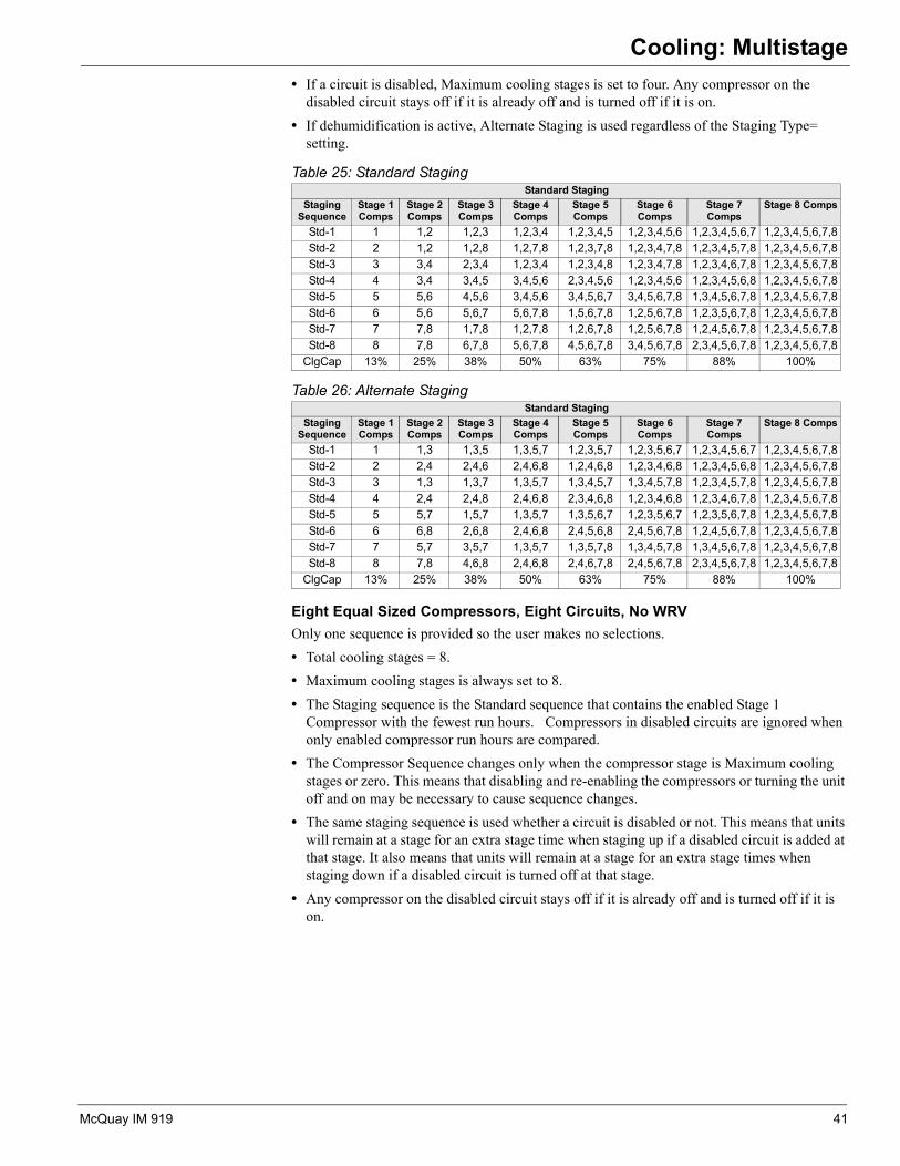
Eight Equal Sized Compressors, Eight Circuits, No WRVOnly one sequence is provided so the user makes no selections.• Total cooling stages = 8.• Maximum cooling stages is always set to 8. • The Staging sequence is the Standard sequence that contains the enabled Stage 1
Compressor with the fewest run hours. Compressors in disabled circuits are ignored when only enabled compressor run hours are compared.
• The Compressor Sequence changes only when the compressor stage is Maximum cooling stages or zero. This means that disabling and re-enabling the compressors or turning the unit off and on may be necessary to cause sequence changes.
• The same staging sequence is used whether a circuit is disabled or not. This means that units will remain at a stage for an extra stage time when staging up if a disabled circuit is added at that stage. It also means that units will remain at a stage for an extra stage times when staging down if a disabled circuit is turned off at that stage.
• Any compressor on the disabled circuit stays off if it is already off and is turned off if it is on.
Table 25: Standard StagingStandard Staging
Staging Sequence
Stage 1 Comps
Stage 2 Comps
Stage 3 Comps
Stage 4 Comps
Stage 5 Comps
Stage 6 Comps
Stage 7 Comps
Stage 8 Comps
Std-1 1 1,2 1,2,3 1,2,3,4 1,2,3,4,5 1,2,3,4,5,6 1,2,3,4,5,6,7 1,2,3,4,5,6,7,8Std-2 2 1,2 1,2,8 1,2,7,8 1,2,3,7,8 1,2,3,4,7,8 1,2,3,4,5,7,8 1,2,3,4,5,6,7,8Std-3 3 3,4 2,3,4 1,2,3,4 1,2,3,4,8 1,2,3,4,7,8 1,2,3,4,6,7,8 1,2,3,4,5,6,7,8Std-4 4 3,4 3,4,5 3,4,5,6 2,3,4,5,6 1,2,3,4,5,6 1,2,3,4,5,6,8 1,2,3,4,5,6,7,8Std-5 5 5,6 4,5,6 3,4,5,6 3,4,5,6,7 3,4,5,6,7,8 1,3,4,5,6,7,8 1,2,3,4,5,6,7,8Std-6 6 5,6 5,6,7 5,6,7,8 1,5,6,7,8 1,2,5,6,7,8 1,2,3,5,6,7,8 1,2,3,4,5,6,7,8Std-7 7 7,8 1,7,8 1,2,7,8 1,2,6,7,8 1,2,5,6,7,8 1,2,4,5,6,7,8 1,2,3,4,5,6,7,8Std-8 8 7,8 6,7,8 5,6,7,8 4,5,6,7,8 3,4,5,6,7,8 2,3,4,5,6,7,8 1,2,3,4,5,6,7,8
ClgCap 13% 25% 38% 50% 63% 75% 88% 100%
Table 26: Alternate StagingStandard Staging
Staging Sequence
Stage 1 Comps
Stage 2 Comps
Stage 3 Comps
Stage 4 Comps
Stage 5 Comps
Stage 6 Comps
Stage 7 Comps
Stage 8 Comps
Std-1 1 1,3 1,3,5 1,3,5,7 1,2,3,5,7 1,2,3,5,6,7 1,2,3,4,5,6,7 1,2,3,4,5,6,7,8Std-2 2 2,4 2,4,6 2,4,6,8 1,2,4,6,8 1,2,3,4,6,8 1,2,3,4,5,6,8 1,2,3,4,5,6,7,8Std-3 3 1,3 1,3,7 1,3,5,7 1,3,4,5,7 1,3,4,5,7,8 1,2,3,4,5,7,8 1,2,3,4,5,6,7,8Std-4 4 2,4 2,4,8 2,4,6,8 2,3,4,6,8 1,2,3,4,6,8 1,2,3,4,6,7,8 1,2,3,4,5,6,7,8Std-5 5 5,7 1,5,7 1,3,5,7 1,3,5,6,7 1,2,3,5,6,7 1,2,3,5,6,7,8 1,2,3,4,5,6,7,8Std-6 6 6,8 2,6,8 2,4,6,8 2,4,5,6,8 2,4,5,6,7,8 1,2,4,5,6,7,8 1,2,3,4,5,6,7,8Std-7 7 5,7 3,5,7 1,3,5,7 1,3,5,7,8 1,3,4,5,7,8 1,3,4,5,6,7,8 1,2,3,4,5,6,7,8Std-8 8 7,8 4,6,8 2,4,6,8 2,4,6,7,8 2,4,5,6,7,8 2,3,4,5,6,7,8 1,2,3,4,5,6,7,8
ClgCap 13% 25% 38% 50% 63% 75% 88% 100%
McQuay IM 919 41

Cooling: Multistage
Eight Equal Sized Compressors, Eight Circuits, WRVOnly one sequence is provided so the user makes no selections.• Total cooling stages = 8.• Maximum cooling stages is always set to 8. • If both circuit # 1 and circuit # 2 are enabled, the staging sequence is Std-1 if compressor # 1
has fewer hours than compressor # 2, and the staging sequence is Std-2 if compressor # 1 does not have fewer hours than compressor # 2.
• If Circuit # 1 is disabled, the staging sequence is Std-2. • If Circuit # 2 is disabled, the staging sequence is Std-1. • If both circuit # 1 and circuit # 2 are disabled, the staging sequence is Std-1. Only
compressors 3 through 8 are used.• The Compressor Sequence changes based on Run Time only when the compressor stage
equals Maximum cooling stages or zero. This means that disabling and re-enabling the compressors or turning the unit off and on may be necessary to cause sequence changes.
• The compressor sequence changes immediately if a circuit is disabled to keep either compressor # 1 or # 2 on. This will result is compressors being turned off and others being turned on in this emergency condition.
• The same staging sequence is used whether a circuit is disabled or not. This means that units will remain at a stage for an extra stage time when staging up if a disabled circuit is added at that stage. It also means that units will remain at a stage for an extra stage times when staging down if a disabled circuit is turned off at that stage.
• Any compressor on a disabled circuit stays off if it is already off and is turned off if it is on.
Table 27: Standard StagingStandard Staging
Staging Sequence
Stage 1 Comps
Stage 2 Comps
Stage 3 Comps
Stage 4 Comps
Stage 5 Comps
Stage 6 Comps
Stage 7 Comps
Stage 8 Comps
Std-1 1 1,2 1,2,3 1,2,3,4 1,2,3,4,5 1,2,3,4,5,6 1,2,3,4,5,6,7 1,2,3,4,5,6,7,8Std-2 2 1,2 1,2,8 1,2,7,8 1,2,3,7,8 1,2,3,4,7,8 1,2,3,4,5,7,8 1,2,3,4,5,6,7,8Std-3 3 3,4 2,3,4 1,2,3,4 1,2,3,4,8 1,2,3,4,7,8 1,2,3,4,6,7,8 1,2,3,4,5,6,7,8Std-4 4 3,4 3,4,5 3,4,5,6 2,3,4,5,6 1,2,3,4,5,6 1,2,3,4,5,6,8 1,2,3,4,5,6,7,8Std-5 5 5,6 4,5,6 3,4,5,6 3,4,5,6,7 3,4,5,6,7,8 1,3,4,5,6,7,8 1,2,3,4,5,6,7,8Std-6 6 5,6 5,6,7 5,6,7,8 1,5,6,7,8 1,2,5,6,7,8 1,2,3,5,6,7,8 1,2,3,4,5,6,7,8Std-7 7 7,8 1,7,8 1,2,7,8 1,2,6,7,8 1,2,5,6,7,8 1,2,4,5,6,7,8 1,2,3,4,5,6,7,8Std-8 8 7,8 6,7,8 5,6,7,8 4,5,6,7,8 3,4,5,6,7,8 2,3,4,5,6,7,8 1,2,3,4,5,6,7,8
ClgCap 13% 25% 38% 50% 63% 75% 88% 100%
Table 28: Standard StagingStandard Staging
Staging Sequence
Stage 1 Comps
Stage 2 Comps
Stage 3 Comps
Stage 4 Comps
Stage 5 Comps
Stage 6 Comps
Stage 7 Comps
Stage 8 Comps
Std-1 1 1,4 1,4,5 1,4,5,7 1,4,5,7,8 1,4,5,6,7,8 1,2,3,4,5,6,8 1,2,3,4,5,6,7,8Std-2 2 2,3 2,3,6 2,3,6,8 2,3,6,7,8 2,3,5,6,7,8 2,3,4,5,6,7,8 1,2,3,4,5,6,7,8
ClgCap 13% 25% 38% 50% 63% 75% 88% 100%
42 McQuay IM 919
Communication Module
Communication ModuleNetwork CommunicationsSee the Installation & Maintenance Manuals below for detailed instructionsIM 916 MicroTech III Rooftop Unit Controller - BACnet IP Communications
IM 917 MicroTech III Rooftop Unit Controller - BACnet MSTP Communications
IM 918 MicroTech III Rooftop Unit Controller - BACnet LON Communications
McQuay IM 919 43

Software Identification and Configuration
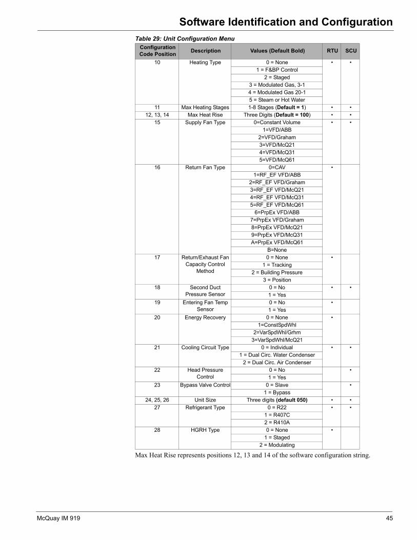
Software Identification and Configuration After the main control board application software is loaded into the MCB, it must be “configured” for the specific control application. This consists of setting the value of 23 configuration variables within the MCB. These variables define things such as the type of cooling, number of compressors and cooling stages and the type of heat. If all of these items are not set appropriately for the specific unit, the unit will not function properly. The correct settings for these parameters are defined for a given unit by the unit “Software Configuration Code”. The code consists of a 26-character string of numbers and letters. The code can be found on the Unit Software Identification Label located on the back side of the control panel door. Only the first 23 characters of this code are used for software configuration purposes. The table shown below lists the configuration code variables including the position within the code, description of the parameter, and the applicable settings for each. The default values are shown in bold font. The unit is configured at the factory however may also be configured in the field by accessing the Unit Configuration Menu. Once changes have been made to the Unit Configuration Menu, the Apply Changes flag must be changed from no to yes in order for the controller to recognize the changes. Setting the Apply Changes flag to YES will automatically cycle power to the controller.Table 29: Unit Configuration MenuConfiguration Code Position Description Values (Default Bold) RTU SCU
1 Unit Type 0 = Rooftop (RTU) • •1 = Self-Contained (SCU)
2 Control Type 0 = Zone Control • •1 = DAT Control
3 Cooling Type 0 = None • •1 = Compressorized Clg
2 = Chilled Water3 = F&BP
4 Compressorized Cooling
Configuration
0 = None • •1 = Generic Condenser2 = 2Cmp/2Circ/3Stg3 = 3Cmp/2Circ/4Stg4 = 2Cmp/2Circ/2Stg
5 = 3Cmp/3Circ/3Stg_NoWRV6 = 3Cmp/3Circ/3Stg_WRV
7 = 4Cmp/2Circ/4Stg8 = 4Cmp/4Circ/4Stg_NoWRV
9 = 4Cmp/4Circ/4Stg_WRVA = 6Cmp/2Circ/6Stg
B = 6Cmp/6Circ/6Stg_NoWRVC = 6Cmp/6Circ/6Stg_WRV
5 Generic Condenser Stages
1 – 8 Stages (default = 8) •
6 Low Ambient 0 = No •1 = Yes
7 Evaporative Condenser Control
0 = No Evap •1 = Evap _ No VFD
2 = Evap ABB3 = Evap McQ21
8 Damper Type 0 = None • •1 = Single Position 30%2 = Single Position 100%3 = Economizer Airside
4 = Economizer Waterside9 Design Flow 0 = No Design Flow •
1 = 018-030 (800)2 = 036-040 (802)3 = 045-075 (047)4 = 080-135 (077)
44 McQuay IM 919
Software Identification and Configuration
Max Heat Rise represents positions 12, 13 and 14 of the software configuration string.
10 Heating Type 0 = None • •1 = F&BP Control
2 = Staged3 = Modulated Gas, 3-14 = Modulated Gas 20-15 = Steam or Hot Water
11 Max Heating Stages 1-8 Stages (Default = 1) • •12, 13, 14 Max Heat Rise Three Digits (Default = 100) • •
15 Supply Fan Type 0=Constant Volume • •1=VFD/ABB
2=VFD/Graham3=VFD/McQ214=VFD/McQ315=VFD/McQ61
16 Return Fan Type 0=CAV •1=RF_EF VFD/ABB
2=RF_EF VFD/Graham3=RF_EF VFD/McQ214=RF_EF VFD/McQ315=RF_EF VFD/McQ61
6=PrpEx VFD/ABB7=PrpEx VFD/Graham8=PrpEx VFD/McQ219=PrpEx VFD/McQ31A=PrpEx VFD/McQ61
B=None17 Return/Exhaust Fan
Capacity Control Method
0 = None •1 = Tracking
2 = Building Pressure3 = Position
18 Second Duct Pressure Sensor
0 = No • •1 = Yes
19 Entering Fan Temp Sensor
0 = No •1 = Yes
20 Energy Recovery 0 = None •1=ConstSpdWhl
2=VarSpdWhl/Grhm3=VarSpdWhl/McQ21
21 Cooling Circuit Type 0 = Individual • •1 = Dual Circ. Water Condenser
2 = Dual Circ. Air Condenser22 Head Pressure
Control0 = No •1 = Yes
23 Bypass Valve Control 0 = Slave •1 = Bypass
24, 25, 26 Unit Size Three digits (default 050) • •27 Refrigerant Type 0 = R22 • •
1 = R407C2 = R410A
28 HGRH Type 0 = None •1 = Staged
2 = Modulating
Table 29: Unit Configuration MenuConfiguration Code Position Description Values (Default Bold) RTU SCU
McQuay IM 919 45
Typical Electrical Drawings - Rooftop
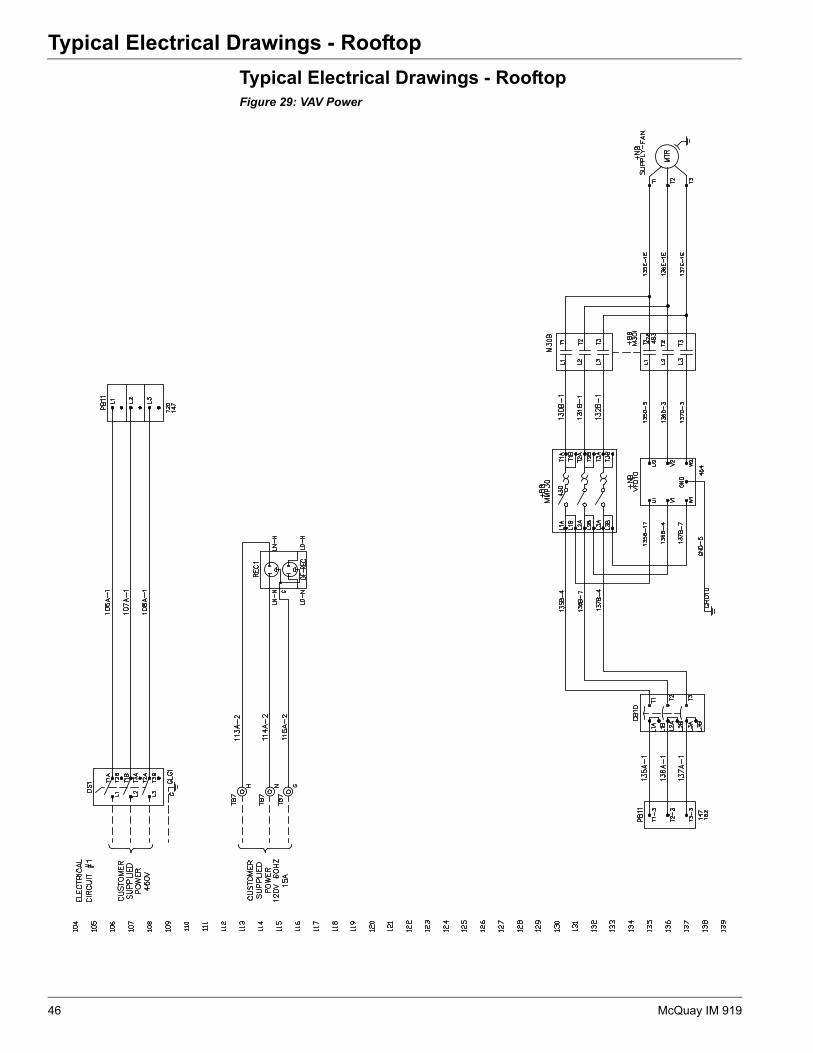
Typical Electrical Drawings - RooftopFigure 29: VAV Power46 McQuay IM 919

Typical Electrical Drawings - Rooftop
Figure 30: VAV Power (Continued)McQuay IM 919 47

Typical Electrical Drawings - Rooftop
Figure 31: Controller Inputs48 McQuay IM 919

Typical Electrical Drawings - Rooftop
Figure 32: Controller Inputs (Continued)McQuay IM 919 49
Typical Electrical Drawings - Rooftop
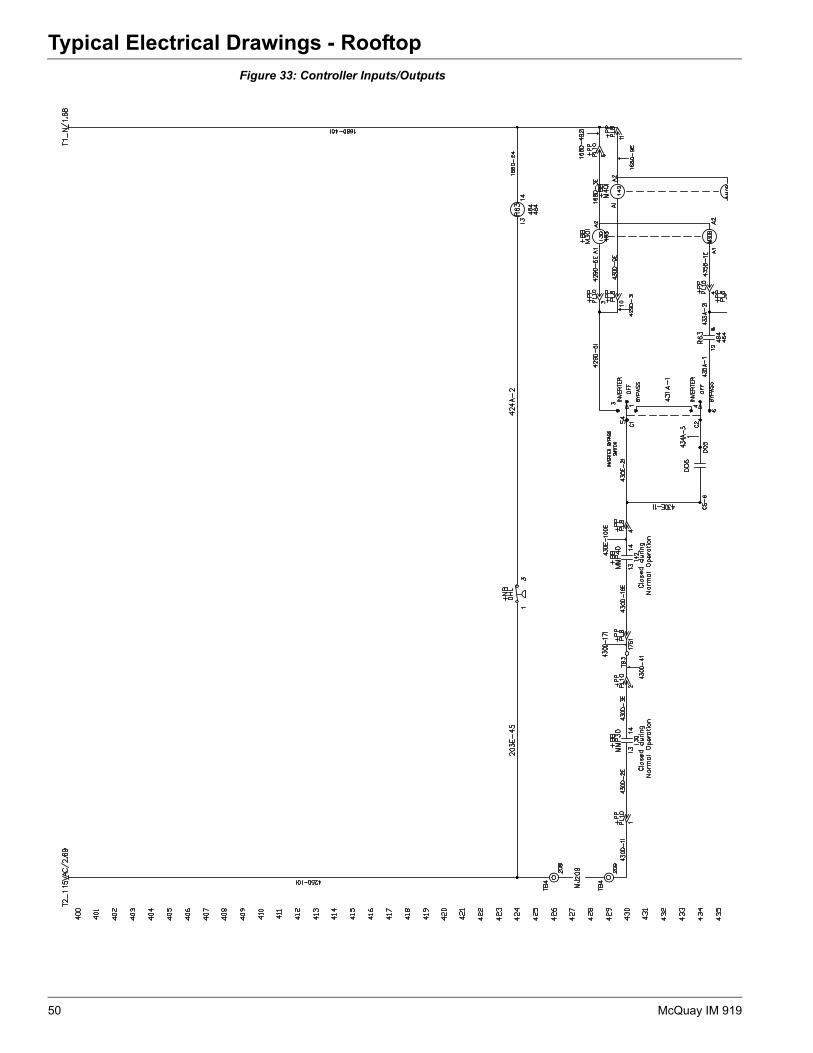
Figure 33: Controller Inputs/Outputs50 McQuay IM 919

Typical Electrical Drawings - Rooftop
Figure 34: Controller Inputs/Outputs (Continued)McQuay IM 919 51

Typical Electrical Drawings - Rooftop
Figure 35: VFD Power52 McQuay IM 919

Typical Electrical Drawings - Rooftop
Figure 36: Condenser Section PowerMcQuay IM 919 53
Typical Electrical Drawings - Rooftop
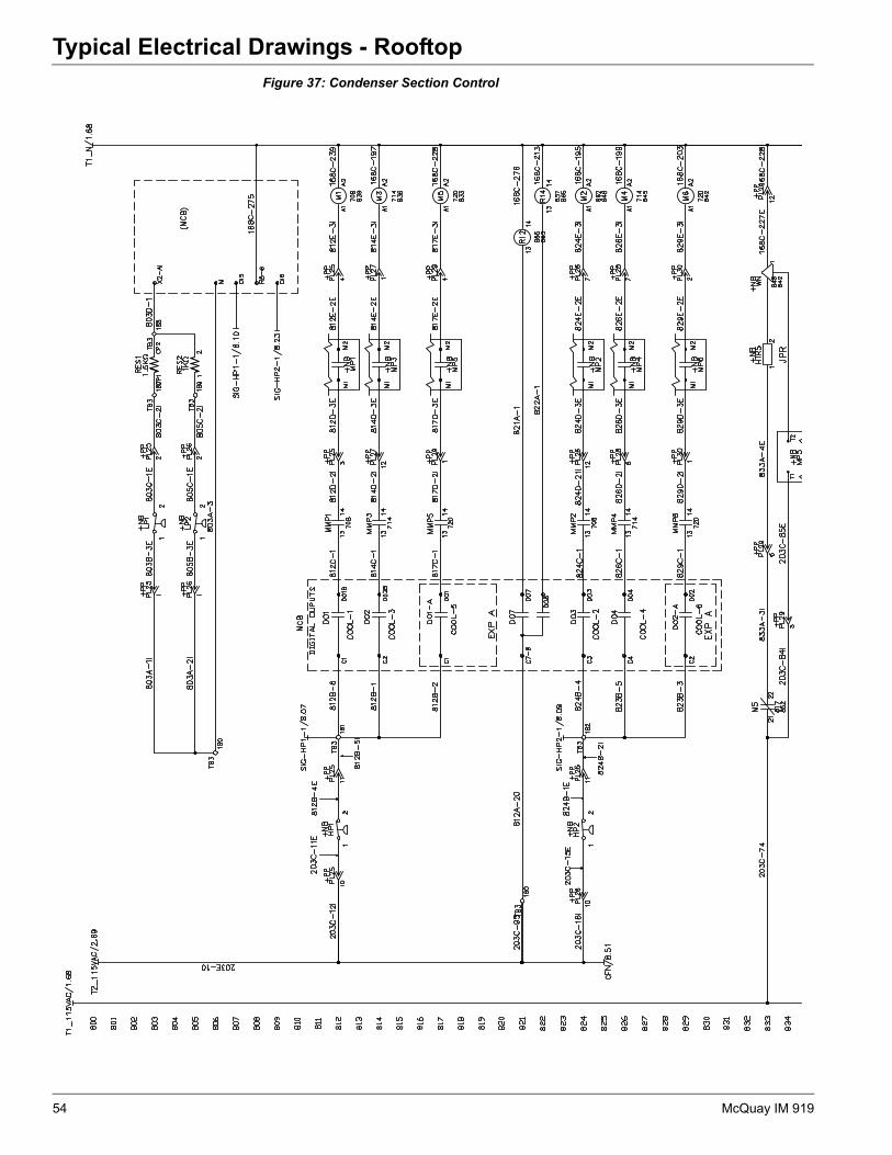
Figure 37: Condenser Section Control54 McQuay IM 919

Typical Electrical Drawings - Rooftop
Figure 38: Condenser Section Control (Continued)McQuay IM 919 55
Typical Electrical Drawings - Self Contained
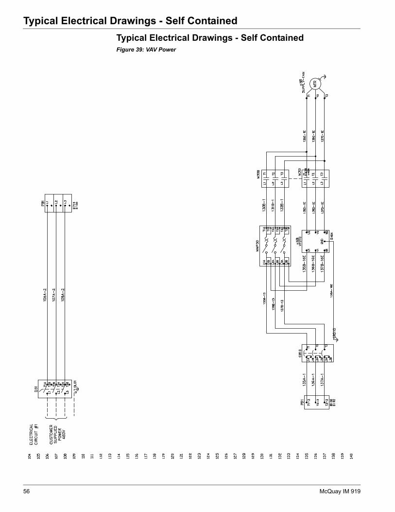
Typical Electrical Drawings - Self ContainedFigure 39: VAV Power56 McQuay IM 919

Typical Electrical Drawings - Self Contained
Figure 40: VAV Power (Continued)McQuay IM 919 57
Typical Electrical Drawings - Self Contained
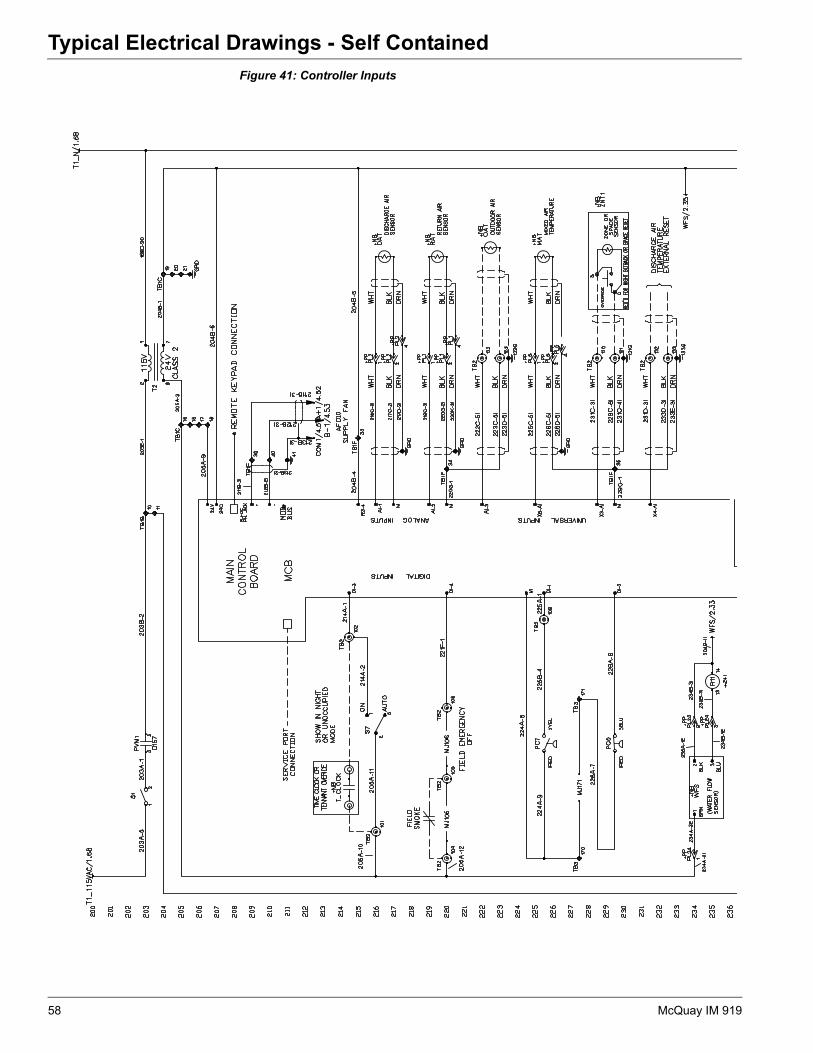
Figure 41: Controller Inputs58 McQuay IM 919

Typical Electrical Drawings - Self Contained
Figure 42: Controller Inputs/OutputsMcQuay IM 919 59

Typical Electrical Drawings - Self Contained
Figure 43: VFD Control60 McQuay IM 919

Typical Electrical Drawings - Self Contained
Figure 44: VFD Control (Continued)McQuay IM 919 61
Typical Electrical Drawings - Self Contained
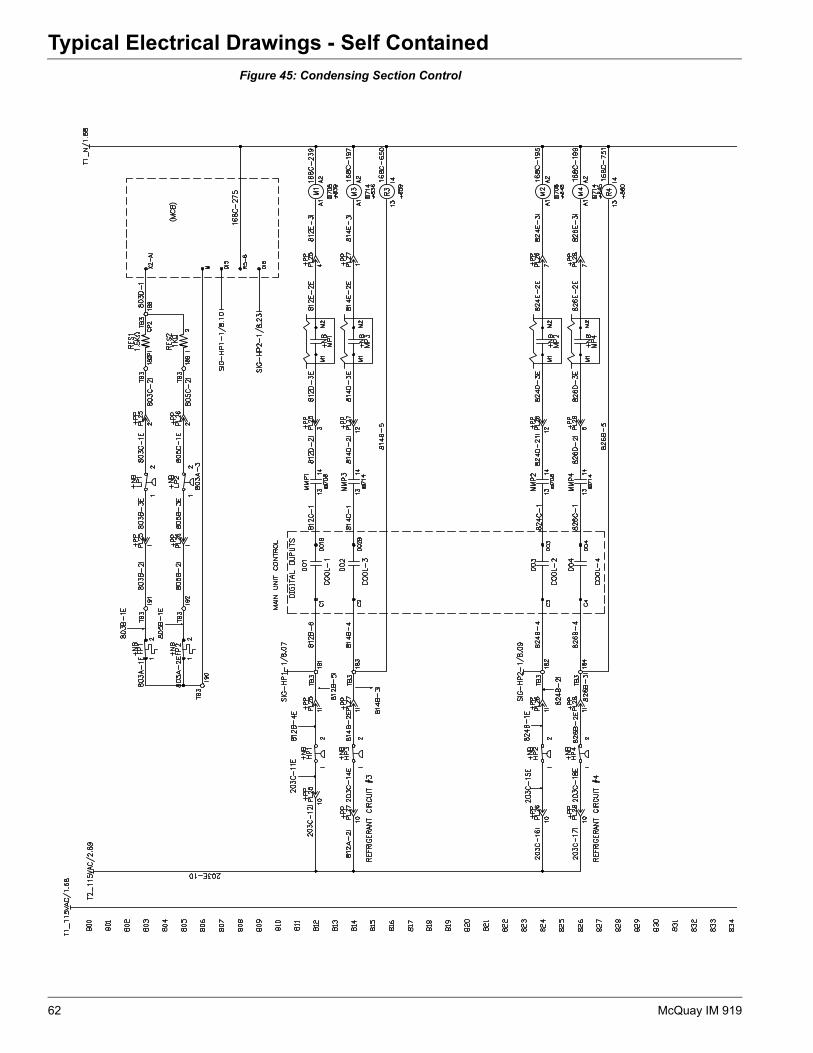
Figure 45: Condensing Section Control62 McQuay IM 919

Typical Electrical Drawings - Self Contained
Figure 46: Condensing Section Control (Continued)McQuay IM 919 63

Parts List
Parts ListComponent Designation Description McQuay Part
Number
MCB Main Control Board - MTIII 193407301
EXP A, B, C Expansion Module 193407501
ZNT1 Zone Temperature Sensor with Tenant Override 113117701
ZNT1 Zone Temperature Sensor with Tenant Override & Remote set point adjustment
113117801
DAT Discharge Air Temperature Sensor 193414600
EFT Entering Fan Air Temperature Sensor 193414600
OAT Outside Air Temperature Sensor 193414600
RAT Return Air Temperature Sensor 193414600
MAT Mixed Air Temperature Sensor 193414600
EWT Entering Water Temperature Sensor 193414600
ER DAT Energy Recovery Wheel Discharge Air Temperature Sensor 193414600
ER Exh T Energy Recovery Wheel Exhaust Air Temperature Sensor 193414600
SPS1, 2 Duct Static Pressure Sensor 049545013
SPS3 Building Static Pressure Sensor 049545012
PSR1 Refrigerant Pressure Transducer Circuit 1 065816802
PSR2 Refrigerant Pressure Transducer Circuit 2 065816802
T2 Transformer 115/24 VAC 349937303
T3 Transformer 115/24 VAC 349937303
T9 Transformer 115/24 VAC N/A
SHS1 Space Humidity Sensor, Wall Mount 067294901
SHS1 Space Humidity Sensor, Duct Mount 067295001
WFS Water Flow Switch 098867101
PC5 Dirty filter switch: prefilter 065493801
PC6 Dirty filter switch: final filter 065493801
PC7 Airflow proving switch 060015801
DHL Duct High Limit 065493801
OAE Enthalpy Control, Electro-Mechanical 030706702
OAE Enthalpy Control, Comparative 049262201
RAE Return Air Enthalpy Sensor 049262202
SD1 Smoke Detector: Supply Air 098873101
SD2 Smoke Detector: Return Air 098873101
- Communication Module - LON 193408201
- Communication Module - BACnet MSTP 193408301
- Communication Module - BACnet IP 193408401
- Controller Terminal Block - 2 pole 193410402
- Controller Terminal Block - 3 pole 193410403
Controller Terminal Block - 5 pole 193410405
Controller Terminal Block - 6 pole 193410406
Controller Terminal Block - 7 pole 193410407
Controller Terminal Block - 8 pole 193410408
64 McQuay IM 919


© 2008 McQuay International • www.mcquay.com • 800-432-1342
McQuay Training and Development
Now that you have made an investment in modern, efficient McQuay equipment, its care should be a high priority. For training information on all McQuay HVAC products, please visit us at www.mcquay.com and click on training, or call 540-248-9646 and ask for the Training Department.
WarrantyAll McQuay equipment is sold pursuant to its standard terms and conditions of sale, including Limited Product Warranty. Consult your local McQuay Representative for warranty details. Refer to Form 933-43285Y. To find your local McQuay Representative, go to www.mcquay.com.
This document contains the most current product information as of this printing. For the most up-to-date product information, please go to www.mcquay.com.