![]project-open[ Workflow Developer Tutorial Part 3](https://static.fdocuments.in/doc/165x107/54b38de14a795968368b46d7/project-open-workflow-developer-tutorial-part-3.jpg)
Part Developer Tutorial - clermont-universite · Allegro Design Entry HDL ... see Part Developer...
155
Part Developer Tutorial Product Version 16.01 December 2007
Transcript of Part Developer Tutorial - clermont-universite · Allegro Design Entry HDL ... see Part Developer...

Part Developer Tutorial
Product Version 16.01December 2007

1998-2007 Cadence Design Systems, Inc. All rights reserved.Portions © Apache Software Foundation, Sun Microsystems, Free Software Foundation, Inc., Regents ofthe University of California, Massachusetts Institute of Technology, University of Florida. Used bypermission. Printed in the United States of America.
Cadence Design Systems, Inc., 555 River Oaks Parkway, San Jose, CA 95134, USA
Allegro Part Developer contains technology licensed from, and copyrighted by: Apache SoftwareFoundation, 1901 Munsey Drive Forest Hill, MD 21050, USA © 2000-2005, Apache Software Foundation.Sun Microsystems, 4150 Network Circle, Santa Clara, CA 95054 USA © 1994-2007, Sun Microsystems,Inc. Free Software Foundation, 59 Temple Place, Suite 330, Boston, MA 02111-1307 USA © 1989, 1991,Free Software Foundation, Inc. Regents of the University of California, Sun Microsystems, Inc., ScripticsCorporation, © 2001, Regents of the University of California. Daniel Stenberg, © 1996 - 2006, DanielStenberg. UMFPACK © 2005, Timothy A. Davis, University of Florida, ([email protected]). Ken Martin, WillSchroeder, Bill Lorensen © 1993-2002, Ken Martin, Will Schroeder, Bill Lorensen. Massachusetts Instituteof Technology, 77 Massachusetts Avenue, Cambridge, Massachusetts, USA © 2003, the Board of Trusteesof Massachusetts Institute of Technology. All rights reserved.
Trademarks: Trademarks and service marks of Cadence Design Systems, Inc. (Cadence) contained inthis document are attributed to Cadence with the appropriate symbol. For queries regarding Cadence’strademarks, contact the corporate legal department at the address shown above or call 800.862.4522.
Open SystemC, Open SystemC Initiative, OSCI, SystemC, and SystemC Initiative are trademarks orregistered trademarks of Open SystemC Initiative, Inc. in the United States and other countries and areused with permission.
All other trademarks are the property of their respective holders.
Restricted Print Permission: This publication is protected by copyright and any unauthorized use of thispublication may violate copyright, trademark, and other laws. Except as specified in this permissionstatement, this publication may not be copied, reproduced, modified, published, uploaded, posted,transmitted, or distributed in any way, without prior written permission from Cadence. This statement grantsyou permission to print one (1) hard copy of this publication subject to the following conditions:
1. The publication may be used solely for personal, informational, and noncommercial purposes;2. The publication may not be modified in any way;3. Any copy of the publication or portion thereof must include all original copyright, trademark, and other
proprietary notices and this permission statement; and4. Cadence reserves the right to revoke this authorization at any time, and any such use shall be
discontinued immediately upon written notice from Cadence.
Patents: Allegro Part Developer, described in this document, is protected by U.S. Patents 5,481,695;5,510,998; 5,550,748; 5,590,049; 5,625,565; 5,715,408; 6,516,447; 6,594,799; 6,851,094; 7,017,137;7,143,341; 7,168,041.
Disclaimer: Information in this publication is subject to change without notice and does not represent acommitment on the part of Cadence. The information contained herein is the proprietary and confidentialinformation of Cadence or its licensors, and is supplied subject to, and may be used only by Cadence’scustomer in accordance with, a written agreement between Cadence and its customer. Except as may beexplicitly set forth in such agreement, Cadence does not make, and expressly disclaims, anyrepresentations or warranties as to the completeness, accuracy or usefulness of the information containedin this document. Cadence does not warrant that use of such information will not infringe any third partyrights, nor does Cadence assume any liability for damages or costs of any kind that may result from use ofsuch information.
Restricted Rights: Use, duplication, or disclosure by the Government is subject to restrictions as set forthin FAR52.227-14 and DFAR252.227-7013 et seq. or its successor.

Part Developer Tutorial
Contents
1Introduction . . . . . . . . . . . . . . . . . . . . . . . . . . . . . . . . . . . . . . . . . . . . . . . . . . . . . . . . 11
Audience Profile . . . . . . . . . . . . . . . . . . . . . . . . . . . . . . . . . . . . . . . . . . . . . . . . . . . . . . . . 12Pre-Requisites . . . . . . . . . . . . . . . . . . . . . . . . . . . . . . . . . . . . . . . . . . . . . . . . . . . . . . . . . 12How to Use This Tutorial . . . . . . . . . . . . . . . . . . . . . . . . . . . . . . . . . . . . . . . . . . . . . . . . . 12Using the Samples . . . . . . . . . . . . . . . . . . . . . . . . . . . . . . . . . . . . . . . . . . . . . . . . . . . . . . 12Chapter Overviews . . . . . . . . . . . . . . . . . . . . . . . . . . . . . . . . . . . . . . . . . . . . . . . . . . . . . 13
2Getting Started . . . . . . . . . . . . . . . . . . . . . . . . . . . . . . . . . . . . . . . . . . . . . . . . . . . . 15
Objective . . . . . . . . . . . . . . . . . . . . . . . . . . . . . . . . . . . . . . . . . . . . . . . . . . . . . . . . . . . . . 15Part Definition . . . . . . . . . . . . . . . . . . . . . . . . . . . . . . . . . . . . . . . . . . . . . . . . . . . . . . . . . 15Part Types . . . . . . . . . . . . . . . . . . . . . . . . . . . . . . . . . . . . . . . . . . . . . . . . . . . . . . . . . . . . 16
Symmetrical Parts . . . . . . . . . . . . . . . . . . . . . . . . . . . . . . . . . . . . . . . . . . . . . . . . . . . 16Asymmetrical Parts . . . . . . . . . . . . . . . . . . . . . . . . . . . . . . . . . . . . . . . . . . . . . . . . . . 16Split Parts . . . . . . . . . . . . . . . . . . . . . . . . . . . . . . . . . . . . . . . . . . . . . . . . . . . . . . . . . . 17
Part Creation Methodology . . . . . . . . . . . . . . . . . . . . . . . . . . . . . . . . . . . . . . . . . . . . . . . 17Starting the Tool . . . . . . . . . . . . . . . . . . . . . . . . . . . . . . . . . . . . . . . . . . . . . . . . . . . . . . . . 19Summary . . . . . . . . . . . . . . . . . . . . . . . . . . . . . . . . . . . . . . . . . . . . . . . . . . . . . . . . . . . . . 20
3Creating a Flat Part. . . . . . . . . . . . . . . . . . . . . . . . . . . . . . . . . . . . . . . . . . . . . . . 21
Objective . . . . . . . . . . . . . . . . . . . . . . . . . . . . . . . . . . . . . . . . . . . . . . . . . . . . . . . . . . . . . 21Overview . . . . . . . . . . . . . . . . . . . . . . . . . . . . . . . . . . . . . . . . . . . . . . . . . . . . . . . . . . . . . 21Setting Up Part Developer . . . . . . . . . . . . . . . . . . . . . . . . . . . . . . . . . . . . . . . . . . . . . . . . 22
Task Overview . . . . . . . . . . . . . . . . . . . . . . . . . . . . . . . . . . . . . . . . . . . . . . . . . . . . . . 23Steps . . . . . . . . . . . . . . . . . . . . . . . . . . . . . . . . . . . . . . . . . . . . . . . . . . . . . . . . . . . . . 23
Creating the n87c196nt Part . . . . . . . . . . . . . . . . . . . . . . . . . . . . . . . . . . . . . . . . . . . . . . 28Task Overview . . . . . . . . . . . . . . . . . . . . . . . . . . . . . . . . . . . . . . . . . . . . . . . . . . . . . . 28Steps . . . . . . . . . . . . . . . . . . . . . . . . . . . . . . . . . . . . . . . . . . . . . . . . . . . . . . . . . . . . . 28
December 2007 3 Product Version 16.01

Part Developer Tutorial
Creating a Package . . . . . . . . . . . . . . . . . . . . . . . . . . . . . . . . . . . . . . . . . . . . . . . . . . . . . 29Task Overview . . . . . . . . . . . . . . . . . . . . . . . . . . . . . . . . . . . . . . . . . . . . . . . . . . . . . . 29Steps . . . . . . . . . . . . . . . . . . . . . . . . . . . . . . . . . . . . . . . . . . . . . . . . . . . . . . . . . . . . . 29
Entering the Logical Pins . . . . . . . . . . . . . . . . . . . . . . . . . . . . . . . . . . . . . . . . . . . . . . . . . 31Task Overview . . . . . . . . . . . . . . . . . . . . . . . . . . . . . . . . . . . . . . . . . . . . . . . . . . . . . . 31Steps . . . . . . . . . . . . . . . . . . . . . . . . . . . . . . . . . . . . . . . . . . . . . . . . . . . . . . . . . . . . . 31
Specifying the Footprints . . . . . . . . . . . . . . . . . . . . . . . . . . . . . . . . . . . . . . . . . . . . . . . . . 34Task Overview . . . . . . . . . . . . . . . . . . . . . . . . . . . . . . . . . . . . . . . . . . . . . . . . . . . . . . 34Steps . . . . . . . . . . . . . . . . . . . . . . . . . . . . . . . . . . . . . . . . . . . . . . . . . . . . . . . . . . . . . 34Setting a Filter . . . . . . . . . . . . . . . . . . . . . . . . . . . . . . . . . . . . . . . . . . . . . . . . . . . . . . 35
Entering Physical Pins . . . . . . . . . . . . . . . . . . . . . . . . . . . . . . . . . . . . . . . . . . . . . . . . . . . 37Task Overview . . . . . . . . . . . . . . . . . . . . . . . . . . . . . . . . . . . . . . . . . . . . . . . . . . . . . . 37Steps . . . . . . . . . . . . . . . . . . . . . . . . . . . . . . . . . . . . . . . . . . . . . . . . . . . . . . . . . . . . . 37
Moving Pins from Logical Pins to Global Pins . . . . . . . . . . . . . . . . . . . . . . . . . . . . . . . . . 38Task Overview . . . . . . . . . . . . . . . . . . . . . . . . . . . . . . . . . . . . . . . . . . . . . . . . . . . . . . 38Steps . . . . . . . . . . . . . . . . . . . . . . . . . . . . . . . . . . . . . . . . . . . . . . . . . . . . . . . . . . . . . 39
Pin Mapping . . . . . . . . . . . . . . . . . . . . . . . . . . . . . . . . . . . . . . . . . . . . . . . . . . . . . . . . . . . 39Task Overview . . . . . . . . . . . . . . . . . . . . . . . . . . . . . . . . . . . . . . . . . . . . . . . . . . . . . . 39Steps . . . . . . . . . . . . . . . . . . . . . . . . . . . . . . . . . . . . . . . . . . . . . . . . . . . . . . . . . . . . . 39
Hiding Mapped Pins . . . . . . . . . . . . . . . . . . . . . . . . . . . . . . . . . . . . . . . . . . . . . . . . . . . . . 40Task Overview . . . . . . . . . . . . . . . . . . . . . . . . . . . . . . . . . . . . . . . . . . . . . . . . . . . . . . 40Steps . . . . . . . . . . . . . . . . . . . . . . . . . . . . . . . . . . . . . . . . . . . . . . . . . . . . . . . . . . . . . 40Continuing Pin Mapping . . . . . . . . . . . . . . . . . . . . . . . . . . . . . . . . . . . . . . . . . . . . . . . 41
Creating Symbols . . . . . . . . . . . . . . . . . . . . . . . . . . . . . . . . . . . . . . . . . . . . . . . . . . . . . . 41Task Overview . . . . . . . . . . . . . . . . . . . . . . . . . . . . . . . . . . . . . . . . . . . . . . . . . . . . . . 41Steps . . . . . . . . . . . . . . . . . . . . . . . . . . . . . . . . . . . . . . . . . . . . . . . . . . . . . . . . . . . . . 41
Summary . . . . . . . . . . . . . . . . . . . . . . . . . . . . . . . . . . . . . . . . . . . . . . . . . . . . . . . . . . . . . 43
4Creating Parts from CSV Files . . . . . . . . . . . . . . . . . . . . . . . . . . . . . . . . . . 44
Objective . . . . . . . . . . . . . . . . . . . . . . . . . . . . . . . . . . . . . . . . . . . . . . . . . . . . . . . . . . . . . 44Overview . . . . . . . . . . . . . . . . . . . . . . . . . . . . . . . . . . . . . . . . . . . . . . . . . . . . . . . . . . . . . 44The CSV File Format . . . . . . . . . . . . . . . . . . . . . . . . . . . . . . . . . . . . . . . . . . . . . . . . . . . . 45Importing Data from a CSV File . . . . . . . . . . . . . . . . . . . . . . . . . . . . . . . . . . . . . . . . . . . . 46
Task Overview . . . . . . . . . . . . . . . . . . . . . . . . . . . . . . . . . . . . . . . . . . . . . . . . . . . . . . 47
December 2007 4 Product Version 16.01
Part Developer Tutorial
Steps . . . . . . . . . . . . . . . . . . . . . . . . . . . . . . . . . . . . . . . . . . . . . . . . . . . . . . . . . . . . . 48Summary . . . . . . . . . . . . . . . . . . . . . . . . . . . . . . . . . . . . . . . . . . . . . . . . . . . . . . . . . . . . . 52
5Creating Split Parts . . . . . . . . . . . . . . . . . . . . . . . . . . . . . . . . . . . . . . . . . . . . . . . 53
Objective . . . . . . . . . . . . . . . . . . . . . . . . . . . . . . . . . . . . . . . . . . . . . . . . . . . . . . . . . . . . . 53Overview . . . . . . . . . . . . . . . . . . . . . . . . . . . . . . . . . . . . . . . . . . . . . . . . . . . . . . . . . . . . . 53Methodology for Creating Split Parts . . . . . . . . . . . . . . . . . . . . . . . . . . . . . . . . . . . . . . . . 53
Task Overview . . . . . . . . . . . . . . . . . . . . . . . . . . . . . . . . . . . . . . . . . . . . . . . . . . . . . . 54Steps . . . . . . . . . . . . . . . . . . . . . . . . . . . . . . . . . . . . . . . . . . . . . . . . . . . . . . . . . . . . . 54
Summary . . . . . . . . . . . . . . . . . . . . . . . . . . . . . . . . . . . . . . . . . . . . . . . . . . . . . . . . . . . . . 61
6Creating Parts from PDFs . . . . . . . . . . . . . . . . . . . . . . . . . . . . . . . . . . . . . . . 62
Objective . . . . . . . . . . . . . . . . . . . . . . . . . . . . . . . . . . . . . . . . . . . . . . . . . . . . . . . . . . . . . 62Overview . . . . . . . . . . . . . . . . . . . . . . . . . . . . . . . . . . . . . . . . . . . . . . . . . . . . . . . . . . . . . 62Creating Parts from PDFs . . . . . . . . . . . . . . . . . . . . . . . . . . . . . . . . . . . . . . . . . . . . . . . . 62
Task Overview . . . . . . . . . . . . . . . . . . . . . . . . . . . . . . . . . . . . . . . . . . . . . . . . . . . . . . 62Steps . . . . . . . . . . . . . . . . . . . . . . . . . . . . . . . . . . . . . . . . . . . . . . . . . . . . . . . . . . . . . 63
Summary . . . . . . . . . . . . . . . . . . . . . . . . . . . . . . . . . . . . . . . . . . . . . . . . . . . . . . . . . . . . . 67
7Creating Asymmetrical Parts . . . . . . . . . . . . . . . . . . . . . . . . . . . . . . . . . . . . 68
Objective . . . . . . . . . . . . . . . . . . . . . . . . . . . . . . . . . . . . . . . . . . . . . . . . . . . . . . . . . . . . . 68Overview . . . . . . . . . . . . . . . . . . . . . . . . . . . . . . . . . . . . . . . . . . . . . . . . . . . . . . . . . . . . . 68
Understanding the LS241 Part . . . . . . . . . . . . . . . . . . . . . . . . . . . . . . . . . . . . . . . . . . 68Task Overview . . . . . . . . . . . . . . . . . . . . . . . . . . . . . . . . . . . . . . . . . . . . . . . . . . . . . . 69Steps . . . . . . . . . . . . . . . . . . . . . . . . . . . . . . . . . . . . . . . . . . . . . . . . . . . . . . . . . . . . . 69
Summary . . . . . . . . . . . . . . . . . . . . . . . . . . . . . . . . . . . . . . . . . . . . . . . . . . . . . . . . . . . . . 73
8Working with Differential Pairs . . . . . . . . . . . . . . . . . . . . . . . . . . . . . . . . . . 74
Objective . . . . . . . . . . . . . . . . . . . . . . . . . . . . . . . . . . . . . . . . . . . . . . . . . . . . . . . . . . . . . 74
December 2007 5 Product Version 16.01

Part Developer Tutorial
Overview . . . . . . . . . . . . . . . . . . . . . . . . . . . . . . . . . . . . . . . . . . . . . . . . . . . . . . . . . . . . . 74Points to Remember about Differential Pair Support in Part Developer . . . . . . . . . . . 74
Autocreating Differential Pairs in All Cells of a Library . . . . . . . . . . . . . . . . . . . . . . . . . . . 75Configuring the Default Differential Pair Recognition Rule for a Project . . . . . . . . . . . 75Configuring the Low Assertion Setup to Disallow the Use of the _N Suffix . . . . . . . . 76Running the con2con Utility on a Library with the autocreatediffpair Option . . . . . . . 77
Autocreating Differential Pairs through the Package Editor . . . . . . . . . . . . . . . . . . . . . . . 78Creating a Differential Pair from Selected Pins . . . . . . . . . . . . . . . . . . . . . . . . . . . . . . . . 81Removing Differential Pair Properties from a Differential Pair . . . . . . . . . . . . . . . . . . . . . 83Summary . . . . . . . . . . . . . . . . . . . . . . . . . . . . . . . . . . . . . . . . . . . . . . . . . . . . . . . . . . . . . 83
9Creating Sizeable and HAS_FIXED_SIZE Symbols . . . . . . . . . 84
Objective . . . . . . . . . . . . . . . . . . . . . . . . . . . . . . . . . . . . . . . . . . . . . . . . . . . . . . . . . . . . . 84Overview . . . . . . . . . . . . . . . . . . . . . . . . . . . . . . . . . . . . . . . . . . . . . . . . . . . . . . . . . . . . . 84Methodology . . . . . . . . . . . . . . . . . . . . . . . . . . . . . . . . . . . . . . . . . . . . . . . . . . . . . . . . . . 85
Task Overview . . . . . . . . . . . . . . . . . . . . . . . . . . . . . . . . . . . . . . . . . . . . . . . . . . . . . . 85Steps . . . . . . . . . . . . . . . . . . . . . . . . . . . . . . . . . . . . . . . . . . . . . . . . . . . . . . . . . . . . . 85Creating a Sizeable Symbol . . . . . . . . . . . . . . . . . . . . . . . . . . . . . . . . . . . . . . . . . . . . 87
Summary . . . . . . . . . . . . . . . . . . . . . . . . . . . . . . . . . . . . . . . . . . . . . . . . . . . . . . . . . . . . . 91
10Modifying Packages . . . . . . . . . . . . . . . . . . . . . . . . . . . . . . . . . . . . . . . . . . . . . . 92
Objective . . . . . . . . . . . . . . . . . . . . . . . . . . . . . . . . . . . . . . . . . . . . . . . . . . . . . . . . . . . . . 92Overview . . . . . . . . . . . . . . . . . . . . . . . . . . . . . . . . . . . . . . . . . . . . . . . . . . . . . . . . . . . . . 92Adding Pins to a Package . . . . . . . . . . . . . . . . . . . . . . . . . . . . . . . . . . . . . . . . . . . . . . . . 93Adding Properties to a Package . . . . . . . . . . . . . . . . . . . . . . . . . . . . . . . . . . . . . . . . . . . 94Deleting Pins from a Package . . . . . . . . . . . . . . . . . . . . . . . . . . . . . . . . . . . . . . . . . . . . . 95Deleting Pins from All Packages and Symbols . . . . . . . . . . . . . . . . . . . . . . . . . . . . . . . . 96Modifying Pin Types . . . . . . . . . . . . . . . . . . . . . . . . . . . . . . . . . . . . . . . . . . . . . . . . . . . . . 97Moving Logical Pins to Global Pins . . . . . . . . . . . . . . . . . . . . . . . . . . . . . . . . . . . . . . . . . 98Moving Global Pins to Logical Pins . . . . . . . . . . . . . . . . . . . . . . . . . . . . . . . . . . . . . . . . . 99Adding Package Pin Properties . . . . . . . . . . . . . . . . . . . . . . . . . . . . . . . . . . . . . . . . . . . 100Specifying Pin Swappability . . . . . . . . . . . . . . . . . . . . . . . . . . . . . . . . . . . . . . . . . . . . . . 102Summary . . . . . . . . . . . . . . . . . . . . . . . . . . . . . . . . . . . . . . . . . . . . . . . . . . . . . . . . . . . . 103
December 2007 6 Product Version 16.01

Part Developer Tutorial
11Modifying Symbols . . . . . . . . . . . . . . . . . . . . . . . . . . . . . . . . . . . . . . . . . . . . . . 104
Objective . . . . . . . . . . . . . . . . . . . . . . . . . . . . . . . . . . . . . . . . . . . . . . . . . . . . . . . . . . . . 104Overview . . . . . . . . . . . . . . . . . . . . . . . . . . . . . . . . . . . . . . . . . . . . . . . . . . . . . . . . . . . . 104Adding Pins to a Symbol . . . . . . . . . . . . . . . . . . . . . . . . . . . . . . . . . . . . . . . . . . . . . . . . 105Adding Properties to a Symbol . . . . . . . . . . . . . . . . . . . . . . . . . . . . . . . . . . . . . . . . . . . 106Adding Symbol Pin Properties . . . . . . . . . . . . . . . . . . . . . . . . . . . . . . . . . . . . . . . . . . . . 107Modifying Symbol Pin Properties . . . . . . . . . . . . . . . . . . . . . . . . . . . . . . . . . . . . . . . . . . 109Deleting Pins from a Symbol . . . . . . . . . . . . . . . . . . . . . . . . . . . . . . . . . . . . . . . . . . . . . 110Adding Symbol Text . . . . . . . . . . . . . . . . . . . . . . . . . . . . . . . . . . . . . . . . . . . . . . . . . . . . 110Moving Symbol Pins . . . . . . . . . . . . . . . . . . . . . . . . . . . . . . . . . . . . . . . . . . . . . . . . . . . 111Modifying Symbol Outline . . . . . . . . . . . . . . . . . . . . . . . . . . . . . . . . . . . . . . . . . . . . . . . 113Expanding and Collapsing Vector Pins . . . . . . . . . . . . . . . . . . . . . . . . . . . . . . . . . . . . . 114Modifying the PIN_TEXT Property . . . . . . . . . . . . . . . . . . . . . . . . . . . . . . . . . . . . . . . . 115Summary . . . . . . . . . . . . . . . . . . . . . . . . . . . . . . . . . . . . . . . . . . . . . . . . . . . . . . . . . . . . 116
12Editing Symbol Graphics. . . . . . . . . . . . . . . . . . . . . . . . . . . . . . . . . . . . . . . . 118
Objective . . . . . . . . . . . . . . . . . . . . . . . . . . . . . . . . . . . . . . . . . . . . . . . . . . . . . . . . . . . . 118Overview . . . . . . . . . . . . . . . . . . . . . . . . . . . . . . . . . . . . . . . . . . . . . . . . . . . . . . . . . . . . 118Drawing Graphical Objects to Add to a Symbol . . . . . . . . . . . . . . . . . . . . . . . . . . . . . . . 119Creating a Group of Symbol Objects . . . . . . . . . . . . . . . . . . . . . . . . . . . . . . . . . . . . . . . 120Rotating an Object . . . . . . . . . . . . . . . . . . . . . . . . . . . . . . . . . . . . . . . . . . . . . . . . . . . . . 121Aligning Objects . . . . . . . . . . . . . . . . . . . . . . . . . . . . . . . . . . . . . . . . . . . . . . . . . . . . . . . 122Adding a Bitmap to a Symbol . . . . . . . . . . . . . . . . . . . . . . . . . . . . . . . . . . . . . . . . . . . . 123Performing Move and Stretch Operations on Symbol Objects . . . . . . . . . . . . . . . . . . . . 124Performing Zoom and Pan Operations on a Symbol . . . . . . . . . . . . . . . . . . . . . . . . . . . 125Summary . . . . . . . . . . . . . . . . . . . . . . . . . . . . . . . . . . . . . . . . . . . . . . . . . . . . . . . . . . . . 127
13Importing and Exporting . . . . . . . . . . . . . . . . . . . . . . . . . . . . . . . . . . . . . . . . 128
Objective . . . . . . . . . . . . . . . . . . . . . . . . . . . . . . . . . . . . . . . . . . . . . . . . . . . . . . . . . . . . 128Overview . . . . . . . . . . . . . . . . . . . . . . . . . . . . . . . . . . . . . . . . . . . . . . . . . . . . . . . . . . . . 128CSV Import and Export . . . . . . . . . . . . . . . . . . . . . . . . . . . . . . . . . . . . . . . . . . . . . . . . . 129
December 2007 7 Product Version 16.01
Part Developer Tutorial
Importing a CSV File . . . . . . . . . . . . . . . . . . . . . . . . . . . . . . . . . . . . . . . . . . . . . . . . . . . 129Import File Description . . . . . . . . . . . . . . . . . . . . . . . . . . . . . . . . . . . . . . . . . . . . . . . 129Task Overview . . . . . . . . . . . . . . . . . . . . . . . . . . . . . . . . . . . . . . . . . . . . . . . . . . . . . 129Steps . . . . . . . . . . . . . . . . . . . . . . . . . . . . . . . . . . . . . . . . . . . . . . . . . . . . . . . . . . . . 129
Importing a CSV File to Update a Part . . . . . . . . . . . . . . . . . . . . . . . . . . . . . . . . . . . . . 130Task Overview . . . . . . . . . . . . . . . . . . . . . . . . . . . . . . . . . . . . . . . . . . . . . . . . . . . . . 131Steps . . . . . . . . . . . . . . . . . . . . . . . . . . . . . . . . . . . . . . . . . . . . . . . . . . . . . . . . . . . . 131
Exporting to a CSV File . . . . . . . . . . . . . . . . . . . . . . . . . . . . . . . . . . . . . . . . . . . . . . . . . 132Steps . . . . . . . . . . . . . . . . . . . . . . . . . . . . . . . . . . . . . . . . . . . . . . . . . . . . . . . . . . . . 132
Importing an FPGA Component . . . . . . . . . . . . . . . . . . . . . . . . . . . . . . . . . . . . . . . . . . 132Task Overview . . . . . . . . . . . . . . . . . . . . . . . . . . . . . . . . . . . . . . . . . . . . . . . . . . . . . 132Steps . . . . . . . . . . . . . . . . . . . . . . . . . . . . . . . . . . . . . . . . . . . . . . . . . . . . . . . . . . . . 133
Importing a Die File . . . . . . . . . . . . . . . . . . . . . . . . . . . . . . . . . . . . . . . . . . . . . . . . . . . . 134Task Overview . . . . . . . . . . . . . . . . . . . . . . . . . . . . . . . . . . . . . . . . . . . . . . . . . . . . . 134Steps . . . . . . . . . . . . . . . . . . . . . . . . . . . . . . . . . . . . . . . . . . . . . . . . . . . . . . . . . . . . 134
Exporting to a Capture Part . . . . . . . . . . . . . . . . . . . . . . . . . . . . . . . . . . . . . . . . . . . . . . 135Task Overview . . . . . . . . . . . . . . . . . . . . . . . . . . . . . . . . . . . . . . . . . . . . . . . . . . . . . 135Steps . . . . . . . . . . . . . . . . . . . . . . . . . . . . . . . . . . . . . . . . . . . . . . . . . . . . . . . . . . . . 135
Exporting to a ViewLogic Part . . . . . . . . . . . . . . . . . . . . . . . . . . . . . . . . . . . . . . . . . . . . 136Steps . . . . . . . . . . . . . . . . . . . . . . . . . . . . . . . . . . . . . . . . . . . . . . . . . . . . . . . . . . . . 136
Summary . . . . . . . . . . . . . . . . . . . . . . . . . . . . . . . . . . . . . . . . . . . . . . . . . . . . . . . . . . . . 137
14Part Logging and Versioning . . . . . . . . . . . . . . . . . . . . . . . . . . . . . . . . . . . 138
Overview . . . . . . . . . . . . . . . . . . . . . . . . . . . . . . . . . . . . . . . . . . . . . . . . . . . . . . . . . . . . 138Starting Part Logging and Versioning . . . . . . . . . . . . . . . . . . . . . . . . . . . . . . . . . . . . . . 139
Task Overview . . . . . . . . . . . . . . . . . . . . . . . . . . . . . . . . . . . . . . . . . . . . . . . . . . . . . 139Steps . . . . . . . . . . . . . . . . . . . . . . . . . . . . . . . . . . . . . . . . . . . . . . . . . . . . . . . . . . . . 139
Viewing the Revision Log . . . . . . . . . . . . . . . . . . . . . . . . . . . . . . . . . . . . . . . . . . . . . . . . 142Adding Your Comments to the Revision Log . . . . . . . . . . . . . . . . . . . . . . . . . . . . . . . . . 143Stopping Part Logging and Versioning . . . . . . . . . . . . . . . . . . . . . . . . . . . . . . . . . . . . . . 144Restarting Part Logging and Versioning . . . . . . . . . . . . . . . . . . . . . . . . . . . . . . . . . . . . 144Modifications that Result in Major and Minor Number Changes . . . . . . . . . . . . . . . . . . 145
Modifications that Result in a Major Number Change for a Part or a View . . . . . . . 145Modifications that Result in a Minor Number Change for a Part or a View . . . . . . . 146
December 2007 8 Product Version 16.01
Part Developer Tutorial
Summary . . . . . . . . . . . . . . . . . . . . . . . . . . . . . . . . . . . . . . . . . . . . . . . . . . . . . . . . . . . . 146
15Interface Comparator. . . . . . . . . . . . . . . . . . . . . . . . . . . . . . . . . . . . . . . . . . . . 148
Overview . . . . . . . . . . . . . . . . . . . . . . . . . . . . . . . . . . . . . . . . . . . . . . . . . . . . . . . . . . . . 148Running the Interface Comparator . . . . . . . . . . . . . . . . . . . . . . . . . . . . . . . . . . . . . . . . . 149
Task Overview . . . . . . . . . . . . . . . . . . . . . . . . . . . . . . . . . . . . . . . . . . . . . . . . . . . . . 149Steps . . . . . . . . . . . . . . . . . . . . . . . . . . . . . . . . . . . . . . . . . . . . . . . . . . . . . . . . . . . . 149Points to Remember when Running Interface Comparator . . . . . . . . . . . . . . . . . . . 152
Summary . . . . . . . . . . . . . . . . . . . . . . . . . . . . . . . . . . . . . . . . . . . . . . . . . . . . . . . . . . . . 154
December 2007 9 Product Version 16.01

Part Developer Tutorial
December 2007 10 Product Version 16.01

Part Developer Tutorial
1Introduction
Part Developer is used to create parts. Its suite of features include:
■ An Integrated Development Environment (IDE)
■ Support for all part types
■ Ability to create parts from PDFs
■ Ability to import data from a variety of data formats, such as:
❑ Capture
❑ EDA XML
❑ Si2 PinPak XML
❑ Comma-Separated Value (CSV) file
❑ Synopsis PTM model
❑ Verilog model
❑ VHDL model
■ Ability to do engineering change order (ECO) updates from supported data formats
■ Ability to export data in a variety of formats, such as:
❑ Capture
❑ EDA XML
❑ Comma-Separated Value (CSV) file
■ Creation and maintenance of part log and version information
■ Interface Comparator, an easy-to-use tool for correcting part errors
■ Powerful graphic-editing capabilities
December 2007 11 Product Version 16.01

Part Developer TutorialIntroduction
This tutorial teaches you how to use Part Developer to quickly and effectively create andmodify library parts.
Audience Profile
The intended audience profile for this tutorial includes users who maintain and modify digitallibraries for design entry.
Pre-Requisites
The tutorial assumes familiarity with the following products:
■ Project Manager
■ Allegro Design Entry HDL
■ PCB Symbol Editor
Important
This tutorial provides a step-by-step instruction on how to use Part Developer. For adetailed explanation of the features, see Part Developer User Guide.
How to Use This Tutorial
This tutorial provides a hands-on exercise on creating and modifying library parts. To gain themost from this tutorial, you should try out all the steps as documented in the tutorial. Thetutorial is based on data provided through parts and datasheets in various formats, such asPDF, XML, and CSV.
Using the Samples
The tutorial works with the samples that are installed along with the software. The samplesare stored in the following location:
<your_install_dir>\doc\pdv_tut\tutorial_data
This directory has the following subdirectories that are required for the successful completionof the tutorial.
December 2007 12 Product Version 16.01

Part Developer TutorialIntroduction
Chapter Overviews
Chapter 2, “Getting Started,” gets your started with the tutorial.
Chapter 3, “Creating a Flat Part,” provides step-by-step instructions on how to create a flatpart.
Chapter 4, “Creating Parts from CSV Files,” describes how to create a part from data storedin a csv file.
Chapter 5, “Creating Split Parts,” details the methodology and steps in creating split parts.
Chapter 6, “Creating Parts from PDFs,” describes the steps involved in creating parts fromPDF datasheets.
Chapter 7, “Creating Asymmetrical Parts,” provides step-by-step instructions on how tocreate asymmetrical parts.
Chapter 8, “Working with Differential Pairs,”describes how to create differential pairs indifferent ways and remove differential pair information when required.
Chapter 9, “Creating Sizeable and HAS_FIXED_SIZE Symbols,” details the methodology andsteps involved in creating sizeable and HAS_FIXED_SIZE symbols.
Chapter 10, “Modifying Packages,” details the steps involved in modifying packages.
Chapter 11, “Modifying Symbols,” describes the steps involved in modifying symbols.
Chapter 12, “Editing Symbol Graphics,” describes the steps to edit symbol graphics throughthe Symbol Editor.
Chapter 13, “Importing and Exporting,” covers commonly used import and export procedures.
Directory Contents
datasheets Contains the datasheets used in the tutorial
import_files Contains the files for use in import procedures
library_project Contains the project files library_project.cpm anddp_proj.cpm and the libraries my_lib and dp_lib usedin the tutorial
December 2007 13 Product Version 16.01

Part Developer TutorialIntroduction
Chapter 14, “Part Logging and Versioning,” describes the methodology and steps inmaintaining part versions and part logs.
Chapter 15, “Interface Comparator,” describes how to use the Interface Comparison featureto validate and correct parts.
December 2007 14 Product Version 16.01
Part Developer Tutorial
2Getting Started
Objective
To become familiar with different part types and ways to launch Part Developer.
In this chapter, you will learn:
■ What a part is
■ Types of parts
■ Part creation methodology
■ How to open an existing library project
Part Definition
Parts usually correspond to physical objects in a PCB, such as gates, chips, and connectors,which come in packages, such as DIP and SOIC. Normally, each of these packages has oneor more functions repeated one or more times. These functions are represented graphicallythrough symbols. The symbols are used in Design Entry HDL while the packages are usedin Allegro PCB Editor.
In the HDL environment, a part is a collection of one or more of the following views:
■ Package
■ Symbol
■ Simulation (mapfiles and wrappers)
■ Part Table File
Note: For detailed explanations about the views of a part, see Design Entry HDL LibrariesReference.
Using Part Developer, you can easily create the views of a part.
December 2007 15 Product Version 16.01

Part Developer TutorialGetting Started
Part Types
Parts can be classified into three types: symmetrical, asymmetrical, and split.
Symmetrical Parts
A part that has only one logical function repeated one or more times in a package is called asymmetrical part. For example, LS00 with four independent 2-input NAND gates is asymmetrical part.
In the context of the chips.prt implementation, a symmetrical part has the same logical pinlist across all slots. This implies that all logical pins are present in all slots of the part.
Asymmetrical Parts
An asymmetrical part is a part in which multiple functions are present in a package. Forexample, LS241, an 8-slot part, with two kinds of functionality, is an asymmetrical part. Thefirst four slots in such a package have the pin list A, Y, OE*, VCC, and GND, and the secondfour slots have the pin list A, Y, OE, VCC, and GND.
In the context of chips.prt implementation, an asymmetrical part has different pin listsacross the slots.This implies that not all logical pins are present in all the slots of anasymmetrical part. The slots in which a pin is not present are represented by 0 in thechips.prt file.
An asymmetrical part has multiple symbols, where each symbol represents one functionality.For example, LS241 has two symbols, each representing a specific function.
December 2007 16 Product Version 16.01
Part Developer TutorialGetting Started
Split Parts
A split part is a special case of an asymmetrical part. This part consists of a package in whichlogical pins are split across multiple slots. Split parts are useful for creating symbols for largepin-count devices. In a split part, each symbol represents a different function. The differenceis that while in an asymmetrical part it is possible that a symbol represents multiple slots, asplit part has one symbol representing only one slot.
To create and use split parts, you need to add either the SPLIT_INST and $LOCATIONproperties or the SPLIT_INST_NAME property on the symbol or the chips. This can be donethrough Tools – Setup. For more information about these properties, see PCB SystemsProperties Reference.
Part Creation Methodology
The following graphic illustrates the methodology to be followed while creating parts:
December 2007 17 Product Version 16.01

Part Developer TutorialGetting Started
As displayed, the part creation process begins with creating the new cell in a selected libraryfollowed by the logical pin entry. Logical pin entry can be done in one of the following ways:
Start
Cell Editor/Create Cell
Pins Added toPackage/Symbol/Global
Symbol Editor/Create Symbol
Package Editor/Create Package
Add Pins
Sizeable Pins/Symbols?
Create Package/ AddPins to Existing Package
Generate Symbol
Create Map File Create Wrapper File
Global Pins
Yes No
Symbol Package
December 2007 18 Product Version 16.01

Part Developer TutorialGetting Started
■ Using the Add Pin dialog box. You open this dialog box from within the Package or theSymbol Editor. You can add all the pins for a part through this dialog box.
■ Add logical pins directly to a package using the Logical Pins grid of the Package Editor.
■ Add logical pins directly to a symbol using the Logical Pins grid of the Symbol Editor.
Important
To make a sizeable symbol, you need to enter sizeable logical pins using the AddPin dialog box accessed through the Symbol Editor. This is required because SIZEis a pin-level property applicable on a symbol pin.
After pins are added, you create packages or symbols. Packages can be created using thePackage Editor. The Symbol Editor is used to create symbols. The wrappers and mapfilescan be created after symbols and packages are created. The Verilog/VHDL map/wrapper fileeditors are used to create wrappers and map files.
Starting the Tool
Part Developer can be launched from the following:
■ Project Manager
■ Command prompt
■ Library Explorer
You will use Project Manager to launch Part Developer.
1. Type the following command at the command prompt:
projmgr
The Cadence Product Choices dialog box appears.
2. Select the Allegro PCB Librarian XL licence and click OK.
Note: If you want Project Manager to use the selected license for all future invocations,select the Use As Default check box.
Project Manager opens.
Note: Project Manager enables you to create both library and design projects (bothdata-managed and non–data-managed). To know more about how to create library anddesign projects, see Project Manager User Guide and Library Explorer UserGuide.
December 2007 19 Product Version 16.01
Part Developer TutorialGetting Started
Next, you will open the library project located at<your_inst_dir>\doc\pdv_tut\tutorial_data\library_project.
3. To open an existing library project, click Open Project.
The Open Project dialog box appears.
4. Browse to<your_inst_dir>\doc\pdv_tut\tutorial_data\library_project,select the tutorial_project.cpm project file, and click Open.
The Allegro PCB Librarian XL page opens in Project Manager.
5. Click Part Developer to launch Part Developer on the selected project.
Part Developer opens.
Summary
In this chapter, you learned about the definition of a part, different part types, and the partcreation methodology. You also learned how to open a library project in Project Manager andlaunch Part Developer in the project.
December 2007 20 Product Version 16.01

Part Developer Tutorial
3Creating a Flat Part
Objective
To become familiar with the steps in creating a single-slot flat part.
In this chapter, you will learn to:
■ Set up Part Developer
■ Specify the logical and physical pin information
■ Create packages:
❑ Understand several techniques in Part Developer for the quick development of partsand the views
❑ Access Allegro footprints to specify the JEDEC_TYPE property
❑ Use filters
❑ Extract pin numbers from the Allegro footprint
❑ Move global pins from Logical Pins grid to Global Pins grid
❑ Verify the part with the selected footprint
■ Create symbols
Overview
The n87c196nt part is used to describe the steps in creating a flat part. The datasheet(n87c196nt.pdf) is available at<your_inst_dir>\doc\pdv_tut\tutorial_data\datasheets. It is a 68-pin partand comes in the PLCC package.
A partial snapshot of the datasheet is displayed below:
December 2007 21 Product Version 16.01

Part Developer TutorialCreating a Flat Part
Setting Up Part Developer
The first step toward creating a part is to set up Part Developer to provide default values tovarious fields, such as input and output loads, and user-defined properties to packages andsymbols. For more information, see the Configuring Part Developer chapter in PartDeveloper User Guide.
December 2007 22 Product Version 16.01

Part Developer TutorialCreating a Flat Part
Task Overview
Set up Part Developer to do the following:
■ Associate and display a property called Library_Namewith the value my_library forall packages and symbols.
■ All the packages should have a property called PACKAGE_CREATOR with value as ?.
■ Symbols should display the pin text in 0.6 grid size.
Steps
1. Choose Tools – Setup.
The Setup dialog box appears.
December 2007 23 Product Version 16.01

Part Developer TutorialCreating a Flat Part
2. Click on the Package node in the Setup Options tree.
The Package options appear in the Setup dialog box.
3. Type LIBRARY_NAME and my_library in the Name and Value columns,respectively.
4. Press Ctrl + I to create a blank row in the Additional Package Properties grid.
5. Type PACKAGE_CREATOR and ? in the Name and Value columns, respectively.
December 2007 24 Product Version 16.01

Part Developer TutorialCreating a Flat Part
The Package panel should appear as follows:
Next, you need to add the LIBRARY_NAME property to the symbols and configure thesymbol pin text to display pin text in 0.6 grid size.
6. Click on the Symbol node in the Setup Options tree.
December 2007 25 Product Version 16.01

Part Developer TutorialCreating a Flat Part
The Symbol panel appears in the Setup dialog box.
7. Enter LIBRARY_NAME and my_library in the Name and Value columns,respectively, in the Symbol Properties grid.
Next, you need to determine the display parameters.
8. Select Both in the Visibility column to ensure that both the property name and its valueare visible in the symbol.
9. Select Mono in the Color field.
10. Select 90 in the Rotation field.
This ensures that the property is displayed at an angle of 90 degrees to the symbol.
11. Select Top-Left in the Location field.
This ensures that the property is displayed in the top-left corner of the symbol.
December 2007 26 Product Version 16.01

Part Developer TutorialCreating a Flat Part
The filled Symbol panel is as follows:
Next, set up Part Developer so that pin text appears in 0.6 grid size.
12. Click on Symbol Pins in the Setup Options tree.
13. Change the value in the Pin Text Height column to 0.600.
14. Click OK.
Next, you will create the part.
December 2007 27 Product Version 16.01

Part Developer TutorialCreating a Flat Part
Creating the n87c196nt Part
Task Overview
Create the n87196nt part in the my_lib library.
Steps
1. Choose File – New – Cell.
The New Cell dialog box appears.
2. Type n87c196nt in the Cell field and click OK.
The part n87c196nt appears in the Cell Editor.
Next, you enter the logical and physical pins.
December 2007 28 Product Version 16.01
Part Developer TutorialCreating a Flat Part
First, you create either a package or a symbol. In creating a package first, you have thebenefit of specifying the logical and physical pins and the footprint information and doingthe logical-to-physical pin mapping in a single step. Creating symbols is useful when youwant to enter sizeable pins.
You will create the package first because n87c196nt does not have any sizeable pins.
Creating a Package
Task Overview
Create a package to facilitate pin entry.
Steps
1. Right-click on the Package entry in the cell tree and select New.
A new package gets created. By default, the package name has the same name as thecell name.
The Logical & Physical Parts tree shows the logical and physical parts for a part. Alogical part defines the logical pins for a part and is mapped to one or more physicalparts. A physical part consists of the logical-to-physical pin mapping and a set of physicalproperties. Each primitive entry in the chips file represents a physical part. The name ofa physical part is either the same as the logical part or the logical part name suffixed bya package type. The default physical part has the same name as the logical part. Thepackages that are valid for the specified PART_NAME appear under the Pack_Typeentry of the tree.
December 2007 29 Product Version 16.01

Part Developer TutorialCreating a Flat Part
For more information about logical and physical parts, see the chapter How Packager-XL Selects and Names Parts in the Packager-XL Reference.
Note that the properties that you have specified in Setup appear in the AdditionalProperties grid.
2. Because the PLCC package has the same pin configuration as the default package,right-click on the Physical Parts (Pack Types) entry in the Logical & Physical Partstree and select New.
The Add Physical Part dialog box appears.
3. Enter PLCC in the Pack Type field and click OK.
December 2007 30 Product Version 16.01

Part Developer TutorialCreating a Flat Part
The new package appears in the Logical & Physical Parts tree.
Next, you need to enter the logical pins.
Entering the Logical Pins
Task Overview
Enter the logical pins as per the datasheet.
Steps
1. Click the Package Pin tab.
December 2007 31 Product Version 16.01
Part Developer TutorialCreating a Flat Part
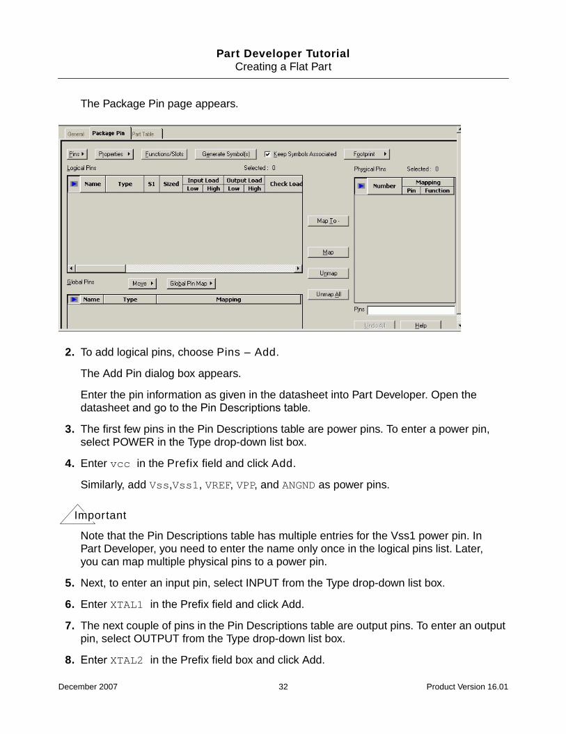
The Package Pin page appears.
2. To add logical pins, choose Pins – Add.
The Add Pin dialog box appears.
Enter the pin information as given in the datasheet into Part Developer. Open thedatasheet and go to the Pin Descriptions table.
3. The first few pins in the Pin Descriptions table are power pins. To enter a power pin,select POWER in the Type drop-down list box.
4. Enter vcc in the Prefix field and click Add.
Similarly, add Vss,Vss1, VREF, VPP, and ANGND as power pins.
Important
Note that the Pin Descriptions table has multiple entries for the Vss1 power pin. InPart Developer, you need to enter the name only once in the logical pins list. Later,you can map multiple physical pins to a power pin.
5. Next, to enter an input pin, select INPUT from the Type drop-down list box.
6. Enter XTAL1 in the Prefix field and click Add.
7. The next couple of pins in the Pin Descriptions table are output pins. To enter an outputpin, select OUTPUT from the Type drop-down list box.
8. Enter XTAL2 in the Prefix field box and click Add.
December 2007 32 Product Version 16.01
Part Developer TutorialCreating a Flat Part
Similarly, add P2.7 as an output pin.
9. RESET, the next pin in the table, is an active low input pin. To add an active low input pin,select INPUT from the Type drop-down list box.
10. Enter RESET in the Prefix field.
11. To make a pin active low, enter * in the Suffix field and click Add.
Similarly, add all the pins up to P6.3 specified in the Pin Descriptions table of thedatasheet.
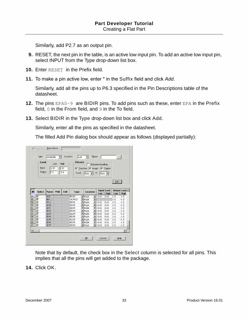
12. The pins EPA0-9 are BIDIR pins. To add pins such as these, enter EPA in the Prefixfield, 0 in the From field, and 9 in the To field.
13. Select BIDIR in the Type drop-down list box and click Add.
Similarly, enter all the pins as specified in the datasheet.
The filled Add Pin dialog box should appear as follows (displayed partially):
Note that by default, the check box in the Select column is selected for all pins. Thisimplies that all the pins will get added to the package.
14. Click OK.
December 2007 33 Product Version 16.01

Part Developer TutorialCreating a Flat Part
The pins appear in the Logical Pins grid of the Package Editor.
Next, you need to specify the physical pins. Physical pins can be entered in one of the twoways:
■ Manually
■ By specifying a footprint and then extracting the pins from the footprint
We will be using the second option to add the physical pins.
Specifying the Footprints
Task Overview
Specify the JEDEC_TYPE and ALT_SYMBOLS properties for the package.
Steps
1. Click on the General tab.
2. To specify the JEDEC_TYPE, click on the browse button next to the Jedec Type field inthe Associated Footprints group box.
December 2007 34 Product Version 16.01

Part Developer TutorialCreating a Flat Part
The Browse Jedec Type dialog box appears.
As you can see, this is a big list and you need to scroll down to get to the required data.To view only a select set of footprints, you can set filters.
Important
Filters can be set in any of the grids, such as Logical Pins, Physical Pins, and soon.
Setting a Filter
1. Right-click on any one of the rows in the Browse Jedec Type dialog box and select FilterRows.
December 2007 35 Product Version 16.01

Part Developer TutorialCreating a Flat Part
The Filter Rows dialog box appears.
2. Enter PLCC* in the Name column and click OK.
The Browse Jedec Type dialog box displays only the PLCC footprints.
3. Select plcc68 and click OK.
4. Similarly, select the Alt_Symbols for the part.
December 2007 36 Product Version 16.01

Part Developer TutorialCreating a Flat Part
Note: To remove filter, you need to right-click on the filtered grid and select the Unhide AllRows options.
Next, you will extract the physical pins from the footprint.
Entering Physical Pins
Task Overview
Extract physical pin information from the footprint.
Steps
1. Click on the Package Pin tab.
The Package Pin page appears.
2. Select Footprint – Extract from Footprint.
The Part Developer message box appears. This message box states that all physicalpins that exist in the package but are not available in the selected footprint will be deleted.
3. Because there are no existing physical pins, click Yes.
December 2007 37 Product Version 16.01

Part Developer TutorialCreating a Flat Part
The physical pins get extracted from the footprint and appear in the Physical Pins grid.Note that the pin numbers are not sorted.
4. To sort the physical pins, click on the Number column heading.
Note that the power pins are listed in the Logical Pins grid. This implies that when asymbol is generated from the package, the power pins will be visible in the symbol. Toavoid that, you need to move the pins to the Global Pins grid. The pin types that areconsidered global pins are as follows:
❑ POWER
❑ GROUND
❑ NC
Moving Pins from Logical Pins to Global Pins
Task Overview
Move the power pins to the Global Pins grid.
December 2007 38 Product Version 16.01
Part Developer TutorialCreating a Flat Part
Steps
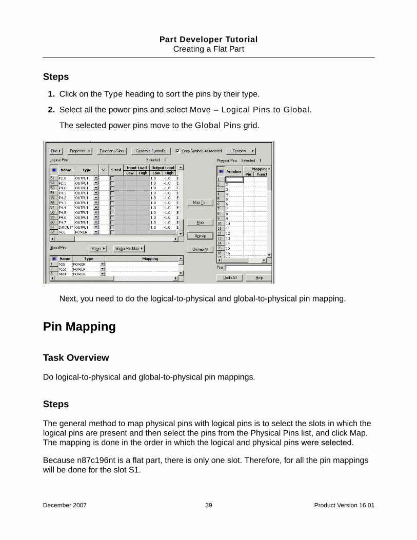
1. Click on the Type heading to sort the pins by their type.
2. Select all the power pins and select Move – Logical Pins to Global.
The selected power pins move to the Global Pins grid.
Next, you need to do the logical-to-physical and global-to-physical pin mapping.
Pin Mapping
Task Overview
Do logical-to-physical and global-to-physical pin mappings.
Steps
The general method to map physical pins with logical pins is to select the slots in which thelogical pins are present and then select the pins from the Physical Pins list, and click Map.The mapping is done in the order in which the logical and physical pins were selected.
Because n87c196nt is a flat part, there is only one slot. Therefore, for all the pin mappingswill be done for the slot S1.
December 2007 39 Product Version 16.01

Part Developer TutorialCreating a Flat Part
For global-to-physical pin mapping, you need to select the required global pins andcorresponding physical pins, and click Map. It is possible to map one global pin to more thanone physical pin.
1. As per the datasheet, physical pin 1 is mapped to logical pin P5.4. Therefore, select 1 inthe Physical Pins list and slot S1 for logical pin P5.4 in the Logical Pins list, and clickMap.
The physical pin 1 is mapped to the logical pin P5.4.
Next, we will map multiple pins in a single step.
2. Select the slots next to pins P5.6, P5.1, and P5.0 and then select physical pins 2,3, and4 and click Map. The pins get mapped in the order in which the slots were selected.
The next two physical pins are mapped to power pins.
Important
Unlike logical pins, global pin mapping can be done for only one pin at a time. Thisis because one global pin can be mapped to multiple physical pins.
3. Select VSS in the Global Pins grid and 5 in the Physical Pins grid and click Map.
As you do the pin mappings, the logical and the physical pins grid will keep getting filledup. This can be disconcerting when dealing with a large number of pins. Using an RMBoption, you can configure Part Developer to hide the mapped pins.
Hiding Mapped Pins
Task Overview
Hide the mapped pins.
Steps
1. Right-click on the Logical Pins grid and select Hide Mapped Pins.
2. Right-click on the Physical Pins grid and select Hide Mapped Pins.
The mapped pins are hidden from the Logical and Physical Pins grids. You may do thisas many number of times as required.
December 2007 40 Product Version 16.01

Part Developer TutorialCreating a Flat Part
Important
The first header of a grid provides a visual indication of whether all the rows andcolumns are displayed in the grid. If all the rows/columns are visible, the filter viewerappears in blue. In case some rows and columns are hidden, the viewer appears ingreen.
Continuing Pin Mapping
1. Complete the pin mapping by following the methods mentioned above.
2. Save the part.
Next, you will create the symbol.
Creating Symbols
A symbol represents a unique function group in a package. There are multiple ways to createsymbols for a package.
1. Use the Generate Symbols pop-up menu option in the cell tree on the package nameor the function group.
2. Use the Generate Symbol(s) button on the Package Pin page of the Package Editor.
Task Overview
Create the symbol using the Generate Symbol(s) button in the Package Pin page of thePackage Editor.
Steps
1. Click Generate Symbol(s).
December 2007 41 Product Version 16.01

Part Developer TutorialCreating a Flat Part
The Generate Symbol(s) for Package N87C196NT dialog box appears.
2. Click OK.
The symbol is created and appears in the cell tree.
3. To view the symbol, click on sym_1.
Symbol
December 2007 42 Product Version 16.01

Part Developer TutorialCreating a Flat Part
The symbol details appear in the Symbol Pins panel and the symbol graphics are shownon the Symbol Editor canvas.
Summary
This completes the task of creating a single-slot flat part.
December 2007 43 Product Version 16.01
Part Developer Tutorial
4Creating Parts from CSV Files
Objective
To become familiar with the steps in creating parts by importing data from a CSV file.
In this chapter, you will:
■ Understand the CSV file format from which data can be imported into Part Developer
■ Import data from a CSV file
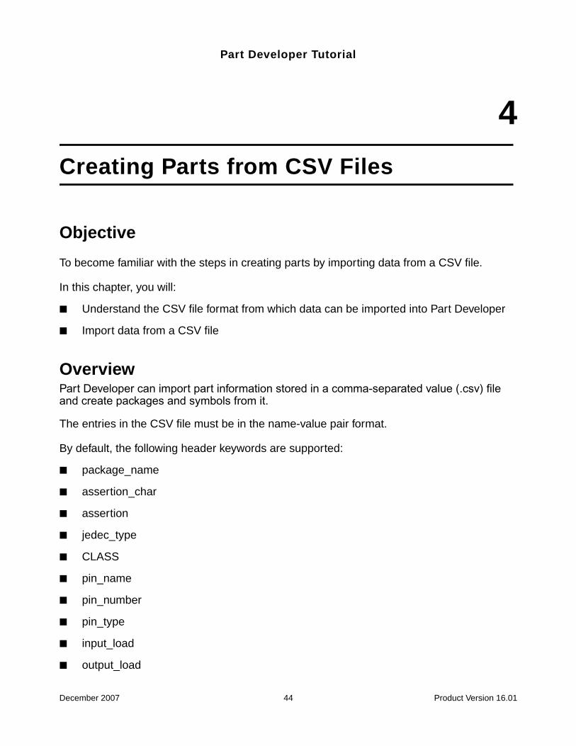
OverviewPart Developer can import part information stored in a comma-separated value (.csv) fileand create packages and symbols from it.
The entries in the CSV file must be in the name-value pair format.
By default, the following header keywords are supported:
■ package_name
■ assertion_char
■ assertion
■ jedec_type
■ CLASS
■ pin_name
■ pin_number
■ pin_type
■ input_load
■ output_load
December 2007 44 Product Version 16.01

Part Developer TutorialCreating Parts from CSV Files
■ pin_location
■ pin_position
■ load_setupfile
Important
The minimum of headers required are as follows:
❑ pin_name and pin_number for flat parts
❑ pin_name, pin_number, and symbol for multi-section parts
Important
If required, these header keywords can be changed to your specifications. See theConfiguring the Pre-Defined Headers for CSV Import section in the AdvancedTasks chapter in the Part Developer User Guide.
The CSV File Format
The package and symbol information is determined in the following way:
■ The package_name entry is used to derive the name of the package. If this entry ismissing, the cell name is used for the package name. You can create equivalentpackages (aliases) by specifying comma-separated values, such as 7400_DIP,7400_CCC, and so on.
■ The assertion_char entry is used to determine which pins will be treated as low-asserted. If this entry is present, the values specified in the Read/Write and AdditonalRead fields in Setup are ignored.
■ The assertion entry is used to determine whether a pin is low-asserted or not. Thevalues that will determine the low assertion are specified using theImport_Csv_LowassertFlag directive. By default, the values L and Low arespecified.
■ The jedec_type entry is used to determine the value of the JEDEC_TYPE property.
■ The CLASS entry is used to determine the value of the CLASS property.
■ The load_setupfile entry is used to determine the location of the project file fromwhich to read the setup values. The setup values of the current project will be ignored.
■ Entries under the pin_name column are used as pin names.
December 2007 45 Product Version 16.01

Part Developer TutorialCreating Parts from CSV Files
■ Entries under the pin_number column are used as pin numbers.
■ Entries under the pin_type column are used as pin types.
■ Entries under the output_load column are used as the output load values for a pintype.
■ Entries under the pin_location column are used to determine the pin location forspecific pin types.
■ Symbols are created only if the symbol entry is present in the header line that describesthe pins.
■ Entries under the pin_position field determines the position of the pin from the origin.This will appear as the value of the Position property in the Symbol Editor.
■ All name-value pair entries before the pin_number, pin_name, pin_type, andsymbol headings are imported as additional package properties.
Importing Data from a CSV File
The pentium4_3Ghz.csv file in the <your_inst_dir>/doc/pdv_tut/tutorial_data/datasheets location will be used in this chapter to demonstrate thesteps involved in importing data from a CSV file.
December 2007 46 Product Version 16.01

Part Developer TutorialCreating Parts from CSV Files
A part of the CSV file is displayed below:
As displayed, the CSV file has the following fields:
■ pin_name
■ pin_type
■ pin_number
■ a pin property called signal_description
Note: The signal_description property is not used by any downstream tools. It has beenused in the tutorial to demonstrate some of the features of Part Developer.
You will now import the CSV file and create the part.
Task Overview
Import the pentium3_4GHz.csv file into Part Developer.
December 2007 47 Product Version 16.01

Part Developer TutorialCreating Parts from CSV Files
Steps
1. Choose File – Import and Export.
The Import and Export wizard appears.
2. Choose Import Comma Separated Value (.csv) file and click Next.
The Select Source page appears.
3. Browse to the <your_inst_dir>\doc\pdv_tut\tutorial_data\datasheetslocation and open the pentium4_3GHz.csv file.
4. Click Next.
The Select Destination page appears.
5. The names of the cell and destination library are seeded by default. The name of the cellis the same as that of the CSV file.
6. Click Next.
The Preview of Import Data page appears. This page gives you a preview of the part thatis being created from the CSV data.
7. Click Finish.
December 2007 48 Product Version 16.01

Part Developer TutorialCreating Parts from CSV Files
The part is created and loaded in the Cell Editor.
8. Select the PENTIUM4_3GHZ package in the cell tree.
The Package Editor loads the package.
9. Click on the General tab.
December 2007 49 Product Version 16.01

Part Developer TutorialCreating Parts from CSV Files
The General page appears.
Note that the BODY_NAME entry in the CSV file appears as a package property. Alsonote that the LIBRARY_NAME and PACKAGE_CREATOR properties, which were addedin Setup in the previous chapter, also get added to the package.
10. Click on the Package Pin tab.
From CSV
FromSetup
December 2007 50 Product Version 16.01

Part Developer TutorialCreating Parts from CSV Files
The Package Pin page appears.
Note that the pin names, types, and mappings are added as specified in the CSV file.
Next, you will ensure that the SIGNAL_DESCRIPTION pin property has also beenadded.
11. Right-click anywhere in the Logical Pins grid and select Hide Load Cols.
December 2007 51 Product Version 16.01

Part Developer TutorialCreating Parts from CSV Files
The load columns get hidden, and you can see the SIGNAL_DESCRIPTION property.
12. Save the part.
Summary
In this chapter, you learned about importing data from a CSV file to create a part.
December 2007 52 Product Version 16.01
Part Developer Tutorial
5Creating Split Parts
Objective
To become familiar with the steps in creating split parts.
In this chapter, you will learn:
■ About the methodology for creating split parts
■ How to create a split part by adding multiple slots
■ How to create symbols for each slot
Overview
Parts are typically split for reasons such as:
■ To reflect the way part functionality is used in a schematic.
■ To display large pin-count parts better.
Methodology for Creating Split Parts
The following methodology should be followed for creating split parts:
1. Decide whether to use the SPLIT_INST and $LOCATION properties or theSPLIT_INST_NAME property for the split part.
2. Create the package with a single slot.
3. Do the logical-to-physical pin mapping for the first slot.
4. Create the necessary slots.
5. Distribute the pins across the slots.
December 2007 53 Product Version 16.01
Part Developer TutorialCreating Split Parts
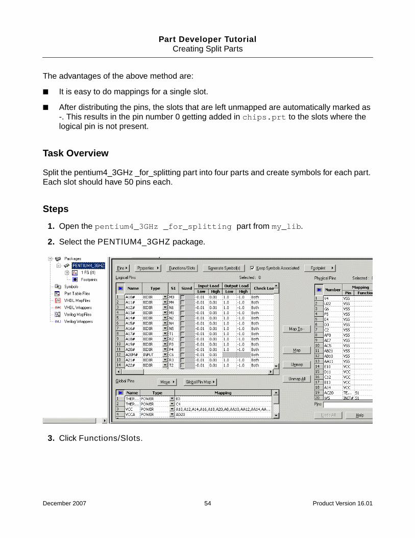
The advantages of the above method are:
■ It is easy to do mappings for a single slot.
■ After distributing the pins, the slots that are left unmapped are automatically marked as-. This results in the pin number 0 getting added in chips.prt to the slots where thelogical pin is not present.
Task Overview
Split the pentium4_3GHz _for_splitting part into four parts and create symbols for each part.Each slot should have 50 pins each.
Steps
1. Open the pentium4_3GHz _for_splitting part from my_lib.
2. Select the PENTIUM4_3GHZ package.
3. Click Functions/Slots.
December 2007 54 Product Version 16.01

Part Developer TutorialCreating Split Parts
The Edit Functions dialog box appears.
4. Enter 1 in the SPLIT_INST_GROUP field. The SPLIT_INST_GROUP property is usedfor split parts. The value enables Part Developer to determine which slots of a split partcombine to form one logical group.
5. To add more slots, click Add.
The Specify the number of slots dialog box appears.
6. To create three more slots, type 3 in the Slot Count field and click OK.
December 2007 55 Product Version 16.01

Part Developer TutorialCreating Split Parts
The four slots are created.
Next, you need to distribute the pins across the four slots.
7. Click Distribute Pins.
December 2007 56 Product Version 16.01

Part Developer TutorialCreating Split Parts
The Distribute Pins dialog box appears.
By default, all the 199 logical pins are present in the first slot. You need to distribute thesepins across the four slots.
8. Select the cells 51-100 under S1.
9. Right-click on the selection and choose Move To.
The Move To Function dialog box appears.
This dialog box displays all the slots other than the slot from which it has been called.
10. To move the pins to the second slot, click OK.
December 2007 57 Product Version 16.01
Part Developer TutorialCreating Split Parts
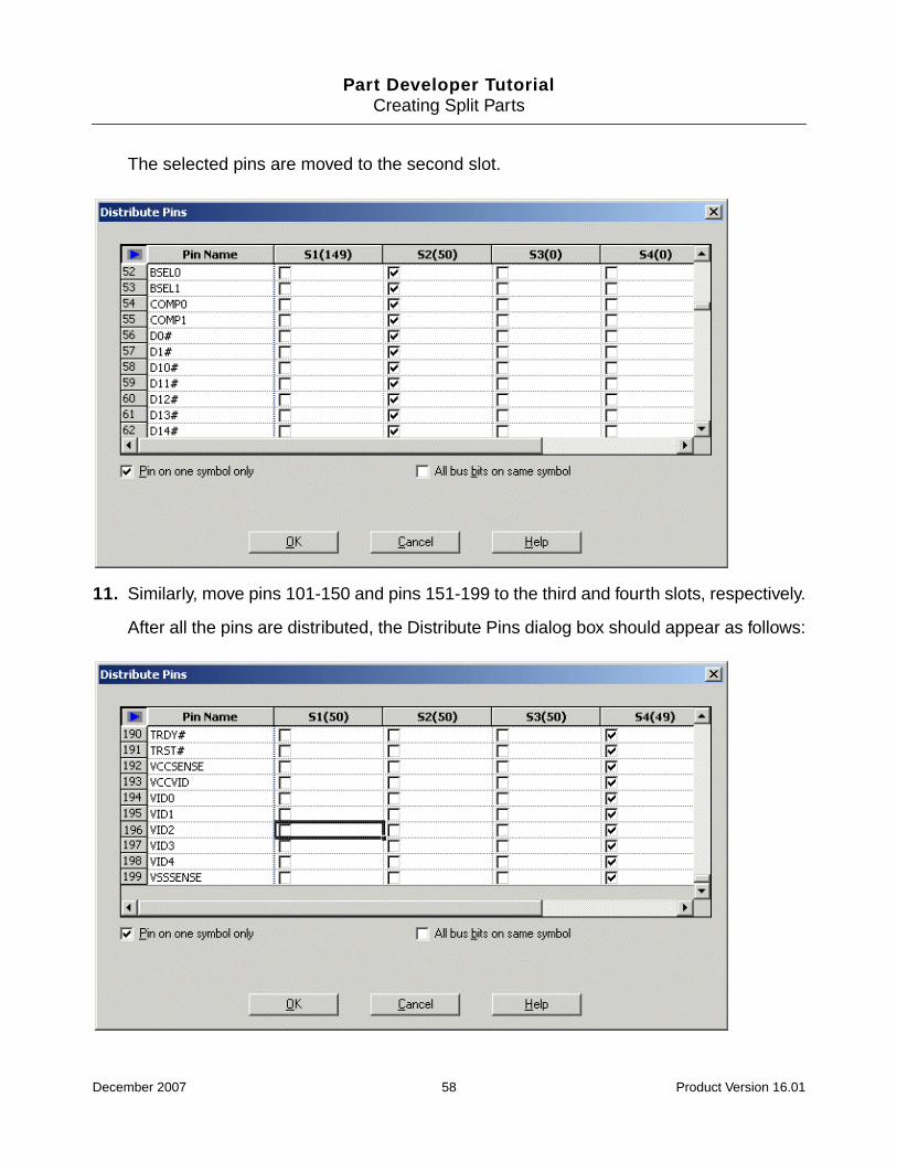
The selected pins are moved to the second slot.
11. Similarly, move pins 101-150 and pins 151-199 to the third and fourth slots, respectively.
After all the pins are distributed, the Distribute Pins dialog box should appear as follows:
December 2007 58 Product Version 16.01

Part Developer TutorialCreating Split Parts
12. Click OK.
The pins are distributed across the four slots. The slots in which a logical pin is notpresent is mapped to -.
Next, you will create the symbols for the four slots.
13. Click Generate Symbol(s).
December 2007 59 Product Version 16.01

Part Developer TutorialCreating Split Parts
The Generate Symbol(s) for Package PENTIUM4_3GHZ dialog box appears.
14. To create symbols for all functions, click OK.
The symbols are created for all the function groups.
December 2007 60 Product Version 16.01

Part Developer TutorialCreating Split Parts
Summary
In this chapter, you learned how to create split parts.
December 2007 61 Product Version 16.01

Part Developer TutorialCreating Parts from PDFs
6Creating Parts from PDFs
Objective
To become familiar with the steps involved in creating parts from PDFs.
In this chapter, you will learn to:
■ Enter pin information directly from a PDF file to the Logical Pins grid in the PackageEditor.
■ Use a spreadsheet to manipulate pin information and then use it to create parts.
Overview
Part Developer helps you create parts from datasheets available in the PDF format. From thedatasheet, you can do a text-copy of pin information and paste directly into the Logical andPhysical Pins grid.
Creating Parts from PDFs
Task Overview
Create the part from the Pentium datasheet (24919805.pdf) located in<your_inst_dir>\doc\pdv_tut\tutorial_data\datasheets.
Pentium Datasheet
Given below is the relevant portion from the datasheet of the Pentium processor. Note thatonly the partial pin list is displayed.
December 2007 62 Product Version 16.01
Part Developer TutorialCreating Parts from PDFs
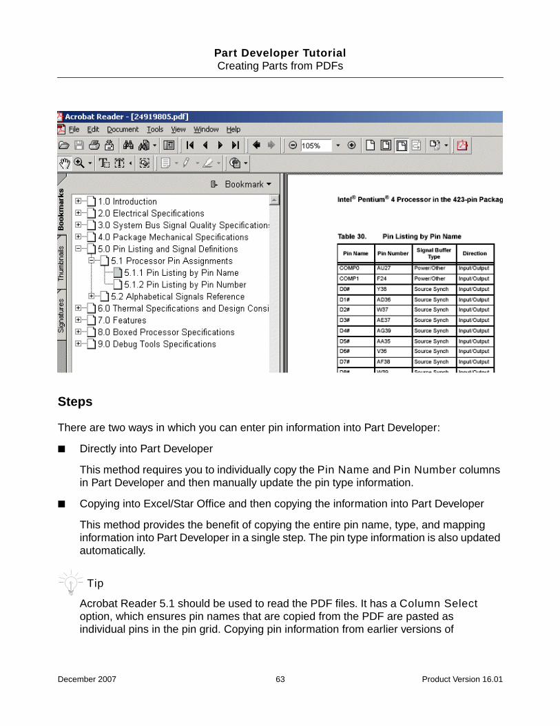
Steps
There are two ways in which you can enter pin information into Part Developer:
■ Directly into Part Developer
This method requires you to individually copy the Pin Name and Pin Number columnsin Part Developer and then manually update the pin type information.
■ Copying into Excel/Star Office and then copying the information into Part Developer
This method provides the benefit of copying the entire pin name, type, and mappinginformation into Part Developer in a single step. The pin type information is also updatedautomatically.
Tip
Acrobat Reader 5.1 should be used to read the PDF files. It has a Column Selectoption, which ensures pin names that are copied from the PDF are pasted asindividual pins in the pin grid. Copying pin information from earlier versions of
December 2007 63 Product Version 16.01

Part Developer TutorialCreating Parts from PDFs
Acrobat Reader results in all the pin names appearing as a single pin name in theLogical Pins grid. To fix this, use the Edit – Paste Special(Grid) – ConvertWhitespaces to NewLine option when pasting data into Part Developer.
Directly into Part Developer
1. Open the datasheet in Acrobat Reader.
2. Select the Column Select Tool option.
3. Select the Pin Name column and press Ctrl + C.
4. Launch Part Developer and create a new part and package.
5. Go to the Package Pin page of the Package Editor.
6. Press Ctrl + I to insert a new row in the Logical Pins grid.
7. Select the empty cell under the Name column and press Ctrl + V to paste the pin namesinto the Logical Pins grid.
The pin names appear under the Name column.
Next, you need to copy the pin numbers that are mapped to the pin names.
8. Select the Pin Number column in the datasheet and press Ctrl + C.
9. Select the first cell under the S1 column and press Ctrl + V.
December 2007 64 Product Version 16.01

Part Developer TutorialCreating Parts from PDFs
The physical pin numbers are copied into the Logical Pins grid. The Physical Pins gridis also updated automatically with the pin-mapping information.
Next, you need to copy the direction information from the PDF into the Type column todetermine the pin types. In case the direction is missing in the PDF, you will need tomanually determine the pin type in Part Developer.
10. Select the Direction column in the datasheet and press Ctrl + C.
11. Select the first cell under the Type column and press Ctrl + V.
Note that in the datasheet, the direction of the pins were Input/Output. However, oncopying, the pin type is changed to BIDIR. This automatic translation is handled throughthe entries in the propfile.prop file located at<your_inst_dir>\share\cdssetup\LMAN. For more information, see theAdvanced Tasks chapter in the Part Developer User Guide.
Copying First into Excel/Star Office and then into Part Developer
1. Open the datasheet in Acrobat Reader.
2. Select the Column Select Tool option.
December 2007 65 Product Version 16.01

Part Developer TutorialCreating Parts from PDFs
3. Select the Pin Name column and press Ctrl + C.
4. Open an Excel or Star Office spreadsheet and press Ctrl + V to paste the data in the firstcolumn.
5. Next, copy the Direction and Pin Number columns and paste into the columns adjacentto the pin names column.
The filled spreadsheet should appear like the one displayed below:
6. Select the three columns in the spreadsheet and press Ctrl + C.
7. Press Ctrl + I to insert a blank row in the Logical Pins grid.
8. Select the empty cell under the Name column in Logical Pins grid and press Ctrl + V.
The pin information along with the pin type and the mapping information is copied intothe Logical Pins grid. The Physical Pins grid is also updated automatically. Note thatthe Input/Output pin type is automatically converted to the BIDIR type in theLogical Pins grid. This translation is controlled through the propfile.prop filelocated at <your_inst_dir>\share\cdssetup\LMAN. For more information, seethe Advanced Tasks chapter in the Part Developer User Guide.
December 2007 66 Product Version 16.01

Part Developer TutorialCreating Parts from PDFs
Caution
When copying data from PDFs, invalid characters in pin names need to befixed manually. Part Developer will generate errors if an attempt is madeto save a part with invalid characters in pin names.
Summary
In this chapter, you learned to create parts from PDF datasheets.
December 2007 67 Product Version 16.01

Part Developer TutorialCreating Asymmetrical Parts
7Creating Asymmetrical Parts
Objective
To become familiar with steps involved in creating asymmetrical parts.
In this chapter, you will learn to:
■ Use the Package Editor to enter pin information.
■ Specify pin information for multiple slots.
■ Create symbols for each slot group.
Overview
An asymmetrical part is a part in which multiple functions are present in a package. Forexample, LS241, an 8-slot part, with two different functions, is an asymmetrical part. Thischapter teaches you how to create LS241. By following the steps detailed here, you cancreate asymmetrical parts.
Understanding the LS241 Part
December 2007 68 Product Version 16.01

Part Developer TutorialCreating Asymmetrical Parts
As displayed, LS241 is an 8-slot part with a low-asserted enable signal (1OE*) and a high-asserted enable signal (2OE). The high-asserted enable signal 2OE is present in four slotsand the low-asserted enable signal 1OE* is present in the remaining four. This divides thepart into two groups. The first group has 2OE as the enable pin and the second group has1OE* as the enable pin. Because the functionality of each slot in a group is the same andbecause of the different assertion signals across the slots, the logical pin lists for the sectionsor slots are different.
Task Overview
Do the following:
■ Create the LS241 part in the my_lib library.
■ Create a package.
■ Enter the pin information through the Package Editor.
■ Create symbols for the different slot groups.
Steps
1. Select File – New – Cell.
The New Cell dialog box appears.
December 2007 69 Product Version 16.01

Part Developer TutorialCreating Asymmetrical Parts
2. Select the my_lib library.
3. Enter ls241 in the Cell field and click OK.
The Cell Editor appears with the empty LS241 part.
4. Right-click on the Packages entry in the cell tree and select New.
A new package, LS241, is created and loaded in the Package Editor.
5. Right-click in the Logical Pins grid on the Package Pin page and select Insert RowAfter.
A blank row is created.
Because LS241 has eight slots, you will need to create eight slots.
6. To create eight slots, click Functions/Slots.
The Edit Functions dialog box appears.
Since slot S1 already exists, you will need to add seven more slots.
7. Click Add, specify 7 in the Specify the number of slots dialog box, and click OK.
8. Click OK to close the Edit Functions dialog box.
Next, you will enter the pins.
9. Enter 1OE* in the Name column.
10. Because the pin is of type input, select INPUT from the Type drop-down list.
Now, the pin 1OE* is common across the four slots.
December 2007 70 Product Version 16.01

Part Developer TutorialCreating Asymmetrical Parts
11. Since 1OE* is mapped to physical pin 1, enter 1 in the S1, S2, S3, and S4 columns.
12. Since 1OE* is not present in the remaining four slots, select slots S5 to S8 and click MapTo -.
This maps the selected slots to -.
13. To add another row, press Ctrl + I.
A new row gets added to the Logical Pins grid.
14. Enter 1A in the Name column.
15. Select INPUT from the Type drop-down list.
16. Since 1A is present in the first 4 slots and mapped to the physical pins 2,4, 6 and 8, enter2, 4, 6, and 8 under S1, S2, S3, and S4, respectively.
17. Select the slots S5 to S8 for pin 1A, and click Map To -.
18. To add another row, press Ctrl + I.
A new row gets added to the Logical Pins grid.
19. Enter 1Y in the Name column.
20. Select OUTPUT from the Type drop-down list.
21. Since 1Y is present in the first 4 slots and mapped to physical pins 18,16, 14, and 12,enter 18,16, 14, and 12 under S1, S2, S3, and S4, respectively.
22. Select the slots S5 to S8 for pin 1Y and click Map To -.
Similarly, enter the remaining pins.
December 2007 71 Product Version 16.01
Part Developer TutorialCreating Asymmetrical Parts
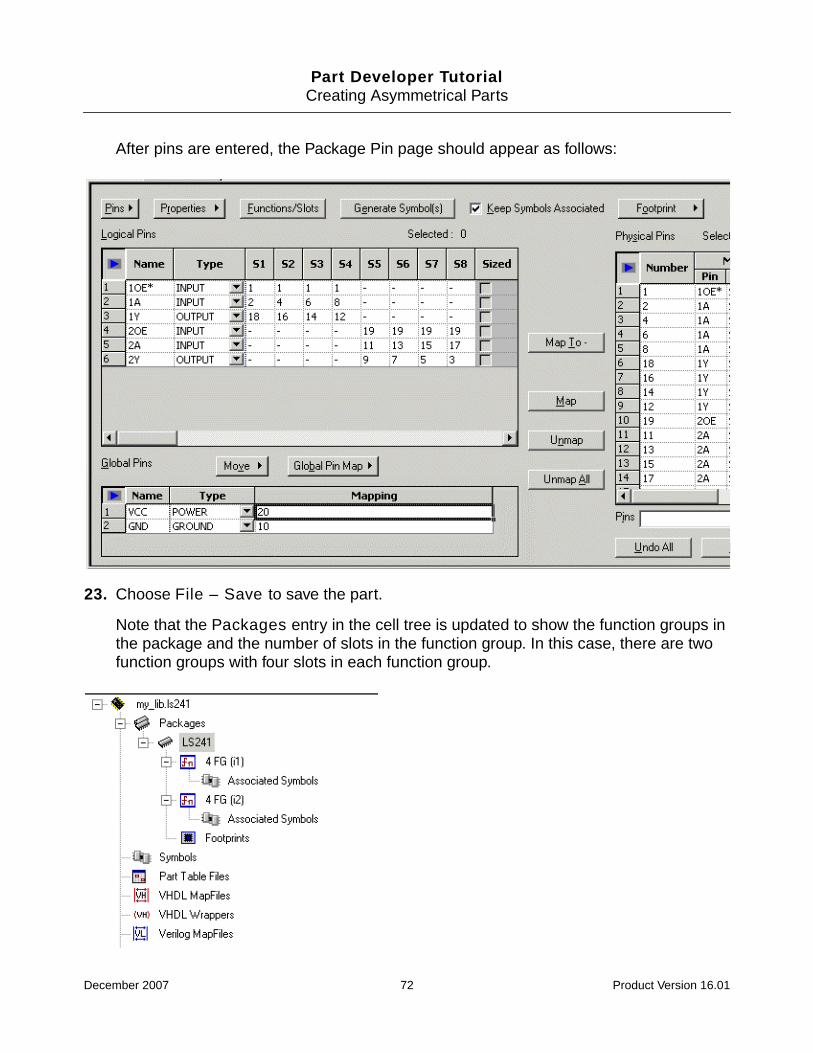
After pins are entered, the Package Pin page should appear as follows:
23. Choose File – Save to save the part.
Note that the Packages entry in the cell tree is updated to show the function groups inthe package and the number of slots in the function group. In this case, there are twofunction groups with four slots in each function group.
December 2007 72 Product Version 16.01
Part Developer TutorialCreating Asymmetrical Parts
Next, you will create a symbol for each function group.
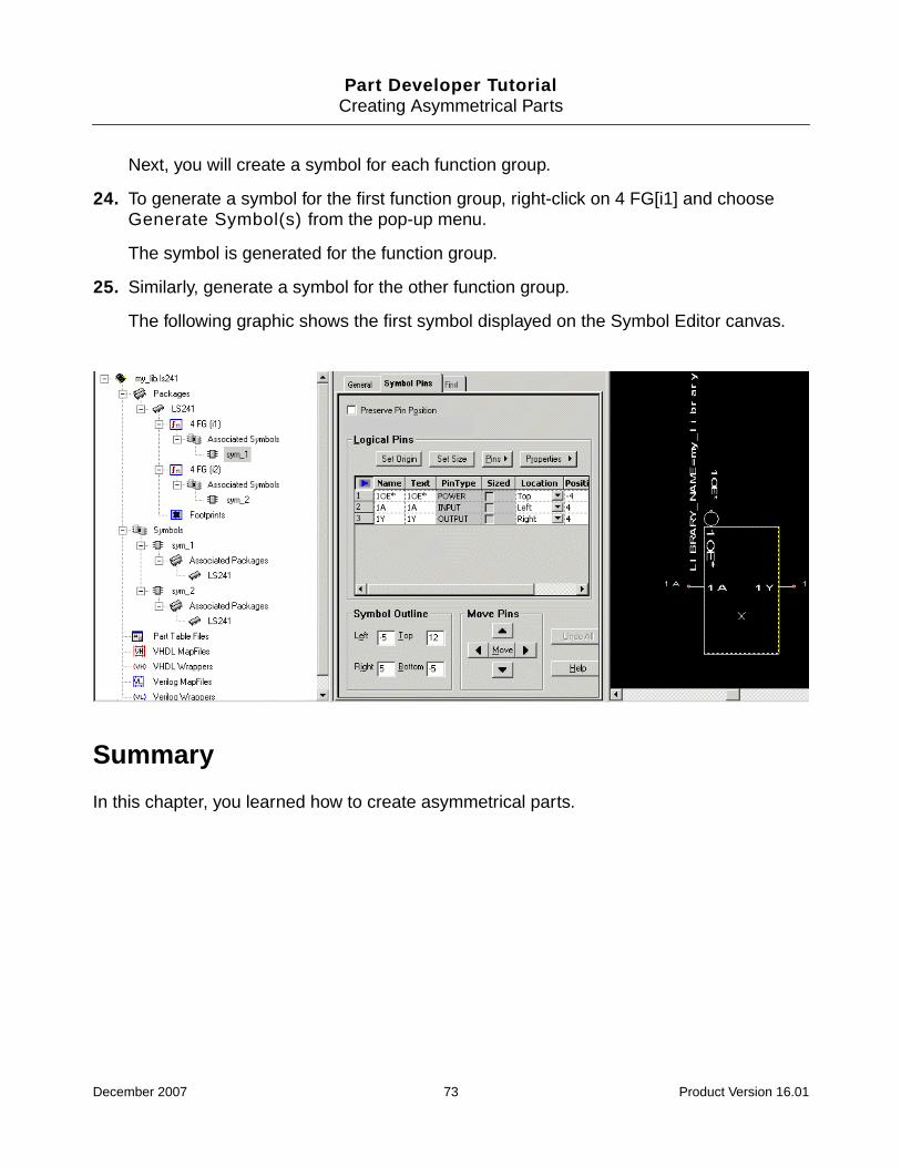
24. To generate a symbol for the first function group, right-click on 4 FG[i1] and chooseGenerate Symbol(s) from the pop-up menu.
The symbol is generated for the function group.
25. Similarly, generate a symbol for the other function group.
The following graphic shows the first symbol displayed on the Symbol Editor canvas.
Summary
In this chapter, you learned how to create asymmetrical parts.
December 2007 73 Product Version 16.01

Part Developer TutorialWorking with Differential Pairs
8Working with Differential Pairs
Objective
To become familiar with the steps in adding and removing differential pair information in PartDeveloper.
In this chapter, you will learn to:
■ Autocreate differential pairs in all cells of a library
■ Autocreate differential pairs through the Package Editor
■ Create a differential pair from selected pins
■ Remove differential pair properties from a differential pair
Overview
When creating parts in Part Developer, you can capture differential pair information fromdatasheets. If you have legacy libraries without differential pair information, you can run abatch utility and create differential pairs based on specified differential pair recognition rules.This chapter covers various ways of creating differential pairs and the procedure for removingdifferential pair information.
To try the various procedures described in this chapter, you will use the project dp_proj andthe library dp_proj_lib in the library_project folder at <your_inst_dir>/doc/pdv_tut/tutorial_data. Make sure that you have copied the library_projectfolder to <your_work_area>.
Points to Remember about Differential Pair Support in Part Developer
■ The differential pair property is associated with logical pins.
■ The positive and negative pins comprising a differential pair must have the same pintype.
December 2007 74 Product Version 16.01
Part Developer TutorialWorking with Differential Pairs
■ The differential pair property cannot be associated with GROUND, POWER, and NC pintypes.
■ The differential pair property is saved in chips only.
Autocreating Differential Pairs in All Cells of a Library
Add differential pair information to all parts in the dp_lib library based on the followingdifferential pair recognition rule:
DiffPair_Recognition_Rules ’n:SUFFIX,p:SUFFIX;-:SUFFIX,+:SUFFIX;_L:SUFFIX,_H:SUFFIX;_LOW:SUFFIX,_HIGH:SUFFIX;_N:SUFFIX,_P:SUFFIX’
The task involves the following subtasks:
1. Configuring the default differential pair recognition rule in your local project file to add thenaming scheme _N:SUFFIX,_P:SUFFIX
2. Configuring the low assertion setup in Part Developer to disallow the use of the _N suffix
3. Running the con2con utility on the dp_lib library with the autocreatediffpairoption
Configuring the Default Differential Pair Recognition Rule for a Project
To configure the default differential pair recognition rule for a project, you need to copy theDiffPair_Recognition_Rules definition from the installation CPM file (cds.cpm) or the siteCPM file (setup.cpm) to the project file. For the task at hand, the default differential pairrecognition rule has been added from cds.cpm to the project file dp_proj.cpm.
December 2007 75 Product Version 16.01

Part Developer TutorialWorking with Differential Pairs
1. Open the dp_proj.cpm project in a text editor.
Notice that the default DiffPair_Recognition_Rules definition does not include thenaming scheme _N:SUFFIX,_P:SUFFIX.
2. To add the naming scheme, click before the closing ’ character, type the following:
;_N:SUFFIX,_P:SUFFIX
The differential pair recognition rule is modified to:
DiffPair_Recognition_Rules ’n:SUFFIX,p:SUFFIX;-:SUFFIX,+:SUFFIX;_L:SUFFIX,_H:SUFFIX;_LOW:SUFFIX,_HIGH:SUFFIX;_N:SUFFIX,_P:SUFFIX’
3. Save and close the project file.
Configuring the Low Assertion Setup to Disallow the Use of the _N Suffix
By default, Part Developer considers pin names with the _N suffix as low-asserted pins.Therefore, you need to modify the default low assertion setup if you want Part Developer touse the _N suffix to identify negative pins of differential pairs.
1. Choose File – Open Project.
2. Click the Browse button to select the dp_proj.cpm project file from thelibrary_project folder and click Open.
3. Click OK.
4. Choose Tools – Setup.
December 2007 76 Product Version 16.01

Part Developer TutorialWorking with Differential Pairs
5. Click on the down arrow button in the Additional Read list box.
6. Select *.
7. Click OK.
Running the con2con Utility on a Library with the autocreatediffpairOption
After you have configured the differential pair recognition rule according to your requirements,you can run the con2con utility with the autocreatediffpair option to add differentialpair information to libraries in batch mode. For the task at hand, you will add differential pairinformation to all parts in the dp_lib library.
To run the con2con utility on the dp_lib library with the autocreatediffpair option:
December 2007 77 Product Version 16.01

Part Developer TutorialWorking with Differential Pairs
➤ Type the following command at the command prompt:
con2con -product pcb_librarian_expert -proj <your_work_area>/library_project/dp_proj.cpm -cdslib <your_work_area>/library_project/cds.lib -libdp_proj_lib -autocreatediffpair
Important
In the specified con2con command, <your_work_area> is the location where youhave copied the library_project folder from <your_inst_dir>/doc/pdv_tut/tutorial_data to try the procedures detailed in this tutorial.
Autocreating Differential Pairs through the PackageEditor
The dp_proj_lib library contains parts with differential pair properties. If you add new partsto this library, you can add differential pair properties only to a selected part through thePackage Editor.
Create a part, dp_part_3, in the dp_proj_lib library with the following pin information inpackages DP_PART_3 and DP_PART_3_1:
For information on how to create a part, see the Creating a Flat Part chapter.
Pin Name Pin Number Pin Type
DATA_L<4..0> 1,2,3,4,5 INPUT
DATA_H<4..0> 6,7,8,9,10 INPUT
AS1- 11 ANALOG
AS1+ 12 ANALOG
-RD 13 OUTPUT
+RD 14 OUTPUT
VCC 15 POWER
GND 16 GROUND
December 2007 78 Product Version 16.01
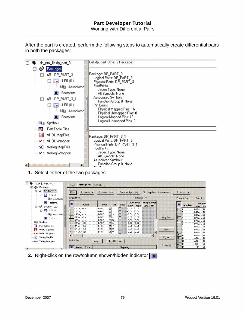
Part Developer TutorialWorking with Differential Pairs
After the part is created, perform the following steps to automatically create differential pairsin both the packages:
1. Select either of the two packages.
2. Right-click on the row/column shown/hidden indicator .
December 2007 79 Product Version 16.01
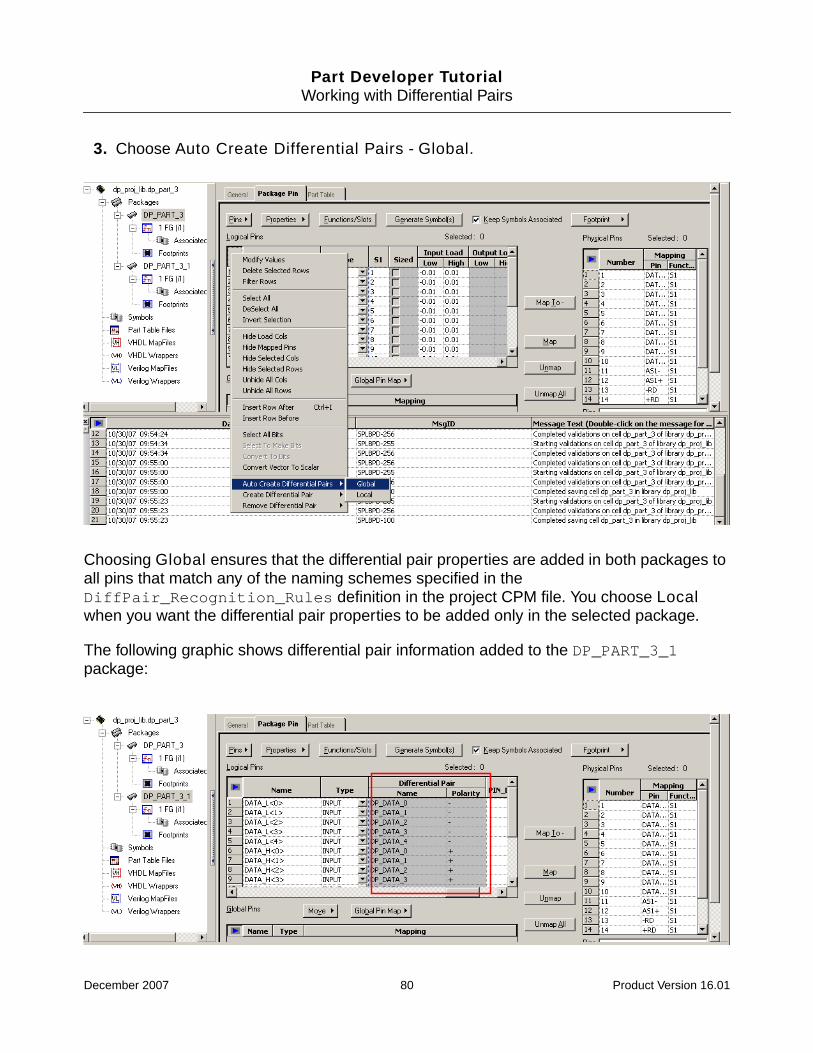
Part Developer TutorialWorking with Differential Pairs
3. Choose Auto Create Differential Pairs - Global.
Choosing Global ensures that the differential pair properties are added in both packages toall pins that match any of the naming schemes specified in theDiffPair_Recognition_Rules definition in the project CPM file. You choose Localwhen you want the differential pair properties to be added only in the selected package.
The following graphic shows differential pair information added to the DP_PART_3_1package:
December 2007 80 Product Version 16.01

Part Developer TutorialWorking with Differential Pairs
Creating a Differential Pair from Selected Pins
Typically, you select two pins that should constitute a differential pair and choose CreateDifferential Pair from the shortcut (RMB) menu in the following situations:
■ You have added new pins to a part that already has differential pair information forexisting pins.
■ You want to create a differential pair even if the names of the constituent pins do notfollow any of the naming schemes specified in the DiffPair_Recognition_Rulesdefinition.
For the task at hand, you will create a differential pair of the +RD and -RD pins only in theDP_PART_3_1 package.
1. Select the DP_PART_3_1 package.
2. Select the pins +RD and -RD.
The names of the selected pins do not follow any of the rules specified through theDiffPair_Recognition_Rules directive. In this case, Part Developer uses the orderof selection to identify positive and negative pins. The first pin selected is considered thepositive pin while the next pin selected is considered negative.
3. Right-click on the selection and choose Create Differential Pair – Local.
December 2007 81 Product Version 16.01

Part Developer TutorialWorking with Differential Pairs
The Differential Pair Name dialog box appears.
The Name field displays a name for the differential pair that Part Developer derives byadding the prefix or suffix specified in the Default_Diffpair_Value directive incds.cpm to the basenames of the pin. In the current scenario, the Name field displaysonly the Default_Diffpair_Value directive value because the selected pins do notfollow any of the rules specified through the DiffPair_Recognition_Rulesdirective.
For more information, see the Naming Differential Pairs section of the Creating Partschapter of Part Developer User Guide.
4. Specify the differential pair name as DP_RD.
5. Click OK to save the modified differential pair name.
The differential pair information is added to pins +RD and -RD.
December 2007 82 Product Version 16.01

Part Developer TutorialWorking with Differential Pairs
Removing Differential Pair Properties from a DifferentialPair
Remove differential pair information from the differential pair AS1 in the DP_PART_3 package.
1. Select any of the two pins AS1+ and AS1-.
2. Right-click on the selection and choose Remove Differential Pair – Local.
The differential pair information is removed from both pins.
Summary
In this chapter, you learned how to create differential pairs according to your requirementsand remove differential pair properties from packages.
December 2007 83 Product Version 16.01

Part Developer TutorialCreating Sizeable and HAS_FIXED_SIZE Symbols
9Creating Sizeable and HAS_FIXED_SIZESymbols
Objective
To become familiar with steps involved in creating sizeable and HAS_FIXED_SIZE symbols.
In this chapter, you will learn:
■ About the methodology in creating sizeable and HAS_FIXED_SIZE symbols
■ How to create a sizeable symbol
■ How to create a HAS_FIXED_SIZE symbol
Overview
You will create the LS00 part to understand the steps involved in creating sizeable parts. Thepin information is displayed below:
December 2007 84 Product Version 16.01

Part Developer TutorialCreating Sizeable and HAS_FIXED_SIZE Symbols
Methodology
The following needs to be done to create sizeable and HAS_FIXED_SIZE symbols:
1. Create a symbol through the Symbol Editor and add the sizeable pins.
2. Create packages.
3. Create the necessary slots.
4. Create sym_2 by making a copy of sym_1.
5. Specify the value of the SIZE property on the basis of the number of slots in sym_2. Thiswill add the HAS_FIXED_SIZE property to sym_2.
Caution
Do not specify the value of the SIZE property in the first symbol as it mayresult in an incorrect generation of the entity view.
Task Overview
Create the LS00 part in the my_lib library and create sizeable and HAS_FIXED_SIZEsymbols.
Steps
1. Choose File – New – Cell.
The New Cell dialog box appears.
2. Select the my_lib library.
3. Enter ls00 in the Cell field and click OK.
The Cell Editor appears with the empty ls00 part.
To enter sizeable pins, you need to use the Add Pin dialog box accessed through theSymbol Editor.
4. To access the Symbol Editor, right-click on the Symbols entry in the cell tree and chooseNew.
December 2007 85 Product Version 16.01
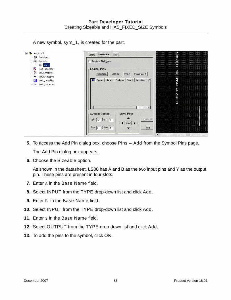
Part Developer TutorialCreating Sizeable and HAS_FIXED_SIZE Symbols
A new symbol, sym_1, is created for the part.
5. To access the Add Pin dialog box, choose Pins – Add from the Symbol Pins page.
The Add Pin dialog box appears.
6. Choose the Sizeable option.
As shown in the datasheet, LS00 has A and B as the two input pins and Y as the outputpin. These pins are present in four slots.
7. Enter A in the Base Name field.
8. Select INPUT from the TYPE drop-down list and click Add.
9. Enter B in the Base Name field.
10. Select INPUT from the TYPE drop-down list and click Add.
11. Enter Y in the Base Name field.
12. Select OUTPUT from the TYPE drop-down list and click Add.
13. To add the pins to the symbol, click OK.
December 2007 86 Product Version 16.01

Part Developer TutorialCreating Sizeable and HAS_FIXED_SIZE Symbols
The pins get added to the symbol with the SIZE property.
Next, you will create a sizeable symbol.
Creating a Sizeable Symbol
1. Right-click on sym_1 and choose Generate Package.
The package is created for the LS00 part.
Since the pins are spread in four slots, you will need to create four slots.
2. To create the four slots, click Functions/Slots.
The Edit Functions dialog box appears.
3. To create 4 slots, click Add and specify 3 in the Specify the number of slots dialog box.
4. Click OK.
5. Click OK to close the Edit Functions dialog box.
December 2007 87 Product Version 16.01

Part Developer TutorialCreating Sizeable and HAS_FIXED_SIZE Symbols
The four slots appear in the Package Editor.
6. Since pin A is mapped to the physical pins1, 4, 9, and 12, enter 1, 4, 9, and 12 under S1,S2, S3, and S4, respectively.
7. Similarly, map the pins B and Y.
December 2007 88 Product Version 16.01

Part Developer TutorialCreating Sizeable and HAS_FIXED_SIZE Symbols
After entering the pins, the Package Pin page should appear as:
Next, you will create a HAS_FIXED_SIZE symbol
Creating a HAS_FIXED_SIZE Symbol
1. Right-click on the sym_1 entry under Symbols in the cell tree and choose Copy.
2. Right-click on the Symbols entry in the cell tree and choose Paste.
December 2007 89 Product Version 16.01

Part Developer TutorialCreating Sizeable and HAS_FIXED_SIZE Symbols
This creates a new symbol, sym_2, which is a copy of sym_1.
3. Click on sym_2.
sym_2 gets loaded in the Symbol Editor.
4. Click Set Size.
The Specify The Symbol Size dialog box appears.
December 2007 90 Product Version 16.01

Part Developer TutorialCreating Sizeable and HAS_FIXED_SIZE Symbols
5. Enter the value of the size property in the New Size field. The value will depend on thenumber of slots in which the pin is present. In this case, Size will be replaced by 4because the pin is present in 4 slots.
6. Save the part. The HAS_FIXED_SIZE property will be automatically added to thesymbol.css file of sym_2.
Note: The HAS_FIXED_SIZE property is not visible from within Symbol Editor.
Caution
Do not change the pin_name <0> pin for HAS_FIXED_SIZE symbols. Thismay lead to the deletion of all the bits of the pin. For example, renamingA<0> may lead to deletion of all the bits of pin A.
Summary
In this chapter, you learned how to create sizeable and HAS_FIXED_SIZE symbols.
December 2007 91 Product Version 16.01

Part Developer TutorialModifying Packages
10Modifying Packages
Objective
To become familiar with the steps involved in modifying packages.
In this chapter, you will learn to:
■ Add pins to a package
■ Add properties to a package
■ Delete pins from a package
■ Delete pins from all packages and symbols
■ Modify pin types
■ Move global pins to logical pins
■ Move logical pins to global pins
■ Modify the footprint information
■ Add Package Pin properties
■ Specify pin swappability
Overview
Often, you need to modify a package to meet changed requirements. Using Part Developer,part modifications can be done quickly and effectively. This chapter covers some of thecommon part-modification tasks. You will use the library part mypart in the my_lib libraryto perform the part-modification tasks.
The part has two packages, MYPART and MYPART_1, and two symbols, sym_1 and sym_2.The symbol sym_1 is associated with the package MYPART and sym_2 with the packageMYPART_1.
December 2007 92 Product Version 16.01

Part Developer TutorialModifying Packages
Adding Pins to a Package
Add an input pin, my_pin, to the MYPART package.
1. Choose File – Open – Cell.
The Open Cell dialog box appears.
2. Select the my_lib library.
3. Select the cell mypart and click OK.
The part mypart loads in the Cell Editor.
4. To select the MYPART package, click the MYPART entry under the Packages entry inthe cell tree.
MYPART gets loaded in the Package Editor.
5. Select the last row in the Logical Pins grid.
6. Press Ctrl + I.
A blank row appears in the Logical Pins grid.
7. Enter my_pin in the Name column and select INPUT from the Type drop-down list.
8. Enter the physical pin number 15 under the column S1.
9. Save the part.
December 2007 93 Product Version 16.01

Part Developer TutorialModifying Packages
Important
The symbol sym_1 is associated with the package MYPART. However, when a pin isadded to the package, the symbol will no longer be packageable into the packageas the pin list will differ. If you select the Keep Symbols Associated check box,Part Developer automatically updates the symbol pin list whenever the package pinlist is modified.
10. To ensure that my_pin has been added to the symbol as well, select the symbol sym_1.
The symbol gets loaded in the Symbol Viewer. Note that the pin appears in the top-leftcorner of the symbol outline.
Adding Properties to a Package
Add the property library_modified_date with the value ? to the MYPART package.
1. Select the MYPART package.
2. Click on the General tab.
December 2007 94 Product Version 16.01

Part Developer TutorialModifying Packages
The General page appears.
3. Select the BODY_NAME property and press Ctrl + I.
A blank row gets created in the Additional Properties grid.
4. Enter LIBRARY_MODIFIED_DATE in the Name column and ? in the Value column.
5. Save the part.
Deleting Pins from a Package
Delete the pin my_pin from the MYPART package.
1. Select the MYPART package.
2. Right-click on the row in the Logical Pins grid that contains the pin MY_PIN and selectDelete Selected Rows.
The pin is deleted from the package.
Important
Since the Keep Symbols Associated option is selected, the pin will beautomatically deleted from sym_1 as well.
3. Save the part.
December 2007 95 Product Version 16.01
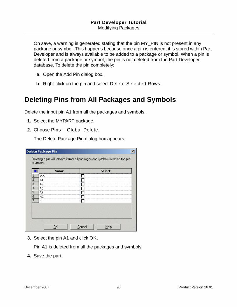
Part Developer TutorialModifying Packages
On save, a warning is generated stating that the pin MY_PIN is not present in anypackage or symbol. This happens because once a pin is entered, it is stored within PartDeveloper and is always available to be added to a package or symbol. When a pin isdeleted from a package or symbol, the pin is not deleted from the Part Developerdatabase. To delete the pin completely:
a. Open the Add Pin dialog box.
b. Right-click on the pin and select Delete Selected Rows.
Deleting Pins from All Packages and Symbols
Delete the input pin A1 from all the packages and symbols.
1. Select the MYPART package.
2. Choose Pins – Global Delete.
The Delete Package Pin dialog box appears.
3. Select the pin A1 and click OK.
Pin A1 is deleted from all the packages and symbols.
4. Save the part.
December 2007 96 Product Version 16.01

Part Developer TutorialModifying Packages
Important
There is no undo action available for pin deletions done using the Delete PackagePin option. Pins deleted using the Delete Package Pin option is deleted from allpackages and symbols.
Modifying Pin Types
Modify the input pins in the MYPART package to BIDIR pins.
1. Select the package MYPART.
2. Select the input pins A2, A3, and A4 in the Logical Pins grid.
3. Right-click on the selection and choose Modify Values from the pop-up menu.
The Modify Values dialog box appears.
4. Select BIDIR from the Type drop-down list.
5. Click OK.
December 2007 97 Product Version 16.01
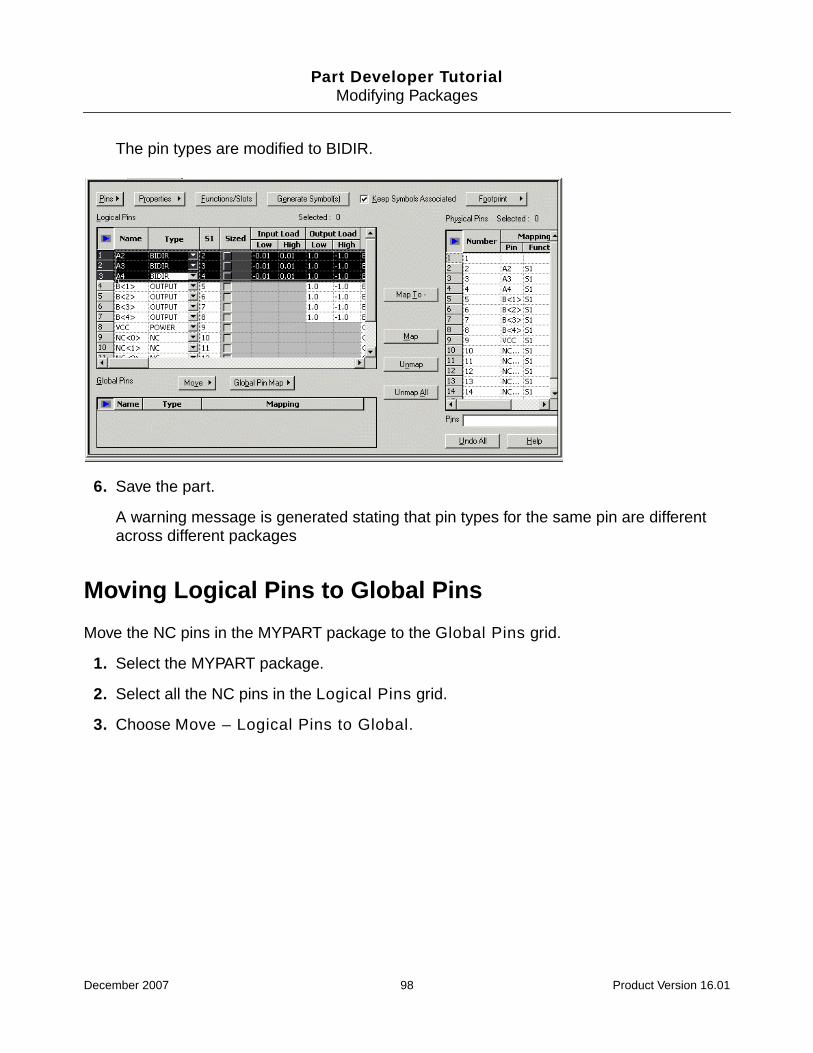
Part Developer TutorialModifying Packages
The pin types are modified to BIDIR.
6. Save the part.
A warning message is generated stating that pin types for the same pin are differentacross different packages
Moving Logical Pins to Global Pins
Move the NC pins in the MYPART package to the Global Pins grid.
1. Select the MYPART package.
2. Select all the NC pins in the Logical Pins grid.
3. Choose Move – Logical Pins to Global.
December 2007 98 Product Version 16.01
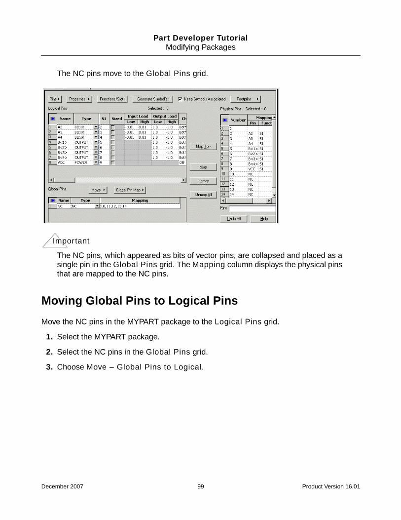
Part Developer TutorialModifying Packages
The NC pins move to the Global Pins grid.
Important
The NC pins, which appeared as bits of vector pins, are collapsed and placed as asingle pin in the Global Pins grid. The Mapping column displays the physical pinsthat are mapped to the NC pins.
Moving Global Pins to Logical Pins
Move the NC pins in the MYPART package to the Logical Pins grid.
1. Select the MYPART package.
2. Select the NC pins in the Global Pins grid.
3. Choose Move – Global Pins to Logical.
December 2007 99 Product Version 16.01

Part Developer TutorialModifying Packages
The NC pins move to the Logical Pins grid.
Important
The NC pins, which appeared as a single pin in the Global Pins grid, appear as bitsof a vector pin in the Logical Pins grid.
Adding Package Pin Properties
Add the package pin property my_pin_property with value val 1 to the pins A2 and A3 ofthe MYPART package.
1. Select the package MYPART.
2. Choose Properties – Add.
December 2007 100 Product Version 16.01
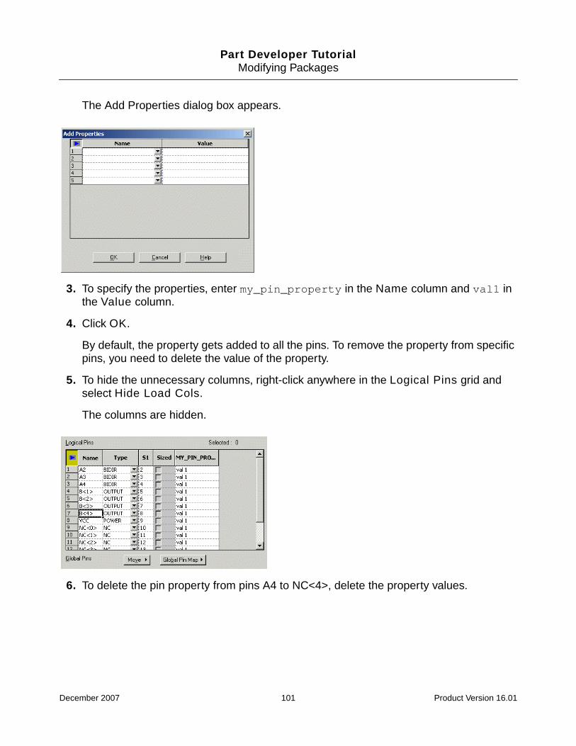
Part Developer TutorialModifying Packages
The Add Properties dialog box appears.
3. To specify the properties, enter my_pin_property in the Name column and val1 inthe Value column.
4. Click OK.
By default, the property gets added to all the pins. To remove the property from specificpins, you need to delete the value of the property.
5. To hide the unnecessary columns, right-click anywhere in the Logical Pins grid andselect Hide Load Cols.
The columns are hidden.
6. To delete the pin property from pins A4 to NC<4>, delete the property values.
December 2007 101 Product Version 16.01

Part Developer TutorialModifying Packages
After the property values are deleted, the Logical Pins grid should appear as follows:
Specifying Pin Swappability
Pin swappability is determined by the PIN_GROUP pin property. The pins that have the samevalues for this property are considered swappable.
Make the pins A2 and A4 of the MYPART package swappable.
1. Select the MYPART package.
2. Choose Properties – Add.
The Add Properties dialog box appears.
3. Select PIN_GROUP from the Name drop-down list.
4. Click OK.
By default, the property gets added to all the pins.
December 2007 102 Product Version 16.01

Part Developer TutorialModifying Packages
5. To hide the unnecessary columns, right-click anywhere in Logical Pins grid and selectHide Load Cols.
The columns are hidden.
6. To make pins A2 and A4 swappable, assign the value 1 for the PIN_GROUP property forpins A2 and A4.
The Logical Pins grid should appear as follows:
7. Save the part.
Summary
In this chapter, you learned how to modify packages.
December 2007 103 Product Version 16.01
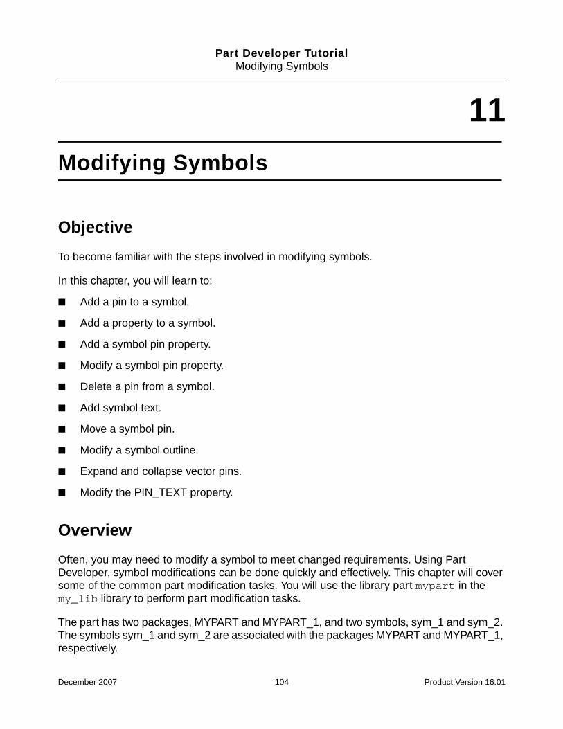
Part Developer TutorialModifying Symbols
11Modifying Symbols
Objective
To become familiar with the steps involved in modifying symbols.
In this chapter, you will learn to:
■ Add a pin to a symbol.
■ Add a property to a symbol.
■ Add a symbol pin property.
■ Modify a symbol pin property.
■ Delete a pin from a symbol.
■ Add symbol text.
■ Move a symbol pin.
■ Modify a symbol outline.
■ Expand and collapse vector pins.
■ Modify the PIN_TEXT property.
Overview
Often, you may need to modify a symbol to meet changed requirements. Using PartDeveloper, symbol modifications can be done quickly and effectively. This chapter will coversome of the common part modification tasks. You will use the library part mypart in themy_lib library to perform part modification tasks.
The part has two packages, MYPART and MYPART_1, and two symbols, sym_1 and sym_2.The symbols sym_1 and sym_2 are associated with the packages MYPART and MYPART_1,respectively.
December 2007 104 Product Version 16.01

Part Developer TutorialModifying Symbols
Adding Pins to a Symbol
Add an input pin A1 to sym_1.
1. Select the symbol sym_1 in the cell tree.
The symbol is loaded in the Symbol Editor.
2. Choose Pins – Add.
The Add Pin dialog box appears.
3. Ensure that the Scalar option is selected and enter A1 in the Prefix field.
4. Select INPUT from the Type drop-down list.
5. Click Add.
The input pin A1 is added to the pin grid.
6. Click OK.
The input pin A1 gets added to the symbol.
December 2007 105 Product Version 16.01

Part Developer TutorialModifying Symbols
Caution
Changes to the symbol pin list will result in breaking symbol-packageassociations. You will need to update the package pin list to ensure thatthe symbol is usable in the flow. You can use Interface Comparator tosynchronize the pin lists of packages and symbols. See InterfaceComparator on page 148 for more details on interface comparison.
Important
The Preserve Pin Position option determines whether the pin positions and theirassociated properties and pin text will be preserved when the symbol outline ismodified. If the option is not selected, the pin positions, their properties, and the pintext are adjusted dynamically when the symbol outline changes. Otherwise, the pinpositions, their properties and pin text do not change with the change in the symboloutline.
Whenever a new symbol is created, this option is deselected by default. This allows PartDeveloper to dynamically shift the pins on the symbol outline as and when new pins areadded.
Note: Part Developer will extend the symbol outline when new pins are added. However,no symbol-outline contraction is done when symbol pins are deleted. You need tomanually resize the symbol outline. When an existing symbol is loaded, this option isselected by default. This is done to ensure that graphics associated with a symbol pinare not destroyed by the automatic movement of pins. This also ensures that in the caseof horizontal or vertical extension of the symbol outline due to the addition of pins, thepins on top/bottom or left/right of the symbol remain bounded to the symbol outline.
Adding Properties to a Symbol
Add the property my_symbol_prop with value sym_val in sym_1.
1. Select sym_1 in the cell tree.
The symbol is loaded in the Symbol Editor.
2. Click on the General tab.
3. Right-click on the Properties grid and select Insert Row After.
A blank row is added to the Properties grid.
4. Enter my_symbol_prop in the Name column and sym_val in the Value column.
December 2007 106 Product Version 16.01

Part Developer TutorialModifying Symbols
Next, you need to determine the appearance of the property and its value on the symbol.
5. To make both the property and its value visible, select Both from the Visibility drop-down list.
6. To make the property appear in the top-right corner of the symbol, select Top-Right fromthe Location drop-down field.
Similarly, you can specify other values, such as rotation, alignment, and so on. Note thatthe changes you make are immediately visible on the Symbol Editor canvas.
Adding Symbol Pin Properties
Add the symbol pin property PIN_DELAY with values 2 ps and 3 ps to the pins A2 and A3.
1. Select sym_1 in the cell tree.
The symbol is loaded in the Symbol Editor.
2. Select Properties – Add.
December 2007 107 Product Version 16.01

Part Developer TutorialModifying Symbols
The Add Properties dialog box appears.
3. Enter PIN_DELAY in the Name column and click OK.
The PIN_DELAY property is added. By default, the property will get added to only thosepins that have a value. A null value results in the property being omitted from the pins.
4. To add the value of 2 ps to the pin A2, enter 2 ps in the A2 row in the PIN_DELAYcolumn.
5. Similarly, specify 3 ps as the PIN_DELAY property value for the pin A3.
The Logical Pins grid should appear as follows:
December 2007 108 Product Version 16.01

Part Developer TutorialModifying Symbols
Modifying Symbol Pin Properties
Modify the PIN_DELAY symbol pin property to make it visible on the symbol pins.
1. Select sym_1 in the cell tree.
The symbol gets loaded in the Symbol Editor.
2. Select the PIN_DELAY column in the Logical Pins grid.
3. Select Properties – Attributes.
The Symbol Pin Property Attributes dialog box appears.
4. For pins A2 and A3, select Both from the Visibility drop-down list box.
Similarly, you can modify the other attributes through this dialog box.
5. Click Close.
December 2007 109 Product Version 16.01

Part Developer TutorialModifying Symbols
The symbol pin properties appear next to the pins A2 and A3.
Deleting Pins from a Symbol
Delete the pin A2 from sym_2.
1. Select sym_2 in the cell tree.
The symbol gets loaded in the Symbol Viewer.
2. Right-click on the pin A2 and select Delete Selected Rows.
The pin gets deleted from sym_2.
Adding Symbol Text
Add the text Aoyon to sym_1.
1. Select sym_1 in the cell tree.
The symbol gets loaded in the Symbol Viewer.
2. Click on the General tab.
3. Right-click on the Text grid and select Insert Row After.
A blank row is inserted in the Text grid.
December 2007 110 Product Version 16.01

Part Developer TutorialModifying Symbols
4. Enter Aoyon in the text column.
5. To make the text appear in the top-left location of the symbol, select Top-Left from theLocation drop-down box.
The symbol text appears in the top-left corner of the symbol.
Moving Symbol Pins
Move the pins A2 and A3 by 1 grid to the left and pin A4 by 4 grids to the right.
1. Select sym_1 in the cell tree.
The symbol gets loaded in the Symbol Viewer.
2. Select the pins A2 and A3.
December 2007 111 Product Version 16.01

Part Developer TutorialModifying Symbols
Note that the Symbol Viewer shows the selected pins.
3. To move the pins by one grid to the left, click the left arrow button in the Move Pins grid.
The selected pins move to the left by one grid.
4. Next, select pin A4.
5. To move pins by more than one grid at a time, click Move.
The Move Pin dialog box appears.
6. Select Right from the Direction drop-down list box.
7. Enter 4 in the Grid units to move field.
8. Click OK.
The pin A4 moves to the right by 4 grid units.
December 2007 112 Product Version 16.01

Part Developer TutorialModifying Symbols
Modifying Symbol Outline
Increase the left and right outline of sym_2 by 5 grids.
1. Select sym_2 in the cell tree.
The symbol loads in the Symbol Editor.
2. Enter the value -10 in the Left field in the Symbol Outline group box.
3. Enter the value 10 in the Right field in the Symbol Outline group box.
The symbol outline changes as specified. Note that the symbol pin positions are notchanging automatically with the change in the symbol outline. This is because the
December 2007 113 Product Version 16.01

Part Developer TutorialModifying Symbols
Preserve Pin Position option is selected. If you want to move the pin automatically withthe symbol outline, deselect the Preserve Pin Position option.
Expanding and Collapsing Vector Pins
Collapse the bits of the vector pin B.
1. Select all the bits of the vector pin B.
2. Right-click on the selection and select Collapse.
Part Developer gives an error message saying that bit-specific properties might get loston collapsing.
3. Click Yes.
December 2007 114 Product Version 16.01
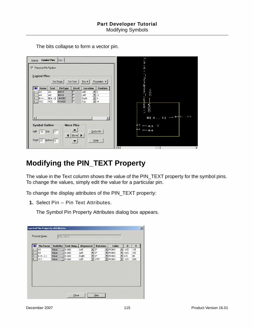
Part Developer TutorialModifying Symbols
The bits collapse to form a vector pin.
Modifying the PIN_TEXT Property
The value in the Text column shows the value of the PIN_TEXT property for the symbol pins.To change the values, simply edit the value for a particular pin.
To change the display attributes of the PIN_TEXT property:
1. Select Pin – Pin Text Attributes.
The Symbol Pin Property Attributes dialog box appears.
December 2007 115 Product Version 16.01

Part Developer TutorialModifying Symbols
2. Change the display attributes as required and click Close.
Summary
In this chapter, you learned how to modify symbols.
December 2007 116 Product Version 16.01

Part Developer TutorialModifying Symbols
December 2007 117 Product Version 16.01

Part Developer Tutorial
12Editing Symbol Graphics
Objective
To become familiar with the steps in editing symbol graphics by using the Symbol Editor.
In this chapter, you will learn to:
■ Draw graphical objects to add to a symbol
■ Create a group of symbol objects
■ Rotate an object
■ Align objects
■ Add a bitmap to a symbol
■ Perform move and stretch operations on symbol objects
■ Perform zoom and pan operations on a symbol
Overview
In Part Developer, you can modify a symbol in two ways, by changing the values of variousfields in the Symbol Pins panel or by modifying the symbol text and graphics on the SymbolEditor canvas. While some symbol modification tasks, such as changing the location of a pinfrom left to right, can be done using either the Symbol Pins panel or the Symbol Editor, someother tasks, such as adding graphics to indicate the functionality of the symbol, can be doneonly using the Symbol Editor. This chapter covers various Symbol Editor features, which youcan use to edit symbol graphics. You will use the library part sample_part in the my_liblibrary.
The part sample_part has six symbols.
December 2007 118 Product Version 16.01
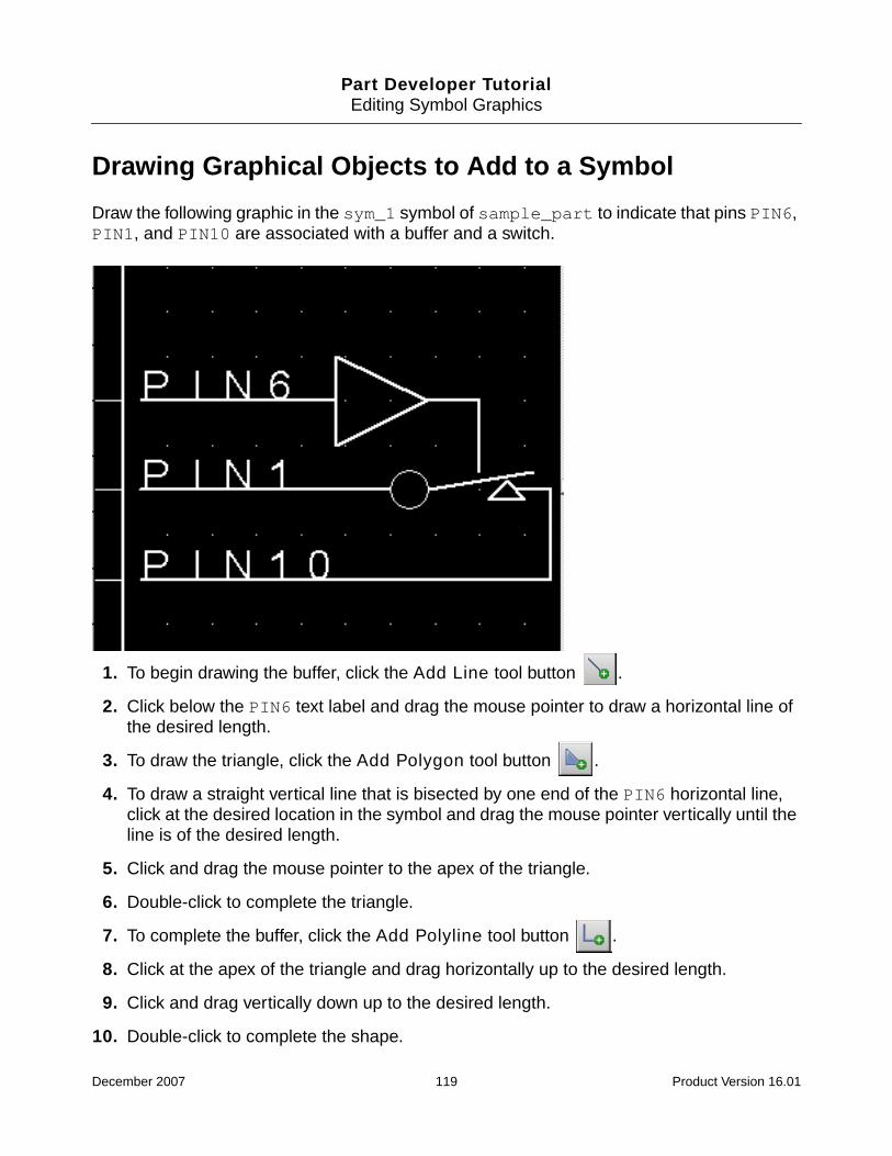
Part Developer TutorialEditing Symbol Graphics
Drawing Graphical Objects to Add to a Symbol
Draw the following graphic in the sym_1 symbol of sample_part to indicate that pins PIN6,PIN1, and PIN10 are associated with a buffer and a switch.
1. To begin drawing the buffer, click the Add Line tool button .
2. Click below the PIN6 text label and drag the mouse pointer to draw a horizontal line ofthe desired length.
3. To draw the triangle, click the Add Polygon tool button .
4. To draw a straight vertical line that is bisected by one end of the PIN6 horizontal line,click at the desired location in the symbol and drag the mouse pointer vertically until theline is of the desired length.
5. Click and drag the mouse pointer to the apex of the triangle.
6. Double-click to complete the triangle.
7. To complete the buffer, click the Add Polyline tool button .
8. Click at the apex of the triangle and drag horizontally up to the desired length.
9. Click and drag vertically down up to the desired length.
10. Double-click to complete the shape.
December 2007 119 Product Version 16.01

Part Developer TutorialEditing Symbol Graphics
11. To draw the switch, first draw a horizontal line of the desired length below the PIN1 textlabel.
12. To draw a circle at the end of the horizontal line, click the Add Circle tool button .
13. Click on the desired location and drag the mouse pointer to draw the diameter of thecircle.
14. Release the mouse pointer.
The circle is drawn.
15. Using the Add Line tool button, draw a slanted line from the circle.
16. Using the Add Polygon tool button, draw a small triangle, the apex of which touches theslanted line.
17. Draw a horizontal line below the PIN10 text label and drag it vertically up and thenhorizontally left to connect to the small triangle.
The graphic is complete.
Tip
When drawing objects, you can either copy/paste or use the Make componentsthe same width and Make components the same height tool buttons to createobjects of identical dimensions.
Tip
To draw objects that should not be snapped to fit into the grid, make sure the Snapto Grid option is not selected. You can access this option from the Canvas menuitem on the Graphic Editor menu or from the toolbar using the Snap to Grid toolbutton .
Creating a Group of Symbol Objects
In sym_1, create a group of the two pins PIN+ and PIN- so that the pins can be movedtogether.
1. To select the PIN+ pin along with its name and text label, click the pin when the mousepointer changes to the move icon. You will notice that the same pin gets selected in theSymbol Pins panel.
2. Keeping the Ctrl key pressed, click the PIN- pin.
December 2007 120 Product Version 16.01

Part Developer TutorialEditing Symbol Graphics
Both the pins are selected. Notice that each selected pin is displayed in a separate box.
3. Right-click on the selection.
4. Click the Group option.
Notice that all the selected objects are now displayed in a single box. This indicates thatthe group is created. You can now do any operation on the grouped object.
Tip
You can also select pins from the Symbol Pins panel by clicking the row number inthe first column of the Logical Pins grid. This method of selection cannot be used ifyou want to select symbol objects other than pins.
Rotating an Object
In the sym_2 symbol, rotate the first triangle to make it inverted.
1. Create a group of the three lines that constitute the first triangle.
2. Click the Rotate 90 degrees counter clockwise tool button two times.
December 2007 121 Product Version 16.01

Part Developer TutorialEditing Symbol Graphics
The triangle is inverted.
Aligning Objects
In the sym_3 symbol, left-align the first horizontal line with the second horizontal line.
1. Select the first horizontal line.
2. Keeping the Ctrl key pressed, select the second horizontal line.
3. Click the Align Left tool button .
December 2007 122 Product Version 16.01

Part Developer TutorialEditing Symbol Graphics
The line selected first is left-aligned with the line selected next. In the case of more thantwo objects, all objects are aligned with the last selected object.
Tip
To make a set of circles concentric, select all the circles and then click the AlignMiddle tool button and the Align Center tool button.
Adding a Bitmap to a Symbol
Add the bitmap logo.bmp to the sym_4 symbol.
1. Click the Add Image tool button .
December 2007 123 Product Version 16.01

Part Developer TutorialEditing Symbol Graphics
The Open dialog box displays.
2. The path of the logo.bmp file is\library_project\my_lib\sample_part\images. Browse the my_lib folder toselect the bitmap logo.bmp and click the Open button.
Notice that the mouse pointer changes to indicate that an image is being added.
3. To add the image, click at the desired location on the canvas.
The image is added to the symbol. You can stretch the image to increase its size.
Important
Make sure that the image to be added is stored in a .bmp file or a .jpg file.
Performing Move and Stretch Operations on SymbolObjects
Move the group of PIN+ and PIN- pins a few grid points down in the sym_5 symbol. Increasethe symbol size by dragging the symbol outline.
1. Create a group of PIN+ and PIN- pins.
December 2007 124 Product Version 16.01

Part Developer TutorialEditing Symbol Graphics
2. Place the mouse pointer on either pin and drag the group to the desired location in thesymbol.
The group is moved to the new location.
3. To increase the length of the symbol, move the horizontal line at the base of the symboldown to the desired location.
Notice that a yellow dotted line indicating the existing symbol outline is displayed at theoriginal location.
4. Click the dotted line to display stretch handles and drag the middle handle until theoutline merges with the horizontal line that you had moved to the new location.
The symbol size is increased according to your specification.
Tip
To move an object by a fraction of a grid in any direction, you can use Nudge Up,Nudge Down, Nudge Left, or Nudge Right tool buttons.
Tip
To move pins from one side of the symbol to another, use the Symbol Pins panelinstead of the Symbol Editor. Part Developer automatically adjusts the direction of apin when the Location column value for the pin is changed in the Symbol Pinspanel.
Performing Zoom and Pan Operations on a Symbol
Zoom in on the switch graphics associated with the PIN1 pin in sym_6. After the object hasbeen magnified according to your specification, pan the Symbol Editor canvas to display onlythe PIN+ and PIN- pins.
1. Click the Zoom By Points tool button .
Notice that the mouse pointer changes to a magnifying glass.
2. Using the mouse, drag and select an area that encloses the switch associated with thePIN1 pin.
December 2007 125 Product Version 16.01

Part Developer TutorialEditing Symbol Graphics
The switch is magnified.
Note: If you want to edit the graphics, first press Esc to exit the zoom mode.
3. To pan the canvas so that the PIN+ and PIN- pins can be viewed, click the Pan toolbutton .
The mouse pointer changes to a hand.
4. Click and release the mouse button only after the PIN+ and PIN- pins are displayed atthe desired location on the Symbol Editor canvas.
Tip
If you are using a three-button mouse, you can pan using the middle mouse button.
December 2007 126 Product Version 16.01

Part Developer TutorialEditing Symbol Graphics
Summary
In this chapter, you learned how to edit symbol graphics.
December 2007 127 Product Version 16.01

Part Developer TutorialImporting and Exporting
13Importing and Exporting
Objective
To become familiar with commonly used import and export procedures.
In this chapter, you will learn to:
■ Import pin information from a CSV file to create a part.
■ Import changed pin information (Import ECO) from a CSV file to update an existing part.
■ Export part information to save in CSV format.
■ Import pin information from an FPGA component to create a part.
■ Import pin information from a die file to create a part.
■ Export part information to create a Capture part.
■ Export part information to save in ViewLogic format.
Overview
Support for a wide variety of file import and export in Part Developer makes Part Developera powerful library-development tool. The Import and Export wizard of Part Developer not onlyspeeds up logical-part creation but also eliminates the errors that are often introducedinadvertently when information is copied from one tool to another.
This chapter covers some of the import and export procedures that are commonly used bylibrarians.
The data files that you can use to try the import procedures covered in this chapter are storedin a directory called import_files at<your_inst_dir>\doc\pdv_tut\tutorial_data.
December 2007 128 Product Version 16.01

Part Developer TutorialImporting and Exporting
CSV Import and Export
CSV format enables you to maintain data in tool-independent format. If you need to supportdesign teams that use multiple schematic editors with a layout tool, such as Allegro PCBEditor, you can single-source part data with CSV import and export support.
In this tutorial, you will:
■ Import the pentium4_3Ghz.csv file to create a part named p4_3ghz.
■ Update the p4_3ghz part by importing changed pin information from the CSV file thatwas used to create the part.
■ Export the part details of the p4_3ghz part to a CSV file, p4_3Ghz.csv.
Importing a CSV File
Import the pentium4_3Ghz.csv file to create a part named p4_3ghz.
Import File Description
The pentium4_3Ghz.csv file contains information about logical and physical pins andsymbols. When creating a part from this information, Part Developer maps the logical andphysical pins and generates symbols for the part.
Task Overview
When creating the p4_3ghz part from the pentium4_3Ghz.csv file, do the following:
■ Convert the duplicate BIDIR pins to the bits of a vector pin.
■ Move the duplicate POWER pins to the global pin list.
■ Change the type of the UNSPEC pins to INPUT.
Steps
The steps are as follows:
1. Open the tutorial_project.cpm project from the library_project folder intutorial_data.
December 2007 129 Product Version 16.01

Part Developer TutorialImporting and Exporting
2. Choose File – Import and Export.
The Import and Export wizard appears.
3. Choose the Import Comma Separated Value (.csv) file option and click Next.
The Select Source page appears.
4. Browse to select the input CSV file pentium4_3Ghz.csv from the import_files folderand click Open.
5. Click Next.
The Select Destination page appears.
The name of the part to be created is seeded automatically from the CSV filename.
6. Change the part name to p4_3ghz by deleting the necessary characters in the displayedpart name.
7. Select the library my_lib and click Next.
The Preview of Import Data page appears.
8. Change the type of pin P100 from UNSPEC to INPUT by choosing the INPUT option fromthe Type drop-down list.
9. Click Finish to complete the part creation process.
Duplicate Pin Resolver Dialog displays the duplicate pins in the CSV file and providesoptions to resolve the duplicate pins. You can convert the duplicate pins into the bits of avector pin, define them as individual scalar pins, or move them to the global pin list.
10. To convert the six BPM pins into a vector pin of six bits, retain the Vector option in theConvert column.
11. To move the duplicate POWER pins VCC_1 and VSS_1 to the global pin list, select theGlobal option from the Convert list for each pin.
12. Click OK.
The Cell Editor appears with the part information.
13. Save the imported part and close the Cell Editor.
Importing a CSV File to Update a Part
Import pin information from a CSV file, pentium4_3Ghz_eco.csv, in the ECO process toupdate the p4_3ghz part.
December 2007 130 Product Version 16.01

Part Developer TutorialImporting and Exporting
Task Overview
When updating the p4_3ghz part, do the following:
■ Make sure that all symbol graphic modifications that have been done during ECO areretained.
Steps
1. Choose File – Import and Export.
The Import and Export wizard appears.
2. Choose the Import ECO - Comma Separated Value (.csv) file option and click Next.
The Select Source for ECO page appears.
3. Browse to select the CSV file pentium4_3Ghz_eco.csv and click Open.
4. Click Next.
The Select Destination for ECO page appears.
5. Select my_lib as the library and p4_3ghz as the destination cell and click Next.
The Preview of Import Data page appears.
6. Click Next.
Duplicate Pin Resolver Dialog displays the duplicate pins in the CSV file.
7. Resolve the duplicate pins and click OK.
8. Click Next.
The ECO Messages page appears.
9. To retain all symbol graphic modifications that have been done during ECO, make surethat the Graphic modifications check box in the Ignore section is not selected.
10. Click Finish.
The Cell Editor appears with the part information.
11. Save the updated part and close the Cell Editor.
December 2007 131 Product Version 16.01

Part Developer TutorialImporting and Exporting
Exporting to a CSV File
Export the details of a part named p4_3ghz to a CSV file, p4_3Ghz.csv.
Steps
The steps are as follows:
1. Choose File – Import and Export.
The Import and Export wizard appears.
2. Choose the Export Comma Separated Value (.csv) file option and click Next.
The Select Source page appears.
3. Select my_lib as the source library and p4_3ghz as the cell to be exported and clickNext.
The Select Package page appears.
4. Select P4_3GHZ as the package and click Next.
5. Specify import_files as the directory in which to save the CSV file and click Finish.
The p4_3ghz part is exported.
Note: The CSV filename is derived from the package name of the part.
Importing an FPGA Component
Import the Xilinx place-and-route file xilinx_7x.pad to create a library part namedxilinx_7x.
Task Overview
■ Make sure that you create a new schematic symbol for the imported FPGA.
■ Specify the default values for the following properties:
❑ DESCRIPTION
❑ JEDEC_TYPE
December 2007 132 Product Version 16.01
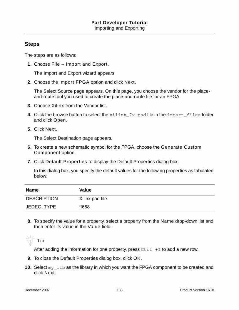
Part Developer TutorialImporting and Exporting
Steps
The steps are as follows:
1. Choose File – Import and Export.
The Import and Export wizard appears.
2. Choose the Import FPGA option and click Next.
The Select Source page appears. On this page, you choose the vendor for the place-and-route tool you used to create the place-and-route file for an FPGA.
3. Choose Xilinx from the Vendor list.
4. Click the browse button to select the xilinx_7x.pad file in the import_files folderand click Open.
5. Click Next.
The Select Destination page appears.
6. To create a new schematic symbol for the FPGA, choose the Generate CustomComponent option.
7. Click Default Properties to display the Default Properties dialog box.
In this dialog box, you specify the default values for the following properties as tabulatedbelow:
8. To specify the value for a property, select a property from the Name drop-down list andthen enter its value in the Value field.
Tip
After adding the information for one property, press Ctrl +I to add a new row.
9. To close the Default Properties dialog box, click OK.
10. Select my_lib as the library in which you want the FPGA component to be created andclick Next.
Name Value
DESCRIPTION Xilinx pad file
JEDEC_TYPE ff668
December 2007 133 Product Version 16.01

Part Developer TutorialImporting and Exporting
The Preview of Import Data page appears.
11. Click Finish.
The Cell Editor appears with the part information.
12. Save the imported part and close the Cell Editor.
You can now use the Component Browser to add the FPGA component or the blockinstantiating the FPGA component in your design.
Importing a Die File
Import the die file transceiver.txt from the import_files folder to create a librarypart named transceiver.
Task Overview
When creating the transceiver part from the transceiver.txt die file, do thefollowing:
■ Change the type of the UNSPEC logical pins to INPUT.
Steps
The steps are as follows:
1. Choose File – Import and Export.
The Import and Export wizard appears.
2. Choose the Import Die Text option and click Next.
The Select Source page appears.
3. Click the browse button to select the die file transceiver.txt and click Open.
4. Click Next.
The Select Destination page appears.
The name of the part to be created is seeded automatically from the name of the die file.
5. Select my_lib as the destination library and click Next.
The Preview of Derived Data page appears.
December 2007 134 Product Version 16.01

Part Developer TutorialImporting and Exporting
All the pins are of the UNSPEC type.
6. To change the type of all the pins to INPUT, select all the values in the Type column.
7. Right-click and choose the Modify Values option from the pop-up menu.
8. Click the drop-down button in the Value cell, choose INPUT from the displayed list, andclick OK.
The types of all the pins are changed to INPUT.
9. Click Finish to complete the part creation process.
Duplicate Pin Resolver Dialog displays the duplicate pins in the die file.
10. To convert the duplicate pins to vector pins, retain the Vector option in the Convertcolumn and click OK.
The Cell Editor appears with the part information.
11. Save the imported part and close the Cell Editor.
Exporting to a Capture Part
Export the details of a part named p4_3ghz_sym to create a Capture part.
Task Overview
Make sure that the symbol port names are used to represent the pins in Capture.
Steps
The steps are as follows:
1. Choose File – Import and Export.
The Import and Export wizard appears.
2. Choose the Export Capture Part (Windows Only) option and click Next.
The Select Source page appears.
3. Select my_lib as the source library and p4_3ghz_sym as the part to be exportedand click Next.
The Select Package and Symbol(s) page appears.
December 2007 135 Product Version 16.01

Part Developer TutorialImporting and Exporting
4. Select the P4_3GHZ_SYM package.
5. To use the symbol port names as pin names in Capture, select the Use Pin Name towrite Capture Port name check box.
6. Click Next.
7. Browse to the import_files folder, specify export_p4_3ghz as the name of the Capturelibrary in which the part is to be created, and click Open.
8. Click Finish.
The part details have been exported to a file called EXPORT_P4_3GHZ.OLB. You canlaunch Capture and view the part.
Exporting to a ViewLogic Part
Export the details of a part named p4_3ghz_sym to save in ViewLogic format.
Steps
The steps are as follows:
1. Choose File – Import and Export.
The Import and Export wizard appears.
2. Choose the Export ViewLogic(VL) Part option and click Next.
The Select Source page appears.
3. Select my_lib as the source library and p4_3ghz_sym as the cell to be exportedand click Next.
The Select Associated Package(s) or Unassociated Symbol(s) page appears.
4. Select the P4_3GHZ_SYM package, specify the type of the ViewLogic part as Non-Hetero, and click Next.
The Select Destination page appears.
5. Specify the destination directory and click Finish.
The part is exported. If you have ViewLogic installed, you can open the newly createdpart.
December 2007 136 Product Version 16.01

Part Developer TutorialImporting and Exporting
Summary
In this chapter, you learned how to use Part Developer to import pin information from variousformats for creating Design HDL parts and export pin information from Design HDL parts tovarious formats.
December 2007 137 Product Version 16.01

Part Developer TutorialPart Logging and Versioning
14Part Logging and Versioning
Overview
Part Logging and Versioning is the feature using which you can store and view the followinginformation about a part:
■ A log of all actions done on a part, such as symbol creation and pin modifications.
■ Major and minor revision numbers of all the views.
By default, whenever you start part logging, Part Developer assign the major revision numberfor all views and the cell as 1. The minor revision number is 0. Then, depending upon thetypes of changes you make to the part or views, the major or minor number of the part or theviews are updated automatically by Part Developer.
Whenever a major or a minor revision number of a view is incremented, the major or minorrevision number of the cell is also incremented. For example, a part and its package andsymbol views have a major revision number 1 and a minor revision number 0. Now, thepackage undergoes a modification, resulting in a major revision number change for thepackage. This will cause the major revision number of the part to be incremented as well. So,the part and the package will have the major revision number as 2. Now, the symbol ismodified, resulting in the major revision number of the symbol to be incremented. This willalso result in the major revision number of the part to be incremented. So, the part will nowhave the major revision number as 3 while the major revision numbers of the package andthe symbol continue to be 2. See Modifications that Result in Major and Minor NumberChanges on page 145 for details.
The part log and version information is stored in the metadata view of the part. The metadataview contains the following files:
❑ master.tag
The master.tag file is the control file that ensures that Part Developer treats thisdirectory as a valid view.
❑ revision.dat
December 2007 138 Product Version 16.01

Part Developer TutorialPart Logging and Versioning
The revision.dat file stores the version information for a part. The informationstored includes the name of the view, the type of the view, major and minor revisionnumbers, the date and time of creation, the name of the creator, the library to whichthe part belongs, and the modification history.
❑ revision.log
The revision.log file logs all the activities that are done on the part. Theinformation stored includes the time of the modification, the name of the modifier,the type of modification, and a detailed description of the type of change.
Both revision.dat and revision.log files are written when the part is saved.
❑ pinlist.txt
The pinlist.txt file stores the list of pins that have been added to the part.
Part Developer will start logging all the changes that you make on the part and alsoautomatically increment the major or minor version of the views and parts as required.
Caution
Do not manually edit the revision.dat and the revision.log files outside ofPart Developer. If these files are manually edited, Part Developer may failto give you the correct version information or logging information for thepart.
Starting Part Logging and Versioning
Task Overview
Load the for_baselining part from the my_lib library and baseline it. Modify the packageby deleting the input pin A1. View the version numbers after the changes are made to the part.
Steps
1. Select File – Open – Cell.
The Open Cell dialog box appears.
2. Select the for_baselining part from the my_lib library and click OK.
December 2007 139 Product Version 16.01

Part Developer TutorialPart Logging and Versioning
The part is loaded in the Cell Editor. Note that by default, the Major revision number isassigned as 1 for the existing views. Also, the Major status appears as Created.
3. Select the BaseLine on Save option.
4. Save the part.
5. To view the change log and revision numbers in Part Developer, close the part and reloadit.
The Revision Editor appears with the major version appearing as Baselined for the celland all its views. Now, whenever any change is made to the cell, the revision number willget updated as required.
Note: The changes are not dynamically reflected in the Revision Editor. You will need to
December 2007 140 Product Version 16.01

Part Developer TutorialPart Logging and Versioning
reload the part to see all the revision history.
Important
The BaseLine on Save option is deselected on reloading the part. You will need toselect the BaseLine on Save option before saving the part to ensure that therevision numbers are updated.
In case a baselined part is saved with the BaseLine on Save option checked, a.baselined file is created in all the views. For example, chips.prt.baselined iscreated in the chips view. Now, if the part is saved with the BaseLine on Save optionchecked, the views are compared against the .baselined files and revision numbersare updated accordingly.
Important
Part logging is possible only for error-free parts.
6. Select the FOR_BASELINING package in the cell tree.
7. Delete the input pin A1.
8. Click on the root of the cell tree.
9. Select BaseLine on Save.
10. Save the part.
December 2007 141 Product Version 16.01

Part Developer TutorialPart Logging and Versioning
11. Close and reload the part.
The major version is updated for the part.
Viewing the Revision Log
1. To view the revision log file, click Change log.
December 2007 142 Product Version 16.01
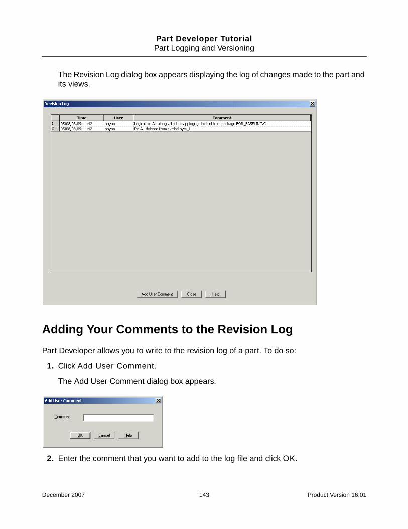
Part Developer TutorialPart Logging and Versioning
The Revision Log dialog box appears displaying the log of changes made to the part andits views.
Adding Your Comments to the Revision Log
Part Developer allows you to write to the revision log of a part. To do so:
1. Click Add User Comment.
The Add User Comment dialog box appears.
2. Enter the comment that you want to add to the log file and click OK.
December 2007 143 Product Version 16.01

Part Developer TutorialPart Logging and Versioning
The comment is written to the revision.log file and appears in the Revision Logdialog box.
Stopping Part Logging and Versioning
➤ To stop part logging and versioning, deselect the BaseLine on Save option.
Restarting Part Logging and Versioning
➤ To start part logging and versioning, select the BaseLine on Save option.
December 2007 144 Product Version 16.01
Part Developer TutorialPart Logging and Versioning
Modifications that Result in Major and Minor NumberChanges
The changes that impact the design flow are considered major changes, leading to anincrement in the major revision number. All other changes are treated as minor changes andresult in incrementing the minor revision number.
Modifications that Result in a Major Number Change for a Part or a View
The following modifications cause a change in the major revision number:
■ Addition, deletion, or renaming of any view
■ Modification of the JEDEC_TYPE property
■ Addition or deletion of pins from packages and symbols
■ Modification of the pin type for an existing pin
■ Renaming of pins in the package and symbols
■ Addition, deletion, or renaming of symbol text
■ Modification of a symbol pin position
■ Addition or deletion of slots from a package
■ Change in the low-assertion character setup for a part, resulting in the change of howthe low-assertion character is stored in the chips and the symbol view
■ Change in the distribution of pins among slots
■ Change in the mapping information of existing pins
■ Global renaming of pins
■ Global deletion of pins
■ Addition or deletion of a model for a wrapper
■ Modification of a model for an existing wrapper
■ Mapping or unmapping of pin to m-port mapping in a mapfile or a wrapper
■ Addition, deletion, or modification of the binding statement for a VHDL wrapper ormapfile
December 2007 145 Product Version 16.01
Part Developer TutorialPart Logging and Versioning
■ Addition or deletion of pin-to-model port mapping for primitives from Verilog/VHDLmapfiles
■ Modification of the default_model property for a primitive in the map view
■ Addition, deletion, or modification of a model for a primitive entry in the mapfile
■ Annotation of parameters or generics onto symbols
■ Deletion of annotated parameters or generics from the symbols
■ Updating pin-mode/port-type of pins during Verilog/VHDL mapfile/wrapper creation
■ Modification of the UPPERCASE property of primitives
Modifications that Result in a Minor Number Change for a Part or a View
■ Addition, deletion, or renaming of an additional package property
■ Addition, deletion, or renaming of a package pin property
■ Addition, deletion, or renaming of a package alias
■ Modification of the electrical class of a package
■ Modification of the reference designator prefix of a package
■ Addition, deletion, or renaming of a symbol property
■ Addition, deletion, or renaming of a symbol pin property
■ Modification of the symbol outline (thickness/width/height)
■ Modification of the color of the symbol outline
■ Change of pin-shape
■ Modification of symbol and symbol pin attributes
■ Addition or deletion of the model alias from the primitive in the mapfile
Summary
In this chapter, you learned how to create and maintain part versions and change logs.
December 2007 146 Product Version 16.01

Part Developer TutorialPart Logging and Versioning
December 2007 147 Product Version 16.01

Part Developer TutorialInterface Comparator
15Interface Comparator
Overview
The Interface Comparator is a mechanism by which you can compare the pin lists of twointerfaces, such as a package and a symbol, identify the differences between them and thenupdate the pin list of one of the objects to match the other, or both with respect to each other.
The following scenario explains the need and usefulness of this feature. Suppose you createa part where you develop the packages and symbols separately. After creating them, yourealize that there are some symbols that are unassociated with any of the packages. Such apart is not usable in the design flow because the symbols must be packageable into one ofthe packages. To make a symbol packageable, you need to update the pin list of the symbolto match the pin list of the package or vice-versa. For large pin-count parts, this task, whendone manually, can be tiresome and error-prone. The Interface Comparator feature enablesyou to automatically identify the differences between the selected symbol and the packageand update the pin list of either the symbol or the package to match the other.
Using Interface Comparator, you can do comparisons between:
■ A function group and a symbol
■ Two function groups of a package
■ Two symbols
After the comparison, you can choose to update the pin list of one of the compared objectswith the pin list of the other or both with respect to each other.
A sample part, lib_part_for_interface_comparison is used to explain this.lib_part_for_interface_comparison has one package with four pins, A, B, C,and D. These four pins are split into two function groups, with pins A and B forming the first
December 2007 148 Product Version 16.01

Part Developer TutorialInterface Comparator
function group, and pins C and D forming the other. The pin list of the package is displayedbelow:
lib_part_for_interface_comparison also has two symbols, sym_1 and sym_2.The symbols are displayed below:
Sym_2 is associated with the second function group. Sym_1 has pins A and B and an extrapin M. This results in sym_1 being not associated with any function group.
The Interface Comparator will be used to synchronize the function group with the symbol. Asa result of this synchronization, the logical pin M will be added to the first function group. PartDeveloper will ensure that the synchronization does not destroy the existing function groupand symbol associations, for example, the association of sym_2 with function group 2.
Running the Interface Comparator
Task Overview
Synchronize the sym_1 symbol of the lib_part_for_interface_comparison partof the my_lib library with the lib_part_for_interface_comparison package.
Steps
1. Load the lib_part_for_interface_comparison part in Part Developer.
Sym_1 Sym_2
December 2007 149 Product Version 16.01
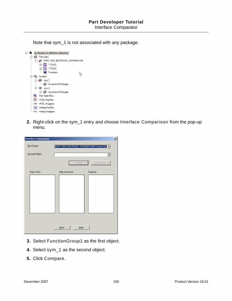
Part Developer TutorialInterface Comparator
Note that sym_1 is not associated with any package.
2. Right-click on the sym_1 entry and choose Interface Comparison from the pop-upmenu.
3. Select FunctionGroup1 as the first object.
4. Select sym_1 as the second object.
5. Click Compare.
December 2007 150 Product Version 16.01

Part Developer TutorialInterface Comparator
Part Developer runs a comparison check on the logical pin lists of the two objects anddisplays the results in the following way:
❑ The pins that are present only in the first object are displayed in the Only in Firstlist box.
❑ The pins that are present only in the second object are displayed in the Only inSecond list box.
❑ The pins that are common to both the objects are displayed in the Common list box.
Next, you need to determine how to synchronize the pin lists of the two objects.Synchronization is the process by which the pin list of one of the objects is updated tomatch the pin list of the other object. This is done by either adding or removing pins.Synchronization can be done in one of the following ways:
❑ First with Second
In this method, the second object is treated as the master object and the pin list ofthe first object is updated to match the pin list of the second object. Extra pins in thefirst object are deleted from the first object. If the second object has additional pins,they are added to the first object.
❑ Second with First
In this method, the first object is the master object and the pin list of the secondobject is updated to match the pin list of the first object. The pins that are present inthe first object but not in the second object are added to the second object. Pins thatare present in the second object but not in the first will be deleted from the secondobject.
❑ Both
In this method, both objects are treated at par. Only the common pins are retainedin both the objects and the extra pins, if any, are deleted.
6. Select the First With Second option.
Now, when you synchronize with the First with Second option, pin M will get added tothe first function group. Pin M will appear with a hyphen in the second function group,
December 2007 151 Product Version 16.01

Part Developer TutorialInterface Comparator
thus showing that it is not present in the second function group. As shown below, you willneed to specify the physical pin numbers for the new logical pin M and do the mapping.
Points to Remember when Running Interface Comparator
■ In case logical pins are added to a package after synchronization, you will need to openthe package in the Package Editor and manually specify the logical-to-physical pinmappings for the new pins.
■ When a pin is added to the symbol, the location for the pin is read from the setup options.
■ When a pin is added to a package, the attributes like pin-type, pin-location, loadingvalues, and checks are taken from the global data. Therefore, if the package, functiongroup, or symbol from which the pin is added has the attribute values that are differentfrom the global data, those values are ignored and the attribute values in the global datais used.
■ If pins are added to a symbol, Part Developer attempts to fit in as many pins as possiblein the existing symbol outline. If the pins do not fit into the existing symbol outline, PartDeveloper automatically extends the symbol outline. In case the symbol outline isextended and the Preserve Pin Position option is checked on the Pins page of theSymbol Editor, Interface Comparator will keep the positions of the existing pins intactwhen adding the new pins.
■ For vector pins in a symbol, if some bits are deleted after synchronization, Part Developerdisplays the vector pin in an expanded format with the remaining bits.
Pins M added aftersynchronization
December 2007 152 Product Version 16.01

Part Developer TutorialInterface Comparator
For example, consider the following two symbols. Sym_1 has a vector pin, ABC, with 6bits, and sym_2 has a vector pin, ABC, with 8 bits.
On running the interface comparison on the two symbols, the Interface Comparatordialog box appears as follows:
Now, when you synchronize with the First with Second option, the bits 7 and 8 will getdeleted from sym_2. As shown in the following graphic, the vector pin ABC appears insym_2 with all the 6 bits expanded.
Sym_2 Sym_1
December 2007 153 Product Version 16.01
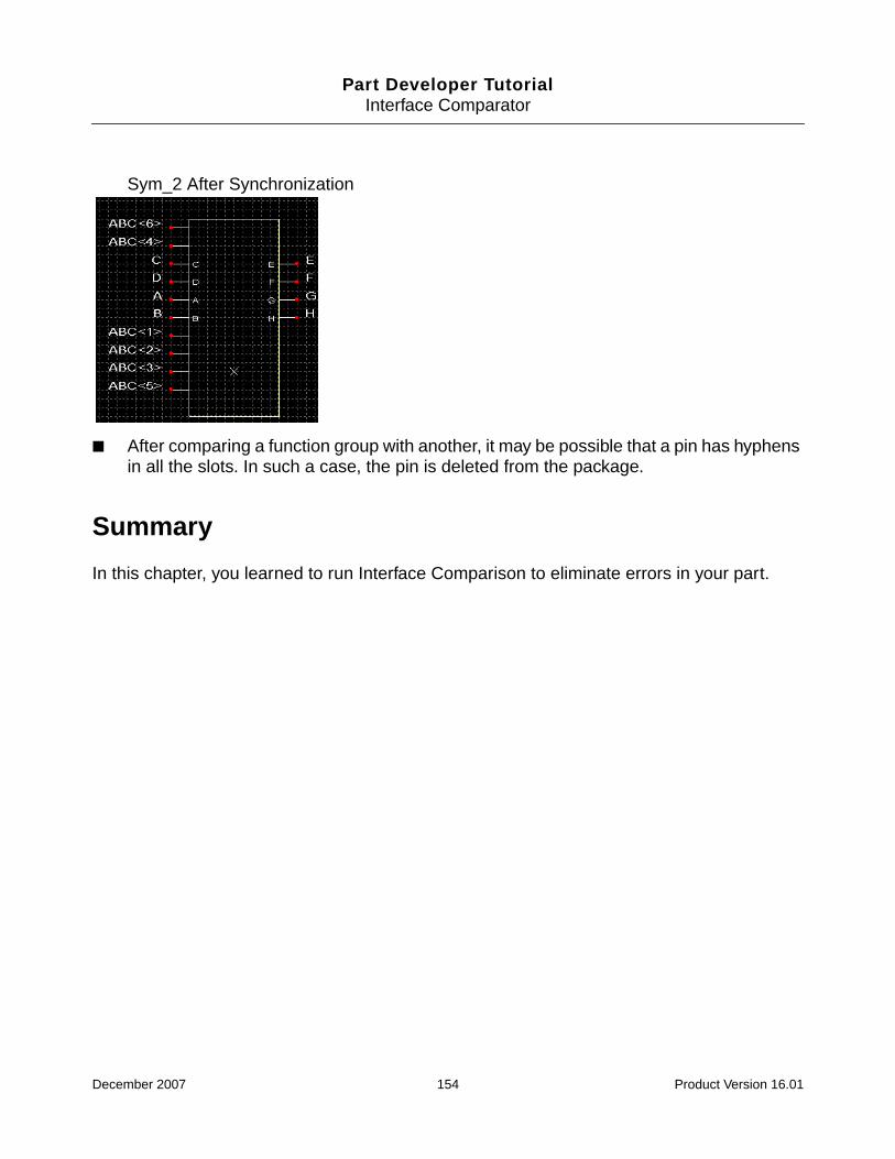
Part Developer TutorialInterface Comparator
Sym_2 After Synchronization
■ After comparing a function group with another, it may be possible that a pin has hyphensin all the slots. In such a case, the pin is deleted from the package.
Summary
In this chapter, you learned to run Interface Comparison to eliminate errors in your part.
December 2007 154 Product Version 16.01

Part Developer TutorialInterface Comparator
December 2007 155 Product Version 16.01


![]project-open[ Workflow Developer Tutorial Part 4](https://static.fdocuments.in/doc/165x107/54c853af4a7959d6058b45e7/project-open-workflow-developer-tutorial-part-4.jpg)