Part 1. ST60 Digital instruments - Velero Olaje 60 Digital Instruments Service... · Part 1. ST60...
36
Part 1. ST60 Instruments – Digital ST60 Instruments Service Manual 83142-1 i Part 1. ST60 Digital instruments D4468-2
-
Upload
trinhkhanh -
Category
Documents
-
view
240 -
download
0
Transcript of Part 1. ST60 Digital instruments - Velero Olaje 60 Digital Instruments Service... · Part 1. ST60...

Part 1. ST60 Instruments – Digital
ST60 Instruments Service Manual 83142-1 i
Part 1. ST60 Digital instruments
D4468-2

Part 1. ST60 Instruments – Digital
ii ST60 Instruments Service Manual 83142-1
ContentsST60 Digital instrument exploded view ............................................................................ iv
Chapter 1. ST60 Speed instrument ................................................................................... 1
Disassembly/reassembly ............................................................................................ 1
Self-test procedure ...................................................................................................... 1
Self test stage 1 ................................................................................................. 1
Self-test stage 2 ................................................................................................. 1
Self-test stage 4 ................................................................................................. 2
ST60 Speed spare parts list .......................................................................................... 3
ST60 Speed PCB details ............................................................................................. 4
Input/Output signals .......................................................................................... 4
ST60 Speed circuit diagram ............................................................................... 5
ST60 Speed PCB layout ............................................................................................. 6
ST60 Speed PCB component list ....................................................................... 7
Chapter 2. ST60 Depth instrument ................................................................................... 9
Disassembly/reassembly ............................................................................................ 9
Self-test procedure ...................................................................................................... 9
Self test stage 1 ................................................................................................. 9
Self-test stage 2 ................................................................................................. 9
Self-test stage 4 ............................................................................................... 10
ST60 Depth spare parts list ........................................................................................ 11
ST60 Depth PCB details ........................................................................................... 12
Input/Output signals ........................................................................................ 12
ST60 Depth circuit diagram ............................................................................. 13
ST60 Depth PCB layout ........................................................................................... 14
ST60 Depth PCB component list ..................................................................... 15
Chapter 3. ST60 Multi instrument .................................................................................. 17
Disassembly/reassembly .......................................................................................... 17
Self-test procedure .................................................................................................... 17
Self test stage 1 ............................................................................................... 17
Self-test stage 2 ............................................................................................... 17
NMEA I/O Testing .......................................................................................... 18
ST60 Multi spare parts list ......................................................................................... 19
ST60 Multi PCB details ............................................................................................ 20
Input/Output signals ........................................................................................ 20
ST60 Multi circuit diagram.............................................................................. 21
ST60 Multi PCB layout ............................................................................................ 22
ST60 Multi PCB component list ...................................................................... 23

Part 1. ST60 Instruments – Digital
ST60 Instruments Service Manual 83142-1 iii
Chapter 4. ST60 Tridata instrument ............................................................................... 25
Disassembly/reassembly .......................................................................................... 25
Self-test procedure .................................................................................................... 25
Self test stage 1 ............................................................................................... 25
Self-test stage 2 ............................................................................................... 25
Self-test stage 4 ............................................................................................... 26
ST60 Tridata spare parts list ...................................................................................... 27
ST60 Tridata PCB details .......................................................................................... 28
Input/Output signals ........................................................................................ 28
ST60 Tridata circuit diagram ........................................................................... 29
ST60 Tridata PCB layout .......................................................................................... 30
ST60 Tridata PCB component list .................................................................... 31

Part 1. ST60 Instruments – Digital
iv ST60 Instruments Service Manual 83142-1
ST60 Digital instrument exploded view
12
34
1. F
acia
bez
el 2
. Key
pad
3. F
acia
4. I
nner
key
pad
5. L
abel
6. L
CD d
ispl
ay 7
. Diff
user
8. R
efle
ctor
9. P
CB a
ssem
bly
10. C
ase
seal
Not
e:A
. It i
s re
com
men
ded
that
a n
ew c
ase
seal
(10)
is
fitt
ed o
n re
-ass
embl
y.
11. R
ear c
ase
12. W
ashe
r (x3
)13
. Scr
ew (x
11)
14. L
abel
(rea
r cas
e)15
. Gas
ket
16. F
lush
mou
nt b
ezel
17. S
crew
(x4)
18. F
lush
mou
nt s
eal
19. R
ear b
rack
et5
6
12 (x3)
13(x
3)To
rque
0.2
2Nm
(2lb
in)
13(x
8)To
rque
0.2
2Nm
(2lb
in)
78
910
(Not
e A
)11
1415
D44
48-1
2A
ssem
bly
16
17(x
4)
Torq
ue 0
.33N
m (3
lb in
) 18
19
Flus
h m
ount
ing
Figure 1: ST60 Speed, Depth, Multi and Tridata Digital Instrument exploded view

Part 1. ST60 Instruments – Chapter 1. Speed
A220
01
ST60 Instruments Service Manual 83142-1 1
Chapter 1. ST60 Speed instrument
Disassembly/reassemblyOn reassembly (refer to Figure 1), it is important that the PCB assembly module isfixed to the facia (3) using a torque of 0.22Nm (2lb in). Similarly, fixing the rear case(11) to the facia (3) must also be torqued to 0.22Nm (2lb in).Note: Failure to practice using the recommended torques may result in damage tothe facia inserts. It is also recommended a new case seal (10) is fitted on reassembly.
Self-test procedureThe ST60 Speed instrument has built-in self-test functions to aid fault diagnosis.
To access self-test mode, press Key 1 and Key 4 together for 4 seconds. When theunit beeps, immediately press Key 3 and Key 4 together momentarily. The unit willenter self-test stage 1.
Self test stage 1A. The unit should display “TEST1”
B. Audible Beep for 1 second.
C. There will be a SeaTalk transmission to check the transmit/receive circuits.
D. The EEPROM is tested.
The following failure codes may be generated:
Message Failure Mode Action
FAIL 1 SeaTalk Rx/Tx Check for damaged bucket connectors/rear-case pins.Check SeaTalk interface components around TR1, TR2and TR3.
FAIL 2 EEPROM failure Replace EEPROM (IC2)
If there is no audible beep, check TR11 and RN3 and the buzzer for damage. If thebeep is quiet, check R21.
If all test pass, “PASS” is shown on the display. Press Key 1 and Key 2 togethermomentarily to progress to self-test stage 2.
Self-test stage 2A. The unit should display “TEST 2” for 1 second.
B. Illumination will change between level 0 and level 3 every second.
C. Any key press sound cause audible beep.
D. LCD segments will cycle through the following sequence:
D4479-1
1 2 3 4

Part 1. ST60 Instruments – Chapter 1. SpeedA2
2001
2 ST60 Instruments Service Manual 83142-1
No fail codes are generated since stage 2 is an audio/visual check. The following can,however, be used as a guide to isolate a problem:
Failure Mode Action
No illumination Check TR14, TR13, TR15 and associated components.Check all LEDs.
Keypad Illumination failure Check TR14, TR13, R22 and R23.(LCD illumination will also be degraded) Check LED1-6 for open circuit.
Keypad illumination OK Check TR14, TR15, RN3, R24.but degraded LCD illumination Check LED 7 and 8 for open circuit.
No beep when key pressed Replace keyswitch.
LCD segment(s) missing completely Check LCD solder pins for poor/dry joints. Check IC3 for unsoldered pins.
Faint LCD segments Check LCD pins for shorts.Check IC3 for shorts.
Press Key 1 and Key 2 together momentarily to progress to self-test stage 4 (stage 3not supported on this instrument).
Self-test stage 4
Note: A known good transducer must be connected for this test.
A. The unit should display ‘TEST 4’ for 1 second.
B. Transducer test is performed.
Spin the paddle wheel within 15 seconds of entering this test. If the interface isworking correctly, “PASS” will be shown. Otherwise “FAIL 10” is shown.
If the test fails, do the following:
Check Failure Mode Action
Voltage at 12V_SPD No voltage or low voltage (<11.0) Check TR17, TR20, R63 and R64.with 12V battery supply.
L7 Open circuit Replace L7
D3 Open circuit Replace D3
Voltage at TEMP pin Outside acceptable range of Check L9 for open circuit0.76 to 1.00V (18 - 25 degrees C) Check R14
AVREF Outside acceptable range of Check TR4.2.5V +/- 0.25v Check R74, 17
Press Key 1 and Key 2 together momentarily to exit self-test.

Part 1. ST60 Instruments – Chapter 1. Speed
A220
01
ST60 Instruments Service Manual 83142-1 3
ST60 Speed spare parts listThe item numbers refer toFigure 1: ST60 Digital instrument exploded view
Item Spare/Accessory Description Part No. Comments
1 Facia bezel A25001
– Suncover, standard A25004 Not illustrated
2 Keypad, Speed A28019 Pack of 5
Facia with case seal, including A280133 Facia10 Case seal See A2802712 Washer (x3)13 Screw (x11) Torque to 0.22Nm (2lb in)
Inner keypad, including A280224 Inner keypad10 Case seal See A2802712 Washer (x3)13 Screw (x11) Torque to 0.22Nm (2lb in)
5 Display label, Speed A28031 Pack of 5
6 LCD display, Speed A28023 Also serves the Depthor Multi
PCB assembly, Speed, including A28010 Assembled module consisting of items 6, 7, 8, 9.
6 LCD display, Speed See A280237 Diffuser8 Reflector9 PCB assembly, Speed10 Case seal See A2802712 Washer (x3)13 Screw (x11) Torque to 0.22Nm (2lb in)
10 Case seal A28027 Pack of 5
Rear case assembly, including A2801410 Case seal See A2802711 Rear case13 Screw (x8) Torque to 0.22Nm (2lb in)
14 Label, Speed (rear case) A28035 Pack of 5
15 Gasket A28028 Pack of 5
16 Flush mount bezel A25002
Flush mount kit, including A25003 – Suncover, flush mount Not illustrated16 Flush mount bezel See A2500217 Screw (x4) Torque to 0.33Nm (3lb in)18 Flush mount seal19 Rear bracket

Part 1. ST60 Instruments – Chapter 1. SpeedA2
2001
4 ST60 Instruments Service Manual 83142-1
ST60 Speed PCB details
Input/Output signals(refer to Figure 2. ST60 Speed circuit diagram)
Rear case Signal Descriptionconnection
A (Red) BATT+_2 Nominal 12V DC supply
B (Screen) BATT-_2 OV
C (Yellow) STALK_2 Intermittent streams of (nominal) 12V pulses
D (Red) BATT+ Nominal 12V DC supply
E (Screen) BATT- OV
F (Yellow) STALK Intermittent streams of (nominal) 12V pulses
G (Red) 12V_SPD Approximately 11.2V DC out
H (Green) SPD With transducer attached, spinning paddle-wheel produces pulsesapproximately 11.2V DC in amplitude @ 5.5Hz/Knot.
J (Screen) OV OV
K (White) TEMP With transducer attached, voltage here is dependant ontemperature. Approximately 1.8v at 0 degrees C.
L (Brown) OVANA OV
Rear case connections to ST60 Speed instrument D4480-1
SPEED
DEPTH
L K J H
G
AB
C DE
F

Part 1. ST60 Instruments – Chapter 1. Speed
A220
01
ST60 Instruments Service Manual 83142-1 5
ST60 Speed circuit diagram
D44
53-1
Figure 2. ST60 Speed circuit diagram

Part 1. ST60 Instruments – Chapter 1. SpeedA2
2001
6 ST60 Instruments Service Manual 83142-1
ST60 Speed PCB layout
Taken from Drawing No: 4315-004 Issue: D Date: 01-10-98 D4451-1

Part 1. ST60 Instruments – Chapter 1. Speed
A220
01
ST60 Instruments Service Manual 83142-1 7
ST60 Speed PCB component list
D4452-1Taken from Drawing No: 4315-004 Issue: D Date: 01-10-98
ST60 SPEED Digital

Part 1. ST60 Instruments – Chapter 1. SpeedA2
2001
8 ST60 Instruments Service Manual 83142-1

Part 1. ST60 Instruments – Chapter 2. Depth
A220
02
ST60 Instruments Service Manual 83142-1 9
Chapter 2. ST60 Depth instrument
Disassembly/reassemblyOn reassembly (refer to Figure 1), it is important that the PCB assembly module isfixed to the facia (3) using a torque of 0.22Nm (2lb in). Similarly, fixing the rear case(11) to the facia (3) must also be torqued to 0.22Nm (2lb in).Note: Failure to practice using the recommended torques may result in damage tothe facia inserts. It is also recommended a new case seal (10) is fitted on reassembly.
Self-test procedureThe ST60 Depth instrument has built-in self-test functions to aid fault diagnosis.
To access self-test mode, press Key 1 and Key 4 together for 4 seconds. When theunit beeps, immediately press Key 3 and Key 4 together momentarily. The unit willenter self-test stage 1.
Self test stage 1A. The unit should display “TEST 1”
B. Audible Beep for 1 second.
C. There will be a SeaTalk transmission to check the transmit/receive circuits.
D. The EEPROM is tested.
The following failure codes may be generated:
Message Failure Mode Action
FAIL 1 SeaTalk Rx/Tx Check for damaged bucket connectors/rear-case pins.Check SeaTalk interface components around TR1, TR2and TR3.
FAIL 2 EEPROM failure Replace EEPROM (IC2).
If there is no audible beep, check TR11 and RN3 and the buzzer for damage. If thebeep is quiet, check R21.
If all test pass, “PASS” is shown on the display. Press Key 1 and Key 2 togethermomentarily to progress to self-test stage 2.
Self-test stage 2A. The unit should display “TEST 2” for 1 second.
B. Illumination will change between level 0 and level 3 every second.
C. Any key press sound cause audible beep.
D. LCD segments will cycle through the following sequence:
D4479-1
1 2 3 4

Part 1. ST60 Instruments – Chapter 2. DepthA2
2002
10 ST60 Instruments Service Manual 83142-1
No fail codes are generated since stage 2 is an audio/visual check. The following can,however, be used as a guide to isolate a problem:
Failure Mode Action
No illumination Check TR14, TR13, TR15 and associated components.Check all LEDs.
Keypad Illumination failure Check TR14, TR13, R22 and R23.(LCD illumination will also be degraded) Check LED1-6 for open circuit.
Keypad illumination OK Check TR14, TR15, RN3, R24.but degraded LCD illumination Check LED 7 and 8 for open circuit.
No beep when key pressed Replace keyswitch.
LCD segment(s) missing completely Check LCD solder pins for poor/dry joints.Check IC3 for unsoldered pins.
Faint LCD segments Check LCD pins for shorts.Check IC3 for shorts.
Press Key 1 and Key 2 together momentarily to progress to self-test stage 4 (stage 3not supported on this instrument).
Self-test stage 4
Note: For this test, a known good transducer must be connected and placed in waterwhere an echo can be detected. Alternatively, and echo simulator can be used.
A. The unit should display “TEST 4” for 1 second.
B. Transducer test is performed.
If the interface is working correctly, “PASS” will be shown within 15 seconds.Otherwise “FAIL 8” is shown.
If the test fails, do the following:
Check Failure Mode Action
Pulses at pins 8 and 10 of IC4 No pulses Check R68, 76, 77.Check IC4 and IC5 and replace if suspect (tracepulses from IC3).
Pulses at drain of TR5 No pulses Check L5 and R19 for open circuit.Replace TR5.Replace T1.
Pulses at drain of TR6 No pulses Check L5 and R19 for open circuit.Replace TR6.Replace T1.
Pulses at DEPTH+ and DEPTH- No pulses Check C11 and C12 for open circuit.Replace T1
Depth receiver output pulses No pulses Fault diagnosis of the depth receiver circuitat pin 11 of IC5 requires specialist knowledge and the units
should be returned to Raytheon Marine Ltd.
Press Key 1 and Key 2 together momentarily to exit self-test.

Part 1. ST60 Instruments – Chapter 2. Depth
A220
02
ST60 Instruments Service Manual 83142-1 11
ST60 Depth spare parts listThe item numbers refer toFigure 1: ST60 Digital instrument exploded view
Item Spare/Accessory Description Part No. Comments
1 Facia bezel A25001
– Suncover,standard A25004 Not illustrated
2 Keypad, Depth A28019 Pack of 5
Facia with case seal, including A280133 Facia10 Case seal See A2802712 Washer (x3)13 Screw (x11) Torque to 0.22Nm (2lb in)
Inner keypad, including A280224 Inner keypad10 Case seal See A2802712 Washer (x3)13 Screw (x11) Torque to 0.22Nm (2lb in)
5 Display label, Depth A28030 Pack of 5
6 LCD display, Depth A28023 Also serves the Speedor Multi
PCB assembly, Depth, including A28009 Assembled module consistingof items 6, 7, 8, 9.
6 LCD display, Depth See A280237 Diffuser8 Reflector9 PCB assembly, Depth10 Case seal See A2802712 Washer (x3)13 Screw (x11) Torque to 0.22Nm (2lb in)
10 Case seal A28027 Pack of 5
Rear case assembly, including A2801410 Case seal See A2802711 Rear case13 Screw (x8)
14 Label, Depth (rear case) A28036 Pack of 5
15 Gasket A28028 Pack of 5
16 Flush mount bezel A25002
Flush mount kit, including A25003 – Suncover, flush mount Not illustrated16 Flush mount bezel See A2500217 Screw (x4) Torque to 0.33Nm (3lb in)18 Flush mount seal19 Rear bracket

Part 1. ST60 Instruments – Chapter 2. DepthA2
2002
12 ST60 Instruments Service Manual 83142-1
ST60 Depth PCB details
Input/Output signals(refer to Figure 3. ST60 Depth circuit diagram)
Rear case Signal Descriptionconnection
A (Red) BATT+_2 Nominal 12V DC supply
B (Screen) BATT-_2 OV
C (Yellow) STALK_2 Intermittent streams of (nominal) 12V pulses
D (Red) BATT+ Nominal 12V DC supply
E (Screen) BATT- OV
F (Yellow) STALK Intermittent streams of (nominal) 12V pulses
G (Black) DEPTH- Intermittent pulses of 200KHz, approximately 400us wide, 300Vp-p
H (Blue) DEPTH+ Intermittent pulses of 200KHz, approximately 400us wide, 300Vp-p
J (Screen) DEPTH_GND OV
Rear case connections to ST60 Depth instrument D4481-1
SPEED
DEPTH
G
HJ
AB
C DE
F
Part 1. ST60 Instruments – Chapter 2. Depth
A220
02
ST60 Instruments Service Manual 83142-1 13
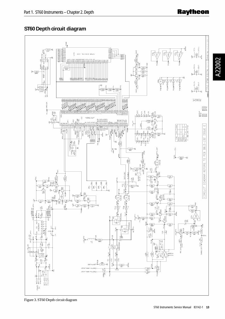
ST60 Depth circuit diagram
D445
6-1
Figure 3. ST60 Depth circuit diagram

Part 1. ST60 Instruments – Chapter 2. DepthA2
2002
14 ST60 Instruments Service Manual 83142-1
ST60 Depth PCB layout
Taken from Drawing No: 4316-003 Issue: D Date: 01-10-98 D4454-1
ST60DEPTHDigital

Part 1. ST60 Instruments – Chapter 2. Depth
A220
02
ST60 Instruments Service Manual 83142-1 15
ST60 Depth PCB component list
D4455-1Taken from Drawing No: 4316-003 Issue: D Date: 01-10-98
ST60 DEPTH Digital

Part 1. ST60 Instruments – Chapter 2. DepthA2
2002
16 ST60 Instruments Service Manual 83142-1
Part 1. ST60 Instruments – Chapter 3. Multi
A220
03
ST60 Instruments Service Manual 83142-1 17
Chapter 3. ST60 Multi instrument
Disassembly/reassemblyOn reassembly (refer to Figure 1), it is important that the PCB assembly module isfixed to the facia (3) using a torque of 0.22Nm (2lb in). Similarly, fixing the rear case(11) to the facia (3) must also be torqued to 0.22Nm (2lb in).Note: Failure to practice using the recommended torques may result in damage tothe facia inserts. It is also recommended a new case seal (10) is fitted on reassembly.
Self-test procedureThe ST60 Multi instrument has built-in self-test functions to aid fault diagnosis.
To access self-test mode, press Key 1 and Key 4 together for 4 seconds. When theunit beeps, immediately press Key 3 and Key 4 together momentarily. The unit willenter self-test stage 1.
Self test stage 1A. The unit should display “TEST 1”
B. Audible Beep for 1 second.
C. There will be a seatalk transmission to check the transmit/receive circuits.
D. The EEPROM is tested.
The following failure codes may be generated:
Message Failure Mode Action
FAIL 1 Seatalk Rx/Tx Check for damaged bucket connectors/rear-case pins.Check SeaTalk interface components around TR1, TR2and TR3.
FAIL 2 EEPROM failure Replace EEPROM (IC2)
If there is no audible beep, check TR11 and RN3 and the buzzer for damage. If thebeep is quiet, check R21.
If all test pass, “PASS” is shown on the display. Press Key 1 and Key 2 togethermomentarily to progress to self-test stage 2.
Self-test stage 2A. The unit should display “TEST 2” for 1 second.
B. Illumination will change between level 0 and level 3 every second.
C. Any key press sound cause audible beep.
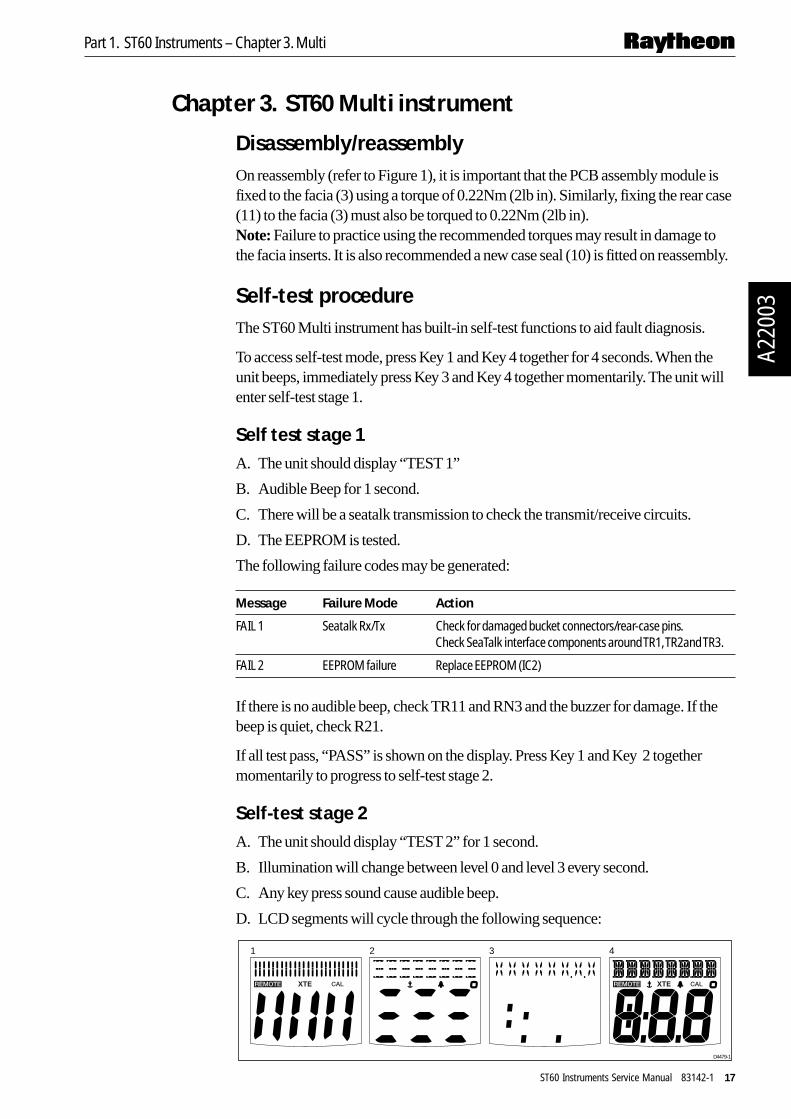
D. LCD segments will cycle through the following sequence:
D4479-1
1 2 3 4

Part 1. ST60 Instruments – Chapter 3. MultiA2
2003
18 ST60 Instruments Service Manual 83142-1
No fail codes are generated since stage 2 is an audio/visual check. The following can,however, be used as a guide to isolate a problem:
Failure Mode Action
No illumination Check TR14, TR13, TR15 and associated components.Check all LEDs.
Keypad Illumination failure Check TR14, TR13, R22 and R23.(LCD illumination will also be degraded) Check LED1-6 for open circuit.
Keypad illumination OK Check TR14, TR15, RN3, R24.but degraded LCD illumination Check LED 7 and 8 for open circuit.
No beep when key pressed Replace keyswitch.
LCD segment(s) missing completely Check LCD solder pins for poor/dry joints.Check IC3 for unsoldered pins.
Faint LCD segments Check LCD pins for shorts.Check IC3 for shorts.
Press Key 1 and Key 2 together momentarily to progress to exit self-test (stages 3and 4 are not supported on this instrument).
NMEA I/O Testing
Note that there is no self-test for NMEA input/output. As a guidline, if NMEA hasfailed, do the following:
1. Ensure that NMEA output has been turned ON in user CAL.
2. Ensure that the instrument is receiving seatalk data for translation to NMEA (e.g.Heading, Latitude, Longitude etc...)
3. Voltage at NMEA_OUT+ should be approx 11.2v with 12v battery supply.Current supplied from this pin to BATT- should limit at approx.80mA. If there isa problem with this supply, check TR18, TR19 and associated components.
4. Connect a dummy load (1K resistor) across NMEA_OUT+ and NMEA_OUT-and check for pulses at NMEA_OUT- If no pulses are seen, check R18 and TR5.
5. Disconnect dummy load and connect NMEA outputs to corresponding NMEAinputs. Check for pulses at the junction of R59 and R60 (TP192). If no pulses areseen, check R55-58, L7 and IC8.
6. Check the final stage output at TR4b (TP116)

Part 1. ST60 Instruments – Chapter 3. Multi
A220
03
ST60 Instruments Service Manual 83142-1 19
ST60 Multi spare parts listThe item numbers refer toFigure 1: ST60 Digital instrument exploded view
Item Spare/Accessory Description Part No. Comments
1 Facia bezel A25001
– Suncover,standard A25004 Not illustrated
2 Keypad, Multi A28021 Pack of 5
Facia with case seal, including A280133 Facia10 Case seal See A2802712 Washer (x3)13 Screw (x11) Torque to 0.22Nm (2lb in)
Inner keypad, including A280224 Inner keypad10 Case seal See A2802712 Washer (x3)13 Screw (x11) Torque to 0.22Nm (2lb in)
5 Display label, Multi A28029 Pack of 5
6 LCD display, Multi A28023 Also serves the Speedor Depth
PCB assembly, Multi, including A28012 Assembled module con-sisting of items 6, 7, 8, 9.
6 LCD display, Multi See A280237 Diffuser8 Reflector9 PCB assembly, Multi10 Case seal See A2802712 Washer (x3)13 Screw (x11) Torque to 0.22Nm (2lb in)
10 Case seal A28027 Pack of 5
Rear case assembly, including A2801410 Case seal See A2802711 Rear case13 Screw (x8) Torque to 0.22Nm (2lb in)
14 Label, Multi (rear case) A28034 Pack of 5
15 Gasket A28028 Pack of 5
16 Flush mount bezel A25002
Flush mount kit, including A25003 – Suncover, flush mount Not illustrated16 Flush mount bezel See A2500217 Screw (x4) Torque to 0.33Nm (3lb in)18 Flush mount seal19 Rear bracket

Part 1. ST60 Instruments – Chapter 3. MultiA2
2003
20 ST60 Instruments Service Manual 83142-1
ST60 Multi PCB details
Input/Output signals(refer to Figure 4. ST60 Multi circuit diagram)
Rear case Signal Descriptionconnection
A (Red) BATT+_2 Nominal 12V DC supply
B (Screen) BATT-_2 OV
C (Yellow) STALK_2 Intermittent streams of (nominal) 12V pulses
D (Red) BATT+ Nominal 12V DC supply
E (Screen) BATT- OV
F (Yellow) STALK Intermittent streams of (nominal) 12V pulses
G (Blue) NMEA_OUT- Open-drain pull-down
H (Red) NMEA_OUT+ Approximately 11.2v, current limited to 80mA
J (Blue) NMEA_IN- Isolated opto input, 550 ohms
K (Red) NMEA_IN+ Isolated opto input, 550 ohms
Rear case connections to ST60 Multi instrument D4482-1
NMEAIN
NMEA
OUT
G
H J
K
AB
C DE
F

Part 1. ST60 Instruments – Chapter 3. Multi
A220
03
ST60 Instruments Service Manual 83142-1 21
ST60 Multi circuit diagram
D446
2-1
Figure 4. ST60 Multi circuit diagram

Part 1. ST60 Instruments – Chapter 3. MultiA2
2003
22 ST60 Instruments Service Manual 83142-1
ST60 Multi PCB layout
Taken from Drawing No: 4321-002 Issue: D Date: 01-10-98 D4460-1
ST60MULTIDigital

Part 1. ST60 Instruments – Chapter 3. Multi
A220
03
ST60 Instruments Service Manual 83142-1 23
ST60 Multi PCB component list
D4461-1Taken from Drawing No: 4321-002 Issue: D Date: 01-10-98
ST60 MULTI Digital

Part 1. ST60 Instruments – Chapter 3. MultiA2
2003
24 ST60 Instruments Service Manual 83142-1

Part 1. ST60 Instruments – Chapter 4. Tridata
A220
04
ST60 Instruments Service Manual 83142-1 25
Chapter 4. ST60 Tridata instrument
Disassembly/reassemblyOn reassembly (refer to Figure 1), it is important that the PCB assembly module isfixed to the facia (3) using a torque of 0.22Nm (2lb in). Similarly, fixing the rear case(11) to the facia (3) must also be torqued to 0.22Nm (2lb in).Note: Failure to practice using the recommended torques may result in damage tothe facia inserts. It is also recommended a new case seal (10) is fitted on reassembly.
Self-test procedureThe ST60 Tridata instrument has built-in self-test functions to aid fault diagnosis.
To access self-test mode, press Key 1 and Key 4 together for 4 seconds. When theunit beeps, immediately press Key 3 and Key 4 together momentarily. The unit willenter self-test stage 1.
Self test stage 1A. The unit should display “TEST 1”
B. Audible Beep for 1 second.
C. There will be a SeaTalk transmission to check the transmit/receive circuits.
D. The EEPROM is tested.
The following failure codes may be generated:
Message Failure Mode Action
FAIL 1 SeaTalk Rx/Tx Check for damaged bucket connectors/rear-case pins.Check SeaTalk interface components around TR1, TR2and TR3.
FAIL 2 EEPROM failure Replace EEPROM (IC2)
If there is no audible beep, check TR11 and RN3 and the buzzer for damage. If thebeep is quiet, check R21.
If all test pass, “PASS” is shown on the display. Press Key 1 and Key 2 togethermomentarily to progress to self-test stage 2.
Self-test stage 2A. The unit should display “TEST 2” for 1 second.
B. Illumination will change between level 0 and level 3 every second.
C. Any key press sound cause audible beep.
D. LCD segments will cycle through the following sequence:
D4484-1
1 2 3 4

Part 1. ST60 Instruments – Chapter 4. TridataA2
2004
26 ST60 Instruments Service Manual 83142-1
No fail codes are generated since stage 2 is an audio/visual check. The following can,however, be used as a guide to isolate a problem:
Failure Mode Action
No illumination Check TR14, TR13, TR15 and associated components. Check all LEDs.
Keypad Illumination failure (LCD Check TR14, TR13, R22 and R23.illumination will also be degraded). Check LED1-6 for open circuit.
Keypad illumination OK Check TR14, TR15, RN3, R24.but degraded LCD illumination. Check LED 7 and 8 for open circuit.
No beep when key pressed. Replace keyswitch.
LCD segment(s) missing Check LCD solder pins for poor/dry joints.completely. Check IC3 for unsoldered pins.
Faint LCD segments Check LCD pins for shorts.Check IC3 for shorts.
Press Key 1 and Key 2 together momentarily to progress to self-test stage 4 (stage 3not supported on this instrument).
Self-test stage 4Note: A known good speed and depth transducer must be connected for this test.
A. The unit should display ‘TEST 4’ for 1 second.
B. Transducer tests are performed.
Spin the paddle wheel within 15 seconds of entering this test. If there is a problem withthe speed interface “FAIL 10” is shown and the following tests should be carried out.
Check Failure Mode Action
Voltage at 12V_SPD No voltage or low voltage (<11.0) Check TR17, TR20, R63 and R64.with 12V battery supply.
L7 Open circuit Replace L7.
D3 Open circuit Replace D3.
Voltage at TEMP pin Outside acceptable range of Check L9 for open circuit. 0.76 to 1.00V (18 - 25 degrees C) Check R14.
AVREF Outside acceptable range of 2.5V +/- 0.25v Check TR4. Check R74, 17.
Provided the depth transducer is in water where a good echo should be seen, the testwill pass, otherwise “FAIL 8” is shown and the following tests should be carried out:
Check Failure Mode Action
Pulses at pins 8 and 10 of IC4 No pulses Check R68, 76, 77. Check IC4 and IC5 andreplace if suspect (trace pulses from IC3).
Pulses at drain of TR5 No pulses Check L5 and R19 for open circuit.Replace TR5. Replace T1.
Pulses at drain of TR6 No pulses Check L5 and R19 for open circuit.Replace TR6. Replace T1.
Pulses at DEPTH+ and DEPTH- No pulses Check C11 and C12 for open circuit. Replace T1
Depth receiver output pulses No pulses Fault diagnosis of the depth receiver circuitat pin 11 of IC5 requires specialist knowledge and the units
should be returned to Raytheon Marine Ltd.
Press Key 1 and Key 2 together momentarily to exit self-test.

Part 1. ST60 Instruments – Chapter 4. Tridata
A220
04
ST60 Instruments Service Manual 83142-1 27
ST60 Tridata spare parts listThe item numbers refer toFigure 1: ST60 Digital Instrument exploded view
Item Spare/Accessory Description Part No. Comments
1 Facia bezel A25001
– Suncover,standard A25004 Not illustrated
2 Keypad, Tridata A28020 Pack of 5
Facia with case seal, including A280133 Facia10 Case seal See A2802712 Washer (x3)13 Screw (x11) Torque to 0.22Nm (2lb in)
Inner keypad, including A280224 Inner keypad10 Case seal See A2802712 Washer (x3)13 Screw (x11) Torque to 0.22Nm (2lb in)
5 Display label, Tridata A28032 Pack of 5
6 LCD display, Tridata A28024
PCB assembly, Tridata, including A28011 Assembled module con-sisting of items 6, 7, 8, 9.
6 LCD display, Tridata See A280247 Diffuser8 Reflector9 PCB assembly, Tridata10 Case seal See A2802712 Washer (x3)13 Screw (x11) Torque to 0.22Nm (2lb in)
10 Case seal A28027 Pack of 5
Rear case assembly, including A2801410 Case seal See A2802711 Rear case13 Screw (x8) Torque to 0.22Nm (2lb in)
14 Label, Tridata (rear case) A28033 Pack of 5
15 Gasket A28028 Pack of 5
16 Flush mount bezel A25002
Flush mount kit, including A25003 – Suncover, flush mount Not illustrated16 Flush mount bezel See A2500217 Screw (x4) Torque to 0.33Nm (3lb in)18 Flush mount seal19 Rear bracket

Part 1. ST60 Instruments – Chapter 4. TridataA2
2004
28 ST60 Instruments Service Manual 83142-1
ST60 Tridata PCB details
Input/Output signals(refer to Figure 5. ST60 Tridata circuit diagram)
Rear case Signal Descriptionconnection
A (Red) BATT+_2 Nominal 12V DC supply
B (Screen) BATT-_2 OV
C (Yellow) STALK_2 Intermittent streams of (nominal) 12V pulses
D (Red) BATT+ Nominal 12V DC supply
E (Screen) BATT- OV
F (Yellow) STALK Intermittent streams of (nominal) 12V pulses
G (Red) 12V_SPD Approximately 11.2V DC out
H (Green) SPD With transducer attached, spinning paddle-wheel produces pulsesapproximately 11.2V DC in amplitude at 5.5Hz/Knot.
J (Screen) OV OV
K (White) TEMP With transducer attached, voltage here is dependant ontemperature. Approximately 1.8v at 0 degrees C.
L (Brown) OVANA OV
M (Black) DEPTH- Intermittent pulses of 200KHz, approximately 400us wide, 300Vp-p
N (Blue) DEPTH+ Intermittent pulses of 200KHz, approximately 400us wide, 300Vp-p
P (Screen) DEPTH_GND O V
Rear case connections to ST60 Tridata instrument D4483-1
SPEED
DEPTH
M
NP
L K J H
G
AB
C DE
F

Part 1. ST60 Instruments – Chapter 4. Tridata
A220
04
ST60 Instruments Service Manual 83142-1 29
ST60 Tridata circuit diagram
D445
9-1
Figure 5. ST60 Tridata circuit diagram

Part 1. ST60 Instruments – Chapter 4. TridataA2
2004
30 ST60 Instruments Service Manual 83142-1
ST60 Tridata PCB layout
Taken from Drawing No: 4317-002 Issue: E Date: 09-10-98 D4457-1
ST60TRIDATADigital

Part 1. ST60 Instruments – Chapter 4. Tridata
A220
04
ST60 Instruments Service Manual 83142-1 31
ST60 Tridata PCB component list
D4458-1Taken from Drawing No: 4317-002 Issue: E Date: 09-10-98
ST60 TRIDATA Digital

Part 1. ST60 Instruments – Chapter 4. TridataA2
2004
32 ST60 Instruments Service Manual 83142-1