Parallel RLC Network - Virginia Tech · Parallel RLC Network . ... Boundary Conditions ... Note...
14
Parallel RLC Network
Transcript of Parallel RLC Network - Virginia Tech · Parallel RLC Network . ... Boundary Conditions ... Note...

Parallel RLC Network

Objective of Lecture Derive the equations that relate the voltages across and the
currents flowing through a resistor, an inductor, and a capacitor in parallel as:
the unit step function associated with voltage or current source changes from 1 to 0 or
a switch disconnects a voltage or current source in the circuit.
Describe the solution to the 2nd order equations when the condition is:
Overdamped
Critically Damped
Underdamped

RLC Network A parallel RLC network where the current source is
switched out of the circuit at t = to.
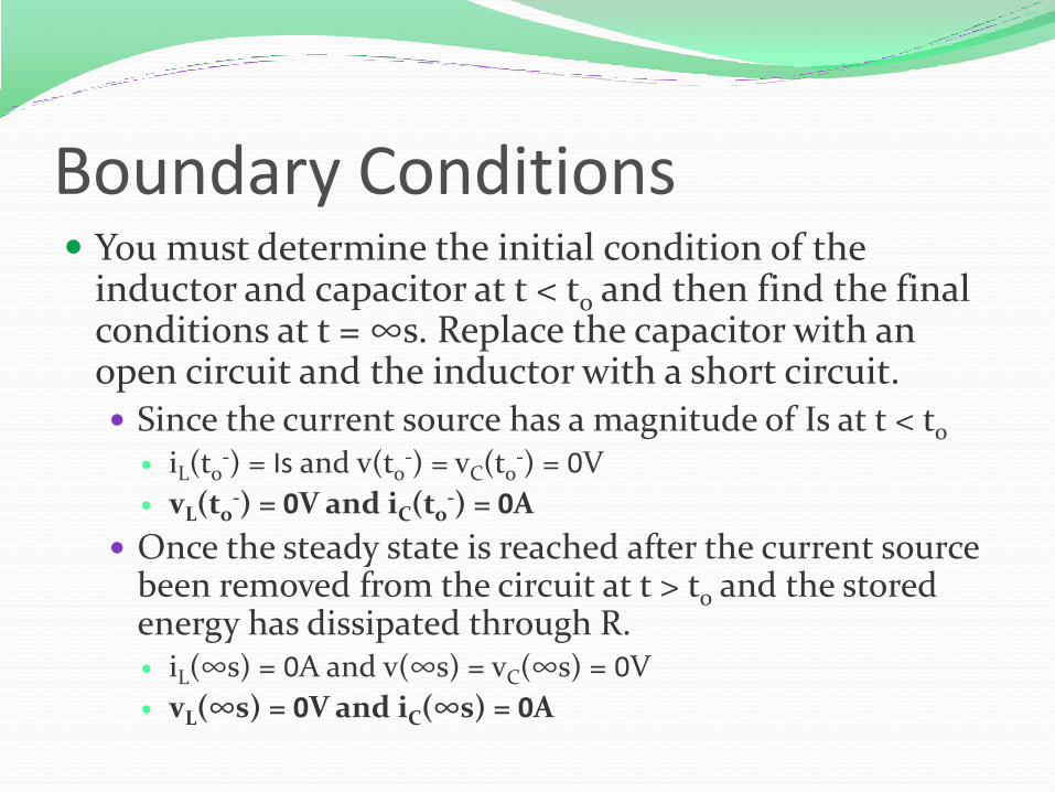
Boundary Conditions You must determine the initial condition of the
inductor and capacitor at t < to and then find the final conditions at t = ∞s. Replace the capacitor with an open circuit and the inductor with a short circuit. Since the current source has a magnitude of Is at t < to
iL(to-) = Is and v(to
-) = vC(to-) = 0V
vL(to-) = 0V and iC(to
-) = 0A
Once the steady state is reached after the current source been removed from the circuit at t > to and the stored energy has dissipated through R. iL(∞s) = 0A and v(∞s) = vC(∞s) = 0V
vL(∞s) = 0V and iC(∞s) = 0A

Selection of Parameter Initial Conditions
iL(to-) = Is and v(to
-) = vC(to-) = 0V
vL(to-) = 0V and iC(to
-) = 0A
Final Conditions iL(∞s) = 0A and v(∞s) = vC(∞s) = oV
vL(∞s) = 0V and iC(∞s) = 0A
Since the current through the inductor is the only parameter that has a non-zero boundary condition, the first set of solutions will be for iL(t).

Kirchoff’s Current Law
0)()(1)(
0)()()(
)()()(
0)(
)()(
)()()()(
0)()()(
2
2
2
2
LC
ti
dt
tdi
RCdt
tid
tidt
tdi
R
L
dt
tidLC
dt
tdiLtvtv
dt
tdvCti
R
tv
tvtvtvtv
tititi
LLL
LLL
LL
CL
R
CLR
CLR

General Solution
LCRCRCs
LCRCRCs
1
2
1
2
1
1
2
1
2
1
2
2
2
1
0112
LCs
RCs

LC
RC
o
1
2
1
22
2
22
1
o
o
s
s
02 22 oss
Note that the equation for the natural frequency of the RLC circuit is the same whether the components are in series or in parallel.
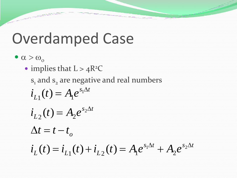
Overdamped Case > o
implies that L > 4R2C s1 and s2 are negative and real numbers
tsts
LLL
o
ts
L
ts
L
eAeAtititi
ttt
eAti
eAti
21
2
1
2121
22
11
)()()(
)(
)(

Critically Damped Case o
implies that L = 4R2C
s1 = s2 = - = -1/2RC
tt
L teAeAti 21)(

Underdamped Case < o
implies that L < 4R2C
]sincos[)( 21
22
22
2
22
1
tAtAeti
js
js
dd
t
L
od
do
do

Solve for Coefficients A1 and A2 Use the boundary conditions at to
- and t = ∞s to solve
for A1 and A2.
Since the current through an inductor must be a continuous function of time.
Also know that
SoL Iti )(
S
ssss
SoLoLoLoL
IAAeAeA
Ititititi
21
0
2
0
1
21
21
)()()()(
0
0)()()(
)(
2211
0
22
0
11
21
21
AsAseAseAs
titidt
d
dt
tdiLtv
ssss
oLoLoL
oL

Other Voltages and Currents Once current through the inductor is known:
Rtvti
dt
tdvCti
tvtvtv
dt
tdiLtv
RR
CC
RCL
LL
/)()(
)()(
)()()(
)()(
Summary The set of solutions when t > to for the current through the
inductor in a RLC network in parallel was obtained.
Selection of equations is determine by comparing the natural frequency o to .
Coefficients are found by evaluating the equation and its first derivation at t = to
-.
The current through the inductor is equal to the initial condition when t < to
Using the relationships between current and voltage, the voltage across the inductor and the voltages and currents for the capacitor and resistor can be calculated.