PARALLEL KINEMATICS MACHINE TOOLS: OVERVIEW- FROM ...
14
© copyright FACULTY of ENGINEERING ‐ HUNEDOARA, ROMANIA 111 1. Zoran PANDILOV, 2. Vladimir DUKOVSKI PARALLEL KINEMATICS MACHINE TOOLS: OVERVIEW‐ FROM HISTORY TO THE FUTURE 1,2. UNIVERSITY “SV.KIRIIL IMETODIJ”, FACULTY OF MECHANICAL ENGINEERING‐SKOPJE,MK‐1000, SKOPJE, MACEDONIA ABSTRACT: Recently parallel kinematics machine tools attracted the attention due to their theoretically high motion dynamics potential, accuracy and stiffness due to their closed loop structure and no error accumulation characteristics. This paper gives a survey of the development of the parallel kinematics machine tools, their performances and their practical application compared with serial machine tools KEYWORDS: parallel kinematics machine tools, performances, application INTRODUCTION Parallel kinematics manipulators have attracted the attention in research institutions and industry due to their high theoretical dynamics potential, structural rigidity and high accuracy due to the closed kinematic loops and no error accumulating characteristics. Parallel manipulator also could be named as hexapod, a Stewart platform, Gough platform, Stewart‐Gough platform, a parallel kinematic machine (PKM) or a parallel robot. The first prototypes of parallel kinematics machine (PKM) tools were introduced to the public in 1994 by Ingersoll and Ginddings & Lewis (fig.1 and fig 2). During the last decade, according [27] more than 100 different parallel mechanical architectures have been built, mostly as prototypes or academic studies. Although more than 15 years passed since the first commercial parallel kinematics machine tools were introduced, they are not widely accepted in the industry. There are two reasons for that. First, from the beginning of their appearance it became obvious that implementation of their theoretical capabilities in practice introduces many new problems. The second reason is the psychological arguments like: lack of trust in the new, strange looking technology, reluctance to be first to try out the new technology, lack of accepted standards for assessing the users value of the parallel kinematics machine tools [38]. a) b) Figure 1. Schemes of parallel kinematics machine tools a) Ingersoll's "Octahedral Hexapod b) Giddings & Lewis' "Variax" [54] a) b) Figure 2. Photos of parallel kinematics machine tools a) Ingersoll's "Octahedral Hexapod b) Giddings & Lewis' "Variax" [54]
-
Upload
duongduong -
Category
Documents
-
view
215 -
download
1
Transcript of PARALLEL KINEMATICS MACHINE TOOLS: OVERVIEW- FROM ...

© copyright FACULTY of ENGINEERING ‐ HUNEDOARA, ROMANIA 111
1. Zoran PANDILOV, 2. Vladimir DUKOVSKI
PARALLEL KINEMATICS MACHINE TOOLS: OVERVIEW‐ FROM HISTORY TO THE FUTURE
1,2. UNIVERSITY “SV. KIRIIL I METODIJ”, FACULTY OF MECHANICAL ENGINEERING‐SKOPJE, MK‐1000, SKOPJE, MACEDONIA
ABSTRACT: Recently parallel kinematics machine tools attracted the attention due to their theoretically high motion dynamics potential, accuracy and stiffness due to their closed loop structure and no error accumulation characteristics. This paper gives a survey of the development of the parallel kinematics machine tools, their performances and their practical application compared with serial machine tools KEYWORDS: parallel kinematics machine tools, performances, application INTRODUCTION
Parallel kinematics manipulators have attracted the attention in research institutions and industry due to their high theoretical dynamics potential, structural rigidity and high accuracy due to the closed kinematic loops and no error accumulating characteristics.
Parallel manipulator also could be named as hexapod, a Stewart platform, Gough platform, Stewart‐Gough platform, a parallel kinematic machine (PKM) or a parallel robot.
The first prototypes of parallel kinematics machine (PKM) tools were introduced to the public in 1994 by Ingersoll and Ginddings & Lewis (fig.1 and fig 2). During the last decade, according [27] more than 100 different parallel mechanical architectures have been built, mostly as prototypes or academic studies.
Although more than 15 years passed since the first commercial parallel kinematics machine tools were introduced, they are not widely accepted in the industry.
There are two reasons for that. First, from the beginning of their appearance it became obvious that implementation of their theoretical capabilities in practice introduces many new problems.
The second reason is the psychological arguments like: � lack of trust in the new, strange looking technology, � reluctance to be first to try out the new technology, � lack of accepted standards for assessing the users value of the parallel kinematics machine tools
[38].
a) b) Figure 1. Schemes of parallel kinematics machine tools a) Ingersoll's
"Octahedral Hexapod b) Giddings & Lewis' "Variax" [54]
a) b) Figure 2. Photos of parallel kinematics machine tools a) Ingersoll's "Octahedral
Hexapod b) Giddings & Lewis' "Variax" [54]

ANNALS OF FACULTY ENGINEERING HUNEDOARA – International Journal Of Engineering
Tome X (Year 2012). Fascicule 2. ISSN 1584 – 2665 112
Additionally there are highly antagonistic opinions about parallel kinematics machine tools technology. The concept is claimed to be inferior to serial machines and practically not useful [42] or called the innovation focus on the METAV fair 2000 in Düsseldorf, Germany [23].
The aim of this paper is to give a survey of the development of parallel kinematics machine tools and their characteristics compared with serial machine tool. HISTORICAL DEVELOPMENT
Historically, parallel mechanisms (closed‐chain structures) have attracted the interest mostly of mathematicians as they offer interesting problems. Some theoretical problems linked to this type of mechanisms were mentioned as early as 1645 by Christopher Wren, then in 1813 by Cauchy and in 1867 by Lebesgue. One of the main theoretical problems in this field was singularity analysis. But clearly at this time the technology was not able to deal with any practical applications of this type of mechanism.
In the 50’s and 60’s of the last century “hexapod” type parallel mechanisms (fig.3a), were used in motion simulators: tire test machine [10] (fig.3 b) and flight‐simulator [41].
Even in the 60’s of the last century the application of such structures as machine tools has been discussed, but rejected due to the lacking of control technology [46].
In the 1980’s parallel kinematics structures attracted the interest of robotic community.
The most successful parallel kinematic robot structures are the Delta robot (fig. 4), designed in 1980's from Prof. Reymond Clavel (professor at EPFL – École Polytechnique Fédérale de Lausanne) and Tricept robot (fig.5) designed and built by Karl‐Erik Neumann in 1987.
Both structures have had a commercial success and now can be found in different industrial applications [3, 29,30].
In 1994 on the International Manufacturing Technology Show in Chicago were presented in public the first prototypes of parallel kinematic machine tools by Ingersoll and Ginddings &
Lewis (fig.1 and fig 2.). This machine were realized as Gough platform and their purpose was 5‐axis milling.
In industry, product originality counts much less than product performance. Thus, building a successful product requires team work ‐a partnership between potential customers, industry and academia. Unfortunately, this fact was ignored by industry. Companies, such as Giddings & Lewis and Ingersoll, with long‐standing expertise in machining, decided to go alone. But they have failed with their parallel kinematic machine tools, even they were the first to deliver them to the market. They simply failed to deliver the promises of superior accuracy. Overlooked problems such as thermal expansion, vibrations, and system complexity are some of the reasons.
The origins of this failure are at the companies' approach which was not application ‐ but product‐driven. Here is this futuristic six‐legged structure used in simulators, let's turn it into a machine tool [4].
In the following years, many new prototypes of machine tools for milling and other processes have been developed in the research institutes and industry, but mainly intended do study the
a) b) Figure 3. a)“Hexapod” type parallel mechanism b) Gough’s tire tester
Figure 4. Schematic of the Delta robot (from US patent No. 4,976,582) [49]
Figure 5. 3‐DOF Parallel kinematic robot Tricept
(US Patent No.: US 4,732,525) [49]

ANNALS OF FACULTY ENGINEERING HUNEDOARA – International Journal Of Engineering
© copyright FACULTY of ENGINEERING ‐ HUNEDOARA, ROMANIA 113
fundamentals of this new technology, instead of market products. In addition, a large number of patents related to parallel kinematic machines have been applied.
Today, parallel kinematic machine tools, slowly but surely, entering the commercial market and are already established in niche applications [14, 13, 20]. CLASSIFICATION OF PARALLEL KINEMATICS MACHINES
A parallel manipulator is a closed‐loop mechanism in which the end‐effector (mobile platform) is connected to the base (fixed platform) by at least two independent kinematic chains. Between the base and end‐effector platforms are serial chains (called limbs or legs) [44].
A fully‐parallel manipulator is a closed‐loop mechanism with an n‐DOF end‐effector connected to the base by n independent kinematic chains, which have at most two links and they are actuated by a unique prismatic or rotary actuators [26].
Combinations of fully‐parallel manipulator and additional serial axis are referred as hybrid systems.
A methodology for systematic design of different parallel kinematic machines topologies is proposed in [35] and it is presented in fig.6.
The main idea is subdivision the mechanism into simple functional units. The kinematic substructures for the generation of the platform joint movements are chosen from a list of predefined solutions. A valid combination of these basic elements as well as the number of drives is then enumerated with respect to the required DOF of the end‐effector. The geometric configuration of the joint connections is finally chosen from a list of predefined solutions.
Parallel manipulators can be classified according to their nature of motion in planar, spherical and spatial. The other classification is according the DOF of the end‐effector [54].
We will illustrate the classification terminology on the well known example Gough platform (fig. 3b). The end‐effector is connected by six kinematic chains to the base, where each chain consists of a universal‐joint (RR), a driven prismatic joint (P) and a spherical joint (S) at the moving platform (fig. 7). In that case, the kinematic structure is denoted as 6‐DOF‐(RR)PS. To denote that some kinematic pair is actuated, the corresponding letter is underlined.
Figure 9. Hexa robot 6‐DOF 6‐R(RR)S
Figure 6. Methodology for systematic design of PKM [35]
Figure 7. Gough Platform 6‐DOF,
6‐(RR) PS
a) b) Figure 8. Parallel manipulators 6‐DOF 6‐P(RR)S a) Hexaglide b) Linapod

ANNALS OF FACULTY ENGINEERING HUNEDOARA – International Journal Of Engineering
Tome X (Year 2012). Fascicule 2. ISSN 1584 – 2665 114
The same end‐effector movement can be realised with constant length legs but actuated foot points, for example Hexaglide [16] (fig.8a) and Linapod [48 (fig. 8 b) as 6‐DOF 6‐P(RR)S actuated with linear drives, or Hexa robot [34] (fig.9 ) as 6‐DOF 6‐R(RR)S actuated with rotary drives. By grouping the individual chains into pairs with a common drive, three degrees of freedom can be locked which results in parallel mechanisms with 3 DOF of the end‐effector, examples are Delta robot (fig.10 a) and Triaglide (fig.10b). PARALLEL KINEMATICS MACHINES‐ADVANTAGES AND DISADVANTAGES
Conceptual characteristics of the parallel kinematics machines were discussed in details in [38, 42, 46]. The Table 1 gives overview of the advantages and disadvantages of parallel kinematics machines.
Table 1. Advantages and disadvantages of parallel kinematics machines Advantages Disadvantages
High stiffness due to closed‐loop kinematic chains Small and complex workspace Only compression and tension in the struts, no bending forces Low workspace/machine size ratio
Small inertia Very complex control Very high dynamics performances due to the low moving mass Very susceptible to thermal loads
High payload/ machine weight ratio Inherent danger of strut collision Many equal components Singularities in the workspace
Possibility for modular design and reconfigurability Performance is pose dependent Position error‐averages Complex key‐components
Linear drives used for rotary movements Complicated calibration Maximum force‐summation of all actuator forces Force error‐accumulates
PARALLEL KINEMATICS MACHINES‐CHARACTERISTICS. Design of parallel kinematics machines (synthesis and optimal design)
On of the characteristics of the parallel kinematics machines is their nonlinear transmission of movements and forces from joint space to the end‐effector space. These transmission characteristics are influenced by kinematic topology of mechanism and its geometric configuration.
It is well known that the performances that will be reached by any mechanism depend upon: � the topology of the mechanism, � the dimensions of the components of the mechanism. This is especially true for closed‐loop, parallel, mechanisms that are highly sensitive to both
factors. When we design a parallel kinematic machine (PKM) so that its performances should best fit to the list of requirements, both aspects must be taking into consideration:
� topological synthesis i.e. finding the general arrangements of joints, links that will describe the general kinematics of the structure.
� dimensional synthesis i.e. finding the appropriate dimensioning of the mechanism. Synthesis of parallel manipulators is an open field (there are very limited number of papers
dealing with this problem) [1, 5, 9, 25] and the main task for the development of parallel kinematic machines in practice.
The problems caused by using parallel structures in the field of machine‐tool has shown that designers which have a deep understanding of open‐loop mechanisms but, have not experience in closed‐loop are focused only on the development of the basic mechanical components of their machine and have almost completely neglected the analysis part.
Topology synthesis is a very complex problem for parallel mechanisms at the opposite of open‐loop mechanisms for which the number of possible kinematic combinations is relatively reduced.
Parallel mechanisms, PKM, are highly sensitive to dimensioning. One classical example given in [27] is that by changing the radius of the platform of Stewart‐Gough platform by 10% we may change the minimal stiffness over its workspace by 700%.
a) b) Figure 10. a) Delta 3‐DOF b) Triaglide 3‐DOF

ANNALS OF FACULTY ENGINEERING HUNEDOARA – International Journal Of Engineering
© copyright FACULTY of ENGINEERING ‐ HUNEDOARA, ROMANIA 115
According [27] none of existing dimensional synthesis methods are appropriate for parallel mechanisms which have usually a large number of design parameters. Furthermore these methods lead to a unique solution: in the case of parallel kinematic machines usually will not be a single solution to a design problem and providing only one design solution is not realistic. The main difficulty comes from the criterions which have to be considered: some of them are antagonistic (workspace and accuracy‐a very accurate robot will usually have a small workspace and vice‐versa), or not continuous (no singularity within the workspace), etc.
Therefore a design methodology should provide not only one single solution but, if possible, all the possible design solutions, or, at least, an approximation of the set of all design solutions.
With the optimal design (also includes topological synthesis and dimensional synthesis) which is crucial issue for development efficient PKM, several interesting problems could be solved, like optimization of: � PKM kinematics (workspace, accuracy, maximal motion of the passive joints, dexterity, accessibility,
motion pattern, kinematic error) � PKM dynamic (PKM max acceleration, PKM max speed, inertia, centres of mass) � PKM flexibility (PKM stiffness and PKM natural frequencies).
Optimal design is open and actual problem. Very few papers could be finding in this area [31, 32, 21, 22, 6, 12]. While tools and methodologies for performance analysis are already well established, the estimation of an optimal configuration for a given application has to be automated in order to be established conceptual capabilities in terms of modularity and reconfigurability. Stiffness of parallel kinematics machines
The stiffness of the parallel kinematic machines is mainly influenced by the kinematics geometric synthesis and stiffness of the components. One of the targets during geometric synthesis should be homogenous transformation of forces from joint to end‐effector space in order to be obtained homogenous stiffness all over the workspace. The joints are key components of the PKM with respect to the stiffness.
Parallel kinematic machines require higher kinematic pairs with relatively large amplitude of motion, homogenous kinematic stiffness over their path of motion, and very often, capable to transfer relatively high load. Current available joints (either ball‐and‐socket or universal‐joints) are not completely satisfactory from this view point, although recent products like the INA joints have been developed especially for parallel kinematics machines [8]. Hence the development of higher kinematic pairs with 2 to 4 DOF is a key issue [2, 39]. As for any mechanical joints these joints must have a low friction, no hysteresis and must have a very reduced backlash. But in addition these joints must be designed so that it is possible to add sensors to measure partly or totally the amplitude of the motion of the joints, which is important for the forward kinematics.
It is very difficult to give a general opinion about the stiffness of the recent parallel kinematic machines. On the other hand, it has been proven, that the conceptual advantage of PKM regarding stiffness can be implemented into real machines [14, 13]. On the other hand geometric configuration and key‐components are reason for inferior performance of PKM compared with serial kinematics machine tools [42].
When we compare PKM with serial kinematics machine tools, two things have to be considered. First the spindle/holder/tool system is the most critical element in the compliance between tool and workspace [42]. Thus the inhomogeneous kinematic stiffness of the manipulator is decreased by the serial arrangement of machine and spindle/holder/tool system. Second, a nonlinear stiffness over the workspace can also be seen on many serial kinematics machine, for example fork heads, where stiffness depends on the orientation of the rotary axis.
Besides the static stiffness characteristics, the dynamic stiffness is of major importance for obtaining high chipload and drive dynamics such as adjustable velocity gain (Kv‐factor) and jerk.
Comparing the frequency response function and modal analysis of different PKM, it can be observed that in general vibrations of the legs are dominant but with low amplitude and phase shift, thus having low influence on the stability of the cutting process. On the other hand, vibrations in the legs can seriously affect the drive dynamics if they are coupled to the drive control [46].

ANNALS OF FACULTY ENGINEERING HUNEDOARA – International Journal Of Engineering
Tome X (Year 2012). Fascicule 2. ISSN 1584 – 2665 116
Accuracy of parallel kinematics machines Parallel kinematic machines theoretically should have high accuracy due to the closed kinematic
loops and no error accumulating characteristics. Although more than 15 years passed since the first commercial kinematics machine tools were introduced, they are not widely accepted in the industry. From the beginning of their appearance it became obvious that implementation of their theoretical capabilities in practice introduces many new problems. Accuracy of the parallel kinematics machine tools has become one of their main weaknesses.
But, what is different between theory and practice? For the control and theoretical investigations generally a simplified model based on several
assumptions is used. The assumptions are given in [45]: � each joint has one centre point for all rotational degrees of freedom, � these centres are precisely known, � the linear actuators move with only on e degree of freedom and pass exactly through the
joint centres, � the leg length can be read without errors, and � no internal and external loads effect on the manipulator. But these assumptions will easy fail for a real machine tool due to manufacturing and assembly
errors, kinematic errors in the actuators and joints, elastic deformations due to the gravity, thermal deformations, limited sensor accuracy, control errors and others.
Similar to serial kinematic machine tools, as we mentioned before the accuracy of PKM is affected by many types of errors, which generally could be divided on static or quasi‐static and dynamic errors. Static errors and quasi‐static are errors not dependent on the dynamics and process forces, whereas the source of dynamic errors is in the machining method. Overview of the most dominant errors which have a greatest influence on the parallel kinematics machine tools accuracy is given in Table 2.
Table 2. Types of errors at the PKM STATIC AND QUASI‐STATIC ERRORS DYNAMIC ERRORS
Kinematic errors Errors from elastic deformations Transformation errors Errors from natural vibrations Gravitational errors Drive errors
Thermal errors
Due to the parallel structure, the errors of the individual axis are coupled, for example a single axis error will cause errors in all DOF of the end‐effector. Thus, the errors sources are more complex to separate than in serial machines, where the individual axes are calibrated one by one [33].
To achieve the required accuracy, the transformation model in the controller has to fit to the real machine behaviour. Usually fitting the transformation model is done by calibration and compensation.
Different strategies can be used: � FIRST STRATEGY: The geometric parameters used in the transformation model are identified by
calibration. The main difference between the calibration of parallel kinematic machines and the calibration of serial kinematic machines lies in the very high number of geometric parameters at parallel kinematic machines.
The method for calibration of parallel kinematic machines consists of measurement the position and orientation of the tool centre point at several points in the workspace. Afterwards, the geometric parameters of the kinematics are determined by a numerical optimization.
The accuracy achieved with this optimization depends on various factors Measuring method used for determining the position of tool centre point during the calibration plays an important role. Because of nonlinear coupling of all parameters a one‐dimensional measurement, as for example, x component of the tool position or the distance between tool tip and fixed point, could be enough. But if we know the positions and orientations of the tool centre point in the measuring points, a higher accuracy will be achieved by calibration.
Another important factor is the number of measuring points and requirement the measuring points to be spread over the whole workspace. The more measuring points are used, the real geometric parameters can be better determined by averaging.
There are two types of calibration methods:

ANNALS OF FACULTY ENGINEERING HUNEDOARA – International Journal Of Engineering
© copyright FACULTY of ENGINEERING ‐ HUNEDOARA, ROMANIA 117
external: an external measurement device is used to determine (completely or partially) what is the real position of the tool centre point for different desired positions of the tool centre point. The differences between the measured position and the desired position give an error signal that is used for the calibration.
self‐calibration: the PKM has extra sensors which are used for the calibration [18]. The first method is difficult and tedious to use in practice but usually gives good results. The
second method is less accurate, but is easy to use and has also the advantages that it can be fully automated.
The measurements generally can be in one DOF, for example with a double‐ball‐bar [45, 24] in three DOF, for example with a laser tracker [40] or double‐ball‐bar triangulation [47], as well as in six DOF with a special device based on induction sensors and level‐meters [28]. � SECOND STRATEGY: Spatial error compensation by means of a three dimensional matrix of
measured errors over the workspace, which are compensated within the controller [40]. � THIRD STRATEGY: Functional compensation of the predictable errors, for example sagging due to
the gravity forces. The leg forces are calculated [45] or established by the motor current in controller [40]. The resulting deformation of the kinematic chains then is compensated.
Within the actual realised PKM, in general a combination of the above listed strategies is used. The most effective measure against thermal errors is the cooling of thermally effective
kinematics components [45]. Another possibility to reduce errors caused by thermal deformations is the temperature
measurement of the components and the compensation of the resulting deformation using a thermal model. Because of the limited accuracy of the thermal model and high number of the needed temperature sensors, this procedure is restricted in regard to the achievable machine accuracy, especially since the thermal model for the parallel kinematics machine tools is very complex [19].
According [46] the reported positioning errors in Cartesian axis for some 5‐axis PKM are in range 10‐20 µm, and for some 3 axis PKM are between 10 and 15 µm.
But generally most of the PKM reach today about 20‐50 µm working accuracy [43]. Motion control of parallel kinematics machines
Parallel kinematic machines in general are programmed in Cartesian space similar to conventional serial link machines. The transformation from Cartesian space to joint space is computed in the controller at leas each interpolation cycle. In recent parallel kinematic machines in general (more than 70%) commercial control systems are used. [46]. The specific transformation functions are either implemented on external processor boards or directly within the NC unit via original manufacturer interfaces. For safe and efficient machine use the controller has to have additional functions, such as look‐ahead function in joint space and monitoring of the workspace limits of the parallel manipulator [16, 17], as well as accuracy related functions as error compensation and a support for the calibration of the machine [40, 45, 28].
The drive control of parallel kinematic machines is usually realized in joint space by independent axis controllers designed similar to the classical serial machines as cascaded P/PI controller. It has been observed, that on higher velocities, tracking errors increase drastically [17], and in that case the velocity should be limited in favour of better path accuracy [15]. These limitations are induced by inherent nonlinear behaviour of PKMs such as variable inertia and coupling effects of the individual drive. Limited resolution of the velocity feedback, calculated by the time discrete differentiation from the actual position feedback is identified as limitation factor for the control parameters of linear direct drives [36]. By integrating additional Ferraris sensor in the acceleration feedback, a higher quality velocity feedback is obtained which enables higher control parameters and increased tracking bandwidth and disturbance rejection behaviour [37].
Other approaches incorporate the nonlinear behaviour of the parallel manipulators in control laws [16, 36,11]. It is shown in [17, 11, 7] that the tracking errors can be greatly reduced by applying model control scheme, that computes the actuator torques or forces for a given trajectory. The feedback controllers then only need to correct unmodelled effects, for example friction. The parameters for the dynamic model can be identified and optimised online by the controller with adaptation algorithms.

ANNALS OF FACULTY ENGINEERING HUNEDOARA – International Journal Of Engineering
Tome X (Year 2012). Fascicule 2. ISSN 1584 – 2665 118
Nonlinear control strategies require high computational efforts for the calculation of the dynamic properties and fast interfaces to the drive controller. That is reason, why their implementation into commercial machine tool controllers is still open issue. Realised parallel kinematics machines
In the last more than 15 years about 50 different PKM structures are realised. Overview of their technical characteristics and manufacturers/laboratories for most of them can be found in [46, 51, 54, and 55]. More than 80 % of the realised parallel kinematic machines are machining centres for 3‐axis or 5‐axis milling processes. Recently other types of PKM for turning, forming and riveting were established.
3‐axis milling parallel kinematics machines Currently several machine tools manufacturers
investigating the capabilities of PKM for high speed 3‐axis machining centres at pilot customers and some manufactures are ready to start or already started with serial production. In the following several examples of the 3‐axis PKM will be given:
SKM 400 In 2000, StarragHeckert (formerly Heckert Werkzeugmaschinen GmbH) launched a new, pioneering technology with the SKM 400 Kinematic machining center based on the idea of replacing the linear guideways by revolving joints. StarragHeckert has developed a patented variant for a tripod (fig.11)
The SKM 400 (fig. 12) is realised as fully parallel system based on three extensible legs which are linked by universal joints both at the platform and the machine frame. The spindle carrier is supported by an additional passive chain, to look the rotational DOF. The workspindle is always moved horizontally in the space via coupled kinematics. The workspindle carries out all translatory displacements in the longitudinal, transverse and vertical axes only together with the tool. The machine is free of column, bed, slide, slide rest, guideways and their covers.
The machine is characterised with good relation between workspace and required floor‐space which is similar to conventional serial machines [40]. It is already started with serial production.
GENIUS 500 The Specht Xperimental (from 2004 in serial production with name GENIUS 500) (fig. 13) is hybrid system where the x‐y movements are realised by a parallel scissors kinematic whereas the z‐axis is located in the table. The x‐ and y‐axis with patented coupler (scissors) kinematics (fig.14) powered by linear motor drives allow the accelerations 15‐24 m/s2 and feed rate 120‐180 m/min combined with rigidity bigger than 30 N/μm.
FIGURE 14. Patent No.: US 6328510
Title: Machine tool for three axial machining of work pieces. Inventor(s): Hanrath et al.
Applicant(s): Huller Hille GmbH Issued: 2001‐12 Note: GENIUS 500 (Cross Hüler SPECHT Xperimental) — a 3‐DOF PKM [49]
Figure 11. Patent No.: WO 00/09285 A2
Title: Machine‐Tool, Especially Milling Center Inventor(s): Achim Pönisch
Applicant(s): Heckert Werkzeugmaschinen GmbH Issued/Filed: February 24, 2000 / July 28, 1999 Note: SKM 400 — a 3‐DOF PKM [49]
Figure 12. Parallel kinematic machining center SKM 400 (Source Starragheckert)
Figure 13. Parallel kinematic machining center GENIUS 500
(Source: Cross Hüller)
ANNALS OF FACULTY ENGINEERING HUNEDOARA – International Journal Of Engineering
© copyright FACULTY of ENGINEERING ‐ HUNEDOARA, ROMANIA 119
5‐axis milling parallel kinematics machines Many machine concepts based on parallel kinematics have been realised for 5‐axis machining.
While in the past were dominant fully parallel concepts, recently we can observe trend towards hybrid structures. In the following we will present several parallel kinematic machine tools intended for 5‐axis
machining. COSMO CENTAR OKUMA PM600 Okuma's Cosmo Center PM‐
600 (fig. 15 and fig.16) is fully parallel mechanism machine tool developed to achieve high‐efficiency production of aluminum parts and dies and molds that require less polishing work and integrates operations for cutting complicated shapes. According to Okuma, it offers high‐speed machining, sculptured surface machining and continuous operation.
The machine is capable of machining speeds to 100 m/min and 1.5 G acceleration. Spindle tilt angle is max ±30°. Each of the machine's six ball screws is integrated with a hollow servomotor and a hollow rotary encoder. Universal joints use a combination of pre‐tensioned roller bearings. Other features include: table 750 x 750 mm, workspace: 420×420×400 mm (a cylinder of height 400 mm and
diameter 600 mm), travels X‐Y × Z / spindle tilt 800 × 400 / 0° mm, spindle speed 50 ‐ 12,000/30,000 min‐1 , motor (few minutes/cont) 9 / 6 kW, floor space 2405 × 2830 mm. The automatic tool changer can handle up to 20 tools.
It's really a six‐axis machine, based on a standard Gough‐Stewart platform architecture, but it is used for five‐axis machining That machine can also be programmed for three‐axis milling, keeping the head stationary in the vertical plane.
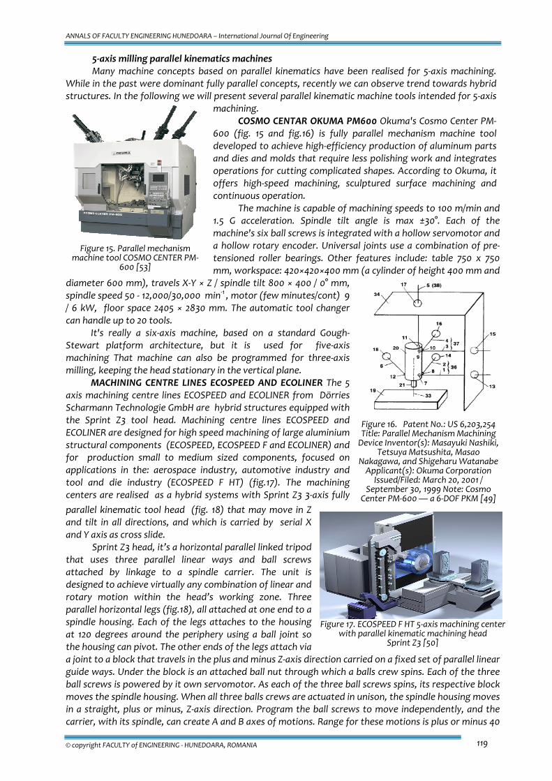
MACHINING CENTRE LINES ECOSPEED AND ECOLINER The 5 axis machining centre lines ECOSPEED and ECOLINER from Dörries Scharmann Technologie GmbH are hybrid structures equipped with the Sprint Z3 tool head. Machining centre lines ECOSPEED and ECOLINER are designed for high speed machining of large aluminium structural components (ECOSPEED, ECOSPEED F and ECOLINER) and for production small to medium sized components, focused on applications in the: aerospace industry, automotive industry and tool and die industry (ECOSPEED F HT) (fig.17). The machining centers are realised as a hybrid systems with Sprint Z3 3‐axis fully parallel kinematic tool head (fig. 18) that may move in Z and tilt in all directions, and which is carried by serial X and Y axis as cross slide.
Sprint Z3 head, it’s a horizontal parallel linked tripod that uses three parallel linear ways and ball screws attached by linkage to a spindle carrier. The unit is designed to achieve virtually any combination of linear and rotary motion within the head’s working zone. Three parallel horizontal legs (fig.18), all attached at one end to a spindle housing. Each of the legs attaches to the housing at 120 degrees around the periphery using a ball joint so the housing can pivot. The other ends of the legs attach via a joint to a block that travels in the plus and minus Z‐axis direction carried on a fixed set of parallel linear guide ways. Under the block is an attached ball nut through which a balls crew spins. Each of the three ball screws is powered by it own servomotor. As each of the three ball screws spins, its respective block moves the spindle housing. When all three balls crews are actuated in unison, the spindle housing moves in a straight, plus or minus, Z‐axis direction. Program the ball screws to move independently, and the carrier, with its spindle, can create A and B axes of motions. Range for these motions is plus or minus 40
Figure 15. Parallel mechanism
machine tool COSMO CENTER PM‐600 [53]
Figure 16. Patent No.: US 6,203,254 Title: Parallel Mechanism Machining Device Inventor(s): Masayuki Nashiki,
Tetsuya Matsushita, Masao Nakagawa, and Shigeharu Watanabe Applicant(s): Okuma Corporation
Issued/Filed: March 20, 2001 / September 30, 1999 Note: Cosmo
Center PM‐600 — a 6‐DOF PKM [49]
Figure 17. ECOSPEED F HT 5‐axis machining center
with parallel kinematic machining head Sprint Z3 [50]
ANNALS OF FACULTY ENGINEERING HUNEDOARA – International Journal Of Engineering
Tome X (Year 2012). Fascicule 2. ISSN 1584 – 2665 120
degrees about the A or B axes. The triangulation setup using parallel links gives the spindle high stiffness characteristics in both dynamic and static modes. Because of the reduced mass of the design, axial acceleration and deceleration for the Z3 head is 1G. Rapid feed rates are up to 50 m/min. The Z3 head’s maximal Z‐axis travel has been limited to 670 mm. This limited stroke gives the head rigidity to better machine thin wall sections in aluminium aerospace structural components.
The new Z3 head accommodates a motorized spindle with speed ranges of 7,500 to 40,000 available. Spindles up to 80 KW can be accommodated by the Z3 head design. Three different spindle brands are being offered for use in the Z3 to give users a choice of speed and torque combinations for various machining applications. Other characteristics of the Z3 head are: rotary acceleration ‐ 685°/s2 , rotary positioning velocity ‐ 80°/s.
More than 20 ECOSPEED’s machining centers are already in use in aircraft industry.
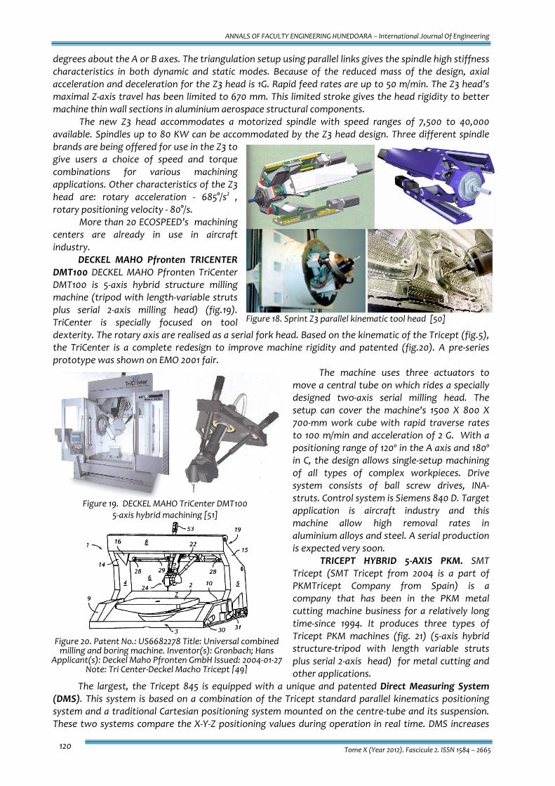
DECKEL MAHO Pfronten TRICENTER DMT100 DECKEL MAHO Pfronten TriCenter DMT100 is 5‐axis hybrid structure milling machine (tripod with length‐variable struts plus serial 2‐axis milling head) (fig.19). TriCenter is specially focused on tool dexterity. The rotary axis are realised as a serial fork head. Based on the kinematic of the Tricept (fig.5), the TriCenter is a complete redesign to improve machine rigidity and patented (fig.20). A pre‐series prototype was shown on EMO 2001 fair.
The machine uses three actuators to move a central tube on which rides a specially designed two‐axis serial milling head. The setup can cover the machine's 1500 X 800 X 700‐mm work cube with rapid traverse rates to 100 m/min and acceleration of 2 G. With a positioning range of 120º in the A axis and 180º in C, the design allows single‐setup machining of all types of complex workpieces. Drive system consists of ball screw drives, INA‐struts. Control system is Siemens 840 D. Target application is aircraft industry and this machine allow high removal rates in aluminium alloys and steel. A serial production is expected very soon.
TRICEPT HYBRID 5‐AXIS PKM. SMT Tricept (SMT Tricept from 2004 is a part of PKMTricept Company from Spain) is a company that has been in the PKM metal cutting machine business for a relatively long time‐since 1994. It produces three types of Tricept PKM machines (fig. 21) (5‐axis hybrid structure‐tripod with length variable struts plus serial 2‐axis head) for metal cutting and other applications.
The largest, the Tricept 845 is equipped with a unique and patented Direct Measuring System (DMS). This system is based on a combination of the Tricept standard parallel kinematics positioning system and a traditional Cartesian positioning system mounted on the centre‐tube and its suspension. These two systems compare the X‐Y‐Z positioning values during operation in real time. DMS increases
Figure 18. Sprint Z3 parallel kinematic tool head [50]
Figure 19. DECKEL MAHO TriCenter DMT100
5‐axis hybrid machining [51]
Figure 20. Patent No.: US6682278 Title: Universal combined milling and boring machine. Inventor(s): Gronbach; Hans
Applicant(s): Deckel Maho Pfronten GmbH Issued: 2004‐01‐27 Note: Tri Center‐Deckel Macho Tricept [49]
ANNALS OF FACULTY ENGINEERING HUNEDOARA – International Journal Of Engineering
© copyright FACULTY of ENGINEERING ‐ HUNEDOARA, ROMANIA 121
the stiffness and accuracy and it also compensates against the effects of cutting forces and temperature changes.
A Wrist Measuring System (WMS) controls the actual position of the rotary axes by means of external encoders mounted directly on the moving parts of the A and C axes.
A machine stand design based on a Modular Element System (MES) provides for flexibility to configure the machine to different angles (0°, 45°, 90°) and reconfiguration on site.
The Modular Setup System (MSS) offers easy and economical means of altering the setup when a customer wishes to change process/applications for the machine. A series of exchangeable modules are available.
Applications vary from light to heavier five axes machining of aluminum and plastics parts, model making, tool & die machining, etc.
Figure 21. Tricept hybrid 5‐axis PKM
In the following are given some of the technical characteristics for Tricept TMC 845: volumetric accuracy ±50µm; repeatability ±10µm; max feed rate 90 m/min; max acceleration 2G; Direct Measuring System (DMS): Heidenhain high resolution encoders; Wrist Measuring System (WMS): Heidenhain high resolution encoders; control system: Siemens SINUMERIK 840D; spindle 30/45 KW, 24,000 ‐ 30,000 min‐1,
HSK 63 ; tool changer: rack type,13 tools; umbrella type, 24 tools; floor space(machine) 3.7x3.6 m; floor space (incl. control cabinet and chip conveyor) 7.1x5.8 m; total machine weight 30,000 kg.
More than 200 machines are sold, mainly to automotive and aerospace customers such as GM, BMW, Peugeot, Citroën, Boeing, Airbus, Volvo, Scania, SAAB Aerospace, Renault, Volkswagen, Alstom.
Non milling applications of parallel kinematics machines Recently parallel kinematics machines start to focus on other applications than milling, for
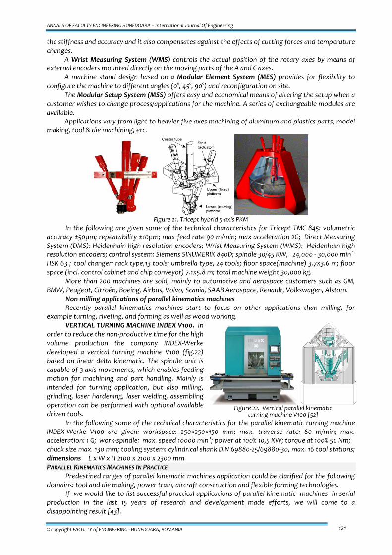
example turning, riveting, and forming as well as wood working. VERTICAL TURNING MACHINE INDEX V100. In
order to reduce the non‐productive time for the high volume production the company INDEX‐Werke developed a vertical turning machine V100 (fig.22) based on linear delta kinematic. The spindle unit is capable of 3‐axis movements, which enables feeding motion for machining and part handling. Mainly is intended for turning application, but also milling, grinding, laser hardening, laser welding, assembling operation can be performed with optional available driven tools.
In the following some of the technical characteristics for the parallel kinematic turning machine INDEX‐Werke V100 are given: workspace: 250×250×150 mm; max. traverse rate: 60 m/min; max. acceleration: 1 G; work‐spindle: max. speed 10000 min‐1; power at 100% 10,5 KW; torque at 100% 50 Nm; chuck size max. 130 mm; tooling system: cylindrical shank DIN 69880‐25/69880‐30, max. 16 tool stations; dimensions L x W x H 2100 x 2100 x 2300 mm. PARALLEL KINEMATICS MACHINES IN PRACTICE
Predestined ranges of parallel kinematic machines application could be clarified for the following domains: tool and die making, power train, aircraft construction and flexible forming technologies.
If we would like to list successful practical applications of parallel kinematic machines in serial production in the last 15 years of research and development made efforts, we will come to a disappointing result [43].
Figure 22. Vertical parallel kinematic
turning machine V100 [52]

ANNALS OF FACULTY ENGINEERING HUNEDOARA – International Journal Of Engineering
Tome X (Year 2012). Fascicule 2. ISSN 1584 – 2665 122
Actually we could list 3 successful examples: � Tricept for deburring, milling and drilling (not too precise) of simple automotive parts, � ECOSPEED Machining centers for milling and drilling of alloy integral aerospace parts � Index V100 for turning and additional operations of turned parts.
After we analyze the benefits of each concept, we can find out 3 common reasons for success: � the right design concept adapted to the specific application, � in application to use the benefit of the specific PKM advantage(s), � to avoid the disadvantages, using consequently their strong points according the rule “only as good
as necessary”. Here the examples:
� High speed/low precision deburring, milling and drilling‐Tricept is sufficient; � solving the current bottleneck in 5‐axis high speed machining, the limited dynamics of a rotary tool
axis and the required compensation movements of the linear axis‐ Special Z3 Sprint parallel kinematic head implemented in ECOSPEED Machining centers;
� a vertical turning machine based on linear Delta principle with a limited working area for (high) precision turning application and an expanded working area for others (not high stiffness required applications) as measuring, handling load and unload‐ INDEX V 100 is optimal.
The common issues for the above mentioned 3 machine concepts are: limited universality, devoted to specific technological applications (technology and workpiece) and high performance machining as a consequence.
For the future more successful introduction of PKM in practice on two main targets should be focused: � characteristics of the parallel kinematic machines should be comparable with serial kinematic
machines and � parallel kinematic machines should not complicate operator’s life more than serial kinematic
machines. CONCLUSION AND RECOMMENDATIONS FOR FUTURE
Parallel kinematic machine tools after more than 15 years intensive research and development efforts, slowly but surely, entering the commercial market in different industrial applications enables benefits to the customers.
The parallel kinematic machine tools which are successful on the market have been designed to solve some specific problem (bottleneck) in application of serial machine tools, and to enable most effective use of conceptual advantages of PKM, and in the same time avoiding the conceptual disadvantages by conceptual approach or advanced technological solutions.
If we compare about 15 years research in parallel kinematic machine tools and more than 200 years experience and research to reach the current level of serial machine tools, it is easy to conclude that solving the problems in PKM will need time.
In order to obtain wider practical application of parallel kinematic machine tools the further intensive research and development is necessary.
We will mention here several open problems and needs: � in the field of design and performance prediction of parallel kinematic machine tools it is very
important to be created effective tools for optimal topological and dimensional synthesis and overall design of the PKM towards special application in order to be possible the most effective use of conceptual advantages of the parallel mechanisms.
� parallel kinematic machine tools consist of components like joints and struts which have key importance of the overall performance characteristics of the machine. Further improvement and refinement of components is needed.
For example, creating joints with high and linear stiffness, high damping and wide swivelling angles; development of components fitted to special kinematic structure; lightweight construction of assemblies subjected to torque, etc. � Accuracy and controller. Analysis have shown that more of the 70% errors on the fabricated parts
are induced by controller, CAD/CAM system is responsible of approximately 20% of the errors, and the parallel mechanism (if optimally designed) less than 10% [26]. Hence research should be focused mostly on the controller. The hardware of the controller should support: the possibility of using

ANNALS OF FACULTY ENGINEERING HUNEDOARA – International Journal Of Engineering
© copyright FACULTY of ENGINEERING ‐ HUNEDOARA, ROMANIA 123
appropriate control laws capable to deal with inherent non‐ linearities of parallel kinematic machine tools; parallel computation (that will drastically improve the sampling time); creating automated calibration algorithms and routines to be realised high position accuracy; generating interfaces for the compensation models (elastic and thermal deformations in the controller; active compensation of the disturbance forces, etc.
� Maintenance issues, like machine calibration and evaluation of geometric accuracy should be practically, shop‐floor, developed and oriented. This will enable the machine users to handle these issues according their previous experience with classical serial machine tools.
ACKNOWLEDGMENTS This research was done at the Department of Machine Tools and Automation, TU Hamburg‐Harburg, Germany, financed by DFG (Deutsche Forschungsgemeinschaft). REFERENCES [1.] ANGELES J., 2002, The Qualitative Synthesis of Parallel Manipulators, Proceedings of the WORKSHOP on
Fundamental Issues and Future Research Directions for Parallel Mechanisms and Manipulators October 3–4, 2002, Quebec City, Quebec, Canada pp.160‐168
[2.] ANNACONDIA, E., APILE, E., DOTTA, A., BOËR, C. R., 2002, An Experience in Design and Development of Joints for Parallel Kinematics Machines, The 3rd Chemnitz Parallel Kinematics Seminar PKS 2002, Chemnitz, Germany, pp.243‐261
[3.] BONEV I. , 2001, Delta Parallel Robot — the Story of Success, www.parallemic.org/Reviews/Review002.html [4.] BONEV I. , 2003, What is Going on With Parallel Robots www.roboticsonline.com/public/articles/ [5.] BROGARDH T., 2002, PKM Research ‐ Important Issues, as seen from a Product Development Perspective at
ABB Robotics, Proceedings of the WORKSHOP on Fundamental Issues and Future Research Directions for Parallel Mechanisms and Manipulators October 3–4, 2002, Quebec City, Quebec, Canada, pp.68‐82
[6.] CECCARELLI M., CARBONE G. AND OTTAVIANO E., 2005, Multi criteria optimum design of manipulators, BULLETIN of the POLISH ACADEMY of SCIENCES, TECHNICAL SCIENCES, Volume 53, Issue 1, 2005, pp 9 ‐ 18
[7.] DENKENA, B.; GRENDEL, H.; HOLZ, C., 2004, Model Based Feedforward and State Control of the Parallel Kinematics PaLiDA. The 4 Chemnitz Parallel Kinematics Seminar PKS2004, Chemnitz, Germany, April 20‐21, 2004, pp.185‐202
[8.] DÜRSCHMIED, F., HESTERMANN, J.‐O., 2002, Achieving Technical and Economic Potential with INA Components, The 3rd Chemnitz Parallel Kinematics Seminar PKS 2002, Chemnitz, Germany, pp.263‐275
[9.] FANG Y., TSAI L.‐W., 2002, Structure Synthesis of a Class of 4‐DoF and 5‐DoF Parallel Manipulators with Identical Limb Structures, THE INTERNATIONAL JOURNAL OF ROBOTICS RESEARCH , September 2002, pp.799‐810
[10.] GOUGH V. E., WITEHALL S. G., 1962, Universal Tire Test Machine, Proceedings of the 9th International Automobile Technical Congress FISITA, London (UK), ImechE (pp. 117 – 137) 1962.
[11.] GROTJAHN, M.; ABDELLATIF, H.; HEIMANN, B., 2004, Path Accuracy Improvement of Parallel Kinematic Structures by the Identification of Friction and Rigid Body Dynamics, The 4 Chemnitz Parallel Kinematics Seminar PKS2004, Chemnitz, Germany, April 20‐21, 2004, pp.257‐275
[12.] HAO F., MERLET J.‐P., 2005, Multi‐criteria optimal design of parallel manipulators based on interval analysis, Mechanism and Machine Theory 40 (2005) 157–171
[13.] HENNES, N., 2002, ECOSPEED, An Inniovative Machinery Concept for High‐Performance 5‐Axis‐Machining of Large Strutural Comonents in Aircraft Engineering, The 3rd Chemnitz Parallel Kinematics Seminar PKS 2002, Chemnitz, Germany, pp.763‐774
[14.] HENNES, N.; STAIMER, D., 2004, Application of PKM in Aerospace Manufacturing – High Performance Machining Centers ECOSPEED, ECOSPEED‐F and ECOLINER , The 4th Chemnitz Parallel Kinematics Seminar PKS 2004, Chemnitz, Germany pp. 557‐568
[15.] HERTEL, A., 2002, Requiremants for Parallel Kinematics for Powertrain Manufacturing in the Automotive Industry, The 3rd Chemnitz Parallel Kinematics Seminar PKS 2002, Chemnitz, Germany, pp.753‐762
[16.] HONEGGER M., CODOUREY A., BURDET E., 1997, Adaptive Control of the Hexaglide, a 6 dof Parallel Manipulator, IEEE International Conference on Robotics and Automation, Albuquerque, USA, April 1997
[17.] HONEGGER M., 1998, Nonlinear adaptive control of a 6‐DOF. parallel manipulator, MOVIC '98, Zurich, Switzerland,. August 25‐28, vol. 3, pp. 961‐966, 1998
[18.] HSU W.‐Y., CHEN J.‐S., 2004, Error analysis and auto‐calibration for a Cartesian‐guided tripod machine tool, Int J Adv Manuf Technol (2004) 24: pp. 899–909
[19.] KRUTH J.‐P., VANHERCK P.,. VAN DEN BERGH C, 2001, Compensation of Static and Transient Thermal Errors on CMMs, Annals of CIRP, 50/1/2001, pp.377‐384
[20.] LILLA, A., 2002, Quicker Success with Hybrid Kinematics »ECOSPEED«, The 3rd Chemnitz Parallel Kinematics Seminar PKS 2002, Chemnitz, Germany, pp.775‐784
[21.] LOU Y. ET AL., 2004, A general approach for optimal kinematic design of parallel manipulators, Proceedings of the IEEE Int. Conf. on Robotics and Automation, pp. 3659‐3664, New Orleans, 28‐30 April 2004
[22.] LOU Y.J., LIU G.F., AND LI Z.X., 2005, A General Approach for Optimal Design of Parallel Manipulators, submited to IEEE TRANSACTIONS ON AUTOMATION SCIENCE AND ENGINEERING, VOL. X, NO. X, XX 2005
[23.] MAIER, V., 2000, Metav 2000: Durchbruch bei den Parallelkinematik‐Maschinen VDI‐Z 9/10, 2000, pp.30‐32 [24.] MARTÍNEZ, L.; COLLADO, V., 2004, Calibration of a Hybrid Serial/Parallel 5‐Axes Milling Machine Using a
Double Ball Bar Probe, The 4 Chemnitz Parallel Kinematics Seminar PKS2004, Chemnitz, Germany, April 20‐21, 2004, pp.137‐150
[25.] MENG J., LIU G., LI Z., 2005, A Geometric Theory for Synthesis and Analysis of Sub‐6 DoF Parallel Manipulators, International Conference on Robotics and Automation, April18‐2005, Barcelona, Spain

ANNALS OF FACULTY ENGINEERING HUNEDOARA – International Journal Of Engineering
Tome X (Year 2012). Fascicule 2. ISSN 1584 – 2665 124
[26.] MERLET J. P., 2000, Parallel robots, Kluwer, 2000 [27.] MERLET J.‐P., 2002, An initiative for the kinematics study of parallel manipulators, Proceedings of the
WORKSHOP on Fundamental Issues and Future Research Directions for Parallel Mechanisms and Manipulators, October 3–4, 2002, Quebec City, Quebec, Canada, pp.1‐9
[28.] NEUGEBAUER, R.; KRABBES, M.; KRETSCHMAR, W.; SCHÖNITZ, J., 2002, Improvement of the Calibration Accuracy by a New Measurement Process, The 3rd Chemnitz Parallel Kinematics Seminar PKS 2002, Chemnitz, Germany, pp.443‐454
[29.] NEUMANN, K. E., 2002, Tricept Applications, The 3rd Chemnitz Parallel Kinematics Seminar PKS 2002, Chemnitz, Germany, pp.547‐551
[30.] NEUMANN, K. E., 2004, Next Generation Tricept –A True Revolution in Parallel Kinematics, The 4th Chemnitz Parallel Kinematics Seminar PKS 2004, Chemnitz, Germany, pp.591‐594
[31.] OTTAVIANO E. AND CECCARELLI M., 2001, Optimal Design of CaPaMan (Cassino Parallel Manipulator) With Prescribed Position and Orientation Workspace, Proceedings of the IEEE 9th Mediterranean Conference on Control and Automation, June 27‐29, 2001, Dubrovnik, Croatia
[32.] OTTAVIANO E. AND CECCARELLI M., 2002, Optimum Design of Parallel Manipulators for Workspace and Singularity Performances, Proceedings of the WORKSHOP on Fundamental Issues and Future Research Directions for Parallel Mechanisms and Manipulators October 3–4, 2002, Quebec City, Quebec, Canada, pp.98‐105
[33.] PATEL A.J., EHMANN K.F., 1997, Volumetric error analysis of a Stewart platform based machine tool, Annals of CIRP, 46/1/1997, pp. 287‐290
[34.] PIERROT F., DAUCHEZ P., AND FOURNIER A., 1991, Hexa: a fast six‐ fully parallel robot, Proceedings of ICAR conference, 1991, pp. 1159‐1163.
[35.] PRITSCHOW G., WURST K.‐H., 1997, Systematic design of hexapods and other parallel link systems, Annals of CIRP, 46/1/1997, pp.291‐295
[36.] PRITSCHOW, G., EPPLER, C., GARBER, T., 2002, Influence of the Dynamic Stiffness on the Accuracy of PKM, 3rd Chemnitz Parallel Kinematics Seminar, PKS 2002, Chemnitz, 2002, pp.313‐333.
[37.] PRITSCHOW G., EPPLER C., LEHNER W. ‐D., 2003, Ferraris Sensor‐The Key for Advanced Dynamic Drives, Annals of the CIRP Vol. 52/1/2003, pp.289‐292.
[38.] REHSTEINER F., NEUGEBAUER R., SPIEWAK S., WIELAND F., 1999, Putting parallel kinematics machines (PKM) to productive work, Annals of CIRP, 48/1/1999, p. 345‐350.
[39.] SCHNYDER, M.; GIOVANOLA, J.; CLAVEL, R.; THURNEYSEN, M.; JEANNERAT, D., 2004, Spherical Joints with 3 and 4 Degrees of Freedom for 5‐Axis Parallel Kinematics Machine Tool, The 4 Chemnitz Parallel Kinematics Seminar PKS2004, Chemnitz, Germany, April 20‐21, 2004, pp.487‐502
[40.] SCHOPPE, E.; PÖNISCH, A.; MAIER, V.; PUCHTLER, T.; IHLENFELDT, S., 2002, Tripod Machine SKM 400 Design, Callibration and Practical Application, The 3rd Chemnitz Parallel Kinematics Seminar PKS 2002, Chemnitz, Germany, pp.579‐594
[41.] STEWART, D., 1965, A Platform with Six Degrees of Freedom, Proc. Inst. Mech. Eng. London, Vol 180, 1965, pp. 371‐386.
[42.] TLUSTY J., ZIEGERT J., RIDGEWAY S., 1999, Fundamental comparison of the use of serial and parallel kinematics for machine tools authors, Annals of CIRP, 48/1/1999, pp. 351‐356
[43.] TREIB, T., 2002, Parallel Kinematic Machines in Practice, The 3rd Chemnitz Parallel Kinematics Seminar PKS 2002, Chemnitz, Germany, pp.63‐66
[44.] TSAI L. W., 1999, Robot Analysis: The Mechanics of Serial and Parallel Manipulators, New York: John Wiley & Sons, Inc., 1999.
[45.] WECK M., STAIMER D., 2000, On the Accuracy of Parallel Machine Tools: Design, Compensation and Calibration, 2nd Chemnitz Parallel Kinematics Seminar, PKS 2000, Chemnitz, 2000, pp.73‐83
[46.] WECK M., STAIMER D., 2002, Parallel Kinematic Machines Tools ‐ Current State and Future Potentials, Annals of CIRP, 51/2/2002, p.671‐683
[47.] WEIKERT, S.; KNAPP, W., 2002, Application of the Grid‐Bar Device on the Hexaglide, The 3rd Chemnitz Parallel Kinematics Seminar PKS 2002, Chemnitz, Germany, pp.295‐310
[48.] WURST K.‐H., DUBOIS L., 1998, Das Maschinenkonzept LINAPOD, Umdruck zum Seminar "Hexapod, Linapod, Dyna‐M" am 11./12. März 1998, Aachen
[49.] www.delphion.com [50.] www.ds‐technologie.de [51.] www.ifw.uni‐hannover.de/robotool [52.] www.index‐werke.de/en/index/produkte/verticalline/v100 [53.] www.okuma‐overseas.com/product/PM_600.HTM [54.] www.parallemic.org [55.] www.pkm‐news.de
ANNALS OF FACULTY ENGINEERING HUNEDOARA
– INTERNATIONAL JOURNAL OF ENGINEERING
copyright © UNIVERSITY POLITEHNICA TIMISOARA, FACULTY OF ENGINEERING HUNEDOARA,
5, REVOLUTIEI, 331128, HUNEDOARA, ROMANIA http://annals.fih.upt.ro