Components for parallel kinematics - schaeffler.com · 2 Components for parallel kinematics Ball...
12
Market Information MAI 66 Components for parallel kinematics Series GLK, GLK 2, GLK 3 and GLAE Parallel kinematic components consist of a number of parallel, longitudinally adjustable mechanical struts that are arranged between the machine frame and the main spindle (see Fig.1). Joints at the ends of the struts provide a pivotal connection bet- ween the frame and the spindle. Mechanical in-feed of the tool head is accomplished by means of electronically controlled, varying strut lengths. Switching the struts in parallel will normally move all of the assemblies present simultaneously. Five degrees of freedom per strut are normally required for parallel kinematics, and these are provided by ball and universal joints. Advantages of parallel kinematics Parallel kinematics differ from serial kinematics in the three- dimensional framework of their struts. Due to its Cartesian structure, the serial design is susceptible to tensile and compressive forces as well as torsional and bending forces. The joints and struts in three-dimensional structures are subject solely to tensile and compressive forces (see Fig. 2). In contrast to machines incorporating traditional serial kinematics, machines are now available that are not only fast and extremely rigid, but also operate free of bending and torsional stresses. Parallel kinematics with INA components: ■ are very rigid since – all forces from the joints and struts are always supported simultaneously – the kinematics of the joint transforms forces into tensile and compressive forces – low lateral forces from linear guidance systems are supported by the struts ■ enable high accelerations because components are smaller and thus have lower masses ■ operate very accurately since the total error quotient always refers to the struts rather than the sum of all axis errors (X, Y and Z axes), as is the case with serial kinematics (see Fig. 3) ■ simplify overall machine mechanics and reduce the number of parts since struts and joints are supplied as complete units ■ provide high mobility during the machining process since the low mass of the machine allows it to be moved toward the workpiece ■ make machining more flexible since even complex processes can be completed in a single sequence ■ are particularly suitable for the guidance and control of tool heads, for robots and for the machining of highly complex workpieces. Figure 1 · Parallel kinematics – schematic view Figure 2 · Dynamic effect in serial ➀ and parallel ➁ frames Figure 3 · Accuracy for serial ➀ and parallel ➁ kinematics 107 366 1 2 107 367 3 (Z) 1 (X) 4 (a) 5 (b) total error = 1+2+3+4+5 2 (X,Y,Z,a,b,c) 2 (Y) 1 2 107 368
-
Upload
nguyentuong -
Category
Documents
-
view
225 -
download
0
Transcript of Components for parallel kinematics - schaeffler.com · 2 Components for parallel kinematics Ball...

Market Information MAI 66
Components for parallel kinematicsSeries GLK, GLK 2, GLK 3 and GLAE
Parallel kinematic components consist of a number of parallel, longitudinally adjustable mechanical struts that are arranged between the machine frame and the main spindle (see Fig.1). Joints at the ends of the struts provide a pivotal connection bet-ween the frame and the spindle. Mechanical in-feed of the tool head is accomplished by means of electronically controlled, varying strut lengths. Switching the struts in parallel will normally move all of the assemblies present simultaneously.Five degrees of freedom per strut are normally required for parallel kinematics, and these are provided by ball and universal joints.
Advantages of parallel kinematicsParallel kinematics differ from serial kinematics in the three-dimensional framework of their struts. Due to its Cartesian structure, the serial design is susceptible to tensile and compressive forces as well as torsional and bending forces. The joints and struts in three-dimensional structures are subject solely to tensile and compressive forces (see Fig. 2). In contrast to machines incorporating traditional serial kinematics, machines are now available that are not only fast and extremely rigid, but also operate free of bending and torsional stresses. Parallel kinematics with INA components:� are very rigid since
– all forces from the joints and struts are always supported simultaneously
– the kinematics of the joint transforms forces into tensile and compressive forces
– low lateral forces from linear guidance systems are supported by the struts
� enable high accelerations because components are smaller and thus have lower masses
� operate very accurately since the total error quotient always refers to the struts rather than the sum of all axis errors (X, Y and Z axes), as is the case with serial kinematics (see Fig. 3)
� simplify overall machine mechanics and reduce the number of parts since struts and joints are supplied as complete units
� provide high mobility during the machining process since the low mass of the machine allows it to be moved toward the workpiece
� make machining more flexible since even complex processes can be completed in a single sequence
� are particularly suitable for the guidance and control of tool heads, for robots and for the machining of highly complex workpieces.
Figure 1 · Parallel kinematics – schematic view
Figure 2 · Dynamic effect in serial ➀ and parallel ➁ frames
Figure 3 · Accuracy for serial ➀ and parallel ➁ kinematics
107
366
1 2
107
367
3 (Z)
1 (X)4 (a)
5 (b)
total error = 1+2+3+4+5 2 (X,Y,Z,a,b,c)
2 (Y)
1 2
107
368

2
Components for parallel kinematicsBall joints
with three degrees of freedom
Universal joints
with two or three degrees of freedom
Features
Ball and universal jointsBall and universal joints for parallel kinematics:� have two or three degrees of freedom
(depending on the design)� transform torsional and bending forces into tensile and
compressive forces by means of joint kinematics� are very rigid and have a high load carrying capacity� are preloaded and thus clearance-free� operate smoothly and free of stick-slip� have pivot angles adapted to the design� have a defined joint intersecting point� are sealed� are lubricated with a special grease and can be
relubricated� are Corrotect®-plated.
Ball joints� consist of:
– a ball pin with external threads, a ball cup with centering seat, a hemisphere, a hollow spherical seal carrier and a locknut
– a large number of small balls. This ensures low Hertzian pressure between the ball cup, the hemisphere, the ball pin and the rolling element.
– a lubrication adapter for polyamide tube DIN 73 378� have three degrees of freedom� have pivot angles from �20º or to �30º (optional).
Universal joints� consist of:
– a yoke with centering seat, a cross, preloaded and sealed radial and thrust needle roller bearings, and a locknut with lock washer
� have either two or three degrees of freedom– third degree of freedom by means of a combination
radial/thrust bearing in the head of the cross� have maximum pivot angles
– up to �45º in axis I– up to �90º in axis II– up to 360º in axis III.
Ball joint
˚C
� hemisphere with ground outer raceway for seals, screw-mounted with ball cup
� hollow spherical seal carrier screw-mounted to ball pin with locknut
� full complement set of balls� rolling element raceways hardened � suitable for temperatures from –30 ºC to +120 ºC
�Universal joint
˚C
� GLK 2 with two degrees of freedom, GLK 3 with three degrees of freedom
� cross in yoke supported with radial/thrust bearings� combination radial/thrust bearing for third degree of
freedom, axially located with locknut� locknut with lock washer for tight fit with strut� suitable for temperatures from –30 ºC to +120 ºC
GLK
107
357
GLK 2GLK 3
107
359

3
Telescopic struts
Features
Telescopic strutsTelescopic struts for parallel kinematics:� consist of:
– a sliding tube and a stanchion, a drive spindle with nut, a DKLFA four-row angular contact thrust ball bearing and four KUVS linear recirculating ball bearing units
� are equipped with INA ball and universal joints– the type of joint depends on the application and/or
customer requirements� are equipped with a ball screw drive or a planetary roller
screw, depending on the rigidity required– screw pitch depends on the feed rate and/or customer
requirements– the DKLFA four-row angular contact thrust ball bearing
permits high spindle speeds with maximum rigidity� are suitable for high feed rates� move very accurately and smoothly and are free of
stick-slip� are clearance-free in all directions due to the torsionally
rigid linear guidance systems and the ground raceways in the outer surface of the sliding tube
� have a low mass due to the design of the components� are Corrotect®-plated� can be supplied either with or without cardan suspension
– the suspension can be supplied with U-joint bearings or with angular contact thrust ball bearings for heavy loads
� are manufactured with sliding-tube diameters of 50 mm and 70 mm– other dimensions are possible on request
� are supplied with various strokes– shortest stroke = 400 mm, longest stroke = 900 mm
� can be matched to customer specifications in terms of stroke, rigidity and reactive forces
� allow compact designs with fewer components in conjunction with ball and universal joints.
Telescopic strut
˚C
� internal threads or flange connection in the sliding tube to support ball or universal joints
� sliding tube with ground raceways for KUVS linear recirculating ball bearing units
� spindle nut located in sliding tube and secured against rotation
� suited for temperatures ranging from –30 ºC to +120 ºC
GLAE
107
358

4
Load ratings for ball and universal joints
Maximum load capacityThe maximum load carrying capacity Pmax of ball joints depends on the:� size of the joint� direction of the load (tensile/compressive load). Pmax can be found in Fig. 1.
Figure 1 · Maximum load capacity Pmax
max
imum
load
car
ryin
g ca
paci
tyPmax
KN
7
6
3,53
F-232 386.1 (compression)F-232 386.1 (tension)
F-232 956 (compression)F-232 956 (tension)
pivot angles up to 30˚
107
380

5
Static load ratings for universal jointsThe static load ratings C0 depend on the:� type of joint� pivot angle �.Only the pivot angle � affects static load rating C0. Pivot angles � and � have no effect on the static load rating.
Static load safety factor S0 must be �4.INA should be consulted in the case of a deviating load safety factor.
Static load ratings C0 can be found in Fig. 2 and Fig. 3 for each type of joint.Joint types:� F-232 098.1 and F-232 099.1 (Fig. 2)� F-232 919 and F-232 920 (Fig. 2)� F-233 323 and F-233 324 (Fig. 3).
Figure 2 · Static load ratings C0 with respect to pivot angle �
Figure 3 · Static load ratings C0 with respect to pivot angle �
F-232 098.1 / F-232 099.1
F-232 919.1 / F-232 920.1
100
90KN
80
70
60
81
5051
40
30
20
10
65,7
55,8
load
car
ryin
g ca
paci
ty
0
10˚ 20˚ 30˚ 40˚ 45˚ 50˚
pivot angle axis �
C
107
381
F-233 323 / F-233 324
20
KN15,5
15
12,5
10
5
load
car
ryin
g ca
paci
ty
011
10˚ 20˚ 30˚ 40˚ 45˚ 50˚
pivot angle axis �
C
107
382

6
Ball jointwith three degrees of freedom
Series GLK
1) Easy-connect cartridge for polyamide tube DIN 73 378 Ø4�0.75 with connecting thread M10�1, min. 6 mm deep.2) Measured and logged.3) 2 times on circumference.4) 6 times on circumference.5) See diagrams on page 4 for load ratings.
GLK
Dimensions table · Dimensions in mm
Designation F-Number Weight Degrees of freedom
Pivot angle Dimensions
kg°� � �
H h1 h22) h3 h4 h5 h6
GLK F-232 956 2.3 3 20�20�360 144 35 35 35 20 19 10
GLK F-232 386.1 4.5 3 20�20�360 185 40 50 44 30 21 10
b
5
4
3
3 3)
4)
DM
h
h
h
2h
6h
1h
d
3d
MD
SA
a
c
2
M
d
1d
H
107
353

7
Load ratings Rigidity Appropriate INA strutD d1
h6
d2 d3 Ma Mb Mc SA C0
kN
Cs tensile
N/�m
70 40 32 6 M20�1.5 M17�1 M40�1.5 1) 5) 280 Ø 50
90 55 45 6 M25�1.5 M25�1.5 M56�2 1) 5) 350 Ø 70

8
Universal jointwith two degrees of freedom
Series GLK 2
with three degrees of freedom
Series GLK 3
F-233 324 with two degrees of freedom
2
1
4
5
Ddd
h
h
107
355
1) Measured and logged.2) See diagrams on page 5 for load ratings.
F-233 323 with three degrees of freedom
Dimensions table · Dimensions in mm
Designation F-Number Weight Degrees offreedom
Pivot angle Dimensions
kg°� � �
L l1 l2 B b1 H h11) h2
GLK 3 F-233 323 3 3 90�45�360 125 107 – 50 28 126 10 50
GLK 2 F-233 324 3 2 90�45 125 107 – 50 28 115 10 50
GLK 3 F-232 919 7 3 90�45�360 150 135 80 85 70 155 45 28
GLK 2 F-232 920 7 2 90�45 150 135 80 85 70 155 45 28
GLK 3 F-232 098.1 14 3 90�45�360 200 180 120 110 90 215 60 40
GLK 2 F-232 099.1 14 2 90�45 200 180 120 110 90 215 60 40
centering connection
centering connection
cylindrical roller Ø 12�18included separately
1
Dd
d
M
h
h
h
2
5
4
3
h2
h1
a
max. 45˚
max
. 90˚
�
5
Ø12
l
L
H6
1
1M
�H
b
B1
107
354
9
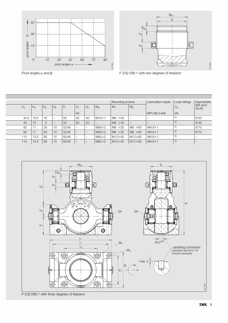
Pivot angles � and � F-232 099.1 with two degrees of freedom
pivot angles �
pivo
t ang
les
45˚
45˚
30˚
30˚
15˚
15˚0˚ 60˚ 75˚ 90˚
�
107
361
M
h
h
h
DA
6
5
4
107
365
F-232 098.1 with three degrees of freedom
Mounting screws Lubrication nipple Load ratings Appropriate INA strutGLAEh3 h4 h5 h6 D d1
h6
d2 Ma M1 M2
NIP DIN 3 405
C0
kN
34,5 15.5 16 – 50 30 40 M15�1 M8 �40 – – 2) Ø 50
40 10 5 – 50 30 40 – M8 �40 – – 2) Ø 50
82 11 29 10 52 h6 – – M56�2 M8 �30 M8 �60 AM 8�1 2) Ø 70
82 11 29 10 52 h6 – – M56�2 M8 �30 M8 �60 AM 8�1 2) Ø 70
115 13.5 38 15 60 h6 – – M65�2 M12�40 M12�80 AM 8�1 2) –
115 13.5 38 15 60 h6 – – M65�2 M12�40 M12�80 AM 8�1 2) –
34
5
6
2
hh
hh
h
1h
Ma
max. 45˚ max. 45˚
�
SA SA
ll1 1
1
2
2
LM
M
B
b
��
max. 2
centering connectioncylindrical roller Ø12�18included separately
H6Ø12
H
D
107
356

10
Telescopic strutsSeries GLAE
1) Will depend on the surrounding structure and must be determined by the customer.2) Depending on type of joint.
GLAE
Dimensions table · Dimensions in mm
Designation Diameter of sliding tube
Dimensions
ØD1 D2 d3 d4 MA L1 L2 Stroke
GLAE 50 50 75 1) 1) 2) 1) 1) 1)
GLAE 70 70 120 1) 1) 2) 1) 1) 1)
M
DD
1
2
A
1
4
3
LL 2
2
L
d
dD
107
360

11
Application example
3D Waterjet cuttingHexapod handling structure
107
362

Sac
h-N
r. 00
5-29
9-46
2/M
AI 6
6 U
S-D
070
01
· P
rinte
d in
Ger
man
y
INA Wälzlager Schaeffler oHG91072 Herzogenaurach (Germany)Telephone (+49 9132) 82-0Fax (+49 9132) 82-49 50www.ina.com


![Effects of Sensitive Electrical Stimulation-Based ... · significant improvement in gait kinematics and angular excursion of lower limb joints. Similarly, Kleiner et al. [24] applied](https://static.fdocuments.in/doc/165x107/5fc35ad71d12864ca02889b2/effects-of-sensitive-electrical-stimulation-based-significant-improvement-in.jpg)