ENG3640 Microcomputer Interfacing Week #11 Memory Interfacing.
Upload
winter-owensCategory
view
58download
2description
Parallel Interfacing
Chapter 7
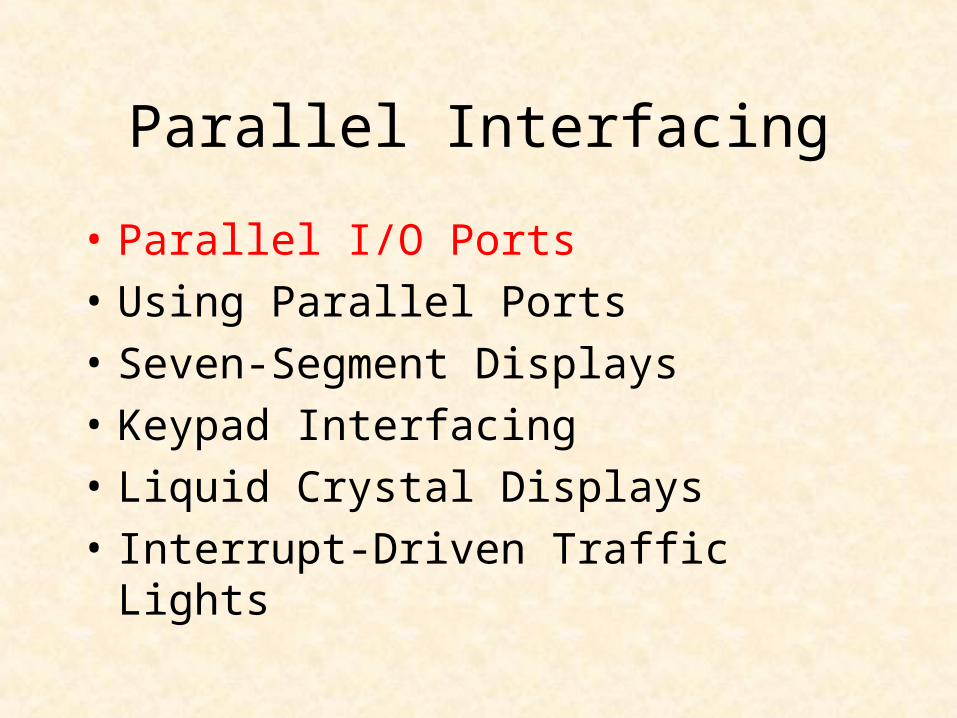
Parallel Interfacing
• Parallel I/O Ports
• Using Parallel Ports
• Seven-Segment Displays
• Keypad Interfacing
• Liquid Crystal Displays
• Interrupt-Driven Traffic Lights
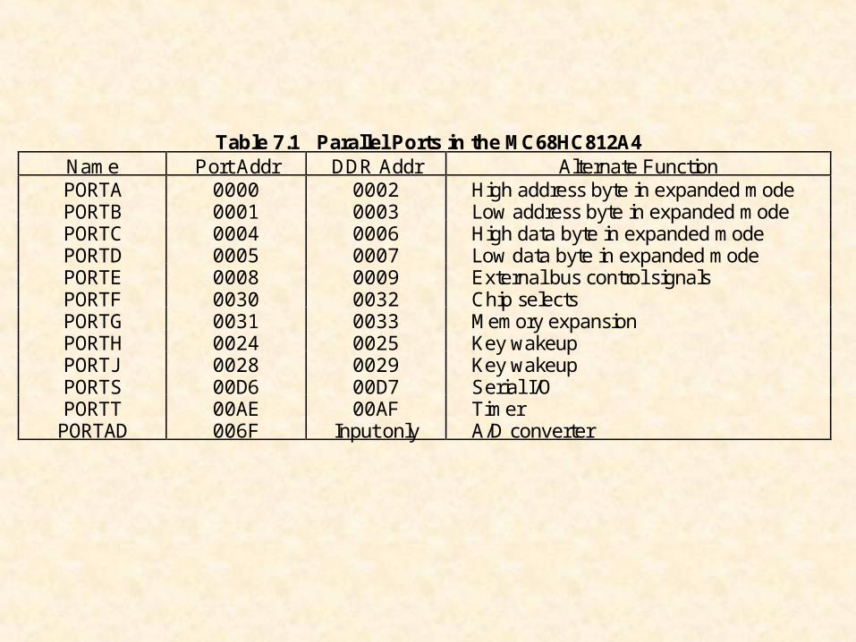
Table 7.1 Parallel Ports in the MC68HC812A4Name Port Addr DDR Addr Alternate FunctionPORTA 0000 0002 High address byte in expanded modePORTB 0001 0003 Low address byte in expanded modePORTC 0004 0006 High data byte in expanded modePORTD 0005 0007 Low data byte in expanded modePORTE 0008 0009 External bus control signalsPORTF 0030 0032 Chip selectsPORTG 0031 0033 Memory expansionPORTH 0024 0025 Key wakeupPORTJ 0028 0029 Key wakeupPORTS 00D6 00D7 Serial I/OPORTT 00AE 00AF TimerPORTAD 006F Input only A/D converter
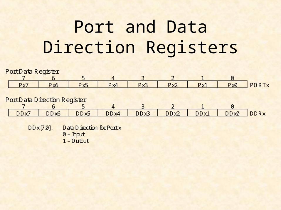
Port and Data Direction Registers
Port Data Register7 6 5 4 3 2 1 0
Px7 Px6 Px5 Px4 Px3 Px2 Px1 Px0 PORTx
Port Data Direction Register7 6 5 4 3 2 1 0
DDx7 DDx6 DDx5 DDx4 DDx3 DDx2 DDx1 DDx0 DDRx
DDx[7:0]: Data Direction for Port x0 – Input1 – Output
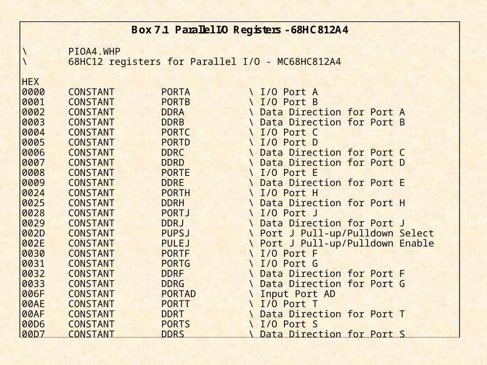
Box 7.1 Parallel I/O Registers - 68HC812A4
\ PIOA4.WHP\ 68HC12 registers for Parallel I/O - MC68HC812A4
HEX0000 CONSTANT PORTA \ I/O Port A0001 CONSTANT PORTB \ I/O Port B0002 CONSTANT DDRA \ Data Direction for Port A0003 CONSTANT DDRB \ Data Direction for Port B0004 CONSTANT PORTC \ I/O Port C0005 CONSTANT PORTD \ I/O Port D0006 CONSTANT DDRC \ Data Direction for Port C0007 CONSTANT DDRD \ Data Direction for Port D0008 CONSTANT PORTE \ I/O Port E0009 CONSTANT DDRE \ Data Direction for Port E0024 CONSTANT PORTH \ I/O Port H0025 CONSTANT DDRH \ Data Direction for Port H0028 CONSTANT PORTJ \ I/O Port J0029 CONSTANT DDRJ \ Data Direction for Port J002D CONSTANT PUPSJ \ Port J Pull-up/Pulldown Select002E CONSTANT PULEJ \ Port J Pull-up/Pulldown Enable0030 CONSTANT PORTF \ I/O Port F0031 CONSTANT PORTG \ I/O Port G0032 CONSTANT DDRF \ Data Direction for Port F0033 CONSTANT DDRG \ Data Direction for Port G006F CONSTANT PORTAD \ Input Port AD00AE CONSTANT PORTT \ I/O Port T00AF CONSTANT DDRT \ Data Direction for Port T00D6 CONSTANT PORTS \ I/O Port S00D7 CONSTANT DDRS \ Data Direction for Port S
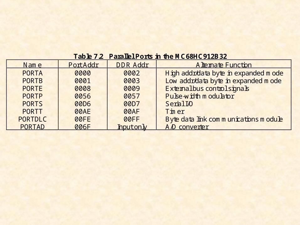
Table 7.2 Parallel Ports in the MC68HC912B32Name Port Addr DDR Addr Alternate FunctionPORTA 0000 0002 High addr/data byte in expanded modePORTB 0001 0003 Low addr/data byte in expanded modePORTE 0008 0009 External bus control signalsPORTP 0056 0057 Pulse-width modulatorPORTS 00D6 00D7 Serial I/OPORTT 00AE 00AF TimerPORTDLC 00FE 00FF Byte data link communications modulePORTAD 006F Input only A/D converter
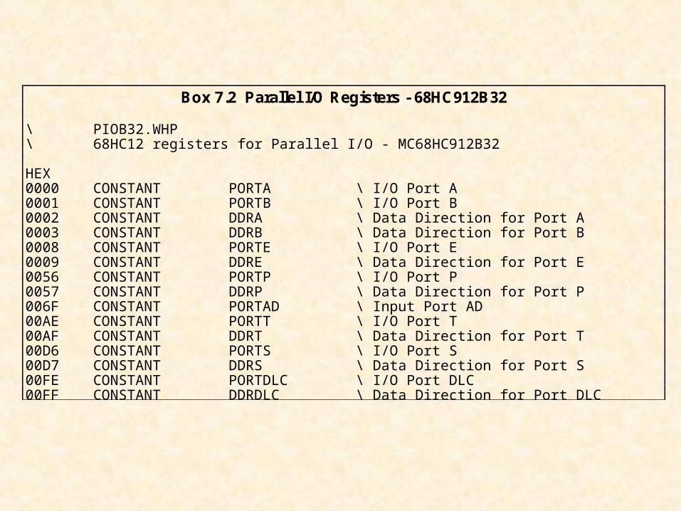
Box 7.2 Parallel I/O Registers - 68HC912B32
\ PIOB32.WHP\ 68HC12 registers for Parallel I/O - MC68HC912B32
HEX0000 CONSTANT PORTA \ I/O Port A0001 CONSTANT PORTB \ I/O Port B0002 CONSTANT DDRA \ Data Direction for Port A0003 CONSTANT DDRB \ Data Direction for Port B0008 CONSTANT PORTE \ I/O Port E0009 CONSTANT DDRE \ Data Direction for Port E0056 CONSTANT PORTP \ I/O Port P0057 CONSTANT DDRP \ Data Direction for Port P006F CONSTANT PORTAD \ Input Port AD00AE CONSTANT PORTT \ I/O Port T00AF CONSTANT DDRT \ Data Direction for Port T00D6 CONSTANT PORTS \ I/O Port S00D7 CONSTANT DDRS \ Data Direction for Port S00FE CONSTANT PORTDLC \ I/O Port DLC00FF CONSTANT DDRDLC \ Data Direction for Port DLC
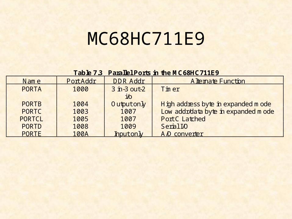
MC68HC711E9
Table 7.3 Parallel Ports in the MC68HC711E9Name Port Addr DDR Addr Alternate FunctionPORTA 1000 3 in-3 out-2
i/oTimer
PORTB 1004 Output only High address byte in expanded modePORTC 1003 1007 Low addr/data byte in expanded modePORTCL 1005 1007 Port C LatchedPORTD 1008 1009 Serial I/OPORTE 100A Input only A/D converter
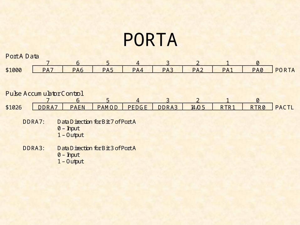
Port A Data7 6 5 4 3 2 1 0
$1000 PA7 PA6 PA5 PA4 PA3 PA2 PA1 PA0 PORTA
Pulse Accumulator Control7 6 5 4 3 2 1 0
$1026 DDRA7 PAEN PAMOD PEDGE DDRA3 I4/O5 RTR1 RTR0 PACTL
DDRA7: Data Direction for Bit 7 of Port A0 – Input1 – Output
DDRA3: Data Direction for Bit 3 of Port A0 – Input1 – Output
PORTA
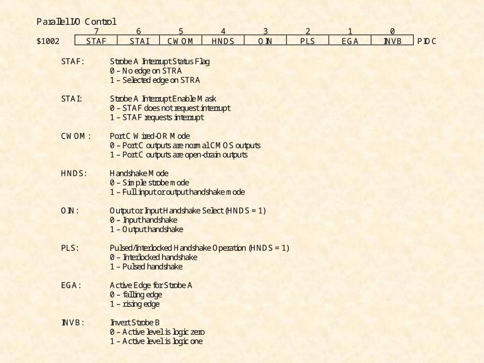
Parallel I/O Control7 6 5 4 3 2 1 0
$1002 STAF STAI CWOM HNDS OIN PLS EGA INVB PIOC
STAF: Strobe A Interrupt Status Flag0 – No edge on STRA1 – Selected edge on STRA
STAI: Strobe A Interrupt Enable Mask0 – STAF does not request interrupt1 – STAF requests interrupt
CWOM: Port C Wired-OR Mode0 – Port C outputs are normal CMOS outputs1 – Port C outputs are open-drain outputs
HNDS: Handshake Mode0 – Simple strobe mode1 – Full input or output handshake mode
OIN: Output or Input Handshake Select (HNDS = 1)0 – Input handshake1 – Output handshake
PLS: Pulsed/Interlocked Handshake Operation (HNDS = 1)0 – Interlocked handshake1 – Pulsed handshake
EGA: Active Edge for Strobe A0 – falling edge1 – rising edge
INVB: Invert Strobe B0 – Active level is logic zero1 – Active level is logic one
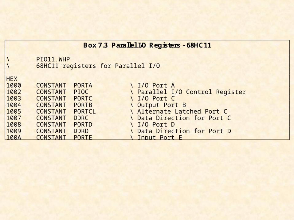
Box 7.3 Parallel I/O Registers - 68HC11
\ PIO11.WHP\ 68HC11 registers for Parallel I/O
HEX1000 CONSTANT PORTA \ I/O Port A1002 CONSTANT PIOC \ Parallel I/O Control Register1003 CONSTANT PORTC \ I/O Port C1004 CONSTANT PORTB \ Output Port B1005 CONSTANT PORTCL \ Alternate Latched Port C1007 CONSTANT DDRC \ Data Direction for Port C1008 CONSTANT PORTD \ I/O Port D1009 CONSTANT DDRD \ Data Direction for Port D100A CONSTANT PORTE \ Input Port E
Parallel Interfacing
• Parallel I/O Ports
• Using Parallel Ports
• Seven-Segment Displays
• Keypad Interfacing
• Liquid Crystal Displays
• Interrupt-Driven Traffic Lights
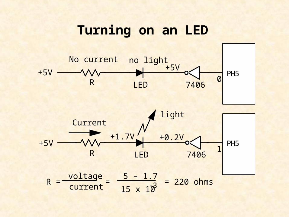
+5VR LED
PH5
+5VR LED
0
1
+5V
+0.2V+1.7V
No current
Current light
no light
R = voltagecurrent
=5 – 1.7
15 x 10-3 = 220 ohms
PH5
7406
7406
Turning on an LED
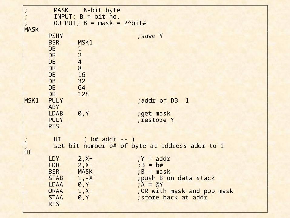
; MASK 8-bit byte; INPUT: B = bit no.; OUTPUT; B = mask = 2^bit#MASK
PSHY ;save YBSR MSK1DB 1DB 2DB 4DB 8DB 16DB 32DB 64DB 128
MSK1 PULY ;addr of DB 1ABYLDAB 0,Y ;get maskPULY ;restore YRTS
; HI ( b# addr -- ); set bit number b# of byte at address addr to 1HI
LDY 2,X+ ;Y = addrLDD 2,X+ ;B = b#BSR MASK ;B = maskSTAB 1,-X ;push B on data stackLDAA 0,Y ;A = @YORAA 1,X+ ;OR with mask and pop maskSTAA 0,Y ;store back at addrRTS
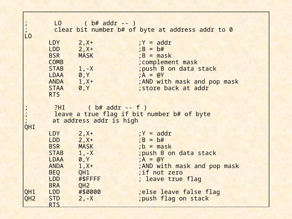
; LO ( b# addr -- ); clear bit number b# of byte at address addr to 0LO
LDY 2,X+ ;Y = addrLDD 2,X+ ;B = b#BSR MASK ;B = maskCOMB ;complement maskSTAB 1,-X ;push B on data stackLDAA 0,Y ;A = @YANDA 1,X+ ;AND with mask and pop maskSTAA 0,Y ;store back at addrRTS
; ?HI ( b# addr -- f ); leave a true flag if bit number b# of byte; at address addr is highQHI
LDY 2,X+ ;Y = addrLDD 2,X+ ;B = b#BSR MASK ;b = maskSTAB 1,-X ;push B on data stackLDAA 0,Y ;A = @YANDA 1,X+ ;AND with mask and pop maskBEQ QH1 ;if not zeroLDD #$FFFF ; leave true flagBRA QH2
QH1 LDD #$0000 ;else leave false flagQH2 STD 2,-X ;push flag on stack
RTS
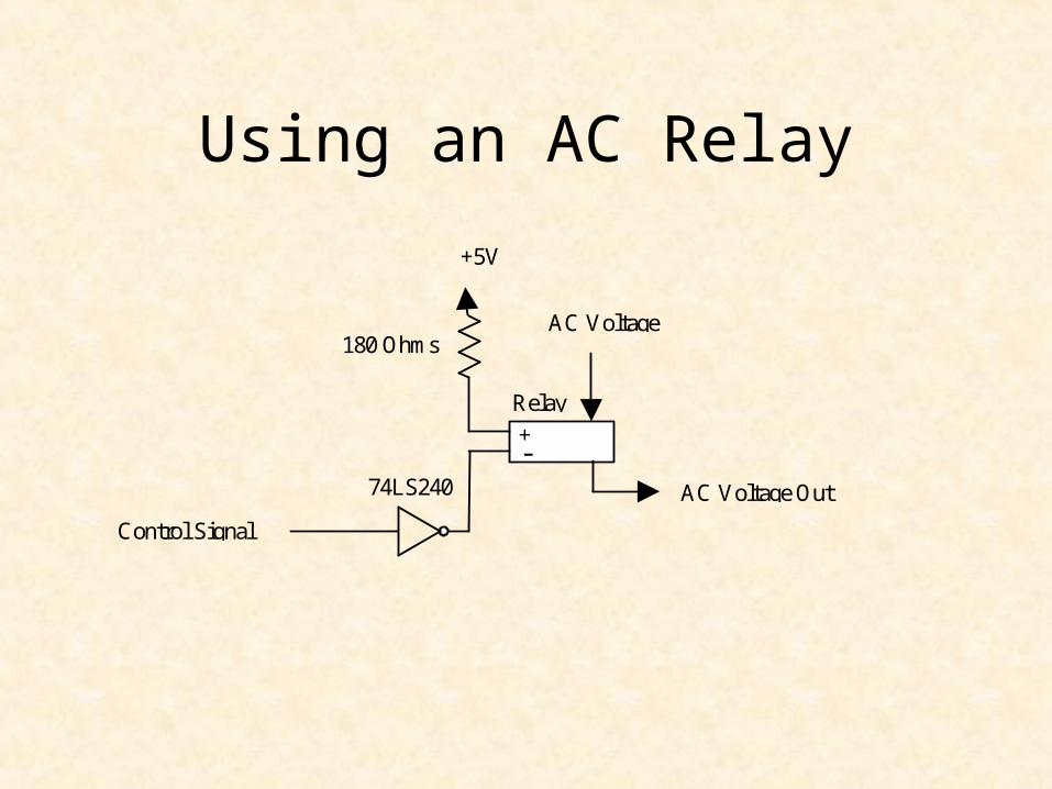
Using an AC Relay
74LS240
+ -
Relay
+5V
180 OhmsAC Voltage
AC Voltage Out
Control Signal
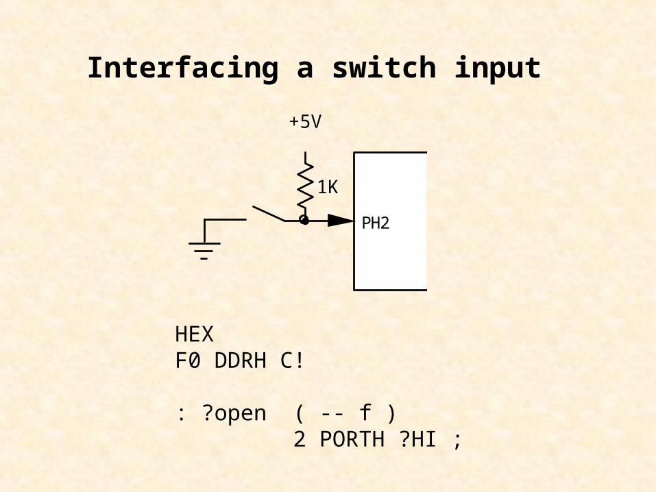
1K
PH2
+5V
Interfacing a switch input
HEXF0 DDRH C!
: ?open ( -- f ) 2 PORTH ?HI ;
Parallel Interfacing
• Parallel I/O Ports
• Using Parallel Ports
• Seven-Segment Displays
• Keypad Interfacing
• Liquid Crystal Displays
• Interrupt-Driven Traffic Lights
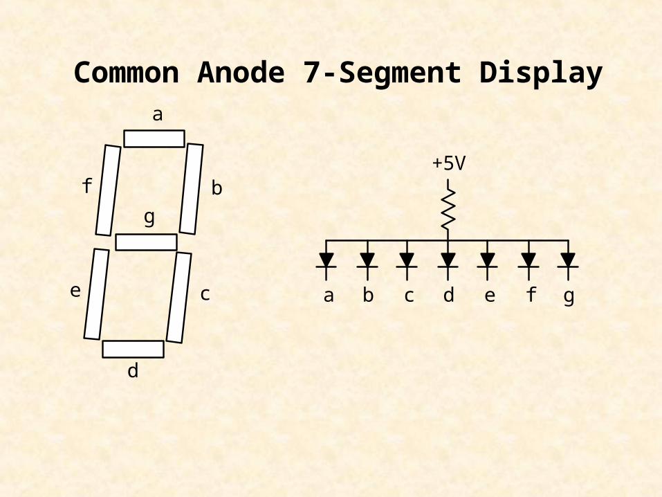
a
b
c
d
e
f
g
a b c d e f g
+5V
Common Anode 7-Segment Display
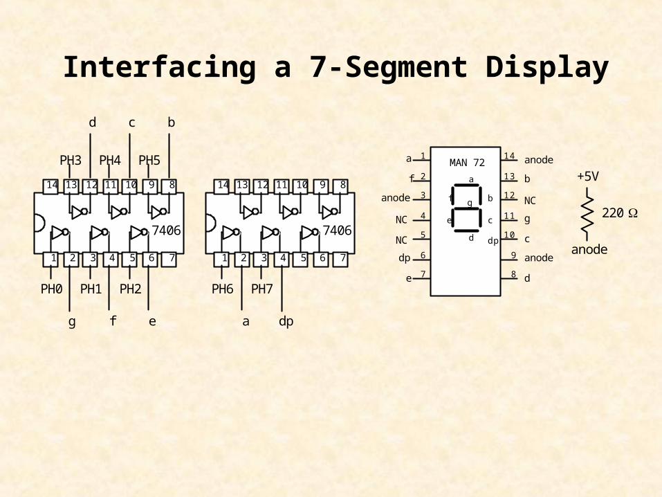
Interfacing a 7-Segment Display
1 2 3 4 5 6 7
891011121314
1 2 3 4 5 6 7
891011121314
1
2
3
4
5
6
7
9
10
11
12
13
14
8
MAN 72a
b
c
de
f
g
dp
anode
anode
anode
NC
NC
NC
a
b
c
d
e
f g
dp
PH0 PH1 PH2
PH3 PH4 PH5
PH6 PH7
dpa
bcd
efg
anode
+5V
220 7406 7406
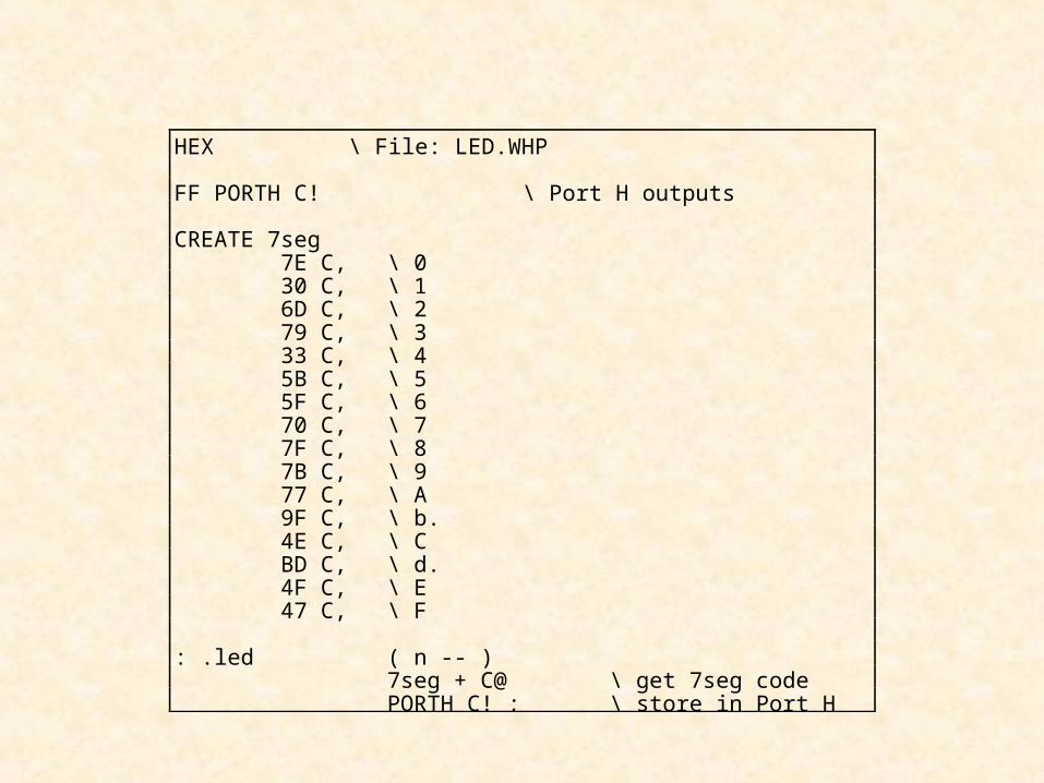
HEX \ File: LED.WHP
FF PORTH C! \ Port H outputs
CREATE 7seg 7E C, \ 0 30 C, \ 1 6D C, \ 2 79 C, \ 3 33 C, \ 4 5B C, \ 5 5F C, \ 6 70 C, \ 7 7F C, \ 8 7B C, \ 9 77 C, \ A 9F C, \ b. 4E C, \ C BD C, \ d. 4F C, \ E 47 C, \ F
: .led ( n -- ) 7seg + C@ \ get 7seg code PORTH C! ; \ store in Port H
1
2
3
4
5
6
7
8 9
10
11
12
13
14
15
16
GND
e
f
g
h+i
A
B
LE
C
D
j
a
b
c
d
VDD
MC14495-1
1
2
3
4
5 10
9
8
7
6
ANODE-a
ANODE-b
ANODE-f
ANODE-g
ANODE-dp
ANODE-c
COMMON CATHODE
ANODE-d
ANODE-e
COMMON CATHODEa
bc
d
e f
g
dp
MAN 6780
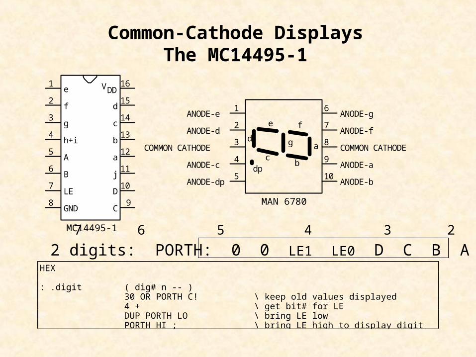
Common-Cathode DisplaysThe MC14495-1
HEX
: .digit ( dig# n -- ) 30 OR PORTH C! \ keep old values displayed 4 + \ get bit# for LE DUP PORTH LO \ bring LE low PORTH HI ; \ bring LE high to display digit
2 digits: PORTH: 0 0 LE1 LE0 D C B A7 6 5 4 3 2 1 0
Parallel Interfacing
• Parallel I/O Ports
• Using Parallel Ports
• Seven-Segment Displays
• Keypad Interfacing
• Liquid Crystal Displays
• Interrupt-Driven Traffic Lights
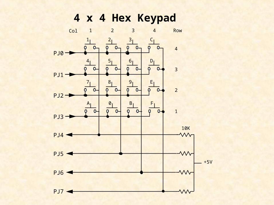
A 0 B F
7 8 9
4
E
5 6 D
1 2 3 C
+5V
PJ0
PJ1
PJ2
PJ3
PJ4
PJ5
PJ6
PJ7
Col 1 2 3 4 Row
4
3
2
1
10K
4 x 4 Hex Keypad
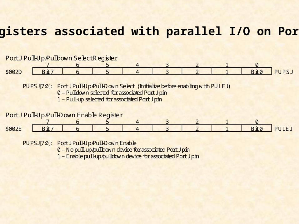
Port J Pull-Up/Pulldown Select Register7 6 5 4 3 2 1 0
$002D Bit 7 6 5 4 3 2 1 Bit 0 PUPSJ
PUPSJ[7:0]: Port J Pull-Up/Pull-Down Select (Initialize before enabling with PULEJ)0 – Pulldown selected for associated Port J pin1 – Pull-up selected for associated Port J pin
Port J Pull-Up/Pull-Down Enable Register7 6 5 4 3 2 1 0
$002E Bit 7 6 5 4 3 2 1 Bit 0 PULEJ
PUPSJ[7:0]: Port J Pull-Up/Pull-Down Enable0 – No pull-up/pulldown device for associated Port J pin1 – Enable pull-up/pulldown device for associated Port J pin
Registers associated with parallel I/O on Port J
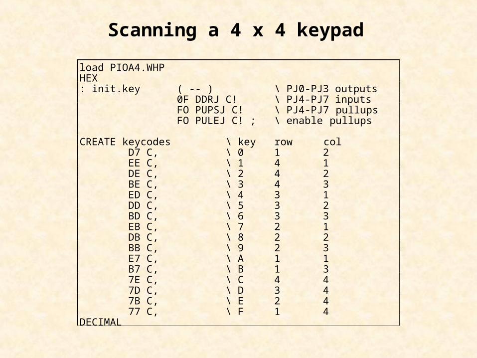
load PIOA4.WHPHEX: init.key ( -- ) \ PJ0-PJ3 outputs 0F DDRJ C! \ PJ4-PJ7 inputs FO PUPSJ C! \ PJ4-PJ7 pullups FO PULEJ C! ; \ enable pullups
CREATE keycodes \ key row col D7 C, \ 0 1 2 EE C, \ 1 4 1 DE C, \ 2 4 2 BE C, \ 3 4 3 ED C, \ 4 3 1 DD C, \ 5 3 2 BD C, \ 6 3 3 EB C, \ 7 2 1 DB C, \ 8 2 2 BB C, \ 9 2 3 E7 C, \ A 1 1 B7 C, \ B 1 3 7E C, \ C 4 4 7D C, \ D 3 4 7B C, \ E 2 4 77 C, \ F 1 4DECIMAL
Scanning a 4 x 4 keypad
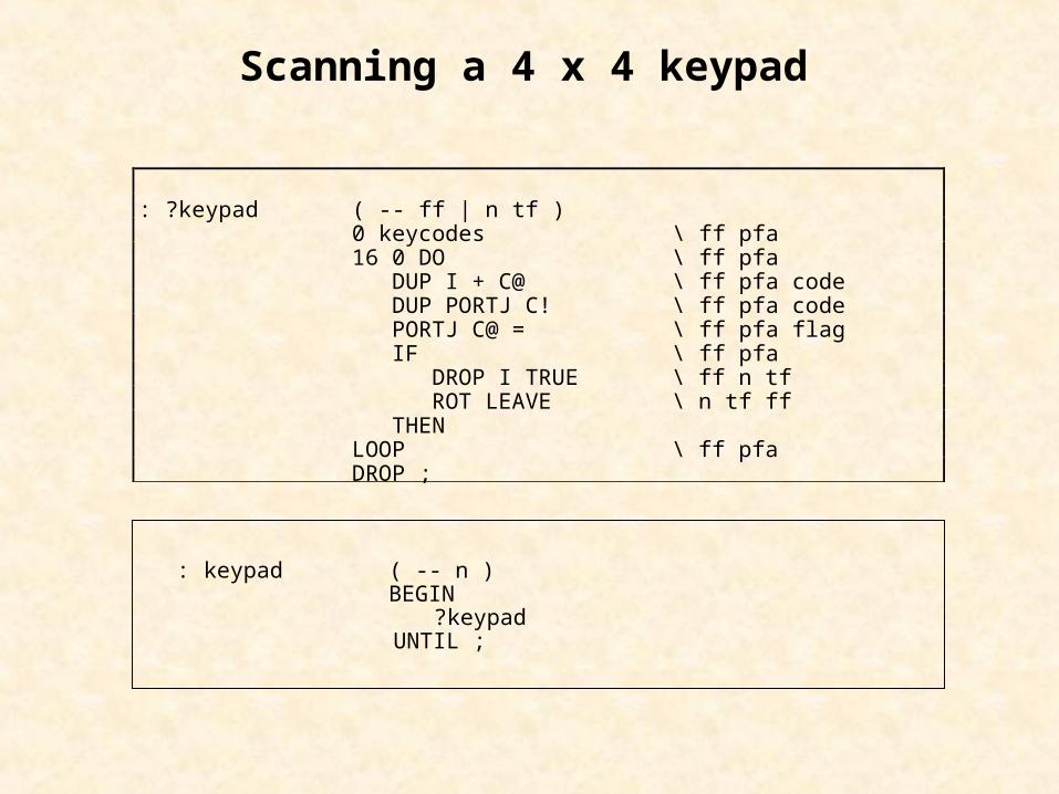
Scanning a 4 x 4 keypad
: ?keypad ( -- ff | n tf ) 0 keycodes \ ff pfa 16 0 DO \ ff pfa DUP I + C@ \ ff pfa code DUP PORTJ C! \ ff pfa code PORTJ C@ = \ ff pfa flag IF \ ff pfa DROP I TRUE \ ff n tf ROT LEAVE \ n tf ff THEN LOOP \ ff pfa DROP ;
: keypad ( -- n ) BEGIN ?keypad UNTIL ;
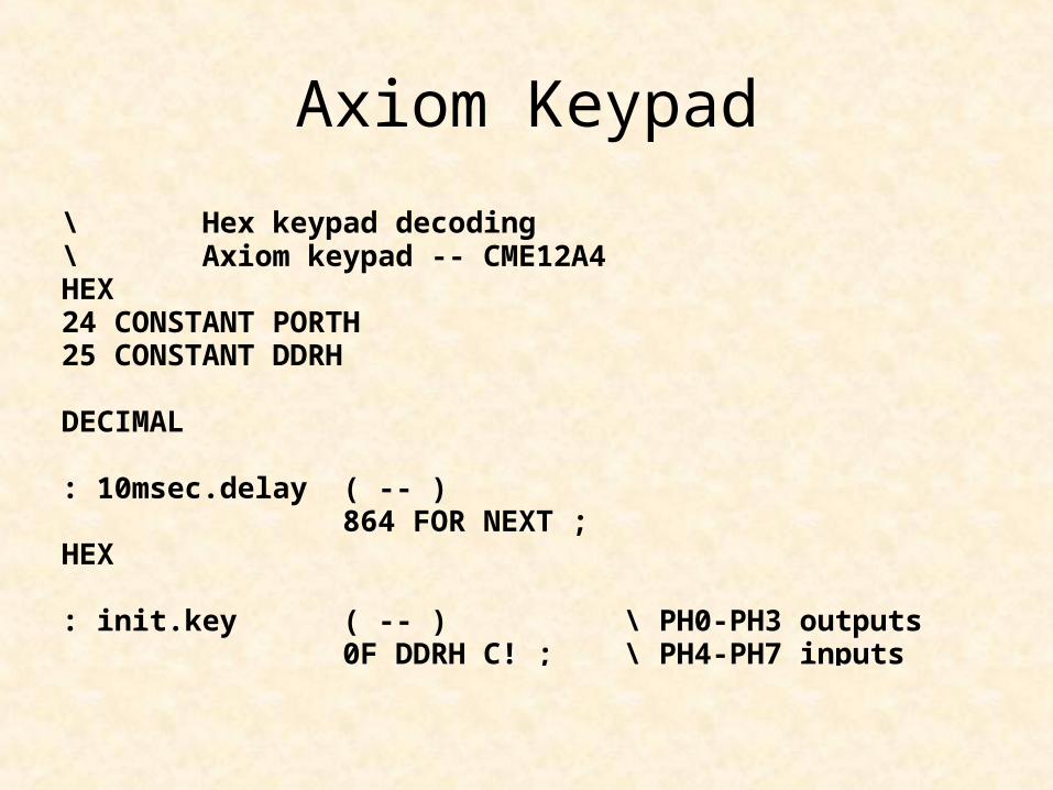
Axiom Keypad
\ Hex keypad decoding\ Axiom keypad -- CME12A4HEX24 CONSTANT PORTH25 CONSTANT DDRH
DECIMAL
: 10msec.delay ( -- ) 864 FOR NEXT ;HEX
: init.key ( -- ) \ PH0-PH3 outputs 0F DDRH C! ; \ PH4-PH7 inputs
* 0 # D
7 8 9
4
C
5 6 B
1 2 3 A
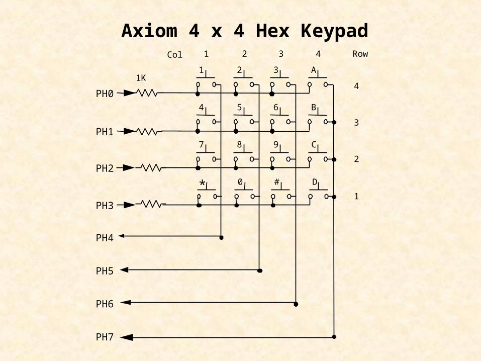
PH0
PH1
PH2
PH3
PH4
PH5
PH6
PH7
Col 1 2 3 4 Row
4
3
2
1
1K
Axiom 4 x 4 Hex Keypad
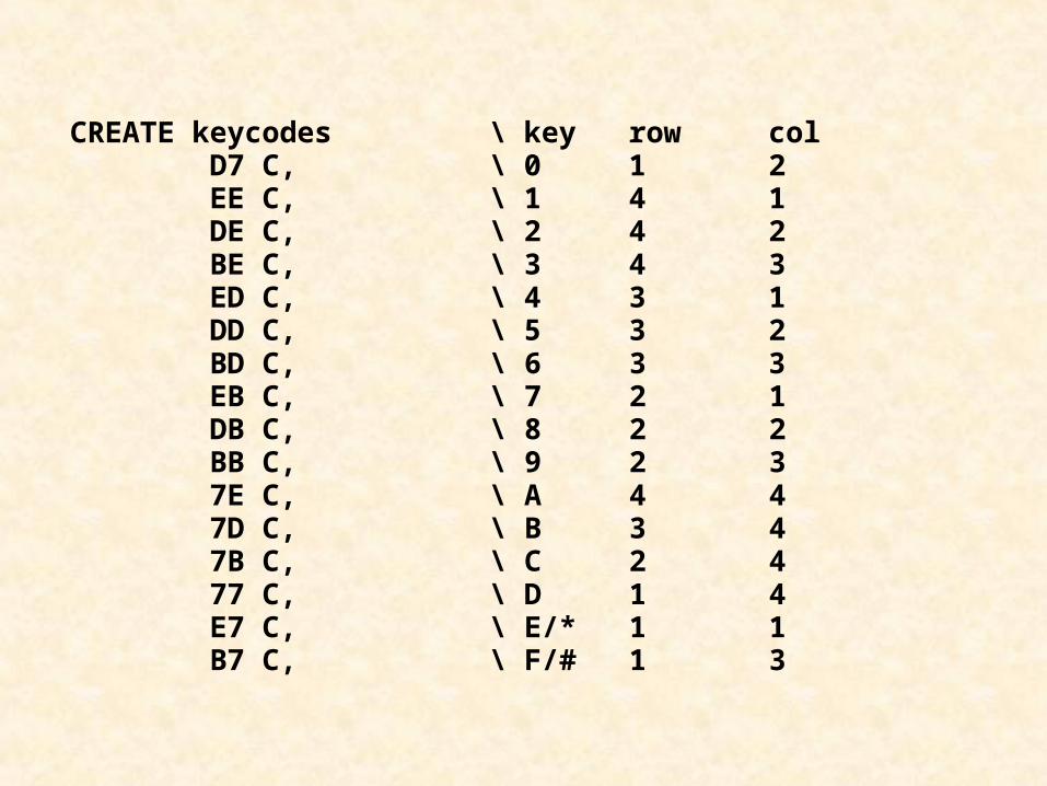
CREATE keycodes \ key row col D7 C, \ 0 1 2 EE C, \ 1 4 1 DE C, \ 2 4 2 BE C, \ 3 4 3 ED C, \ 4 3 1 DD C, \ 5 3 2 BD C, \ 6 3 3 EB C, \ 7 2 1 DB C, \ 8 2 2 BB C, \ 9 2 3 7E C, \ A 4 4 7D C, \ B 3 4 7B C, \ C 2 4 77 C, \ D 1 4 E7 C, \ E/* 1 1 B7 C, \ F/# 1 3
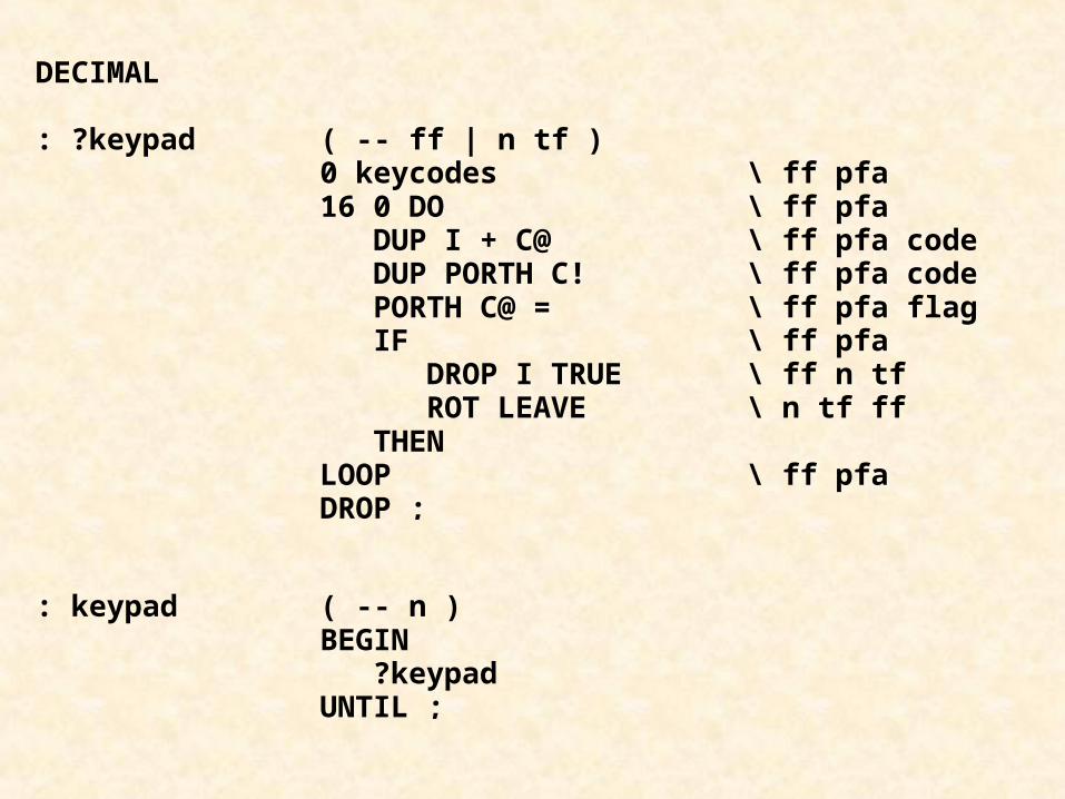
DECIMAL
: ?keypad ( -- ff | n tf ) 0 keycodes \ ff pfa 16 0 DO \ ff pfa DUP I + C@ \ ff pfa code DUP PORTH C! \ ff pfa code PORTH C@ = \ ff pfa flag IF \ ff pfa DROP I TRUE \ ff n tf ROT LEAVE \ n tf ff THEN LOOP \ ff pfa DROP ;
: keypad ( -- n ) BEGIN ?keypad UNTIL ;
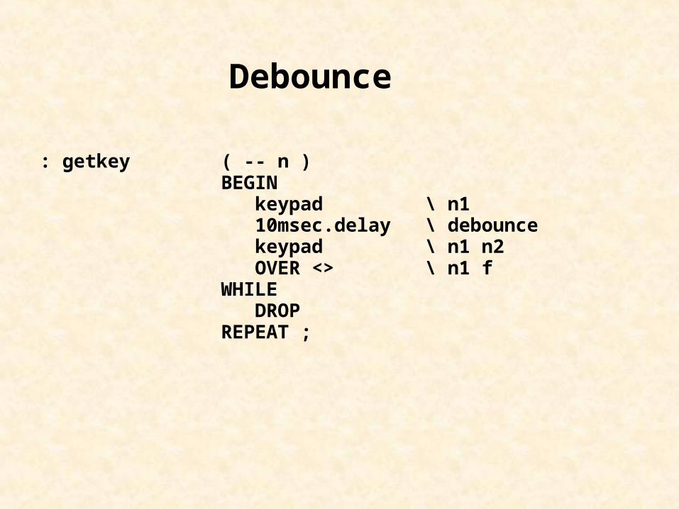
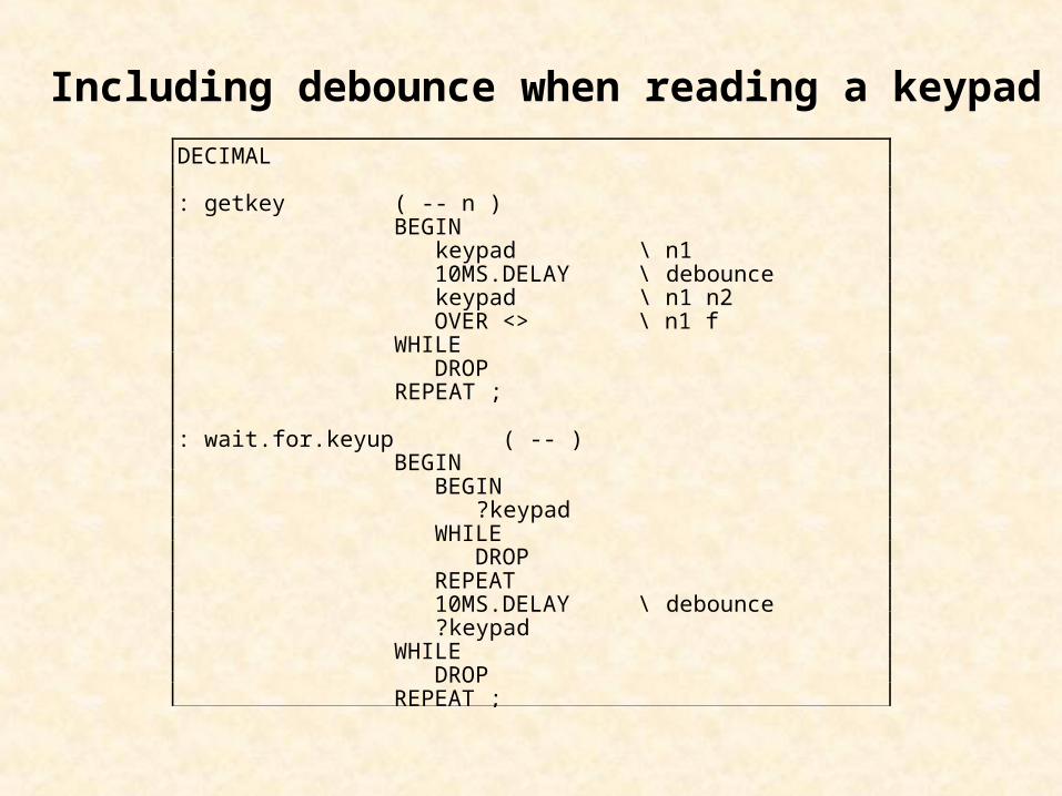
: getkey ( -- n ) BEGIN keypad \ n1 10msec.delay \ debounce keypad \ n1 n2 OVER <> \ n1 f WHILE DROP REPEAT ;
Debounce
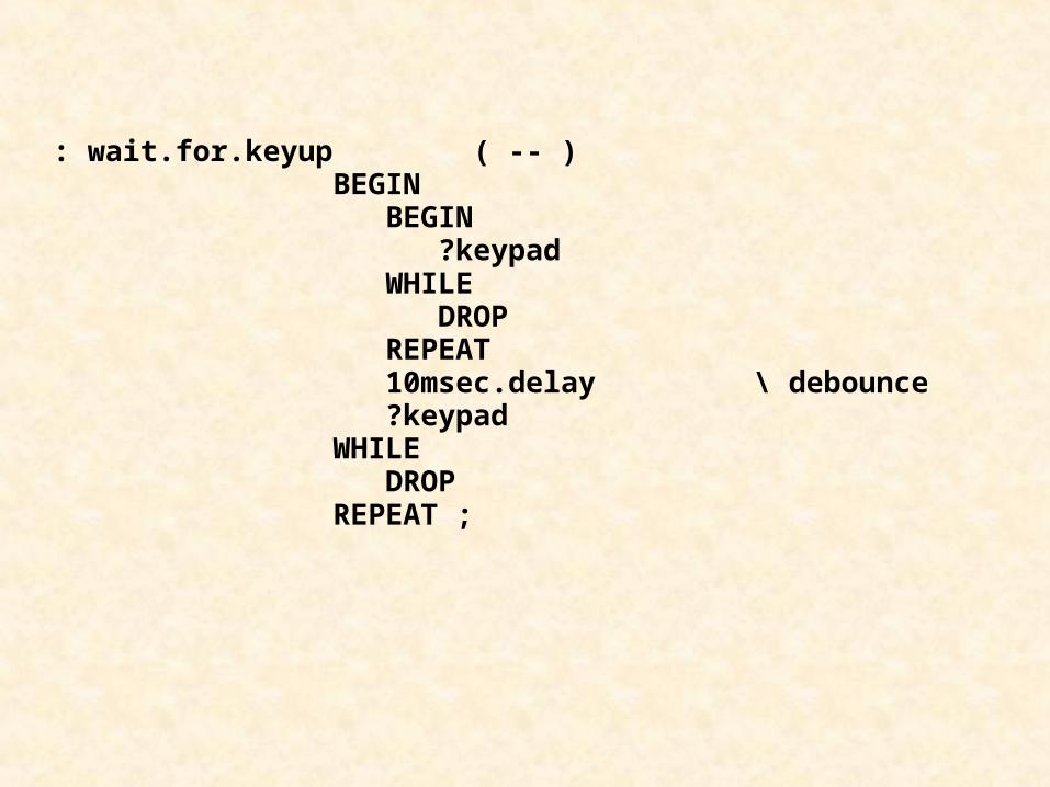
: wait.for.keyup ( -- ) BEGIN BEGIN ?keypad WHILE DROP REPEAT 10msec.delay \ debounce ?keypad WHILE DROP REPEAT ;
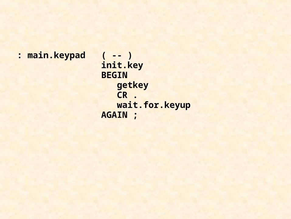
: main.keypad ( -- ) init.key BEGIN getkey CR . wait.for.keyup AGAIN ;
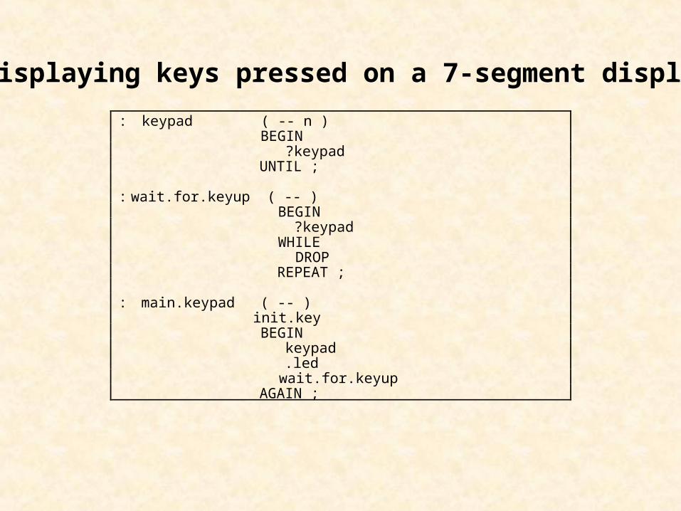
: keypad ( -- n ) BEGIN ?keypad UNTIL ;
: wait.for.keyup ( -- ) BEGIN ?keypad WHILE DROP REPEAT ;
: main.keypad ( -- ) init.key BEGIN keypad .led wait.for.keyup AGAIN ;
Displaying keys pressed on a 7-segment display
DECIMAL
: getkey ( -- n ) BEGIN keypad \ n1 10MS.DELAY \ debounce keypad \ n1 n2 OVER <> \ n1 f WHILE DROP REPEAT ;
: wait.for.keyup ( -- ) BEGIN BEGIN ?keypad WHILE DROP REPEAT 10MS.DELAY \ debounce ?keypad WHILE DROP REPEAT ;
Including debounce when reading a keypad
1
2
3
4
5
6
7
9
8
Vcc
ROW Y3
ROW Y4
OSC
KB MASK
COL X4
COL X3
ROW Y2
ROW Y1
DATA OUT A
DATA OUT D
OUT EN
DATA AV
COL X1
COL X2
DATA OUT C
DATA OUT B
18
17
16
15
14
13
12
11
10GND
MM74C922
PJ0
PJ1
PJ2
PJ3
PJ7
0.1f
1.0f
X1 X2 X3 X4 Y4 Y3 Y2 Y1
NC
0123
4567
89B
C
A
DEF
1 2 3
4 5 6
7 8 9
0A B
C
D
E
F
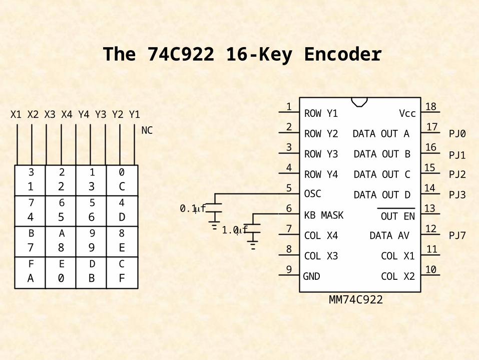
The 74C922 16-Key Encoder
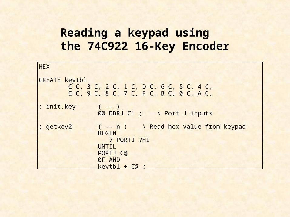
Reading a keypad using the 74C922 16-Key Encoder
HEX
CREATE keytbl C C, 3 C, 2 C, 1 C, D C, 6 C, 5 C, 4 C, E C, 9 C, 8 C, 7 C, F C, B C, 0 C, A C,
: init.key ( -- ) 00 DDRJ C! ; \ Port J inputs
: getkey2 ( -- n ) \ Read hex value from keypad BEGIN 7 PORTJ ?HI UNTIL PORTJ C@ 0F AND keytbl + C@ ;
74154
15141320
1011
123456
9
78
1617
1819
21
22
23A
B
C
D
123456
9
78
0
12
1011
151413
PB0
PB1
PB2
PB3
STRB
+5V
STRA
10K
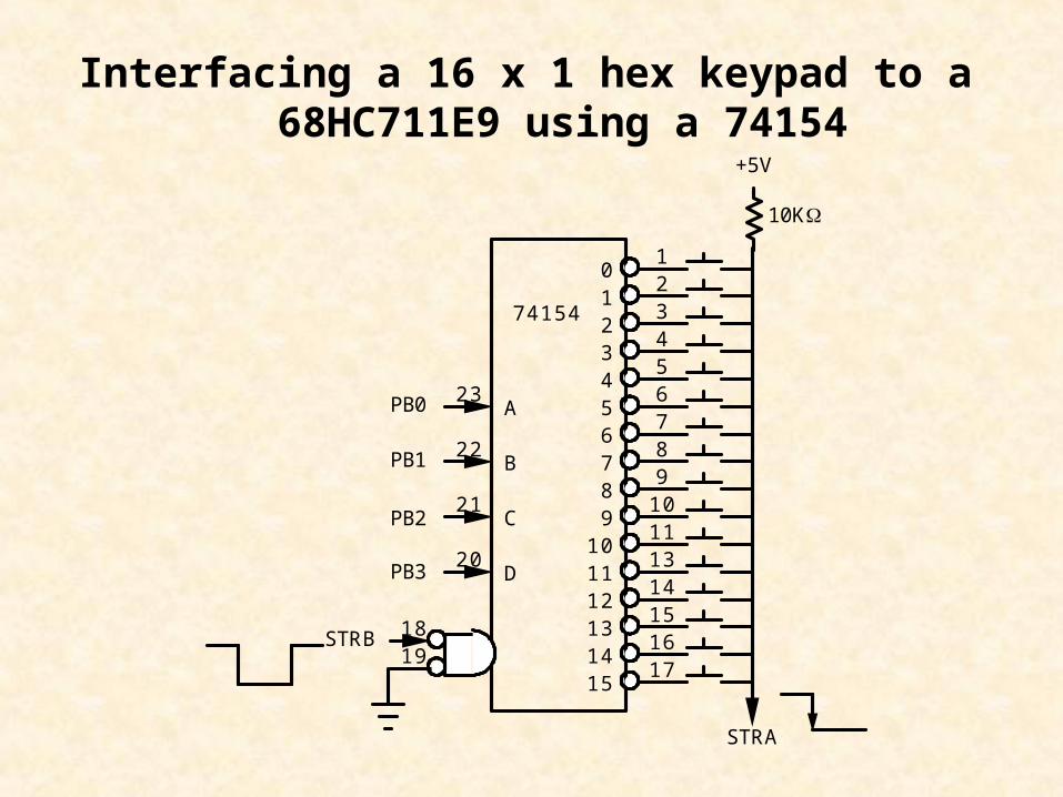
Interfacing a 16 x 1 hex keypad to a 68HC711E9 using a 74154
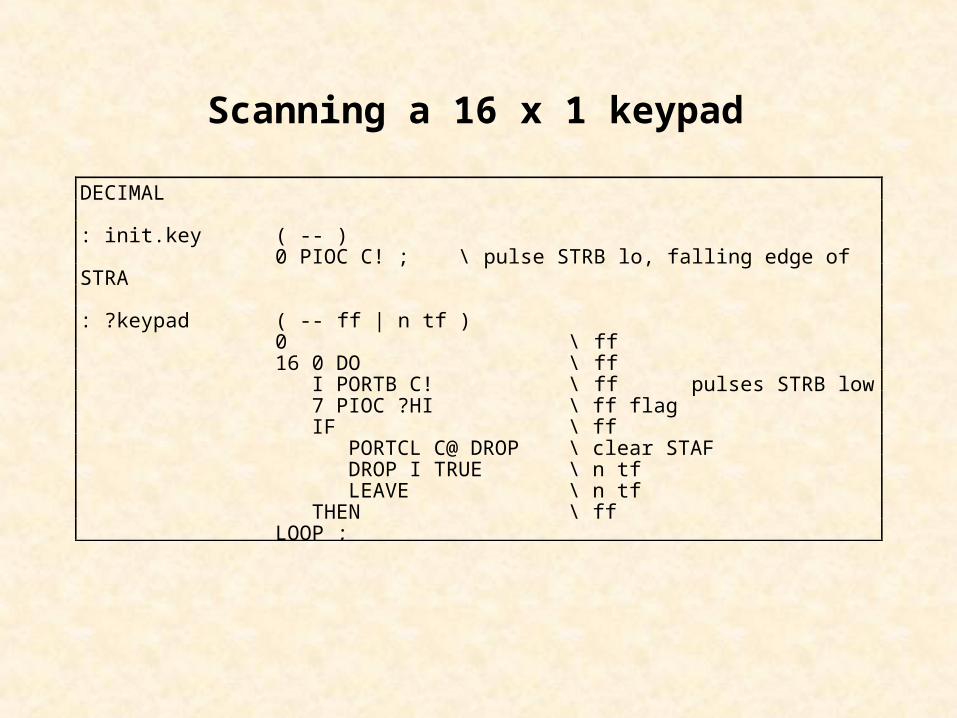
DECIMAL
: init.key ( -- ) 0 PIOC C! ; \ pulse STRB lo, falling edge ofSTRA
: ?keypad ( -- ff | n tf ) 0 \ ff 16 0 DO \ ff I PORTB C! \ ff pulses STRB low 7 PIOC ?HI \ ff flag IF \ ff PORTCL C@ DROP \ clear STAF DROP I TRUE \ n tf LEAVE \ n tf THEN \ ff LOOP ;
Scanning a 16 x 1 keypad
Parallel Interfacing
• Parallel I/O Ports
• Using Parallel Ports
• Seven-Segment Displays
• Keypad Interfacing
• Liquid Crystal Displays
• Interrupt-Driven Traffic Lights
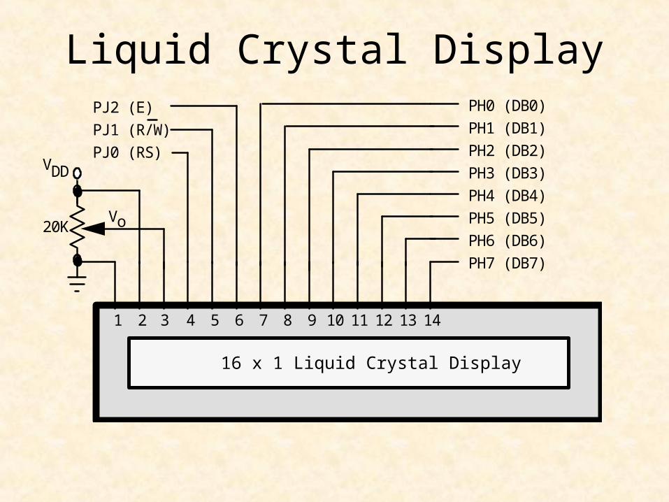
Liquid Crystal Display
2 3 4 5 6 7 9 101 8 11 12 13 14
16 x 1 Liquid Crystal Display
PJ2 (E)
PJ1 (R/W)
PJ0 (RS)VDD
Vo20K
PH0 (DB0)
PH1 (DB1)
PH2 (DB2)
PH3 (DB3)
PH4 (DB4)
PH5 (DB5)
PH6 (DB6)
PH7 (DB7)
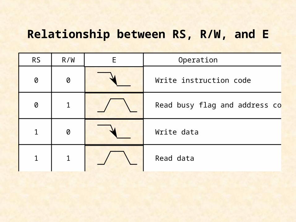
RS R/W E
0 0
0 1
1 0
1
Operation
Write instruction code
Read busy flag and address counter
Write data
Read data1
Relationship between RS, R/W, and E

Table 7.4 HD44780 Instruction SetInstruction DB7 DB6 DB5 DB4 DB3 DB2 DB1 DB0 Description
Clear display 0 0 0 0 0 0 0 1 Clears display & returns cursor to home.Sets I/D=1 in Entry Mode.
Return home 0 0 0 0 0 0 1 x Returns cursor to home position (Address 0)Set DD RAM address to zero.
Entry mode set 0 0 0 0 0 1 I/D S I/D=1: increment cursor; S=0: normal ;I/D=0: decrement cursor; S=1 shift display.
Display ON/OFFcontrol
0 0 0 0 1 D C B Sets ON/OFF all display (D), cursor (C),and blink of cursor (B).
Cursor or displayshift
0 0 0 1 S/C R/L x x S/C=1: display shift; S/C=0: cursor move;R/L=1: shift right; R/L=0: shift left.
Function set 0 0 1 DL N F x x DL=1: 8 bits; DL=0: 4 bits; N=1: 2 line;N=0: 1 line; F=1: 5x10 dots; F=0; 5x7 dots.
Set the CG RAMaddress
0 1 CG RAM address Sets the CG RAM address, after whichCG RAM data is sent and received.
Set the DD RAMaddress
1 DD RAM address Sets the DD RAM address, after whichDD RAM data is sent and received.
Read busy flag &address
BF Address counter Read busy flag (BF) and address countercontents.
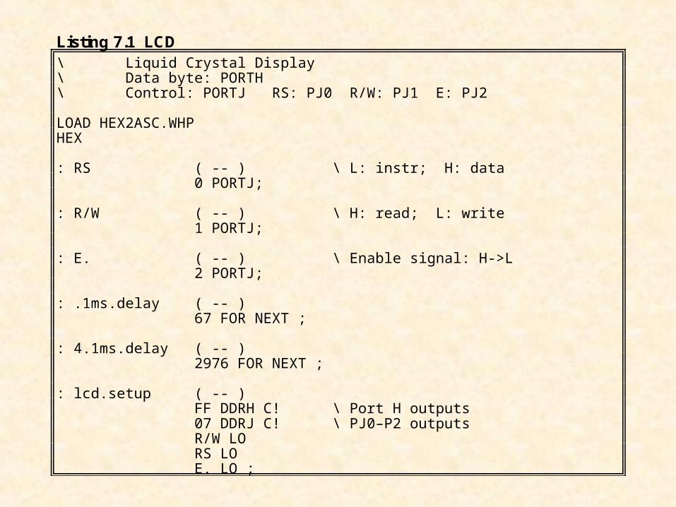
Listing 7.1 LCD\ Liquid Crystal Display\ Data byte: PORTH\ Control: PORTJ RS: PJ0 R/W: PJ1 E: PJ2
LOAD HEX2ASC.WHPHEX
: RS ( -- ) \ L: instr; H: data 0 PORTJ;
: R/W ( -- ) \ H: read; L: write 1 PORTJ;
: E. ( -- ) \ Enable signal: H->L 2 PORTJ;
: .1ms.delay ( -- ) 67 FOR NEXT ;
: 4.1ms.delay ( -- ) 2976 FOR NEXT ;
: lcd.setup ( -- ) FF DDRH C! \ Port H outputs 07 DDRJ C! \ PJ0–P2 outputs R/W LO RS LO E. LO ;
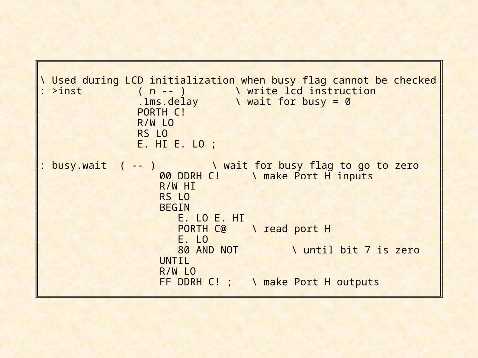
\ Used during LCD initialization when busy flag cannot be checked: >inst ( n -- ) \ write lcd instruction .1ms.delay \ wait for busy = 0 PORTH C! R/W LO RS LO E. HI E. LO ;
: busy.wait ( -- ) \ wait for busy flag to go to zero00 DDRH C! \ make Port H inputsR/W HIRS LOBEGIN
E. LO E. HI PORTH C@ \ read port H E. LO 80 AND NOT \ until bit 7 is zero
UNTILR/W LOFF DDRH C! ; \ make Port H outputs
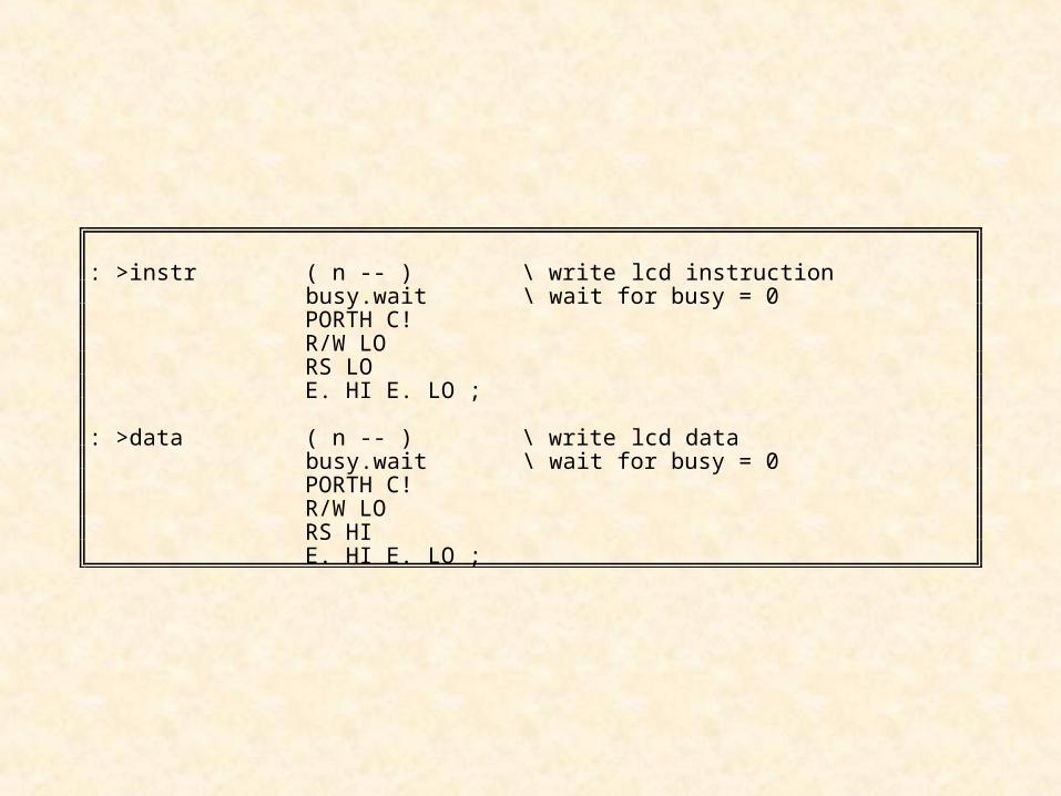
: >instr ( n -- ) \ write lcd instruction busy.wait \ wait for busy = 0 PORTH C! R/W LO RS LO E. HI E. LO ;
: >data ( n -- ) \ write lcd data busy.wait \ wait for busy = 0 PORTH C! R/W LO RS HI E. HI E. LO ;
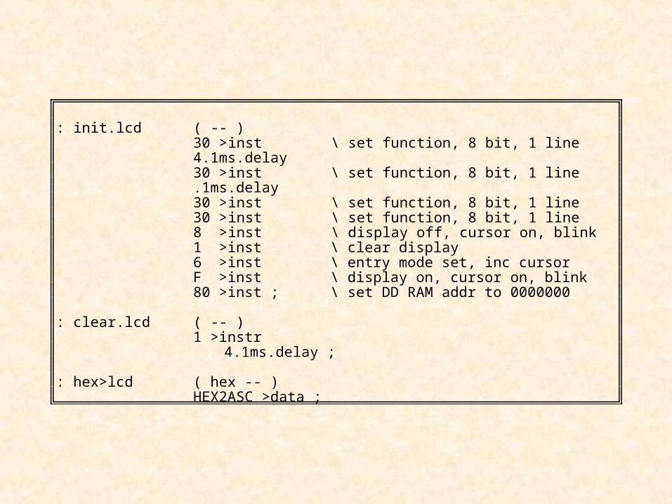
: init.lcd ( -- ) 30 >inst \ set function, 8 bit, 1 line 4.1ms.delay 30 >inst \ set function, 8 bit, 1 line .1ms.delay 30 >inst \ set function, 8 bit, 1 line 30 >inst \ set function, 8 bit, 1 line 8 >inst \ display off, cursor on, blink 1 >inst \ clear display 6 >inst \ entry mode set, inc cursor F >inst \ display on, cursor on, blink 80 >inst ; \ set DD RAM addr to 0000000
: clear.lcd ( -- ) 1 >instr
4.1ms.delay ;
: hex>lcd ( hex -- ) HEX2ASC >data ;
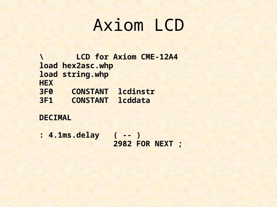
Axiom LCD
\ LCD for Axiom CME-12A4load hex2asc.whpload string.whpHEX3F0 CONSTANT lcdinstr3F1 CONSTANT lcddata
DECIMAL
: 4.1ms.delay ( -- ) 2982 FOR NEXT ;
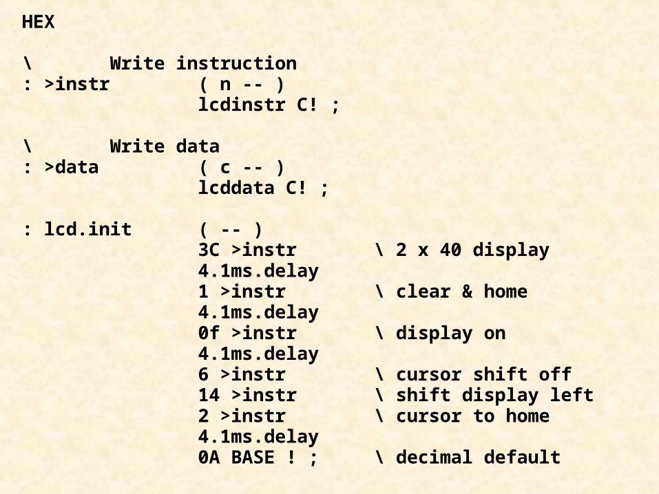
HEX
\ Write instruction: >instr ( n -- ) lcdinstr C! ;
\ Write data: >data ( c -- ) lcddata C! ;
: lcd.init ( -- ) 3C >instr \ 2 x 40 display 4.1ms.delay 1 >instr \ clear & home 4.1ms.delay 0f >instr \ display on 4.1ms.delay 6 >instr \ cursor shift off 14 >instr \ shift display left 2 >instr \ cursor to home 4.1ms.delay 0A BASE ! ; \ decimal default

Table 7.4 HD44780 Instruction SetInstruction DB7 DB6 DB5 DB4 DB3 DB2 DB1 DB0 Description
Clear display 0 0 0 0 0 0 0 1 Clears display & returns cursor to home.Sets I/D=1 in Entry Mode.
Return home 0 0 0 0 0 0 1 x Returns cursor to home position (Address 0)Set DD RAM address to zero.
Entry mode set 0 0 0 0 0 1 I/D S I/D=1: increment cursor; S=0: normal ;I/D=0: decrement cursor; S=1 shift display.
Display ON/OFFcontrol
0 0 0 0 1 D C B Sets ON/OFF all display (D), cursor (C),and blink of cursor (B).
Cursor or displayshift
0 0 0 1 S/C R/L x x S/C=1: display shift; S/C=0: cursor move;R/L=1: shift right; R/L=0: shift left.
Function set 0 0 1 DL N F x x DL=1: 8 bits; DL=0: 4 bits; N=1: 2 line;N=0: 1 line; F=1: 5x10 dots; F=0; 5x7 dots.
Set the CG RAMaddress
0 1 CG RAM address Sets the CG RAM address, after whichCG RAM data is sent and received.
Set the DD RAMaddress
1 DD RAM address Sets the DD RAM address, after whichDD RAM data is sent and received.
Read busy flag &address
BF Address counter Read busy flag (BF) and address countercontents.
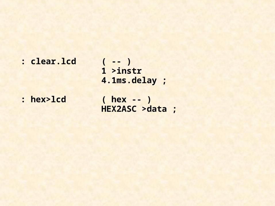
: clear.lcd ( -- ) 1 >instr 4.1ms.delay ;
: hex>lcd ( hex -- ) HEX2ASC >data ;
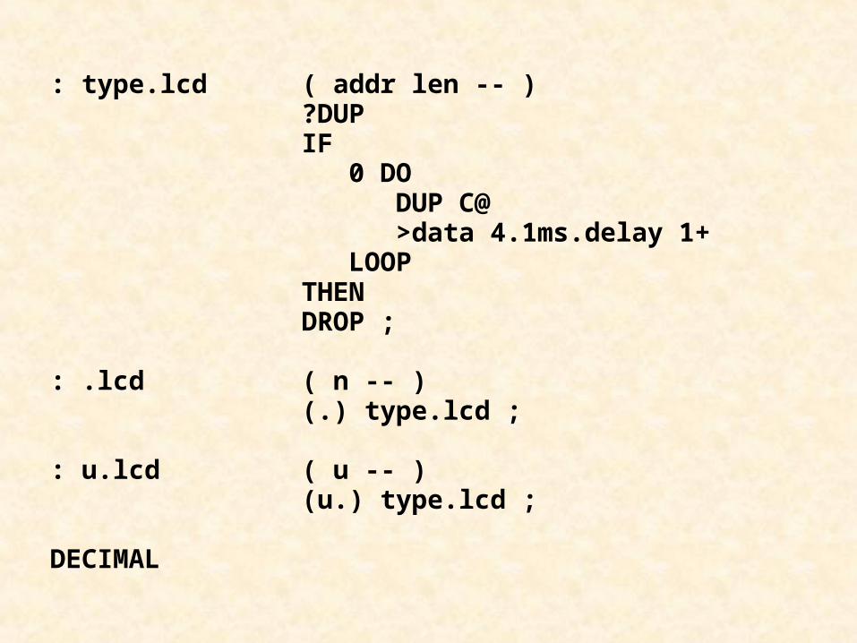
: type.lcd ( addr len -- ) ?DUP IF 0 DO DUP C@ >data 4.1ms.delay 1+ LOOP THEN DROP ;
: .lcd ( n -- ) (.) type.lcd ;
: u.lcd ( u -- ) (u.) type.lcd ;
DECIMAL
Parallel Interfacing
• Parallel I/O Ports
• Using Parallel Ports
• Seven-Segment Displays
• Keypad Interfacing
• Liquid Crystal Displays
• Interrupt-Driven Traffic Lights
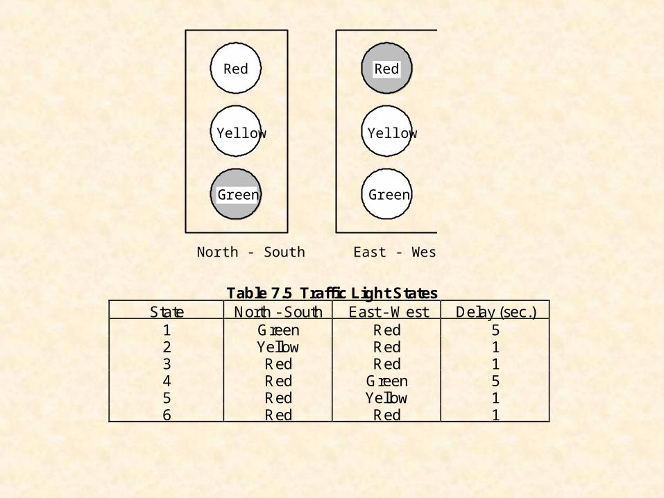
Yellow
Red
Green
Yellow
Red
Green
North - South East - West
Table 7.5 Traffic Light StatesState North - South East - West Delay (sec.)
1 Green Red 52 Yellow Red 13 Red Red 14 Red Green 55 Red Yellow 16 Red Red 1
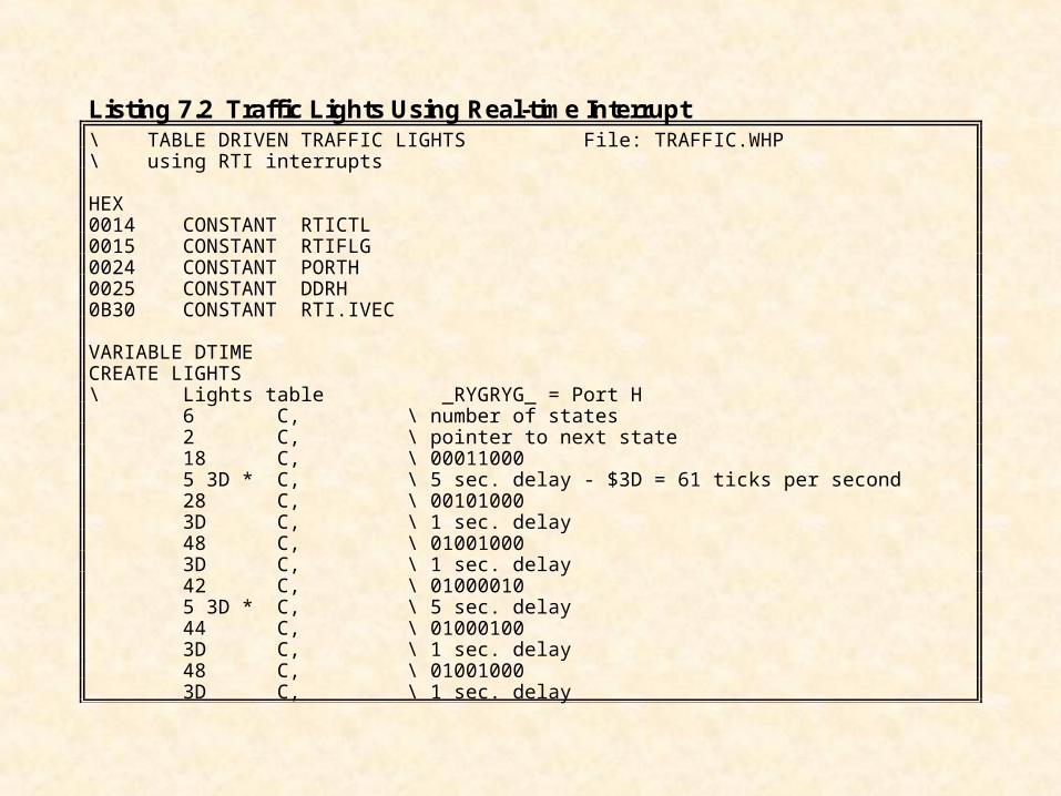
Listing 7.2 Traffic Lights Using Real-time Interrupt\ TABLE DRIVEN TRAFFIC LIGHTS File: TRAFFIC.WHP\ using RTI interrupts
HEX0014 CONSTANT RTICTL0015 CONSTANT RTIFLG0024 CONSTANT PORTH0025 CONSTANT DDRH0B30 CONSTANT RTI.IVEC
VARIABLE DTIMECREATE LIGHTS\ Lights table _RYGRYG_ = Port H 6 C, \ number of states 2 C, \ pointer to next state 18 C, \ 00011000 5 3D * C, \ 5 sec. delay - $3D = 61 ticks per second 28 C, \ 00101000 3D C, \ 1 sec. delay 48 C, \ 01001000 3D C, \ 1 sec. delay 42 C, \ 01000010 5 3D * C, \ 5 sec. delay 44 C, \ 01000100 3D C, \ 1 sec. delay 48 C, \ 01001000 3D C, \ 1 sec. delay
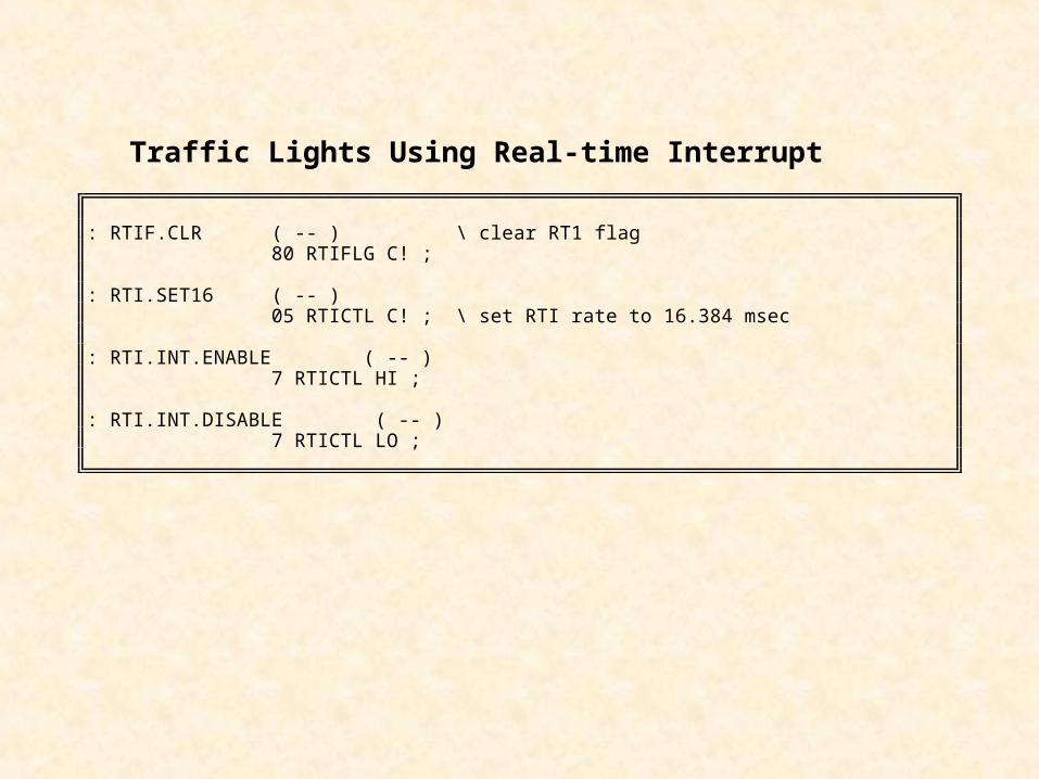
: RTIF.CLR ( -- ) \ clear RT1 flag 80 RTIFLG C! ;
: RTI.SET16 ( -- ) 05 RTICTL C! ; \ set RTI rate to 16.384 msec
: RTI.INT.ENABLE ( -- ) 7 RTICTL HI ;
: RTI.INT.DISABLE ( -- ) 7 RTICTL LO ;
Traffic Lights Using Real-time Interrupt
Traffic Lights Using Real-time Interrupt
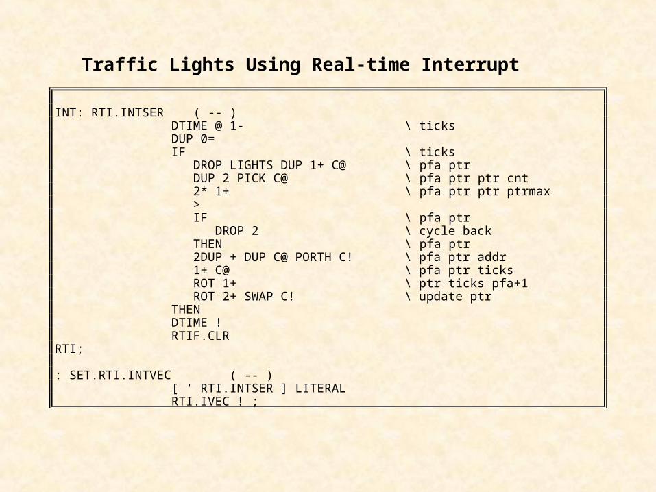
INT: RTI.INTSER ( -- ) DTIME @ 1- \ ticks DUP 0= IF \ ticks DROP LIGHTS DUP 1+ C@ \ pfa ptr DUP 2 PICK C@ \ pfa ptr ptr cnt 2* 1+ \ pfa ptr ptr ptrmax > IF \ pfa ptr DROP 2 \ cycle back THEN \ pfa ptr 2DUP + DUP C@ PORTH C! \ pfa ptr addr 1+ C@ \ pfa ptr ticks ROT 1+ \ ptr ticks pfa+1 ROT 2+ SWAP C! \ update ptr THEN DTIME ! RTIF.CLRRTI;
: SET.RTI.INTVEC ( -- ) [ ' RTI.INTSER ] LITERAL RTI.IVEC ! ;
Traffic Lights Using Real-time Interrupt
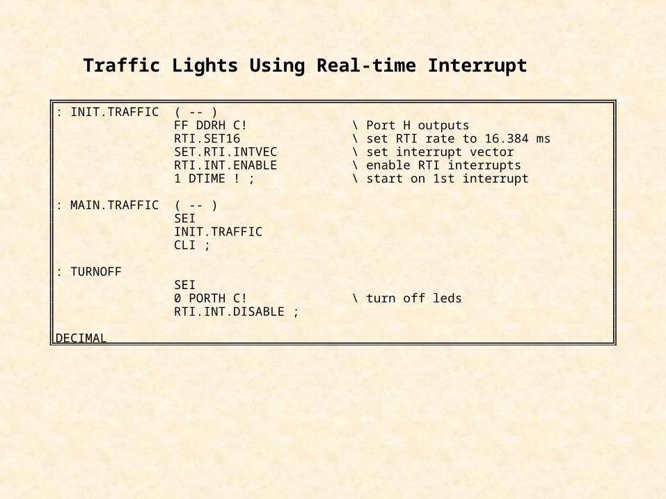
: INIT.TRAFFIC ( -- ) FF DDRH C! \ Port H outputs RTI.SET16 \ set RTI rate to 16.384 ms SET.RTI.INTVEC \ set interrupt vector RTI.INT.ENABLE \ enable RTI interrupts 1 DTIME ! ; \ start on 1st interrupt
: MAIN.TRAFFIC ( -- ) SEI INIT.TRAFFIC CLI ;
: TURNOFF SEI 0 PORTH C! \ turn off leds RTI.INT.DISABLE ;
DECIMAL
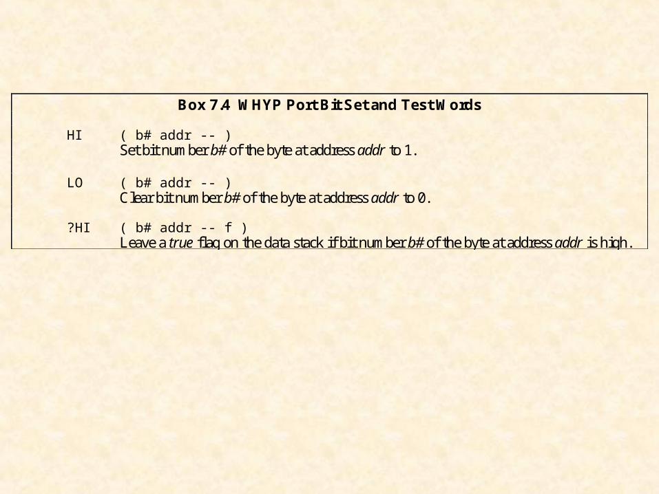
Box 7.4 WHYP Port Bit Set and Test Words
HI ( b# addr -- )Set bit number b# of the byte at address addr to 1.
LO ( b# addr -- )Clear bit number b# of the byte at address addr to 0.
?HI ( b# addr -- f )Leave a true flag on the data stack if bit number b# of the byte at address addr is high.


![UNIT-III PERIPHERALS INTERFACING Interfacing of 8085 with ... · Interfacing of 8085 with: Keyboard & display unit [8279 IC] – Parallel peripheral interface [8255] – Interrupt](https://static.fdocuments.in/doc/165x107/6062398b1448165f2313a7e4/unit-iii-peripherals-interfacing-interfacing-of-8085-with-interfacing-of-8085.jpg)