PAPER PoweringaVentricularAssist Device(VAD)Withthe Free … · 2012-11-17 · Device(VAD)Withthe...
12
INVITED PAPER Powering a Ventricular Assist Device (VAD) With the Free-Range Resonant Electrical Energy Delivery (FREE-D) System This paper discusses wireless delivery of power from a distant source to an implanted cardiac device, and it proposes recharging implanted batteries using magnetically coupled resonators. By Benjamin H. Waters, Student Member IEEE , Alanson P. Sample, Student Member IEEE , Pramod Bonde, Member IEEE , and Joshua R. Smith, Member IEEE ABSTRACT | Wireless data communication technology has eliminated wired connections for data transfer to portable de- vices. Wireless power technology offers the possibility of eliminating the remaining wired connection: the power cord. For ventricular assist devices (VADs), wireless power technol- ogy will eliminate the complications and infections caused by the percutaneous wired power connection. Integrating wireless power technology into VADs will enable VAD implants to be- come a more viable option for heart failure patients (of which there are 80 000 in the United States each year) than heart transplants. Previous transcutaneous energy transfer systems (TETS) have attempted to wirelessly power VADs [1]; however, TETS-based technologies are limited in range to a few milli- meters, do not tolerate angular misalignment, and suffer from poor efficiency. The free-range resonant electrical delivery (FREE-D) wireless power system aims to use magnetically coupled resonators to efficiently transfer power across a dis- tance to a VAD implanted in the human body, and to provide robustness to geometric changes. Multiple resonator config- urations are implemented to improve the range and efficiency of wireless power transmission to both a commercially avail- able axial pump [2] and a VentrAssist centrifugal pump [3]. An adaptive frequency tuning method allows for maximum power transfer efficiency for nearly any angular orientation over a range of separation distances. Additionally, laboratory results show the continuous operation of both pumps using the FREE-D system with a wireless power transfer efficiency up- wards of 90%. KEYWORDS | Magnetically coupled resonators; ventricular assist device (VAD); wireless power I. INTRODUCTION Wireless power transfer using inductive coupling is be- coming increasingly popular for consumer electronic de- vices. Commercial applications include wireless charging pads, electronic toothbrushes, induction cookers, and electric car battery chargers. However, none of these ap- plications enable the geometric freedom that the term Bwireless power[ suggests. Charging pads and electric toothbrushes require that the device be placed very close by or directly on top of the charging pad. This is because the efficiency for inductively coupled wireless power Manuscript received July 5, 2011; accepted August 10, 2011. Date of publication October 3, 2011; date of current version December 21, 2011. B. H. Waters, A. P. Sample, and J. R. Smith are with the Electrical Engineering Department, University of Washington, Seattle, WA 98195-2500 USA (e-mail: [email protected]). P. Bonde is with the Yale School of Medicine, New Haven, CT 06520 USA. Digital Object Identifier: 10.1109/JPROC.2011.2165309 138 Proceedings of the IEEE | Vol. 100, No. 1, January 2012 0018-9219/$26.00 Ó2011 IEEE
Transcript of PAPER PoweringaVentricularAssist Device(VAD)Withthe Free … · 2012-11-17 · Device(VAD)Withthe...

INV ITEDP A P E R
Powering a Ventricular AssistDevice (VAD) With theFree-Range ResonantElectrical Energy Delivery(FREE-D) SystemThis paper discusses wireless delivery of power from a distant source to an
implanted cardiac device, and it proposes recharging implanted batteries
using magnetically coupled resonators.
By Benjamin H. Waters, Student Member IEEE, Alanson P. Sample, Student Member IEEE,
Pramod Bonde, Member IEEE, and Joshua R. Smith, Member IEEE
ABSTRACT | Wireless data communication technology has
eliminated wired connections for data transfer to portable de-
vices. Wireless power technology offers the possibility of
eliminating the remaining wired connection: the power cord.
For ventricular assist devices (VADs), wireless power technol-
ogy will eliminate the complications and infections caused by
the percutaneous wired power connection. Integrating wireless
power technology into VADs will enable VAD implants to be-
come a more viable option for heart failure patients (of which
there are 80 000 in the United States each year) than heart
transplants. Previous transcutaneous energy transfer systems
(TETS) have attempted to wirelessly power VADs [1]; however,
TETS-based technologies are limited in range to a few milli-
meters, do not tolerate angular misalignment, and suffer from
poor efficiency. The free-range resonant electrical delivery
(FREE-D) wireless power system aims to use magnetically
coupled resonators to efficiently transfer power across a dis-
tance to a VAD implanted in the human body, and to provide
robustness to geometric changes. Multiple resonator config-
urations are implemented to improve the range and efficiency
of wireless power transmission to both a commercially avail-
able axial pump [2] and a VentrAssist centrifugal pump [3]. An
adaptive frequency tuning method allows for maximum power
transfer efficiency for nearly any angular orientation over a
range of separation distances. Additionally, laboratory results
show the continuous operation of both pumps using the
FREE-D system with a wireless power transfer efficiency up-
wards of 90%.
KEYWORDS | Magnetically coupled resonators; ventricular
assist device (VAD); wireless power
I . INTRODUCTION
Wireless power transfer using inductive coupling is be-
coming increasingly popular for consumer electronic de-
vices. Commercial applications include wireless charging
pads, electronic toothbrushes, induction cookers, and
electric car battery chargers. However, none of these ap-
plications enable the geometric freedom that the term
Bwireless power[ suggests. Charging pads and electrictoothbrushes require that the device be placed very close
by or directly on top of the charging pad. This is because
the efficiency for inductively coupled wireless power
Manuscript received July 5, 2011; accepted August 10, 2011. Date of publication
October 3, 2011; date of current version December 21, 2011.
B. H. Waters, A. P. Sample, and J. R. Smith are with the Electrical Engineering
Department, University of Washington, Seattle, WA 98195-2500 USA (e-mail:
P. Bonde is with the Yale School of Medicine, New Haven, CT 06520 USA.
Digital Object Identifier: 10.1109/JPROC.2011.2165309
138 Proceedings of the IEEE | Vol. 100, No. 1, January 2012 0018-9219/$26.00 �2011 IEEE

transfer systems drops off rapidly as the distance betweenthe transmitter (Tx) and the receiver (Rx) increases.
Range and mobility can be increased with resonant
coupling techniques. The free-range resonant electrical
delivery (FREE-D) system enables true wireless power
transfer by allowing devices to be charged in free space,
without direct physical contact between the Tx and the Rx.
Within the FREE-D system’s working range, power trans-
fer efficiency can be held constant even as Tx–Rx distanceand orientation change; beyond the working range, effi-
ciency drops. The working range is dependent on the size
of the Tx and Rx resonators: as a rule of thumb, the work-
ing range is on the order of the resonator diameter [4].
In this work, we demonstrate that the FREE-D system
is able to wirelessly power a ventricular assist device
(VAD). First, the benefits of implementing wireless power
to the VAD are discussed. A circuit model of the FREE-Dresonators is then presented and the system is experi-
mentally tested with two different VADs. This paper also
presents a novel range adaptation technique that allows
single-frequency operation. Additionally, a method for ex-
tending the range of the FREE-D system using relay reso-
nators is presented.
II . THE NEED FOR MAGNETICALLYCOUPLED RESONATORS INMEDICAL APPLICATIONS
A. The Wireless Power SolutionThe applications that can currently benefit most from
resonantly coupled wireless power transfer systems are
those that require dynamic charging, large separation dis-tances between the Tx and the Rx, and do not have highly
conductive materials around the resonators that can limit
the wireless power transfer range. The VAD fits all of these
ideal requirements in that the patient is actively moving
and consequently constantly changing the distance and
angle between the Tx resonator and the implanted Rx re-
sonator, and the integration of wireless power will hugely
benefit the technology in general because the potentiallyinfectious percutaneous driveline will be eliminated.
B. The Medical ProblemHeart failure is a terminal disease with a very poor
prognosis and constitutes Medicare’s greatest area of
spending with annual spending close to $35 billion [5].
The most desirable treatment for heart failure remains a
full heart transplant, however, only a limited number(approximately 2000 per year) of patients can benefit from
transplants due to donor shortages and high costs. An
alternative which has become increasingly popular is
mechanical circulatory assistance with ventricular assist
devices in which a pump with a central rotor accelerates
blood throughout the body [2], [3]. The first generation
VADs were approved for use in the United States by the
Food and Drug Administration (FDA) in October 1994.
The pumps require a percutaneous driveline, meaning a
biocompatible cable protrudes from the body to connect
the VAD to a power source and the VAD system controller.
The system controller communicates with the heart pump
to modify pump conditions and simultaneously provide
power to the VAD from either a battery for portable use or
a central power supply unit (PSU). The typical configu-ration for a VAD can be seen in Fig. 1. VAD technology has
significantly improved in the past 15 years. Initially, VADs
were a temporary alternative solution to heart transplants:
supporting patients for only a few months. Now, VADs can
survive patients for upwards of five years [6], [7]. As a
result of the extended lifetime of the VAD, the most
common cause for patient readmission to the hospital and
patient death is no longer the technical failure of the VAD,but rather the exit site infection (ESI) from the percuta-
neous driveline. The increasing risk of ESI hampers the
patient’s quality of life and can lead to repeated hospita-
lizations for antibiotic treatment, surgical interventions, or
even a costly VAD replacement [14].
Medical research has demonstrated the relationship
between ESI, pump pocket infectionVinfection in the
abdominal pocket where the VADs are implantedVandsubsequent sepsisVbacterial growth in the bloodstream
[8]–[13]. Seventy percent of VAD patients’ first readmis-
sion to the hospital is due to ESI [14]. Patients who develop
ESI spend more time in the hospital and have ten times as
many readmissions as the patients without ESI [15]. The
net result of these effects from ESI is the reduced survival
and increased cost negating the intended benefit of VAD
therapy. Implementing the FREE-D wireless power systemto power the VAD pump will eliminate the need for the
percutaneous driveline, and consequently eliminate ESI.
C. Limitations With Inductive Charging Usingthe TETS System
Previous attempts have been made to wirelessly power
VADs using transcutaneous energy transfer systems
(TETS) [16]–[19]. TETS uses inductive coupling tech-
niques to transfer power between coils on the inner and
outer surfaces of the skin. After several decades of
Fig. 1. Typical configuration for a VAD showing the power base unit
(PBU) directly charging the VAD system controller, which is controlled
by the system monitor (typically a laptop) to power the VAD and define
pump operating conditions. The PBU can be temporarily replaced
with a battery for portable use away from an electrical outlet.
Waters et al. : Powering a Ventricular Assist Device (VAD) With the FREE-D System
Vol. 100, No. 1, January 2012 | Proceedings of the IEEE 139

laboratory testing and prototype development, the clinicalapplication of TETS has been possible in only two systems
(Arrow LionHeart and AbioCor TAH) [17], [18]. The cli-
nical and laboratory experiments have demonstrated
several drawbacks with the current TETS technology.
Restrictions on misalignment between the transmitting
and receiving coils and the necessity for a close separation
distance between the coils limit the practicality of TETS.
The system also incurs significant wireless energy lossbeyond 10-cm separation. The proximity limitation
requires that the receiving coil be implanted just under
the skin and the external transmitting coil be secured in a
single position on the skin surface with adhesives. For
angular misalignments or excessive separation between
the coils, the transmitter will attempt to supply more
power to account for the reduced efficiency. This effect has
proven to cause skin irritability and thermal injury fromthe increase in coil temperature due to greater power
transmission, which can result in burns and lead to in-
fection on the exterior surface of the skin. The TETS tech-
nology was first implemented with the Arrow LionHeart
VAD in 2001; however, it has since been withdrawn from
the market [18].
D. Improvements With Resonant CouplingUsing the FREE-D System
The FREE-D system provides wireless power to a VAD
using strong resonant coupling technology. FREE-D
affords seamless energy supply without compromising
mobility or requiring direct contact between the individual
and energy source as in TETS. The FREE-D wireless power
resonators efficiently transfer power across meter dis-
tances to a VAD implanted in the human body [20], [21].The Tx and Rx resonators are coils of wire that are tuned to
resonate at a specific frequency. The resonator size and
shape can be modified to accommodate application specifi-
cations, such as room size and patient body geometry.
The key feature that distinguishes FREE-D from prior
inductive schemes is the use of high-quality factor (Q fac-
tor) resonators combined with an automatic tuning
scheme that keeps the system operating at maximumefficiency. The FREE-D system is able to adapt to varia-
tions in Tx–Rx separation distances, Tx–Rx orientations,
and power requirements of the load. By actively control-
ling the frequency of the transmitted radio-frequency (RF)
signal, the FREE-D system can achieve high power transfer
efficiencyVupwards of 90%Vfor nearly any angular
orientation over a range of separation distances [4], [20],
[21]. Table 1 summarizes the advantages of the FREE-Dsystem over the previous TETS systems.
E. Grand Vision of the FREE-D SystemThe grand vision for implementing the FREE-D system
with a VAD will consist of installing multiple Tx resonators
throughout the household that are hidden inside walls,
floors, couches, tables, and beds. There will be two Rx
resonators: one will be installed in an exterior vest that
will be worn by the patient, and another smaller resonator
will be implanted in the human body. The larger size of theRx vest resonator will increase the working range of the
wireless power transfer. The implanted Rx resonator will
be situated at a fixed distance away from the Rx vest reso-
nator to ensure seamless energy transfer to the VAD.
Therefore, the patient will be free to maneuver throughout
their home while receiving wireless power from the
nearest Tx resonator. Alternatively, if the patient needs to
leave the home, a portable battery can temporarily providepower to the external Rx vest resonator, which will wire-
lessly provide power to the implanted Rx resonator and
the VAD.
III . OVERVIEW OF THE FREE-D SYSTEM
Unlike some of the existing inductively coupled wireless
power technologies currently available for consumer elec-tronics, the FREE-D system requires dynamic power
management control to operate at its full potential for
improved efficiency over larger distances. The following
sections outline the FREE-D wireless power circuit model
as well as the additional power management circuitry. An
extended analysis of the basic circuit model for magnet-
ically coupled resonators is shown in [4].
A. Wireless Power Circuit ModelFig. 2 shows a diagram of the basic FREE-D wireless
power system. The two-element transmitter consists of a
single-turn drive resonator and multiturn resonator that
wirelessly transmits power to a two-element receiver.
These two resonant systems efficiently exchange energy by
sharing nonradiative magnetic fields that oscillate at a
Table 1 Comparison of Proposed FREE-D System Versus
Existing TETS System
Waters et al.: Powering a Ventricular Assist Device (VAD) With the FREE-D System
140 Proceedings of the IEEE | Vol. 100, No. 1, January 2012
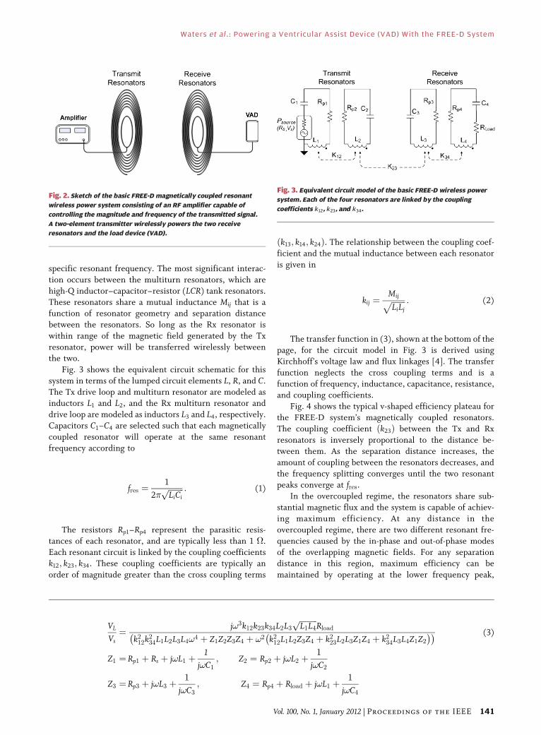
specific resonant frequency. The most significant interac-
tion occurs between the multiturn resonators, which are
high-Q inductor–capacitor–resistor (LCR) tank resonators.
These resonators share a mutual inductance Mij that is afunction of resonator geometry and separation distance
between the resonators. So long as the Rx resonator is
within range of the magnetic field generated by the Tx
resonator, power will be transferred wirelessly between
the two.
Fig. 3 shows the equivalent circuit schematic for this
system in terms of the lumped circuit elements L, R, and C.
The Tx drive loop and multiturn resonator are modeled asinductors L1 and L2, and the Rx multiturn resonator and
drive loop are modeled as inductors L3 and L4, respectively.
Capacitors C1–C4 are selected such that each magnetically
coupled resonator will operate at the same resonant
frequency according to
fres ¼1
2�ffiffiffiffiffiffiffiffiLiCi
p : (1)
The resistors Rp1–Rp4 represent the parasitic resis-
tances of each resonator, and are typically less than 1 �.
Each resonant circuit is linked by the coupling coefficientsk12; k23; k34. These coupling coefficients are typically an
order of magnitude greater than the cross coupling terms
ðk13; k14; k24Þ. The relationship between the coupling coef-
ficient and the mutual inductance between each resonator
is given in
kij ¼MijffiffiffiffiffiffiffiLiLj
p : (2)
The transfer function in (3), shown at the bottom of the
page, for the circuit model in Fig. 3 is derived using
Kirchhoff’s voltage law and flux linkages [4]. The transfer
function neglects the cross coupling terms and is afunction of frequency, inductance, capacitance, resistance,
and coupling coefficients.
Fig. 4 shows the typical v-shaped efficiency plateau for
the FREE-D system’s magnetically coupled resonators.
The coupling coefficient ðk23Þ between the Tx and Rx
resonators is inversely proportional to the distance be-
tween them. As the separation distance increases, the
amount of coupling between the resonators decreases, andthe frequency splitting converges until the two resonant
peaks converge at fres.
In the overcoupled regime, the resonators share sub-
stantial magnetic flux and the system is capable of achiev-
ing maximum efficiency. At any distance in the
overcoupled regime, there are two different resonant fre-
quencies caused by the in-phase and out-of-phase modes
of the overlapping magnetic fields. For any separationdistance in this region, maximum efficiency can be
maintained by operating at the lower frequency peak,
Fig. 2. Sketch of the basic FREE-D magnetically coupled resonant
wireless power system consisting of an RF amplifier capable of
controlling the magnitude and frequency of the transmitted signal.
A two-element transmitter wirelessly powers the two receive
resonators and the load device (VAD).
Fig. 3. Equivalent circuit model of the basic FREE-D wireless power
system. Each of the four resonators are linked by the coupling
coefficients k12, k23, and k34.
VL
Vs¼ j!3k12k23k34L2L3
ffiffiffiffiffiffiffiffiffiL1L4
pRload
k212k2
34L1L2L3L4!4 þ Z1Z2Z3Z4 þ !2 k212L1L2Z3Z4 þ k2
23L2L3Z1Z4 þ k234L3L4Z1Z2
� �� � (3)
Z1 ¼ Rp1 þ Rs þ j!L1 þ1
j!C1; Z2 ¼ Rp2 þ j!L2 þ
1
j!C2
Z3 ¼ Rp3 þ j!L3 þ1
j!C3; Z4 ¼ Rp4 þ Rload þ j!L1 þ
1
j!C4
Waters et al. : Powering a Ventricular Assist Device (VAD) With the FREE-D System
Vol. 100, No. 1, January 2012 | Proceedings of the IEEE 141

which corresponds to the in-phase mode of the resonant
system.
In the undercoupled regime, the shared flux falls below
a threshold such that maximum efficiency cannot be
achieved. Critical coupling is the point of transition be-
tween these two regimes, and corresponds to the greatest
range at which maximum efficiency can be achieved.Similar to inductive coupling, the undercoupled regime is
still capable of wireless power transfer, but the maximum
achievable efficiency is limited and falls rapidly with
distance.
B. Power Management Circuit ModelPower management control systems are required at
both the Tx and Rx sides of the FREE-D system. The fullblock diagram for the FREE-D system is shown in Fig. 5.
In order to generate the alternating current (ac) wave-
form oscillating at a specific and controllable frequency, a
directional coupler, and microcontroller unit (MCU) have
been implemented with the power amplifier at the Tx side.The power amplifier delivers an RF signal through the
direction coupler to the Tx resonator. The directional
coupler measures the magnitude of the forward and re-
flected waves, which can be used to approximate the
transmission power gain S21 of the resonators. The MCU is
able to minimize the reflected power by adjusting the
amplitude and frequency of the signal delivered to the Tx
resonator so that maximum power transfer will occur be-tween the Tx and Rx resonators.
At the Rx side, an RF-dc bridge rectifier is implemen-
ted to convert the oscillating RF signal to a direct current
(dc) voltage. Next, a dc–dc voltage regulator steps down
this rectified voltage to a constant 13.1 Vdc, which is re-
quired for the system controller and all VADs tested with
the FREE-D system. The regulated dc voltage is delivered
to the system controller, which powers the motor con-troller for the heart pump and monitors VAD conditions
such as flow rate, pump speed, and pump power. Finally, a
diode switch activates or deactivates a backup battery that
can provide power to the system controller intermittently
in case the FREE-D system temporarily fails. This battery
will be rechargeable so that it can be charged by the
FREE-D system without requiring direct access to the im-
planted battery itself, which requires rehospitalization.
IV. TECHNIQUES TO IMPROVEWIRELESS POWER EFFICIENCYOVER DISTANCE
There are regulatory and practical requirements that pre-
sent technical challenges in integrating the FREE-D system
into the homes for VAD patients. The two most significant
difficulties are increasing the range at which highly
efficient wireless power transfer can occur, and operating
within the allowable bandwidth of the ISM bands defined
by the Federal Communications Commission (FCC). Twotechniques are outlined in the following sections to ad-
dress these challenges including the addition of relay
resonators to increase the working range of wireless power
transfer, and a dynamic impedance matching network to
Fig. 5. Block diagram of the complete FREE-D system showing relay resonator and implanted components.
Fig. 4. Efficiency curve for the FREE-D wireless power system
resonators as a function of the coupling coefficient between the
Tx and Rx multiturn resonators and frequency [4] � 2011 IEEE.
Waters et al.: Powering a Ventricular Assist Device (VAD) With the FREE-D System
142 Proceedings of the IEEE | Vol. 100, No. 1, January 2012

enable single-frequency operation in the overcoupledregime.
A. Relay ResonatorsImplementing the grand vision for the application of
the FREE-D system with a VAD will require several Tx
resonators installed throughout the patient’s home. Every
Tx resonator will require its own power supply and power
management system to ensure that the VAD constantlyreceives sufficient power as the distance between the Tx
and Rx resonators increases. However, for central loca-
tions in the household away from walls and accessible
electrical outlets, it will be difficult to provide the neces-
sary equipment for each Tx resonator.
One way to avoid these potential dead zones in the
center of a room would be to increase the range of the
FREE-D system by increasing the size of the Tx and Rxresonators. However, for use with a VAD, the size of the
Rx resonator is limited because it will be implanted in the
body. Therefore, another technique using a relay resonator
as in Fig. 5 can be implemented to accommodate greater
separation distances between Tx and Rx resonators.
When considering the grand vision, this relay resonator
configuration will allow several Tx resonators and the
necessary power management circuitry to be installed inlocations that have concealed access to electrical outlets
(walls and floors), while freestanding relay resonators can
be installed in centralized furniture (chairs, tables, and
desks). These relay resonators will be able to link the
wireless power transferred from the Tx resonators to the
Rx vest resonator worn by the patient.
Adding a relay resonator to the basic resonator model
from Fig. 2 will introduce a third resonant mode to thesystem in the overcoupled regime. The third mode will be
centered at the resonant frequency of the system. Adding
more relay resonators will continue to increase the work-
ing range of the wireless power transfer; however, the
maximum achievable efficiency will decrease and the
number of modes will continue to increase as more relay
resonators are introduced to the system. Nonetheless, the
same power management and frequency tuning algorithmswill be capable of accommodating multiple-mode resonant
systems.
B. Dynamic Frequency Tuning VersusSingle-Frequency Operation
Unlike far-field antennas in which the input impedance
of the antenna is constant, near-field antennas like the
resonators in the FREE-D system have strong electromag-netic field interaction, thus the input impedance of the
resonators is constantly changing as a function of the
coupling or mutual inductance between the Tx and Rx
resonators. As the distance between the Tx and Rx resona-
tors increases, the coupling coefficient between the multi-
turn resonators decreases because the mutual inductance
decreases from (2). The rectifier at the Rx side also has a
complex input impedance that is changing as a function of
the input power and load conditions. As a result, the im-
pedance looking into the Tx resonator is constantly chang-
ing, making it difficult to design an impedance matching
network.
The ideal solution would be to use active frequency
tuning to track the maximum power transfer peaks. How-ever, given the narrow bandwidth requirements for the
ISM bands, frequency tuning will not be possible from a
regulatory standpoint.
Another solution using a dynamic impedance matching
network at the Tx side can be implemented to ensure that
maximum power is transferred to the load at a single
frequency within the ISM band. To demonstrate how this
impedance matching system will work, recall the basictransformer model in Fig. 6 in which maximum power
transfer is achieved when the source and load impedance
are matched according to (4), where N1 and N2 are the
number of turns of the primary and secondary coils,
respectively
Zs ¼N1
N2
� �2
ZL (4)
The FREE-D Tx and Rx resonators can be thought of as
an air-core transformer with complex source and loadimpedances. Therefore, a �-match filter can be imple-
mented as in Fig. 7 to perform conjugate impedance
matching. Similar to changing the turns ratio in the basic
transformer model to perform real impedance matching,
the �-match filter can perform conjugate impedance
matching when proper values of L; Cs, and CL are chosen.
Fig. 6. Basic air-core transformer model with source impedance
Zs and load impedance ZL.
Fig. 7. Basic �-match two-port network to match source impedance
Zs to load impedance ZL.
Waters et al. : Powering a Ventricular Assist Device (VAD) With the FREE-D System
Vol. 100, No. 1, January 2012 | Proceedings of the IEEE 143

Since the source and load impedances vary as the distance
between the Tx and Rx resonators changes, by dynamically
selecting the capacitor values Cs and CL in the �-matchfilter, the source and load impedances will always be
matched.
Rather than using frequency tracking, this impedance
matching technique will deliver maximum power to the
load while operating at a single frequency. Fig. 8 shows
how the �-match filter can be implemented with the
FREE-D system.
A Matlab model has been developed that uses S-parameter data collected from a vector network analyzer
(VNA) for any set of magnetically coupled resonators.
Fig. 9 shows a basic block diagram of how the Matlab
model is implemented.
The input impedance of the resonators Zres can be
calculated from the S-parameter data using S11. By
defining the resonant frequency and the �-match
inductor value L, the Matlab model calculates the valuesof Cs and CL that match the source impedance Rsource and
the load impedance Zres. The parasitic resistances of the
capacitors RPS and RPL and the inductor in the �-match
filter can be defined in the Matlab model for improved
accuracy.
As a proof of concept, this dynamic impedance
matching model has been tested with the set of coils
shown in Fig. 10.The PCB coils were tuned to resonate at 13.56 MHz.
The same sized drive loop and multiturn coil were used
for both the Tx and the Rx. The loop-coil distance was
fixed at 1 cm and the Tx coil to Rx coil distance was
Fig. 8. Block diagram of the �-match filter implemented with the
FREE-D system for use with a VAD.
Fig. 9. Block diagram of the �-match filter Matlab model showing
the �-match filter, the FREE-D resonators, and the complex rectifier
impedance indicated by R þ jX.
Fig. 10. PCB coils used for Matlab model proof of concept. The drive
loop (left) is 4.3 cm in diameter, and the multiturn coil (right) is
4.0 cm in diameter.
Fig. 11. Efficiency curve for PCB coils shown in Fig. 10 as a function of
separation distance between Tx and Rx coils and frequency.
Fig. 12. Efficiency comparisons of the 50- termination impedance
data and the �-match simulation model at a single frequency.
��
Waters et al.: Powering a Ventricular Assist Device (VAD) With the FREE-D System
144 Proceedings of the IEEE | Vol. 100, No. 1, January 2012

incremented by 5 mm until a maximum distance of
80 mm was reached. S-parameter data were collected
by the VNA at each distance increment with 50-�termination impedances at both the source and the load.The v-shaped efficiency curve for this raw coil data can be
seen in Fig. 11.
These S-parameter data were then imported into
the �-match Matlab model. For a resonant frequency
of 13.56 MHz, a source and load impedance of 50 �, and a
�-match inductor value of 200 nH, Fig. 12 shows a
comparison of the single-frequency wireless power trans-
fer efficiencies for the 50-� termination impedance data,the ideal �-match filter simulation, and the �-match filter
simulation including parasitic resistances.
Without the �-match filter, the efficiency (blue curve
in Fig. 12) is minimal in the overcoupled regime where
frequency splitting occurs in Fig. 11. For the ideal �-match
filter simulation (red curve in Fig. 12), the impedance Zres
is perfectly matched to the 50-� source impedance, re-
sulting in the highest possible wireless power transferefficiency. As the parasitic resistances increase (green and
magenta curves in Fig. 12), the efficiency decreases due to
losses across the resistors. However, this parasitic model
will more accurately represent the behavior of the
experimental system.
Fig. 13 shows the Smith chart for each of the simulation
models from Fig. 12. The 50-� termination impedance
data (blue data in Fig. 13) shows that the impedance Zres
changes as the distance between the Tx and Rx coils
changes. The ideal �-match filter simulation (red data in
Fig. 13) shows a perfect match to 50 � for all distances,
while the �-match filter simulation with parasitic
resistances (green and magenta data in Fig. 13) shows a
strong reactive impedance match, but a mismatch in
resistance.
A switching circuit can be implemented to switch on oroff source and load capacitors in the �-match filter. The
dynamic impedance matching model quickly determines
the necessary �-match component values to enable single-
frequency operation for any magnetically coupled
resonators.
V. IMPLEMENTATION ANDEXPERIMENTAL RESULTS
The various resonator configurations discussed in previoussections have been experimentally tested using the
Fig. 13. Smith chart comparisons of the 50- termination impedance
data and the �-match simulation model at a single frequency.
Fig. 14. An axial pump (HeartMate II, Thoratec, Pleasanton, CA).
Fig. 15. A centrifugal pump (VentrAssist LVAD).
Fig. 16. FREE-D resonator configuration for both the axial and
centrifugal VAD pump experiments.
��
Waters et al. : Powering a Ventricular Assist Device (VAD) With the FREE-D System
Vol. 100, No. 1, January 2012 | Proceedings of the IEEE 145

FREE-D wireless power system with both the commer-
cially available axial pump and VentrAssist VADs shown in
Figs. 14 and 15, respectively.
Two separate experiments have been conducted to
monitor various components of the FREE-D system
including the consistency of power delivery to the VAD
and the efficiency of the FREE-D resonators, rectifier, andregulator. The resonator configuration for both experi-
ments is shown in Fig. 16, and the resonator sizes are
shown in Table 2. Relay resonators are included to enable
wireless power transfer over meter distances.
A. Axial VAD ExperimentThe resonator configuration for the first experiment
using the FREE-D system to wirelessly power the axial
VAD can be seen in Fig. 17.An 8-h continuous time experiment was conducted
with the FREE-D resonators separated by a 1-m distance.
Power of 8.1 W was required to power the axial VAD
operating at a typical pump speed of 2400 r/min. Voltage
and current measurements were taken every 15 s both
before and after the FREE-D resonators, the RF-dc rectifier
and the dc–dc regulator to calculate the efficiency of each
component. Fig. 18 shows the constant power delivery to
the VAD over the entire 8-h time period, verifying the
successful implementation of the FREE-D system. Fig. 19
shows the coil efficiency, the RF-dc rectifier efficiency, andthe dc–dc regulator efficiency over the 8-h time period. The
FREE-D system efficiency is approximately 56% for this
experiment. This efficiency can be improved in future
experiments by optimizing the resonator efficiency and
implementing the dynamic impedance matching system.
B. VentrAssist VAD ExperimentThe goal of this experiment is to demonstrate a
successful implementation of the FREE-D system with the
Ventracor VentrAssist centrifugal VAD for an extended
two-week time period over the entire range of pumpspeeds. The VentrAssist computer software allows for
quick changes to the pump conditions. Pump speeds were
increased periodically by 200 r/min from the minimum
speed (1800 r/min) to the maximum speed (3000 r/min)
over the course of two weeks. The VentrAssist software
logs VAD pump power, speed, and flow rate data every
second. The resonator configuration for this experiment
with the centrifugal VAD is shown in Fig. 20. The backupbattery that can be used for temporary faults in wireless
power transfer is also shown in Fig. 20; however, it
Table 2 Resonator Sizes for FREE-D Experimental Configuration
Fig. 17. Configuration for the axial VAD experiment showing the VAD
being wirelessly powered via the FREE-D system, which is connected to
the RF-dc rectifier and dc–dc regulator circuit and the HeartMate II
System Controller.
Fig. 18. Plot showing a constant output power of 8.1 W delivered
to the axial VAD for the entire 8-h time period for a pump speed of
2400 r/min.
Fig. 19. Efficiency of the FREE-D components over the 8-h time period
for a pump speed of 2400 r/min with the axial VAD.
Waters et al.: Powering a Ventricular Assist Device (VAD) With the FREE-D System
146 Proceedings of the IEEE | Vol. 100, No. 1, January 2012

remained unplugged for the entire duration of this
experiment.
As the pump speed increases over the course of the
two-weeks, the power demanded by the pump increases.
Fig. 21 shows the VAD pump speed and corresponding
pump power over the entire two-week duration. This plot
verifies that the FREE-D system can wirelessly power the
centrigual VAD for an extended period of time without asingle fault.
The efficiencies of the FREE-D components are shown
in Fig. 22. For this experiment, the resonator efficiency
was maximized by slightly changing the position of the
relay resonator for the static resonator configuration inFig. 20. Although the resonator efficiency is upwards of
90% for every pump speed, the rectifier efficiencyVwhich also accounts for the regulator efficiency in this
experimentVsignificantly reduces the system efficiency.
This inefficiency is primarily due to an impedance mis-
match between the rectifier and the impedance of the
VAD, and can be improved in future experiments by im-
plementing the impedance matching system.
VI. CONCLUSION AND FUTURE WORK
FREE-D technology could be applied in other medical
applications that require unobtrusive recharging of im-
planted batteries, such as pacemakers, implanted defi-
brillators, cochlear implants, or retinal implants. Outside
medicine, some ideal consumer electronic applications
include mobile phone charging, electric car charging, andkitchen appliance operation.
Future work for the FREE-D system to power VADs
includes a full characterization of relay resonators
presented here, and a study on the effects that conductive
materials (human body tissues, batteries, and implanted
circuitry) have on power transfer efficiency. Also, the
dynamic impedance matching model will be integrated
with the FREE-D resonators to improve the systemefficiency and enable single-frequency operation. To
progress towards clinical deployment, animal trials with
our next generation FREE-D system are planned. h
RE FERENCES
[1] R. J. Gordon, B. Quagliarello, and F. D. Lowy,BVentricular assist device-related infections,[Lancet Infect Dis., vol. 6, no. 7, pp. 426–437,Jul. 2006.
[2] HeartMate II LVAS Operating Manual,Thoratec Corporation, Mar. 2010.
[3] VentrAssist LVAS Clinical Instructions for Use,Ventracor, 2010.
[4] A. Sample, D. Meyer, and J. R. Smith,BAnalysis, experimental results, and rangeadaptation of magnetically coupled resonatorswireless power transfer,[ IEEE Trans. Ind.Electron., vol. 58, no. 2, pp. 544–554,Feb. 2011.
[5] M. C. Deng, L. B. Edwards, M. I. Hertz,A. W. Rowe, and R. L. Kormos,BMechanical circulatory support device
database of the international society forheart and lung transplantation: First annualreportV2003,[ J. Heart Lung Transplant,vol. 22, no. 6, pp. 653–662, Jun. 2003.
[6] L. W. Miller, F. D. Pagani, S. D. Russell,R. John, A. J. Boyle, K. D. Aaronson,J. V. Conte, Y. Naka, D. Mancini,R. M. Delgado, T. E. MacGillivray,D. J. Farrar, and O. H. Frazier, BHeartMate II
Fig. 20. Configuration for the VentrAssist VAD experiment showing
the VAD being wirelessly powered via the FREE-D system, which
is connected to the RF-dc rectifier and dc–dc regulator circuit and
the VentrAssist System Controller. An unplugged backup battery is
also shown.
Fig. 21. Plot showing the steady output power delivered to the
centrifugal VAD for the entire two-week time period over a full range
of pump speeds.
Fig. 22. Efficiency of the FREE-D components over the two-week time
period for a full range of pump speeds with the centrifugal VAD. The
rectifier efficiency refers to the efficiency of both the RF-dc rectifier
and the dc–dc regulator.
Waters et al. : Powering a Ventricular Assist Device (VAD) With the FREE-D System
Vol. 100, No. 1, January 2012 | Proceedings of the IEEE 147

clinical investigators. Use of acontinuous-flow device in patients awaitingheart transplantation,[ New England J. Med.,vol. 357, no. 9, pp. 885–896, Aug. 30, 2007.
[7] F. D. Pagani, L. W. Miller, S. D. Russell,K. D. Aaronson, R. John, A. J. Boyle,J. V. Conte, R. C. Bogaev, T. E. MacGillivray,Y. Naka, D. Mancini, H. T. Massey,L. Chen, C. T. Klodell, J. M. Aranda,N. Moazami, G. A. Ewald, D. J. Farrar, andO. H. Frazier, BHeartMate II investigators.Extended mechanical circulatory supportwith a continuous-flow rotary left ventricularassist device,[ J. Amer. Coll. Cardiol., vol. 54,no. 4, pp. 312–321, Jul. 21, 2009.
[8] S. I. Martin, L. Wellington, K. B. Stevenson,J. E. Mangino, C. B. Sai-Sudhakar,M. S. Firstenberg, D. Blais, and B. C. Sun,BEffect of body mass index and device typeon infection in left ventricular assist devicesupport beyond 30 days,[ Interact. Cardiovasc.Thorac. Surg., vol. 11, no. 1, pp. 20–23,Jul. 2010.
[9] W. L. Holman, S. V. Pamboukian,D. C. McGiffin, J. A. Tallaj, M. Cadeiras, andJ. K. Kirklin, BDevice related infections: Arewe making progress?[ J. Card. Surg., vol. 25,no. 4, pp. 478–483, Jul. 2010.
[10] A. L. Raymond, A. G. Kfoury, C. J. Bishop,E. S. Davis, K. M. Goebel, S. Stoker,C. H. Selzman, S. E. Clayson, H. Smith,C. G. Cowley, R. Alharethi, D. Budge, andB. B. Reid, BObesity and left ventricularassist device driveline exit site infection,[ASAIO J., vol. 56, no. 1, pp. 57–60,Jan./Feb. 2010.
[11] A. Zierer, S. J. Melby, R. K. Voeller,T. J. Guthrie, G. A. Ewald, K. Shelton,
M. K. Pasque, M. R. Moon, R. J. Damiano, Jr.,and N. Moazami, BLate-onset drivelineinfections: The Achilles’ heel of prolongedleft ventricular assist device support,[ Ann.Thorac. Surg., vol. 84, no. 2, pp. 515–520,Aug. 2007.
[12] J. G. Allen, E. S. Weiss, J. M. Schaffer,N. D. Patel, S. L. Ullrich, S. D. Russell,A. S. Shah, and J. V. Conte, BQuality oflife and functional status in patientssurviving 12 months after left ventricularassist device implantation,[ J. Heart LungTransplant, vol. 29, no. 3, pp. 278–285,Mar. 2010.
[13] W. Wilson, K. A. Taubert, M. Gewitz,P. B. Lockhart, and L. M. Baddour,BPrevention of infective endocarditis,[J. Amer. Dent. Assoc., vol. 139,no. Suppl:3S–24S, Jan 2008.
[14] D. H. Monkowski, P. Axelrod, T. Fekete,T. Hollander, S. Furukawa, and R. Samuel,BInfections associated with ventricularassist devices: Epidemiology and effect onprognosis after transplantation,[ Transpl.Infect. Dis., vol. 9, no. 2, pp. 114–120,Jun. 2007.
[15] V. K. Topkara, S. Kondareddy, F. Malik,I. W. Wang, D. L. Mann, G. A. Ewald, andN. Moazami, BInfectious complications inpatients with left ventricular assist device:Etiology and outcomes in the continuous-flowera,[ Ann. Thorac. Surg., vol. 90, no. 4,pp. 1270–1277, Oct. 2010.
[16] A. Mizannojehdehi, M. Shams, andT. Mussivand, BDesign and analysis of aclass-e frequency-controlled transcutaneousenergy transfer system,[ in Proc. IEEE Elec-tron. Circuits Syst. Conf., Dec. 2006, pp. 21–24.
[17] S. Haj-Yahia, E. J. Birks, P. Rogers, C. Bowles,M. Hipkins, R. George, M. Amrani,M. Petrou, J. Pepper, G. Dreyfus, andA. Khaghani, BMidterm experience with theJarvik 2000 axial flow left ventricular assistdevice,[ J. Thorac. Cardiovasc. Surg., vol. 134,no. 1, pp. 199–203, Jul. 2007.
[18] A. El-Banayosy, L. Arusoglu, L. Kizner,M. Morshuis, G. Tenderich, W. E. Pae, Jr.,and R. Korfer, BPreliminary experience withthe LionHeart left ventricular assist device inpatients with end-stage heart failure,[ Ann.Thorac. Surg., vol. 75, no. 5, pp. 1469–1475,May 2003.
[19] T. Ozeki, T. Chinzei, Y. Abe, I. Saito,T. Isoyama, S. Mochizuki, M. Ishimaru,K. Takiura, A. Baba, T. Toyama, andK. Imachi, BFunctions for detectingmalposition of transcutaneous energytransmission coils,[ ASAIO J., vol. 49,pp. 469–474, Jul. 2003.
[20] J. Smith, A. Sample, B. Waters, Y. Toyoda,R. Kormos, and P. Bonde, BInnovativefree-range resonant electrical energy deliverysystem (FREE-D system) for a ventricularassist device (VAD) using wireless power,[ inProc. ASAIO 31st Annu. Conf., Washington, DC,Jun. 10–12, 2011, p. 102.
[21] P. Bonde, A. Sample, B. Waters, E. Cooper,Y. Toyoda, R. Kormos, and J. Smith,BWireless power for ventricular assist devices:Innovation with the free-range resonantelectrical energy delivery system (FREE-D)for mechanical circulatory assist,[ in Proc.AATS 91st Annu. Sci. Meeting, Philadelphia,PA, May 7–11, 2011, pp. 1–4.
ABOUT THE AUT HORS
Benjamin H. Waters (Student Member, IEEE)
received the B.A. degree in physics from Occiden-
tal College, Los Angeles, CA, in 2010 and the B.S.
degree in electrical engineering from Columbia
University, New York, NY, in 2010, as part of the
3-2 Combined Plan. He is currently working to-
wards the Ph.D. degree in electrical engineering at
the University of Washington, Seattle.
As an undergraduate, he worked in the
Columbia Integrated Systems Laboratory (CISL)
at Columbia University where he completed research on wireless power
transfer. He has several internship experiences with Network Appliance,
Arup, and most recently with Intel Labs Seattle in 2010 where he con-
tinued his research in wireless power transfer. His research interests lie
mostly in the field of wireless power, including near-field antenna design,
adaptive maximum power point tracking systems, and applications for
these systems including biomedical, military, and consumer electronics.
Mr. Waters is a member of Tau Beta Pi and Pi Mu Epsilon.
Alanson P. Sample (Student Member, IEEE)
received the B.S. and M.S. degrees in electrical
engineering from the University of Washington
(UW), Seattle, in 2005 and 2008, respectively,
where he is currently working towards the Ph.D.
degree in electrical engineering.
He is currently a Postdoctoral Research Asso-
ciate in the Computer Science and Engineering
Department at the UW. Throughout his graduate
studies, he worked at Intel Labs Seattle as both a
full time employee and as an intern. During his time at Intel, he published
several articles on the use of magnetically coupled resonators for
wireless power delivery, as well as papers on RFID and ambient RF
energy harvesting. He was one of the key contributors to the Wireless
Identification and Sensing Platform, which was open-sourced in 2009 as
part of Intel s WISP Challenge. His research interests lie broadly in the
area of wireless power including: antenna theory and design, energy
harvesting from ambient and deliberate sources, novel sensing and
computing elements, and the application of these systems.
Waters et al.: Powering a Ventricular Assist Device (VAD) With the FREE-D System
148 Proceedings of the IEEE | Vol. 100, No. 1, January 2012
Pramod Bonde (Member, IEEE) received the M.D.
and M.S. degrees from the University of Bombay,
Bombay, India, in 1991 and 1996, respectively, and
the FRCS and FRCS (CTh) degrees from the
University of Glasgow, Glasgow, U.K., in 1999 and
2007, respectively.
He is a heart surgeon specializing in the
treatment of end stage heart failure by means of
heart pumps. He has extensive clinical experience
in treating heart failure with all available artificial
heart pump technologies. His clinical focus is on expanding the
indications so as to benefit a much wider patient population who are
currently denied access to such life saving technology due to age or co-
morbidities. His research work is focused towards medical devices and
development of mechanical circulatory support systems. He is especially
interested in making the artificial heart systems more patient friendly
and to reduce the adverse events associated with such technology. His
work includes development of a tether free heart assist system that can
be inserted using key hole surgery so as to allow quick recovery and
unparalleled freedom to his patients. He is the Director of Mechanical
Circulatory Support and an Assistant professor of Surgery at Yale School
of Medicine.
Joshua R. Smith (Member, IEEE) received the B.A.
degree in computer science and philosophy from
Williams College, Williamstown, MA, in 1991, the
M.A. degree in physics from Cambridge University,
Cambridge, U.K., in 1997, and the S.M. and Ph.D.
degrees from the MIT Media Lab, Cambridge, in
1995 and 1999, respectively.
He is an Associate Professor of Electrical
Engineering and of Computer Science and Engi-
neering at the University of Washington, Seattle,
where he leads the Sensor Systems research group. From 2004 to 2010,
he was Principal Engineer at Intel Labs Seattle. He is interested in all
aspects of sensor systems, including creating novel sensor systems,
powering them wirelessly, and using them in applications such as
robotics, ubiquitous computing, and human–computer interaction. At
Intel, he founded and led the Wireless Resonant Energy Link (WREL)
project, as well as the Wireless Identification and Sensing Platform (WISP)
project, and the Personal Robotics project. Previously, he coinvented an
electric field sensing system for suppressing unsafe airbag firing that is
included in every Honda car.
Waters et al. : Powering a Ventricular Assist Device (VAD) With the FREE-D System
Vol. 100, No. 1, January 2012 | Proceedings of the IEEE 149