PanelMate Transfer Utility User’s Guide · 2 PanelMate Transfer Utility User’s Guide Support...
48
PanelMate Transfer Utility User’s Guide Eaton Corporation Cutler-Hammer Business Unit 811 Green Crest Drive Columbus, OH 43081
Transcript of PanelMate Transfer Utility User’s Guide · 2 PanelMate Transfer Utility User’s Guide Support...

PanelMate Transfer Utility User’s Guide
Eaton Corporation Cutler-Hammer Business Unit 811 Green Crest Drive Columbus, OH 43081

Preface Information in this manual is subject to change without notice and does not represent a commitment on the part of Eaton’s Cutler-Hammer, Inc. Permission is granted to duplicate this material without modification only for your use or the internal use of other members of your company or your agents to assist you in the use and servicing of products purchased from Eaton’s Cutler-Hammer. No permission is granted to modify this material or include this material in a compilation.
RESTRICTED RIGHTS LEGEND
Use, duplication, or disclosure by the Government is subject to restrictions set forth in paragraph (b)(3)(B) of the Rights in Technical Data and Computer Software clause of DAR 7-104.9(a). Contractor/Manufacturer is Eaton Corporation’s Cutler-Hammer Business Unit, 811 Green Crest Drive, Columbus, OH 43081.
TRADEMARKS
PanelMate is a federally registered trademark of Eaton Corporation. MS-DOS, Microsoft, and Windows are federally registered trademarks of Microsoft Corporation. Data Highway and Data Highway Plus are trademarks of Allen-Bradley. DeviceNet is a trademark of Open DeviceNet Vendor Association. Iomega is a federally registered trademark of Iomega Corporation.
Commercial brand names (trademarks) of products of manufacturers or developers, other than Eaton Corporation or its affiliates, that appear in this manual may be registered or unregistered trademarks of those respective manufacturers or developers, which have expressed neither approval nor disapproval of Cutler-Hammer products and services.
2002 Eaton Corporation. All rights reserved.
Printed in the United States of America.
P/N 01-00492-01


2 PanelMate Transfer Utility User’s Guide
Support Services The goal of Eaton’s Cutler-Hammer business unit is to ensure your greatest possible satisfaction with the operation of our products. We are dedicated to providing fast, friendly and accurate assistance. That is why we offer you so many ways to get the support you need. Whether it's by phone, fax or mail, you can access Eaton’s Cutler-Hammer support information 24 hours a day, seven days a week. Our wide range of services are listed below.
You should contact your local distributor for product pricing, availability, ordering, expediting and repairs.
Website Address www.cutler-hammer.eaton.com
Use the Cutler-Hammer website to find product information. You can also find information on local distributors or Cutler-Hammer sales offices.
e-TRC Technical Resource Center (support for OI, PLC & IPC)
VOICE: • 800-809-2772, selection 5 (8:00AM-5:00PM EST) • 414-449-7100, selection 5 (8:00AM-5:00PM EST) FAX: 614-882-0417 EMAIL: [email protected] AFTER-HOURS PLANT DOWN EMERGENCY: • 800-809-2772, selection 5 (5:00PM-8:00AM EST) • 414-449-7100, selection 5 (5:00PM-8:00AM EST)
If you are in the US or Canada, and have OI/PLC/IPC questions, you can take advantage of our toll-free line for technical assistance with hardware and software product selection, system design and installation, and system debugging and diagnostics. Technical support engineers are available for calls during regular business hours.
Information Fax-Back Service VOICE: 614-899-5323 The latest Cutler-Hammer product information, specifications, technical notes and company news are available to you via fax through this direct document request service. Using a touch-tone phone, you can select any of the info faxes from our automated product literature and technical document library, enter a fax number and receive the information immediately.
Repair and Upgrade Service (support for OI & IPC)
VOICE: • 800-809-2772, selection 5 (8:00AM-5:00PM EST) • 414-449-7100, selection 5 (8:00AM-5:00PM EST) FAX: 614-882-3414 EMAIL: [email protected]
If you have questions regarding the repair or upgrade of an OI/IPC, contact your local distributor. Additional support is also available from our well-equipped Repair and Upgrade Service department.
European PanelMate Support Center
VOICE: +41 1 806 64 44 (9:00AM-5:00PM CET) EMAIL: [email protected]
This center, located in Zurich, Switzerland, provides high-level quality support and product repair services for your PanelMate products. You will receive real-time technical and application support.
Table of Contents 3
Table of Contents Introduction.......................................................................................................................................5
Transfer Utility Overview............................................................................................................... 6 Installing the PanelMate Transfer Software ................................................................................... 6 About PanelMate Transfer.............................................................................................................. 7 Transfer Mode ................................................................................................................................ 7 Downloading Drivers to a PanelMate Unit..................................................................................... 8
Serial Transfer Cables ................................................................................................................ 8 PanelMate Transfer Steps ............................................................................................................. 10
PanelMate Transfer Software........................................................................................................11
PanelMate Memory ...................................................................................................................... 12 PanelMate Transfer....................................................................................................................... 13 PanelMate Network Transfers ...................................................................................................... 14 PanelMate (V2.11) Transfer ......................................................................................................... 14 PanelMate Series V2.11 Drivers List ........................................................................................... 15 Operation List Box ....................................................................................................................... 17 System/Configuration Information ............................................................................................... 18 Operation Status ........................................................................................................................... 19 PanelMate Transfer - Configuration Tab...................................................................................... 20
Download Configuration.......................................................................................................... 21 Upload Configuration............................................................................................................... 22
PanelMate Transfer - Executive Tab ............................................................................................ 23 PanelMate Transfer - Driver Tab.................................................................................................. 24 PanelMate Transfer - Options Tab ............................................................................................... 25
Download Additional I/O References to the PanelMate Pro LT 1100..................................... 27 PanelMate Transfer - System Info. Tab........................................................................................ 28 PanelMate Transfer - Port Params. Tab........................................................................................ 30
5136-SD/DH............................................................................................................................. 31 5136-SD/DH+ .......................................................................................................................... 32 5136-SD/REM I/O ................................................................................................................... 32 AB Interchange ........................................................................................................................ 33 AB Interchange Rem I/O.......................................................................................................... 33 AB RSLinx............................................................................................................................... 34 AB RSLinx Rem I/O ................................................................................................................ 34 Modicon Modbus Plus ............................................................................................................. 35
Network Transfer Troubleshooting ..............................................................................................36
Network Transfer Troubleshooting Tips ...................................................................................... 37 Network Transfer Errors............................................................................................................... 37
1784-KT or 1784-PCMK Data Highway Plus Errors .............................................................. 37 5136-SD Data Highway Plus Errors ........................................................................................ 38 KF2 Module Data Highway Plus Errors .................................................................................. 39 1784-KT, 1784-PCMK, or 5136-SD Remote I/O Errors ......................................................... 40 Modbus Plus Errors .................................................................................................................. 41 Transfer Problems .................................................................................................................... 43

4 PanelMate Transfer Utility User’s Guide
Installing Serial Drivers ................................................................................................................ 44
Index.................................................................................................................................................45

Chapter 1: Introduction 5
Introduction
1
This chapter explains how to install your Transfer Software, how to place the PanelMate Operator Station into Transfer Mode, and how to transfer the application. Specifically, this chapter includes:
Transfer Utility Overview •
•
•
•
•
Installing the PanelMate Transfer Software
About PanelMate Transfer
Transfer Mode
PanelMate Transfer Steps

6 PanelMate Transfer Utility User’s Guide
Transfer Utility Overview The PanelMate Transfer Utility is used to transfer information into the PanelMate unit. The types of information that can be transferred include:
• Executive Firmware • Network Drivers • PLC/Communications Drivers • User Configurations • PanelMate Power Series Options (Requires an Options Diskette) • I/O Points
Installing the PanelMate Transfer Software The PanelMate Software Kit contains a CD-ROM for fast, easy software installation. Select Install Software, then Install PanelMate, and then select the software files you wish to install:
• Configuration Software files • Configuration Database files • Symbol Factory Clip Art files • Transfer Utility files (select to install Transfer Utility) • Executive Firmware files • PanelMate PC Runtime files Note: If you are upgrading your configuration software, you do not need to install the Configuration Database files. However, if you do not deselect this box, your existing database will be renamed and a new database will be installed. On-screen prompts detail available options.

Chapter 1: Introduction 7
About PanelMate Transfer If you select the About button on any of the dialog boxes displayed within the PanelMate Transfer, the About PanelMate Transfer dialog box will be displayed. The About PanelMate Transfer dialog box will show the PanelMate Transfer version number and list the available memory, math coprocessor, and disk space information.
Transfer Mode The PanelMate operator station must be in Transfer Mode before you can upload or download into the unit’s memory or install options.
To place the PanelMate operator station into the Transfer Mode you can:
• Manually place the PanelMate operator station into the Offline Mode then select the Transfer Mode.
• Remotely place the PanelMate operator station in Transfer Mode if you are using a supported PLC communications network and have the Remote Transfer Option installed in the online unit.
If the PanelMate operator station cannot be placed into the Transfer Mode through the above normal means, it can be forced into the Transfer Mode in one of the following ways:
• To force a Keypad Unit with four control buttons into the Offline Mode, press the first and second control buttons simultaneously immediately on power up. Then select the Enter Serial Transfer Mode template or the Enter Network Transfer Mode template to enter the Transfer Mode.
• To force a Keypad Unit with five control buttons into the Offline Mode, press the second and third control button simultaneously immediately on power up. You can then select the Enter Serial Transfer Mode template or the Enter Network Transfer Mode template to enter the Transfer Mode.
• To force a Touchscreen Unit into Offline Mode, press the lower right corner once the touchscreen controller diagnostics are completed. (If you press the lower right corner on the touchscreen before the touchscreen diagnostics are completed, you will receive an error.) You can then select the Enter Serial Transfer Mode template or the Enter Network Transfer Mode template to enter the Transfer Mode.
• To force a PanelMate Power Series operator station directly into the Transfer Mode, disconnect the Electronics Module from the monitor/keypad section of the unit.
• Refer to the cable pinout information on the following page.

8 PanelMate Transfer Utility User’s Guide
Downloading Drivers to a PanelMate Unit • In the VCP Transfer Utility, choose the “Executive” tab and select the proper Executive Firmware
to download to the PanelMate unit.
• Click the button labeled “Add to Operation List.”
Note: In order to download to a PanelMate for the first time or to clear the existence of another driver, the PanelMate must first be loaded with Executive Firmware.
• Choose the “Driver” tab.
• Select the appropriate driver to be downloaded to the PanelMate.
• Click the button labeled “Add to Operation List.”
• Place the PanelMate unit in Serial Transfer Mode.
• Connect a serial transfer cable from the correct port on the PC to port 1 on the PanelMate. (See cabling below.)
• Click “Start” at the bottom of the VCP Transfer Utility window.
• Note: For a more detailed description of downloading procedures and troubleshooting see PanelMate Power Series, PowerPro, Pro LT Transfer Utility User’s Guide.
Serial Transfer Cables
Cable P/N 0518

Chapter 1: Introduction 9
Cable P/N 0818 (PanelMate Power Series 1500 and PanelMate 500 only)

10 PanelMate Transfer Utility User’s Guide
PanelMate Transfer Steps
The following steps are for new users who are unfamiliar with transfers to a PanelMate operator interface station. If nothing has been downloaded to your new PanelMate operator interface station, all the steps must be completed for your application to run correctly. After completing the sequence of steps once, if you need to change any of the items in the PanelMate operator interface station, you only need to perform the steps necessary to transfer that item (e.g., a different driver).
• Create a configuration. Note that the configuration must be exported before the configuration can be downloaded to a PanelMate operator station.
• Configure the port parameters in the PanelMate Transfer - Port Params. Tab dialog box.
• Select the appropriate Executive Firmware and a network driver (if applicable) and add to the Operation list box in the PanelMate Transfer - Executive Tab dialog box.
• Select a driver and add the driver to the Operation list box in the PanelMate Transfer - Driver Tab dialog box.
• If you purchased options, add the options to the Operation list box in the PanelMate Transfer - Options Tab dialog box.
• Add a configuration file to the Operation list box in the PanelMate Transfer - Configuration Tab dialog box.
• Place the PanelMate operator station in Transfer Mode.
• Connect the transfer cable and press the Start button in the PanelMate Transfer dialog box to begin the transfer.

Chapter 2: PanelMate Transfer Software 11
PanelMate Transfer Software
2
This chapter overviews your PanelMate units memory areas, and describes each Transfer Software dialog box. Specifically, this chapter includes:
• PanelMate Network Transfers
• PanelMate (V2.11) Transfers
• Operation List Box
• System/Configuration Information
• Operation Status
• PanelMate Transfer Tabs

12 PanelMate Transfer Utility User’s Guide
PanelMate Memory PanelMate operator interface station memory is segmented into three main areas: Executive Firmware memory, Driver memory, and User Configuration memory.
The PanelMate operator interface station also reserves memory to store options. Options can be downloaded at anytime while in Transfer Mode.
Executive Firmware Memory
The Executive Firmware is the base firmware of the PanelMate operator interface station. A Network Driver lets you download or upload over Allen-Bradley Data Highway, Data Highway Plus, Remote I/O, or Modicon Modbus Plus networks. Without a network driver, you can only download or upload serially with the Executive Firmware.
The Executive Firmware and Network Driver (if desired) must be downloaded before you can download configurations or PLC drivers.
The Executive Firmware contains the operating system and all software which comprise the online functionality. You can upgrade a PanelMate operator interface station by downloading new Executive Firmware without having to ship the unit back to Cutler-Hammer. You can only download Executive Firmware or Network Drivers, you cannot upload them.
Driver Memory
The Driver Memory is where the PLC or Host drivers are stored. Before going online, you must download the PLC or Host Driver to match your User Configuration. PLC drivers must be downloaded after the Executive Firmware and PLC Network Driver, and before configurations. You can only download PLC drivers, you cannot upload them.
User Configuration Memory
User Configuration memory is where you store your configuration. The PanelMate operator interface station may have up to 100 pages of memory (50 pages for PanelMate Series 1500). Configurations must be downloaded after the Executive Firmware, Network Driver, and PLC drivers. You can upload and download User Configurations.
Chapter 2: PanelMate Transfer Software 13
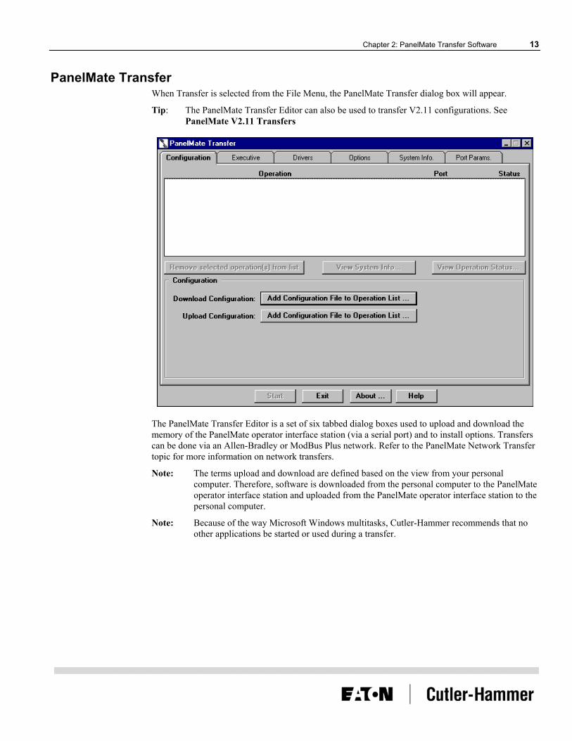
PanelMate Transfer When Transfer is selected from the File Menu, the PanelMate Transfer dialog box will appear.
Tip: The PanelMate Transfer Editor can also be used to transfer V2.11 configurations. See PanelMate V2.11 Transfers
The PanelMate Transfer Editor is a set of six tabbed dialog boxes used to upload and download the memory of the PanelMate operator interface station (via a serial port) and to install options. Transfers can be done via an Allen-Bradley or ModBus Plus network. Refer to the PanelMate Network Transfer topic for more information on network transfers.
Note: The terms upload and download are defined based on the view from your personal computer. Therefore, software is downloaded from the personal computer to the PanelMate operator interface station and uploaded from the PanelMate operator interface station to the personal computer.
Note: Because of the way Microsoft Windows multitasks, Cutler-Hammer recommends that no other applications be started or used during a transfer.

14 PanelMate Transfer Utility User’s Guide
PanelMate Network Transfers The Transfer Utility supports transfers to an operator interface station via a supported PLC communications network. Supported networks include:
• Allen Bradley Data Highway • Allen-Bradley Data Highway Plus • Allen Bradley Remote I/O Link • Modicon Modbus Plus
To use remote network transfers, you must purchase and install:
• The Remote Transfer Option from Cutler-Hammer • The appropriate communications card/device for your PC
• Allen-Bradley networks A-B 1784-KT ISA card
A-B 1784 PCMK ISA card
SST (S-S Technologies) 5136-SD ISA card
A-B KE/KF serial port module
• Modicon Modbus Plus network Modicon SA85 card
• Allen-Bradley Interchange or RSLinx software if you are using Allen-Bradley devices.
Note: RS Linx Lite Software is not sufficient. A full version of RS Linx is required.
PanelMate (V2.11) Transfer For PanelMate Series (common platform) units: to download PanelMate V2.11 Executive Firmware or communication drivers to a PanelMate Series 2000, PanelMate Series 3000, or PanelMate Series 4000, you must make the following changes to the pmconfig.ini file. [Note: The V2.11 Executive Firmware and communication driver files are supplied with the V2.11 software (not with the PanelMate Power Series or PanelMate Power Pro Software).]
Note: <path> is the file’s path on the personal computer.
1. In the [Executive Firmware List] section, add the following line:
seg1 = <path>\V2_110_1.exf
This line will allow the V2.11Executive Firmware to be selected in the PanelMate Transfer - Executive Tab dialog box.
2. In the [Executive Firmware List] section, add a line for each network driver to be downloaded. For example:
abdh=<path>\abdh.net
abrem=<path>\abrem.net
These lines will allow the V2.11 network drivers to be selected in the PanelMate Transfer - Executive Tab dialog box. For a complete list of network drivers, refer to the PanelMate V2.11 drivers topic.

Chapter 2: PanelMate Transfer Software 15
3. In the [Drivers List] section, add a line for each communication driver to be downloaded. For example: abdh=<path>\abdh.drv
abrem=<path>\abrem.drv
These lines will allow the V2.11communication drivers to be selected in the PanelMate Transfer - Driver Tab dialog box. For a complete list of communication drivers, refer to the PanelMate V2.11drivers topic.
Note: Network transfers to PanelMate Series 2000, PanelMate Series 3000, and PanelMate Series 4000 are supported. The V2.11 Executive Firmware or V2.11 communication drivers cannot be loaded onto PanelMate Power Series or PanelMate Power Pro units.
PanelMate Series V2.11 Drivers List Network Drivers
ABDH.NET Allen-Bradley Data Highway/Data Highway Plus
ABREM.NET Allen-Bradley Remote I/O
Communication Drivers AB.DRV Allen-Bradley Serial
ABDH485.DRV
Allen-Bradley Data Highway 485
ABDH.DRV Allen-Bradley Data Highway
ABDH.DRV Allen-Bradley Data Highway Plus
ABREM.DRV Allen-Bradley Remote I/O
CSITOL.DRV Custom Serial Interface
EATON.DRV Eaton
GE.DRV General Electric Peer-to-Peer
GE.DRV General Electric Master/Slave
GES90P.DRV General Electric Series 90 Point-to-Point
GES90.DRV General Electric Series 90 Network
GENERIC.DRV
Generic Protocol
MITS.DRV Mitsubishi
MITSFX.DRV Mitsubishi FX Series
MODICON.DRV
Modicon ASCII
MODRTU.DRV
Modicon RTU
MRTUE.DRV Modicon RTU
MODA.DRV Modicon A Series

16 PanelMate Transfer Utility User’s Guide
OMRON.DRV Omron Host Link
RELIANCE.DRV
Reliance
SIEMENS.DRV
Siemens
SQUARED.DRV
Square D
TI.DRV Texas Instruments
TIHL.DRV Texas Instruments Hostlink Peer-to-Peer
TIHL.DRV Texas Instruments Hostlink Master/Slave
TOSHT2.DRV
Toshiba T2
WEST.DRV Westinghouse
Note: The CSI and Allen-Bradley Data Highway 485 drivers require option diskettes which are purchased separately and must be installed in the PanelMate Series 2000, PanelMate Series 3000 and PanelMate Series 4000 before the driver can be downloaded.
Note: The Modicon RTU Enhanced driver (MRTUE.DRV) used a 750 millisecond timeout versus the Modicon RTU driver (MODRTU.DRV) which uses a 3 second timeout. (Timeout refers to the length of time the PanelMate operator interface station will wait to issue another request when a response was not received form the PLC.)
Chapter 2: PanelMate Transfer Software 17
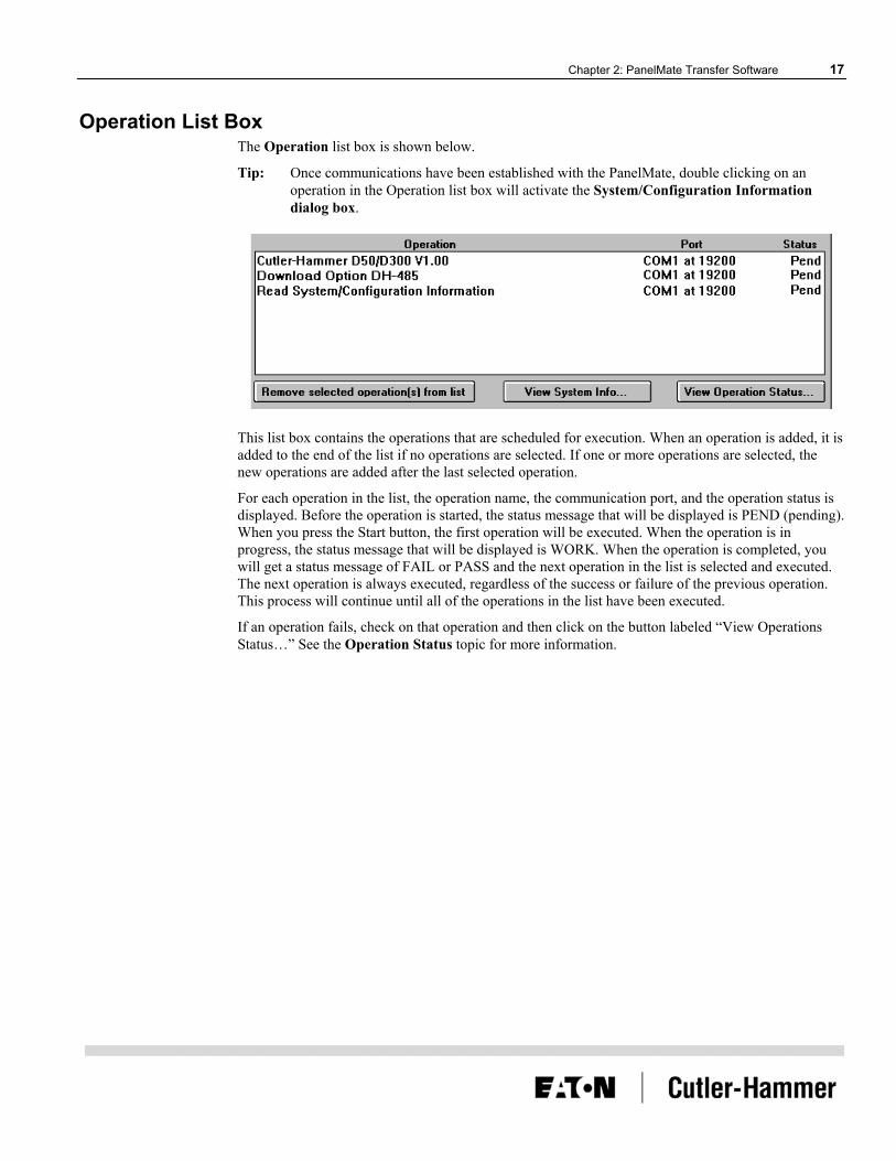
Operation List Box The Operation list box is shown below.
Tip: Once communications have been established with the PanelMate, double clicking on an operation in the Operation list box will activate the System/Configuration Information dialog box.
This list box contains the operations that are scheduled for execution. When an operation is added, it is added to the end of the list if no operations are selected. If one or more operations are selected, the new operations are added after the last selected operation.
For each operation in the list, the operation name, the communication port, and the operation status is displayed. Before the operation is started, the status message that will be displayed is PEND (pending). When you press the Start button, the first operation will be executed. When the operation is in progress, the status message that will be displayed is WORK. When the operation is completed, you will get a status message of FAIL or PASS and the next operation in the list is selected and executed. The next operation is always executed, regardless of the success or failure of the previous operation. This process will continue until all of the operations in the list have been executed.
If an operation fails, check on that operation and then click on the button labeled “View Operations Status…” See the Operation Status topic for more information.

18 PanelMate Transfer Utility User’s Guide
There are three buttons associated with the Operation list box. The buttons are described below.
<Remove selected operation(s) from list>: Removes the selected operation from the Operation list box.
<View System Info>: Displays the System/Configuration Information dialog box with data from the currently selected operation.
<View Operation Status>: Displays the Operation Status dialog box with data from the currently selected operation.
System/Configuration Information When the View System Info button is pressed, the System/Configuration Information dialog box will appear.
The System/Configuration Information dialog box displays the configuration information from the PanelMate operator interface station following the last operation and displays the version of the Executive Firmware, options, and drivers loaded in the PanelMate operator interface station
The Save button allows you to save the System/Configuration Information to an ASCII text file.

Chapter 2: PanelMate Transfer Software 19
Operation Status When the View Operation Status button is pressed, the Operation Status dialog box will appear.
The Operation Status dialog box contains a list box of errors and/or status messages associated with a particular operation. Some of the errors or messages are about failed operations, while other errors or messages contain helpful information about successful operations. A status (Fail, Pend, or Pass) of the operation is also displayed.
The Save button allows you to save the errors or messages to an ASCII file.

20 PanelMate Transfer Utility User’s Guide
PanelMate Transfer - Configuration Tab The PanelMate Transfer - Configuration Tab dialog box is shown below.
Note: The above figure shows a PanelMate configuration in the Operation list box.
The PanelMate Transfer - Configuration Tab dialog box allows you to upload and download configurations. The configurations to be transferred will be displayed in the Operation list box. (The filename extension will vary depending on the PanelMate operator interface station.) The configuration name and the filename used to export the configuration will be displayed in the Operation list box.
The fields in the PanelMate Transfer - Configuration Tab dialog box are described below:
<Remove selected operation(s) from list>: Removes the selected operation from the Operation list box.
<View System Info>: Displays the System/Configuration Information dialog box with data from the currently selected operation.
<View Operation Status>: Displays the Operation Status dialog box with data from the currently selected operation.
Download Configuration: Allows you to download a configuration from the development computer to the PanelMate operator interface station The configuration will include system parameters, PLC connection information and display pages containing templates, elements, and static text. When you press the Add Configuration File to Operation List button, the Download Configuration dialog box will appear.

Chapter 2: PanelMate Transfer Software 21
Note: Before downloading a configuration, you must export the configuration. For additional information on exporting configurations, refer to the Export topic in the PanelMate online help.
Upload Configuration: Allows you to upload a configuration from the PanelMate operator interface station to the development computer and store it. When you press the Add Configuration File to Operation List button, the Upload Configuration dialog box will appear.
<Start>: Allows you to begin executing the first operation in the Operation list box.
<Exit>: Allows you to exit the PanelMate Transfer dialog box.
<About>: Displays the About PanelMate Transfer dialog box.
Download Configuration Note: When downloading a configuration to a different model of PanelMate, you must first
convert the configuration to the appropriate PanelMate model using the configuration software.
When the Add Configuration File to Operation List button (next to the Download Configuration field) is pressed on the PanelMate Transfer - Configuration Tab dialog box, the Download Configuration dialog box will appear.
Note: In the above figure, the .XXX designates the filename extension. The filename extension will vary depending on the PanelMate operator interface station (.pps for PanelMate Power Series and PanelMate Power Pro).
The PanelMate operator interface station must be loaded with Executive Firmware and necessary drivers and options before it can receive a configuration.
In the Download Configuration dialog box, select the type of file you want to download, the name of the file to download, and the directory for your file.
When downloading a configuration containing an option, the transfer software will check to ensure that the option is installed. If the option is not installed, an error will be generated.

22 PanelMate Transfer Utility User’s Guide
Upload Configuration When the Add Configuration File to Operation List button (next to the Upload Configuration field) is pressed on the PanelMate Transfer - Configuration Tab dialog box, the Upload Configuration dialog box will appear.
Note: In the above figure, the .XXX designates the filename extension. The filename extension will vary depending on the PanelMate operator interface station.
In the Upload Configuration dialog box, select the type of file you want to upload, the name of the file to upload, and the directory for your file.
CAUTION: If an existing file is selected in the Operation list box, its contents will be overwritten with the configuration file being uploaded.

Chapter 2: PanelMate Transfer Software 23
PanelMate Transfer - Executive Tab Note: Once version 3.01 or higher Executive Firmware has been loaded onto your PanelMate
operator interface station, you will be unable to overwrite it with an older (version 3.0 or earlier) load of Executive Firmware.
The PanelMate Transfer - Executive Tab dialog box is shown below.
The Executive tab allows you to download Executive Firmware and network drivers. An online system must contain Executive Firmware before it can execute a configuration.
Note: Make sure that the Executive Firmware matches the target PanelMate model. If you wish to download PanelMate Series V2.11 Executive Firmware, refer to the PanelMate Series (V2.11) Transfer topic.
The fields in the PanelMate Transfer - Executive Tab dialog box are described below:
<Remove selected operation(s) from list>: Removes the selected operation from the Operation list box.
<View System Info>: Displays the System/Configuration Information dialog box with data from the currently selected operation.
<View Operation Status>: Displays the Operation Status dialog box with data from the currently selected operation.

24 PanelMate Transfer Utility User’s Guide
Executive Firmware: Allows you to select and display the Executive Firmware to be downloaded.
Note: All drivers previously loaded on the PanelMate operator interface station will be removed. You must re-download the appropriate drivers after the Executive Firmware has been downloaded.
Network Driver: Allows you to select and display the network driver to be downloaded with the Executive Firmware.
<Add to Operation List>: Adds the selected Executive Firmware and/or network driver to the Operation list box to be downloaded.
<Start>: Allows you to begin executing the first operation in the Operation list box.
<Exit>: Allows you to exit the PanelMate Transfer dialog box.
<About>: Displays the About PanelMate Transfer dialog box.
PanelMate Transfer - Driver Tab The PanelMate Transfer - Driver Tab dialog box is shown below.
The Driver tab allows you to transfer a communication driver from the development computer to the PanelMate operator interface station. An online system must contain this driver to communicate to an outside device, such as a PLC. The driver to be downloaded will be displayed in the Operation list box.

Chapter 2: PanelMate Transfer Software 25
The fields in the PanelMate Transfer - Driver Tab dialog box are described below:
<Remove selected operation(s) from list>: Removes the selected operation from the Operation list box.
<View System Info>: Displays the System/Configuration Information dialog box with data from the currently selected operation.
<View Operation Status>: Displays the Operation Status dialog box with data from the currently selected operation.
Communication Driver: Allows you to select and display the communication driver to be downloaded.
<Add to Operation List>: Adds the selected driver to the Operation list box to be downloaded.
<Start>: Allows you to begin executing the first operation in the Operation list box.
<Exit>: Allows you to exit the PanelMate Transfer dialog box.
<About>: Displays the About PanelMate Transfer dialog box.
PanelMate Transfer - Options Tab The PanelMate Transfer - Options Tab dialog box is shown below.

26 PanelMate Transfer Utility User’s Guide
The Options tab allows you to transfer an option from your development computer’s floppy disk or hardware key to the PanelMate operator interface station. The option to be downloaded will be displayed in the Operation list box.
Note: When downloading a configuration containing an option, the transfer software will check to ensure that the option is installed. If the option is not installed, an error will be generated.
The fields in the PanelMate Transfer - Options Tab dialog box are described below:
<Remove selected operation(s) from list>: Removes the selected operation from the Operation list box.
<View System Info>: Displays the System/Configuration Information dialog box with data from the currently selected operation.
<View Operation Status>: Displays the Operation Status dialog box with data from the currently selected operation.
<Option Source>: If “A” is selected on Option Source Location, displays the Option Diskette Verification dialog box when the Validate button is pressed. If “Hardware Key” is selected, displays the Hardware Key Validation dialog box when the Validate button is pressed.
<Option Source Location>: Allows you to select either drive letter A to locate your option diskette, or, Hardware Key to locate your hardware key. Note: You should always press the Validate button before installing an option to check the remaining number of installations.
<Add to Operation List>: Adds the option to the Operation list box to be downloaded.
<Start>: Allows you to begin executing the first operation in the Operation list box.
<Exit>: Allows you to exit the PanelMate Transfer dialog box.
<About>: Displays the About PanelMate Transfer dialog box.
An additional PanelMate Transfer – Options Tab dialog box is shown below.

Chapter 2: PanelMate Transfer Software 27
When Option Source Location “Hardware Key” is selected, an additional field appears, I/O References to Install. Note: This feature is applicable only for use with PanelMate Pro LT 1100 units. The following section describes how to download additional I/O References to the PanelMate Pro LT 1100.
Download Additional I/O References to the PanelMate Pro LT 1100 First, install the hardware key, which is included in the I/O Reference Point Expansion Option Kit, into the parallel port of the PC. Then, determine the current number of installed references on the PanelMate Pro LT 1100 by using either of the following two methods:
(1) PanelMate Power Pro LT 1100 should be in Transfer Mode. On the PC, using the Transfer Utility, Select the System Info. tab. Select the System/Configuration Info. button. Select Start (status should change to Pass). Double-click on Read System/Configuration Information line. Displayed under Executive Firmware, Model are the number of pages, and number of I/O references contained on the unit. The maximum number of references allowed per unit is 512; i.e., if the unit is at 64, as many as 448 additional references (7 upgrades) may be added to get to the maximum 512.
(2) On the PanelMate Pro LT 1100, from Offline Mode, select Display System/Config. Information, select Execute. The current number of installed I/O references appears next to Model. Or, in Run Mode, from any page, select Get Page, select More, select Set up Page, select Display System/Config. Information, select Execute.
To Download Additional I/O References CAUTION: I/O Reference upgrades are permanent. Once an upgrade is installed (downloaded) on a PanelMate Pro LT 1100, it cannot be uploaded back to the hardware key. Make sure the I/O references to install are set correctly before starting the installation. Note: Be sure to select the number of additional reference points you wish to install. Example: If your unit currently has 64 references installed, and you wish the new total of reference points to be 192, you will select 128 additional references to install.
The target PanelMate Pro LT 1100 needs to be set to either Serial Transfer Mode or Network Transfer Mode. To download additional I/O references, click on the arrow next to I/O References to Install, and select the desired number. Click on Add to Operation List, then click on Start. Status should change from Pend to Pass. Double click on the status line to view the number of references installed on the unit.
If the operation fails, highlight the operation line, select View Operation Status, and a message will appear stating the reason for the failed operation. Common reasons for failure include selecting more
28 PanelMate Transfer Utility User’s Guide
than the maximum number of I/O References permitted to be installed on the unit, or selecting more references than the hardware key has available.
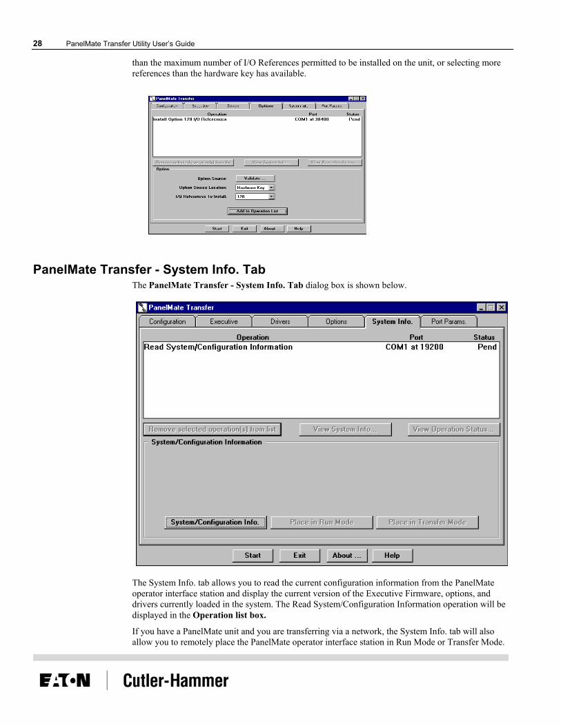
PanelMate Transfer - System Info. Tab The PanelMate Transfer - System Info. Tab dialog box is shown below.
The System Info. tab allows you to read the current configuration information from the PanelMate operator interface station and display the current version of the Executive Firmware, options, and drivers currently loaded in the system. The Read System/Configuration Information operation will be displayed in the Operation list box.
If you have a PanelMate unit and you are transferring via a network, the System Info. tab will also allow you to remotely place the PanelMate operator interface station in Run Mode or Transfer Mode.

Chapter 2: PanelMate Transfer Software 29
The fields in the PanelMate Transfer - System Info. Tab dialog box are described below:
<Remove selected operation(s) from list>: Removes the selected operation from the Operation list box.
<View System Info>: Displays the System/Configuration Information dialog box with data from the currently selected operation.
<View Operation Status>: Displays the Operation Status dialog box with data from the currently selected operation.
<System/Configuration Info.>: Adds the Read System/Configuration Information operation to the Operation list box.
<Place in Run Mode>: Allows you to remotely place the PanelMate operator interface station in Run Mode if a network device is selected in the Port Device field in the PanelMate Transfer - Port Params. Tab dialog box. Note that the Remote Transfer option MUST be installed and the Remote Mode Change field must be configured as IMMEDIATE, DEFAULT, or ACCEPT in the System Parameters - Remote Tab dialog box before you attempt to remotely place the PanelMate operator interface station in Run Mode.
If a serial communication port (i.e., COM1 or COM2) is selected in the Port Device field in the PanelMate Transfer - Port Params. Tab dialog box, the button will not be selectable.
For more information about the Place in Run Mode selection, refer to the Remote Mode Change section in the System Parameters topic in the PanelMate online help.
<Place in Transfer Mode>: Allows you to remotely place the PanelMate operator interface station in Transfer Mode if a network device is selected in the Port Device field in the PanelMate Transfer - Port Params. Tab dialog box. Note that the Remote Transfer option MUST be installed and the Remote Mode Change field must be configured as IMMEDIATE, DEFAULT, or ACCEPT in the System Parameters - Remote Tab dialog box before you attempt to remotely place the PanelMate operator interface station in Transfer Mode.
If a serial communication port (i.e., COM1 or COM2) is selected in the Port Device field in the PanelMate Transfer - Port Params. Tab dialog box, the button will not be selectable.
For more information about the Place in Transfer Mode selection, refer to the Remote Mode Change section in the System Parameters topic in the PanelMate online help.
<Start>: Allows you to begin executing the first operation in the Operation list box.
<Exit>: Allows you to exit the PanelMate Transfer dialog box.
<About>: Displays the About PanelMate Transfer dialog box.
30 PanelMate Transfer Utility User’s Guide
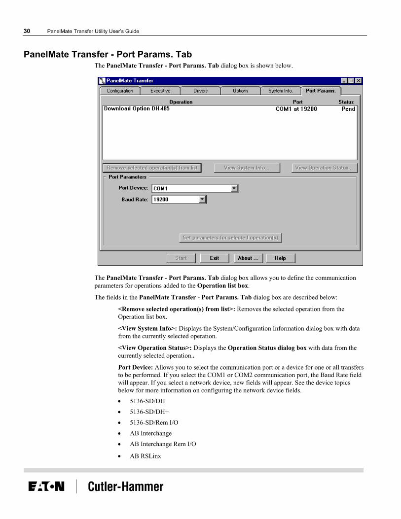
PanelMate Transfer - Port Params. Tab The PanelMate Transfer - Port Params. Tab dialog box is shown below.
The PanelMate Transfer - Port Params. Tab dialog box allows you to define the communication parameters for operations added to the Operation list box.
The fields in the PanelMate Transfer - Port Params. Tab dialog box are described below:
<Remove selected operation(s) from list>: Removes the selected operation from the Operation list box.
<View System Info>: Displays the System/Configuration Information dialog box with data from the currently selected operation.
<View Operation Status>: Displays the Operation Status dialog box with data from the currently selected operation..
Port Device: Allows you to select the communication port or a device for one or all transfers to be performed. If you select the COM1 or COM2 communication port, the Baud Rate field will appear. If you select a network device, new fields will appear. See the device topics below for more information on configuring the network device fields. • 5136-SD/DH • 5136-SD/DH+ • 5136-SD/Rem I/O • AB Interchange • AB Interchange Rem I/O
• AB RSLinx

Chapter 2: PanelMate Transfer Software 31
• AB RSLinx Rem I/O
• MB Plus
Baud Rate: Allows you to select the baud rate for one or all transfers to be performed. Note that the Baud Rate field will only appear if you configured the Port Device field as COM1 or COM2.
<Set parameters for selected operation(s)>: Allows you to define different communication parameters for each selected operation.
Note: You cannot change network communication parameters to serial (COM1 or COM2) communication parameters for the Place in Run Mode and Place in Transfer Mode operations.
<Start>: Allows you to begin executing the first operation in the Operation list box.
<Exit>: Allows you to exit the PanelMate Transfer dialog box.
<About>: Displays the About PanelMate Transfer dialog box.
5136-SD/DH If you select 5136-SD/DH in the Port Device field, the following Port Parameters screen will appear.
The fields in the Port Parameters screen are described below.
Local Address: Sets the PC address on the chosen network.
Remote Address: Sets the remote address of the PanelMate operator interface station to transfer to.
Terminal Name: Defines a “Who Active” name for the PC on the network.
Card: Defines the port address, interrupt number, memory address, and memory size for the 5136-SD2 card.
Port: Sets the card’s PC port address.
IRQ: Sets the card’s PC Interrupt.
Base Address: Sets the card’s PC memory address.
Memory Size: Indicates the amount of PC memory the card will use.
32 PanelMate Transfer Utility User’s Guide
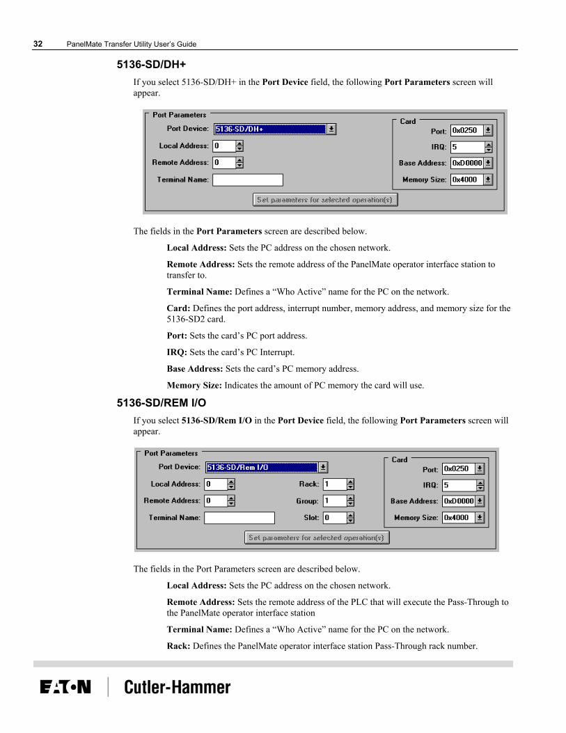
5136-SD/DH+ If you select 5136-SD/DH+ in the Port Device field, the following Port Parameters screen will appear.
The fields in the Port Parameters screen are described below.
Local Address: Sets the PC address on the chosen network.
Remote Address: Sets the remote address of the PanelMate operator interface station to transfer to.
Terminal Name: Defines a “Who Active” name for the PC on the network.
Card: Defines the port address, interrupt number, memory address, and memory size for the 5136-SD2 card.
Port: Sets the card’s PC port address.
IRQ: Sets the card’s PC Interrupt.
Base Address: Sets the card’s PC memory address.
Memory Size: Indicates the amount of PC memory the card will use.
5136-SD/REM I/O If you select 5136-SD/Rem I/O in the Port Device field, the following Port Parameters screen will appear.
The fields in the Port Parameters screen are described below.
Local Address: Sets the PC address on the chosen network.
Remote Address: Sets the remote address of the PLC that will execute the Pass-Through to the PanelMate operator interface station
Terminal Name: Defines a “Who Active” name for the PC on the network.
Rack: Defines the PanelMate operator interface station Pass-Through rack number.

Chapter 2: PanelMate Transfer Software 33
Group: Defines the PanelMate operator interface station Pass-Through group number within the rack.
Slot: Defines the PanelMate operator interface station Pass-Through slot number within the group.
Card: Defines the port address, interrupt number, memory address, and memory size for the 5136-SD2 card.
Port: Sets the card’s PC port address.
IRQ: Sets the card’s Interrupt.
Base Address: Sets the card’s PC memory address.
Memory Size: Indicates the amount of PC memory the card will use.
AB Interchange If you select AB Interchange in the Port Device field, the following Port Parameters screen will appear.
The fields in the Port Parameters screen are described below.
Remote Address: Sets the remote address of the PanelMate operator interface station to transfer to.
Push Wheel: Selects a Push Wheel Value from the AB Interchange CFG_KT.INI file. This value must range from 1 to 8 and equal an active device started by the Interchange software.
AB Interchange Rem I/O If you select AB Interchange Rem I/O in the Port Device field, the following Port Parameters screen will appear.

34 PanelMate Transfer Utility User’s Guide
The fields in the Port Parameters screen are described below.
Remote Address: Sets the remote address of the PLC that will execute the Pass-Through to the PanelMate operator interface station
Push Wheel: Selects a Push Wheel Value from the AB Interchange CFG_KT.INI file. This value must range from 1 to 8 and equal an active device started by the Interchange software.
Rack: Defines the PanelMate operator interface station Pass-Through rack number.
Group: Defines the PanelMate operator interface station Pass-Through group number within the rack.
Slot: Defines the PanelMate operator interface station Pass-Through slot number within the group.
AB RSLinx If you select AB RSLinx in the Port Device field, the following Port Parameters screen will appear.
The fields in the Port Parameters screen are described below.
Remote Address: Sets the remote address of the PanelMate operator interface station to transfer to.
Driver Name: Identifies the network card recognized by the AB RSLinx software.
AB RSLinx Rem I/O If you select AB RSLinx Rem I/O in the Port Device field, the following Port Parameters screen will appear.
Chapter 2: PanelMate Transfer Software 35
The fields in the Port Parameters screen are described below.
Remote Address: Sets the remote address of the PLC that will execute the Pass-Through to the PanelMate operator interface station
Driver Name: Identifies the network card recognized by the AB RSLinx software
Rack: Defines the PanelMate operator interface station Pass-Through rack number.
Group: Defines the PanelMate operator interface station Pass-Through group number within the rack.
Slot: Defines the PanelMate operator interface station Pass-Through slot number within the group.
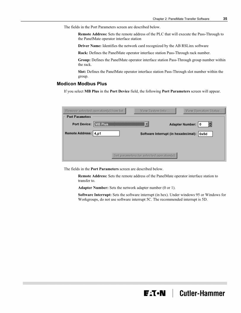
Modicon Modbus Plus If you select MB Plus in the Port Device field, the following Port Parameters screen will appear.
The fields in the Port Parameters screen are described below.
Remote Address: Sets the remote address of the PanelMate operator interface station to transfer to.
Adapter Number: Sets the network adapter number (0 or 1).
Software Interrupt: Sets the software interrupt (in hex). Under windows 95 or Windows for Workgroups, do not use software interrupt 5C. The recommended interrupt is 5D.

36 PanelMate Transfer Utility User’s Guide
Network Transfer Troubleshooting
3
This chapter provides guidance on common problems associated with network transfers. Specifically, this chapter covers.
• Troubleshooting tips
• Network transfer errors
Chapter 3: Network Transfer Troubleshooting 37
Network Transfer Troubleshooting Tips In the [386Enh] section of your Windows SYSTEM.INI file you may need to add a EMMExclude statement to prevent Windows from using the memory area being used by 5136-SD, or 1784-KT, or 1784-PCMK cards.
For example: EMMExclude=CC00-CCFF
Under Windows Control Panel, 386 Enhanced, the Exclusive in Foreground checkbox must not be checked. This will cause the transfers to not work.
If the standard Windows serial transfers are not working and you are receiving a “No 8250 present” error after you have installed the A-B Interchange DF1 software, you will need to re-mark out the DEVICE=VDF1.386, COMxIRQy, and COMxVDFx lines that you set up for the Interchange DF1 software in the [386Enh] section of the SYSTEM.INI
Network Transfer Errors The following tables list the possible errors that you can receive when attempting to perform a network transfer to a PanelMate operator station. The possible causes and solutions are also listed.
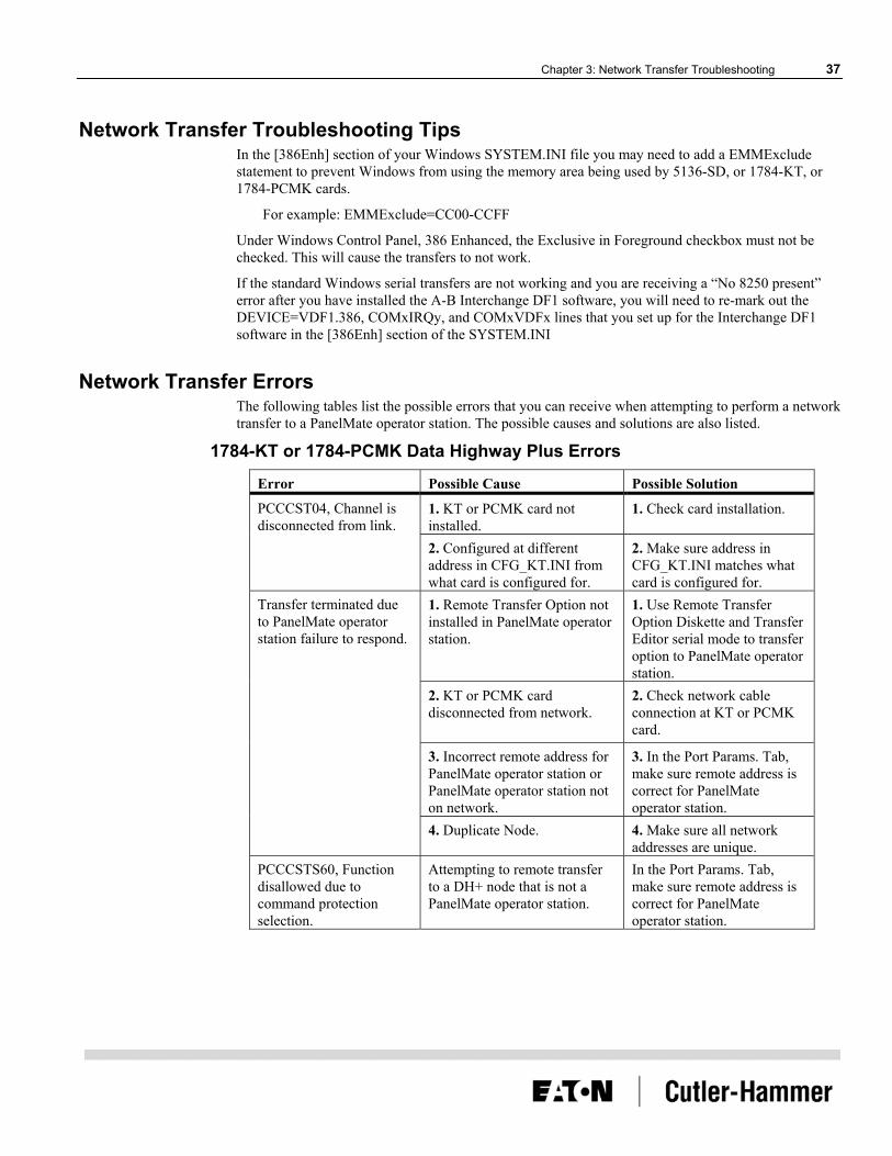
1784-KT or 1784-PCMK Data Highway Plus Errors
Error Possible Cause Possible Solution
1. KT or PCMK card not installed.
1. Check card installation. PCCCST04, Channel is disconnected from link.
2. Configured at different address in CFG_KT.INI from what card is configured for.
2. Make sure address in CFG_KT.INI matches what card is configured for.
1. Remote Transfer Option not installed in PanelMate operator station.
1. Use Remote Transfer Option Diskette and Transfer Editor serial mode to transfer option to PanelMate operator station.
2. KT or PCMK card disconnected from network.
2. Check network cable connection at KT or PCMK card.
3. Incorrect remote address for PanelMate operator station or PanelMate operator station not on network.
3. In the Port Params. Tab, make sure remote address is correct for PanelMate operator station.
Transfer terminated due to PanelMate operator station failure to respond.
4. Duplicate Node. 4. Make sure all network addresses are unique.
PCCCSTS60, Function disallowed due to command protection selection.
Attempting to remote transfer to a DH+ node that is not a PanelMate operator station.
In the Port Params. Tab, make sure remote address is correct for PanelMate operator station.
38 PanelMate Transfer Utility User’s Guide
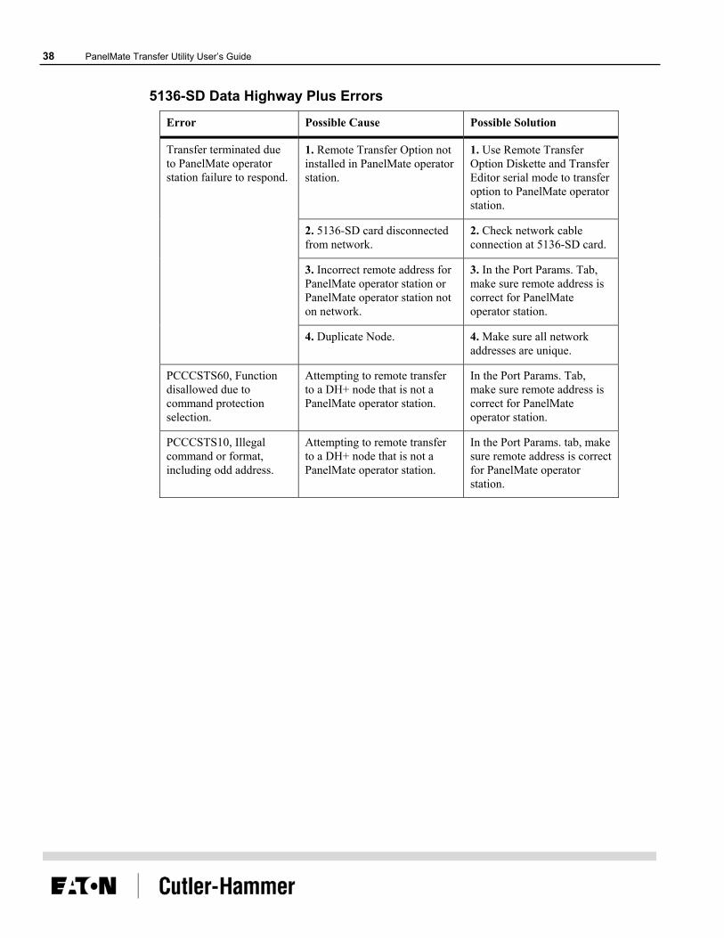
5136-SD Data Highway Plus Errors
Error Possible Cause Possible Solution
1. Remote Transfer Option not installed in PanelMate operator station.
1. Use Remote Transfer Option Diskette and Transfer Editor serial mode to transfer option to PanelMate operator station.
2. 5136-SD card disconnected from network.
2. Check network cable connection at 5136-SD card.
3. Incorrect remote address for PanelMate operator station or PanelMate operator station not on network.
3. In the Port Params. Tab, make sure remote address is correct for PanelMate operator station.
Transfer terminated due to PanelMate operator station failure to respond.
4. Duplicate Node. 4. Make sure all network addresses are unique.
PCCCSTS60, Function disallowed due to command protection selection.
Attempting to remote transfer to a DH+ node that is not a PanelMate operator station.
In the Port Params. Tab, make sure remote address is correct for PanelMate operator station.
PCCCSTS10, Illegal command or format, including odd address.
Attempting to remote transfer to a DH+ node that is not a PanelMate operator station.
In the Port Params. tab, make sure remote address is correct for PanelMate operator station.

Chapter 3: Network Transfer Troubleshooting 39
KF2 Module Data Highway Plus Errors
Error Possible Cause Possible Solution
1. Remote Transfer Option not installed in PanelMate operator station.
1. Use Remote Transfer Option Diskette and Transfer Editor serial mode to transfer option to PanelMate operator station.
2. Baud rate in CFG_KT.INI for KF2 is incorrect.
2. Correct to match baud rate used on KF2.
3. KF2 disconnected from network.
3. Check network cable connection at KF2.
4. Incorrect remote address for PanelMate operator station.
4. In the Port Params. Tab, make sure remote address is correct for PanelMate operator station.
Transfer terminated due to PanelMate operator station failure to respond.
5. Duplicate Node. 5. Make sure all network addresses are unique.
PCCCSTS60, Function disallowed due to command protection selection.
Attempting to remote transfer to a DH+ node that is not a PanelMate operator station.
In the Port Params. Tab, make sure remote address is correct for PanelMate operator station.
PCCCSTS10, Illegal command or format, including odd address.
Attempting to remote transfer to a DH+ node that is not a PanelMate operator station.
In the Port Params. Tab, make sure remote address is correct for PanelMate operator station.
40 PanelMate Transfer Utility User’s Guide
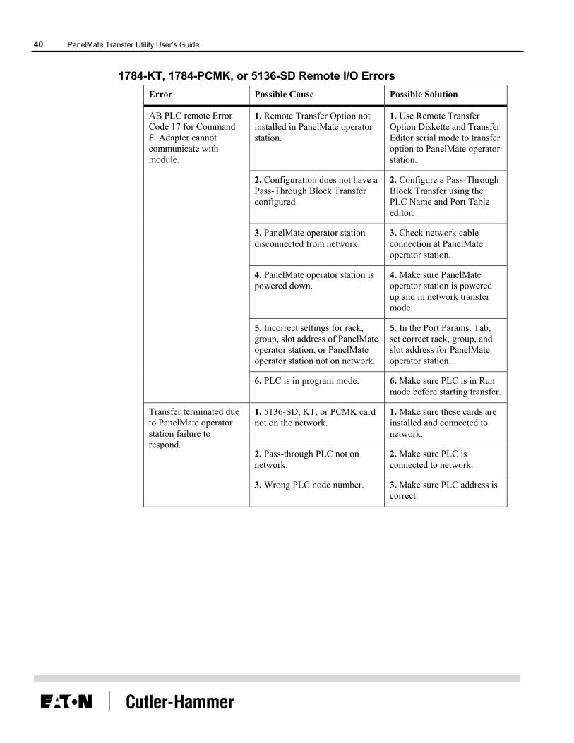
1784-KT, 1784-PCMK, or 5136-SD Remote I/O Errors Error Possible Cause Possible Solution
1. Remote Transfer Option not installed in PanelMate operator station.
1. Use Remote Transfer Option Diskette and Transfer Editor serial mode to transfer option to PanelMate operator station.
2. Configuration does not have a Pass-Through Block Transfer configured
2. Configure a Pass-Through Block Transfer using the PLC Name and Port Table editor.
3. PanelMate operator station disconnected from network.
3. Check network cable connection at PanelMate operator station.
4. PanelMate operator station is powered down.
4. Make sure PanelMate operator station is powered up and in network transfer mode.
5. Incorrect settings for rack, group, slot address of PanelMate operator station, or PanelMate operator station not on network.
5. In the Port Params. Tab, set correct rack, group, and slot address for PanelMate operator station.
AB PLC remote Error Code 17 for Command F. Adapter cannot communicate with module.
6. PLC is in program mode. 6. Make sure PLC is in Run mode before starting transfer.
1. 5136-SD, KT, or PCMK card not on the network.
1. Make sure these cards are installed and connected to network.
2. Pass-through PLC not on network.
2. Make sure PLC is connected to network.
Transfer terminated due to PanelMate operator station failure to respond.
3. Wrong PLC node number. 3. Make sure PLC address is correct.

Chapter 3: Network Transfer Troubleshooting 41
Modbus Plus Errors When there are problems transferring information via a Modicon Modbus Plus network, two types of errors may occur.
• Port Parameters Errors are caused by an incorrectly formatted Remote Address.
• NetBIOS Errors are returned by the NetBIOS.
Port Parameter Errors These error messages are caused by an incorrectly formated Remote Address. To eliminate these errors, correctly re-format the Remote Address.
Error MODBUS Plus device error. This interrupt must be in the range 0x0 to 0xFF. MODBUS Plus device error. The remote address is blank. MODBUS Plus device error. The remote address has missing node. MODBUS Plus device error. The remote address has slave path out of position. MODBUS Plus device error. The remote address has a bad character. MODBUS Plus device error. The remote address has too many nodes. MODBUS Plus device error. The remote address has a node out of range. MODBUS Plus device error. The remote address has slave path out of range.

42 PanelMate Transfer Utility User’s Guide
NetBIOS Errors These error messages are returned by the NetBIOS. Consult a network specialist or a textbook on NetBIOS programming.
Error MODBUS Plus NetBIOS driver is not loaded at software interrupt %1. MODBUS Plus NetBIOS error. No Network Control Blocks available. MODBUS Plus NetBIOS error. Bad send or status buffer size. MODBUS Plus NetBIOS error. Invalid NetBIOS command. MODBUS Plus NetBIOS error. Command time-out had expired. MODBUS Plus NetBIOS error. Receive buffer not large enough. MODBUS Plus NetBIOS error. Local session number is bad. MODBUS Plus NetBIOS error. Not enough memory for LAN card. MODBUS Plus NetBIOS error. The session has been closed. MODBUS Plus NetBIOS error. The command has been closed. MODBUS Plus NetBIOS error. Local name already exists. MODBUS Plus NetBIOS error. Local name table is full. MODBUS Plus NetBIOS error. Cannot delete name used in a session. MODBUS Plus NetBIOS error. Local session table is full. MODBUS Plus NetBIOS error. Remote station is not listening for call. MODBUS Plus NetBIOS error. Bad value in number field. MODBUS Plus NetBIOS error. No answer to CALL or no such remote. MODBUS Plus NetBIOS error. Name not in local name table. MODBUS Plus NetBIOS error. Name is used elsewhere on network. MODBUS Plus NetBIOS error. Name incorrectly deleted. MODBUS Plus NetBIOS error. Session aborted abnormally. MODBUS Plus NetBIOS error. Two or more identical names in use. MODBUS Plus NetBIOS error. Bad NetBIOS packet on network. MODBUS Plus NetBIOS error. Network card is busy. MODBUS Plus NetBIOS error. Too many NetBIOS commands queued. MODBUS Plus NetBIOS error. Bad adapter number. MODBUS Plus NetBIOS error. Command finished while canceling. MODBUS Plus NetBIOS error. Command cannot be cancelled. MODBUS Plus NetBIOS error. Unknown error code. MODBUS Plus NetBIOS did not respond to open command within allotted time.

Chapter 3: Network Transfer Troubleshooting 43
Transfer Problems Some common transfer utility problems and solutions are listed below.
Note: For information on configuration editor or online problems, refer to the PanelMate Configuration Editor User’s Guide or the PanelMate Online Operation User’s Guide.
Problem: Failure transferring at 38400 baud rate
Possible Cause: 1) Baud rate is too high for the hardware
Corrective Action: Lower the baud rate (19200 or 9600) and transfer again
Possible Cause: 2) COM port is defective or needs updated
Corrective Action: Try a different COM port
Problem: Using the PanelMate Transfer Editor to download driver versions prior to V211; the driver was successfully downloaded but a FAILED status was reported.
Corrective Action: Check the PanelMate operator station to see if the driver was loaded. Display System Configuration Information from the Setup Page or Offline Mode.
Problem: The Transfer Editor does not transfer PanelMate Compact software (version 1.14) to a PanelMate Compact unit.
Corrective Action: The Transfer Editor does not support this type of transfer.
Problem: Online Communications fail if the transfer cable is connected to the RS232 port of the PanelMate Series 1500 and RS422 communications are attempted in Run Mode.
Possible Cause: WARNING - only one connection may be used at a time. If both connections are used simultaneously, communication errors will result which may cause hazardous conditions when communicating with a PLC.
Problem: Using Windows 3.1X, problems encountered with serial transfers at high baud rates using existing drivers.
Possible Cause: 1)Baud rate too high for the hardware.
Corrective Action: Lower the baud rate.
Possible Cause: 2) Updated serial drivers needed.
Corrective Action: Install the serial drivers in the system.ini file
Problem: The transfer terminated due to an “operator station failure to respond” to a “general error.”
Possible Cause: Another software program may be using the same serial port that the transfer utility is trying to use.
Corrective Action: Check to be sure that this is not the case. If it is happening, shut down that program and restart the transfer utility software.

44 PanelMate Transfer Utility User’s Guide
Problem: COM1 and COM2 do not appear as selections in the Port Device list of the PanelMate Transfer - Port Parameters Tab dialog box.
Possible Cause: No Windows serial device drivers are running.
Corrective Action: Enable a Windows serial virtual device driver by editing the 386 Enhanced section of the system.ini file. If the following line exists in this section:
;device=*vcd
then remove the semicolon from the line. If the line is not found, either add the line to this section (without the semicolon) or consult your personal computer manufacturer for the name of their standard serial virtual device driver and add it to the 386 Enhanced section. Save the file and restart Windows.
Problem: Transfers fail when the Transfer Editor window is minimized.
Possible Cause: A new Windows application does not give control to the Transfer Editor resulting in a timeout error.
Corrective Action: Start the transfer again after expanding the Transfer Editor window and do not minimize the Transfer Editor window until the transfer is completed successfully.
Problem: File Does Not Exist errors are reported when starting the Transfer Editor.
Possible Cause: Older versions of: PanelMate software, Executive Firmware, or PLC drivers have been deleted from this system.
Corrective Action: Remove the deleted Executive Firmware and drivers from the file pmconfig.ini in the Windows directory.
Installing Serial Drivers Note. The following instructions are for Windows 3.x or Windows for Workgroups 3.71
operating systems only: 1. In the [386 Enh] section of the system.ini file, disable the current default serial device-driver
entry
“device = *vcd” by placing a semicolon in front of this line.
2. Add two lines at the start of the [386 Enh] section: device=C:\WINDOWS\PMAPPS\gcl520\vxd\vgfcd.386 device=C:\WINDOWS\PMAPPS\gcl520\vxd\vgfd.386
3. Add two lines to the bottom of the [386 Enh] section: GFMaxDosComPorts=4 GFMaxDosBuffPages=1

Index 45
Index A
AB Interchange, 33 ABOUT THE PANELMATE TRANSFER, 7
C Configuration Tab, 20 CONFIGURATION TAB, 20 Configuring the Port Device: 5136-SD/DH, 31 Configuring the Port Device: 5136-SD/DH+, 32 Configuring the Port Device: 5136-SD/REM I/O, 32 Configuring the Port Device: AB Interchange, 33 Configuring the Port Device: AB Interchange Rem I/O, 33 Configuring the Port Device: AB RSLinx, 34 Configuring the Port Device: AB RSLinx Rem I/O, 34 Configuring the Port Device: MB Plus, 35
D Data Highway Plus Errors: 1784-KT OR 1784-PCMK Data
Highway Plus Errors, 37 Data Highway Plus Errors: 5136-SD Data Highway Plus
Errors, 38 Data Highway Plus Errors: KF2 Module Data Highway
Plus Errors, 39 Download Configuration, 21 DOWNLOAD CONFIGURATION, 21 Downloading Drivers to a PanelMate Unit, 8 Driver Tab, 24, 25
E Errors For Network Transfers, 37 Errors: 1784-KT
1784-PCMK or 5136-SD Remote I/O Errors, 40
Executive Tab, 23
I INSTALLING SERIAL DRIVERS, 44
M MEMORY, 12
Modbus Plus Errors, 41
N NeTBIOS Errors, 42 Network Transfer Errors, 37 Network Transfer Troubleshooting Tips, 37
O Operation List Box, 17 Operation Status, 19 Options Tab, 25, 26
P Panelmate Transfer - Configuration Tab, 20 Panelmate Transfer - Driver Tab, 24 Panelmate Transfer - Executive Tab, 23 Panelmate Transfer - Options Tab, 25 Panelmate Transfer - Port Params. Tab, 30 Panelmate Transfer - System Info. Tab, 28 Port Parameters Errors, 41 Port Params. Tab, 30 Problems With Transfer Software, 43
S Serial Transfer Cables, 8 System Info. Tab, 28, 29 System/Configuration Information, 18
T Transfer, 14 Transfer Editor, 13 TRANSFER MODE, 7 Transfer Problems, 43 TRANSFER STEPS, 10 TRANSFER UTILITY OVERVIEW, 6 Troubleshooting The Transfer Software, 43 Troubleshooting Tips For Network Transfers, 37
U Upload Configuration, 22

Reader Comment Card Cutler-Hammer strives to provide quality user guides and product manuals. Please take a moment to fill out this comment card.
Title: PanelMate Transfer Utility User’s Guide 01-00492-01 Excellent Good Fair Poor
Is the document easy to follow?
Does the product work as described in this document?
Are the instructions easy to follow?
Are the examples helpful/useful?
Are there enough examples?
Is the document organized logically?
Is it easy to find what you are looking for?
Are the illustrations clear and useful?
How would you improve this document?
Please list any errors found in this document:
Other comments:
Your name and address: (optional)
Thank you for your comments. Please fax this page to:
Cutler-Hammer Technical Publications Dept.
FAX : 614-882-0417