Panasonic Electronic Components Panasonic
28
Panasonic Electronic Components 1 Copyright © 2010 Panasonic Corporation of North America. All Rights Reserved. Specifications are subject to change without notice. Please contact your local Panasonic sales representative before purchase. Panasonic Electronic Components http://www.panasonic.com/industrial/electronic-components/ 1-800-344-2112 POWERED BY Panasonic Electronic Components LINE CARD CATALOG A Comprehensive Guide by Product Series to Panasonic Electronic Components’ Product Line Capacitors Resistors Inductors & Filters Circuit Protection Electromechanical Wireless RF Modules Make Your Product Powered By Panasonic www.panasonic.com/industrial/electronic-components 1-800-344-2112 This datasheet has been downloaded from http://www.digchip.com at this page
Transcript of Panasonic Electronic Components Panasonic

Panasonic Electronic Components
1Copyright © 2010 Panasonic Corporation of North America. All Rights Reserved.Specifi cations are subject to change without notice.Please contact your local Panasonic sales representative before purchase.
Panasonic Electronic Componentshttp://www.panasonic.com/industrial/electronic-components/
1-800-344-2112
PO
WE
RE
D B
Y
PanasonicElectronic Components
LINE CARDCATALOGA Comprehensive Guide by Product Series toPanasonic Electronic Components’ Product Line
Capacitors
Resistors
Inductors & Filters
Circuit Protection
Electromechanical
Wireless RF Modules
MakeYour Product Powered By Panasonic
www.panasonic.com/industrial/electronic-components1-800-344-2112
This datasheet has been downloaded from http://www.digchip.com at this page
PanasonicElectronic ComponentsP
OW
ER
ED
BY
Panasonic Electronic Components are RoHS Compliant.
Resistors
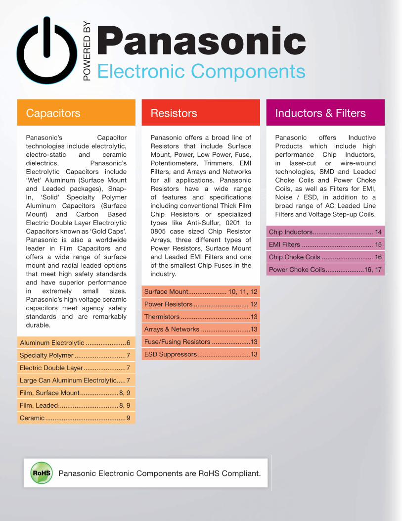
Panasonic offers a broad line of Resistors that include Surface Mount, Power, Low Power, Fuse, Potentiometers, Trimmers, EMI Filters, and Arrays and Networks for all applications. Panasonic Resistors have a wide range of features and specifi cations including conventional Thick Film Chip Resistors or specialized types like Anti-Sulfur, 0201 to 0805 case sized Chip Resistor Arrays, three different types of Power Resistors, Surface Mount and Leaded EMI Filters and one of the smallest Chip Fuses in the industry.
Surface Mount..................... 10, 11, 12
Power Resistors .............................. 12
Thermistors ......................................13
Arrays & Networks ...........................13
Fuse/Fusing Resistors .....................13
ESD Suppressors .............................13
Capacitors
Panasonic’s Capacitor technologies include electrolytic, electro-static and ceramic dielectrics. Panasonic’s Electrolytic Capacitors include ‘Wet’ Aluminum (Surface Mount and Leaded packages), Snap-In, ‘Solid’ Specialty Polymer Aluminum Capacitors (Surface Mount) and Carbon Based Electric Double Layer Electrolytic Capacitors known as ‘Gold Caps’. Panasonic is also a worldwide leader in Film Capacitors and offers a wide range of surface mount and radial leaded options that meet high safety standards and have superior performance in extremely small sizes. Panasonic’s high voltage ceramic capacitors meet agency safety standards and are remarkably durable.
Aluminum Electrolytic ......................6
Specialty Polymer ............................7
Electric Double Layer .......................7
Large Can Aluminum Electrolytic .....7
Film, Surface Mount .....................8, 9
Film, Leaded .................................8, 9
Ceramic ............................................9
Inductors & Filters
Panasonic offers Inductive Products which include high performance Chip Inductors, in laser-cut or wire-wound technologies, SMD and Leaded Choke Coils and Power Choke Coils, as well as Filters for EMI, Noise / ESD, in addition to a broad range of AC Leaded Line Filters and Voltage Step-up Coils.
Chip Inductors ................................. 14
EMI Filters ....................................... 15
Chip Choke Coils ............................ 16
Power Choke Coils .....................16, 17
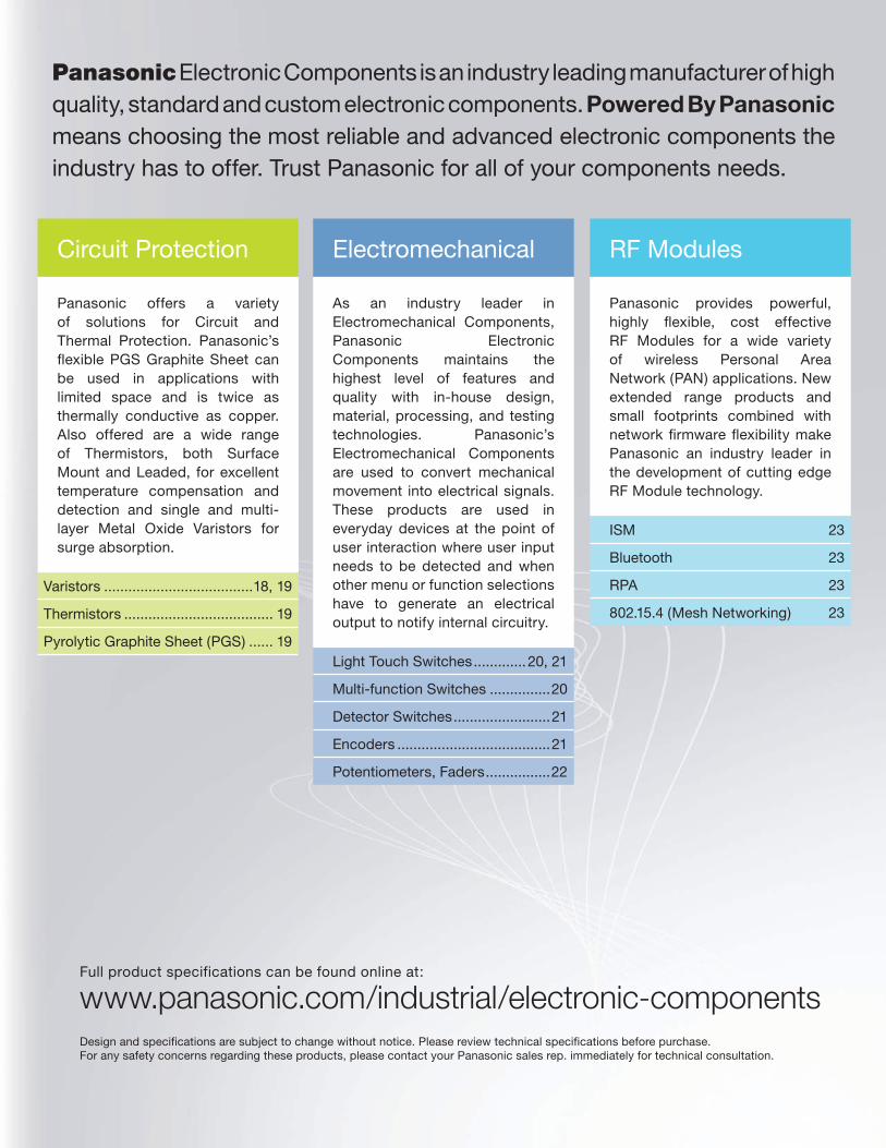
Panasonic Electronic Components is an industry leading manufacturer of high quality, standard and custom electronic components. Powered By Panasonic means choosing the most reliable and advanced electronic components the industry has to offer. Trust Panasonic for all of your components needs.
RF Modules
Panasonic provides powerful, highly fl exible, cost effective RF Modules for a wide variety of wireless Personal Area Network (PAN) applications. New extended range products and small footprints combined with network fi rmware fl exibility make Panasonic an industry leader in the development of cutting edge RF Module technology.
ISM 23
Bluetooth 23
RPA 23
802.15.4 (Mesh Networking) 23
Electromechanical
As an industry leader in Electromechanical Components, Panasonic Electronic Components maintains the highest level of features and quality with in-house design, material, processing, and testing technologies. Panasonic’s Electromechanical Components are used to convert mechanical movement into electrical signals. These products are used in everyday devices at the point of user interaction where user input needs to be detected and when other menu or function selections have to generate an electrical output to notify internal circuitry.
Light Touch Switches .............20, 21
Multi-function Switches ...............20
Detector Switches ........................21
Encoders ......................................21
Potentiometers, Faders ................22
Design and specifications are subject to change without notice. Please review technical specifications before purchase.For any safety concerns regarding these products, please contact your Panasonic sales rep. immediately for technical consultation.
www.panasonic.com/industrial/electronic-componentsFull product specifications can be found online at:
Circuit Protection
Panasonic offers a variety of solutions for Circuit and Thermal Protection. Panasonic’s fl exible PGS Graphite Sheet can be used in applications with limited space and is twice as thermally conductive as copper. Also offered are a wide range of Thermistors, both Surface Mount and Leaded, for excellent temperature compensation and detection and single and multi-layer Metal Oxide Varistors for surge absorption.
Varistors .....................................18, 19
Thermistors ..................................... 19
Pyrolytic Graphite Sheet (PGS) ...... 19
4
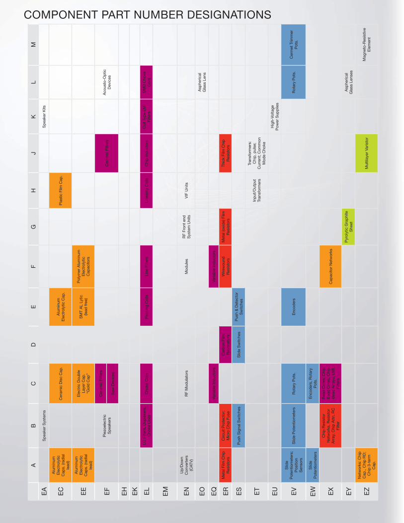
COMPONENT PART NUMBER DESIGNATIONS
AB
CD
EF
GH
JK
LM
EA
Sp
eake
r S
yste
ms
Sp
eake
r K
its
EC
Alu
min
um
Ele
ctro
lytic
C
aps.
(rad
ial
lead
)
Cer
amic
Dis
c C
ap.
Alu
min
um
Ele
ctro
lytic
Cap
.P
last
ic F
ilm C
ap.
EE
Alu
min
um
Ele
ctro
lytic
C
aps.
(rad
ial
lead
)
Ele
ctric
Dou
ble
La
yer
Cap
.“G
old
Cap
”
SM
T A
L Ly
tic
(lead
free
)
Pol
ymer
Alu
min
um
Ele
ctro
lytic
C
apac
itors
EF
Pie
zoel
ectr
ic
Sp
eake
rs
Cer
amic
Filt
ers
Cer
amic
Filt
ers
Aco
usto
-Op
tic
Dev
ices
Saw
Dev
ices
EH
EK EL
LC F
ilter
s, D
uple
xers
, C
hoke
Coi
lsC
hoke
Coi
lsP
eaki
ng C
oils
Line
Filt
ers
Line
arity
Coi
lsC
hip
Ind
ucto
rsC
oil T
ype
EM
I Fi
lters
SM
D C
hoke
C
oils
EM EN
Up
/Dow
n C
onve
rter
s (C
ATV
)R
F M
odul
ator
sM
odul
esR
F Fr
ont
end
S
yste
m U
nits
VIF
Uni
ts
EO
Asp
heric
al
Gla
ss L
ens
EQ
Varia
ble
Ind
ucto
rsVa
riab
le In
duc
tors
ER
Met
al F
ilm C
hip
R
esis
tors
Circ
uit
Pro
tect
or;
Mic
ro C
hip
Fus
eC
arb
on F
ilm
Res
onat
ors
Wire
wou
nd
Res
isto
rsM
etal
(oxi
de)
Film
R
esis
tors
Thic
k Fi
lm C
hip
R
esis
tors
ES
Pus
h S
igna
l Sw
itche
sS
lide
Sw
itche
sP
ush
& D
etec
tor
Sw
itche
s
ET
Inp
ut/O
utp
ut
Tran
sfor
mer
s
Tran
sfor
mer
s:
Chi
p, p
ulse
; C
urre
nt; C
omm
on
Mod
e C
hoke
EU
Hig
h-Vo
ltage
P
ower
Sup
plie
s
EV
Slid
e P
oten
tiom
eter
s;
Pos
ition
S
enso
rs
Slid
e P
oten
tiom
eter
sR
otar
y P
ots.
Enc
oder
sR
otar
y P
ots.
Cer
met
Trim
mer
P
ots.
EW
Slid
e P
oten
tiom
eter
sE
ncod
ers,
Rot
ary
Pot
s.
EX
Chi
p R
esis
tor
Net
wor
ks, R
esis
tor
Arr
ay, C
hip
Att
n, R
C
Filte
r
Bea
d C
ores
; Chi
p
Bea
d C
ores
, Chi
p
Bea
d A
rray
s, E
MI
Filte
rs
Cap
acito
r N
etw
orks
EY
Pyr
olyt
ic G
rap
hite
S
heet
Asp
heric
al
Gla
ss L
ense
s
EZ
Net
wor
ks: C
hip
C
ap.,
Chi
p R
D;
Chi
p 3
-ter
m
Cap
.
Mul
tilay
er V
aris
tor
Mag
neto
-Res
istiv
e E
lem
ent
5
Cap
acito
rsR
esis
tors
Ind
ucto
rs &
Filt
ers
Circ
uit
Pro
tect
ion
Ele
ctro
mec
hani
cal
RF
Mod
ules
The
se E
lect
roni
c C
om
po
nent
s ar
e no
t in
clud
ed in
thi
s ca
talo
g b
ut c
an
be
foun
d o
n th
e P
anas
oni
c E
lect
roni
c C
om
po
nent
s w
eb s
ite.
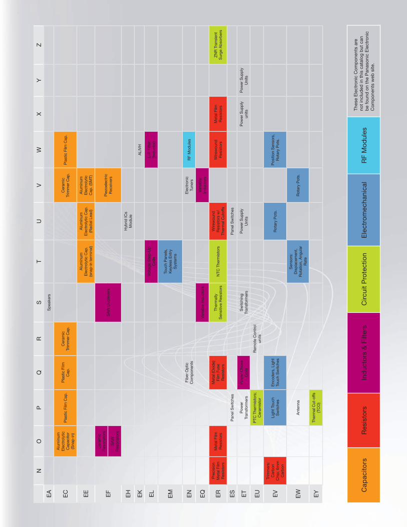
NO
PQ
RS
TU
VW
XY
Z
EA
Sp
eake
rs
EC
Alu
min
um
Ele
ctro
lytic
C
apac
itor
(Sna
p-i
n)
Pla
stic
Film
Cap
.P
last
ic F
ilm
Cap
.C
eram
ic
Trim
mer
Cap
.C
eram
ic
Trim
mer
Cap
.P
last
ic F
ilm C
ap.
EE
Alu
min
um
Ele
ctro
lytic
Cap
. (s
nap
-in
term
inal
)
Alu
min
um
Ele
ctro
lytic
Cap
. (R
adia
l Lea
d)
Alu
min
um
Ele
ctro
lytic
C
ap. (
SM
T)
EF
Cer
amic
R
eson
ator
sS
AW
Dup
lexe
rsP
iezo
elec
tric
R
ecei
vers
SA
W
Res
onat
ors
EH
Hyb
rid IC
s M
odul
e
EK
ALI
VH
EL
Volta
ge S
tep
-Up
C
oils
L-R
Filt
er
(Ind
ucto
r)
EM
Touc
h P
anel
s,
Key
less
Ent
ry
Sys
tem
s
EN
Fib
er O
ptic
C
omp
onen
tsE
lect
roni
c Tu
ners
RF
Mod
ules
EQ
Varia
ble
Ind
ucto
rsVa
riab
le
Ind
ucto
rs
ER
Pre
cisi
on
Met
al F
ilm
Res
isto
rs
Met
al F
ilm
Res
isto
rs
Met
al (O
xid
e)
Film
Fus
e R
esis
tors
Ther
mal
ly
Sen
sitiv
e R
esis
tors
NTC
The
rmis
tors
Wire
wou
nd
Res
isto
rs w
/ Th
erm
al C
utof
fs
Wire
wou
nd
Res
isto
rsM
etal
Film
R
esis
tors
ZN
R T
rans
ient
S
urge
Ab
sorb
ers
ES
Pan
el S
witc
hes
Pan
el S
witc
hes
ET
Pow
er
Tran
sfor
mer
sP
ower
Cho
ke
Coi
lsS
witc
hing
Tr
ansf
orm
ers
Pow
er S
upp
ly
Uni
tsP
ower
Sup
ply
un
itsP
ower
Sup
ply
U
nits
EU
PTC
The
rmis
tors
; C
eram
isto
rR
emot
e C
ontr
ol
units
EV
Trim
mer
s:
Car
bon
C
hip
; 6m
m
Car
bon
Ligh
t To
uch
Sw
itche
sE
ncod
ers,
Lig
ht
Touc
h S
witc
hes
Rot
ary
Pot
s.P
ositi
on S
enso
rs,
Rot
ary
Pot
s.
EW
Ant
enna
Sen
sors
: D
isp
lace
men
t,
Rot
atio
n, A
ngul
ar
Rat
e
Rot
ary
Pot
s.
EY
Ther
mal
Cut
-offs
(T
CO
)

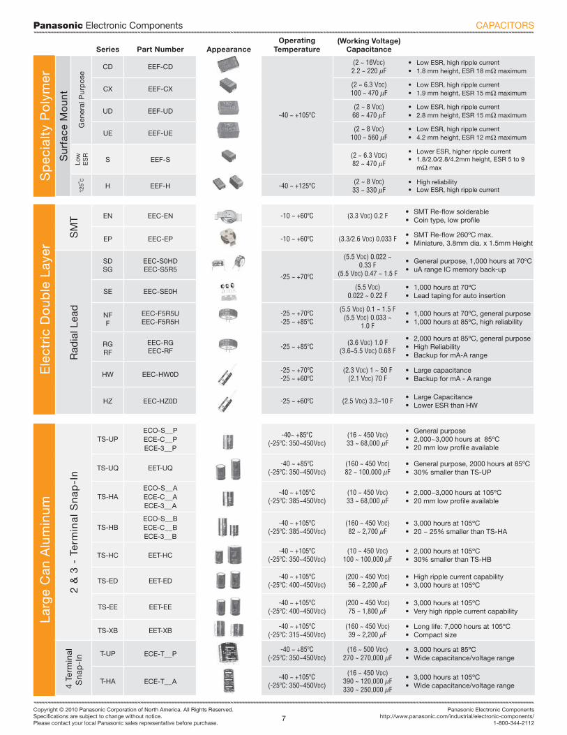
Panasonic Electronic Components
6Copyright © 2010 Panasonic Corporation of North America. All Rights Reserved.Specifi cations are subject to change without notice.Please contact your local Panasonic sales representative before purchase.
http://www.panasonic.com/industrial/electronic-components/[email protected]
1-800-344-2112
*NOTE: Surface Mount Type RoHS Compliant Part Number Prefi x: EEE (Diameter: 3~10mm) EEV (Diameter: 12.5~18mm)
NOTE: For higher temperature refl ow, use EEE (A_) suffi x: 260ºC Max. Refl ow: AP & AR (4~10mm dia.) 245ºC Max. Refl ow: AQ & AM (12.5~18mm dia.)
Series Series AppearanceOperating
Temperature(Working Voltage)
Capacitance Features
Alu
min
um E
lect
roly
tic
Sur
face
Mo
unt
Typ
e*
Gen
eral
P
urpo
se
VS EEE-_A/S -40 ~ +85ºC(4 ~ 100 VDC)0.1 ~ 1,500 uF
• General purpose, 2,000 hours at 85ºC• Very compact size
Long
Life
HA EEE-HA
-40 ~ +105ºC
(6.3 ~ 100 VDC)0.1 ~ 1,500 uF
• Long life, 1000~2,000 hours at 105ºC• Very compact size
HB EEE-HB(4 ~ 50 VDC)0.1 ~ 470 uF
• Long life, 2,000 hours at 105ºC• 5.8 mm height (< b 6)
HC EEE-HC(6.3 ~ 50 VDC)33 ~ 1,000 uF
• Long life, 3,000~5,000 hours at 105ºC• 5.8 mm height (< b 6)
HDEEE-HD
(6.3 ~ 50 VDC)0.1 ~ 1000 uF
• Very long life, 5,000 hours at 105ºC• Industrial grade
TG EEE-TG
-40 ~ +125ºC
(10 ~ 100 VDC)10 ~ 4,700 uF
• High temperature, 2,000 hours at 125ºC• Low ESR at low temperature
TK EEE-TK(10 ~ 35 VDC)47 ~ 4700 uF
• High temperature, 3,000 hours at 125ºC• Low ESR at low temperature
TP EEE-TP(10 ~ 35 VDC)47 ~ 470 uF
• Low ESR at Low Temperatures• 2,000~3,000 hours at 125ºC
Low
ES
R/L
ong
Life FP EEE-FP
-55 ~ +105ºC
(6.3 ~ 35 VDC)100 ~ 1,800 uF
• Very Low ESR, tantalum replacement• High Temperature Refl ow (260ºC)
FK EEE-FK(6.3 ~ 100 VDC)3.3 ~ 6,800 uF
• Long life, 2,000~5,000 hours at 105ºC• Low ESR, Tantalum replacement• Compact, wide size range: 4~18 mm (Dia)
FC EEE-FC -40 ~ +105ºC(6.3 ~ 50 VDC)1 ~ 1,500 uF
• 1,000 hours at 105ºC• Low impedance
Bi-
Po
lar VS-BP EEE-V__A___N -40 ~ +85ºC
(6.3 ~ 50 VDC)0.22 ~ 47 uF
• General Purpose• 5.4 mm height (< b 6)
HB-BP EEE-HP -40 ~ +105ºC• Industrial Grade• 5.8 mm height
Rad
ial L
ead
Gen
eral
Pur
po
se
85d
C
M ECA-__M-40 ~ +85ºC
(-25ºC: 160~450VDC)(6.3 ~ 450 VDC)0.1 ~ 22,000 uF
• General purpose, 2000 hours at 85ºC• Compact size
10
5dC
NHG ECA-__HG-55 ~ +105ºC
(-25ºC: 160~450VDC)(6.3 ~ 450 VDC)0.1 ~ 22,000 uF
• Long life, 1,000~2,000 hours at 105ºC• Compact size
Min
iatu
re KA ECE-A__KA-40 ~ +85ºC
(4 ~ 50 VDC)0.1 ~ 470 uF
• General purpose, 1,000 hours at 85ºC• 7 mm height
KS ECE-A__KK/KS(4 ~ 50 VDC)0.1 ~ 330 uF
• General purpose, 1000 hours at 85ºC• 5 mm height
Bi-
Pol
ar
BP-SU ECE-A__N___U/X -40 ~ +85ºC(6.3 ~ 50 VDC)0.47 ~ 6,800 uF
• 2,000 hours at 85ºC• Bi-Polar general purpose
Long
Life
Hig
h V
olt
ag
e EB EEU-EB-40 ~ +105ºC
(-25ºC: 160~450VDC)(10 ~ 450 VDC)0.47 ~ 3,300 uF
• 5,000~10,000 hours at 105ºC• Very long life
ED EEU-ED -25 ~ +105ºC(160 ~ 450 VDC)
10 ~ 330 uF• Very long life 8,000~10,000 hours at 105ºC• High Ripple Current
EE EEU-EE -25 ~ +105ºC(160 ~ 450 VDC)
10 ~ 330 uF• Very long life 8,000~10,000 hours at 105ºC• High Ripple Current at high frequency
Low
Imp
edan
ce FC EEA/U-FC -55 ~ +105ºC(6.3 ~ 100 VDC)1.0 ~ 15,000 uF
• 1,000~5,000 hours at 105ºC• Low impedance, miniature
FM EEU-FM -40 ~ +105ºC(6.3 ~ 50 VDC)22 ~ 6,800 uF
• Long life, 2,000~7,000 hours at 105ºC• Low ESR, approximately half of FC
125º
C
TA EEU-TA -40 ~ +125ºC(10 ~ 63 VDC)1 ~ 4,700 uF
• 2,000 hours at 125ºC• Automotive applications
_
_
_
CAPACITORS
Panasonic Electronic Components
7Copyright © 2010 Panasonic Corporation of North America. All Rights Reserved.Specifi cations are subject to change without notice.Please contact your local Panasonic sales representative before purchase.
Panasonic Electronic Componentshttp://www.panasonic.com/industrial/electronic-components/
1-800-344-2112
Larg
e C
an A
lum
inum
2 &
3 -
Te
rmin
al
Sn
ap
-In
TS-UPECO-S__PECE-C__PECE-3__P
-40~ +85ºC(-25ºC: 350~450VDC)
(16 ~ 450 VDC)33 ~ 68,000 uF
• General purpose• 2,000~3,000 hours at 85ºC• 20 mm low profi le available
TS-UQ EET-UQ-40 ~ +85ºC
(-25ºC: 350~450VDC)(160 ~ 450 VDC)82 ~ 100,000 uF
• General purpose, 2000 hours at 85ºC• 30% smaller than TS-UP
TS-HAECO-S__AECE-C__AECE-3__A
-40 ~ +105ºC(-25ºC: 385~450VDC)
(10 ~ 450 VDC)33 ~ 68,000 uF
• 2,000~3,000 hours at 105ºC• 20 mm low profi le available
TS-HBECO-S__BECE-C__BECE-3__B
-40 ~ +105ºC(-25ºC: 385~450VDC)
(160 ~ 450 VDC)82 ~ 2,700 uF
• 3,000 hours at 105ºC• 20 ~ 25% smaller than TS-HA
TS-HC EET-HC-40 ~ +105ºC
(-25ºC: 350~450VDC)(10 ~ 450 VDC)
100 ~ 100,000 uF• 2,000 hours at 105ºC• 30% smaller than TS-HB
TS-ED EET-ED-40 ~ +105ºC
(-25ºC: 400~450VDC)(200 ~ 450 VDC)56 ~ 2,200 uF
• High ripple current capability• 3,000 hours at 105ºC
TS-EE EET-EE-40 ~ +105ºC
(-25ºC: 400~450VDC)(200 ~ 450 VDC)75 ~ 1,800 uF
• 3,000 hours at 105ºC• Very high ripple current capability
TS-XB EET-XB-40 ~ +105ºC
(-25ºC: 315~450VDC)(160 ~ 450 VDC)39 ~ 2,200 uF
• Long life: 7,000 hours at 105ºC• Compact size
4 T
erm
inal
Sna
p-I
n
T-UP ECE-T__P-40 ~ +85ºC
(-25ºC: 350~450VDC)(16 ~ 500 VDC)
270 ~ 270,000 uF• 3,000 hours at 85ºC• Wide capacitance/voltage range
T-HA ECE-T__A-40 ~ +105ºC
(-25ºC: 350~450VDC)
(16 ~ 450 VDC)390 ~ 120,000 uF330 ~ 250,000 uF
• 3,000 hours at 105ºC• Wide capacitance/voltage range
Series Part Number AppearanceOperating
Temperature(Working Voltage)
CapacitanceS
pec
ialt
y P
oly
mer
Sur
face
Mo
unt
Gen
eral
Pur
po
se
CD EEF-CD
-40 ~ +105ºC
(2 ~ 16VDC)2.2 ~ 220 uF
• Low ESR, high ripple current• 1.8 mm height, ESR 18 mo maximum
CX EEF-CX(2 ~ 6.3 VDC)100 ~ 470 uF
• Low ESR, high ripple current• 1.9 mm height, ESR 15 mo maximum
UD EEF-UD(2 ~ 8 VDC)68 ~ 470 uF
• Low ESR, high ripple current• 2.8 mm height, ESR 15 mo maximum
UE EEF-UE(2 ~ 8 VDC)
100 ~ 560 uF• Low ESR, high ripple current• 4.2 mm height, ESR 12 mo maximum
Low
ES
R
S EEF-S(2 ~ 6.3 VDC)82 ~ 470 uF
• Lower ESR, higher ripple current• 1.8/2.0/2.8/4.2mm height, ESR 5 to 9
mo max
125º
C
H EEF-H -40 ~ +125ºC (2 ~ 8 VDC)33 ~ 330 uF
• High reliability• Low ESR, high ripple current
Ele
ctri
c D
oub
le L
ayer
SM
T EN EEC-EN -10 ~ +60ºC (3.3 VDC) 0.2 F • SMT Re-fl ow solderable• Coin type, low profi le
EP EEC-EP -10 ~ +60ºC (3.3/2.6 VDC) 0.033 F • SMT Re-fl ow 260ºC max.• Miniature, 3.8mm dia. x 1.5mm Height
Rad
ial L
ead
SDSG
EEC-S0HDEEC-S5R5
-25 ~ +70ºC
(5.5 VDC) 0.022 ~ 0.33 F
(5.5 VDC) 0.47 ~ 1.5 F
• General purpose, 1,000 hours at 70ºC• uA range IC memory back-up
SE EEC-SE0H(5.5 VDC)
0.022 ~ 0.22 F• 1,000 hours at 70ºC• Lead taping for auto insertion
NFF
EEC-F5R5UEEC-F5R5H
-25 ~ +70ºC-25 ~ +85ºC
(5.5 VDC) 0.1 ~ 1.5 F(5.5 VDC) 0.033 ~
1.0 F
• 1,000 hours at 70ºC, general purpose• 1,000 hours at 85ºC, high reliability
RGRF
EEC-RGEEC-RF
-25 ~ +85ºC (3.6 VDC) 1.0 F(3.6~5.5 VDC) 0.68 F
• 2,000 hours at 85ºC, general purpose• High Reliability• Backup for mA-A range
HW EEC-HW0D-25 ~ +70ºC-25 ~ +60ºC
(2.3 VDC) 1 ~ 50 F(2.1 VDC) 70 F
• Large capacitance• Backup for mA - A range
HZ EEC-HZ0D -25 ~ +60ºC (2.5 VDC) 3.3~10 F • Large Capacitance• Lower ESR than HW
CAPACITORS
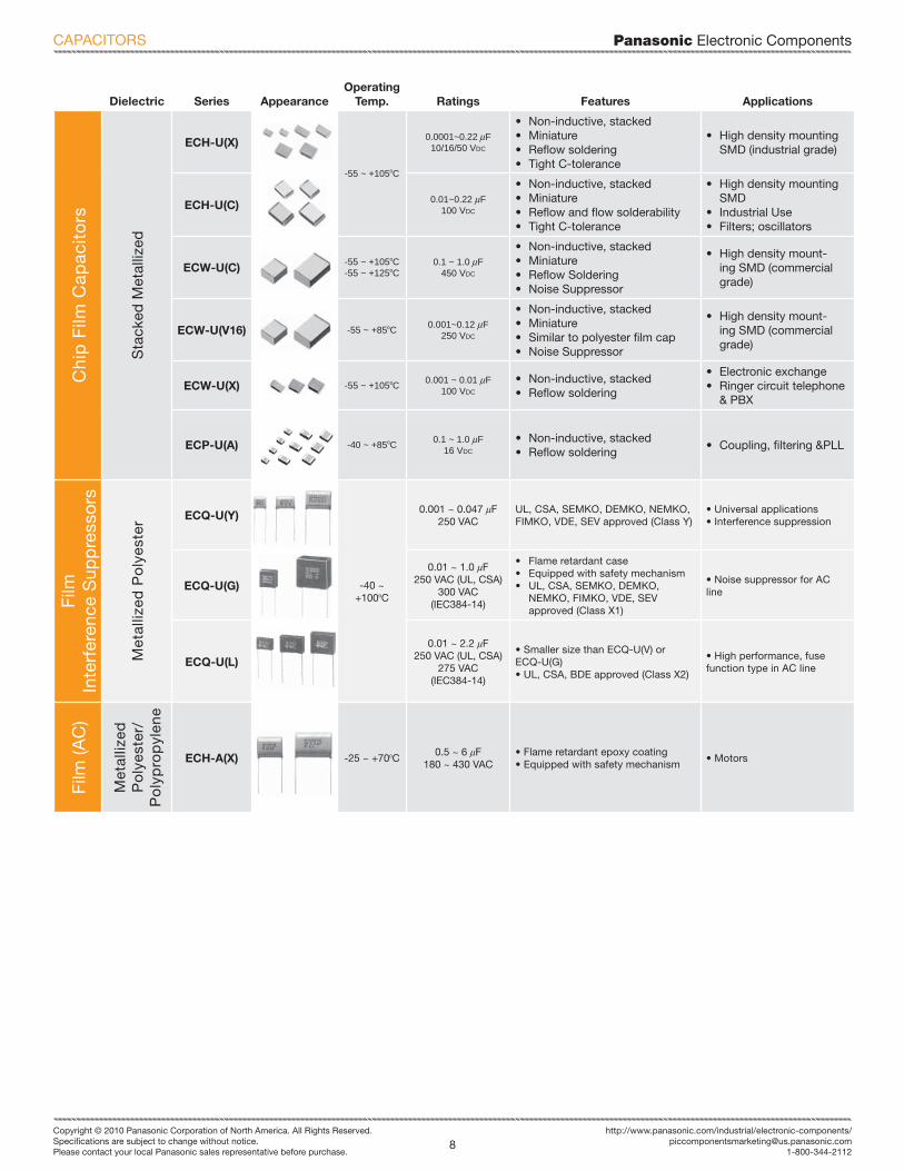
Panasonic Electronic Components
8Copyright © 2010 Panasonic Corporation of North America. All Rights Reserved.Specifi cations are subject to change without notice.Please contact your local Panasonic sales representative before purchase.
http://www.panasonic.com/industrial/electronic-components/[email protected]
1-800-344-2112
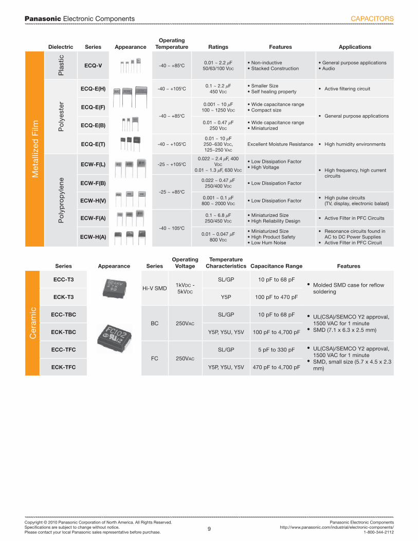
Dielectric Series AppearanceOperating
Temp. Ratings Features Applications
Chi
p F
ilm C
apac
ito
rs
Sta
cked
Met
alliz
edECH-U(X)
-55 ~ +105ºC
0.0001~0.22 uF10/16/50 VDC
• Non-inductive, stacked• Miniature• Refl ow soldering• Tight C-tolerance
• High density mounting SMD (industrial grade)
ECH-U(C) 0.01~0.22 uF100 VDC
• Non-inductive, stacked• Miniature• Refl ow and fl ow solderability• Tight C-tolerance
• High density mounting SMD
• Industrial Use• Filters; oscillators
ECW-U(C) -55 ~ +105ºC-55 ~ +125ºC
0.1 ~ 1.0 uF450 VDC
• Non-inductive, stacked• Miniature• Refl ow Soldering• Noise Suppressor
• High density mount-ing SMD (commercial grade)
ECW-U(V16) -55 ~ +85ºC 0.001~0.12 uF250 VDC
• Non-inductive, stacked• Miniature• Similar to polyester fi lm cap• Noise Suppressor
• High density mount-ing SMD (commercial grade)
ECW-U(X) -55 ~ +105ºC 0.001 ~ 0.01 uF100 VDC
• Non-inductive, stacked• Refl ow soldering
• Electronic exchange• Ringer circuit telephone
& PBX
ECP-U(A) -40 ~ +85ºC 0.1 ~ 1.0 uF16 VDC
• Non-inductive, stacked• Refl ow soldering
• Coupling, fi ltering &PLL
Film
Inte
rfer
ence
Sup
pre
sso
rs
Met
alliz
ed P
oly
este
r ECQ-U(Y)
-40 ~ +100ºC
0.001 ~ 0.047 uF250 VAC
UL, CSA, SEMKO, DEMKO, NEMKO, FIMKO, VDE, SEV approved (Class Y)
• Universal applications• Interference suppression
ECQ-U(G)
0.01 ~ 1.0 uF250 VAC (UL, CSA)
300 VAC(IEC384-14)
• Flame retardant case• Equipped with safety mechanism• UL, CSA, SEMKO, DEMKO,
NEMKO, FIMKO, VDE, SEV approved (Class X1)
• Noise suppressor for AC line
ECQ-U(L)
0.01 ~ 2.2 uF250 VAC (UL, CSA)
275 VAC(IEC384-14)
• Smaller size than ECQ-U(V) or ECQ-U(G)• UL, CSA, BDE approved (Class X2)
• High performance, fuse function type in AC line
Film
(AC
)
Met
alliz
edP
oly
este
r/P
oly
pro
pyl
ene
ECH-A(X) -25 ~ +70ºC0.5 ~ 6 uF
180 ~ 430 VAC• Flame retardant epoxy coating• Equipped with safety mechanism
• Motors
CAPACITORS
Panasonic Electronic Components
9Copyright © 2010 Panasonic Corporation of North America. All Rights Reserved.Specifi cations are subject to change without notice.Please contact your local Panasonic sales representative before purchase.
Panasonic Electronic Componentshttp://www.panasonic.com/industrial/electronic-components/
1-800-344-2112
Dielectric Series AppearanceOperating
Temperature Ratings Features Applications
Met
alliz
ed F
ilm
Pla
stic
ECQ-V -40 ~ +85ºC0.01 ~ 2.2 uF
50/63/100 VDC
• Non-inductive• Stacked Construction
• General purpose applications• Audio
Po
lyes
ter
ECQ-E(H) -40 ~ +105ºC0.1 ~ 2.2 uF
450 VDC
• Smaller Size• Self healing property
• Active fi ltering circuit
ECQ-E(F)
-40 ~ +85ºC
0.001 ~ 10 uF100 ~ 1250 VDC
• Wide capacitance range• Compact size
• General purpose applications
ECQ-E(B) 0.01 ~ 0.47 uF250 VDC
• Wide capacitance range• Miniaturized
ECQ-E(T) -40 ~ +105ºC0.01 ~ 10 uF250~630 VDC,125~250 VAC
Excellent Moisture Resistance • High humidity environments
Po
lyp
rop
ylen
e
ECW-F(L) -25 ~ +105ºC0.022 ~ 2.4 uF, 400
VDC
0.01 ~ 1.3 uF, 630 VDC
• Low Dissipation Factor• High Voltage
• High frequency, high current circuits
ECW-F(B)
-25 ~ +85ºC
0.022 ~ 0.47 uF250/400 VDC
• Low Dissipation Factor
ECW-H(V) 0.001 ~ 0.1 uF800 ~ 2000 VDC
• Low Dissipation Factor• High pulse circuits
(TV, display, electronic balast)
ECW-F(A)
-40 ~ 105ºC
0.1 ~ 6.8 uF250/450 VDC
• Miniaturized Size• High Reliability Design
• Active Filter in PFC Circuits
ECW-H(A) 0.01 ~ 0.047 uF800 VDC
• Miniaturized Size• High Product Safety• Low Hum Noise
• Resonance circuits found in AC to DC Power Supplies
• Active Filter in PFC Circuit
Series Appearance SeriesOperating
VoltageTemperature
Characteristics Capacitance Range Features
Cer
amic
ECC-T3
Hi-V SMD1kVDC - 5kVDC
SL/GP 10 pF to 68 pF• Molded SMD case for reflow
solderingECK-T3 Y5P 100 pF to 470 pF
ECC-TBC
BC 250VAC
SL/GP 10 pF to 68 pF • UL(CSA)/SEMCO Y2 approval, 1500 VAC for 1 minute
• SMD (7.1 x 6.3 x 2.5 mm)ECK-TBC Y5P, Y5U, Y5V 100 pF to 4,700 pF
ECC-TFC
FC 250VAC
SL/GP 5 pF to 330 pF • UL(CSA)/SEMCO Y2 approval, 1500 VAC for 1 minute
• SMD, small size (5.7 x 4.5 x 2.3 mm)ECK-TFC Y5P, Y5U, Y5V 470 pF to 4,700 pF
CAPACITORS
Panasonic Electronic Components
10Copyright © 2010 Panasonic Corporation of North America. All Rights Reserved.Specifi cations are subject to change without notice.Please contact your local Panasonic sales representative before purchase.
http://www.panasonic.com/industrial/electronic-components/[email protected]
1-800-344-2112
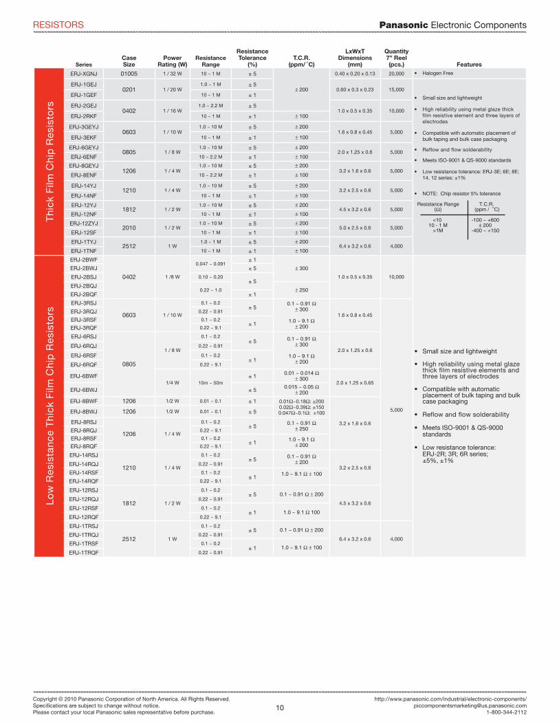
SeriesCaseSize
PowerRating (W)
ResistanceRange
ResistanceTolerance
(%)T.C.R.
(ppm/dC)
LxWxTDimensions
(mm)
Quantity7” Reel (pcs.) Features
Thi
ck F
ilm C
hip
Res
isto
rs
ERJ-XGNJ 01005 1 / 32 W 10 ~ 1 M ± 5
* 200
0.40 x 0.20 x 0.13 20,000
• Small size and lightweight
• High reliability using metal glaze thick film resistive element and three layers of electrodes
• Compatible with automatic placement of bulk taping and bulk case packaging
• Reflow and flow solderability
• Meets ISO-9001 & QS-9000 standards
• Low resistance tolerance: ERJ-3E; 6E; 8E; 14, 12 series: ±1%
• NOTE: Chip resistor 5% tolerance
Resistance Range T.C.R. (o) (ppm /dC)
<10 -100 ~ +600 10 - 1 M * 200 >1M -400 ~ +150
ERJ-1GEJ0201 1 / 20 W
1.0 ~ 1 M ± 50.60 x 0.3 x 0.23 15,000
ERJ-1GEF 10 ~ 1 M ± 1
ERJ-2GEJ0402 1 / 16 W
1.0 ~ 2.2 M ± 51.0 x 0.5 x 0.35 10,000
ERJ-2RKF 10 ~ 1 M ± 1 * 100
ERJ-3GEYJ0603 1 / 10 W
1.0 ~ 10 M ± 5 * 2001.6 x 0.8 x 0.45 5,000
ERJ-3EKF 10 ~ 1 M ± 1 * 100
ERJ-6GEYJ0805 1 / 8 W
1.0 ~ 10 M ± 5 * 2002.0 x 1.25 x 0.6 5,000
ERJ-6ENF 10 ~ 2.2 M ± 1 * 100
ERJ-8GEYJ1206 1 / 4 W
1.0 ~ 10 M ± 5 * 2003.2 x 1.6 x 0.6 5,000
ERJ-8ENF 10 ~ 2.2 M ± 1 * 100
ERJ-14YJ1210 1 / 4 W
1.0 ~ 10 M ± 5 * 2003.2 x 2.5 x 0.6 5,000
ERJ-14NF 10 ~ 1 M ± 1 * 100
ERJ-12YJ1812 1 / 2 W
1.0 ~ 10 M ± 5 * 2004.5 x 3.2 x 0.6 5,000
ERJ-12NF 10 ~ 1 M ± 1 * 100
ERJ-12ZYJ2010 1 / 2 W
1.0 ~ 10 M ± 5 * 2005.0 x 2.5 x 0.6 5,000
ERJ-12SF 10 ~ 1 M ± 1 * 100
ERJ-1TYJ2512 1 W
1.0 ~ 1 M ± 5 * 2006.4 x 3.2 x 0.6 4,000
ERJ-1TNF 10 ~ 1 M ± 1 * 100
Low
Res
ista
nce
Thi
ck F
ilm C
hip
Res
isto
rs
ERJ-2BWF
0402 1 /8 W
0.047 ~ 0.091± 1
* 300
1.0 x 0.5 x 0.35 10,000
• Small size and lightweight
• High reliability using metal glaze thick film resistive elements and three layers of electrodes
• Compatible with automatic placement of bulk taping and bulk case packaging
• Reflow and flow solderability
• Meets ISO-9001 & QS-9000 standards
• Low resistance tolerance: ERJ-2R; 3R; 6R series;±5%, ±1%
ERJ-2BWJ ± 5
ERJ-2BSJ 0.10 ~ 0.20± 5
ERJ-2BQJ0.22 ~ 1.0 * 250
ERJ-2BQF ± 1
ERJ-3RSJ
0603 1 / 10 W
0.1 ~ 0.2± 5
0.1 ~ 0.91 o* 300
1.0 ~ 9.1 o* 200
1.6 x 0.8 x 0.45
5,000
ERJ-3RQJ 0.22 ~ 0.91
ERJ-3RSF 0.1 ~ 0.2± 1
ERJ-3RQF 0.22 ~ 9.1
ERJ-6RSJ
0805
1 / 8 W
0.1 ~ 0.2± 5 0.1 ~ 0.91 o
* 300
1.0 ~ 9.1 o* 200
2.0 x 1.25 x 0.6ERJ-6RQJ 0.22 ~ 0.91
ERJ-6RSF 0.1 ~ 0.2± 1
ERJ-6RQF 0.22 ~ 9.1
ERJ-6BWF1/4 W 10m ~ 50m
± 1 0.01 ~ 0.014 o* 300
2.0 x 1.25 x 0.65ERJ-6BWJ ± 5 0.015 ~ 0.05 o
* 200
ERJ-8BWF 1206 1/2 W 0.01 ~ 0.1 ± 1 0.01o~0.18o: ±2000.02o~0.39o: ±1500.047o~0.1o: ±100
3.2 x 1.6 x 0.6
ERJ-8BWJ 1206 1/2 W 0.01 ~ 0.1 ± 5
ERJ-8RSJ
1206 1 / 4 W
0.1 ~ 0.2± 5 0.1 ~ 0.91 o
* 250ERJ-8RQJ 0.22 ~ 9.1
ERJ-8RSF 0.1 ~ 0.2± 1 1.0 ~ 9.1 o
* 200ERJ-8RQF 0.22 ~ 9.1
ERJ-14RSJ
1210 1 / 4 W
0.1 ~ 0.2± 5 0.1 ~ 0.91 o
* 2003.2 x 2.5 x 0.6
ERJ-14RQJ 0.22 ~ 0.91
ERJ-14RSF 0.1 ~ 0.2± 1 1.0 ~ 9.1 o * 100
ERJ-14RQF 0.22 ~ 9.1
ERJ-12RSJ
1812 1 / 2 W
0.1 ~ 0.2± 5 0.1 ~ 0.91 o * 200
4.5 x 3.2 x 0.6ERJ-12RQJ 0.22 ~ 0.91
ERJ-12RSF 0.1 ~ 0.2± 1 1.0 ~ 9.1 o 100
ERJ-12RQF 0.22 ~ 9.1
ERJ-1TRSJ
2512 1 W
0.1 ~ 0.2± 5 0.1 ~ 0.91 o * 200
6.4 x 3.2 x 0.6 4,000ERJ-1TRQJ 0.22 ~ 0.91
ERJ-1TRSF 0.1 ~ 0.2± 1 1.0 ~ 9.1 o * 100
ERJ-1TRQF 0.22 ~ 0.91
• Halogen Free
RESISTORS
Panasonic Electronic Components
11Copyright © 2010 Panasonic Corporation of North America. All Rights Reserved.Specifi cations are subject to change without notice.Please contact your local Panasonic sales representative before purchase.
Panasonic Electronic Componentshttp://www.panasonic.com/industrial/electronic-components/
1-800-344-2112
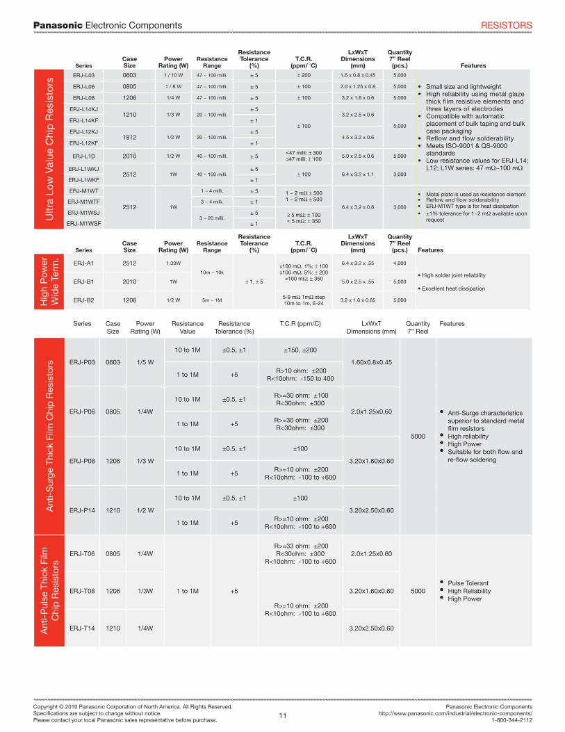
Series Case Size
Power Rating (W)
Resistance Value
Resistance Tolerance (%)
T.C.R (ppm/C) LxWxT Dimensions (mm)
Quantity 7” Reel
Features
Ant
i-S
urge
Thi
ck F
ilm C
hip
Res
isto
rs ERJ-P03 0603 1/5 W
10 to 1M ±0.5, ±1 ±150, ±200
1.60x0.8x0.45
5000
• Anti-Surge characteristics superior to standard metal film resistors
• High reliability• High Power• Suitable for both flow and
re-flow soldering
1 to 1M +5 R>10 ohm: ±200
R<10ohm: -150 to 400
ERJ-P06 0805 1/4W
10 to 1M ±0.5, ±1 R>=30 ohm: ±100
R<30ohm: ±3002.0x1.25x0.60
1 to 1M +5 R>=30 ohm: ±200
R<30ohm: ±300
ERJ-P08 1206 1/3 W
10 to 1M ±0.5, ±1 ±100
3.20x1.60x0.60
1 to 1M +5 R>=10 ohm: ±200
R<10ohm: -100 to +600
ERJ-P14 1210 1/2 W
10 to 1M ±0.5, ±1 ±100
3.20x2.50x0.60
1 to 1M +5 R>=10 ohm: ±200
R<10ohm: -100 to +600
Ant
i-P
ulse
Thi
ck F
ilm
Chi
p R
esis
tors
ERJ-T06 0805 1/4W
1 to 1M +5
R>=33 ohm: ±200 R<30ohm: ±300
R<10ohm: -100 to +6002.0x1.25x0.60
5000• Pulse Tolerant• High Reliability• High Power
ERJ-T08 1206 1/3W
R>=10 ohm: ±200 R<10ohm: -100 to +600
3.20x1.60x0.60
ERJ-T14 1210 1/4W 3.20x2.50x0.60
SeriesCaseSize
PowerRating (W)
ResistanceRange
ResistanceTolerance
(%)T.C.R.
(ppm/dC)
LxWxTDimensions
(mm)
Quantity7” Reel (pcs.) Features
Ultr
a Lo
w V
alue
Chi
p R
esis
tors
ERJ-L03 0603 1 / 10 W 47 ~ 100 milli. ± 5 * 200 1.6 x 0.8 x 0.45 5,000
• Small size and lightweight• High reliability using metal glaze
thick film resistive elements and three layers of electrodes
• Compatible with automatic placement of bulk taping and bulk case packaging
• Reflow and flow solderability• Meets ISO-9001 & QS-9000
standards• Low resistance values for ERJ-L14;
L12; L1W series: 47 mo~100 mo
ERJ-L06 0805 1 / 8 W 47 ~ 100 milli. ± 5 * 100 2.0 x 1.25 x 0.6 5,000
ERJ-L08 1206 1/4 W 47 ~ 100 milli. ± 5 * 100 3.2 x 1.6 x 0.6 5,000
ERJ-L14KJ1210 1/3 W 20 ~ 100 milli.
± 5
* 100
3.2 x 2.5 x 0.6
5,000ERJ-L14KF ± 1
ERJ-L12KJ1812 1/2 W 20 ~ 100 milli.
± 54.5 x 3.2 x 0.6
ERJ-L12KF ± 1
ERJ-L1D 2010 1/2 W 40 ~ 100 milli. ± 5,47 milli: * 300<47 milli: * 100
5.0 x 2.5 x 0.6 5,000
ERJ-L1WKJ2512 1W 40 ~ 100 milli.
± 5* 100 6.4 x 3.2 x 1.1 3,000
ERJ-L1WKF ± 1
ERJ-M1WT
2512 1W
1 ~ 4 milli. ± 5 1 ~ 2 mo * 5001 ~ 2 mo * 500
6.4 x 3.2 x 0.8 3,000
• Metal plate is used as resistance element• Reflow and flow solderability• ERJ-M1WT type is for heat dissipation• ±1% tolerance for 1~2 mo available upon
request
ERJ-M1WTF 3 ~ 4 milli. ± 1
ERJ-M1WSJ3 ~ 20 milli.
± 5 > 5 mo: * 100, 5 mo: * 350ERJ-M1WSF ± 1
SeriesCaseSize
PowerRating (W)
ResistanceRange
ResistanceTolerance
(%)T.C.R.
(ppm/dC)
LxWxTDimensions
(mm)
Quantity7” Reel (pcs.) Features
Hig
h P
ow
erW
ide
Term
.
ERJ-A1 2512 1.33W
10m ~ 10k
* 1, * 5
>100 mo, 1%: * 100>100 mo, 5%: * 200
<100 mo: * 350
6.4 x 3.2 x .55 4,000
• High solder joint reliability
• Excellent heat dissipationERJ-B1 2010 1W 5.0 x 2.5 x .55 5,000
ERJ-B2 1206 1/2 W 5m ~ 1M5-9 mo 1mo step10m to 1m, E-24
3.2 x 1.6 x 0.65 5,000
RESISTORS
Panasonic Electronic Components
12Copyright © 2010 Panasonic Corporation of North America. All Rights Reserved.Specifi cations are subject to change without notice.Please contact your local Panasonic sales representative before purchase.
http://www.panasonic.com/industrial/electronic-components/[email protected]
1-800-344-2112
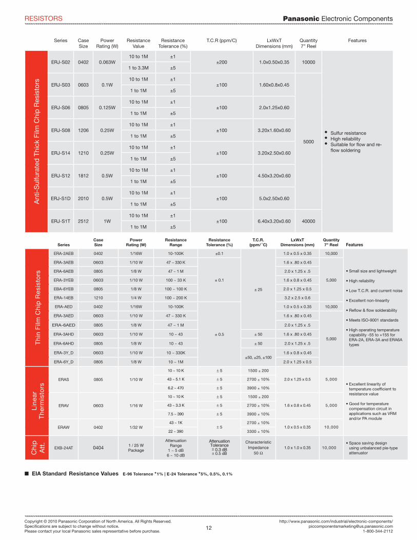
[ EIA Standard Resistance Values E-96 Tolerance *1% | E-24 Tolerance *5%, 0.5%, 0.1%
SeriesCaseSize
PowerRating (W)
ResistanceRange
ResistanceTolerance (%)
T.C.R.(ppm/dC)
LxWxTDimensions (mm)
Quantity7” Reel Features
Thi
n F
ilm C
hip
Res
isto
rs
ERA-2AEB 0402 1/16W 10-100K ±0.1
± 25
1.0 x 0.5 x 0.35 10,000
• Small size and lightweight
• High reliability
• Low T.C.R. and current noise
• Excellent non-linearity
• Refl ow & fl ow solderability
• Meets ISO-9001 standards
• High operating temperature capability -55 to +155 for ERA-2A, ERA-3A and ERA6A types
ERA-3AEB 0603 1/10 W 47 ~ 330 K
± 0.1
1.6 x .80 x 0.45
5,000
ERA-6AEB 0805 1/8 W 47 ~ 1 M 2.0 x 1.25 x .5
ERA-3YEB 0603 1/10 W 100 ~ 33 K 1.6 x 0.8 x 0.45
EBA-6YEB 0805 1/8 W 100 ~ 100 K 2.0 x 1.25 x 0.5
ERA-14EB 1210 1/4 W 100 ~ 200 K 3.2 x 2.5 x 0.6
ERA-AED 0402 1/16W 10-100K
± 0.5
1.0 x 0.5 x 0.35 10,000
ERA-3AED 0603 1/10 W 47 ~ 330 K 1.6 x .80 x 0.45
5,000
ERA-6AED 0805 1/8 W 47 ~ 1 M 2.0 x 1.25 x .5
ERA-3AHD 0603 1/10 W 10 ~ 43 ± 50 1.6 x .80 x 0.45
ERA-6AHD 0805 1/8 W 10 ~ 43 ± 50 2.0 x 1.25 x .5
ERA-3Y_D 0603 1/10 W 10 ~ 330K±50, ±25, ±100
1.6 x 0.8 x 0.45
ERA-6Y_D 0805 1/8 W 10 ~ 1M 2.0 x 1.25 x 0.5
Line
ar
The
rmis
tors
ERAS 0805 1/10 W
10 ~ 10 K * 5 1500 ± 200
2.0 x 1.25 x 0.5 5,000• Excellent linearity of
temperature coeffi cient to resistance value
• Good for temperature compensation circuit in applications such as VRM and/or PA module
43 ~ 5.1 K * 5 2700 ± 10%
6.2 ~ 470 * 5 3900 ± 10%
ERAV 0603 1/16 W
10 ~ 10 K * 5 1500 ± 200
1.6 x 0.8 x 0.45 5,00043 ~ 3.3 K * 5 2700 ± 10%
7.5 ~ 390 * 5 3900 ± 10%
ERAW 0402 1/32 W43 ~ 1K
* 52700 ± 10%
1.0 x 0.5 x 0.35 10,00022 ~ 390 3300 ± 10%
Chi
pA
tt.
EXB-24AT 0404 1 / 25 WPackage
AttenuationRange
1 ~ 5 dB6 ~ 10 dB
AttenuationTolerance* 0.3 dB* 0.5 dB
Characteristic Impedance
50 o1.0 x 1.0 x 0.35 10,000
• Space saving design using unbalanced pie-type attenuator
Series Case Size
Power Rating (W)
Resistance Value
Resistance Tolerance (%)
T.C.R (ppm/C) LxWxT Dimensions (mm)
Quantity 7” Reel
FeaturesA
nti-
Sul
fura
ted
Thi
ck F
ilm C
hip
Res
isto
rs
ERJ-S02 0402 0.063W10 to 1M ±1
±200 1.0x0.50x0.35 10000
• Sulfur resistance• High reliability• Suitable for flow and re-
flow soldering
1 to 3.3M ±5
ERJ-S03 0603 0.1W10 to 1M ±1
±100 1.60x0.8x0.45
5000
1 to 1M ±5
ERJ-S06 0805 0.125W10 to 1M ±1
±100 2.0x1.25x0.601 to 1M ±5
ERJ-S08 1206 0.25W10 to 1M ±1
±100 3.20x1.60x0.601 to 1M ±5
ERJ-S14 1210 0.25W10 to 1M ±1
±100 3.20x2.50x0.601 to 1M ±5
ERJ-S12 1812 0.5W10 to 1M ±1
±100 4.50x3.20x0.601 to 1M ±5
ERJ-S1D 2010 0.5W10 to 1M ±1
±100 5.0x2.50x0.601 to 1M ±5
ERJ-S1T 2512 1W10 to 1M ±1
±100 6.40x3.20x0.60 400001 to 1M ±5
RESISTORS

Panasonic Electronic Components
13Copyright © 2010 Panasonic Corporation of North America. All Rights Reserved.Specifi cations are subject to change without notice.Please contact your local Panasonic sales representative before purchase.
Panasonic Electronic Componentshttp://www.panasonic.com/industrial/electronic-components/
1-800-344-2112
SeriesCaseSize
PowerRating (W)
ResistanceRange
ResistanceTolerance (%)
T.C.R.(ppm/dC)
LxWxTDimensions (mm)
Quantity7” Reel Features
Chi
p R
esis
tor
Arr
ay
ERA-38V 0603 x 4Convex Term
1 / 16 WElement
100K~220K 0.5* 25 3.2 x 1.6 x 0.5 5,000
• High density of resistors in single array chip
• Improved placement effi ciency (2 to 4 times greater) compared to fl at chip type resistors
1K~100K 0.1, 0.25
EXB-14V 0201 x 2Convex Term
1 / 32 W 10 ~ 1 M * 5 * 200 x
10-6
/dC
1 - 10o:* 600/-100x10-6/dC
0.8 x 0.6 x 0.35
10,000
EXB-18V 0201 x 4Flat Term
1 / 32 W 10 ~ 1 M * 5 1.4 x 0.6 x 0.35
EXB-N8V 0402 x 4Concave Term
1 / 32 W 1 ~ 1 M * 5 2.0 x 1.0 x 0.45
EXB-24V 0402 x 2 Convex Term
1 / 16 W
1 ~ 1 M * 5
* 1upon request
10 - 1 M : * 200
10 > : -100 - + 600
1.0 x 1.0 x 0.35
EXB-28V 0402 x 4Convex Term
1 / 32 W 2.0 x 1.0 x 0.35
EXB-2HV 0402 x 8Convex Term
1 / 16 WElement
3.8 x 1.6 x 0.45
5,000
EXB-34V 0603 x 2Convex Term
1.6 x 1.6 x 0.50
EXB-38V 0603 x 4Convex Term
3.2 x 1.6 x 0.50
EXB-V4V 0603 x 2Concave Term
1.6 x 1.6 x 0.60
EXB-V8V 0603 x 4 Concave Term
3.2 x 1.6 x 0.60
EXB-S8V 0805 x 4 Concave Term
1 / 10 WElement 10 ~ 1 M 5.08 x 2.2 x 0.70 2,500
Chi
p
R-N
etw
ork EXB-D10C 1206
Concave Term1 / 20 WElement
47 ~ 1 M * 5 * 200
3.2 x 1.6 x 0.55 5,000 • High density placement for digital signal applications: 8 bussed resistors for pull up/down circuits
• Superior mountability due to unique concave terminal
EXB-E10C 1608Concave Term
1 / 16 WElement
4.0 x 2.1 x 0.55
4,000
EXB-A10P 2512 Concave Term
1 / 16 WElement
6.4 x 3.1 x 0.55
Chi
pR
C-N
etw
ork EZA-CT 0805 R = 1 / 32 W
C = 12 V
Combination of R and CR = 10, 22, 47, 100, 220, 470, 1Ko
C = 10, 22 pF2.0 x 1.25 x 0.55 5,000
• R-C fi lters for noise reduction in an 0805, 1206 & 1608 package
EZA-DT 1206 R = 1 / 16 WC = 12 V Combination of R and C
R = 22, 47, 100, 220, 470, 1KoC = 22, 47 100 pF
3.2 x 1.6 x 0.65 5,000
EZA-ST 1608 R = 1 / 16 WC = 25 V 4.0 x 2.1 x 0.65 4,000
Series Case SizeRated Functioning
TemperatureInternal R at 25C (Max)
Rated Voltage
InterruptingRating at
Rated VoltageRated
Current Features
Fu
se /
Fu
sin
g
SM
D
Mic
ro
Chi
p ERB-SE ERB-SD
0402 ~ 1608
-40C to +100C20 mohm ~ 700 mohm
32VDC, 35VDC
35A, 50A0.25VAC ~
5.0VAC• Fast acting• Small size
SeriesPackage
TypesRated Functioning
Temperature Voltage Amp.Holding
Temperature
MaxTemperature
Limit Features
Lead
ed
Ther
mal
C
utof
f
EYP
Thin,Axial Lead, Radial Lead
92C, 98C, 102C, 115C, 134C, 139C,
145C
250VAC, 50VDC, 32VDC
0.5A, 1.5A,
2A, 3A, 3.5A, 4A
55C ~ 125C (Vary by part
number)135C, 200C
• High Reliability• Various Package
Styles: Radial, Axial Lead, and Thin
Appearance SeriesCaseSize
PowerRating
(W)Resistance
Range
ResistanceTolerance
(%)T.C.R.
(ppm/dC)LxWxT (mm)Dimensions
Quantity7” Reel (pcs.) Features
ESD
Sup
pre
sso
rs EZAEG3A 0603 C = 0.05 pF 1.6 x .80 x 0.5 5,000
• Good ESD Suppression• Good ESD Withstanding• Low Capacitance
EZAEG2A 0402 C = 0.10 pF 1.0 x 0.5 x 0.38 10,000
EZAEGCA 0805 C = 0.25 pF (4 Per Pkg.) 2.6 x 1.85 x 0.5 5,000
RESISTORS
Panasonic Electronic Components
14Copyright © 2010 Panasonic Corporation of North America. All Rights Reserved.Specifi cations are subject to change without notice.Please contact your local Panasonic sales representative before purchase.
http://www.panasonic.com/industrial/electronic-components/[email protected]
1-800-344-2112
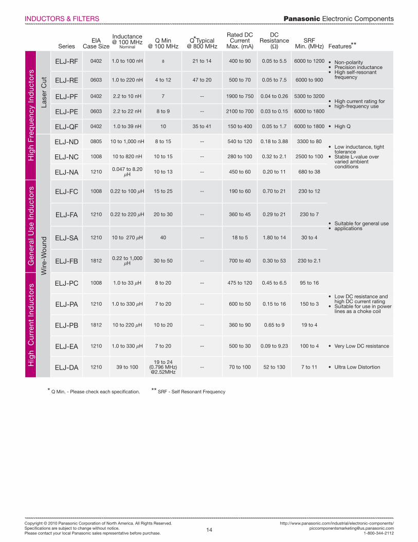
SeriesEIA
Case Size
Inductance@ 100 MHz
NominalQ Min
@ 100 MHzQ Typical
@ 800 MHz
Rated DC Current
Max. (mA)
DCResistance
(O)SRF
Min. (MHz) Features
Hig
h F
req
uenc
y In
duc
tors
Lase
r C
ut
ELJ-RF 0402 1.0 to 100 nH 8 21 to 14 400 to 90 0.05 to 5.5 6000 to 1200 • Non-polarity• Precision inductance• High self-resonant
frequencyELJ-RE 0603 1.0 to 220 nH 4 to 12 47 to 20 500 to 70 0.05 to 7.5 6000 to 900
ELJ-PF 0402 2.2 to 10 nH 7 -- 1900 to 750 0.04 to 0.26 5300 to 3200• High current rating for • high-frequency use
ELJ-PE 0603 2.2 to 22 nH 8 to 9 -- 2100 to 700 0.03 to 0.15 6000 to 1800
ELJ-QF 0402 1.0 to 39 nH 10 35 to 41 150 to 400 0.05 to 1.7 6000 to 1800 • High Q
Wire
-Wo
und
ELJ-ND 0805 10 to 1,000 nH 8 to 15 -- 540 to 120 0.18 to 3.88 3300 to 80• Low inductance, tight
tolerance• Stable L-value over
varied ambient conditions
ELJ-NC 1008 10 to 820 nH 10 to 15 -- 280 to 100 0.32 to 2.1 2500 to 100
ELJ-NA 1210 0.047 to 8.20 uH 10 to 13 -- 450 to 60 0.20 to 11 680 to 38
Gen
eral
Use
Ind
ucto
rs ELJ-FC 1008 0.22 to 100 uH 15 to 25 -- 190 to 60 0.70 to 21 230 to 12
• Suitable for general use• applications
ELJ-FA 1210 0.22 to 220 uH 20 to 30 -- 360 to 45 0.29 to 21 230 to 7
ELJ-SA 1210 10 to 270 uH 40 -- 18 to 5 1.80 to 14 30 to 4
ELJ-FB 1812 0.22 to 1,000 uH 30 to 50 -- 700 to 40 0.30 to 53 230 to 2.1
Hig
h C
urre
nt I
nduc
tors
ELJ-PC 1008 1.0 to 33 uH 8 to 20 -- 475 to 120 0.45 to 6.5 95 to 16
• Low DC resistance and high DC current rating
• Suitable for use in power lines as a choke coil
ELJ-PA 1210 1.0 to 330 uH 7 to 20 -- 600 to 50 0.15 to 16 150 to 3
ELJ-PB 1812 10 to 220 uH 10 to 20 -- 360 to 90 0.65 to 9 19 to 4
ELJ-EA 1210 1.0 to 330 uH 7 to 20 -- 500 to 30 0.09 to 9.23 100 to 4 • Very Low DC resistance
ELJ-DA 1210 39 to 10019 to 24
(0.796 MHz) @2.52MHz
-- 70 to 100 52 to 130 7 to 11 • Ultra Low Distortion
***
* Q Min. - Please check each specification. ** SRF - Self Resonant Frequency
INDUCTORS & FILTERS

Panasonic Electronic Components
15Copyright © 2010 Panasonic Corporation of North America. All Rights Reserved.Specifi cations are subject to change without notice.Please contact your local Panasonic sales representative before purchase.
Panasonic Electronic Componentshttp://www.panasonic.com/industrial/electronic-components/
1-800-344-2112
Type SeriesCase Size
Impendance(O) Tolerance
Cap.(pF)
Rated DC Current
DCResistance
Max (O) Features
Sur
face
Mou
nt F
ilter
s
Com
mon
Mod
e N
oise
Filt
er EXC-14CE 0302Common mode
Z: 65, 90+-20% 130 mA 2.5
• Low DC Resistance And Insertion Loss
• Low Profi le
EXC-24CG 0504Common mode
Z:24, 90+-20%
160mA, 100mA
1.5, 3.0• Meet The Mask-Test For HDMI• High Reliability
EXC-24CE EXC-24CF
0504Common mode
Z:36 ~ 200+-25%
130mA ~ 200 mA
1.0 ~ 2.70• High-Q Impedance Available• Magnetic Shield
EXC-28CE 0804Common mode
Z:90 ~ 200+-25%
130mA ~ 160 mA
1.5 ~ 2.50 • 2 Common Mode Noise Filters Per Package
• Magnetic Shield• Small SizeEXC-28CG 0804
Common mode Z:90
+-25% 130 mA 3.0
2 M
ode
Noi
se F
ilter
EXC-24CB/CP EXC-24CN
0504Common mode Z:120 ~ 1000
+-25%50mA ~ 500 mA
0.3 ~ 1.5
• Burst/Radiation Noise Reduction For Audio Circuits
• Filtering Common & Normal Mode Noises
• Magnetic Shielding
Chi
p
Bea
d
Cor
es EXC-CL EXC-ML EXC-3B
0603 ~
4532
Z: 25 ~ 115Z: 27 ~ 68
Z: 60 ~ 1000+-25%
50mA ~ 2000 mA
0.1 ~ 1.0• Effective Noise Suppression For
Power Lines And High Speed Signal Lines
Chi
p
Bea
d
Arr
ay EXC-28BA EXC-28BB
0804 Z: 120, 220 +-25% 100 mA 0.5, 0.7• SSOP Package (0.5mm Pitch)
Compatibility• Small Size
Chi
p
EXC-CET 1807 +-20% 22 ~ 10K 2A 0.05• Wide Capacitance Range• Suitable For Narrow Pitch Insertion
Coi
l
ELK-E 1207 10 ~ 33K• For Filtering Digital Noise • Stable Attenuation Characteristics
Over Current Changes
Lead
ed F
ilter
s
Lead
edB
ead
Cor
e
EXC-EL 30 ~ 160 7A 0.01• For High Frequency Applications • Radial And Axial Types Available• Lower Cost
INDUCTORS & FILTERS

Panasonic Electronic Components
16Copyright © 2010 Panasonic Corporation of North America. All Rights Reserved.Specifi cations are subject to change without notice.Please contact your local Panasonic sales representative before purchase.
http://www.panasonic.com/industrial/electronic-components/[email protected]
1-800-344-2112
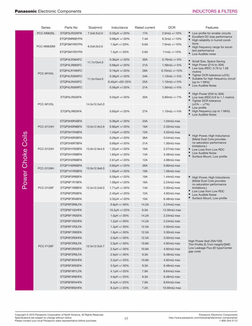
INDUCTORS & FILTERS
Series Size (mm) Inductance RangeSaturation
Rated Current FeaturesC
hip
Cho
ke C
oils
ELL-3FU 3.0 x 3.0 x 1.2 1.0 ~ 10.0 µH 600 ~ 1700 mA• Large Current, Low Loss• Magnetic Shielding• Low Profile
ELL-VEGELL-VFGELL-VGG
3.0 x 3.0 x 1.03.0 x 3.0 x 1.23.0 x 3.0 x 1.5
1.0 ~ 68.0 µH 350 ~ 2200 mA
• Magnetic Shielding• Low DC Resistance & large
current capability• Vibration Resistant
ELC-VENELC-VFN
3.0 x 3.0 x 1.03.0 x 3.0 x 1.2
1.0 ~ 22.0 µH 330 ~ 1750 mA• Low DC Resistance & large
current capability• Vibration ResistantELC-3FN
ELC-3GN3.2 x 3.2 x 1.23.2 x 3.2 x 1.5
1.0 ~ 68.0 µH 190 ~ 1400 mA
ELL-PFG 3.6 x 3.6 x 1.2 1.0 ~ 68.0 µH 240 ~ 1700 mA
• Magnetic Shielding• Low DC Resistance & large
current capability• Vibration Resistant
ELL-4FGELL-4GGELL-4LG
3.8 x 3.8 x 1.23.8 x 3.8 x 1.43.8 x 3.8 x 1.8
1.0 ~ 150.0 µH 220 ~ 2400 mA
ELL-SFG 4.0 x 4.0 x 1.2 1.2 ~ 470.0 µH 100 ~ 1800 mA
ELC-5FN 4.5 x 4.5 x 1.2 2.4 ~ 47.0 µH 320 ~ 1300 mA• Low DC Resistance & large
current capability• Vibration Resistant
ELL-5PS 5.0 x 5.0 x 2.0 1.2 ~ 100.0 µH 300 ~ 2500 mA• Magnetic Shielding• Low DC Resistance & large
current capability
ELL-6RHELL-6SHELL-6UH
6.0 x 6.0 x 2.86.0 x 6.0 x 3.36.0 x 6.0 x 5.0
1.0 ~ 1000.0 µH 180 ~ 3400 mA• Thin• High Mounting Reliability• Large Current Capability
ELL-6GGELL-6GP
6.0 x 6.0 x 1.66.0 x 6.0 x 2.0
0.8 ~ 100.0 µH 380 ~ 2500 mA• Magnetic Shielding• Low DC Resistance & large
current capability
ELC-6GN 6.0 x 6.0 x 1.6 1.2 ~ 68.0 µH 450 ~ 2700 mA• Low DC Resistance & large
current capability
ELL-ATV 10.0 x 10.0 x 4.5 1.5 ~ 1000.0 µH 320 ~ 6700 mA • Magnetic Shielding• Low DC Resistance & large
current capability• Available on Tape & Reel for
automatic insertionELL-CTV 12.0 x 12.0 x 4.5 1.2 ~ 1000.0 µH 410 ~ 6500 mA
Series Parts No Size(mm) Inductance Rated current DCR Features
Po
wer
Cho
ke
Co
ils
PCC-M0754METQP5M4R7YFM
7.5x7.0x5.44.7uH +/-20% 4.5A 20.4mohm +/-10%
• High Heat Resistance• High Reliability• High Bias Current• Temperature Stability• Low Audible Noise• Highly Efficient
ETQP5M470YFM 48uH +/-20% 1.6A 156mohm +/-10%
PCC-M0854M
ETQP5M2R5YFK
8.5x8.0x5.4
2.45uH +/-20% 7.5A 7.6mohm +/-10%
ETQP5M220YFK 22uH +/-20% 2.6A 63mohm +/-10%
ETQP5M470YFK 48uH +/-20% 1.8A 125mohm +/-10%
PCC-M1054M
ETQP5M2R5YFC
10.7x10x5.4
2.5uH +/-20% 10A 5.3mohm +/-10%
ETQP5M3R3YFC 3.3uH +/-20% 8.6A 7.1mohm +/-10%
ETQP5M4R7YFC 4.7uH +/-20% 7.2A 10.2mohm +/-10%
PCC-M105YGC ETQP5M101YGC 10.7x10x5.0 97uH +/-20% 1.6A 208mohm +/-10%
Panasonic Electronic Components
17Copyright © 2010 Panasonic Corporation of North America. All Rights Reserved.Specifi cations are subject to change without notice.Please contact your local Panasonic sales representative before purchase.
Panasonic Electronic Componentshttp://www.panasonic.com/industrial/electronic-components/
1-800-344-2112
INDUCTORS & FILTERS
Series Parts No Size(mm) Inductance Rated current DCR FeaturesP
ower
Cho
ke C
oils
PCC-M0630L ETQP3LR33XFN 7.5x6.5x3.0 0.33µH +/-20% 17A 2.0mO +/-10% • Low profile for smaller circuits• Excellent DC bias performance• High reliability in humid condi-
tions• High frequency range for excel-
lent performance• Low Audible noise
PCC-M0630M
ETQP3MR68YFN
6.5x6.0x3.0
0.68µH +/-20% 7.4A 6.3mO +/-10%
ETQP3M1R0YFN 1.0µH +/-20% 6.6A 7.9mO +/-10%
ETQP3M1R5YFN 1.5µH +/-20% 5.6A 11mO +/-10%
PCC-M104L
ETQP4LR36AFC11.7x10x4.0
0.36µH +/-20% 30A 0.76mO +/-5% • Small Size, Space Saving• High Power (21A to 30A)• Low loss (RDC: 0.76 to 1.58
mohm)• Tighter DCR tolerance (±5%)• Suitable for high frequency circuit
(up to 1 MHz)• Low Audible Noise
ETQP4LR68XFC 0.68µH +/-20% 21A 1.58mO +/-5%
ETQP4LR19WFC
11.5x10x4.0
0.19µH +/-20% 28A 0.70mO +/-10%
ETQP4LR36WFC 0.36µH +/-20% 24A 1.10mO +/-5%
ETQP4LR45XFC 0.45µH +20/-25% 25A 1.10mO +/-5%
ETQP4LR56WFC 0.56µH +/-20% 21A 1.56mO +/-5%
PCC-M125L
ETQP5LR50XFA
14.5x12.5x5.0
0.50µH +/-20% 30A 0.80mO +/-7%• High Power (25A to 30A)• Low loss (RDC:0.8 to 1.1 mohm)• Tighter DCR tolerance
(±5% ~ ±7%)• Low profile• High frequency (up to 1 MHz)• Low Audible Noise
ETQP5LR60XFA 0.60µH +/-20% 27A 1.10mO +/-5%
PCC-D124H
ETQP3H0R4BFA
13.0x12.9x3.9
0.36µH +/-20% 23A 1.04mO max
• High Power, High Inductance(Metal Dust Core provides no saturation performance limitations.)
• Low Loss from Low RDC• Low Audible Noise• Surface Mount, Low profile
ETQP3H0R8BFA 0.80µH +/-20% 16A 2.33mO max
ETQP3H1R4BFA 1.43µH +/-20% 12A 4.52mO max
PCC-D125H
ETQP2H0R3BFA
13.0x12.9x4.9
0.29µH +/-20% 36A 0.54mO max
ETQP2H0R7BFA 0.69µH +/-20% 21A 1.30mO max
ETQP2H1R2BFA 1.22µH +/-20% 16A 2.27mO max
ETQP2H1R8BFA 1.83µH +/-20% 14A 3.48mO max
ETQP2H2R6BFA 2.61µH +/-20% 12A 4.98mO max
PCC-D126HETQP1H0R6BFA
13.0x12.9x6.00.60µH +/-25% 26A 0.90mO max
ETQP1H1R0BFA 1.00µH +/-20% 19A 1.56mO max
PCC-D126F
ETQP6F0R6BFA
12.5x12.5x6.0
0.58µH +/-20% 19A 1.44mO max • High Power, High Inductance(Metal Dust Core provides no saturation performance limitations.)
• Low Loss from Low RDC• Low Audible Noise• Surface Mount, Low profile
ETQP6F1R1BFA 1.06µH +/-20% 16A 2.24mO max
ETQP6F1R8BFA 1.71µH +/-20% 14A 3.30mO max
ETQP6F2R5BFA 2.45µH +/-20% 12A 4.92mO max
ETQP6F3R4BFA 3.32µH +/-20% 10A 6.48mO max
PCC-F126F
ETQP6F0R8LFA
12.5x12.5x5.7
0.8µH +/-30% 14.2A 2.24mO max
High Power (Isat 20A/100)Thin Profile (5.7mm height)/SMDLow Leakage Flux (EI type/Center gap core)
ETQP6F102HFA 10.2µH +/-25% 6.5A 13.30mO max
ETQP6F1R0SFA 1.0µH +/-30% 14.2A 2.24mO max
ETQP6F1R2HFA 1.2µH +/-30% 14.2A 2.24mO max
ETQP6F1R3LFA 1.3µH +/-30% 12.5A 3.30mO max
ETQP6F1R6SFA 1.6µH +/-30% 12.5A 3.30mO max
ETQP6F2R0HFA 2.0µH +/-30% 12.5A 3.30mO max
ETQP6F2R0LFA 2.0µH +/-30% 10.8A 4.92mO max
ETQP6F2R5SFA 2.5µH +/-30% 10.8A 4.92mO max
ETQP6F2R9LFA 2.9µH +/-30% 9.3A 6.48mO max
ETQP6F3R2HFA 3.2µH +/-25% 10.8A 4.92mO max
ETQP6F3R5SFA 3.5µH +/-30% 9.3A 6.48mO max
ETQP6F4R1LFA 4.1µH +/-20% 7.9A 8.64mO max
ETQP6F4R6HFA 4.6µH +/-25% 9.3A 6.48mO max
ETQP6F6R4HFA 6.4µH +/-25% 7.9A 8.64mO max
ETQP6F8R2HFA 8.2µH +/-25% 7.2A 10.90mO max

Panasonic Electronic Components
18Copyright © 2010 Panasonic Corporation of North America. All Rights Reserved.Specifi cations are subject to change without notice.Please contact your local Panasonic sales representative before purchase.
http://www.panasonic.com/industrial/electronic-components/[email protected]
1-800-344-2112
Type Part Number Case Size Varistor VoltageMax. Allowable
Voltage (DC) CapacitanceMaximum ESD[IE061000-4-2]
Vari
sto
rs
Low
Cap
acit
ance
EZJ-ZZV120EA0201
12 V 6.7 V 47 pF max
Contact Discharge Voltage: 8kV
Air Gap DischargeVoltage: 15kV
EZJ-ZZV270RA 27 V 16 V 20 pF max
EZJ-Z0V080KA
0402
8 V 5 V 330 pF max
EZJ-Z0V120JA 12 V 6.7 V 220 pF max
EZJ-Z0V270RA27 V 16 V
47 pF max
EZJ-Z0V270EA 20 pF max
EZJ-Z1V080KA
0603
8V 5 V330 pF max
EZJ-Z1V120KA 12 V 6.7 V
EZJ-Z1V270GA 27 V 16 V100 pF max
EZJ-Z1V330GA 33 V 26 V
Ult
ra L
ow
Cap
acit
ance
EZJ-ZZV800AA 0201
80 V
5 V 3 pF max
EZJ-Z0V80010
0402
18 V 1 pF max
EZJ-Z0V80015D5 V
1.5 +_0.5 pF
EZJ-Z0V500AA 50 V
EZJ-Z0V800AA 80 V
18 VEZJ-Z0V171AA 170 V
EZJ-Z1V80010
0603
80 V
EZJ-Z1V500AA 50 V 5 V
EZJ-Z1V800AA 80 V18 V
EZJ-Z1V171AA 170 V
Vari
sto
r A
rray
s
2 A
rray
EZJ-ZSV120JA
0504
12 V 6.7 V 220 pF max
EZJ-ZSV270RA27 V 16 V
20 pF max
EZJ-ZSV270EA 47 pF max
EZJ-ZSV800AA 80 V18 V 3 pF max
EZJ-ZSV171AA 170 V
4 A
rray
EZJ-P0V080MA
0402 8 V 5.6 V
680 pF max
EZJ-P0V080KA 330 pF max
EZJ-P0V080GA 100 pF max
EZJ-P0V080DA 27 pF max
2 Va
risto
rs2
Cap
acito
rsP
er A
rray
EZJ-ZSV270DA
0504 27 V 16 V
27 pF
EZJ-ZSV270PA 33 pF
EZJ-ZSV270SA 39 pF
EZJ-ZSV270TA 43 pF
EZJ-ZSV270EA 47 pF
Vari
sto
rs
Hig
h C
apac
itanc
e EZJ-S1VB822
0603
12 V 6 V 8200 pF
Contact DischargeVoltage: 30kV
EZJ-S1VC392 30 V 18 V 3900 pF
EZJ-S1VD182 50 V 30 V 1800 pF
EZJ-S2VB223
0805
12 V 6 V 22000 pF
EZJ-S2YC822 30 V 18 V 8200 pF
EZJ-S2YD472 50 V 30 V 4700 pF
CIRCUIT PROTECTION

Panasonic Electronic Components
19Copyright © 2010 Panasonic Corporation of North America. All Rights Reserved.Specifi cations are subject to change without notice.Please contact your local Panasonic sales representative before purchase.
Panasonic Electronic Componentshttp://www.panasonic.com/industrial/electronic-components/
1-800-344-2112
Series AppearanceCase Size (EIA)
LxWxH (mm) Electrical CharacteristicsOperating
Temperature Features
Mul
ti-la
yer
Var
isto
r
Zin
c-o
xid
e
Su
rfa
ce
Mo
un
tEZJ-ZZ 0201
(0.6 x 0.3 x 0.3)
Varistor Voltages: 12 ~ 80 VDCCapacitance: 1 ~ 47 pF Max
8 kV Max. ESD Capability
-40 to 85°C
• Very small case size
EZJ-Z0 0402(1.0 x 0.5 x 0.5)
Varistor Voltages: 12 ~ 170 VDCCapacitance: 1 ~220 pF Max.
8 kV Max. ESD Capability • Small case sizes• Low capacitance loading• Ideal for high speed signal lines
EZJ-Z1 0603(1.6 x 0.8 x 0.8)
Varistor Voltages: 12 ~ 170 VDCCapacitance: 1 ~ 330 pF Max.
8 kV Max. ESD Capability
EZJ-ZSArray
0504(1.37 x 1.0 x 0.6)
Varistor Voltages: 12 ~ 170 VDCCapacitance: 3 ~ 220 pF Max.
8 kV Max. ESD Capability
-40 to 85°C
• 2 Varistors per array• Part count reduction• Board space savings
EZJ-P0
Array
0402(1.0 x 0.5 x 0.5)
Varistor Voltages: 8 VDCCapacitance: 27 ~ 680 pF Max.
8 kV Max. ESD Capability
• 4 Varistors per array• Part count reduction• Board space savings• Excellent ESD Suppression
Str
on
tiu
mT
ita
na
te
EZJ-S1 0603(1.37 x 1.0 x 0.6)
Varistor Voltages: 12 ~ 50 VDCCapacitance: 1,800 ~ 8,200 pF Max.
30 kV Max. ESD Capability
-40 to 85°C • High ESD capabilities
EZJ-S2 0805(2.0 x 1.25 x .85)
Varistor Voltages: 12 ~ 50 VDCCapacitance: 4,700 ~ 22,000 pF Typical
30 kV Max. ESD Capability
ZN
RS
urg
e A
bso
rber
s
Zin
c-o
xid
e ERZ-VF Molded Case(6.0 x 8.0 x 3.2)
Varistor Voltages: 22 ~ 470 VDCMax. Peak Currents: 125 to 300 A -40 to 85°C
• Flow (wave) / Refl ow soldering• UL (Pending)
Le
ad
ed
ERZ-VD 5 to 20 mmDiameter Disc
Varistor Voltages: 18 to 1,800 VDCMax. Peak Currents: 125 to 6,500 A
-40 to 85°C
• Large energy handling capabilities
• UL / VDE / CSA Safety Certifi cations
• QS9000
Series AppearanceCase Size (EIA)
LxWxH (mm) Electrical CharacteristicsOperating
Temperature Features
Mul
ti-l
ayer
NT
C T
herm
isto
rs
ERT-JZ 0201(0.6 x 0.3 x 0.3)
Nominal Resistance @ 2K ~ 1000K O
-40 to 125°C
• Surface Mount 0201, 0402, 0603• Highly Reliable• Multi-layer & Monolithic
available• Lead Free (RoHS)
ERT-J0 0402(1.0 x 0.5 x 0.5)
Nominal Resistance @22 ~ 470K O
Power Dissipation33 mW ~ 100mW
ERT-J1 0603(1.6 x 0.8 x 0.8)
Nominal Resistance @22 ~ 150K O
1 mW/°C ~ 3m W/°C
CIRCUIT PROTECTION
Thickness 0.10 ±0.03 mm 0.07 ±0.015 mm 0.025 ±0.010 mm
Density 0.85 g/cm³ 1.1 g/cm³ 2.1 g/cm³
Thermal Conductivity a-b plane 600 to 800 W/(m-K) 750 to 950 W/(m-K) 1500 to 1700 W/(m-K)
Electrical Conductivity 10,000 S/cm 10,000 S/cm 20,000 S/cm
Extensional Strenght 19.6 MPa 22.0 MPa 30.0 MPa
Expansion Coefficient a-b plane 9.3 X 10⁻⁷ 1/K 9.3 X 10⁻⁷ 1/K 9.3 X 10⁻⁷ 1/K
c axis 3.2 X 10⁻⁵ 1/K 3.2 X 10⁻⁵ 1/K 3.2 X 10⁻⁵ 1/K
Heat Resistance 400°C
Bending (180° angle, R5) 10,000 Cycles
Part Number Dimension X (mm) Dimension Y (mm) Thickness (mm)
EYGS1823(10, 07) 180 ±5 230 ±5 0.10 ±0.03, 0.07 ±0.015
EYGS1218(10, 07, 03) 115 ±5 180 ±5 0.10 ±0.03, 0.07 ±0.015, 0.025 ±0.010
EYGS0912(10, 07, 03) 90 ±5 115 ±5 0.10 ±0.03, 0.07 ±0.015, 0.025 ±0.010
Pyr
oly
tic
Gra
phi
te S
heet
(P
GS
)

Panasonic Electronic Components
20Copyright © 2010 Panasonic Corporation of North America. All Rights Reserved.Specifi cations are subject to change without notice.Please contact your local Panasonic sales representative before purchase.
http://www.panasonic.com/industrial/electronic-components/[email protected]
1-800-344-2112
Type Series Appearance L x W x H (mm) Operating Force FeaturesLi
ght
To
uch
Sw
itch
es
Top Push EVP-AF 3.0 x 2.6 x 0.65 1.6 N (160 gf)• Built-in actuator for consistent tactile performance• World’s smallest with actuator
Top Push EVP-AA 3.5 x 2.9 x 1.43.5 x 2.9 x 1.7
1.0 N (100 gf)1.6 N (160 gf)2.4 N (240 gf)3.5 N (350 gf)5.0 N (500 gf)
• Super small-sized, thin profile• J-bent terminal• Wide range of operating force• Long operating life
Top Push EVQ-P64.1 x 4.1 x 0.384.1 x 4.1 x 0.434.1 x 4.1 x 0.58
1.0 N (100 gf)1.6 N (160 gf)2.4 N (240 gf)3.5 N (350 gf)
• Compact/Thin Profile• Long-life: up to 1,000,000 cycles min.• Optional push-plate for improved actuation• Optional ground terminal for ESD protection
Top Push EVQ-PQ 4.5 x 4.5 x 0.551.6 N (160 gf)2.4 N (240 gf)
• Thin Profile• Sealing film for dust resistance
Top PushEVQ-P2EVQ-3P2
4.7 x 3.5 x 2.54.7 x 3.5 x 2.1
1.0 N (100 gf)1.6 N (160 gf)2.4 N (240 gf)2.5 N (250 gf)3.5 N (350 gf)5.0 N (500 gf)
• J-bent terminals• Ground terminal optional• Middle Push: 0.7 mm• Short Push: 0.25 mm
Top Push EVQ-PL 4.9 x 4.9 x 0.84.9 x 4.9 x 1.5
1.0 N (100 gf)1.6 N (160 gf)2.6 N (260 gf)
• Optional push-plate for improved actuation• GND terminal included
Top PushEVQ-P0EVQ-Q2
6.5 x 6.0 x 2.06.5 x 6.0 x 2.56.5 x 6.0 x 3.1
0.5 N (50 gf)1.3 N (130 gf)1.6 N (160 gf)2.6 N (260 gf)3.5 N (350 gf)5.0 N (500 gf)
• Low cost• Wide selection of height and force• Wide push plate for reliable actuation• Over-stroke & GND type available• Long operating life
Double ActionEVQ-3PEVQ-PR
6.0 x 6.0 x 0.96.0 x 6.0 x 1.05
1st 0.7 N,2nd 2.6 N1st 1.0 N, 2nd 2.6 N
• Double action for Camera shutter function• Push plate, Boss & Ground as options
Side Operated EVQ-P7 3.5 x 2.9 x 1.351.6 N (160 gf)2.2 N (220 gf)
• High impact resistance• Boss and L-terminal available
Double Action,Side Operated EVQ-Q0 6.2 x 3.5 x 5.25 1.0 N / 2.6 N • Double action for camera shutter function
• Edge mount for ultra hight impact resistance
Side Operated EVQ-PU 4.7 x 3.5 x 1.651.6 N (160 gf)2.2 N (220 gf)
• High impact resistance• Straight or J-bent terminals
Side OperatedEVQ-P4EVQ-P8
6.2 x 3.5 x 3.06.2 x 3.5 x 3.4
1.0 N (100 gf)1.6 N (160 gf)2.4 N (240 gf)2.5 N (250 gf)3.5 N (350 gf)5.0 N (500 gf)
• Optional edge mount for ultra high impact resistance• 0.25 mm, 0.70 mm travel• Life: 200 K to 1 Million cycles
Side Operated EVQ-PS 6.1 x 4.0 x 1.81.6 N (160 gf)2.2 N (220 gf)
• Straight or J-bent terminals• With or without positioning boss
Long TravelEVQ-P1EVQ-9P
6.1 x 6.0 x 5.0
2.0 N (200 gf)2.2 N (220 gf)2.5 N (250 gf)3.5 N (350 gf)
• Push travel: 1.0 mm, 1.3 mm• Popular for automotive applications• J-bent terminal• Large push plate for superior actuation
Long Travel EVQ-Q1 8.5 x 8.5 x 6.54.0 N (400 gf)5.0 N (500 gf)
• Ultra high force• Popular for automotive applications• Large push plate for superior actuation• J-Bent Terminal
Center Space,Long Travel EVP-AD 9.8 x 10.15 x 4.6 4.0 N (400 gf)
• World’s fi rst open Center Space for LED• Long travel of 1.0mm• 100K life
Multi-Function5 Way EVQ-WH 6.0 x 3.5 x 4.36
1.0 N (100 gf)1.6 N (160 gf)2.4 N (240 gf)
• Compact and thin profile• Optional boss for stability
Multi-Function5 Way EVQ-Q7 7.7 x 7.7 x 1.75
Push: 2.6 NLeaning: 1.3 N
• Compact and thin profile• Long life• Dust-proof structure
ELECTROMECHANICAL
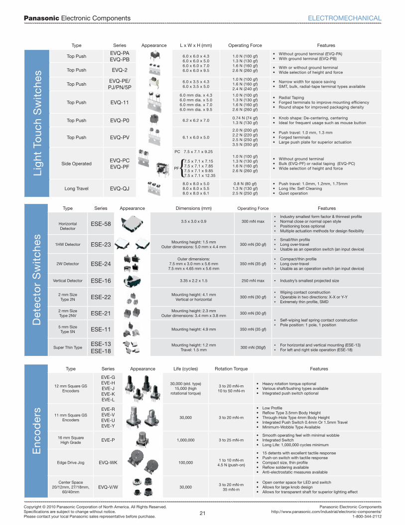
Panasonic Electronic Components
21Copyright © 2010 Panasonic Corporation of North America. All Rights Reserved.Specifi cations are subject to change without notice.Please contact your local Panasonic sales representative before purchase.
Panasonic Electronic Componentshttp://www.panasonic.com/industrial/electronic-components/
1-800-344-2112
Type Series Appearance L x W x H (mm) Operating Force FeaturesLi
ght
To
uch
Sw
itche
s
Top PushEVQ-PAEVQ-PB
6.0 x 6.0 x 4.36.0 x 6.0 x 5.06.0 x 6.0 x 7.06.0 x 6.0 x 9.5
1.0 N (100 gf)1.3 N (130 gf)1.6 N (160 gf)2.6 N (260 gf)
• Without ground terminal (EVQ-PA)• With ground terminal (EVQ-PB)
Top Push EVQ-2 • With or without ground terminal• Wide selection of height and force
Top PushEVQ-PE/PJ/PN/5P
6.0 x 3.5 x 4.36.0 x 3.5 x 5.0
1.0 N (100 gf)1.6 N (160 gf)2.4 N (240 gf)
• Narrow width for space saving• SMT, bulk, radial-tape terminal types available
Top Push EVQ-116.0 mm dia. x 4.36.0 mm dia. x 5.06.0 mm dia. x 7.06.0 mm dia. x 9.5
1.0 N (100 gf)1.3 N (130 gf)1.6 N (160 gf)2.6 N (260 gf)
• Radial Taping• Forged terminals to improve mounting efficiency• Round shape for improved packaging density
Top Push EVQ-P0 6.2 x 6.2 x 7.00.74 N (74 gf)1.3 N (130 gf)
• Knob shape: De-centering, centering• Ideal for frequent usage such as mouse button
Top Push EVQ-PV 6.1 x 6.0 x 5.0
2.0 N (200 gf)2.2 N (220 gf)2.5 N (250 gf)3.5 N (350 gf)
• Push travel: 1.0 mm, 1.3 mm• Forged terminals• Large push plate for superior actuation
Side OperatedEVQ-PCEVQ-PF
PC 7.5 x 7.1 x 9.25
7.5 x 7.1 x 7.15 7.5 x 7.1 x 7.85 7.5 x 7.1 x 9.85 7.5 x 7.1 x 12.35
1.0 N (100 gf)1.3 N (130 gf)1.6 N (160 gf)2.6 N (260 gf)
• Without ground terminal• Bulk (EVQ-PF) or radial taping (EVQ-PC)• Wide selection of height and force
Long Travel EVQ-QJ8.0 x 8.0 x 5.08.0 x 8.0 x 5.58.0 x 8.0 x 6.1
0.8 N (80 gf)1.3 N (130 gf)2.5 N (250 gf)
• Push travel: 1.0mm, 1.2mm, 1.75mm• Long life: Self Cleaning• Quiet operation
Det
ecto
r S
wit
ches
Type Series Appearance Dimensions (mm) Operating Force Features
HorizontalDetector
ESE-58 3.5 x 3.0 x 0.9 300 mN max• Industry smallest form factor & thinnest profile• Normal close or normal open style• Positioning boss optional• Multiple actuation methods for design flexibility
1HW Detector ESE-23 Mounting height: 1.5 mmOuter dimensions: 5.0 mm x 4.4 mm
300 mN (30 gf)• Small/thin profile• Long over-travel• Usable as an operation switch (an input device)
2W Detector ESE-24Outer dimensions:
7.5 mm x 3.0 mm x 5.6 mm7.5 mm x 4.65 mm x 5.6 mm
350 mN (35 gf)• Compact/thin profile• Long over-travel• Usable as an operation switch (an input device)
Vertical Detector ESE-16 3.35 x 2.2 x 1.5 250 mN max • Industry’s smallest projected size
2 mm SizeType 2N ESE-22 Mounting height: 4.1 mm
Vertical or horizontal300 mN (30 gf)
• Wiping contact construction• Operable in two directions: X-X or Y-Y• Extremely thin profile, SMD
2 mm SizeType 2NV ESE-21 Mounting height: 2.3 mm
Outer dimensions: 3.4 mm x 3.8 mm300 mN (30 gf)
• Self-wiping leaf spring contact construction• Pole position: 1 pole, 1 position5 mm Size
Type 5N ESE-11 Mounting height: 4.9 mm 350 mN (35 gf)
Super Thin TypeESE-13ESE-18
Mounting height: 1.2 mmTravel: 1.5 mm
300 mN (30gf)• For horizontal and vertical mounting (ESE-13)• For left and right side operation (ESE-18)
{PF
Enc
od
ers
Type Series Appearance Life (cycles) Rotation Torque Features
12 mm Square GS Encoders
EVE-GEVE-HEVE-JEVE-KEVE-L
30,000 (std. type)15,000 (high
rotational torque)
3 to 20 mN-m10 to 50 mN-m
• Heavy rotation torque optional• Various shaft/bushing types available• Integrated push switch optional
11 mm Square GS Encoders
EVE-REVE-VEVE-UEVE-Y
30,000 3 to 20 mN-m
• Low Profi le• Refl ow Type 3.5mm Body Height• Through-Hole Type 4mm Body Height• Integrated Push Switch 0.4mm Or 1.5mm Travel• Minimum-Wobble Type Available
16 mm SquareHigh Grade EVE-P 1,000,000 3 to 25 mN-m
• Smooth operating feel with minimal wobble• Integrated Switch• Long Life: 1,000,000 cycles minimum
Edge Drive Jog EVQ-WK 100,0001 to 10 mN-m
4.5 N (push-on)
• 15 detents with excellent tactile response• Push-on switch with tactile response• Compact size, thin profi le• Refl ow soldering available• Anti-electrostatic measures available
Center Space20/12mm, 27/18mm,
60/40mmEVQ-V/W 30,000
3 to 20 mN-m35 mN-m
• Open center space for LED and switch• Allows for large knob design• Allows for transparent shaft for superior lighting effect
ELECTROMECHANICAL
Panasonic Electronic Components
22Copyright © 2010 Panasonic Corporation of North America. All Rights Reserved.Specifi cations are subject to change without notice.Please contact your local Panasonic sales representative before purchase.
http://www.panasonic.com/industrial/electronic-components/[email protected]
1-800-344-2112
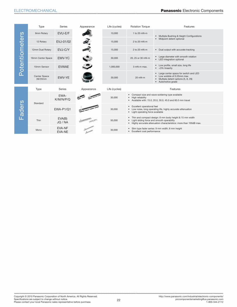
Fad
ers
Type Series Appearance Life (cycles) Features
Standard
EWA-K/M/N/P/Q
30,000• Compact size and wave-soldering type available• High reliability• Available with: 15.0, 20.0, 30.0, 45.0 and 60.0 mm travel
EWA-P1/Q1 30,000• Excellent operational feel• Low noise, long operating life, highly accurate attenuation• Light operating force available
ThinEVA(B)JQ / NA
50,000• Thin and compact design: 8 mm body height & 15 mm width• Light sliding force and smooth operability• Highly accurate attenuation characteristics: more than 100dB max.
MonoEVA-NFEVA-NE
30,000• Slim type fader series: 9 mm width; 8 mm height• Excellent cost performance
Po
tent
iom
eter
sType Series Appearance Life (cycles) Rotation Torque Features
9mm Rotary EVU-E/F 10,000 1 to 20 mN-m• Multiple Bushing & Height Confi gurations• Midpoint detent optional
12 Rotary EVJ-01/02 15,000 2 to 20 mN-m
12mm Dual Rotary EVJ-C/Y 15,000 2 to 20 mN-m • Dual output with accurate tracking
16mm Center Space EWV-YC 30,000 20, 25 or 30 mN-m• Large diameter with smooth rotation• LED integration optional
10mm Sensor EVWAE 1,000,000 3 mN-m max.• Low profi le, small size, long life• <3% linearity
Center Space39/20mm EWV-YE 30,000 20 mN-m
• Large center space for switch and LED• Low wobble of 0.25mm max• Multiple detent options (5, 8, 29)• Automotive grade
ELECTROMECHANICAL

Panasonic Electronic Components
23Copyright © 2010 Panasonic Corporation of North America. All Rights Reserved.Specifi cations are subject to change without notice.Please contact your local Panasonic sales representative before purchase.
Panasonic Electronic Componentshttp://www.panasonic.com/industrial/electronic-components/
1-800-344-2112
Series AppearanceDimensions
(mm)Receiver
SensitivityOperating
Temperature
Max.Output Power
PowerSupply
FrequencyRange I/Os Interfaces
Max. DataRate
(KBits/s)
ISM
PAN2350 20.3 x 14.8 x 4.2-117 dBm
17 mA-40 to +85°C
5 dBm33 mA
2.3 to 3.6 V
402 - 470or
804 - 940 MHz
4 SPI 153.6
PAN2355 8.0 x 8.2 x 1.9 -100 dBm -40 to + 85°C 6 dBm 1.8 to 3.6 V800 - 928
MHz- SPI 500
PAN2365 8.0 x 8.2 x 1.9 -104 dBm -40 to + 85°C 1 dBm 1.8 to 3.6 V 2.4 - SPI 500
PAN2357 8.0 x 8.2 x 1.9 -104 dBm -40 to + 85°C 10 dBm 1.8 to 3.6 V 433 MHz - SPI 500
Blu
eto
oth
®
PAN1315 6.5 x 9.0 x 1.7 -93 dBm -20 to + 70°C 10 dBm 1.7 - 4.8 V 2.4 GHz - SPI, HCI 2100
PAN1315LE
6.5 x 9.0 x 1.7 -93 dBm -20 to + 70°C 10 dBm 1.7 - 4.8 V 2.4 GHz - SPI, HCI TBD
PAN1455 18.7 x 13.4 x 2.2 -86 dBm -40 to + 85°C 4 dBm 2.7 to 3.6 V 2.4 GHz 30GPIO, USB, PCM, UART, SPI, JTAG
2100
PAN1555 22.8 x 20.0 x 4.0 -86 dBm -40 to + 85°C 4 dBm 2.7 to 3.6 V 2.4 GHz 30GPIO, USB, PCM, UART, SPI, JTAG
2100
RP
A
PAN5375 29 x 15 x 4 -97 dBm -40 to + 85°C +20 dBm 2.3 ~ 2.7 V 2.4 GHz - SPI, HCI 2100
802.
15.4
(Mes
h)
PAN4555 16.4 x 12.2 x 2.1 -98 dBm -40 to + 85°C 0 dBm 2.0 to 3.4 V 2.4 GHz 19GPIO, UART,
SPI250
PAN4560 35 x 15 x 3.5 -92 dBm -40 to +85°C 0 dBm 2.7 to 3.3 V 2.4 GHz 33UART, GPIO,
I2C250
PAN4561 35 x 15 x 3.5 -105 dBm -40 to +85°C 20 dBm 2.7 to 3.3 V 2.4 GHz 33UART, GPIO,
I2C, SPI250
PAN4562 35 x 15 x 3.5 -102 dBm -40 to +85°C 10 dBm 2.7 to 3.3 V 2.4 GHz 33UART, GPIO,
I2C, SPI250
PAN4565 35 x 15 x 3.5 -100 dBm -40 to +85°C 0 dBm 2.7 to 3.3 V 2.4 GHz 40UART, SPI, I2C, GPIO
2000
PAN4566 35 x 15 x 3.5 -112 dBm -40 to +85°C 20 dBm 2.7 to 3.3 V 2.4 GHz 40UART, SPI, I2C, GPIO
2000
WIRELESS RF MODULES

Panasonic Electronic Components
24Copyright © 2010 Panasonic Corporation of North America. All Rights Reserved.Specifi cations are subject to change without notice.Please contact your local Panasonic sales representative before purchase.
http://www.panasonic.com/industrial/electronic-components/[email protected]
1-800-344-2112
NOTES
Panasonic Electronic Components
25Copyright © 2010 Panasonic Corporation of North America. All Rights Reserved.Specifi cations are subject to change without notice.Please contact your local Panasonic sales representative before purchase.
Panasonic Electronic Componentshttp://www.panasonic.com/industrial/electronic-components/
1-800-344-2112
NOTES

Panasonic Electronic Components
26Copyright © 2010 Panasonic Corporation of North America. All Rights Reserved.Specifi cations are subject to change without notice.Please contact your local Panasonic sales representative before purchase.
http://www.panasonic.com/industrial/electronic-components/[email protected]
1-800-344-2112
Put The Power of Panasonic’s Website To Work For You Today!
Part Number Search
Parametric Search
Navigational Tools
Clean & User Friendly Interface
Easy to Use Product Support Tools
Quick Access To Contact Panasonic
New Industry Solutions Content
Distributor Product Inventory
The Panasonic Electronic Components web site has become a more functional, usable, and contemporary web site that allows design engineers and distributors to easily & quickly fi nd product content and information, while also allowing them to fi nd a point-of-purchase site or sales person based on easily obtained product information and recommendations.
Visit the web site today for full specifi cations of all the product found in this catalog!
www.panasonic.com/industrial/electronic-components
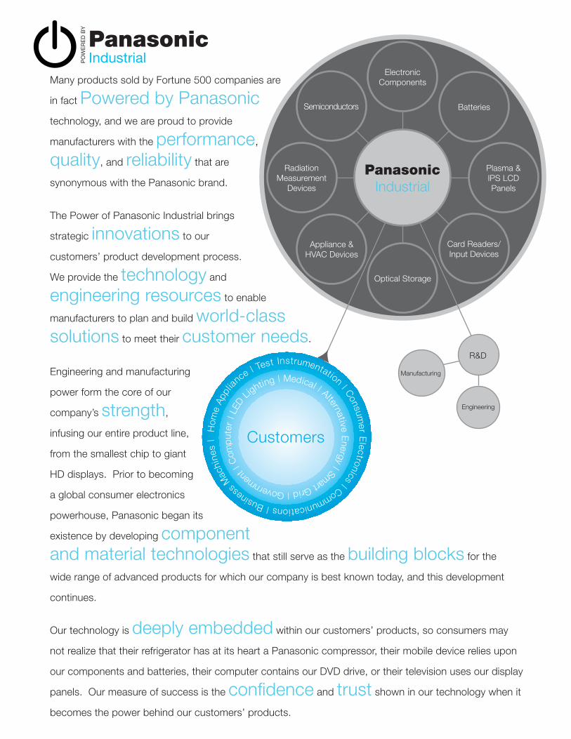
Many products sold by Fortune 500 companies are
in fact Powered by Panasonic
technology, and we are proud to provide
manufacturers with the performance,
quality, and reliability that are
synonymous with the Panasonic brand.
The Power of Panasonic Industrial brings
strategic innovations to our
customers’ product development process.
We provide the technology and
engineering resources to enable
manufacturers to plan and build world-class solutions to meet their customer needs.
Engineering and manufacturing
power form the core of our
company’s strength,
infusing our entire product line,
from the smallest chip to giant
HD displays. Prior to becoming
a global consumer electronics
powerhouse, Panasonic began its
existence by developing component and material technologies that still serve as the building blocks for the
wide range of advanced products for which our company is best known today, and this development
continues.
Our technology is deeply embedded within our customers’ products, so consumers may
not realize that their refrigerator has at its heart a Panasonic compressor, their mobile device relies upon
our components and batteries, their computer contains our DVD drive, or their television uses our display
panels. Our measure of success is the confi dence and trust shown in our technology when it
becomes the power behind our customers’ products.
Electronic Components
Semiconductors Batteries
RadiationMeasurement
Devices
Appliance &HVAC Devices
Optical Storage
Card Readers/Input Devices
Plasma &IPS LCDPanels
Panasonic Industrial
R&D
Engineering
Manufacturing
Hom
e Ap
plian
ce | Test Instrumentation | Consum
er Electronics | Communications | Business
Mac
hine
s |
LED L
ighting | Medical | Alternative Energy | Smart Grid | Governmen
t | C
omp
uter
|
Customers
Industrial

Panasonic Electronic Components
28Copyright © 2010 Panasonic Corporation of North America. All Rights Reserved.Specifi cations are subject to change without notice.Please contact your local Panasonic sales representative before purchase.
http://www.panasonic.com/industrial/electronic-components/[email protected]
1-800-344-2112
PO
WE
RE
D B
Y
PanasonicElectronic Components
www.panasonic.com/industrial/electronic-components1-800-344-2112
Providing cutting edge technology to give your product the performance, reliability and quality that today’s consumers demand.
Panasonic Electronic Components 3 Panasonic Way, Secaucus, NJ 07094
Copyright ©2010 Panasonic Corporation of North America. All Rights Reserved. PIC, CY09-055-7500
Panasonic ideas for life